

Page 1
New
ABUS TECHNOLOGIES INC.
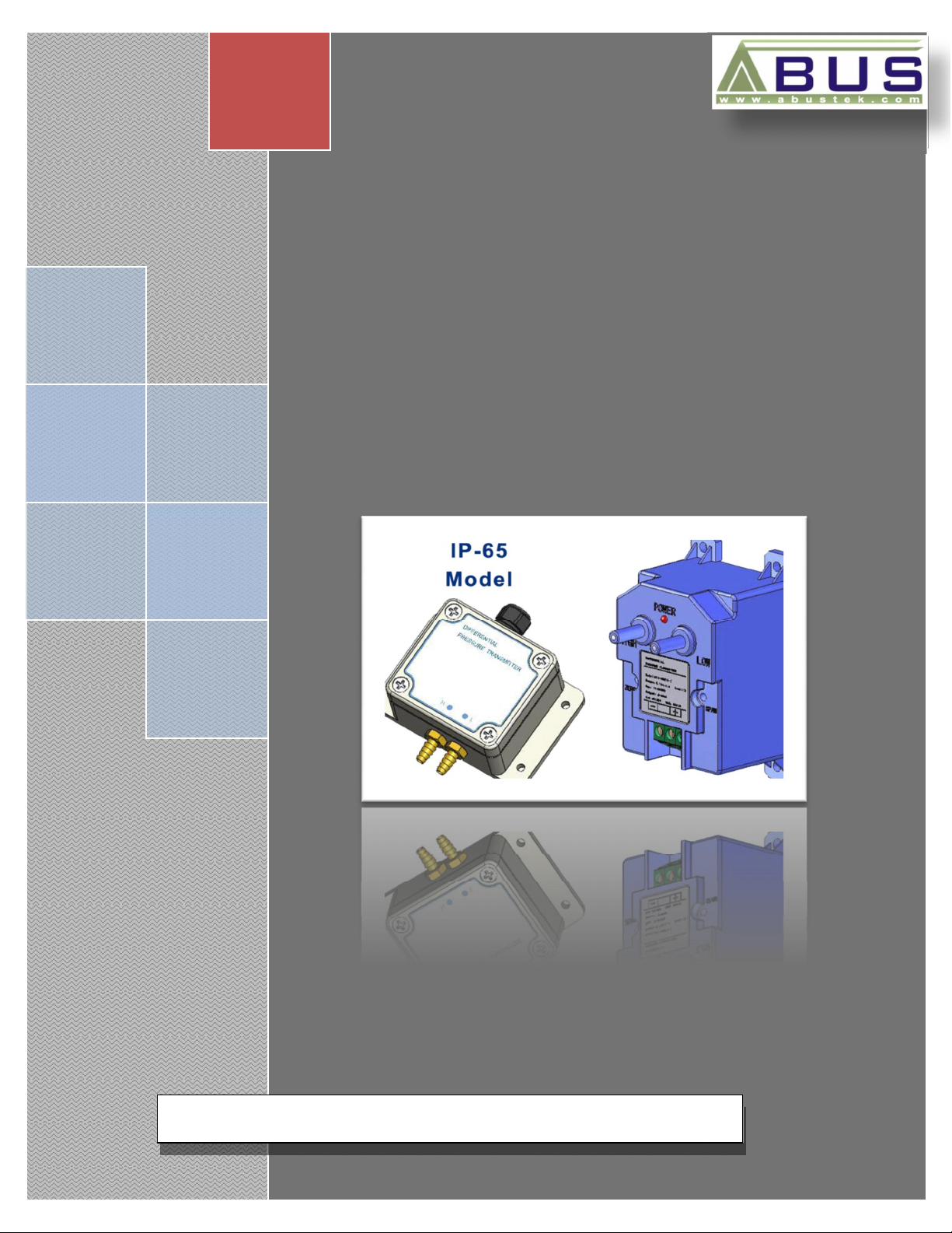
DFT Series-Differential Pressure
Transmitter-Fixed Range
User Manual
Page 2

WARNING
This manual should be passed on to the end user.
The contents of this manual are subject to change without prior notice.
All rights reserved.
ABUS gives no warranty of any kind with regard to this manual, including, but not limited to, fitness for a
particular purpose.
If any question arises or errors are found, or if any information is missing from this manual, please inform
DFT
your supplier or inform at info@abustek.com
.
The specifications mentioned in this manual are limited to those for the standard type under the specified
model number break-down and do not necessarily apply for customized instruments.
Please note that changes in the specifications, construction, or component parts of the instrument may
not immediately be reflected in this manual at the time of change.
If the customer or any third party is harmed by the use of this product, ABUS assumes no responsibility
for any such harm owing to any defects in the product which were not predictable, or for any indirect
damages.
Although Warning hazards are related to personal injury, and Caution hazards are associated with
equipment or property damage, it must be understood that operation of damaged equipment could, under
certain operational conditions, result in degraded process system performance leading to personal injury or
death. Therefore, comply fully with all Warning and Caution notices.
Information in this manual is intended only to assist our customers in the efficient operation of our
equipment. Use of this manual for any other purpose is specifically prohibited and its contents are not to be
reproduced in full or part without prior approval of Technical Communications Department, ABUS
Technologies
HEALTH AND SAFETY
To ensure that our products are safe and without risk to health, the following points must be noted:
1. The relevant sections of these instructions must be read carefully before proceeding.
2. Warning labels on containers and packages must be observed.
3. Installation, operation, maintenance and servicing must only be carried out by suitably trained personnel
and in accordance with the information given. Any deviation from these instructions will transfer the
complete liability to the user.
4. Normal safety precautions must be taken to avoid the possibility of an accident occurring when operating
in conditions of high pressure and/or temperature.
5. Chemicals must be stored away from heat, protected from temperature extremes and powders kept dry.
Normal safe handling procedures must be used.
6. When disposing of chemicals ensure that no two chemicals are mixed.
Safety advice concerning the use of the equipment described in this manual or any relevant hazard data
sheets (where applicable) may be obtained from the Company address on the back cover, together with
servicing and spares information.
ABUS TECHNOLOGIES INC.
2
Page 3

.
DFT
CATALOGUE
Contents Page No.
1. Introduction
Applications
2. Presentation
1. Features
2.
3. Dimensions 5
4. Connections 6
5. Ordering Details 6
6. Installation
1.
2.
7. Maintenance
Calibration
8. Safety Precautions 8
9. Warranty 8
Technical Parameters
Mounting
Pressure Connections
4
4
4
4
4
7
7
7
7
7
ABUS TECHNOLOGIES INC.
3
Page 4

1. INTRODUCTION
The DFT Series, Differential Pressure Transmitter - Fixed Range can accurately
measure negative, positive, combination of both (compound), or differential pressure mainly
applied to air and neutral gases. The DFT Series is not position sensitive and can be
mounted in any orientation without compromising accuracy. The DFT series has a
lightweight, compact and simplified design makes it suitable for industrial applications.
Applications
Cabinet Purging
Air and Neutral Gases
HVAC Applications
Clean Room Applications
Filter Status
Duct Static Pressure
Fan and Blower Pressure
Paint Shops
Dust Collectors
Bubbler Systems
Cabinet Purging
2. PRESENTATION
2.1 Features
1. Lightweight and Simplified Design
2. Compact Design
3. 0.25 % Accuracy
4. LED Power Indication
5. Easy Installation
6. 2-Wire, 4~20 mA output.
DFT
2.2 Technical Parameters
Maximum Pressure : Ranges ≤ 5 PSI – Max 15 PSI
Ranges > 5 PSI – Max 30 PSI
Media compatibility : Air and compatible non combustible, non corrosive gases.
Accuracy : Ranges ≤ 4” w.c. 1.0%
Ranges ≥ 5” w.c. 0.25%
Temperature Ranges : Compensated : 15°F to 120°F (-10°C to 50°C)
Operating : -10°F to 155°F (-25°C to 70°C)
Thermal Effect : ± 0.028% FS/°F
Stability : ± 0.25% FS/year
Output Signal : 4~20 mA, 2-wire
Loop Resistance : 250 Ω @ 24 V dc
Power Supply : 12~30 V dc
Housing Material : ABS Plastic
Electrical Connections : Screw Terminals
Process Connection : Push on connection for ⅛” I.D. Tubing.
ABUS TECHNOLOGIES INC.
4
Page 5

3. DIMENSIONS
DFT
All dimensions in mm
All dimensions in mm
ABUS TECHNOLOGIES INC.
5
Page 6

4. CONNECTIONS
DFT
5. ORDERING DETAILS
TYPE
Product
Size
Power Supply
Analogue Output
Connections
Ranges
DFT Differential Fixed Transmitter
8 48 (W) x 82 (H) x 40 (D) mm
* G = Gauge Pressure
* CP = Compound Pressure
Example: DFT > 8 > A > D > 2 > 1CP
A 24V DC
D
V 0 – 10 V DC
2
4 4-Wire System
1G
2G
3G
4G
5G
6G
7G
8G
1CP
2CP
3CP
4CP
5CP
6CP
NS
4~20mA DC Output
2-Wire System
0-250 Pa 0-1” W.C.
0-500 Pa 0-2” W.C.
0-1 KPa 0-4” W.C.
0-2.5 KPa 0-10” W.C.
0-7 KPa 0-26.7” W.C.
0-35 KPa 0-138.4” W.C.
0-100 KPa 0-415.2” W.C.
0-200 KPa 0-830.4” W.C.
125-0-125 Pa 0.5-0-0.5” W.C.
250-0-250 Pa 1-0-1” W.C.
500-0-500 Pa 2-0-2” W.C.
1.25-0-1.25 KPa 5-0-5” W.C.
50-0-50 KPa 200-0-200” W.C.
100-0-100 KPa 415.2-0-415.2” W.C.
Non Standard (as low as 12.5 Pa)
DESCRIPTION
ABUS TECHNOLOGIES INC.
6
Page 7

6. INSTALLATION
6.1 Mounting
The DFT Series should be mounted in a clean, dry location free from excess
vibration. The transmitter can be mounted in any orientation and should be attached by
using the 4 holes provided on the housing.
6.2 Pressure Connections
Two push on pressure connections are located on the front of the unit, labeled
“High” and “Low”. For best results, connect 1/8” I.D. push on tubing to the pressure
DFT
connections. For differential pressure measurement, the higher pressure should be
connected to the “High” pressure port. For positive pressure, the “Low” pressure port
should be left vented to atmospheric pressure. For negative pressure measurement, the
“High” pressure port should be vented to atmospheric pressure.
7. MAINTENANCE
Calibration
The DFT Series is factory calibrated and should not require calibration out of the
box. Periodically, it may be necessary to recalibrate the gauge to maintain the accuracy of
the product. To “zero” the gauge, remove the pressure connections from both pressure
ports and adjust the zero potentiometer until the output is 4 mA. To “span” the gauge, apply
the full scale pressure to the High pressure port and adjust the span potentiometer until the
output is 20 mA. To properly calibrate the product, it is necessary to have an accurate
pressure standard. If you do not have one available or would like calibration traceable to
NIST, please contact ABUS Technologies Inc.
ABUS TECHNOLOGIES INC.
7
Page 8

8. SAFETY PRECAUTIONS
1. The unit should be powered for 15 minutes before use.
2. Use in ambient temperature of 0-60˚C.
3. Avoid vibrations, shock, excessive dust, corrosive chemical materials or gaseous
environment.
4. Input wire should not be too long. If measured signal have to be far away from the unit,
please use 2-core shielded cable.
5. Use this instrument in the scope of its specifications, otherwise fire or malfunctions
may result.
6. Contact of the instrument, with organic solvents or oils should be avoided.
7. Do not turn on the power supply until all of the wiring is completed. Otherwise electrical
DFT
shock, fire or malfunction may result.
8. Do not disassemble, repair or modify the instrument.
9. All connections should be tightened properly.
10. Power supply should be constant, should not be fluctuating.
9. WARRANTY
ABUS provides the original purchaser of this instrument a one (1) year warranty
against defects in material and workmanship under the following terms:
The one year warranty begins on the day of shipment as stated on the sales bill.
During the warranty period all costs of material and labor will be free of charge
provided that the instrument does not show any evidence of misuse.
For maintenance, return the instrument with a copy of the sales bill to our factory.
All transportation and insurance costs should be covered by the owner of the
equipment.
Should any sign of electrical or mechanical shock, abuse, bad handling or misuse be
evident the warranty voids and maintenance costs will be charged.
ABUS TECHNOLOGIES INC.
www.abustek.com, E-M ail: info@abustek.com
ABUS TECHNOLOGIES INC.
8
 Loading...