

Page 1
Relaisplatine 8-fach
für Terxon SX / MX / LX
Installationsanleitung
Relay board (8x)
Installation Instructions (UK) ..................................................................................4
Carte relais 8 fois
Instructions d’installation (FR)................................................................................6
Relaisprintplaat 8-voudig
Installatie-instructies (NL) ......................................................................................8
Relæprintkort 8-dobbelt
Installationsvejledning (DK) .................................................................................10
Scheda relè 8 x
Istruzioni per l’installazione (I)..............................................................................12
AZ4140
11847215
Page 2

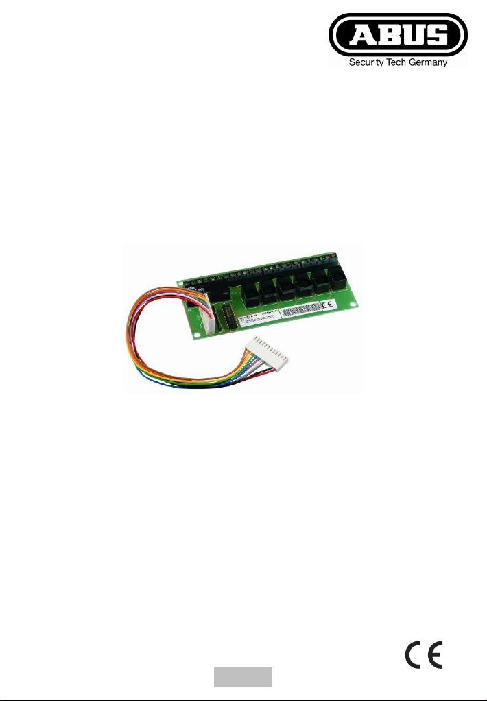
1. Merkmale
Das 8-fach Relaismodul ist eine Erweiterungskomponente für die
Alarmzentralen Terxon SX, Terxon MX und Terxon LX. Durch
Einsatz des Moduls stehen Ihnen zusätzlich 8 Relaisausgänge zur
Verfügung. Die zusätzlichen Transistorausgänge der Zentrale
werden dabei belegt.
Weitere Informationen erhalten Sie in den Installationsanleitungen
der Zentralen.
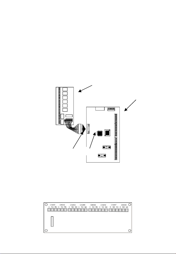
2. Übersicht
Fig. 1
1
2
3 4
1 - 8-fach Relaisplatine
2 - Hauptplatine Terxon SX/MX
3 - Verbindungskabel
4 - Anschluss für zusätzliche Transistorausgänge
Fig. 2:
2
Page 3

3. Installation
1. Setzen Sie die Alarmzentrale in den spannungslosen
Zustand.
2. Für Terxon SX/MX (Verbindungskabel mit 2 Steckern):
Verbinden Sie den 10-poligen Stecker des mitgelieferten
Verbindungskabels mit der Relaisplatine. Verbinden Sie
anschließend das Verbindungskabel (12-poliger Stecker) mit
der Anschlussleiste für die zusätzlichen Transistorausgänge
(weitere Informationen siehe Installationsanleitung Terxon
SX/MX). Stecker und Anschlussleiste rasten durch leichten
Druck ein. Der Stecker passt jeweils nur in einer Position
(Aufdruck auf Stecker und Anschlussleiste prüfen).
Für Terxon LX (Verbindungskabel mit 1 Stecker):
Verbinden Sie den 10-poligen Stecker des mitgelieferten
Verbindungskabels mit der Relaisplatine. Die losen Adern
auf der anderen Seite verdrahten Sie jeweils mit einem der
verfügbaren Transistorausgänge der Zentrale (weitere
Informationen siehe Installationsanleitung Terxon LX).
3. Befestigen Sie die 4 mitgelieferten Plastikfüße an der
Unterseite der Relaisplatine in den 4 Ecklöchern.
4. Schließen Sie nun die Relaisausgänge je nach gewünschter
Schaltungsart NO (normal offen) oder NC (normal
geschlossen) auf der Relaisplatine an (FIG2).
5. Befestigen Sie die Relaisplatine an einer geeigneten Stelle
im Gehäuse der Alarmzentrale mittels des beigefügten
Befestigungsmaterials.
4. Technische Daten
Schaltausgänge
Max. Schaltleistung
8 Relais NC/NO potentialfrei
1 A / 30 V DC
3
Page 4
1. Features
The 8x relay module is an additional component for the Terxon SX,
Terxon MX and Terxon LX alarm centres. When the module is used,
an additional eight relay outputs are available. When connected, the
module occupies the additional transistor outputs of the alarm
centre.
Further information can be found in the installation instructions of
the alarm centre.
2. Overview
Fig. 1
1
2
3 4
1 - 8x relay board
2 - Terxon SX/MX mainboard
3 - Connecting cable
4 - Connection for additional transistor outputs
Fig. 2
4
Page 5

3. Installation
1. Disconnect the alarm centre from the power supply.
2. Terxon SX/MX (connecting cable with two plugs):
Connect the 10-pin plug on the enclosed connecting cable
to the relay board. Connect the connecting cable (12-pin
plug) with the terminal for the additional transistor outputs
(see the Terxon SX/MX installation instructions for more
details). The plug and terminal lock into place when pressed
lightly. The plug only fits in one position (check the imprint
on the plug and terminal).
Terxon LX (connecting cable with one plug):
Connect the 10-pin plug on the enclosed connecting cable
to the relay board. Connect the loose wires on the other side
with one of the available transistor outputs on the alarm
centre (see the Terxon LX installation instructions for more
details).
3. Fasten the four plastic feet (enclosed) to the underside of
the relay board in the four square holes.
4. Connect the relay outputs to the relay board according to
the required switching type (NO (normal open) or NC
(normal closed)) (see FIG2).
5. Fasten the relay board in a suitable position inside the alarm
centre housing using the fixing materials provided.
4. Technical data
Switch outputs
Maximum switching
power
8x relay NC/NO, potential-free
1 A / 30 V DC
5
Page 6

1. Caractéristiques
La carte relais 8 fois est une extension destinée aux centrales
d’alarme Terxon SX, Terxon MX et Terxon LX. Ce module permet
de disposer de 8 sorties relais supplémentaires. Dans ce cadre, les
sorties à transistor supplémentaires de la centrale ne sont plus
libres.
Des informations supplémentaires sont disponibles dans les
instructions d'installation des centrales.
2. Vue d'ensemble
Fig. 1
1
2
3 4
1 – Platine relais 8X
2 – Platine Terxon SX/MX
3 – Câble de raccordement
4 – Connecteur de sorties à transistor supplémentaires
Fig. 2 :
6
Page 7

3. Installation
1. Mettre la centrale d’alarme hors tension.
2. Pour Terxon SX/MX (câble de raccordement à 2
connecteurs):
Brancher le connecteur à 10 broches fourni dans la livraison
à la carte relais. Brancher ensuite le câble de raccordement
(connecteur à 12 broches) à la barrette à bornes destinée
aux sorties à transistor supplémentaires (pour des
informations supplémentaires, consulter les instructions
d’installation de la Terxon SX/MX). Le connecteur et la
barrette à bornes s’enclenchent lors d’une légère pression.
Le connecteur ne peut être enfiché que dans une position
(vérifier la gravure sur le connecteur et sur la barrette à
bornes).
Pour Terxon LX (câble de raccordement à 1 connecteur) :
Brancher le connecteur à 10 broches du câble de
raccordement joint dans la livraison à la carte relais.
Brancher les fils libres de l’autre côté chacun à l'une des
sorties à transistor libres de la centrale (pour plus
d’informations, consulter les instructions d’installation de la
Terxon LX).
3. Fixer les 4 pieds en plastique fournis dans la livraison sur la
face inférieure de la carte relais dans les 4 trous situés dans
les coins.
4. Raccorder maintenant les sorties à relais en fonction du
type de circuit souhaité NO (normalement ouvert) ou NC
(normalement fermé) sur la carte relais (FIG2).
5. Fixer la carte relais à un endroit adéquat dans le boîtier de
la centrale d’alarme, à l’aide du matériel de fixation joint à la
livraison.
4. Fiche technique
Sorties commutables
Puissance de commutation maxi.
8 relais NC/NO exemptes
de potentiel
1 A / 30 V c.c.
7
Page 8

3
1. Kenmerken
De 8-voudige relaismodule is een uitbreidingscomponent voor de
alarmcemtrales Terxon SX, Terxon MX en Terxon LX. Door het
gebruik van de module beschikt u over 8 extra relaisuitgangen. De
extra transistoruitgangen van de centrale worden daarbij
toegewezen.
Meer informatie krijgt u in de installatie-instructies van de centrales.
2. Overzicht
Afb. 1
1
2
4
1 - 8-voudige relaisprintplaat
2 - Hoofdprintplaat Terxon SX/MX
3 - Verbindingskabel
4 - Aansluiting voor extra transistoruitgangen
Afb. 2
8
Page 9

3. Installatie
1. Zet de alarmcentrale in spanningsloze toestand.
2. Voor Terxon SX/MX (verbindingskabel met 2 stekkers):
Verbind de 10-polige stekker van het meegeleverde
verbindingskabel met de relaisprintplaat. Verbind vervolgens
het verbindingskabel (12-polige stekker) met de aansluitstrip
voor de extra transistoruitgangen (meer informatie zie
installatieaanwijzing Terxon SX/MX). Stekker en
aansluitstrip klikken door licht drukken vast. De stekker past
slechts in één positie (opdruk op stekker en aansluitstrip
controleren).
Voor Terxon LX (verbindingskabel met 1 stekker):
Verbind de 10-polige stekker van het meegeleverde
verbindingskabel met de relaisprintplaat. De losse aders
aan de andere kant maakt u met één van de beschikbare
transistoruitgangen van de centrale vast (meer informatie
zie installatieaanwijzing Terxon LX).
3. Bevestig de 4 meegeleverde plastic voetjes aan de
onderkant van de relaisprintplaat in de 4 hoekgaten.
4. Sluit nu de relaisuitgangen volgens de gewenste
schakelwijze NO (normaal open) of NC (normaal gesloten)
aan de relaisprintplaat aan (AFB2).
5. Bevestig de relaisprintplaat op een geschikte plaats in de
behuizing van de alarmcentrale met het bijgevoegde
bevestigingsmateriaal.
4. Technische gegevens
Schakeluitgangen
Max. schakelvermogen
9
8 relais NC/NO potentiaalvrij
1 A / 30 V DC
Page 10

1. Særlige kendetegn
3
Det 8-dobbelte relæmodul til en udvidelseskomponent til
alarmcentralerne Terxon SX, Terxon MX og Terxon LX. Ved at
anvende modulet er der yderligere 8 relæudgange til rådighed.
Centralens ekstra transistorudgange tildeles derved funktioner.
Yderligere oplysninger kan findes i installationsvejledningerne til
centralerne.
2. Oversigt
Fig. 1
1
2
4
1 - 8-dobbelt relæprintkort
2 - Hoverprintkort Terxon SX/MX
3 - Forbindelseskabel
4 - Tilslutning til yderligere transistorudgange
Fig. 2
10
Page 11

3. Installation
1. Sørg for at alarmcentralen ikke har spænding.
2. Til Terxon SX/MX (forbindelseskabel med 2 stik):
Forbind det medleverede forbindelseskabels 10-polede stik
med relæprintkortet. Forbind derefter forbindelseskablet (12polet stik) med tilslutningslisten til de ekstra
transistorudgange (yderligere informationer, se
installationsvejledningen til Terxon SX/MX). Stik og
tilslutningsliste går i hak med et let tryk. Stikket passer kun i
en position (kontrollér mærket på stikket og
tilslutningslisten).
Til Terxon LX (forbindelseskabel med 1 stik):
Forbind det medleverede forbindelseskabels 10-polede stik
med relæprintkortet. De løse ledere på den anden side skal
tilsluttes til centralens ledige transistorudgange (yderligere
informationer, se installationsvejledningen til Terxon LX).
3. Fastgør de 4 medleverede plastikfødder på undersiden af
printkortet i de huller i hjørnerne.
4. Tilslut nu relæudgangene alt efter den ønskede
koblingstype NO (normal åben) eller NC (normal lukket) på
relæprintkortet (FIG2).
5. Fastgør relæprintkortet på et egnet sted i alarmcentralens
hus vha. det vedlagte fastgørelsesmateriale.
4. Tekniske data
Koblingsudgange
Maks. brydeevne
8 relæ NC/NO potentialefri
1 A/30 V DC
11
Page 12

1. Caratteristiche
Il modulo relè 8 x è una componente di ampliamento per le centrali
di allarme Terxon SX, Terxon MX e Terxon LX. L’impiego del
modulo rende disponibli 8 uscite relè supplementari. Le uscite
transistor supplementari della centrale sono in questo modo
occupate.
Ulteriori informazioni sono contenute nelle istruzioni per
l’installazione delle centrali.
2. Panoramica
Fig. 1
1
2
3 4
1 - scheda relè da 8
2 - scheda principale TERXON S/M
3 - cavo di collegamento
4 - collegamento per uscite transistor supplementari
Fig. 2
12
Page 13

3. Installazione
1. Impostare la centrale d’allarme nella modalità senza
tensione.
2. Per Terxon SX/MX (cavo di collegamento con 2 connettori):
Collegare la spina a 10 poli del cavo di collegamento in
dotazione alla scheda relè. Quindi collegare il cavo di
collegamento (spina a 12 poli) con il terminale di
connessione per le uscite transistor supplementari (per
ulteriori informazioni vedi le istruzioni di installazione Terxon
SX/MX). Spine e morsettiere si innestano in posizione
mediante una leggera pressione. La spina è adatta, di volta
in volta, a una sola posizione (verificare la sovrastampa
sulla spina e sulla morsettiera).
Per Terxon LX (cavo di collegamento con 1 spina):
Collegare la spina a 10 poli del cavo di collegamento in
dotazione alla scheda relè. Cablare i conduttori sciolti
dell’altro lato con una delle uscite transistor disponibili della
centrale (per ulteriori informazioni vedi le istruzioni per
l’installazione Terxon LX).
3. Fissare i 4 piedini di plastica in dotazione sul lato inferiore
della sceda relè nei 4 fori angolari.
4. Allacciare le uscite relè in base al tipo di collegamento
desiderato NO (normalmente aperto) o NC (normalmente
chiuso) sulla scheda relè (FIG2).
5. Fissare la scheda relè nella posizione adeguata
nell’alloggiamento della centrale d’allarme per mezzo del
materiale di fissaggio compreso nella fornitura.
4. Dati tecnici
Uscite di commutazione
Potere di rottura max
8 relè NC/NO a potenziale zero
1 A / 30 V DC
13
Page 14

ABUS Security-Center GmbH & Co. KG
86444 Affing
GERMANY
www.abus-sc.eu
info@abus-sc.eu
14
 Loading...