

Page 1
8-Zonen Funkerweiterung
für Terxon MX
Installationsanleitung
8-Zone Radio Expander
Installation Instructions (UK) ................................................................................. 7
Module dé extension radio 8 zones
Instructions d’installation (FR)............................................................................. 12
Draadloze uitbreiding met 8 zones
Installatie-instructies (NL).................................................................................... 17
Radioudvidelse med 8 zoner
Installationsvejledning (DK)................................................................................. 22
Ampliamento radio 8 zone
Istruzioni per l’installazione (I)............................................................................. 27
AZ4120
11821376
Page 2
1. Merkmale
• 8 programmierbare Zonen
• Sabotageüberwacht
• Duplex-Antennen-Technologie
• Einfacher Anschluss mittels 4-Draht-BUS
• Kompatibel zu Terxon M / MX
• 868MHz FM Security-Frequenz
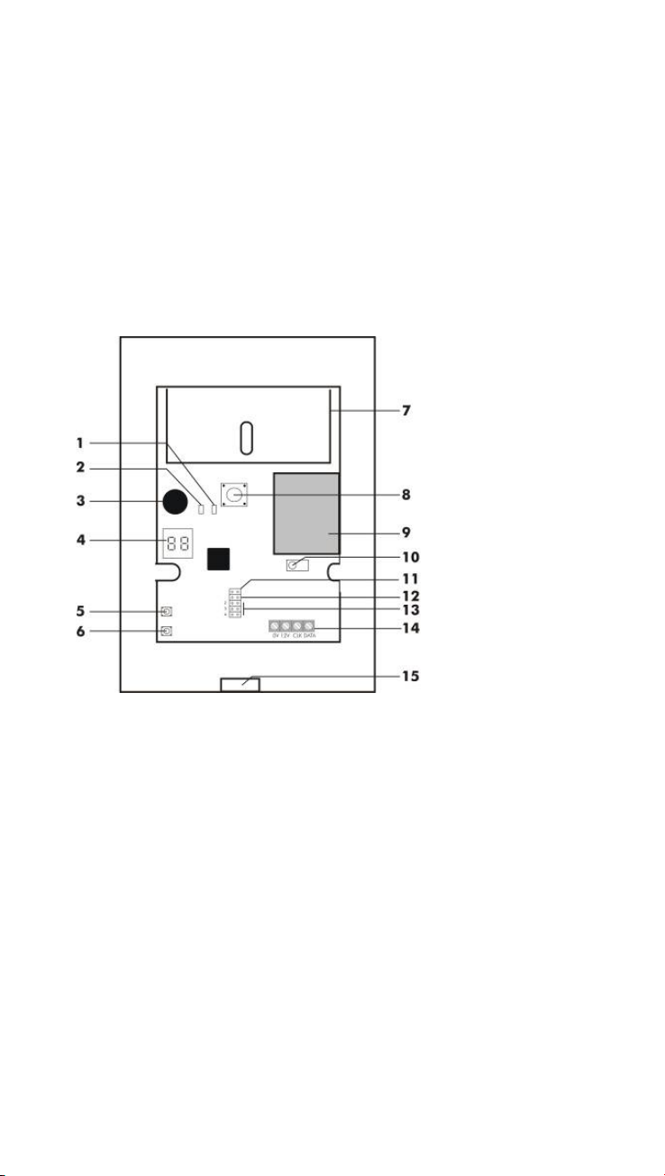
2. Beschreibung der Komponenten
1 Fehler-LED (Fail)
2 OK-LED (Pass)
3 Signalgeber
4 Display
5 Taster „Wählen“ (Select)
6 Taster „Löschen“ (Delete)
7 Antenne
8 Sabotageschalter
9 Funkplatine
10 Einlern-Sensor
11 Supervision-Steckbrücke
12 Jamming-Steckbrücke
(Funküberlagerung)
13 Adressierungs-Steckbrücke
14 BUS Anschluss
15 Kabelöffnung
3. Montage
1. Öffnen sie das Gehäuse der Funkerweiterung.
2. Lösen Sie die 3 Schrauben und entfernen Sie die
Platine von der Rückwand des Gerätes.
3. Verwenden Sie die Rückseite der Funkerweiterung zum
Anzeichnen der Bohrlöcher am gewünschten
Montageort. Bohren Sie entsprechende Löcher und
setzen Sie passende Dübel in die Bohrlöcher ein.
4. Führen Sie die Kabel des 4-Draht-BUS durch die
Öffnung auf der Rückseite des Moduls.
2
Page 3
5. Schrauben Sie die Gehäuserückseite mit passenden
Schrauben an den gewünschten Montageort und
setzen Sie die Platine wieder ein.
6. Verschließen Sie das Erweiterungsmodul nachdem Sie
die Verdrahtung und Programmierung vorgenommen
haben.
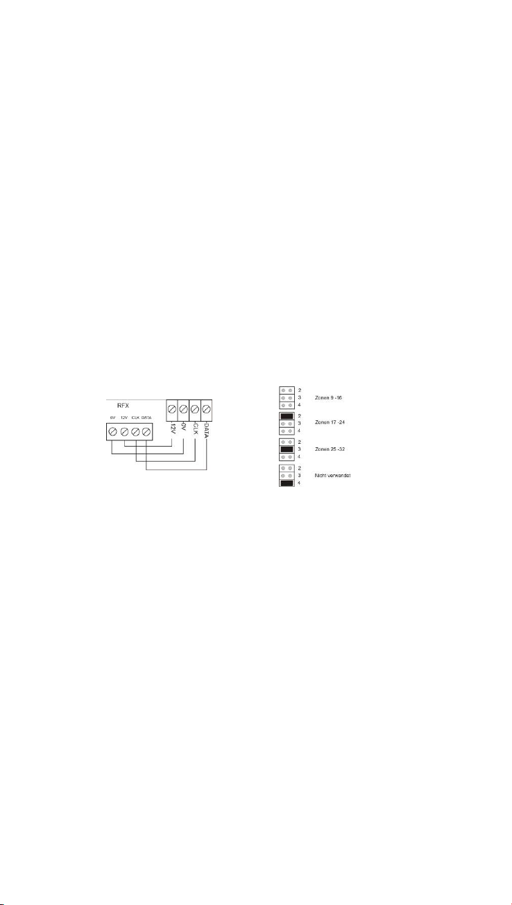
4. Verdrahtung
Am Daten-BUS werden, wie in der Installationsanleitung der
Zentrale beschrieben, die 4 Kabel vom Kommunikationsbus der
Zentrale angeschlossen. Weitere Module werden parallel an
diesen BUS angeschlossen. Die Unterscheidung der
Zonenbereiche wird durch die Adressierung der Module
vorgenommen (siehe Bild rechts unten). Beachten Sie bitte,
dass während der Anschlussarbeiten die Alarmzentrale
spannungsfrei sein muss.
Alarmzentrale
BUS
5. Programmierung
Um das Erweiterungsmodul in den Lernmodus zu bringen,
muss die 12V Gleichspannungsversorgung angeschlossen
werden (vom BUS oder separate Versorgung). Sobald alle
Melder im das Modul eingelernt sind, werden diese dauerhaft
gespeichert, auch wenn die Spannungsversorgung entfernt
wird.
Sobald die Spannungsversorgung angelegt wird, erscheint als
Erstes die Meldung „88“ im Display.
Um den Lernmodus zu betreten öffnen Sie einfach den
Sabotagekontakt (Frontabdeckung abnehmen) und drücken Sie
anschließend auf die Taste „SELECT“. Das Display zeigt nun
„- -„. Das Modul befindet sich nun im Lernmodus.
3
Page 4

HINWEIS:
Sie müssen den Lernmodus des Erweiterungsmoduls erst
verlassen, bevor Sie die Spannungsversorgung wieder
entfernen.
5.1 Einlernen von Funkkomponenten
1. Bringen Sie das Erweiterungsmodul in den Lernmodus,
wenn dies noch nicht erfolgt ist.
2. Stellen Sie sicher, dass die LED der einzulernenden
Funkkomponente auf den Einlern-Sensor, mit einem
maximalen Abstand von 100 mm, zeigt.
3. Aktivieren Sie die Funkkomponente (wenn nötig durch
Auslösen des Sabotagekontaktes). Dabei muss die
LED auf den Einlern-Sensor des Erweiterungsmoduls
gerichtet sein.
Das Erweiterungsmodul gibt einen Doppelton aus,
wenn die Funkkomponente erfolgreich eingelernt
wurde. Bei eingelernten Melder wird nun links die
Signalsträrke (max. 9) und rechts die Kanalnummer
angezeigt. Der Kanal wird automatisch zugewiesen.
Ein eingelernter Überfallmelder oder eine
Fernbedienung zeigt die Anzahl der eingelernten
Komponenten durch die Anzeige „
„ abwechselnd
mit der Signalstärke.
Kann die Funkkomponente nicht eingelernt werden, so
gibt das Erweiterungsmodul einen Einfachton aus.
4. Wiederholen Sie die Schritte 2 und 3 zum Einlernen
weiterer Funkkomponenten. Beachten Sie, dass max. 8
zusätzliche Funkfernbedienungen oder Überfallmelder
eingelernt werden können.
5.2 Zuordnung von Funkmeldern
1. Bringen Sie das Erweiterungsmodul in den Lernmodus.
2. Drücken Sie die Taste „SELECT“ solange, bis die
gewünschte Zonennummer angezeigt wird. Blinkt die
Anzeige, so ist die Zone frei. Ist die Anzeige dauerhaft,
so ist diese Zone belegt.
3. Führen Sie nun die Schritte 2 und 3 wie unter Abschnitt
„Einlernen von Funkkomponenten“ durch.
5.3 Löschen von Funkmeldern
1. Bringen Sie das Erweiterungsmodul in den Lernmodus.
2. Drücken Sie die Taste „SELECT“ solange, bis die
gewünschte Zonennummer angezeigt wird.
4
Page 5

3. Drücken Sie die Taste „DELETE“ für ca. 4 Sekunden.
Es ertönt ein Doppelton, und somit ist der Melder
gelöscht.
5.4 Löschen von sonstigen Komponenten
1. Bringen Sie das Erweiterungsmodul in den Lernmodus.
2. Drücken Sie die Taste „SELECT“ solange, bis „
Display angezeigt wird.
3. Drücken Sie die Taste „DELETE“ für ca. 4 Sekunden.
Es ertönt ein Doppelton, und somit sind alle
Funkfernbedienungen, Überfallmelder und gelöscht.
6. Betriebshinweise
6.1 Anzeige der Signalstärke
1. Bringen Sie das Erweiterungsmodul in den Lernmodus.
2. Drücken Sie die Taste „SELECT“ bis die gewünschte
Zonennummer oder die Funkfernbedienungs/Überfallmelder-Nummer angezeigt wird. Beide LEDs
auf der Platine sollten aus sein.
3. Aktivieren Sie die entsprechende Funkkomponente. Die
grüne LED (Pass) zeigt, dass die Signalstärke
ausreichend ist. Die rote LED (Fail) zeigt an, dass die
Signalstärke unzureichend ist. Im Display wird
Signalstärke und Zonennummer abwechselnd
angezeigt.
“ im
6.2 Jamming
Durch Setzen der Steckbrücke „Jamming“ (Funküberlagerung)
wird diese Funktion aktiviert. Als Jamming-Signal wird ein
Signal bezeichnet, dass auf der gleichen Frequenz wie die
Funkkomponente sendet, und stark genug ist, das Signal der
Funkkomponente für mindestens 30 Sekunden zu verdrängen.
6.3 Supervision
Durch Setzen der Steckbrücke „Supervision“ wird diese
Funktion aktiviert. Die Funkerweiterung meldet einen Melder als
fehlerhaft, wenn diese im unscharfen Zustand für mehr als 2
Stunden von diesem Melder kein Signal erhält. Im scharfen
Zustand wird sofort Alarm an die Zentrale gemeldet.
6.4 Melder-Batterie schwach
Wenn im Funkmelder die Batterieleistung nachlässt, so meldet
der Melder dies and die Funkerweiterung, welche ein Signal an
die Alarmzentrale abgibt.
5
Page 6

7. Technische Daten
Zonen
8 Funkzonen
Betriebs-
12 V DC
spannung
Sonst. Funk-
komponenten
Anzeige
Funkdaten
Max. 8 Stück
Zwei 7Segmentanzeigen
868,6625
MHz
Stromauf-
nahme
Gewicht
Abmaße
(HXBXT)
max. 55 mA
330 g
220x135x45 mm
6
Page 7

1. Main features
• 8 programmable zones
• tamper monitoring
• duplex-antenna technology
• simple connection using 4-wire BUS
• compatible to TERXON M / MX
• 868MHz FM security frequency
2. Main features
1 Error LED (Fail)
2 OK LED (Pass)
3 Detector
4 Display
5 Select button
6 Delete button
7 Antenna
8 Tamper switch
9 Radio PCB
10 Learn sensor
11 Supervision jumper
12 Jamming jumper(radio
interference)
13 Addressing jumper
14 BUS Connection
15 Cable Entry
3. Installation
1. Open the housing of the radio expansion.
2. Release the 3 screws and remove the PCB from the
rear wall of the unit.
3. Use the rear of the radio expansion unit to draw the
boreholes at the required assembly location. Bore the
appropriate holes and insert the correct dowel pins into
then.
4. Insert the cable of the 4-wire BUS through the opening
on the rear of the module.
7
Page 8
5. Screw the rear of the housing with the correct screws
onto the required assembly location and re-insert the
PCB.
6. Make sure that the alarm centre is disconnected from
the mains. Connect the 4-wire BUS correctly.
7. Once more close the 8-zone expansion module.
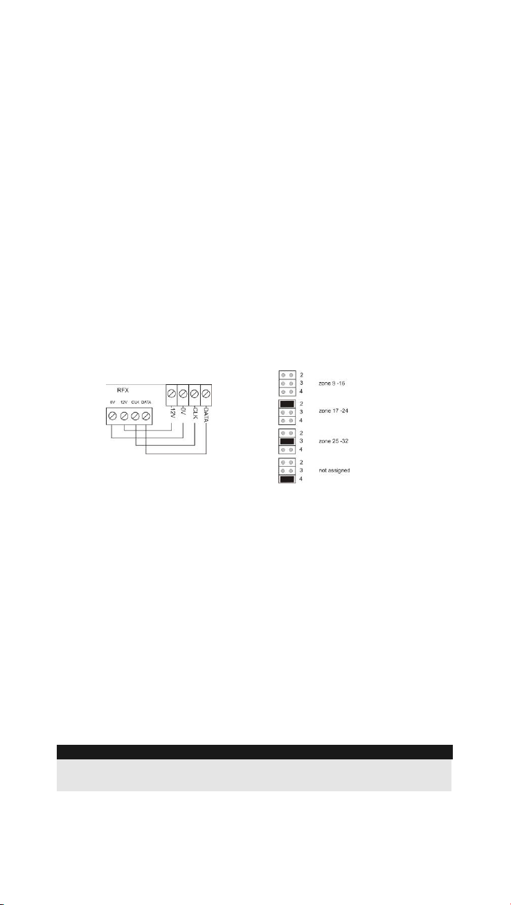
4. Wiring
The 4 wires from the communication bus of the central station
are connected at the data BUS as described in the installation
instructions of the alarm panel. Additional modules are
connected in parallel at this BUS. The zone ranges are
differentiated by the addressing of the modules. Please note
that during the connection work, the alarm panel must be
disconnected from the mains. Use the opening on the base of
the module to lay the cable.
alarm panel
BUS
5. Programming
To put the expansion module into learn mode, the 12V DC
supply must be connected (from the BUS or a separate supply).
As soon as all detectors have been programmed into the
module („taught“) they are stored permanently, even if there is a
power failure or the power is removed.
As soon as the power supply is connected, the first message
„88“ appears in the display.
To enter learn mode, simply open the tamper switch (remove
the front cover) and then press the „SELECT“ button. The
display now shows: “--“. The module is now in learn mode.
NOTE:
You must leave the learn mode of the expansion module before
removing the power supply.
8
Page 9

5.1 Teaching radio components
1. Put the expansion module into learn mode if you have
not already done so.
2. Make sure that the LED of the radio components to be
taught points to the learn sensor at a maximum
distance of 100 mm.
3. Activate the radio components (when necessary by
releasing the tamper switch). The LED must thereby
point to the learn sensor of the expansion module.
The expansion module emits a double beep when the
radio component has been successfully taught.
Detectors that have been taught now show the signal
strength on the left (max. 9) and the channel number on
the right. The channel is assigned automatically.
A taught panic alarm or remote control shows the
number of learnt components by displaying„
alternately to the signal strength.
If the radio component can not be taught then the
expansion module emits a single beep.
4. Repeat steps 2 and 3 to teach additional radio
components. Please observe that a maximum of 6 radio
remote controls or panic alarms can be taught.
5.2 Assigning detectors to particular zones
1. Put the expansion module into learn mode.
2. Press the „SELECT“ button until the required zone is
displayed. If the display flashes then the zone is not
assigned (free). If the display is constant then the zone
is assigned.
3. Now carry out steps 2 and 3 as described in „Teaching
radio components“.
„
5.3 Deleting detectors
1. Put the expansion module into learn mode.
2. Press the „SELECT“ button until the required zone is
displayed.
3. Press the „DELETE“ button for approx. 4 seconds. A
double beep is emitted and the detector is deleted.
5.4 Deleting remote controls
These components can not be deleted individually. To delete a
component, all radio remote controls and panic alarms must be
deleted.
9
Page 10

1. Put the expansion module into learn mode.
2. Press the „SELECT“ button until „
3. Press the „DELETE“ button for approx. 4 seconds. A
double beep is emitted and all radio remote controls
and panic alarms are thereby deleted.
“ is displayed.
6. Operation
6.1 Displaying the signal strength
1. Put the expansion module into learn mode.
2. Press the „SELECT“ button until the required zone
number or the radio remote control/panic alarm number
is displayed. Both LEDs on the PCB should now be off.
3. Activate the appropriate radio components. The green
LED (Pass) indicates that there is sufficient signal
strength. The red LED (Fail) indicates that there is
insufficient signal strength. The signal strength and
zone number are displayed alternately.
6.2 Jamming
Bridging the „Jamming“ pin (radio interference)activates this
function. A jamming signal is a signal that transmits at the same
frequency as the radio component and that is strong enough to
displace the signal from the radio component for at least 30
seconds.
6.3 Supervision
Bridging the „Supervision“ pin activates this function. The radio
expansion unit reports a detector as being faulty when it no
longer receives a signal from this detector for more than 2
hours.
6.4 Weak detector battery
If the battery power in the radio detector is weak then it reports
this to the radio expansion unit and this then passes on the
report to the alarm centre.
10
Page 11

7. Technical data
8 wireless
Zones
zones
Voltage
12 V DC
supply
Remote
controls
Display
Radio data
8 maximal
2 x 7
segment
display
868,6625
MHz
Power
consumption
Weight
Dimensions
(WxHxD)
max. 55 mA
330 g
220x135x45 mm
11
Page 12

1. Principales caractéristiques
• 8 zones programmables
• Equipée d’une surveillance anti-sabotage
• Antenne en technologie duplex
• Raccordement aisé par bus 4 fils
• Compatible avec TERXON M / MX
• Fréquence Security 868 MHz FM
2. Composants
1 DEL d’affichage de défaillance
(Fail)
2 DEL d’affichage d’un bon
fonctionnement (Pass)
3 Emetteur de signaux
4 Afficheur
5 Touche de sélection (Select)
6 Touche de suppression
(Delete)
7 Antenne
8 Interrupteur anti-sabotage
9 Platine radio
10 Détecteur d’apprentissage
11 Strap enfichable de
supervision
12 Strap enfichable de brouillage
(interférence)
13 Strap enfichable d’adressage
14 Connecteur BUS
15 Ouverture le câble
3. Montage
1. Ouvrir le boîtier de l’extension radio.
2. Desserrer les 3 vis et retirer la platine du panneau
arrière de l’appareil.
3. Utiliser la face arrière de l’extension radio pour tracer
les trous à percer sur le site de montage souhaité.
Percer les trous correspondants et introduire les
chevilles qui conviennent dans ces derniers.
12
Page 13

4. Introduire le câble à 4 fils du bus par l’ouverture située
en face arrière du module.
5. A l’aide de vis adéquates, visser le panneau arrière du
boîtier sur le site de montage souhaité et réintroduire la
platine.
6. Veiller à ce que la centrale soit hors tension. Raccorder
correctement le bus 4 fils.
7. Refermer le module d’extension 8 zones.
4. Raccordement
Les 4 câbles du bus de communication de la centrale sont
raccordés au niveau du bus de données, comme indiqué dans
les instructions d’installation de la centrale. Les autres modules
sont raccordés en parallèle sur ce bus. L’adressage des
modules permet de distinguer les secteurs de zones. Tenir
compte du fait que la centrale d’alarme est hors tension lors
des travaux de raccordement. Pour poser les câbles, utiliser
également l'ouverture située en face inférieure du module.
Centrale d´ alarme
BUS
5. Programmation
Configuration du mode d’apprentissage
L’alimentation en 12 V c.c. (par le bus ou séparée) doit être
raccordée pour permettre le passage du module d’extension en
mode d’apprentissage. A l’issue de l’introduction de tous les
détecteurs dans le module, ces derniers sont enregistrés de
manière durable et ne sont pas perdus lors d’une coupure de
courant.
En présence d'alimentation électrique, l'afficheur indique
d'abord « 88 ».
Pour passer en mode d’apprentissage, il suffit d’ouvrir le
contact anti-sabotage (retirer le cache avant) et de presser la
touche de sélection. L’afficheur indique maintenant « - -». A
présent, le module est en mode d'apprentissage.
13
Page 14

INDICATION:
Il convient de quitter le mode d’apprentissage du module, avant
de mettre de nouveau hors tension.
5.1 Apprentissage des composants radio
1. Faire passer le module d’extension en mode
d’apprentissage, si ce n’est pas encore le cas.
2. S’assurer que la DEL des composants radio objets de
l’apprentissage soit orientée vers le capteur
d’apprentissage et se trouve à pas plus de 100 mm de
celui-ci.
3. Activer le composant radio (le cas échéant, en
déclenchant le contact anti-sabotage). Lors de cette
opération, la DEL doit être orientée vers le capteur
d’apprentissage. Le module d’extension émet une
double tonalité, à la réussite de l'apprentissage du
composant radio. L’intensité du signal (9 maxi.) et le
numéro du canal doivent être affichés respectivement à
gauche et à droite, à l’issue de l’apprentissage du
détecteur. L’affectation du canal est automatique. Un
détecteur anti-agression ayant fait l’objet d’un
apprentissage ou une télécommande indique le nombre
de composants ayant fait l’objet d’un apprentissage, en
affichant tout à tour «
» et l’intensité du signal.
Dans l’impossibilité d’apprentissage du composant, le
module d’extension émet une seule tonalité.
4. Répéter les étapes 2 et 3 en vue de l’apprentissage de
composants radio supplémentaires. Noter qu'un
maximum de 6 télécommandes radio ou détecteurs
anti-agression peuvent faire l'objet d'un apprentissage.
5.2 Affectation de détecteurs à certaines zones
1. Faire passer le module d’extension en mode
d’apprentissage.
2. Presser la touche de sélection jusqu’à affichage du
numéro de zone souhaité. Un clignotement de
l'affichage indique que la zone est libre. Si l’affichage
ne clignote pas, la zone concernée est occupée.
3. Exécuter maintenant les étapes 2 et 3, comme indiqué
au paragraphe « Apprentissage de composants radio ».
14
Page 15

5.3 Suppression de détecteurs
1. Faire passer le module d’extension en mode
d’apprentissage.
2. Presser la touche de sélection jusqu’à affichage du
numéro de zone souhaité.
3. Presser la touche de suppression pendant env. 4
secondes. Une double tonalité retentit et le détecteur
est donc supprimé.
5.4 Suppression de télécommandes radio
Ces composants ne peuvent pas être supprimés séparément.
La suppression d’un composant nécessite la suppression de
toutes les télécommandes radio et de tous les détecteurs antiagression.
1. Faire passer le module d’extension en mode
d’apprentissage.
2. Presser la touche de sélection jusqu’à ce que l’afficheur
indique «
».
3. Presser la touche de suppression pendant env. 4
secondes. Une double tonalité retentit et la suppression
de toutes les télécommandes radio et de tous les
détecteurs anti-agression est donc complète.
6. Opération
6.1 Affichage de l’intensité du signal d’un détecteur
1. Faire passer le module d’extension en mode
d’apprentissage.
2. Presser la touche de sélection jusqu’à afficher le
numéro de zone ou celui de la télécommande radio ou
du détecteur anti-agression souhaité. Les deux DEL sur
la platine doivent être éteintes.
3. Activer le composant radio correspondant. La DEL
verte (Pass) indique que l'intensité du signal est
suffisante. La DEL rouge (Fail) indique que l'intensité
du signal est insuffisante. Sur l’afficheur, l’intensité du
signal et le numéro de zone apparaissent tour à tour.
6.2 Jamming
Le positionnement du strap enfichable de brouillage
(interférence) permet d’activer cette fonction. On appelle
« signal brouilleur » un signal émettant sur la même fréquence
que le composant radio et qui est assez fort pour supprimer le
15
Page 16

signal du composant radio concerné pendant 30 secondes au
moins.
6.3 Supervision
Le positionnement du strap enfichable de supervision permet
d’activer cette fonction. L’extension radio signale un détecteur
comme étant défectueux, si elle ne reçoit pas de signal de ce
dernier pendant plus de 2 heures.
6.4 Pile de détecteur quasiment épuisée
Si la puissance de la pile diminue dans le détecteur radio, ce
dernier le signale à l'extension radio qui le communique à la
centrale.
7. Fiche technique
Zones
8 zones sans
Alimentation
fil
12°V
Télécomman-
des radio
Affichage
Radio
8 sans fil
2 x 7
segments
868,6625
MHz
Con-
sommation
Poids
Dimensions
(LXHXP)
maxi. 55 mA
330 g
220x135x45 mm
16
Page 17

1. Hoofdkenmerken
• 8 programmeerbare zones
• met sabotagecontrole
• duplex-antenne-technologie
• eenvoudige aansluiting met behulp van 4-draads BUS
• compatibel met Terxon M / MX
• 868MHz FM security-frequentie
2. Overzicht van de componenten
1 Fout-LED (fail)
2 OK-LED (pass)
3 Signaalgever
4 Display
5 Toets “Kiezen” (SELECT)
6 Toets “Wissen” (DELETE)
7 Antenne
8 Sabotageschakelaar
9 Radioprintplaat
10 Inlees-sensor
11 Supervision-geleiderbrug
12 Jamming-geleiderbrug
(stoorsignalen)
13 Adresserings-geleiderbrug
14 BUS aansluiting
15 Kabelopening
3. Montage
1. Open het huis van de draadloze uitbreiding.
2. Draai de 3 schroeven los en verwijder de printplaat van
de achterwand van het apparaat.
3. Gebruik de achterkant van de draadloze uitbreiding
voor het aftekenen van de boorgaten op de gewenste
montageplaats. Boor overeenkomstige gaten en plaats
passende pluggen in de boorgaten.
4. Steek de kabels van de 4-draads BUS door de opening
op de achterkant van de module.
17
Page 18

5. Schroef de achterkant van het huis met passende
schroeven op de gewenste montageplaats en plaats de
printplaat weer.
6. Let erop dat de centrale spanningsloos geschakeld is.
Sluit de 4-draads BUS goed aan.
7. Sluit de uitbreidingsmodule met 8 zones weer.
4. Aansluiting
alarmcentrale
BUS
5. Programmering
Om de uitbreidingsmodule in de leermodus te zetten, moet de
12V gelijkspanningsvoeding aangesloten worden (van de BUS
of aparte voeding). Zodra alle melders in de module ingelezen
zijn, worden deze permanent opgeslagen, ook als de
spanningsvoeding verwijderd wordt.
Zodra de spanningsvoeding aangesloten wordt, verschijnt als
eerste de melding “88” op het display.
Om toegang tot de leermodus te krijgen, opent u gewoon het
sabotagecontact (frontafdekking verwijderen) en druk
vervolgens op de toets “SELECT”. Het display toont nu: “- -“.
De module bevindt zich nu in de leermodus.
INDICATIE:
U moet de leermodus van de uitbreidingsmodule eerst verlaten,
voordat u de spanningsvoeding weer verwijdert.
5.1 Inlezen van draadloze componenten
1. Zet de uitbreidingsmodule in de leermodus, als dit nog
niet gebeurd is.
2. Zorg ervoor dat de LED van de in te lezen draadloze
component in de richting van de inlees-sensor wijst,
met een maximale afstand van 100 mm.
3. Activeer de draadloze componenten (indien nodig door
activeren van het sabotagecontact). Daarbij moet de
LED op de inlees-sensor van de uitbreidingsmodule
gericht zijn.
18
Page 19

De uitbreidingsmodule geeft een dubbel signaal af, als
de draadloze component met succes ingelezen werd.
Bij ingelezen melders wordt nu links de signaalsterkte
(max. 9) en rechts het kanaalnummer weergegeven.
Het kanaal wordt automatisch toegewezen.
Een ingelezen overvalmelder of een afstandsbediening
geeft het aantal ingelezen componenten door de
weergave „
„ afwisselend met de signaalsterkte
weer.
Kan de draadloze component niet ingelezen worden,
dan geeft de uitbreidingsmodule een enkelvoudig
signaal af.
4. Herhaal de stappen 2 en 3 voor het inlezen van andere
draadloze componenten. Let erop dat max. 6 draadloze
afstandsbedieningen of overvalmelders ingelezen
kunnen worden.
5.2 Toewijzing van melders aan bepaalde zones
1. Zet de uitbreidingsmodule in de leermodus.
2. Druk zo lang op de toets “SELECT” tot het gewenste
zonenummer weergegeven wordt. Knippert de
weergave, dan is de zone vrij. Is de weergave continu,
dan is de zone bezet.
3. Voer nu de stappen 2 en 3 zoals in de paragraaf
“Inlezen van draadloze componenten” uit.
5.3 Wissen van melders
1. Zet de uitbreidingsmodule in de leermodus.
2. Druk zo lang op de toets “SELECT” tot het gewenste
zonenummer weergegeven wordt.
3. Druk ca. 4 seconden op de toets “DELETE”. Er klinkt
een dubbel signaal en dan is de melder gewist.
5.4 Wissen van de draadloze afstandsbedieningen
Deze componenten kunnen niet afzonderlijk worden gewist. Om
een component te wissen, moeten alle draadloze
afstandsbedieningen en overvalmelders gewist worden.
1. Zet de uitbreidingsmodule in de leermodus.
2. Druk zo lang op de toets “SELECT” tot “
” in het
display weergegeven wordt.
3. Druk ca. 4 seconden op de toets “DELETE”. Er klinkt
een dubbel signaal en dan zijn alle draadloze
afstandsbedieningen en overvalmelders gewist.
19
Page 20

6. Betriebshinweise
6.1 Weergeven van de signaalsterkte van een melder
1. Zet de uitbreidingsmodule in de leermodus.
2. Druk op de toets “SELECT” tot het gewenste
zonenummer of het nummer van de draadloze
afstandsbediening/overvalmelder weergegeven wordt.
Beide LED’s op de printplaat moeten uit zijn.
3. Activeer de overeenkomstige draadloze componenten.
De groene LED (Pass) geeft aan dat de signaalsterkte
voldoende is. De rode LED (Fail) geeft aan dat de
signaalsterkte onvoldoende is. Op het display wordt
signaalsterkte en zonenummer afwisselend
weergegeven.
6.2 Jamming
Door het zetten van de geleiderbrug “Jamming” (stoorsignalen)
wordt deze functie geactiveerd. Jamming-signaal wordt een
signaal genoemd dat op dezelfde frequentie als de draadloze
componenten zendt en sterk genoeg is om het signaal van de
draadloze componenten minimaal 30 seconden te verdringen.
6.3 Supervision
Door het zetten van de geleiderbrug “Supervision” wordt deze
functie geactiveerd. De draadloze uitbreiding meldt een melder
als foutief als deze meer dan 2 uur geen signaal van deze
melder ontvangt.
6.4 Melder - batterij zwak
Als in uw draadloze melder het vermogen van de batterij
afneemt, dan meldt deze dit aan de draadloze uitbreiding en
deze meldt het weer aan de centrale.
20
Page 21

7. Technische gegevens
Zones
8 draadloze
zones
Spannings-
voeding
12 V DC
Afstands-
bedieningen
Weergave
Radio-
gegevens
max. 8
2 x 7segmentdisplay
868,6625
MHz
Stroom-
opname
Gewicht
Afmetingen
(BXHXD)
max. 55 mA
330 g
220x135x45 mm
21
Page 22

1. Karakteristiske træk
• 8 programmerbare zoner
• Sabotageovervågning
• Dupleks-antenne-teknologi
• Nem tilslutning vha. 4-tråds BUS
• Kompatibel med Terxon M / MX
• 868 MHz FM sikkerheds-frekvens
2. Beskrivelse af komponenterne
1 Fejl-LED (Fail)
2 OK-LED'er (Pass)
3 Signalgiver
4 Display
5 Knap "Vælg" (Select)
6 Knap "Slet" (Delete)
7 Antenne
8 Sabotageafbryder
9 Radio-printkort
10 Indlærings-sensor
11 Supervision-jumper
12 Jamming-jumper
(radiooverlejring)
13 Adresserings-jumper
14 BUS-tilslutning
15 Kabelåbning
3. Montage
1. Åbn kabinettet af radioudvidelsen.
2. Løsn de 3 skruer og fjern printpladen fra apparatets
bagvæg.
3. Brug bagsiden af radioudvidelsen til at markere
borehullerne på det ønskede montagested. Bor de
tilsvarende huller og sæt plugs i borehullerne.
4. Stik kablet fra 4-tråds BUS'en gennem åbningen på
bagsiden af modulet.
5. Fastgør kabinettets bagside med passende skruer på
det ønskede monteringssted og isæt printkortet igen.
22
Page 23

6. Luk udvidelsesmodulet, når du har foretaget
ledningsføringen og programmeringen.
4. Ledningsføring
Tilslut de 4 kabler fra centralens kommunikations-BUS til dataBUS'en som beskrevet i centralens installationsvejledning.
Ekstra moduler tilsluttes parallelt til denne BUS. En skelnen
mellem zoneområderne foretages vha. adressering af
modulerne (se fig. forneden til højre). Vær opmærksom på, at
strømforsyningen til alarmcentralen skal være afbrudt under
arbejdet med tilslutningerne.
Alarmcentral
BUS
5. Programmering
12V jævnspændingsforsyningen skal tilsluttes (fra BUS eller
separat forsyning) for at bringe udvidelsesmodulet i
indlæringsmodus. Så snart alle meldere i modulet er indlært,
gemmes de permanent - også selvom spændingsforsyningen
frakobles.
Når spændingsforsyningen tilkobles, kommer meldingen "88"
straks i displayet.
For at komme i indlæringsmodus skal du åbne
sabotageafbryderen (tag frontafskærmningen af) og derefter
trykke på knappen "SELECT". Displayet viser nu "- -". Modulet
er i indlæringsmodus.
BEMÆRK:
Du skal forlade udvidelsesmodulets indlæringsmodus, inden du
frakobler spændingsforsyningen igen.
5.1 Indlæring af radiokomponenter
1. Bring udvidelsesmodulet i indlæringsmodus, hvis du
ikke har gjort det endnu.
23
Page 24

2. Sørg for, at LED'en på radiokomponenterne, der skal
indlæres, peger på indlæringssensoren med en maks.
afstand på 100 mm.
3. Aktivér radiokomponenterne (om nødvendigt ved at
udløse sabotageafbryderen). LED'en skal være rettet
imod indlæringssensoren på udvidelsesmodulet.
Udvidelsesmodulet afgiver et dobbelt lydsignal, når
radiokomponenterne er blevet indlært korrekt. For de
indlærte meldere vises nu signalstyrken (maks. 9) til
venstre og kanalnummeret til højre. Kanalen tildeles
automatisk.
En indlært overfaldsmelder eller fjernbetjening viser
skiftevist antallet af indlærte komponenter vha.
visningen "
" og signalstyrken.
Hvis radiokomponenterne ikke kan indlæres, afgiver
udvidelsesmodulet en enkelt lyd.
4. Gentag trin 2 og 3 for at indlære yderligere
radiokomponenter. Vær opmærksom på, at der maks.
kan indlæres 8 yderligere fjernbetjeninger eller
overfaldsmeldere.
5.2 Tildeling af radiomeldere
1. Udvidelsesmodulet skal være i indlæringsmodus.
2. Tryk på knappen "SELECT", indtil det ønskede
zonenummer vises. Hvis visningen blinker, er zonen fri.
Hvis visningen ikke blinker, er zonen optaget.
3. Gennemfør nu trin 2 og 3 som beskrevet i afsnittet
"Indlæring af radiokomponenter".
5.3 Sletning af radiomeldere
1. Udvidelsesmodulet skal være i indlæringsmodus.
2. Tryk på knappen "SELECT", indtil det ønskede
zonenummer vises.
3. Tryk på knappen "DELETE" i ca. 4 sekunder. Der
kommer et dobbelt lydsignal; dermed er melderen
slettet.
5.4 Sletning af andre komponenter
1. Udvidelsesmodulet skal være i indlæringsmodus.
2. Tryk på knappen "SELECT", indtil "
" vises i
displayet.
3. Tryk på knappen "DELETE" i ca. 4 sekunder. Der
kommer et dobbelt lydsignal; dermed er alle
fjernbetjeninger og overfaldsmeldere slettet.
24
Page 25

6. Driftsanvisninger
6.1 Visning af signalstyrken
1. Udvidelsesmodulet skal være i indlæringsmodus.
2. Tryk på knappen "SELECT", indtil det ønskede
zonenummer eller fjernbetjenings-/overfaldsmeldernummeret vises. Begge LED'er på printkortet skal være
slukket.
3. Aktivér de pågældende radiokomponenter. Den grønne
LED (Pass) viser, at signalstyrken er kraftig nok. Den
røde LED (Fail) viser, at signalstyrken ikke er kraftig
nok. I displayet vises signalstyrken og zonenummeret
skiftevist.
6.2 Jamming
Ved at sætte jumperen "Jamming" til (radiooverlejring) aktiveres
denne funktion. Et jamming-signal er et signal, der sender på
samme frekvens som radiokomponenterne, og som er kraftigt
nok til at fortrænge radiokomponenternes signal i min. 30
sekunder.
6.3 Supervision
Ved at sætte jumperen "Supervision" til aktiveres denne
funktion. Radioudvidelsen melder, at en melder har en fejl, hvis
den i over 2 timer ikke modtager noget signal fra melderen, når
den ikke er tilkoblet. I tilkoblet tilstand meldes alarmen straks til
centralen.
6.4 Svagt batteri i melderen
Hvis batteriets ydelse i radiomelderen bliver svagere, melder
melderen det til radioudvidelsen, som derefter afgiver et signal
til alarmcentralen.
25
Page 26

7. Tekniske data
Zoner
Andre
radiokom-
ponenter
Display
8 radiozoner
Maks. 8 stk.
To 7segmentdisplays
Driftsspænding
Strømforbrug
Vægt
12 V DC
Maks. 55 mA
330 g
Radiodata
868,6625
MHz
Mål (h x b x d)
220 x 135 x 45
mm
26
Page 27

1. Caratteristiche
• 8 zone programmabili
• Controllo manomissione
• Tecnologia antenna Duplex
• Collegamento semplice tramite BUS a 4 fili
• Compatibile con Terxon M / MX
• Frequenza di sicurezza 868MHz FM
2. Descrizione dei componenti
1 LED guasti (Fail)
2 LED OK (Pass)
3 Generatore di segnale
4 Display
5 Tasto „Seleziona“ (Select)
6 Tasto „Elimina“ (Delete)
7 Antenna
8 Interruttore manomissione
9 Scheda radio
10 Sensore di inizializzazione
11 Ponticello di supervisione
12 Ponticello jamming
(mascheramento radio)
13 Ponticello di indirizzamento
14 Collegamento BUS
15 Apertura per cavo
3. Montaggio
1. Aprire l'alloggiamento di ampliamento radio.
2. Allentare le 3 viti e rimuovere la scheda dalla parete
posteriore dell'apparecchio.
3. Utilizzare la parete posteriore del modulo di
ampliamento radio per contrassegnare i fori sul punto di
montaggio desiderato. Forare e inserire i tasselli
corrispondenti nei fori.
4. Inserire il cavo del BUS a 4 fili nell'apertura posta sul
lato posteriore del modulo.
27
Page 28

5. Avvitare il lato posteriore dell'alloggiamento sul luogo di
montaggio desiderato utilizzando le viti corrispondenti,
inserire quindi nuovamente la scheda.
6. Chiudere il modulo di ampliamento dopo aver eseguito
il cablaggio e la programmazione.
4. Cablaggio
Sul BUS dati vengono collegati, come descritto nelle istruzioni
per l'installazione della centralina, i cavi del bus di
comunicazione della centralina. Gli altri moduli vengono
collegati a questo BUS in parallelo. L'indirizzamento dei moduli
consente di contraddistinguere le zone (vedere immagine in
basso a destra). Durante i lavori di collegamento fare
attenzione a disinserire la tensione dalla centralina di allarme.
Centralina di allarme
BUS
5. Programmazione
Per impostare la modalità di inizializzazione sul modulo di
ampliamento occorre collegare l'alimentazione di tensione
continua 12V (dal BUS oppure alimentazione separata). Dopo
aver inizializzato tutti i rilevatori sul modulo, questi verranno
salvati in modo permanente anche in caso di disinserimento
della tensione.
Dopo aver inserito l'alimentazione della tensione, il display
visualizzerà dapprima il messaggio „88“.
Per avviare la modalità di inizializzazione, aprire semplicemente
il contatto antimanomissione (rimuovere la copertura frontale) e
premere quindi il tasto „SELECT“. Il display visualizza ora „- -„.
Il modulo si trova ora in modalità inizializzazione.
AVVERTENZA:
Prima di disinserire nuovamente la tensione, uscire dalla
modalità di inizializzazione del modulo di ampliamento.
28
Page 29

5.1 Inizializzazione dei componenti radio
1. Se non ancora eseguito, impostare la modalità di
inizializzazione sul modulo di ampliamento.
2. Accertarsi che il LED dei componenti radio da
inizializzare indichi il sensore a una distanza massima
di 100 mm.
3. Attivare il componente radio (se necessario, far scattare
il contatto antimanomissione). In questo caso, il LED
deve essere rivolto in direzione del sensore di
inizializzazione del modulo di ampliamento.
Se il componente radio è stato inizializzato in modo
corretto, il modulo di ampliamento emetterà un segnale
doppio. Una volta inizializzato, il rilevatore mostra a
sinistra la potenza del segnale (max. 9) e a destra il
numero di canale. Il canale viene assegnato in
automatico.
Dopo aver inizializzato un rilevatore antirapina o un
telecomando, l'indicazione „
„, alternata alla potenza
del segnale, mostrerà il numero dei componenti
inizializzati.
Se non è possibile inizializzare il componente radio, il
modulo di ampliamento emette un suono semplice.
4. Per inizializzare altri componenti radio ripetere le fasi 2
e 3. Notare che è possibile inizializzare max. 8
telecomandi radio supplementari o rilevatori antirapina.
5.2 Assegnazione dei rilevatori radio
1. Impostare la modalità di inizializzazione sul modulo di
ampliamento.
2. Premere il tasto „SELECT“ sino a visualizzare il numero
di zona desiderato. Se il display lampeggia, la zona è
libera. Se il display è immobile, la zona è assegnata.
3. Eseguire ora la fase 2 e 3 come descritto nella sezione
„Inizializzazione dei componenti radio“.
5.3 Eliminazione dei rilevatori radio
1. Impostare la modalità di inizializzazione sul modulo di
ampliamento.
2. Premere il tasto „SELECT“ sino a visualizzare il numero
di zona desiderato.
3. Premere il tasto „DELETE“ per ca. 4 secondi. Viene
emesso un suono doppio che indica l'eliminazione del
rilevatore.
29
Page 30

5.4 Eliminazione di altri componenti
1. Impostare la modalità di inizializzazione sul modulo di
ampliamento.
2. Premere il tasto „SELECT“ sino a visualizzare „
3. Premere il tasto „DELETE“ per ca. 4 secondi. Viene
emesso un suono doppio che indica l'eliminazione di
tutti i telecomandi radio e i rilevatori antirapina.
“.
6. Istruzioni per l'uso
6.1 Visualizzazione della potenza del segnale
1. Impostare la modalità di inizializzazione sul modulo di
ampliamento.
2. Premere il pulsante „SELECT“ sino a visualizzare il
numero di zona desiderato oppure il numero di
rilevatore antirapina/telecomando radio. I due LED sulla
scheda devono essere inattivi.
3. Attivare i componenti radio corrispondenti. Il LED
(Pass) verde indica se la potenza del segnale è
sufficiente. Il LED rosso (Fail) indica se la potenza del
segnale è insufficiente. Il display mostra a intermittenza
la potenza del segnale e il numero della zona.
6.2 Jamming
Per attivare questa funzione inserire il ponticello „Jamming“
(mascheramento radio). Per segnale Jamming si intende un
segnale, inviato alla stessa frequenza dei componenti radio,
abbastanza potente a sostituire il segnale dei componenti radio
per almeno 30 secondi.
6.3 Supervisione
Per attivare questa funzione inserire il ponticello „Supervisione“.
Il modulo di ampliamento radio segnala un rilevatore guasto se
questo, disattivo, non riceve alcun segnale per oltre due ore dal
rilevatore. Una volta attivo, il modulo invierà immediatamente
un allarme alla centralina.
6.4 Batteria rilevatore scarica
Se la prestazione della batteria nel rilevatore radio diminuisce, il
rilevatore invia una comunicazione al modulo di ampliamento
radio che invia un segnale alla centralina di allarme.
30
Page 31

7. Dati tecnici
Zone
8 zone radio
Tensione
12 V DC
d'esercizio
Altri
componenti
radio
Indicatore
Dati radio
Max. 8 pezzi
Due indicatori
da 7 segmenti
868,6625 MHz
Assorbimento
di corrente
Peso
Dimensioni
(AxLxP)
max. 55 mA
330 g
220x135x45
mm
31
Page 32

Dieses Gerät erfüllt die Anforderungen der EU-Richtlinie:
1995/5/EG Richtlinie über Funkanlagen und Telekommunikationseinrichtungen und die gegenseitige Anerkennung ihrer
Konformität.
This product complies with the requirements of the EU directive:
1995/5/EU Directive on radio and telecommuni-cations terminal
equipment and the mutual recognition of their conformity.
Die Konformitätserklärung ist zu beziehen unter:
The declaration of conformity can be ordered from:
ABUS Security-Center GmbH & Co. KG
86444 Affing
GERMANY
www.abus-sc.eu
info@abus-sc.eu
32
 Loading...