

Page 1

ADSL ROUTER
Quick Installation Guide
M73-APO07-110
Page 2
Parts Names and functions
Rear view of the ADSL ROUTER
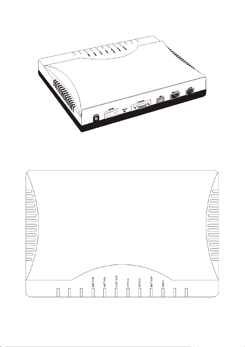
LED Indicator
Top View of ADSL ROUTER (LEDs)
- 1 -
Page 3
LED
Description
POWER
ADSL_PWR
ETH_LNK
ETH_ACT
ADSL_AUTO
ADSL_LINK
ADSL_ERR
Router Power on/off Indicator
ADSL Module Power on/off Indicator
Ethernet Link Indicator
Ethernet Active Indicator
ADSL Auto Connection Indicator
ADSL Data Link Indicator
ADSL Link Error Indicator
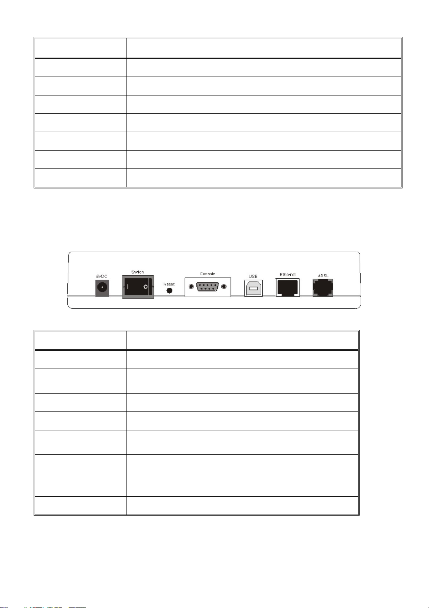
Connectors on the Rear Panel
The following table describes the function of the connectors and switches on the ADSL
ROUTER rear panel. See the following illustration for the location of the connectors
described in the following table.
Connectors on the rear panel
Connector Label Connector Description
5VDC
5VDC Input Power Connector
Switch
Reset
Console
USB
Ethernet
ADSL
POWER ON/OFF SWITCH
System Reset.
Connects this device to the serial port on your PC.
USB INPUT PORT
Connects to the Ethernet port on your PC using
the Non Hub Ethernet cable supplied with your
unit, or LAN hub using a straight-through cable.
Connects this device to the wall jack.
- 2 -
Page 4

Setting Up the Hardware Environment
Connecting All Cables to the Network
Perform the following procedures to set up the ADSL ROUTER.
Connect the power adapter to the port labeled
Step 1
device.
Connect the Ethernet cable.
Step 2
One PC – ADSL Router (direct connection)
If your only have
a hub. For a single Ethernet-equipped PC, use the "non-hub" twisted-pair crossover cable to
connect the ADSL ROUTER Ethernet port to the Ethernet port on your computer.
Home Network – ADSL Router (connection through Ethernet Switch/Hub)
one PC
, you can connect your ADSL ROUTER to the PC directly without
on the rear panel of this
5VDC
If your ADSL ROUTER is connected to a
cable (not provided) to connect your ADSL ROUTER Ethernet port to an available port on
your home network Ethernet hub.
Connect the ADSL cable to the ADSL ROUTER. Connect the ADSL ROUTER to
Step 3
the ADSL line with the provided telephone cable.
home network
- 3 -
, you may use a standard Ethernet
Page 5

Connect one end of RS-232 cable to any free COM port in your system; Connect
Step 4
the other end to “Console” port on the rear panel of the ADSL router.
Powering On the ADSL ROUTER
Connect the power adapter to your ADSL ROUTER by plugging one end of the
Step 1
power supply into an appropriate electrical outlet and the other end into port
labeled
Note: To power off he ADSL ROUTER, just unplug the power supply cable from the ADSL
ROUTER rear panel POWER connector.
Once your ADSL ROUTER is powered up, check to make sure the Power LED is
Step 2
red and ON.
on the rear panel of the device.
5VDC
Step 3
If the Power LED is not lit, immediately turn off all power to the ADSL ROUTER.
- 4 -
Page 6

INTERNET ACCESS
Router Mode/ IP over ATM (RFC1577)
(1) Run the “
ADSL Router xx Configuration UtilityÆConfiguration Utility
(2) Select a PC COM port available on your computer used to connect to the ADSL Router’s
“
Console
(3) Check “
(4) Click “
(5) Enter “
service provider.
(6) Usually
sure if this is your case, if yes, remember to select “
(7) Enter the VPI and VCI numbers. Typically VPI is set to “0”.
router.exe
” port.
Router Protocol
Properties
ADSL IP
Ethernet IP addresses
” file saved in the configuration utility. (Go to
” button.
”, “
Gateway IP
” and select “
were not provided by service providers. Check to make
IP over ATM
”, and “
Subnet Mask
”.
” addresses provided by your
Enable NAT function
Start ÆProgram
.)
.”
Æ
- 5 -
Page 7

(8) Click “OK” to go to “
for future use. Then click “
(9) Click “
Configure
you. Expect a minor delay for configuration.
Select Config
”.
Next
” button. The configure utility will automatically setup the router for
Bridge mode/RFC1483 bridge
” menu. Or click “
Save As File
” to save the settings
(1) Run the “
ADSL Router xx Configuration UtilityÆConfiguration Utility
(2) Select a PC COM port available on your computer used to connect to the ADSL Router’s
“
Console
(3) Click “
(4) Select Mode “
(5) Click “
router.exe
” port.
” button.
Next
Properties
” file saved in the configuration utility. (Go to
Bridge
” button.
” and select “
RFC1483 Bridge
- 6 -
”.
Start ÆProgram
.)
Æ
Page 8

(6) Enter VPI and VCI numbers. Then click “OK”.
(7) Check “
(8) Click “
LLC Encapsulation
” followed by “
Next
” or “
VC Based Route
Configure
” or “
VC Based Bridge
”.
”. Configure utility will automatically setup the
router for you. Expect a minor delay for the router configuration.
(9) Click “
”. Now you have finished ADSL Router configuration. The ADSL Router
Finish
will handshake with ADSL central site equipment (DSLAM) and try to make the ADSL
connection.
- 7 -
 Loading...