

Page 1

WI-2P
Dual Socket 604 Workstation Board
User’s Manual
4200-0303-22
Rev. 1.00
Page 2

Copyright and Warranty Notice
The information in this document is subject to change without notice and does not
represent a commitment on part of the vendor, who assumes no liability or
responsibility for any errors that may appear in this manual.
No warranty or representation, either expressed or implied, is made with respect to the
quality, accuracy or fitness for any particular part of this document. In no event shall
the manufacturer be liable for direct, indirect, special, incidental or consequential
damages arising from any defect or error in this manual or product.
Product names appearing in this manual are for identification purpose only and
trademarks and product names or brand names appearing in this document are
property of their respective owners.
This document contains materials protected under International Copyright Laws. All
rights reserved. No part of this manual may be reproduced, transmitted or transcribed
without the expressed written permission of the manufacturer and authors of this
manual.
WI-2P
Page 3

Contents
Chapter 1. Introduction .................................................... 1-1
1.1. Features & Specifications....................................................... 1-1
1.2. Package Checklist................................................................... 1-3
1.3. Layout Diagram...................................................................... 1-4
Chapter 2. Hardware Setup.............................................. 2-1
2.1. Precautions .............................................................................2-1
2.2. Installing the Workstation Board ...........................................2-2
2.3. Install Xeon CPU and Heatsink ............................................. 2-3
2.4. System Memory .....................................................................2-4
2.4.1. Memory Configuration Table................................... 2-4
2.4.2. Installing and Removing Memory Modules............. 2-4
2.5. Connectors, Headers, and Switches .......................................2-6
2.5.1. ATXPWR1, ATX12V1: EPS12V Power Connectors
.................................................................................. 2-6
2.5.2. FAN1~6: FAN Connectors....................................... 2-7
2.5.3. CCMOS1: CMOS Memory Clearing Header........... 2-8
2.5.4. FPIO1: Front Panel Switches and Indicators Header
.................................................................................. 2-9
2.5.5. FDC1, IDE0/IDE1 Connectors:.............................. 2-10
2.5.6. PCI1 ~ PCI5: PCI Card Slots: ................................2-11
2.5.7. 6CHAUD1: 5.1-Channel Audio Interface Header .2-12
2.5.8. USB1/USB3: Additional USB Ports Headers ........2-13
2.5.9. CD1, AUX1: Internal Audio Connector................. 2-14
2.5.10. IR1: Infrared Device Header .................................. 2-15
2.5.11. Back Panel Connectors: .......................................... 2-16
2.5.12. J4: RAID Card Connector ...................................... 2-17
2.5.13. JP4: Terminator/Raptor II RAID Card Selector .....2-18
2.5.14. SCSI1/SCSI2: Ultra 320 SCSI Channels Connector
................................................................................ 2-19
User’s Manual
Page 4

Chapter 3. BIOS Setup...................................................... 3-1
3.1. Main Menu .............................................................................3-2
3.2. Advanced Menu .....................................................................3-6
3.2.1. Advanced BIOS Features .........................................3-6
3.2.2. Advanced Chipset Features ......................................3-9
3.2.3. Integrated Peripherals ............................................. 3-11
3.2.4. Power Management Setup ...................................... 3-16
3.2.5. PnP/PCI Configurations.......................................... 3-20
3.3. Security Menu ......................................................................3-22
3.4. PC Health Menu ................................................................... 3-23
3.5. Clk/Misc. Menu.................................................................... 3-25
3.6. Exit Menu ............................................................................. 3-26
Chapter 4. Driver Installation .......................................... 4-1
4.1. Setup Items ............................................................................. 4-2
4.2. Installing Ultra320 SCSI Controller....................................... 4-3
4.2.1. Installing Windows 2000 with an Ultra320 SCSI
Controller.................................................................. 4-3
4.2.2. Installing the Driver when Windows 2000 is Already
Installed..................................................................... 4-3
4.2.3. Changing SCSI Boot Controllers in Windows 2000
.................................................................................. 4-4
Appendix A. Trouble Shooting ........................................... A-1
Appendix B. How to Get Technical Support ..................... B-1
WI-2P
Page 5

Introduction 1-1
Chapter 1. Introduction
1.1. Features & Specifications
CPU
• Supports Dual Intel
Xeon processor (603-pin or 604-pin)
Chipset
• Intel
• Intel
• Intel
E7505 chipset supports 400MHz/533MHz Front Side Bus
82801DB (ICH4) supports PCI 2.2, Ultra DMA100 IDE
protocol
82870P2 (P64H2) supports PCI-X 66/100MHz
Memory
• Six 184-pin DIMM sockets support DDR200/DDR266 RAM module
• Supports up to 12GB (Registered ECC)
• Supports up to 8GB (Unbuffered, Non ECC)
LAN
• Onboard Intel 82545EM (Kenai-64) Gigabit Ethernet Controller
• 10/100/1000 Mb Ethernet
Graphics
• AGP8x/4x AGP Pro
SCSI
• Adaptec AIC-7902, Dual channel Ultra 320 controller on board.
• Support Adaptec SCSI RAID card - 2015S (Raptor II) or “Terminator”
System BIOS
• AWARD Plug and Play BIOS supports APM, DMI, and ACPI
• Write-Protect Anti-Virus function by AWARD BIOS
• 4M-bit Flash ROM
I/O Slot
• 2 PCI 33MHz/32bit PCI slots
• 1 PCI-X 100MHz/64bit slot
User’s Manual
Page 6

1-2 Chapter 1
• 2 PCI-X 100MHz/64bit slots (JP4 pin-1 and pin-2 shorted for Adaptec
Terminator RAID card -- Default)
or 2 PCI 66MHz/64bit (JP4 pin-2 and pin-3 shorted Adaptec Raptor II
RAID card)
• 1 AGP Pro slot
Multi I/O Functions
• 1 floppy port
• 2 channels of bus master IDE ports supporting up to four Ultra
DMA100 devices
• 1 parallel port, 2 serial ports and 1 game port
• PS/2 keyboard and PS/2 mouse connectors
• Support 6 USB ports
• Support AC97, 5.1Channel (Option)
• Support S/PDIF (Option)
Miscellaneous
• 24-pin and 8-pin EPS 12V power connectors
• Extend ATX form factor (12” x 13”)
Specifications and information contained herein are subject to change
without notice.
WI-2P
Page 7

Introduction 1-3
1.2. Package Checklist
(1) WI-2P Workstation board
(1) Brief Installation Guide
(1) Driver & Utilities CD
(1) Ribbon cable for (1) 3.5” floppy disk drive
(2) Ribbon cables for master and slave IDE drives
(1) 68-pin LVD/SE SCSI cable with terminator for 5 Ultra 320 SCSI devices
(2) CPU Retention Mechanism
(2) Retention Clips for 603-pin CPU
(2) Retention Clips for 604-pin CPU
(1) I/O Shield
(1) 2-port USB 2.0 cable
User’s Manual
Page 8
1-4 Chapter 1
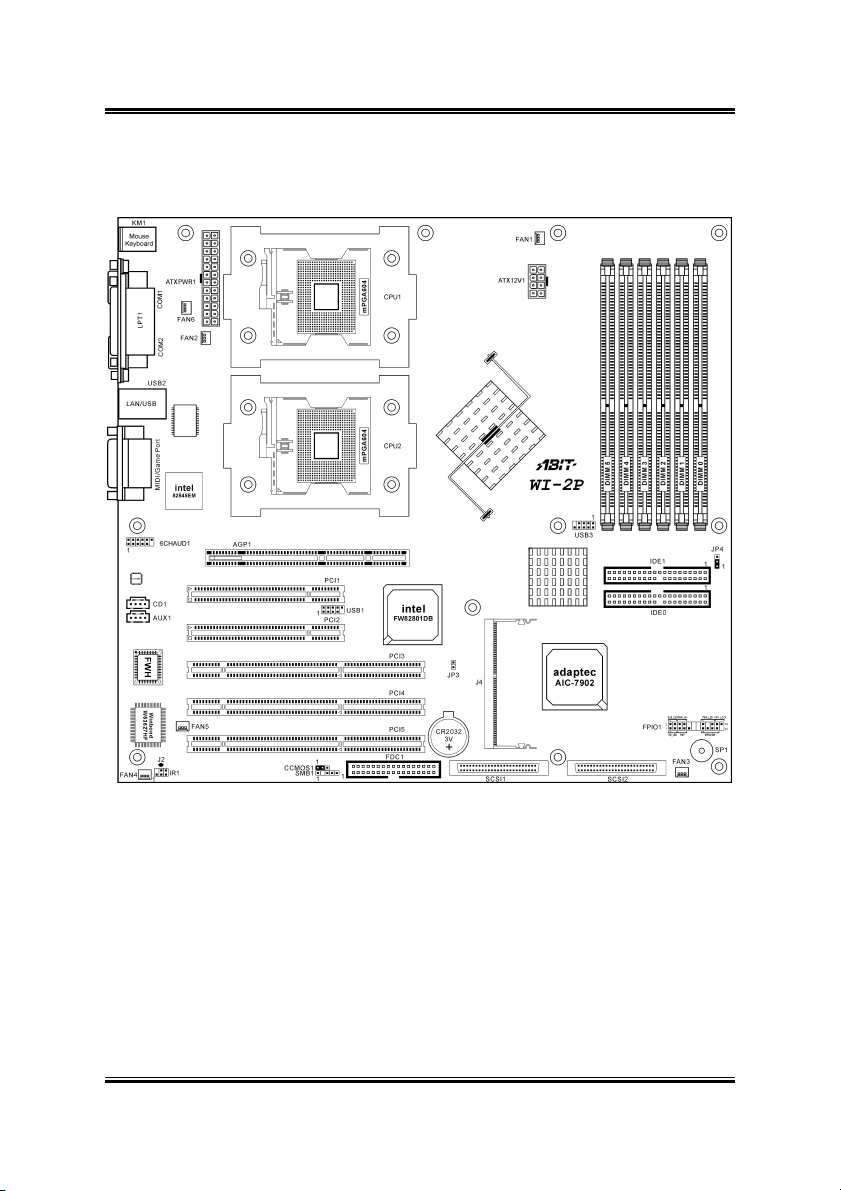
1.3. Layout Diagram
WI-2P
Page 9

Introduction 1-5
Jumpers Description Default Setting
CCMOS1 CMOS Clear Pins 1-2 Closed (Normal)
JP4 RAID Card Selector
(Terminator/Raptor II)
Connectors Description
6CHAUD1 Optional ABIT CA-20 Interface Connector
AGP1 Slot for AGP8x/4x AGP Pro Display Card
ATX12V1 8-pin EPS12V Power Connector
ATXPWR1 24-pin EPS12V Power Connector
CD1/AUX1 Internal Audio Sources Connectors
DIMM 0~5 DDR DIMM Slots
FAN1 CPU1 Fan Connector (Speed monitoring support)
FAN2 CPU2 Fan Connector (Speed monitoring support)
FAN3 System Fan Connector (Speed monitoring support)
FAN4/5/6
FDC1 Floppy Disk Drive Connector
FPIO1 Front Panel Switches & Indicators Headers
IDE0/IDE1 Hard Disk Drive Connectors
IR1 Optional Infrared Devices Connector
J4 Adaptec Zero Channel RAID Card Connector
JP3 Chassis Intrusion Header
PCI1/2 PCI 33MHz/32bit
PCI3 PCI-X 100MHz/64bit
PCI4/PCI5
SCSI1 Ultra 320 SCSI Channel A Connector
SCSI2 Ultra 320 SCSI Channel B Connector
SMB1 System Management Bus (SMBus) Header
USB1/USB3 Additional USB Ports Connectors
System Fan Connector (No speed monitoring support in BIOS
menu)
PCI-X 100MHz/64bit (JP4 pin1-2 shorted)
or PCI 66MHz/64bit (JP4 pin2-3 shorted)
Pins 1-2 Closed
(“Terminator” RAID Card)
User’s Manual
Page 10

1-6 Chapter 1
WI-2P
Page 11

Hardware Setup 2-1
Chapter 2. Hardware Setup
2.1. Precautions
Please pay attention to the following precautions before setting up any hardware.
1. Always switch off the power supply and unplug the power cord from the wall
outlet before installing the board or changing any settings.
2. Ground yourself properly by wearing a static safety wrist strap before removing
the board from the antistatic bag.
3. Hold the board by its edges. Avoid touching any component on it.
4. Avoid touching module contacts and IC chips
5. Place the board on a grounded antistatic surface or on the antistatic bag that came
with the board.
User’s Manual
Page 12
2-2 Chapter 2
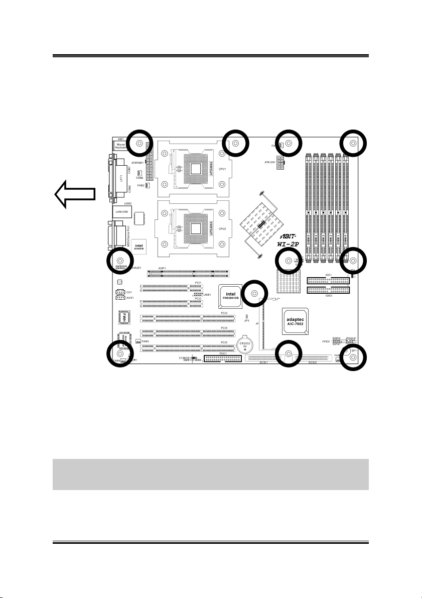
2.2. Installing the Workstation Board
Before installing the workstation board, exam your chassis to ensure this workstation
board fits into it. Your chassis should support Extend ATX form factor.
1. Face the side of the I/O ports toward the rear part of the chassis.
2. Locate the screw holes on the workstation board and the chassis base.
3. Place all the studs or spacers needed on the chassis base and have them tightened.
4. Line up all the screw holes on the board with those studs or spacers on the chassis.
5. Tightens all the screw holes.
ATTENTION: To prevent shorting the PCB circuit, please REMOVE the metal studs
or spacers if they are already secured on the chassis base and are without
mounting-holes on the workstation board to align with.
WI-2P
Page 13
Hardware Setup 2-3
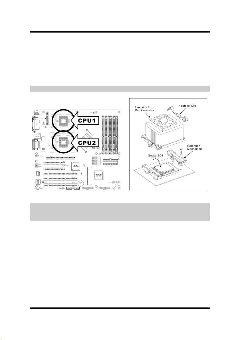
2.3. Install Xeon CPU and Heatsink
This workstation board provides you two Socket-604 sockets to install Intel Xeon
CPU. The CPU you bought should have a kit of heatsink and cooling fan bundled
together. If that’s not the case, buy one specially designed for Xeon Socket 604 CPU.
Please refer to the diagram shown below to install CPU and heatsink.
NOTE: This workstation board also supports the Xeon CPU of 603-pin package.
NOTE: The diagram shown here is for reference only. Your retention mechanism
may not be exactly the same as this type. Please follow the installation instruction of
the heatsink you bought.
User’s Manual
Page 14
2-4 Chapter 2
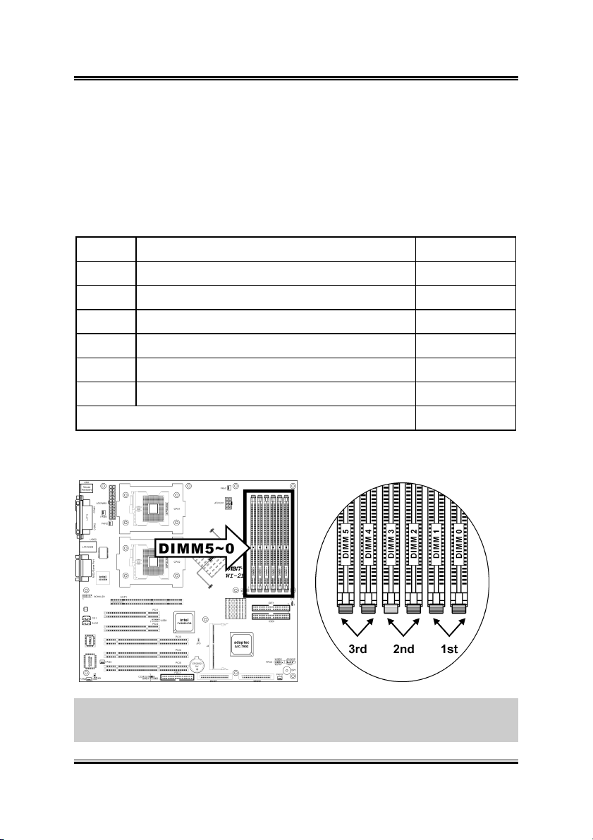
2.4. System Memory
This workstation board provides six 184-pin Double Data Rate (DDR) Dual Inline
Memory Module (DIMM) slots for Registered ECC DIMM modules with memory
expansion size up to 12GB.
2.4.1. Memory Configuration Table
DIMM Registered ECC DIMM Module Total Memory
0 128MB, 256MB, 512MB, 1GB, 2GB 128MB ~ 2GB
1 128MB, 256MB, 512MB, 1GB, 2GB 128MB ~ 2GB
2 128MB, 256MB, 512MB, 1GB, 2GB 128MB ~ 2GB
3 128MB, 256MB, 512MB, 1GB, 2GB 128MB ~ 2GB
4 128MB, 256MB, 512MB, 1GB, 2GB 128MB ~ 2GB
5 128MB, 256MB, 512MB, 1GB, 2GB 128MB ~ 2GB
Total System Memory 256MB ~ 12GB
2.4.2. Installing and Removing Memory Modules
ATTENTION: Populate the DDR DIMMs in-order and in-pair (of the same type
and size) by starting from DIMM0~DIMM1, DIMM2~DIMM3, to DIMM4~DIMM5.
The System may hang or appear unstable if the DIMM ordering is not followed.
WI-2P
Page 15

Hardware Setup 2-5
Power off the computer and unplug the
AC power cord before installing or
removing memory modules.
1. Locate the DIMM slot on the
workstation board.
2. Hold two edges of the DIMM
module carefully, keep away of
touching its connectors.
3. Align the notch key on the module with the rib on the slot.
4. Firmly press the module into the slots until the ejector tabs at both sides of the slot
automatically snaps into the mounting notch. Do not force the DIMM module in
with extra force as the DIMM module only fit in one direction.
5. To remove the DIMM modules, push the two ejector tabs on the slot outward
simultaneously, and then pull out the DIMM module.
ATTENTION: As the static electricity can damage the electronic components of the
computer or optional modules, make sure you are discharged of static electricity by
touching a grounded metal object briefly before starting these procedures.
User’s Manual
Page 16
2-6 Chapter 2
2.5. Connectors, Headers, and Switches
All the connectors, headers and switches mentioned here are depending on your
system configuration. Some features you may (or may not) have to connect or to
configure depending on the peripherals you have connected.
WARNING: Always power off the computer and unplug the AC power cord before
adding or removing any peripheral or component. Failing to so may cause severe
damage to your workstation board and/or peripherals. Plug in the AC power cord only
after you have carefully checked everything.
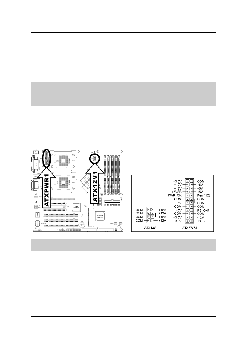
2.5.1. ATXPWR1, ATX12V1: EPS12V Power Connectors
These two connectors connect to EPS12V power supply. This workstation board
requires an EPS12V power supplier with 460W capacity at least for Pentium 4 Xeon
CPU system.
NOTE: The auxiliary 12V power (ATX12V1) is necessary to support Intel Xeon
CPUs. Failing to provide such extra power will result in the system’s booting failure.
WI-2P
Page 17
Hardware Setup 2-7
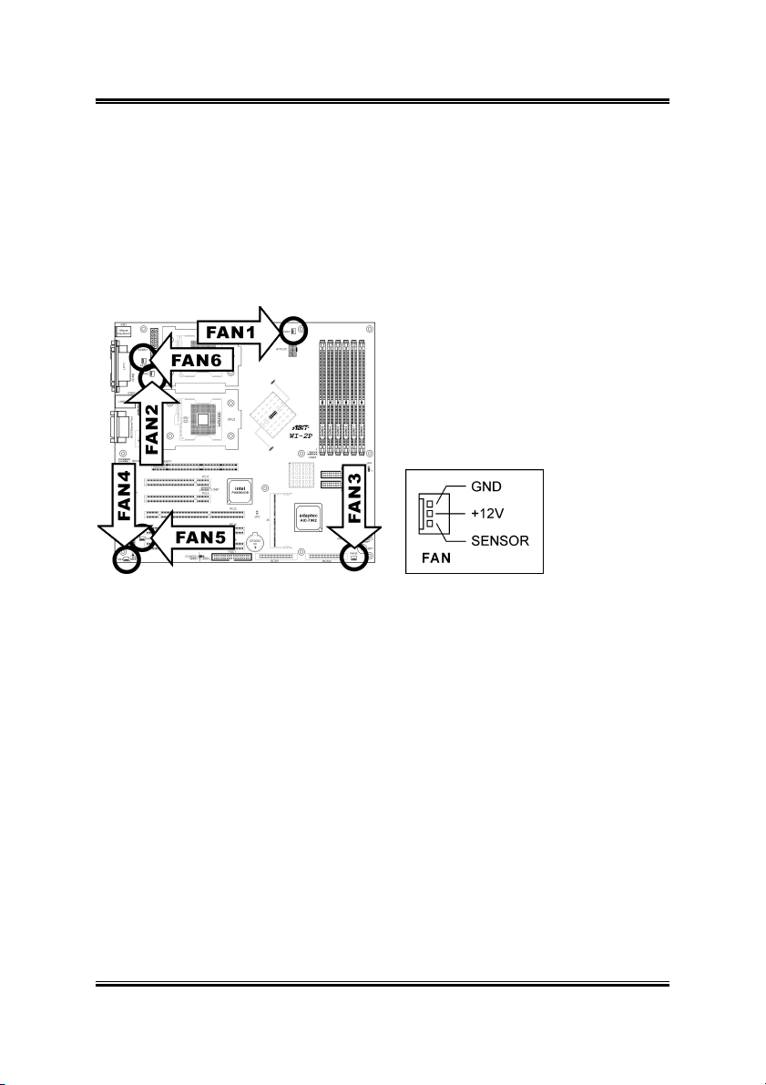
2.5.2. FAN1~6: FAN Connectors
• FAN1: CPU1 Fan
• FAN2: CPU2 Fan
• FAN3: System Fan
• FAN4~FAN6: System Fan (No speed monitoring support in BIOS menu)
User’s Manual
Page 18
2-8 Chapter 2
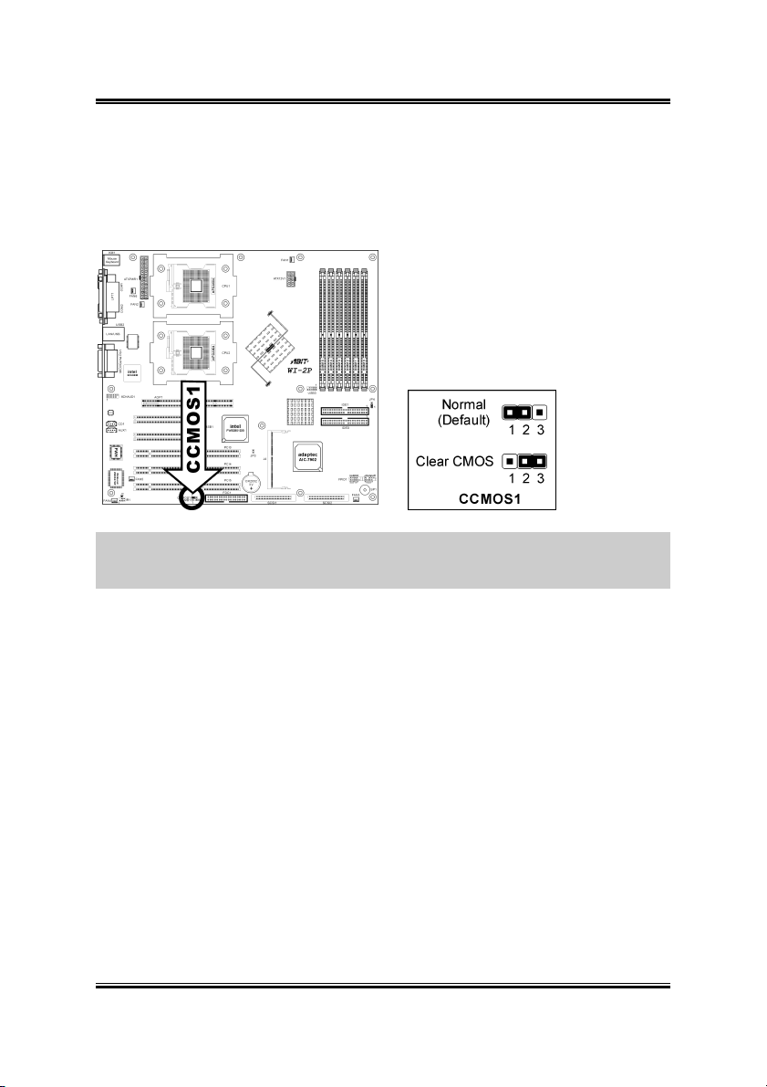
2.5.3. CCMOS1: CMOS Memory Clearing Header
This header uses a jumper cap to clear the CMOS memory. Short pin-2 and pin-3 only
when you want to clear the CMOS memory. The default setting is pin-1 and pin-2
shorted for normal operation.
ATTENTION: Turn the system power off first (including the +5V standby power)
before clearing the CMOS memory. Failing to do so may cause your system to work
abnormally or malfunction.
WI-2P
Page 19
Hardware Setup 2-9
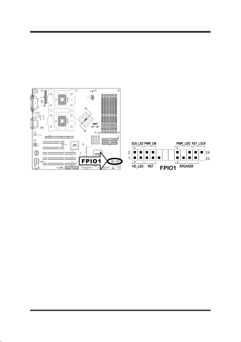
2.5.4. FPIO1: Front Panel Switches and Indicators Header
This header is used for connecting switches and LED indicators on the chassis front
panel.
Watch the power LED pin position and orientation. The mark “+” align to the pin in
the figure below stands for positive polarity for the LED connection.
• HD_LED: Connects to the HDD LED cable of chassis front panel.
• RST: Connects to the Reset Switch cable of chassis front panel.
• SPEAKER: Connects to the System Speaker cable of chassis.
• SUS_LED: Connects to the Suspend LED cable (if there is one) of chassis
front panel.
• PWR_ON: Connects to the Power Switch cable of chassis front panel.
• PWR_LED: Connects to the Power LED cable of chassis front panel.
• KEY_LOCK: Connects to the Keylock cable (if there is one) of chassis front
panel.
User’s Manual
Page 20
2-10 Chapter 2
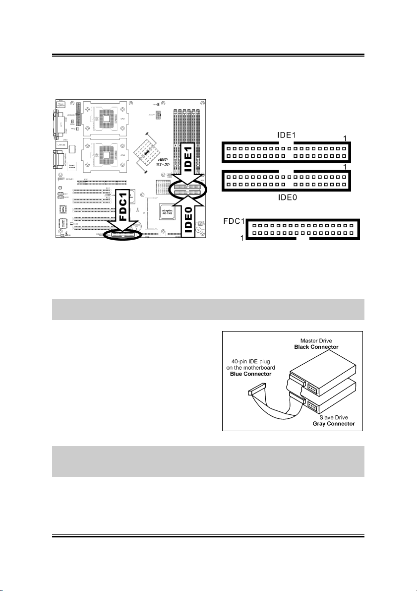
2.5.5. FDC1, IDE0/IDE1 Connectors:
The FDC1 connector connects up to two floppy drives with a 34-wire, 2-connector
floppy cable. Connect the single end at the longer length of ribbon cable to the FDC1
on the board, the two connectors on the other end to the floppy disk drives connector.
Generally you need only one floppy disk drive in your system.
NOTE: The red line on the ribbon cable must be aligned with pin-1 on both the FDC1
port and the floppy connector.
Each of the IDE port connects up to two
IDE drives at Ultra ATA/100 mode by one
40-pin, 80-conductor, and 3-connector Ultra
ATA/66 ribbon cables.
Connect the single end (blue connector) at
the longer length of ribbon cable to the IDE
port of this board, the other two ends (gray
and black connector) at the shorter length of
the ribbon cable to the connectors of your
hard drives.
NOTE: Make sure to configure the “Master” and “Slave” relation before connecting
two drives by one single ribbon cable. The red line on the ribbon cable must be
aligned with pin-1 on both the IDE port and the hard-drive connector.
WI-2P
Page 21
Hardware Setup 2-11
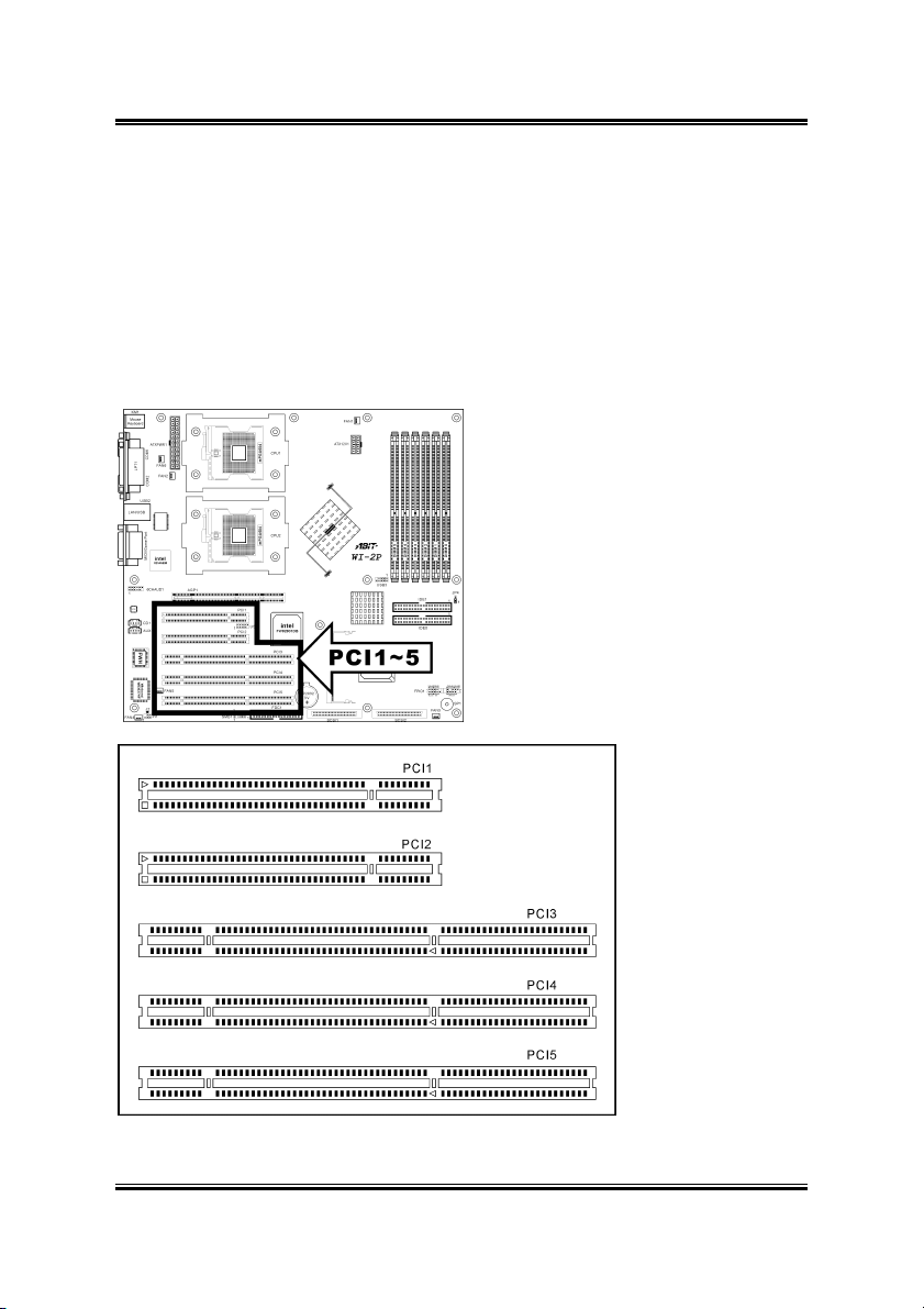
2.5.6. PCI1 ~ PCI5: PCI Card Slots:
PCI1/PCI2: PCI 33MHz/32bit
PCI3: PCI-X 100MHz/64bit
PCI4/PCI5: PCI-X 100MHz/64bit (JP4 pin-1 and pin-2 shorted for Adaptec
Terminator RAID card -- Default)
or PCI 66MHz/64bit (JP4 pin-2 and pin-3 shorted Adaptec Raptor II
RAID card)
User’s Manual
Page 22

2-12 Chapter 2
2.5.7. 6CHAUD1: 5.1-Channel Audio Interface Header
This header provides 5.1-channel audio output through optional ABIT CA-20
interface.
To enable the audio function on optional CA-20 interface, use the extension cable
packed with CA-20 to connect both the 6CHAUD1 headers on CA-20 and this board.
WI-2P
Page 23

Hardware Setup 2-13
2.5.8. USB1/USB3: Additional USB Ports Headers
These headers each provide two additional USB ports connection.
Pin Pin Assignment Pin Pin Assignment
1 VCC 2 VCC
3 Data0 - 4 Data1 -
5 Data0 + 6 Data1 +
7 Ground 8 Ground
9 NC 10 NC
To enable the USB function on optional CA-20 interface, use the extension cable
packed with CA-20 to connect the JP1 header on CA-20 and the USB1 header on this
board.
User’s Manual
Page 24
2-14 Chapter 2
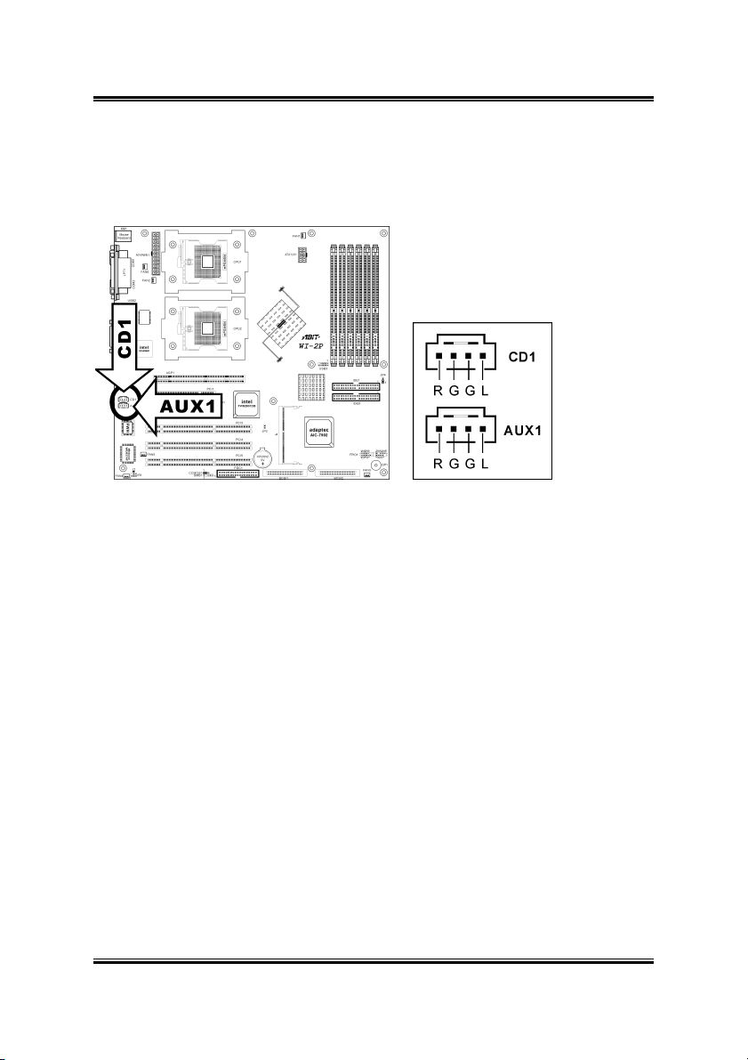
2.5.9. CD1, AUX1: Internal Audio Connector
These connectors connect to the audio output of internal CD-ROM drive or add-on
audio card.
WI-2P
Page 25

Hardware Setup 2-15
2.5.10. IR1: Infrared Device Header
This header connects to an optional IR device attached to chassis. This workstation
board supports standard IR transfer rates.
User’s Manual
Page 26

2-16 Chapter 2
2.5.11. Back Panel Connectors:
• Mouse: PS/2 mouse connector.
• Keyboard: PS/2 keyboard connector.
• LPT: Parallel port connector.
• COM1/COM2: Serial port connector
• LAN: Local Area Network connector.
Left LED Right LED Definition
Off Off No Connection
Green Off Link
Green Blink Orange Active
• USB: Universal Serial Bus connector.
• MIDI/GAME Port: Joystick, game pad, MIDI or other simulation hardware
devices connector.
• Line Out: Audio output jack.
• Line In: Audio input jack.
• Mic In: Microphone input jack.
WI-2P
Page 27

Hardware Setup 2-17
2.5.12. J4: RAID Card Connector
The J4 connector can be used to setup a RAID system by installing an optional
Adaptec RAID card - 2015S (Raptor II) or the latest “Terminator” to this connector.
User’s Manual
Page 28

2-18 Chapter 2
2.5.13. JP4: Terminator/Raptor II RAID Card Selector
This header uses a jumper cap to select the RAID card from Terminator to Raptor II.
Short pin-2 and pin-3 only when using Adaptec Raptor II RAID card.
The default setting is pin-1 and pin-2 shorted for Adaptec Terminator RAID card.
WI-2P
Page 29
Hardware Setup 2-19
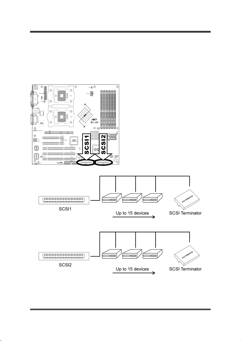
2.5.14. SCSI1/SCSI2: Ultra 320 SCSI Channels Connector
Both SCSI1 and SCSI2 connectors provide two 68-pin Ultra 320 SCSI channels. Each
channel supports up to 15 devices (ID0~ID15) on a standard Ultra 320 SCSI LVD
(Low Voltage Differential) cable, configuration up to 12 meters. In a point-to-point
arrangement, cabling can extend 25 meters.
Each device has its own individual SCSI ID number, but none of the devices
connected can use ID7, which is reserved for SCSI controller.
User’s Manual
Page 30

2-20 Chapter 2
In order to prevent signal loss, a 68-pin twisted
ribbon cable (LVD) with external SCSI terminator is
necessary to connect Ultra 320 SCSI hard drive to
this workstation board. All termination jumpers on
the SCSI devices must be removed when using the
external SCSI terminator.
IMPORTANT: Each channel should have only one
type of SCSI standard. A mixed setup with different
standard on the same channel will decrease the
performance to the slowest device.
WI-2P
Page 31

BIOS Setup 3-1
Chapter 3. BIOS Setup
The BIOS is a program located in a Flash Memory chip on the workstation board.
This program will not be lost when you turn the computer off. This program is also
referred to as the boot program. It is the only channel the hardware circuit has to
communicate with the operating system. Its main function is to manage the setup of
the workstation board and interface card parameters, including simple parameters
such as time, date, hard disk drive, as well as more complex parameters such as
hardware synchronization, and device operating mode. The computer will operate
normally, or will operate at its best, only if all of these parameters are correctly
configured through the BIOS.
Don’t change the parameters inside the BIOS unless you fully understand its
meanings and consequences: The parameters inside the BIOS are used to setup the
hardware synchronization or the device-operating mode. If the parameters are not
correct, they will produce errors, the computer will crash, and sometimes you will not
even be able to boot the computer after it has crashed. We recommend that you do not
change the parameters inside the BIOS unless you are very familiar with them. If you
are not able to boot your computer anymore, please refer to the section “CMOS
Memory Clearing Header” in Chapter 2.
When you start the computer, the BIOS program controls it. The BIOS first operates
an auto-diagnostic test called POST (Power On Self Test) for all of the necessary
hardware. It then configures the parameters of the hardware synchronization, and
detects all of the hardware. After these tasks are completed, the operating system (OS)
give up control of the computer to the next level. Since the BIOS is the only channel
for hardware and software to communicate, it is the key factor for system stability,
and in ensuring that your system performs at its best. After the BIOS has achieved the
auto-diagnostic and auto-detection operations, it will display the following message:
PRESS DEL TO ENTER SETUP
NOTE: As the BIOS menu is being constantly improved to increase system stability
and performance; the BIOS screens in this manual may not completely match those of
your BIOS version.
User’s Manual
Page 32

3-2 Chapter 3
3.1. Main Menu
Date (mm:dd:yy)
This item allows you to set the date you specify (usually the current date) in the
format of [Month], [Date], and [Year]. Valid values are [Month]: January ~ December,
[Date]: 1 ~ 31, and [Year]: 1999 ~ 2099. Use the <Tab> or <Enter> key to move
between the fields.
Time (hh:mm:ss)
This item allows you to set the time you specify (usually the current time) in the
format of [Hour], [Minute], and [Second]. Valid values are [Hour]: 00 ~ 23, [Minute]:
00 ~ 59, and [Second]: 00 ~ 59. Use the <Tab> or <Enter> key to move between the
fields.
IDE Primary Master, IDE Primary Slave, IDE Secondary Master, and IDE
Secondary Slave
Move cursor to item “IDE Primary Master”, “IDE Primary Slave”, “IDE Secondary
Master” or “IDE Secondary Slave”, and then press <Enter> key to enter a sub-menu.
WI-2P
Page 33

BIOS Setup 3-3
IDE Primary/Secondary Master/Slave
IDE HDD Auto-Detection
This item allows you to detect the parameters of IDE drives by pressing the <Enter>
key. The parameters will automatically be shown on the screen.
IDE Primary Master
When set to [Auto], the BIOS will automatically check what kind of IDE drive you
are using. If you want to define your own drive by yourself, set it to [Manual] and
make sure you fully understand the meaning of the parameters. Refer to the manual
provided by the device manufacturer to get the settings right.
Access Mode
This item selects the mode to access your IDE devices. Leave this item to its default
[Auto] settings to let BIOS detects the access mode of your HDD and makes decision
automatically.
Capacity
This item automatically displays your HDD size. Note that this size is usually slightly
greater than the size given by a disk-checking program of a formatted disk.
NOTE: The following [Cylinder], [Head], [Precomp], [Landing Zone], and [Sector]
items are available when you set the item “IDE Primary Master” to “Manual”.
User’s Manual
Page 34

3-4 Chapter 3
Cylinder
When disks are placed directly above one another along the shaft, the circular vertical
“slice” consisting of all the tracks located in a particular position is called a cylinder.
You can set the number of cylinders for a HDD. The minimum number you can enter
is 0, the maximum number you can enter is 65535.
Head
This is the tiny electromagnetic coil and metal pole used to create and read back the
magnetic patterns on the disk (also called the read/write head). You can configure the
number of read/write heads. The minimum number you can enter is 0, the maximum
number you can enter is 255.
Precomp
The minimum number you can enter is 0, the maximum number you can enter is
65535.
Landing Zone
This is a non-data area on the disk's inner cylinder where the heads can rest when the
power is turned off. The minimum number you can enter is 0, the maximum number
you can enter is 65535.
Sector
The minimum segment of track length that can be assigned to stored data. Sectors
usually are grouped into blocks or logical blocks that function as the smallest units of
data permit. You can configure this item to sectors per track. The minimum number
you can enter is 0, the maximum number you can enter is 255.
WI-2P
Page 35

BIOS Setup 3-5
Drive A
This item sets the type of floppy drives installed.
[None]: No floppy drive installed
[360K, 5.25 in.]: 5.25-inch standard drive; 360KB capacity
[1.2M, 5.25 in.]: 5.25-inch AT-type high-density drive; 1.2MB capacity
[720K, 3.5 in.]: 3.5-inch double-sided drive; 720KB capacity
[1.44M, 3.5 in.]: 3.5-inch double-sided drive; 1.44MB capacity
[2.88M, 3.5 in.]: 3.5-inch double-sided drive; 2.88MB capacity
Halt On
This item determines whether the system stops if an error is detected during system
boot-up.
[All Errors]: The system-boot will stop whenever the BIOS detect a non-fatal error.
[No Errors]: The system-boot will not stop for any error detected.
[All, But Keyboard]: The system-boot will stop for all errors but keyboard error.
[All, But Diskette]: The system-boot will stop for all errors but disk error.
[All, But Disk/Key]: The system boot will stop for all errors but disk or keyboard
error.
Base Memory
This item displays the amount of base memory installed in the system. The value of
the base memory is typically 640K for system with 640K or more memory size
installed on the motherboard.
Extended Memory
This item displays the amount of extended memory detected during system boot-up.
Total Memory
This item displays the total memory available in the system.
User’s Manual
Page 36

3-6 Chapter 3
3.2. Advanced Menu
3.2.1. Advanced BIOS Features
CPU Hyper-Threading
Leave this item to its default setting to enable the simultaneous multi-threaded (SMT)
processor so as to make one physical processor looks like two logical processors to
the OS and applications.
WI-2P
Page 37

BIOS Setup 3-7
This option is for CPU with Hyper-Threading Technology only. For more information
on “Hyper-Threading Technology”, please visit Intel Web site at
http://www.intel.com/homepage/land/hyperthreading.htm
http://www.intel.com/design/chipsets/ht/
.
,
Quick Power On Self Test
When set to [Enabled], this item speeds up the Power On Self Test (POST) after
powering on the system. The BIOS shorten or skip some check during the POST.
Hard Disk Boot Priority
This item allows you to select the booting priority of hard disks.
First Boot Device / Second Boot Device / Third Boot Device / Boot Other
Device
Select the drive to boot first, second and third in the [First Boot Device], [Second
Boot Device], and [Third Boot Device] fields respectively. The BIOS will boot the
operating system according to the sequence of the drive selected. Set [Boot Other
Device] to [Enabled] if you wish to boot from another device other than these three
items.
Boot Up NumLock Status:
This item allows you to determine the default state of the numeric keypad. When set
to [On], the system boots up with NumLock on wherein the function of the numeric
keypad is the number keys. When set to [Off], the function of the numeric keypad is
the arrow keys.
Security Option
This option can be set to System or Setup. The default setting is Setup. After you have
created a password through PASSWORD SETTING, this option will deny access to
your system (System) or modification of computer setup (BIOS Setup) by
unauthorized users.
SYSTEM: When you choose System, a password is required each time the computer
boots up. If the correct password is not given, the system will not start.
SETUP: When you choose Setup, a password is required only when accessing the
BIOS Setup. If the correct password is not given, you can’t enter the BIOS setup
menu.
To disable security, select Set Supervisor Password at main menu and then you will
be asked to enter the password. Do not type anything and just press the <Enter> key
and it will disable security. Once security is disabled, the system will boot and you
can enter the BIOS setup menu freely
User’s Manual
Page 38

3-8 Chapter 3
NOTE: Don’t forget your password. If you forget the password, you will have to
open the computer case and clear all information in the CMOS before you can start up
the system. But by doing this, you will have to reset all previously set options.
MPS Version Control For OS:
This item specifies which version of MPS (Multi-Processor Specification) this
workstation board will use. The options are 1.1 and 1.4. The default setting is 1.4. If
you use an older OS for dual processor executing, please set this option to 1.1.
Small Logo(EPA) Show:
This item determines to show the EPA logo when booting.
WI-2P
Page 39

BIOS Setup 3-9
3.2.2. Advanced Chipset Features
DRAM Timing Control
This item controls the DRAM timing. Press <Enter> key to enter its menu.
DRAM Timing Selectable
This item sets the optimal timings for the following four items, depending on the
memory module you are using. The default setting “By SPD” configures these four
User’s Manual
Page 40

3-10 Chapter 3
items by reading the contents in the SPD (Serial Presence Detect) device. The
EEPROM on the memory module stores critical parameter information about the
module, such as memory type, size, speed, voltage interface, and module banks.
CAS Latency Time
This item controls the latency between the DRAM read command and the time that
the data becomes actually available.
ACT. to Precharge Delay
This item controls the number of DRAM clocks used for DRAM parameters.
DRAM RAS# to CAS# Delay
This item controls the latency between the DRAM active command and the read/write
command.
DRAM RAS# Precharge
This item controls the idle clocks after issuing a precharge command to the DRAM.
DRAM Data Integrity Mode
Two options are available: ECC and Non-ECC. The default setting is Non-ECC. This
option is used to configure the type of DRAM in your system. ECC is “Error
Checking and Correction”. Choose the ECC option only when your memory is ECC
type.
NOTE: When installed with Registered memory, the DRAM modules will be auto
detected and this item will be grayed out for display only.
Delayed Transaction
Two options are available: Enabled and Disabled. The default setting is Disabled. Set
the option to enabled or disabled PCI 2.1 features including passive release and
delayed transaction for the chipset. This function is used to meet the latency of PCI
cycles to or from the ISA bus. This option must be enabled to provide PCI 2.1
compliance. If you have an ISA card compatibility problem, you can try to enable or
disable this option for optimal results.
AGP Aperture Size
This option specifies the amount of system memory that can be used by the AGP
device. The aperture is a portion of the PCI memory address range dedicated for
graphics memory address space. Host cycles that hit the aperture range are forwarded
to the AGP without any translation. See www.agpforum.org
WI-2P
for AGP information.
Page 41

BIOS Setup 3-11
3.2.3. Integrated Peripherals
In this menu, you can change the onboard I/O device, I/O port address and other
hardware settings.
Onboard IDE-1 Controller
This item enables or disables the onboard IDE-1 controller.
Onboard IDE-2 Controller
Its description is the same as the Onboard IDE-1 Controller.
USB Controller
Two options are available: Enabled and Disabled. The default setting is Enabled. This
workstation board provides two Universal Serial Bus (USB) ports to support USB
devices. If you don't want to use USB devices, set it to Disabled, then the item USB
Keyboard Support & USB Mouse Support will also be disabled.
User’s Manual
Page 42

3-12 Chapter 3
USB 2.0 Controller
This item allows you to select the USB ports to be USB 2.0 ([Enabled]) or USB 1.1
([Disabled]) specification.
USB Keyboard Support
This item allows you to select [BIOS] for using USB keyboard in DOS environment,
or [OS] in OS environment.
USB Mouse Support
This item allows you to select [BIOS] for using USB mouse in DOS environment, or
[OS] in OS environment.
AC97 Audio
When set to [Enabled], the onboard audio codec will be detected and supported. IF
you want to use audio adapter other than the one onboard, set this item to [Disabled]
Onboard LAN Controller
This item enables or disables the onboard LAN controller.
Onboard LAN Boot ROM
When set to [Enabled], this item allows the system to boot from network by the
onboard LAN controller boot ROM.
Onboard SCSI Controller
This item enables or disables the onboard SCSI controller.
Init Display First
Two options are available: PCI Slot and AGP. The default setting is AGP. When you
install an additional display card, you can choose either a PCI display card or an AGP
display card to activate the display boot-up screen.
POWER ON Function
This item allows you to select which way you want your system to power on. Seven
items are available: Password Hot Key Mouse Left Mouse Right Any
Key BUTTON ONLY Keyboard 98. The default setting is BUTTON ONLY.
WI-2P
Page 43

BIOS Setup 3-13
NOTE: The mouse wake up function can only be used with the PS/2 mouse, not with
a mouse that uses the COM port and USB connection. Mouse Left (Mouse Right)
means you need to double click the mouse left (right) button, for the computer to
power on. You also need to note the compatibility issue with your PS/2 mouse. Some
PS/2 mice cannot wake up the system because of compatibility problems. Also, if the
specs of your keyboard are too old, it may fail to power on.
KB Power ON Password
This option allows you to set a password required in order to Power ON your
computer. You will be asked to enter your password and then to confirm it. Do not
forget your password. Should you forget your password, you will have to open your
computer case, clear the CMOS and reset all parameters again in order to be able to
utilize this function.
Hot Key Power ON
There are twelve options are available, Ctrl-F1 to Ctrl-F12. You can select this item
and using the <Ctrl> plus the one of each function key (F1 to F12) to power on the
computer.
Onboard FDD Controller
This item enables or disables the onboard FDD controller.
Onboard Serial Port 1
This item specifies the I/O address and IRQ of Serial Port 1.
Onboard Serial Port 2
This item specifies the I/O address and IRQ of Serial Port 2.
Onboard IR Function
This item enables or disables the onboard IR function. The options are: IrDA (HPSIR)
mode ASK IR (Amplitude Shift Keyed IR) mode Disabled.
RxD , TxD Active
Four options are available: Hi, Hi Hi, Lo Lo, Hi Lo, Lo. The default setting
is Hi, Lo. Set IR transmission/reception polarity as High or Low.
User’s Manual
Page 44

3-14 Chapter 3
IR Transmission Delay
Two options are available: Enabled and Disabled. The default setting is Enabled. Set
IR transmission delays 4 character-time (40 bit-time) when SIR is changed from RX
mode to TX mode.
UR2 Duplex Mode
Two options are available: Full and Half. The default setting is Half. This item lets
you choose the operation mode for your IR KIT. Some IR device only can work at
half duplex mode. Refer to your IR KIT user's guide to find out which setting is
correct.
Use IR Pins
Two options are available: RxD2, TxD2 and IR-Rx2Tx2. The default setting is
IR-Rx2Tx2. If you choose RxD2, TxD2, your workstation board must support a COM
port IR KIT connection. Otherwise, you can only choose the IR-Rx2Tx2 to use the IR
header on your workstation board to connect your IR KIT. Please use the default
setting.
Onboard Parallel Port
This item sets the address of the onboard parallel port.
Parallel Port Mode
This item sets the operation mode of the parallel port. [SPP] (Standard Parallel Port)
allows bi-directional parallel port operation at normal speed; [ECP] (Extended
Capabilities Port) allows bi-directional parallel port operation at a speed faster than
the normal mode’s data transfer rate; [EPP] (Enhanced Parallel Port) allows
bi-directional parallel port operation at maximum speed.
EPP Mode Select
This item selects the EPP mode.
ECP Mode Use DMA
Two options are available: 1 3. The default setting is 3. When the mode selected
for the parallel port mode is ECP, the DMA channel selected can be Channel 1 or
Channel 3.
PWRON After PWR-Fail
This item sets the system action after a power failure.
WI-2P
Page 45

BIOS Setup 3-15
Game Port Address
This item sets the address of the onboard game port connector.
Midi Port Address
This item sets the address of the onboard midi port connector.
Midi Port IRQ
This item sets the IRQ of the onboard midi port connector. If you choose disable the
Midi Port Address, then this field is not available.
NOTE: If you bought an audio adapter and wanted to replace the use of onboard
audio solution, you have to disable three items in BIOS. Otherwise, your audio
adapter may not work well. These three items are:
AC 97 Audio: set to Disabled
Game Port Address: set to Disabled
Midi Port Address: set to Disabled
User’s Manual
Page 46

3-16 Chapter 3
3.2.4. Power Management Setup
This menu allows you to set up the power management in order to reduce power
consumption.
ACPI Suspend Type:
Two options are available: S1(POS) and S3(STR). The default setting is S3(STR).
Generally, ACPI has six states: System S0 state, S1, S2, S3, S4, S5. S1 and S3 states
are described below:
The S1(POS) State (Power On Suspend):
While the system is in the S1 sleeping state, its behavior is as described below:
• The processor is not executing instructions. The processor’s complex context
is maintained.
• Dynamic RAM context is maintained.
• Power Resources are in a state compatible with the system S1 state. All Power
Resources that supply a System Level reference of S0 are in the OFF state.
• Devices states are compatible with the current Power Resource states. Only
devices which solely reference Power Resources which are in the ON state for
a given device state can be in that device state. In all other cases, the device is
in the D3 (off) state.
WI-2P
Page 47

BIOS Setup 3-17
• Devices that are enabled to wake the system and that can do so from their
current device state can initiate a hardware event which transitions the system
state to S0. This transition causes the processor to continue execution where it
left off.
To transition into the S1 state, the operating software does not have to flush the
processor's cache.
The S3(STR) State (Suspend to RAM):
The S3 state is logically lower then the S2 state and is assumed to conserve more
power. The behavior of this state is defined as follows:
• Processor is not executing instructions. The processor complex context is not
maintained.
• Dynamic RAM context is maintained.
• Power Resources are in a state compatible with the system S3 state. All Power
Resources that supply a System Level reference of S0, S1, or S2 are in the
OFF state.
• Devices states are compatible with the current Power Resource states. Only
devices which solely reference Power Resources which are in the ON state for
a given device state can be in that device state. In all other cases, the device is
in the D3 (off) state.
• Devices that are enabled to wake the system and that can do so from their
current device state can initiate a hardware event which transitions the system
state to S0. This transition causes the processor to begin execution at its boot
location. The BIOS performs initialization of core functions as required to exit
an S3 state and passes control to the firmware resume vector. Please see the
ACPI Specification Rev. 1.0 book section 9.3.2 for more details on BIOS
initialization.
From the software point of view, this state is functionally the same as the S2 state.
The operational difference can be that some Power Resources that could be left ON in
the S2 state might not be available to the S3 state. As such, additional devices can be
required to be in logically lower D0, D1, D2, or D3 state for S3 than S2. Similarly,
some device wake events can function in S2 but not S3.
Because the processor context can be lost while in the S3 state, the transition to the S3
state requires that the operating software flush all dirty cache to DRAM.
The information above for system S0 & S3 were referring to ACPI
Specification.
User’s Manual
Page 48

3-18 Chapter 3
USB Dev Wake-Up From S3
When set to [Enabled] this item allows you to use USB keyboard to wake up a system
that is in the S3 state. This item can be configured only if the “ACPI Suspend Type”
item is set to [S3(STR)].
Soft-Off by PWR-BTTN
This item selects the method of powering off your system:
[Hold 4 Sec.]: Pushing the power button for more than 4 seconds will power off the
system. This will prevent the system from powering off in case you accidentally hit or
pushed the power button.
[Instant-Off]: Pressing and then releasing the power button at once will immediately
power off the system.
Wake-Up by PCI card/LAN
Two options are available: Enabled and Disabled. Default setting is Enabled. This
item allows you to wake up your computer by PCI devices. For instance, if you had
installed a PCI LAN card with Wake-Up on LAN capability, then you could wake-up
your computer from another computer via a network by sending a wake-up frame
signal. This feature also allows the PCI card built-in hardware function to support the
wake up function without special cables connected to the workstation board.
NOTE: This feature needs a specific network interface (optional). Also your ATX
power supply +5V standby power must be at least 720mA compatible.
Power On by Ring
Two options are available: Enabled and Disabled. Default setting is Enabled. If you
connect an external modem to the onboard serial port, the system will be turned on
when a telephone ring-up occurs.
Resume by Alarm
When set to [Enabled], you can set the date and time you would like the Soft-Off PC
to power-on in the “Date (of Month) Alarm” and “Time (hh:mm:ss) Alarm” items.
However, if the system is being accessed by incoming calls or the network (Resume
On Ring/LAN) prior to the date and time set in these items, the system will give
priority to the incoming calls or network instead.
Date (of Month) Alarm
[0]: This option power-on the system everyday according to the time set in the “Time
(hh:mm:ss) Alarm” item.
WI-2P
Page 49

BIOS Setup 3-19
[1-31]: This option selects a date you would like the system to power-on. The system
will power-on on the date set, and the time set in the “Time (hh:mm:ss) Alarm” item.
Time (hh:mm:ss) Alarm
This item sets the time you would like the system to power-on.
User’s Manual
Page 50

3-20 Chapter 3
3.2.5. PnP/PCI Configurations
This section describes configuring the PCI bus system. PCI, or Personal Computer
Interconnect, is a system that allows I/O devices to operate at speeds nearing the
speed the CPU itself uses when communicating with its own special components. This
section covers some very technical items and it is strongly recommended that only
experienced users should make any changes to the default settings.
Force Update ESCD
If you want to clear ESCD data next time you boot up, and ask the BIOS to reset the
settings for the Plug & Play ISA Card and the PCI Card, select Enabled. But the next
time you boot up, this option will automatically be set as Disabled.
Resources Controlled By
The Award Plug and Play BIOS has the capability to automatically configure all of
the boot and Plug and Play compatible devices. If you select Auto (ESCD), The IRQ
Resources item will be disabled, as the BIOS automatically assigns them. But if you
have trouble in assigning the interrupt resources automatically, you can select Manual
to set which IRQ is assigned to PCI PnP cards.
The following figure shows you the screen of IRQ resources. Each item has two
options: PCI Device and Reserved. The default setting is PCI Device.
WI-2P
Page 51

BIOS Setup 3-21
User’s Manual
Page 52

3-22 Chapter 3
3.3. Security Menu
Set Supervisor Password
This option protects the BIOS configuration or restricts access to the computer itself.
The Supervisor Password is used to protect the stored CMOS options from being
changed by unauthorized users.
Set User Password
This option protects the BIOS configuration or restricts access to the computer itself.
The User Password requires all users to enter a password in order to use the system,
and/or enter the BIOS setup (but can’t change its contents).
WI-2P
Page 53

BIOS Setup 3-23
3.4. PC Health Menu
CPU Shutdown Temperature:
Once the system or CPU temperature exceeds the temperature specified, the CPU will
shutdown automatically to avoid damaging. This function only works for an ACPI OS
such as Windows 98/ Windows 2000 with ACPI activated. The options are Disabled,
70°C/158°F, 75°C/167°F, 80°C/176°F, and 85°C/185°F. The default setting is
85°C/185°F.
NOTE: This item is enabled only for 604-pin CPU. For 603-pin CPU, the CPU will
be auto detected and this item will be disappeared.
CPU Warning Temperature
This item lets you select the temperature at which you want the system to send out a
warning message to the PC speakers of when the temperature goes beyond either limit.
You can select the temperatures you want. The options are Disabled, 50°C/122°F,
53°C/127°F, 56°C/133°F, 60°C/140°F, 63°C/145°F, 66°C/151°F, and 70°C/158°F.
The default setting is 70°C/158°F。
NOTE: This item is enabled only for 604-pin CPU. For 603-pin CPU, the CPU will
be auto detected and this item will be disappeared.
User’s Manual
Page 54

3-24 Chapter 3
All Voltages, Fans Speed and Thermal Monitoring
These unchangeable items list the current status of the CPU and environment
temperatures, fan speeds, and system power voltage. (The FAN4~6 header does not
support speed monitoring.)
NOTE: The hardware monitoring features for temperatures, fans and voltages will
occupy the I/O address from 294H to 297H. If you have a network adapter, sound
card or other add-on cards that might use those I/O addresses, please adjust your
add-on card I/O address to avoid using these addresses.
WI-2P
Page 55

BIOS Setup 3-25
3.5. Clk/Misc. Menu
CPU Clock Ratio
This option selects the CPU clock ratio. Please type in the correct multiple for your
CPU.
Case-Open Detection
This option controls the function for case-opening detection via JP3 header.
BIOS Protect Control
This option protects for accidentally BIOS writing attempt.
NOTE: Make sure to set this item to “Unprotected” when flashing the BIOS.
User’s Manual
Page 56

3-26 Chapter 3
3.6. Exit Menu
Once you have made all your selections in the previous BIOS setup menu, you have
to save the settings and exit the setup menu. Select the Exit Menu in the menu bar to
show the following menu:
NOTE: Pressing <ESC> does not exit this menu. You have to select one of the
options in this menu, such as “Exit Without Saving” to exit the menu without saving
your previous settings.
Load Fail-Safe Defaults
This option loads the BIOS default values for the most stable, minimal-performance
system operations.
Load Optimized Defaults
This option loads the BIOS default values that are factory settings for
optimal-performance system operations.
Save & Exit Setup
This option saves your selections and exits the setup menu.
Exit Without Saving
This option exits the setup menu without saving any change.
WI-2P
Page 57

Driver Installation 4-1
Chapter 4. Driver Installation
After all the hardware has been installed, you must first install the operating system
and then the software drivers. The necessary drivers are all included within the
Drivers & Utilities CD that came packaged with your workstation board.
The display shown in the following figure should appear after inserting this CD into
your CD-ROM drive, if not, enter [My Computer] CD-ROM drive double
click [Launch].
User’s Manual
Page 58

4-2 Chapter 4
4.1. Setup Items
• Intel Chipset Driver
Install Intel chipset driver for Windows Operating System.
• RealTek ALC650 Audio Driver
Install RealTek 6-Channel AC 97 CODEC driver for Windows Operating
System.
• Intel LAN Driver
Install the drivers needed to run Fast Ethernet controller. The operating
systems supported are Windows, Windows XP 64-bit, Linux, Netware, and
FreeBSD.
• SCSI Driver
Install SCSI driver for Windows Operating System.
• USB 2.0 Driver via Windows Update
Update USB 2.0 driver for Windows Operating System.
• Manual
View the user’s manual in PDF.
• Utility
Click to enter a sub-screen for installing Acrobat Reader, Award Flash,
DirectX, and LoFormat Utility software.
• Hardware Doctor
A self-diagnostic system to protect hardware by monitoring several critical
items including fan speed, voltages, CPU and system temperature. (Only
supported in the Xeon processor type of 604-pin package)
• Browse CD
Browse the contents of this CD-ROM.
• Close
Exit the CD setup items.
WI-2P
Page 59

Driver Installation 4-3
4.2. Installing Ultra320 SCSI Controller
4.2.1.
4.2.2.
Installing Windows 2000 with an Ultra320 SCSI Controller
1. Start your system with the Windows 2000 Boot CD-ROM in the
CD-ROM drive. Note: When using a CD-ROM drive to install Windows
2000 from the bootable CD-ROM, make sure Bootable CD-ROM support
is enabled. This is done through the System BIOS Setup Utility.
2. Press F6 when this message is displayed: “Press F6 if you need to install
third-party SCSI drivers”.
3. When prompted, press “S” to supply the new driver.
4. Insert the Adaptec Ultra320 FMS driver disk when the setup prompts you
to insert the manufacturer supplied disk into drive A, and press Enter.
5. The screen displays the adapter drivers supported on the disk. Select
“Adaptec Ultra320 SCSI Cards (Win2000)” and continue with the rest of
the Windows 2000 installation.
6. Your system will reboot once more to finish setting up Windows 2000.
Installing the Driver when Windows 2000 is Already Installed
1. Start Windows 2000. Windows 2000 will automatically discover the new
hardware and start the Found New Hardware Wizard to guide you through
the device driver installation.
2. At the Welcome to the Found New Hardware Wizard window, select
Next.
3. On the Install Hardware Device Drivers screen, select Display a list of the
known drivers for this device, and click Next.
4. Select the Have Disk button. You will be prompted to insert the
manufacturer supplied disk. Insert the Adaptec Ultra320 FMS driver disk
in your disk drive and enter the following path, then click OK.
a:\win2000
5. Select the Adaptec Ultra320 driver from the list, then click the Next
button.
6. Click the Next button again to confirm the installation of the driver. You
may be prompted with this warning message: “The software you are about
to install does not contain a Microsoft digital signature ...” Ignore the
User’s Manual
Page 60

4-4 Chapter 4
warning and click Yes to continue the installation.
7. When the driver is copied on the hard drive, click Finish.
8. You will be prompted to restart the computer. Select Yes.
4.2.3. Changing SCSI Boot Controllers in Windows 2000
1. With the existing controller still installed, install the Ultra320 controller
into your system. Do not attach any devices to it at this time.
2. Boot up the operating system. Install the driver for the Adaptec Ultra320
Adapter.
3. Shut down Windows 2000. Turn off your system if necessary.
4. Switch the bootable hard drive from the old SCSI controller to the
Ultra320 controller and boot up your computer.
WI-2P
Page 61

Trouble Shooting A-1
Appendix A. Trouble Shooting
Why the system shows incorrect CPU speed in Win2K
If you run Msinfo32.exe on a computer that has an Intel Pentium 4 Xeon 2.2-GHz or
faster processor, a very high processor speed may be shown. The Processor
information on the System Summary page shows the correct name, family, model and
stepping for the processor, but the approximate speed may be 37,000 MHz or faster.
This is because the speed of the newest Pentium processors exposes a limitation in the
speed calculation code in Msinfo32.exe.
To resolve this problem, refer to the hotfix described in the Microsoft Knowledge
Base article: “Q302857 WMI Win32_Group ASSOCIATORS Queries Are Not
Optimized”.
How to improve system performance for RedHat 7.2 and
RedHat 7.3
It is recommended to upgrade RedHat 7.2 to version 7.3, since there are many
improvements as well as kernel upgrade. Currently there is limitation about
multi-processor handling irq in RedHat 7.3. It is suggested to download the latest
kernel in order to improve the performance. The latest kernel 2.4.18 need patch to fix
multi-processor handle irq limitation. Please use the following steps to build the
kernel.
Download the latest kernel from http://www.kernel.org
linux-2.4.18.tar.gz .
# mv linux-2.4.18.tar.gz /usr/src
# gunzip linux-2.4.18.tar.gz (unpack the kernel)
# tar xvf linux-2.4.18.tar (extract form kernel tar file)
# patch -p0 < irq.patch (update necessary patch)
# cd linux
# make mrproper
# make xconfig
# make dep
# make clean
# make bzImage
# cp /usr/src/linux/arch/i386/boot/bzImage /boot/vmlinuz-24188irqbal
# make modules
, for example:
User’s Manual
Page 62

A-2 Appendix A
# make modules_install
# mkdinitrd /boot/initrd.2.4.18.img 2.4.18
# cp /usr/src/linux/System.map /boot/System.map-2.4.18-irqbal
# cd /boot
# ln -s System.map-2.4.18-irqbal System.map
# add following entries to /etc/lilo.conf
image=/boot/vmlinuz-24188irqbal
label=lin24188irqbal
initrd=/boot/initrd-2.4.18.img
read-only
root=/dev/hda2
# lilo
# reboot
How to access system memory in excess of 4GB for Microsoft
Windows 2000 Advanced Workstation and Datacenter
Workstation
Microsoft Windows 2000 Advanced Workstation and Datacenter Workstation support
memory in excess of 4GB of RAM by way of the Intel Physical Addressing Extension
(PAE) specification. Windows 2000 Advanced Workstation is limited to 8GB, and
Windows 2000 Datacenter Workstation is limited to 64GB.
You can enable PAE in the “Boot.ini” file. To enable PAE, follow these steps:
1. Locate the Boot.ini file, typically in the root folder (for example, C:) and
remove its read-only attribute.
2. Open the Boot.ini file, and then add the /PAE parameter to the ARC path, as
shown in bold format in the following example:
multi(0)disk(0)rdisk(0)partition(2)\WINNT= “Windows 2000 Advanced
Workstation” /PAE /basevideo /sos
3. On the File menu, click Save.
4. Restore the read-only attribute to the Boot.ini file.
WI-2P
Page 63

Trouble Shooting A-3
Even with PAE enabled, the underlying architecture of the system is still based on
32-bit linear addresses. This effectively retains the 2GB of application space and the
2GB of kernel mode space because only 4GB of addresses are available. However,
multiple processes can immediately benefit from the increased RAM because they are
less likely to encounter physical memory restrictions and begin paging. Additionally,
applications can be modified to use the AWE API to allocate memory outside of the
applications process space, bypassing the 2-GB limit for applications.
Why the system hung when it detects AIC7xxx driver under
RedHat 7.2
The AC7xxx driver in RedHat 7.2 is old for AIC-7902. Please use the following steps
to do the installation:
1. Boot from RedHat 7.2 CD-ROM.
2. At boot prompt, type <expert noprobe>.
3. Select the appropriate language, country, and etc.
4. Choose “add devices” to list device drivers.
5. Select “new experimental .... aic7xxx_mod”. The aic7xxxx_mod will be
loaded, instead of the regular aic7xxx driver.
6. Complete the installation.
User’s Manual
Page 64

A-4 Appendix A A-4 Appendix A
WI-2P
WI-2P
Page 65

How to Get Technical Support B-1
Appendix B. How to Get Technical Support
(From our website) http://www.abit.com.tw
(In North America) http://www.abit-usa.com
(In Europe) http://www.abit.nl
Thank you for choosing ABIT products. ABIT sells all our products through
distributors, resellers and system integrators; we have no direct sales to end-users.
Before sending email for tech support please check with your resellers or integrators if
you need any services, they are the ones who sold you your system and they should
know best as to what can be done, how they serve you is a good reference for future
purchases.
We appreciate every customer and would like to provide the best service to you.
Providing fast service to our customers is our top priority. However we receive many
phone calls and a huge amount of email from all over the world. At the present time it
is impossible for us to respond to every single inquiry. Therefore it is quite possible
that if you send an email to us that you may not receive a response.
We have done many compatibility tests and reliability tests to make sure our products
have the best quality and compatibility. In case you need service or technical support,
please understand the constraint we have and always check with the reseller who
sold the product to you first.
To expedite service, we recommend that you follow the procedures outlined below
before contacting us. With your help, we can meet our commitment to provide the
best service to the greatest number of ABIT customers:
1. Check the Manual. It sounds simple but we have taken a lot of care in making a
well-written and thorough manual. It is full of information that doesn't only
pertain to motherboards. The CD-ROM included with your board will have the
manual as well as drivers. If you don't have either one, go to our Program
Download Area of the Website or FTP workstation.
2. Download latest BIOS, software or drivers. Please go to our Program
Download area on our Website to check to see if you have the latest BIOS. They
are developed over periods of time to fixes bugs or incompatibilities. Also please
make sure you have the latest drivers from your peripheral cards makers!
3. Check the ABIT Technical Terms Guide and FAQ on our Website. We are
trying to expand and make the FAQs more helpful and information rich. Let us
know if you have any suggestions. For hot topics check out our HOT FAQ!
User’s Manual
Page 66

B-2 Appendix B
4. Internet Newsgroups. They are a great source of information and many people
there can offer help. ABIT's Internet News group,
alt.comp.periphs.mainboard.abit
information and discuss experiences they have had with ABIT products. Many
times you will see that your question has already been asked before. This is a
public Internet news group and it is reserved for free discussions. Here is a list of
some of the more popular ones:
alt.comp.periphs.mainboard.abit
comp.sys.ibm.pc.hardware.chips
alt.comp.hardware.overclocking
alt.comp.hardware.homebuilt
alt.comp.hardware.pc-homebuilt
5. Ask your reseller. Your ABIT authorized distributor should be able to provide
the fastest solution to your technical problem. We sell our products through
distributors who sell to resellers and stores. Your reseller should be very familiar
with your system configuration and should be able to solve your problem much
more efficiently than we could. After all, your reseller regards you as an important
customer who may purchase more products and who can urge your friends to buy
from him or her as well. They integrated and sold the system to you. They should
know best what your system configuration is and your problem. They should have
reasonable return or refund policies. How they serve you is also a good reference
for your next purchase.
, is an ideal forum for the public to exchange
6. Contacting ABIT. If you feel that you need to contact ABIT directly you can
send email to the ABIT technical support department. First, please contact the
support team for the branch office closest to you. They will be more familiar with
local conditions and problems and will have better insight as to which resellers
offer what products and services. Due to the huge number of emails coming in
every day and other reasons, such as the time required for problem reproduction,
we will not be able to reply to every email. Please understand that we are selling
through distribution channels and don't have the resources to serve every end-user.
However, we will try to do our best to help every customer. Please also remember
that for many of our technical support team English is a second language, you will
have a better chance of getting a helpful answer if your question can be
understood in the first place. Be sure to use very, simple, concise language that
clearly states the problem, avoid rambling or flowery language and always list
your system components. Here is the contact information for our branch offices:
WI-2P
Page 67

How to Get Technical Support B-3
North America and South America:
ABIT Computer (U.S.A.) Corporation
45531 Northport Loop West,
Fremont, California 94538, U.S.A.
Tel: 1-510-623-0500
Fax: 1-510-623-1092
sales@abit-usa.com
technical@abit-usa.com
U.K. and Ireland:
ABIT Computer (U.K.) Corporation Ltd.
Unit 3, 24-26 Boulton Road,
Stevenage, Herts SG1 4QX, U.K.
Tel: 44-1438-228888
Fax: 44-1438-226333
sales@abitcomputer.co.uk
technical@abitcomputer.co.uk
Germany, Benelux (Belgium, Netherlands, Luxembourg),
Denmark, Norway, Sweden, Finland, and Switzerland:
AMOR Computer B.V. (ABIT’s European Office)
Van Coehoornstraat 7,
5916 PH Venlo, The Netherlands
Tel: 31-77-3204428
Fax: 31-77-3204420
sales@abit.nl
technical@abit.nl
Austria, Czech, Romania, Bulgaria, Yugoslavia, Slovakia,
Slovenia, Croatia, Bosnia and Serbia:
Asguard Computer Ges.m.b.H
Schmalbachstrasse 5,
A-2201 Gerasdorf/wien, Austria
Tel: 43-1-7346709
Fax: 43-1-7346713
asguard@asguard.at
User’s Manual
Page 68

B-4 Appendix B
Japan:
ABIT Computer (Japan) Co. Ltd.
Fax: 81-3-5396-5110
http://www.abit4u.jp
Shanghai:
ABIT Computer (Shanghai) Co. Ltd.
Tel: 86-21-6235-1829
Fax: 86-21-6235-1832
http://www.abit.com.cn
Russia:
ABIT Computer (Russia) Corporation Ltd.
Fax: 7 (095) 937 8237
http://www.abit.ru
France:
ABIT Computer France SARL
4, Place La Defense,
92974 Paris La Defense cedex, France
Fax: 33-1-5858-0047
http://www.abit.com.tw
All other territories not covered above please contact
Taiwan Head Office:
When contacting our headquarters please Note we are located in Taiwan and we are
8+ GMT time. In addition, we have holidays that may be different from those in your
country.
ABIT Computer Corporation
No.323, YangGuang St., Neihu,
Taipei, 114, Taiwan
Tel: 886-2-8751-8888
Fax: 886-2-8751-3381
workstation_sales@abit.com.tw
market@abit.com.tw
technical@abit.com.tw
http://www.abit.com.tw
WI-2P
Page 69

How to Get Technical Support B-5
7. RMA Service. If your system has been working but it just stopped, but you have
not installed any new software or hardware recently, it is likely that you have a
defective component. Please contact the reseller from whom you bought the
product. You should be able to get RMA service there.
8. Reporting Compatibility Problems to ABIT. Because of tremendous number of
email messages we receive every day, we are forced to give greater weight to
certain types of messages than to others. For this reason, any compatibility
problem that is reported to us, giving detailed system configuration information
and error symptoms will receive the highest priority. For the other questions, we
regret that we may not be able to reply directly. But your questions may be posted
to the Internet news group in order that a larger number of users can have the
benefit of the information. Please check the news group from time to time.
Thank You
ABIT Computer Corporation
http://www.abit.com.tw
User’s Manual
Page 70

B-6 Appendix B
Technical Support Form
Company Name: Phone Number:
Contact Person: Fax Number:
E-mail Address:
Model * BIOS ID # *
Motherboard Model No. DRIVER REV
OS/Application *
Hardware Name Brand Specifications
CPU *
IDE1
HDD
CD-ROM-Drive
System Memory
ADD-ON CARD
IDE2
IDE1
IDE2
Problem Description:
WI-2P
 Loading...