

Page 1

Copyright and Warranty Notice
The information in this document is subject to change without notice and does not
represent a commitment on part of the vendor, who assumes no liability or
responsibility for any errors that may appear in this manual.
No warranty or representation, either expressed or implied, is made with respect to
the quality, accuracy or fitness for any particular part of this document. In no event
shall the manufacturer be liable for direct, indirect, special, incidental or
consequential damages arising from any defect or error in this manual or product.
Product names appearing in this manual are for identification purpose only and
trademarks and product names or brand names appearing in this document are
property of their respective owners.
This document contains materials protected under International Copyright Laws. All
rights reserved. No part of this manual may be reproduced, transmitted or
transcribed without the expressed written permission of the manufacturer and
authors of this manual.
If you do not properly set the motherboard settings causing the motherboard to
malfuncti on or f ail, we cannot guaran t e e an y responsibil it y.
Page 2

Page 3

WB6 Motherboard User’s Manual
Table of Contents
Chapter 1. Introduction of WB6 Features 1-1
1-1.Features of This Motherboard 1-1
1-2. Specifications 1-3
1-3. Layout Diagram 1-7
1-4. The System Block Diagram 1-8
Chapter 2. Installing the Motherboard 2-1
2-1. Installing the Motherboard to the Chassis 2-2
2-2. Installing the Pentium
2-3. Installing System Memory 2-4
2-4. Connectors, Headers and Switches 2-6
Chapter 3. Introduction of The BIOS 3-1
3-1. CPU Soft Menu™ II 3-4
3-2. Standard CMOS Features Setup Menu 3-9
3-3. Advanced BIOS Features Setup Menu 3-14
3-4. Advanced Chipset Features Setup Menu 3-19
3-5. Integrated Peripherals 3-22
3-6. Power Management Setup Menu 3-28
3-7. PnP/PCI Configurations 3-36
3-8. PC Health Status 3-39
3-9. Load Fail-Safe Defaults 3-40
3-10. Load Optimized Defaults 3-40
3-11. Set Password 3-41
3-12. Save & Exit Setup 3-42
3-13. Exit Without Saving 3-43
II/III, Celeron CPU 2-3
MN-176-2A0-01 Rev. 1.00
Page 4

Appendix A PCI Bridge Drivers Installation for Windows® 98 SE
Appendix B Installing the VGA Driver for Windows
Appendix C Installing the Audio Driver for Windows
Appendix D Installing the VGA Drivers for the Windows
Server / Workstation
Appendix E Installing the Au dio Drivers for the Windows
®
98 SE
®
98 SE
®
NT 4.0
®
NT 4.0
Server / Workstation
Appendix F BIOS Flashing User Instructions
Appendix G Installing the HighPoint XStore Pro Utility
Appendix H Hardware Monitoring Function (Installing the
Winbond Hardware Doctor Utility)
Appendix I Installation Guide for Suspend to RAM
Appendix J Troubleshooting (Need Assistance?)
Page 5

Introduction of WB6 Features 1-1
Chapter 1. Introduction of WB6 Features
1-1.Features of This Motherboard
This motherboard is designed for a new generation CPUs. It supports the Intel SLOT1
structure (Pen tium
II/III a nd Cele ron
processors), up to 512 of m emory, super I/O, an d
Green PC functions. The motherboard provides high performance for server systems and
meets the requirements f o r desktop system for multimedia in the future.
The WB6 has a bu ilt in 2D & 3D graphic s engines, and the integrat ed 24-bit 230MHz
RAMDAC can provide up to 1600 *1200 resoluti on in 8-bit color at an 85Hz refresh rat e.
The WB6 has 4MB SDRAM built in for graphic memory.
The WB6 uses the new generation Intel
®
810E chipset for more efficiency and high
integration of the sy ste m. The WB6 w ill suppor t Ul tra ATA /66 I DE de vices . Ultr a ATA/66 is
the new standard for IDE devices. It enhances existing Ultra ATA/33 technology by
increasing both performance and data integrity. This new high-speed interface doubles the
Ultra ATA/33 burst data transfer rate to 66.6 Mbytes/sec. The result is maximum disc
performance u sing the current PCI loc al bus environment . You can connect either Ultra
ATA/33 IDE devices or Ultra ATA/66 IDE devices to the IDE connectors on this
motherboard. The motherboard has built-in hardware monitoring functions, that can monitor
and protect your computer insuring a safe computing environment. The motherboard can
provide high pe r f o r m ance for workstations and meets t he requirements f o r de sktop system s
for multimedia in the future.
What are the features of the Intel
®
810E chipset? It's structure is shown in Figur e 1- 4. It is a
combination of three chips: the FW82810E, FW82801AA and FW82802AB. The
FW82810E is called the GMCH chip, Graphics and Memory Controller Hub. The GMCH
functions and ca pa bilities include:
Support for a single Inte l
!
64-bit GTL+ based system bus interface at 66MHz/100MHz/133MHz
!
32-bit host addr ess support
!
64-bit system memor y interface with optim ized support for SDRAM at 100MHz
!
Integrated 2D & 3D graphics engines
!
Integrated H /W motion compensation engine
!
®
Pentium II/III and Celeron™ processor conf iguration
The FW82801AA is also called the ICH chipset, the, I/O Controller Hub. The ICH is a
highly integrated multifunctional component supporting the following functions and
capabilities:
PCI Rev. 2.2 compliant with support for 33MHz PCI operations
!
Supports up to 6 Req/Gnt pa irs (PCI Slots), WB6 alrea dy share one R eq/Gnt signal for
!
User's Manual
Page 6

1-2 Chapter1
PCI audio chipset.
Integrated IDE controller with Ultra DM A/ 66 support
!
USB host interface with support for 2 USB ports
!
AC '97 2.1 compliant link for audio and telephony CODECs
!
Firmware Hub (FWH) interface support
!
The FW82802AB is also called the FWH, Firmware Hub. The FWH component is part of
several integrated Intel
®
chipsets. The FWH is key to enabling future security and
manageabilit y infrast ructures for the PC plat form. The device operates under the FWH
interface/protocol. The hardware features of this device include a Random Number
enerator (RNG), five General Purpose Inputs (GPIs), register-ba sed block lockin g, and
G
hardware-based locking. An integrated combination of logic features and non-volatile
memory enables better protection for the storage/update of platform code/data, adds
platform flexibility through additional GPIs and allows for quicker introduction of new
security/m anagea bilit y features i nto the cu rrent and fu ture Intel
®
architecture platform. It's
available in 8Mbit (82802AC), 4M bit (828 02AB), and 2Mb it (8280 2AA) densi ties . It uses
the 32L PLCC or 40L TSOP in dustry standard packages.
The WB6 has one AMR slot onboard, it is call e d t he Audio/Modem Riser
(AMR)
slot. The
Audio/Modem Riser is an open industry-standard specification that defines a hardware
scalable Original Equipment Manufacturer (OEM) motherboard riser board and interface,
which supports b oth audio and modem functions. The s pecificati on's main objec tive is to
reduce the baseline implementation cost of audio and modem functionality. In accordance
with PC user's demands for feature-rich PCs, combined with the industry's current trend
towards lower cost PCs, all of theses functions are built into the motherboard. But
motherboard inte gr atio n of the mo dem s ubsy s tem has be en pr obl em atic to da te , i n lar g e par t
due to FCC and other international telecom certification processes that may delay the
introduction of a m otherb oa rd. R esolvi n g t he h omologa t ion/ c erti fic ati on i ss ue for mod ems
is one of the AMR specification's key objectives.
In the future, not only OEM motherboards will have an AMR design, the AMR card will
appear in the marke t and y ou can m ake a cho ice in buy ing t his kind o f car d acco rdi ng to yo ur
budget. But your motherboard must have an AMR slot to be able to pl ug an AMR card. T he
WB6 insures this expandibility for this issue.
Y2K Proble m Free
The potential threat of Year 2000 (Y2K) problems are making everyone very nervous. The
Y2K issue applies to almost any device, firmware, or software that operates on or with year
based dates. This problem is caused by a design flaw in the Real Time Clock (RTC) unit.
The RTC only changes the last two digits of the yea r code, but not the century information.
WB6
Page 7

Introduction of WB6 Features 1-3
As a result, when it comes to 12:00 AM January 1, 2000 the RTC will switch from
December 31 11:59 PM 1999 t o 12:00 AM January 1 1900.
Y2K compliance deals with the date change over from 31 December 1999 to 1 January 2000,
and with recording an d reportin g of all dates from the RTC including leap year dates. This
motherboard is free from the Y2K problem because its BIOS are Y2K compliant.
Please Note
If the operating system or applicat ion software canno t handle Year 20 00 date s , you will
still be faci ng the Y2K t hreat b ecause it i s not a ha rdware prob lem that rela tes to the
motherboard itself. According to Award BIOS, it is BIOS source code released after 31
May 1995 complies with all known Y2K issues; however, it may still fail the 2000 .exe
test. Award has modified its BIOS source code to accommodate the requirements of
2000.exe. Award BIOS source code issu ed later than 18 November 1 996 passes the
NTSL 2000.exe test program.
1-2. Specifications
1. CPU
®
Supports Intel
"
Supports Intel
"
Pentium
Supports Intel
"
Supports 66/100/133MHz CPU external c lock speeds
"
Pentium® III 450 ~ 733MHz processor cartridge (Based on 100MHz)
®
Pentium® II 350 ~ 450MHz processor cartridge (Based on 100MHz) and
®
II 233 ~ 333MHz processor cartridge (Based on 66MHz)
®
Celeron® 266~500MHz processor (Based on 66MHz)
2. Chipset
®
Intel
810 chipset (FW82810E, FW82801AA and FW82802AB)
"
Supports Ultra DMA 33/66 IDE protocol
"
Supports Advanced Configuration and Power Management Interface (ACPI)
"
3. Memory
System Memory:
Two 168-pin DIMM sockets support SDRAM modules
"
Supports up to 512MB (512MB using 256Mb techn ology)
"
User's Manual
Page 8

1-4 Chapter1
Graphic Memory:
4MB SDRAM
"
4. Integrated Graphics Controller
2D Graphics:
Up to 1600*1200 in 8-bit color at 85Hz refresh rate
"
Full hardware accelerated functions
"
3D Graphics:
Flat & Gouraud shading
"
Mip maps with bilinear and anisotropic filtering
"
Fogging atmospheric effects
"
Z buffering
"
Backface culling
"
Per pixel perspective correction texture mapping
"
Texture compositing
"
Texture color keying/chroma keying
"
Others features:
85MHz flat monitor interface or digita l video output for use with a external TV encoder
"
Integrated 24-bit 230MHz RAMDAC
"
DDC2B compliant
"
Motion video acceleration
"
5. System BIOS
™
CPU SOFT MENU
"
AWARD BIOS
"
Supports Plug-and-Play (PnP)
"
Supports Advanced Configuration Power Interf ace (ACPI)
"
Supports Desktop Mana gem ent Interface (DMI)
"
Year 2000 compliant
"
II, can easily set the processor parameters
6. Multi I/O Functions
Floppy port supports up to 2.88MB, and 3 mode floppies
"
Ultra DMA/66 bus master IDE supports up to 4 IDE devices (Including LS-120 MB
"
floppy drive)
Built-in Standard/EPP/ECP parallel port connector
"
One built-in 16550 fast UART compatible serial port connector
"
One built-in 16550 fast UART compatible serial port header
"
Built-in PS/2 keyboard and PS/2 mouse port connectors
"
WB6
Page 9

Introduction of WB6 Features 1-5
Built-in standard IrDA TX/RX header
"
Two built-in USB connectors
"
Built-in VGA connector
"
Built-in Audio connector (Line-in, Line-out, MIC-in, Game port)
"
Built-in Wake on Ring header
"
Built-in C D audio line in head er
"
Built-in SMBus header
"
6. Multi I/O Functions
YMF752 is an AC’97 Audio CODEC LSI, which is fully compliant with the industry
standard “Au dio CODEC ’97” c o mponent speci f ication (Revision 2.1).
AC’97 Revision 2.1 Compliant
"
Exceeds PC’98/’99 Audio Performance Requirements
"
Analog Inputs:
"
• 4 Stereo Inputs: LINE, CD, AUX
• 1 Monaural Inputs: PC BEEP Inputs
• 1 Independent Microphone Inputs
PC BEEP can directly output to Line Out
"
Internal +20dB amplifier circuitry for microphone
"
Analog Outputs:
"
• Stereo LINE Output with volume control
• True LINE Level with volume control
• Monaural Output with volume c ontrol
Supports 3D Enhancement (Wide Stereo)
"
Supports Variable Sampling Rate (48k/44.1k/22.05k/16k/11.025k/8k Hz)
"
The A/D and D/A converter can be worked a t different sampling rate.
"
Programmable Power Down Mode
"
Supports EAPD (External Amplifier Power Down)
"
Power Supplies: Analog 5.0V, Digital 3.3V
"
7. Audio chip features (Optional)
PCI bus master with integrate d DMA controll e r, deep FIFO buffering, and scatter /g ather
"
support
Patented Sound Blaster Pro
"
64-voice wavetable synthesis (32 H/W+32 S/W)
"
Game port with DirectInput acceleration
"
MPU-401 compatible MIDI
"
ACPI-compliant power management
"
48-channel, 300 MIPS processor
"
A3D Interactive audio (8-source, MMX-accelerated)
"
®
emulation
User's Manual
Page 10

1-6 Chapter1
" 16-channel DirectSound acceleration
" Hardware sample rate converters (16 strea m , 120dB Signal to Noise Rate)
" Digital mixer and volume control (32 inputs, 16 outputs)
" Windows 3.1/95/98/2000/NT 4.0
8. Miscellaneous
" Micro ATX form factor
" Three PCI slots and one AMR slots
" Supports PS/2 keyboard and PS/2 mouse wake-up func tions
" Hardware monitoring: Included fan speed, voltages, CPU and system environment
temperature
" Built-in two thermal sensors to detect CPU and system temperature
" Board size: 245 * 200mm
Supports Wake Up on LAN, Keyboard or Mouse, but your ATX power supply 5V
####
standby power must be able to provide at least a 720mA current capacity. Otherwise,
the functions may not work normally.
$ Above 66/100 / 13 3 MHz bus spee ds are supported b u t no t guaranteed due to the PCI and
chipset specif ic ations.
$ Specifications and information contained in this manual are subject to change without
notice.
$ All brand names and trademarks are the property of their respective owners.
Important Notice
If you want to change your CPU, be sure to first cut off the AC power of your computer,
don’t attempt while computer is in “Shutdown” only mode. Furthermore, you also need
to use the CCM OS1 jumper to clear the CM OS after you c hange your C PU (refer to
section 2-4).
WB6
Page 11
Introduction of WB6 Features 1-7
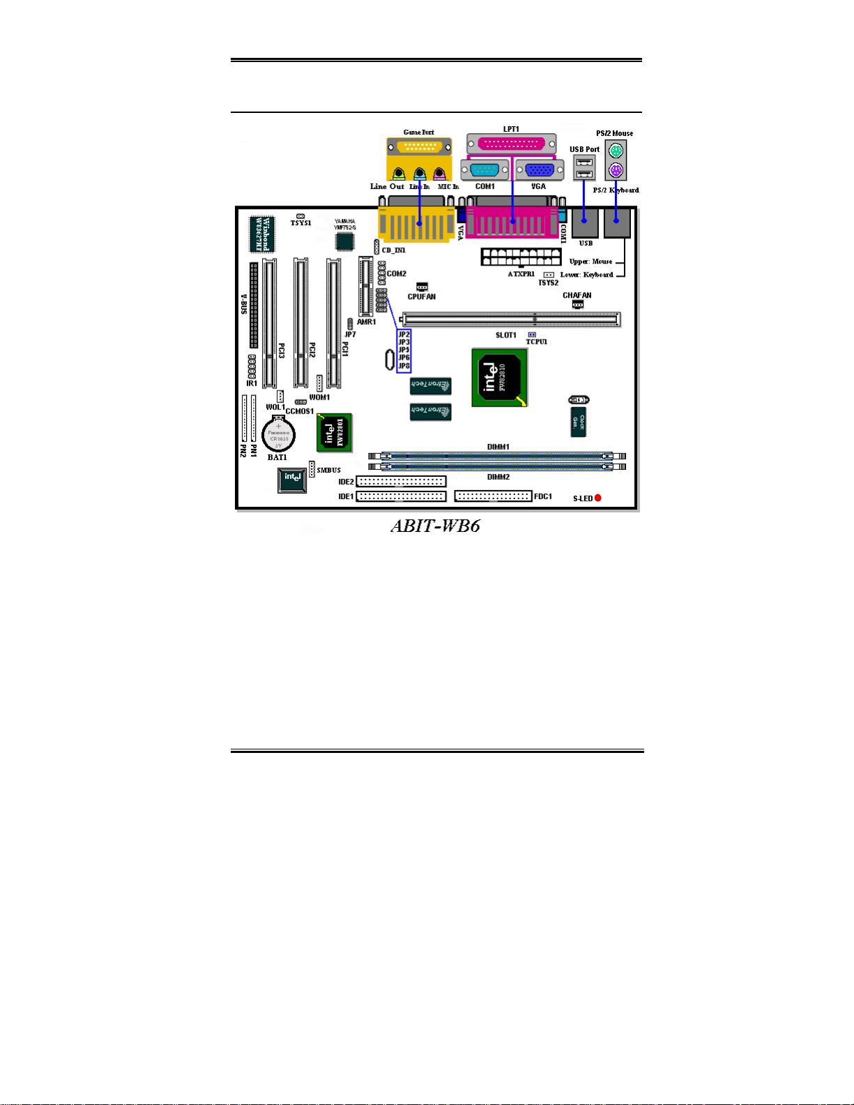
1-3. Layout Diagram
Figure 1-3. Motherboard component location
User's Manual
Page 12
1-8 Chapter1
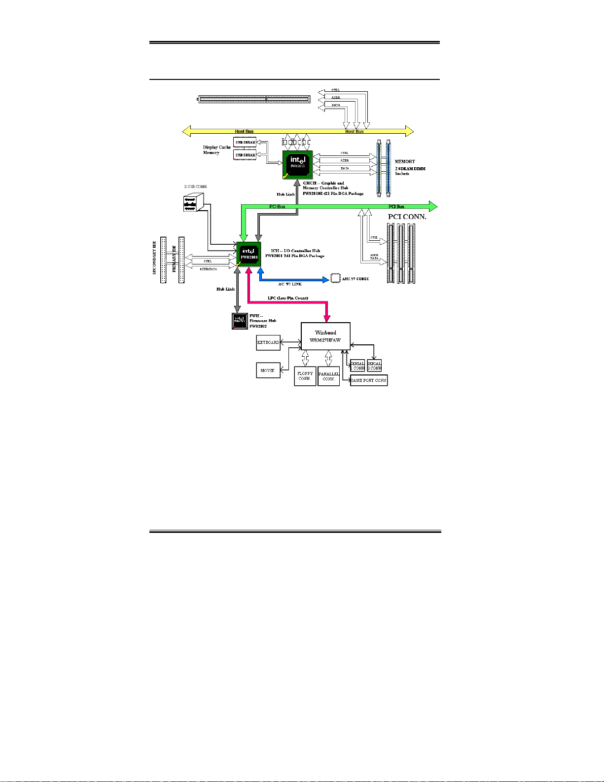
1-4. The System Block Diagram
WB6
Figure 1-4. System diagram of the WB6 mainboard
Page 13

Installing the Motherboard 2-1
Chapter 2. Installing the Motherboard
The WB6 motherboard not only provides all of the standard equipment for personal
computers, but also pr ovides great flexibilit y for meeting future upgrade dema nds. This
chapter will i ntroduce, step by step, all the standard equipment and will also pr esent, as
completely as possible, future upgrade capabilities. This motherboard is able to support all
the Pentium II /III and I ntel
specifications in Chapter 1.)
This chapter is organized acco r ding to the following featur es:
Celeron™ PPGA proce ssor s now on the market. (F or de tails, see
2-1 Ins talling the Motherboard to the Chassis
2-2 Installing the Pentium II/II and Celeron
2-3 Installing System Memory
2-4 Connectors, H eaders and Switches
%%%%
%%%%
%%%%%%%%
Before you install or un plug any connect ors or add-on card s, please remember t o turn the
ATX power supply switch off (fully turn the +5V standby power off), or take the power cord
off. Otherwise, you may cause the motherbo ar d co m ponents or add-o n cards to malfunc tio n
or be damaged.
Before Proceeding with the Installation
™
processor
%%%%
%%%%
%%%%%%%%
&&&&
User Friendly Instructions
Our objecti ve is to enab le th e novi ce comp uter u ser t o perfo rm th e ins ta llation by h ims elf.
W e have atte mp ted to wr ite t his doc ume nt in a ve ry cle ar, concise and descriptive manne r to
help overcome any ob st a c les you ma y fac e d u rin g inst a llati on . Pleas e read ou r ins t ruct ions
carefully and follow them step-by-step.
User's Manual
Page 14
2-2 Chapter2
2-1. Installing the Motherboard to the Chassis
Most computer chassis will have a base on which there will be many mounting holes that
allows the motherboard to be securely attached and at the same time, prevents short circuits.
There are two ways to attach the motherboard to the base of chassis:
" with studs
" or with spacers
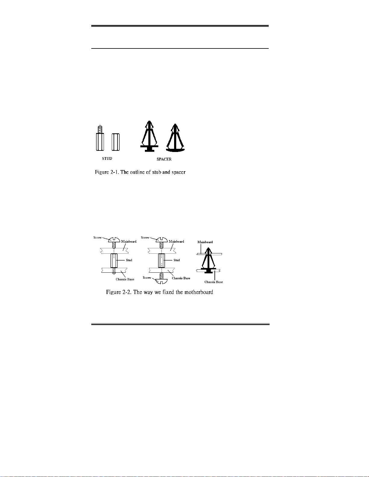
Please refe r to figure 2-1 tha t shows the studs and spacers, they may have s everal types, but
all look similar to the figures below:
In principle, the best way to attach the
motherboard is with studs, and only if
you are unable to d o this should you
attach th e board with spacer s. Take a
careful look at the motherboard and
you will see many mounting holes on
it. Line these holes up with the
mounting holes on the base. If the
holes line up, an d the re are sc rew hol es
this means you can attach the motherboard with studs. If the holes line up and there are only
slots, this means you can only attach the motherboard with spacers. Take the tip of the
spacers and insert them into the slots. After doing this to all the slots, you can slide the
motherboard into po sitio n alig ned w ith the slo ts. A fter the mother boar d has be en posit ioned,
check to make sure everything is OK before putting the casing back on.
Figure 2-2 shows you the way to affix the motherboard using studs or spacers:
WB6
Page 15

Installing the Motherboard 2-3
Note
If the motherboard has mounting holes, but they don’t line up with the holes on the base
and there are no slots to attach the spacers, don’t worry, you can still attach the spacers
to the mounting holes. Just cut the bottom portion of spacers (the spacer may be a little
hard to cut off, so be careful of your hands). In this way you can still attach the
motherboard to th e base without worrying about s hort circuits. Sometimes you may
need to use th e pl as ti c sp rin g s to i s olat e th e s cr ew fr om t h e mo th er b oa rd P CB su rf a ce,
because the cir c uit wire may be near by the hole. Be careful, do n’ t let the screw contact
any printed ci rcuit wire or p arts on the PCB th at are n ear the fi xing h ole, otherwis e it
may damage the board or cause board malfunctioning.
2-2. Installing the Pentium
II/III, Celeron
CPU
The installa ti on meth od for the C PU is p rint ed on th e pack age of th e reten ti on mec hani sm
that comes with the motherboard. You can refer to it while you install the CPU. This
motherboard also supports the Celeron
®
PPGA processor. If you want to install the Celeron
PPGA processor, you h ave to use an additiona l adapter th at allows you to use a Celeron
PPGA processor in a slot 1 board. For this ABIT makes the SlotKET adapter.
Note:
" Installing a heat sink and cooling fan is necessary for proper heat dissipation from
your CPU. Failin g to install th ese items may resu lt in overheat ing and damage of
your CPU.
" Please refer to your b oxed processor installa tion or other document ation attached
with your CPU for detailed installing instructions.
®
®
User's Manual
Page 16
2-4 Chapter2
2-3. Installing System Memory
This motherboard provides two 168-pin DIMM sites for memory expansion. The DIMM
sockets support 1Mx64 (8MB), 2Mx64 (16MB), 4Mx64 (32MB), 8Mx64 (64MB), 16Mx64
(128MB), and 32Mx64 (256 MB) or doub le si d ed DIMM m odules . Mi ni mum memory si ze
is 8MB and m axim um m em or y siz e is 256M B SD RA M ( 512 MB usi ng 1 28M b te chno l ogy ) .
There are two memory module sockets on the system board. (total four banks)
In order to create a memory array, certain rules must be followed. The following set of rules
allows for optimum configurations.
" The memory array is 64 or 72 bits wide. (Depending on with or without parity)
" Those modules can be populated in any order.
" Supports single and double density DIMMS.
Table 2-1. Valid Memory Configurations
Bank Memory Module Total Memory
Bank 0, 1
(DIMM1)
Bank 2, 3
(DIMM2)
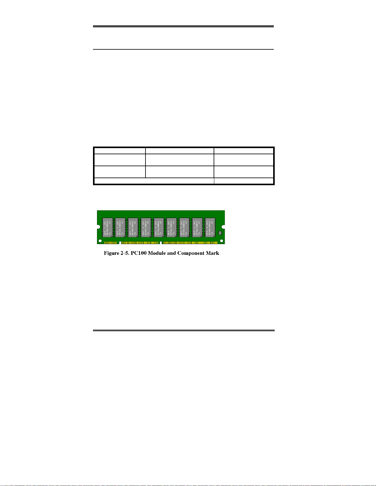
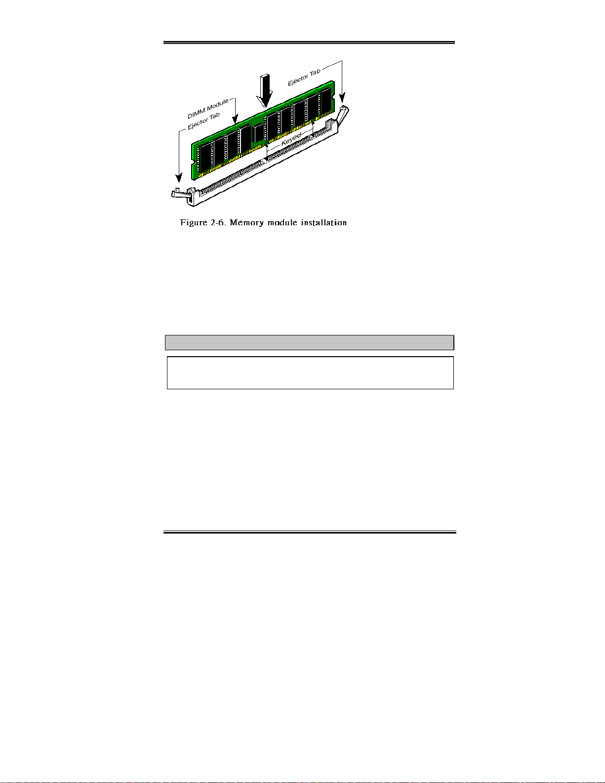
Generally, installing SDRAM modules to your motherboard is an easy thing to do. You can
refer to figure 2-5 to see what a 168-pin PC100 SDRAM module looks like.
8MB, 16MB,
32MB, 64MB, 128MB, 256MB
8MB, 16MB,
32MB, 64MB, 128MB, 256MB
Total System Memory 8 M B ~ 512MB
8MB ~ 256MB
8MB ~ 256MB
Unlike installing
SIMMs, DIMMs
may be "snapped"
directly into the
socket. Note:
Certain DIMM
sockets have minor
physical diff e r e nces.
If your module doesn't seem to fit, please do not force it into the socket as you may damaged
your memory module or DIMM socket.
The follow ing pr ocedur e w ill show y o u how to instal l a DI MM mod ule into a D I MM socke t.
Step 1.
Before you install the memory module, please place the computer power switch in
the off position and disconnect the AC power cord from your computer.
Step 2.
Remove the computer’s chassis cover.
WB6
Page 17
Installing the Motherboard 2-5
Step 3.
Before touching
any electronic components,
make sure you first touch an
unpainted, grounded metal
object to discharge any
static electricity stored on
your clothing or body.
Step 4.
Locate your
computer’s 168- pi n m em or y
expansion DIMM socket.
Step 5.
Insert the DIMM
module into the expansion
socket as shown in the
illustration. Note how the
module is keyed to the socket. You can refer to figure 2-6 for the details. This
insures the DIMM module will be plu gged int o the socke t in one way onl y. Firmly
press the DIMM module into the DIMM sock et, making certain the mod ule is
completely seated in the DIMM socket.
Step 6.
Once the DIMM modu le has been insta lled, the installa tion is complete an d the
computer’s cover can be replaced. Or you can continue to install other devices and
add-on cards that are mentioned in the following section.
Note
When you install a DIMM modu le fu lly i nt o the DIMM soc k et, th e ejec t tab sh ou ld b e
locked into the DIMM module very firmly and fit into it s indention on the bo th sides.
User's Manual
Page 18
2-6 Chapter2
2-4. Connectors, Headers and Switches
Inside the case of any computer several cables and plugs have to be connected. These cables
and plugs are usually connected one-by-one to connectors located on the motherboard. You
need to carefully pay attention to any connection orientation the cables may have and, if any,
notice the p os iti on of th e f ir st p in of t h e con nect or. In th e exp lana ti on s that follo w, we will
describe the significance of the first pin.
We will show you all connectors, headers and switches here, and tell you how to connect
them. Please pay attention and read the whole section for necessary information before
attempting to finish all of the hardware installat ion inside the com puter chassis.
Figure 2-7 s how s y o u all of the co nnec to rs and he ade rs that w e ’l l dis cuss in t he nex t se ctio n,
you can use this diagram to visually locate each connector and header we describe.
All connectors, headers and switches mentioned here, will depend on your system
configuration. Some features you may (or may not) have and need to connect or configure
depending on the peripheral . I f y our system doe s n't hav e such add-on car ds o r s witches you
can ignore some special feature connectors.
Figure 2-7. All Connectors and Headers for the WB6
First, Let’s see the headers that the WB6 uses, and what their functions are.
WB6
Page 19
Installing the Motherboard 2-7
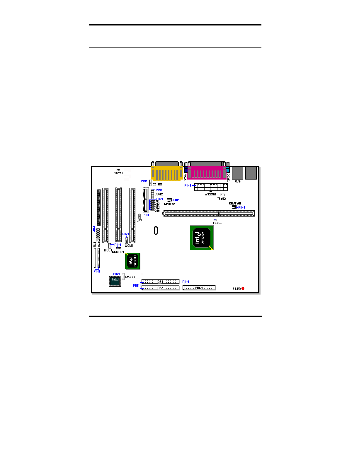
ATXPR1: ATX Power Input Connector
Caution
If the power supply co nnectors are not properly attached to the ATXPR1 connector, the
power supply or add-on cards may be damaged .
Attach the connector from the power supply
to the ATXPWR1 connector here.
Remember you have to push the connector
from the ATX power supply firmly to the
end with the ATXPWR1 connector, insuring
that you have a good connection.
Note: Watch the pin position and the
orientation
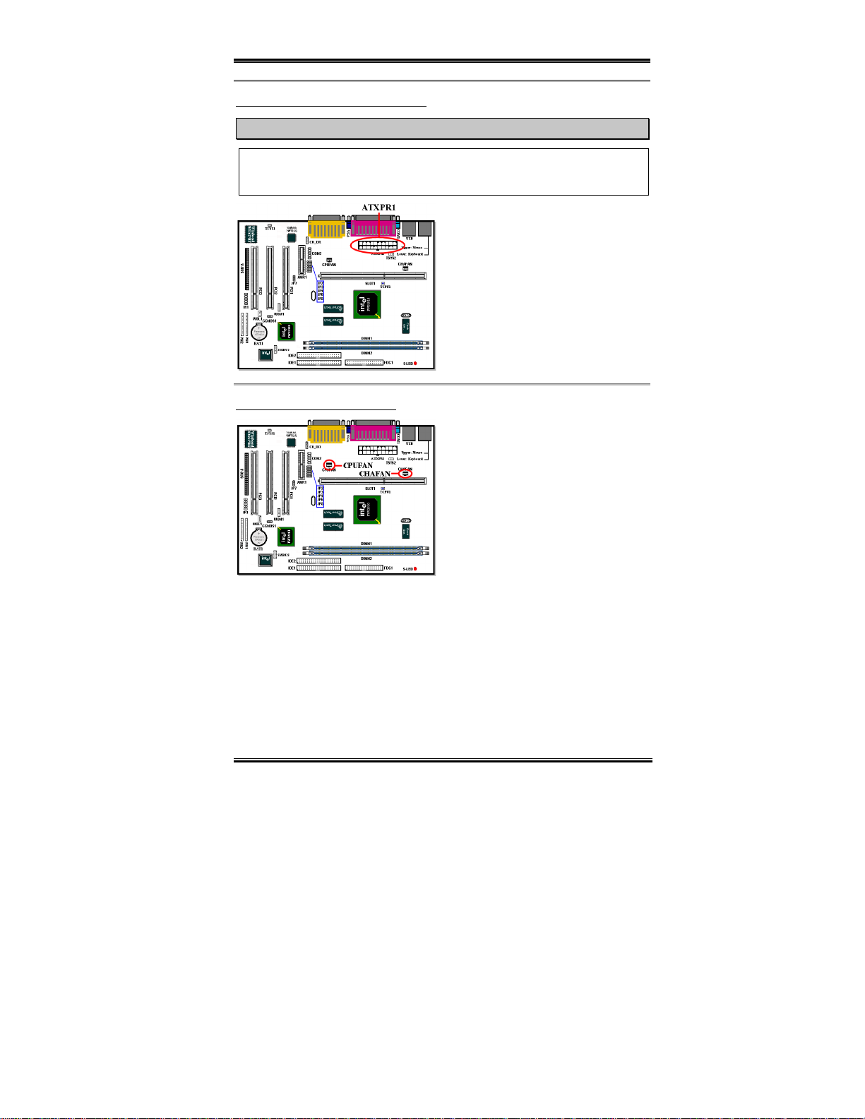
CPUFAN and CHAFAN Hea der s
Attach the connector from the individual
CPU fan to the he ade r n ame d CP UFAN, and
attach the con nector fr om the chas sis fan t o
CHAFAN header.
You must attach the CPU fan to the
processor, or your processor will work
abnormally or may be damaged by
overheating. Also, if you want the computer
case’s internal te mpe rat ure to be kept s te ady
and not too high, you had better connect the chassis fan.
Note: Watch the pin position and the orientation
User's Manual
Page 20
2-8 Chapter2
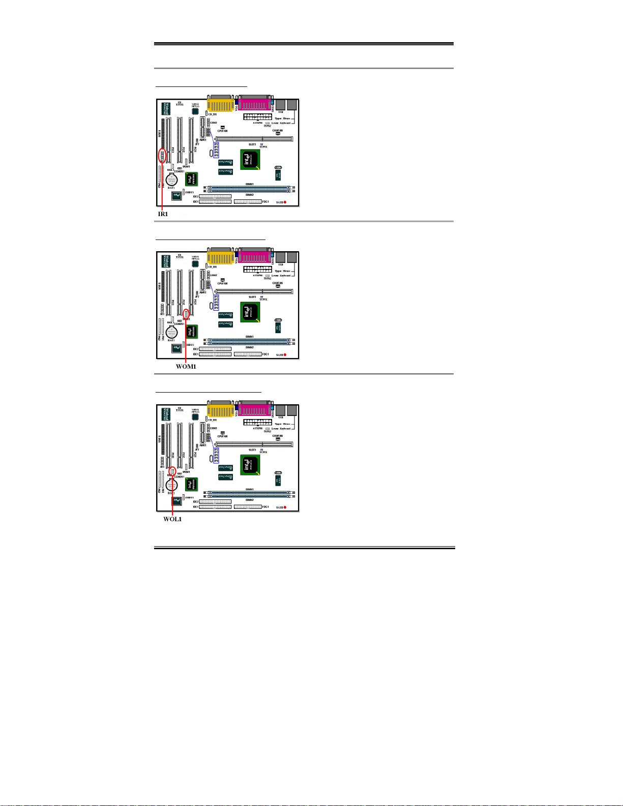
IR1: IR Header (Infrared)
There is a specific orientation for pins 1
through 10, attach the connector from the IR
KIT or IR device to the IR1 header. This
motherboard supports standard IR transfer
rates.
Note: Watch the pin position and the
orientation
WOM1: Wake On Ring Header
If you have an internal modem adapter that
supports this feature, then you c an connect
the speci fic cable f rom the inter nal mod em
adapter to th is header. This fea ture lets you
wake up your computer via remote control
through the modem.
Note: Watch the pin position and the
orientation
WOL1: Wake on LAN Header
WB6
If you have a Network adapter th at supp ort s
this feature, then you can connect the
specific ca ble from the network adapter to
this header. This feature lets you wake up
your computer via remote control through a
local area network. You may need a specific
utility to control the wake up event, like
using the Intel
®
LDCM® utility or other
similar utilit ies.
Note: Watch the pin position and the
orientation
Page 21
Installing the Motherboard 2-9
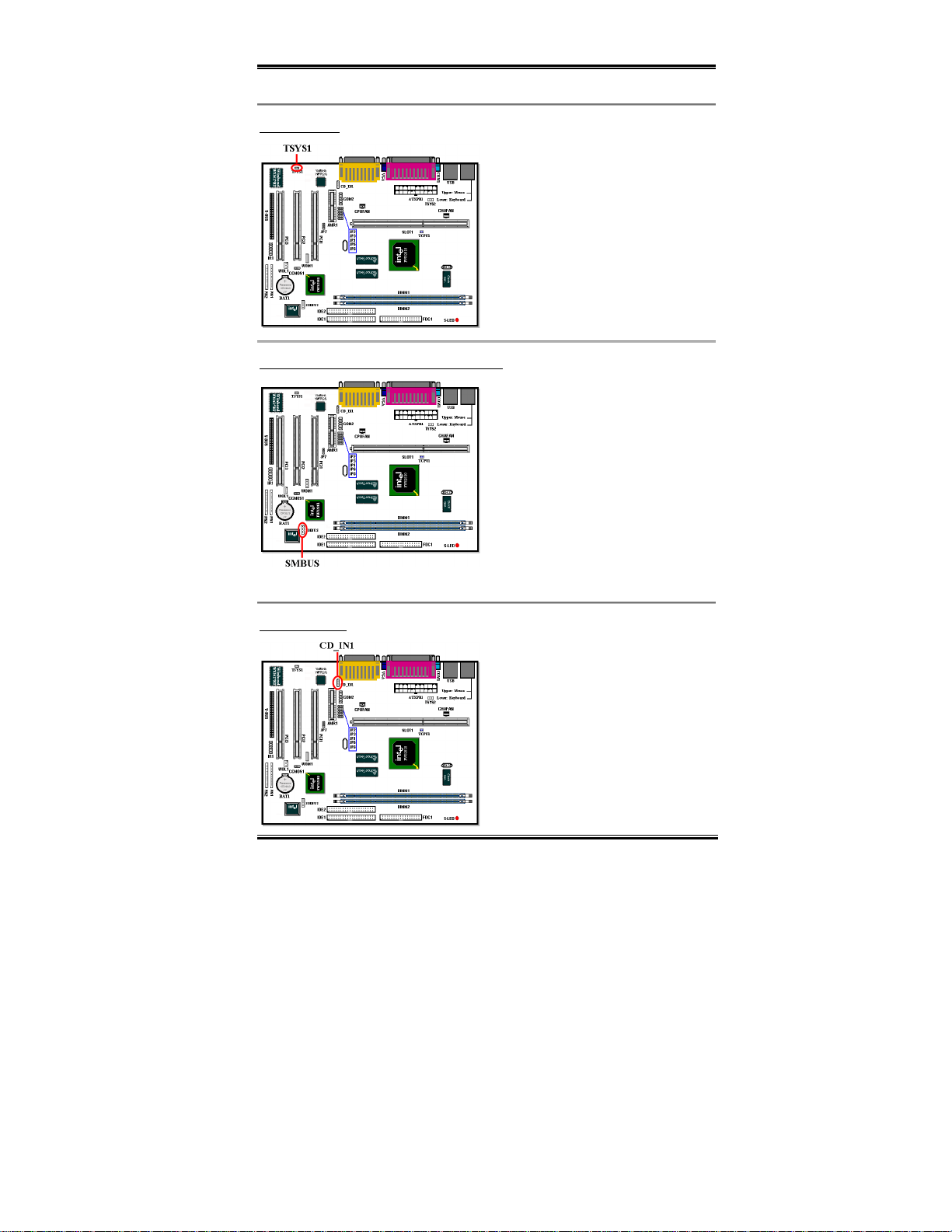
TSYS1 Header
The TSYS1 is for you to connect an
additional thermistor to detect the
temperature in the location of your choice.
You can buy the thermistor at an electronics
store, ask for a 10KΩ thermistor (NTC type )
which should be OK. Please don’t use too
long of a lead wire for the thermistor.
SMBUS: System Management Bus Connector
This connector is reserved for system
management bus (SMBus). The SMBus is a
specific implementation of an I
2
C bus. I2C is
a multi-master bus, which means that
multiple chips can be connected to the same
bus and each one can act as a master by
initiating a data transfer. If more than one
master simultaneously tries to control the
bus, an arbitration procedure decides which
master gets priority.
Note:
Watch the pin position and the orientation
CD_IN1 Header
This connector is used for the internal CDROM drive audio cable connection
User's Manual
Page 22
2-10 Chapter2
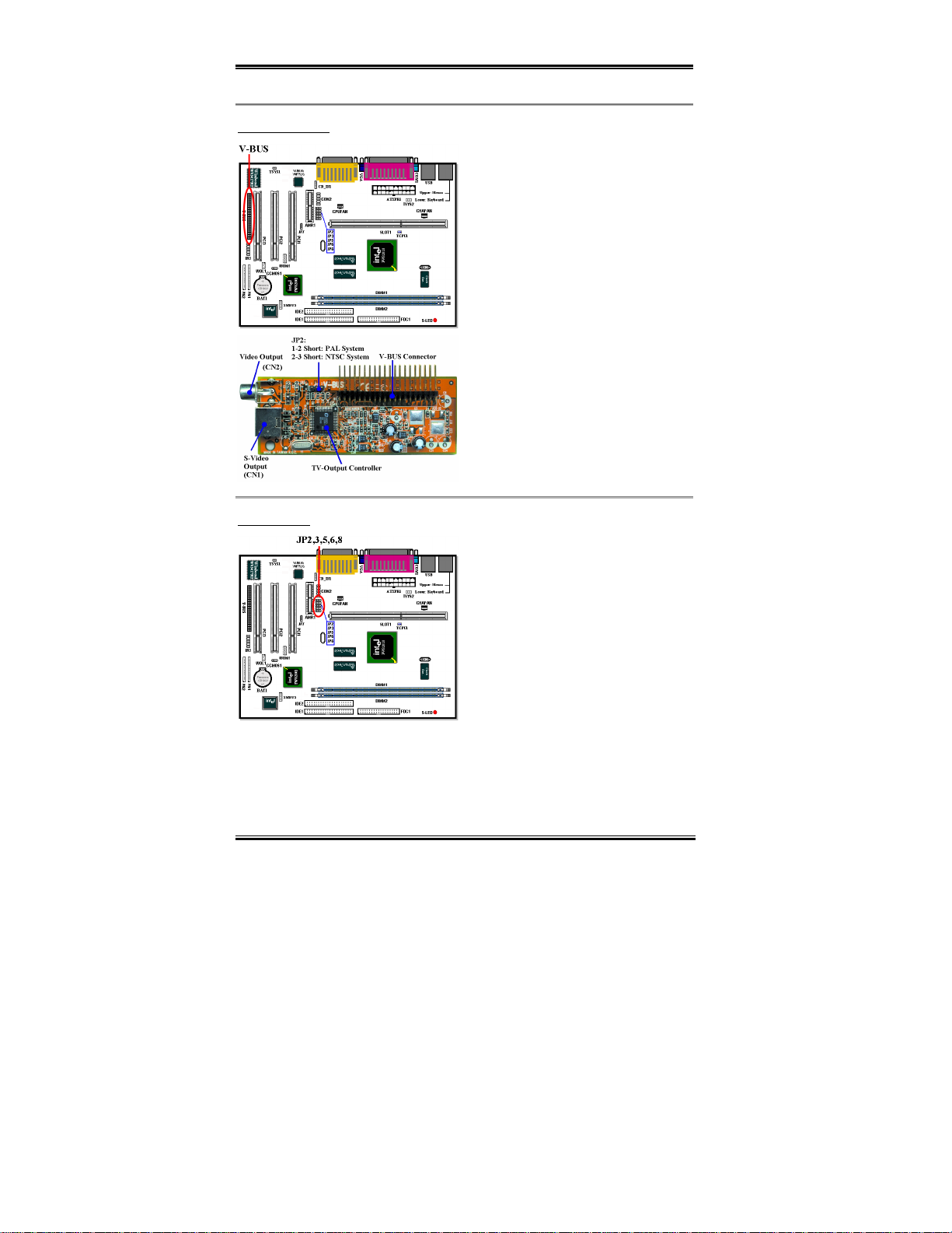
V-Bus Connector
V-BUS:
You can insta ll the V-B US a dapt er
to get video output capability. When you
install the V-BUS adapter, you can get two
video output capabilities. One is general
video output and the other is S-Video output
(Super-Video output). S-video output will
give you the be st dis pl ay qual ity on y o ur T V
monitor. Of course, your TV monitor must
have the S-Video input jack for a S-Video
cable connection. This card supports both
PAL and NTSC systems for various
purposes.
JP 2, 3, 5, 6, 8
WB6
These jump er settings are used in selectin g
use of the built-in audio chip, AU8810
optional
(
) or using the Intel
®
ICH i nte rnal
audio controll er.
JP2, 3, 5, 6, 8 pin 1 and pin 2 shorted:
This setting will choose the use of the ICH
internal audio controller. (Default)
JP2, 3, 5, 6, 8 pin 2 and pin 3 shorted:
This setting will choose the use of the
AU8810 audio chip.
Page 23
Installing the Motherboard 2-11
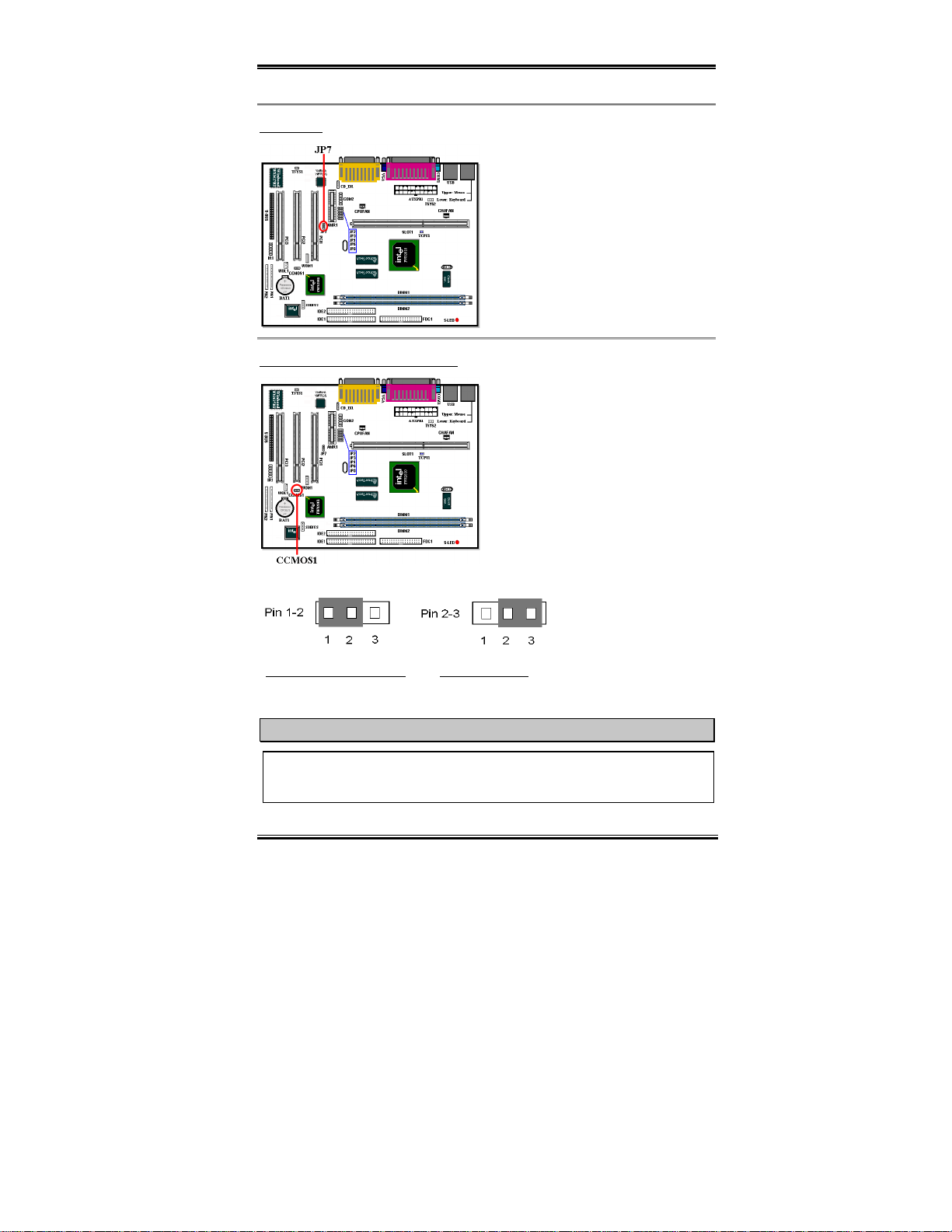
JP7 Header
This Jumper is u sed in selecting u se of the
built-in audio chip, YMF752 or using the
AMR audio controller.
CCMOS1: CMOS Discharge Jumper
Jumper 1-2 shorted:
CODEC (use YMF752) (Default)
Jumper 2-3 shorted:
CODEC (use AMR)
Jumper CCMOS1 discharges the CMOS
memory. When you install the motherboard,
make sure this jumper is set for normal
operation (pin 1 and 2 short ed). See figure
2-8.
Disable AMR
Disable onboard
Normal Operation (Default) Discharge CMOS
Figure 2-8. CCMOS1 jumper setting
Note
Before you clear the CMOS, you have to first turn off the p ower (including the +5 V
standby power), otherwise, your system may work abnormally or malfunction.
User's Manual
Page 24
2-12 Chapter2
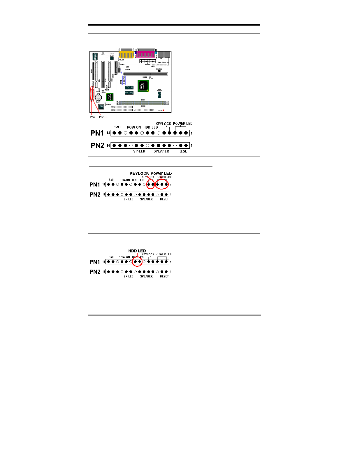
PN1 and PN2 Headers
PN1 and PN2 are f or sw itches and i ndicato rs
for the chassis’s front panel, there are
several functi ons that come from th ese two
headers. You have to watch the pin position
and the orientation, or you may cause
system malfunction s. Figure 2 -9 shows you
the functions of PN1 and PN2.
Figure 2-9. The Explanatory
Diagram of PN1 an d PN2
PN1 (Pin 1-2-3- 4- 5) : Po w er LED and Keylock Switch H eaders
There is a specific orientation for pins 1
through 3. Insert the three-threaded power
LED cable to pins 1~3, and t he tw o- threade d
keylock cable in to pins 4 and 5. Check t o
make sure the correct pins go to the correct
connectors on the motherboard. If you install them with the wrong direction, the power LED
light will not illuminate correctly.
Note: Watch the power LED pin position and ori entation.
PN1 (Pin 7-8): HDD LED Header
Attach the cable f rom th e cas e’s fron t pan el
HDD LED to this header. If you install it in
the wrong direction , the LED light will not
illuminate correctly.
Note: W at c h t he HDD LED pi n position and
the orientation.
WB6
Page 25

Installing the Motherboard 2-13
PN1 (Pin 10-11): Power on Switch Header
Attach the cab le from t he ca se’s fro nt panel
power switch to this header.
PN1 (Pin 13-14): Hardware Suspend Switch (SMI Switch) Header
Attach the cab le from t he ca se’s fro nt panel
suspend switch (if there is one) to this
header. Use this switch to enable/disable the
power management function by hardware.
Note: If you enable the ACPI function in
the BIOS setup, this function will not work.
PN2 (Pin 1-2): Hardware Reset Switch Header
Attach the cab le from t he ca se’s fro nt panel
Reset switch to this header. Press and hold
the reset button for at least one second to
reset the system.
PN2 (Pin 4-5-6-7): Speaker Header
Attach the c ab le fro m t h e syst em sp ea k er t o
this header.
PN2 (Pin 9-10): Suspend LED Header
Insert the two-t hreaded suspend LED c able
into pin 9 and pin 10. If you insta ll it in the
wrong direction, the LED light will not
illuminate c orrectly.
Note: Watch the Suspend LED pin
position and the orientation. For pin count-name list for PN1 and PN2, please refer to
table 2-3.
User's Manual
Page 26
2-14 Chapter2
Table 2-3. PN1 and PN2 pin count name list
PIN Name Significance of signal PIN Name Significance of signal
PIN 1 VCC (+5VDC) PIN 1 Ground
PIN 2 No connecti on PIN 2 Reset input
PIN 3 Power LED (-) PIN 3 No connection
PIN 4 Keyboard inhibit Signal PIN 4 VCC (+5VDC)
PIN 5 Ground PIN 5 Ground
PN1
PIN6 No connection PIN6 Ground
PIN 7 VCC (+5VDC) PIN 7 Speaker Signal
PIN 8 HDD LED (-) PIN 8 No connection
PIN 9 No connection PIN 9 VCC (+5VDC)
PIN 10 5VSB PIN 10 Suspend LED (-)
PIN 11 Power On/Off PIN 11 No connection
PIN 12 No connection PIN 12 No connection
PIN 13 Ground PIN 13 No connection
PIN 14 Suspend signal
Let’s now look at the I/O connectors that the WB6 uses, and what their functions are.
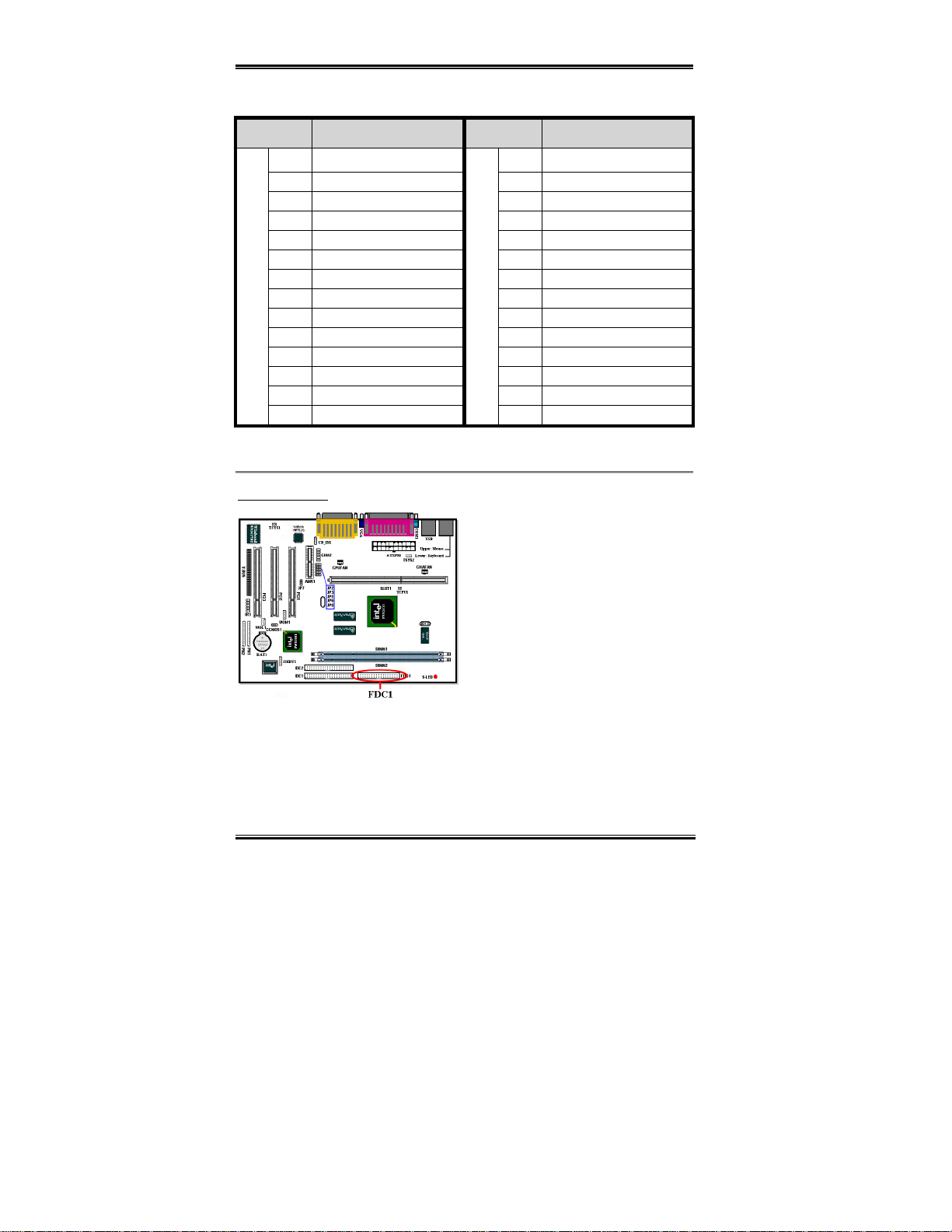
FDC1 Connector
PN2
PIN 14 No connection
This 34-pin connector is c alled the “floppy
disk drive connector”. You can connect a
360K, 5.25”, 1.2M, 5.25”, 720K, 3.5’’,
1.44M, 3.5” or 2.88M, 3.5” floppy disk
drive.
A floppy disk drive ribbon cable has 34
wires and two connec tors to provid e for th e
connection of two floppy disk drives. After
connecting the single end to the FDC1,
connect the two connectors on the other end
to the floppy disk drives. In general, people only install one floppy disk drive on their
computer system.
WB6
Page 27
Installing the Motherboard 2-15
Note
A red mark on a wire typically designates the location of pin 1. You need to align the
wire pin 1 to the FDC1 connec tor pin 1, then inser t the wire c onnect or int o the FDC1
connector.
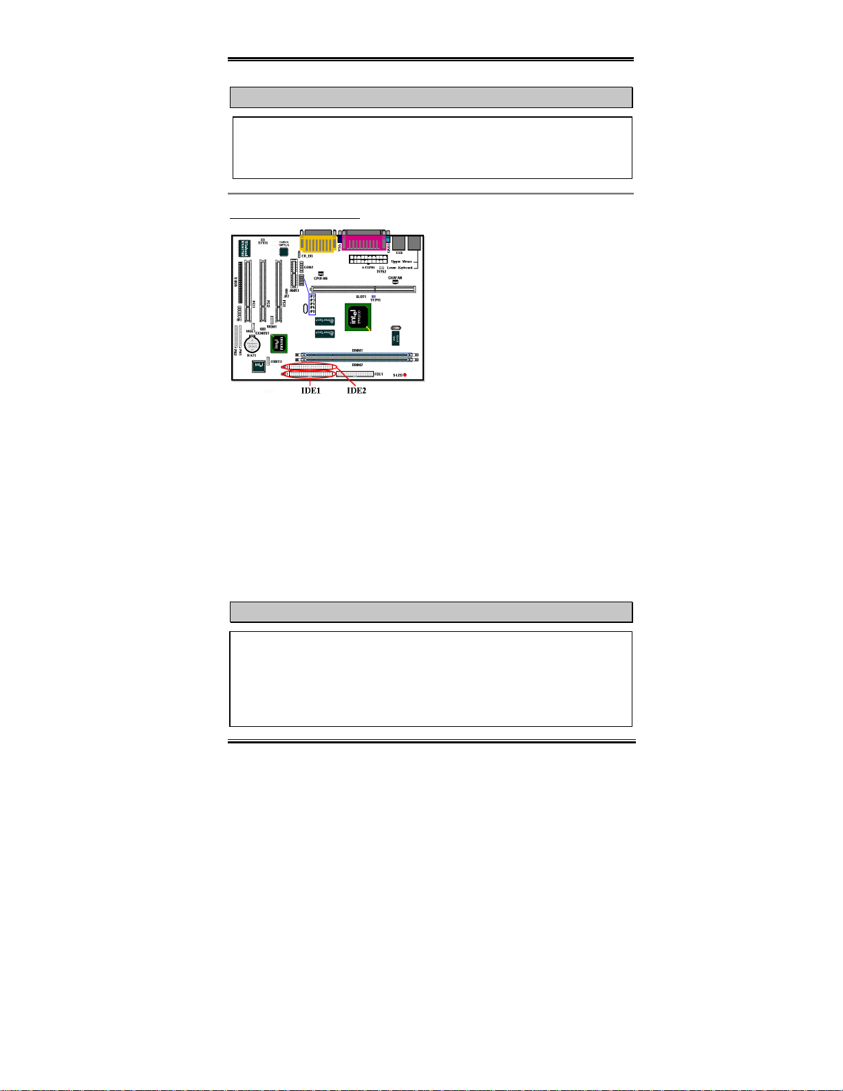
IDE1 and IDE2 Connectors
An IDE hard disk drive ribbon cable has 40
wires and two connectors to provide a
connection for two IDE hard disk drives.
After connecting the single end to the IDE1
(or IDE2), connect the two connectors on
the other end to the IDE hard disk drives (or
CD-ROM drive, LS-120, etc.).
Note: before you install a har d disk, there are s ome things you n eed to be aware of:
♦ “Primary” refers to the first connector on the motherboard, that is, the IDE1 connector on
the motherbo ard.
♦ “Secondary” refers to the second connector on the motherboard, that is, the IDE2
connector on t he motherboard.
♦ Two hard disks can be connected to each connector:
The first HDD is referred to as the “Master”, The second HDD is referred to as the
“Slave”.
♦ For performance issues, we strongly suggest you don’t install a CD-ROM drive on the
same IDE channel as a har d disk. O therw ise, the sys tem perf orma nce on th is channe l may
drop. (How much drops depends on your CD-ROM drive performance)
Note
" The Master or Slave status of the hard disk drive is set on the hard disk itself. Please
refer to the hard disk drive user’s manual.
" A red mark o n a wire typically de s ig nates the locatio n o f pin 1. You need to alig n the
wire pin 1 to the IDE1 (or IDE2) con necto r pi n 1, the n insert the wire conne cto r into
the IDC1 (or IDE2) connector.
User's Manual
Page 28
2-16 Chapter2
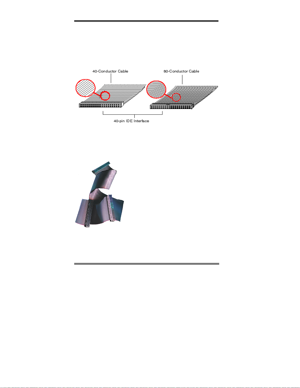
The WB6 supports the Ultra ATA/66 (Also known as Ultra DMA/66) specification. It
enhances existing Ultra ATA/33 technology by increasing both performance and data
integrity. This new high-spee d i nte r f ace doubles the U l tr a ATA/33 burst data transf e r r a te to
66.6 Mbytes/sec. The result is maximum disc performance using the current PCI local bus
environment. Figure 2-10 shows you the different between the Ultra ATA/33 and Ultra
ATA/66 Conductor Cable.
Figure 2-10. The difference between Ultra ATA/33 and Ultra ATA/66 Conductor Cables
Figure 2-11 shows you a ph oto of an Ultra ATA/6 6 Conductor Cable. An Ultra ATA/66 capable cable i s a 40-pin, 80-conductor cab le with a black connec tor on one end, a blue
connector on th e other en d and a gra y connect or in th e middle. In addit ion, lin e 34 on th e
cable should be notched or cut (this may be difficult to see).
Ultra ATA/66 is backwards compatible with all Ultra
ATA/33 systems, but it will be limited in its transfer mode
to the Ultr a ATA /33 (U ltra D MA Mo de 2 - 33 Mbyte s/se c)
or PIO Mode 4 (16.6 Mbytes/sec). Ultra ATA/66 hard
drives are 10 0 percent backward com patible with both
Ultra ATA/33 and DMA an d with exis ting ATA (IDE)
hard drives, CD-ROM drives, and host systems. The
Ultra ATA/66 pro tocol and commands are designed to be
compatible with existing ATA (IDE) devices and sy stems.
Although a new 40-pin, 80-conductor cable is required
for Ultra ATA/66, the chip set pin connector remains the
Figure 2-11. Photo of an
Ultra ATA/66 Conductor
same at 40. Hard drives that support Ultra ATA/66 also
support Ultra ATA/33 and legacy ATA (IDE)
specifications.
There are four requirements for attaining Ultra ATA/66:
*The drive must support Ultra ATA/66.
WB6
Page 29
Installing the Motherboard 2-17
*The motherboard and system BIOS (or an add-in controller) must support Ultra ATA/66.
*The operating system must support Direct Memory Acc ess (DMA); Mi crosoft Windows
98 and Windows 95b (OSR2) support DMA.
*The cable mus t b e 80-cond uct or; t he leng th sh ould not exc eed 1 8 in ches. If all t he ab ove
requirements are met, you can enjoy the Ultra ATA/66 features of your computer system.
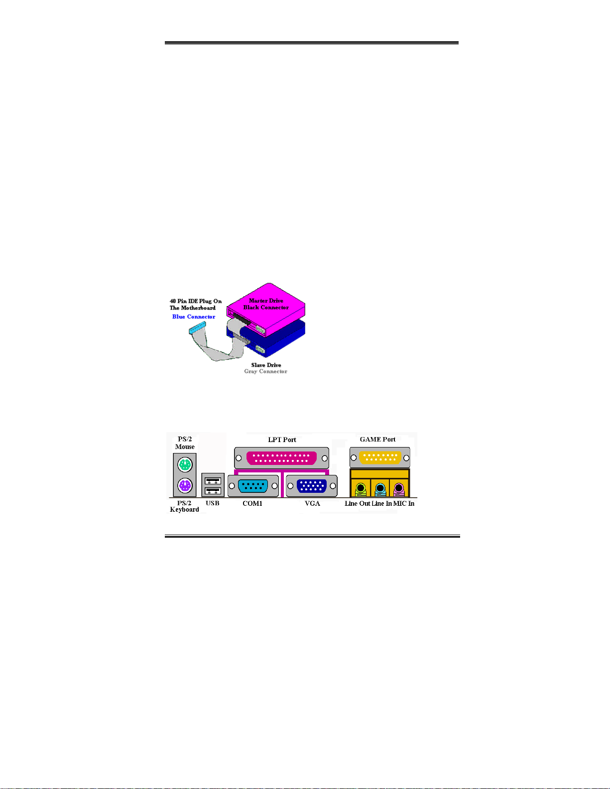
How to install the Ultra ATA/66 Cable Assembly:
BLUE
! The
work.
! Each connecto r o n the Ul tra ATA/66 cable assembly has a sm al l po lar iz atio n ta b cen tral l y
located on the body of the plastic. This fits into the matching slot on the mating plugs on
the motherboa r d and the drives, thus assuring positive mating (pin #1 to pin #1)
! The red line on t he cabl e sho ul d be al igned w it h pi n #1. O n the driv es th is wi ll r esul t in t he
red line facing the power connector. Attach the BLUE connector to the appropriate 40 pin
IDE plug on the motherboard.
! Attach the BLACK connector to the mating plug on the master hard drive. Attach the
GREY connect or to the mating plug on the slave drive (seconda r y h ard drive, CD-RO M,
or tape drive). Please refer figure 2-12.
Figure 2-13 shows the WB6 back panel connectors, these connectors are fo r connection s to
outside devices to the motherboard. We will describe which devices will attach to these
connectors below.
connector
MUST
be plugged into the motherboard or your system will not
Figure 2-12. How to connect an ATA/66
Cable to the Motherboard
Figure 2-13. WB6 back panel connectors
User's Manual
Page 30

2-18 Chapter2
KBM Lower: PS/2 Keyboard Connector
Attach a PS/2 keyboard connector to this 6-
pin Din-connector. If you use an AT
keyboard, you can go to a computer s tore t o
purchase an AT to ATX converter adapter,
then you can connect your AT keyboard to this connector. We suggest you use a PS/2
keyboard for best compatibility.
KBM Upper: PS/2 Mouse Connector
Attach a PS/2 mouse to this 6-pin Din-
connector.
USB Port Connectors
This motherboard provides two USB ports.
Attach the USB connector from the
individual device to these connectors.
You can attach USB devices such as a,
scanner, digital speakers, monitor, mouse, keyboard, hub, digital camera, joystick etc. to one
of each USB connector. Y ou must make sure your operating system supports this feature and
you may need to in stall an additiona l driver for i ndividua l devices . In Please r efer to your
device user’s manual for detailed information.
Serial Port COM1 & COM2 Port Connector
This motherboard pro vide s tw o COM ports,
you can connect an external modem, mouse
or other devices that support this
communication protocol to these connectors.
The WB6 has one built-in COM1 port connector on the motherboard, the other COM2 port
will be atta ched to the p late wit h th e c able in your m oth erboa rd pack age. You can connect
and fix it on the comp ute r chas sis’s back panel.
You can decide which external devices you want to connect to COM1 and COM2. Each
COM port can only have one device connected at a time.
WB6
Page 31

Installing the Motherboard 2-19
VGA Port Connector
This DIN 15 pin Female connector is for
VGA signal output to th e monitor. You can
connect the plug from the monitor to this
connector. If you don't move your system
often, we suggest you to fasten the two scre ws from the plug with th is connector. It will
assure your display quality.
Parallel Port Connector
This parallel port is also called an “LPT”
port, because it usually connects to the
printer. You can connect other devic es that
support this c ommunic ation p rotoc ol, like a
EPP/ECP scanner, etc.
Line Out, Line In and Mic In Connector
Line Out connector:
external stere o speaker s ignal input p lug to
this connector, or you can connect the plug
from here to the stereo audio equipment
AUX signal input socket. Remember, the motherboard does not have a built in amplifier to
drive the speake r , y ou have to use a spe ake r that ha s a built in ampl ifie r . Other wise , you may
not be able to hear any sound or only a small volume of sound from the speaker.
Line In Connector:
audio sources, like a CD walkman, video camcorder, VHS recorder audio output signal plug
to this connector. Your audio software can control the input level fo r the line-in si gn al.
Mic In Connector:
not connect other audio (or signal) sources to this connector.
GAME Port Connector
user's manual for further detailed information.
You can connect the TV adapter audio output signal, or external
You can connect the plug f r om the microphone to this connector. Do
You can connect your jo ystick, game pad, or
other simulation hardware device DIN 15-
pin plugs to this connector. Please refer to
the further connection notes of the device’s
You can connect an
User's Manual
Page 32

2-20 Chapter2
WB6
Page 33

BIOS Setup 3-1
Chapter 3. Introduction of The BIOS
The BIOS is a program located on a FWH (Firmware Hub) chip on the motherboard. This
program will not be lost when you turn the computer off. This program is also referred to as
the “boot” program. It is the only channel for the hardware circuit to communicate with the
operating system. Its main function is to manage the setup of the motherboard and interface
cards parameter s, i ncl uding sim ple param ete rs su ch as tim e, date , har d dis k dr iv e, as w e ll as
more complex paramet ers su ch a s hard ware synch ron i zati on, devi c e opera ti n g mode,
SOFT MENU™ II
will operate at its best, on ly if all th ese pa ramet ers are c orrect ly and optimally c onfi gured
through the BIOS.
Do not change the parameters inside the BIOS unless you fully understand
''''
their meanings and consequences.
The parameters inside the BIOS are used to setup the hardware synchronization or a
device’s operating mode. If the parameters are not correct, they will produce errors, the
computer will crash, and so metime s yo u will even not be able to boot the compu ter af ter
it has crashed. We recommend that you do not change the parameters inside the BIOS
unless you are very familiar with them. If you are not able to boot your computer
anymore, please refer to t he “CMOS Discharge Jumper” in Section 2-4, Cha pter 2.
features and setup of CPU speed. The computer will operate normally, or
CPU
When you start the computer, it is controlled by the BIOS program. The BIOS first operates
an auto-diagnostic test called POST (Power On Self Test) for all the necessary hardware, it
then configures the parameters of the hardware synchronization, and detects all the
hardware. Only when thes e tasks a re complet ed does i t give up cont rol of the c omputer t o
the program of the next level, which is the operating system (OS). Since the BIOS is the only
channel for hardware and software to communicate, it is the key factor for system stability,
and in insuring that your system performs at its best. After the BIOS has achieved the
auto-diagnostic and auto-detection operations, it will display the following message :
PRESS DEL TO ENTER SETUP
The message will be displayed for three to five seconds, if you press the
access the BIOS Setup menu. At that moment, the BIOS will display the following screen:
Del
key, you will
User's Manual
Page 34

3-2 Chapter3
Note
( T o improve stabili ty and functions , BIOSes ar e constantly impro v ing , therefore; the
BIOS screens i n this chapter m ay not fully match your current BIOS screen.
) All default setting is use the Load Optimized Defaults settings. If you use the Load
Fail-Safe Defaults, some items default values will be changed.
Figure 3-1. CMOS Setup Utility Main Screen Shot
This motherboard uses a totally different operating interface so the Award BIOS screens are
different than in other versions. It provides more functions with increased user friendliness.
In the BIOS Setup main men u in Figure 3- 1, you can see severa l option s. We will explain
these option s st ep b y step in th e f ollowing p ages of t hi s chap ter, but let u s firs t see a short
description of the function keys you may use here:
" Press !
in the main m enu .
" Press the
you want to select, and press Enter.
" Press
the BIOS Setup menu.
" Press
" Press F1 to display the Genera l Help screen.
In addition to the
function by pressing the F1 key in any menu in the BIOS.
WB6
$ (up, down, and right) to choose the option you want to confirm or to modify
!!!""""####$$$
Enter
key to select the item you wan t. Si mply move th e highli ght to the field
F10
when you have completed setting up the BIOS parameters to save them and exit
Esc
to Exit the BIOS Setup.
Item Help
window, more information can be provided for the alternate
Page 35

BIOS Setup 3-3
" Press F5 to reset current screen settings to their Setup Default values.
" Press F6 to return to the Fail-Safe Default setting i.e. if you use the wrong set tings
causing a syste m bo ot f a ilur e, use this f unct ion ke y to qu ickl y r etur n to t he s y ste m de faul t
settings.
" Press F7 to quickly set the system to the Optimized Defaults setting.
In some setup menu screens, you can see the
scroll bar on the ri ght side of the window.
You can use the * and + key s o r the up and
down arrow keys to scroll the screen to view
more help information or functions to select.
You may see the right cursor symb ol app ea r
on the left side of some items, indicating that
additional information or options can be
select in a Sub-Menu for this item.
Note
The item heading in the square outlet represents the default setting for that field
Computer Knowledge: CMOS Data
Maybe you have heard of someone losing CMOS DATA. What is the CMOS? Is it
important? CMOS is the memory in which the BIOS parameters that you have
configured are stored. This memory is passive, you can both read its data, and store data
in it. But this memory has to be powered by a battery in order to avoid data loss when
the computer is turned off. If the CMOS battery dies, you will loose all CMOS data. We
therefore recommend that you write down all the parameters of your hardware, or you
put a label with these parameters on your hard disk.
User's Manual
Page 36

3-4 Chapter3
3-1. CPU Soft Menu™ II
™
The CPU can be setup through a programmable switch (
CPU SOFT MENU
replaces the tra dit io nal m an ual har dw are co nfig urat ion . This fe ature all ow s the use r to m or e
easily compl ete the inst alla tion proce dure s. You can install the CP U w ithou t conf igur ing any
jumpers or switches. The CPU must be setup according its specifications.
Figure 3-2. CPU Soft Menu II Screen Shot
II
), that
CPU Name Is:
➤ Intel Pentium III
➤ Intel Pentium II
➤ Inte l Celeron
MMX
MMX
MMX
CPU Operating Speed:
This option sets the CPU speed.
In this field , t he CP U sp eed is ind ic ated lik e th i s: C PU sp eed = E xt ern a l clock * Mult ip li er
factor, select the CPU speed accordin g the type and the speed of your CPU.
For Intel Pentium® II/II and Celeron™ PPGA MMX processors, you can choose the
following settings:
➤233 (66) !
default
!
!!
➤266 (66) ➤300 (66) ➤300 (100)
➤333 (100) ➤350 (100) ➤366 (66) ➤400 (66)
WB6
Page 37

BIOS Setup 3-5
➤400 (100) ➤433 (66) ➤450 (100) ➤466 (66)
➤500 (66) ➤500 (100) ➤533 (66) ➤533 (133)
➤550 (100) ➤600 (100) ➤600 (133) ➤650 (100)
➤667 (133) ➤700 (100) ➤733 (133) ➤800 (100)
➤800 (133) ➤User Define
User defined external clock and multiplier factor:
User Defined:
➤➤➤➤
When you choose the User Define, you will bw ab le to set the followi ng five items.
%%%%
%%%%
%%%%%%%%
The wrong settings of the multiplier and external clock in certain circumstances may
cause CPU damage. Setting the worki ng frequency higher than the PCI chip set or
processor specs, may cause abnormal memory module functioning, system hangs,
hard disk drive data lose, abnormal functioning of the VGA card, or abnormal
functioning with other add-on cards. Using non-specification settings for your CPU is
not the inte ntion o f th is ex planat ion. Thes e s hould be use d fo r eng inee ring te sting, no t
for normal applications.
If you use non-specification settings for normal operation, your system may not be
stable, and ma y effect syst em reli ab ili ty. Also, we do not gua rantee th e st abili ty and
compatibi lity for settings that are not within speci fication, and an y damage of any
elements on the motherboard or peripherals, is not our responsibilit y.
Ext. Clock (PCI):
✏✏✏✏
➤66MHz (1/2) !
➤68MHz (1/2) ➤70MHz (1/2) ➤83MHz (1/2)
➤107MHz (1/3) ➤112MHz (1/3) ➤124MHz (1/3)
➤133MHz (1/3) ➤138MHz (1/4) ➤138MHz (1/3)
➤140MHz (1/4) ➤143MHz (1/4) ➤150MHz (1/3)
If you want to chan ge your CPU, be sure to first cut off the AC power of your
computer, don’t attempt while computer is in “Shutdown” only mode. Furthermore,
you also need to use the CC MOS1 jumper to clear the CMOS after you change your
CPU (refer to section 2-4).
default
!
!!
Warning
➤100MHz(1/3) ➤133MHz (1 /4)
Important Notice
%%%%
%%%%
%%%%%%%%
User's Manual
Page 38

3-6 Chapter3
ICS 9248-87 Frequency Selections
CPU (Ext. Clock) SDRAM PCI
66.8 100.2 33.4
100.30 100.3 33.4
133.60 133.6 44.53
68.33 102.5 34.17
70.0 105.0 35.0
83.3 83.3 27.74
107.0 107.0 35.67
112.0 112.0 37.33
124.0 124.0 41.33
133.60 100.2 33.4
137.33 103.0 34.34
138.0 138.0 46.0
140.0 105.0 35.0
155.0 155.0 51.67
143.96 108.0 36.0
150.0 150.0 50.0
Multiplier Factor:
✏✏✏✏
You can choose t he following mult iplier factors:
➤ x2 ➤ x2.5 ➤ x3 ➤ x3.5 ➤ x4 ➤ x4.5 ➤ x5 ➤ x5.5 ➤ x6
➤ x6.5 ➤ x7 ➤ x7.5 ➤ x8
The default setting is x4.5.
L2 Cache Latency:
✏✏✏✏
Sixteen sett ing ar e availab le, Defa ult, and 1 to 15. This it em can let you adju st th e
processor L2 cache speed, the larger the valu e, the faster the L2 cache will run. You
have to be awar e that if y ou set t he L 2 cache spee d too fast, it w ill cause the L 2 cache
to fail. If the L2 cache fails it will cease to run until you reset the value, but the
processor and L1 cache will still function, just not as well. To make sure your L2
cache functions properly please choose an appropriate setting. The default setting is
Default.
Speed Error Hold:
✏✏✏✏
The default setting is Enabled. If you change the setting to Disabled, when the CPU
speed setting is wrong, the system will not hold.
Normally, we do not recommend that you use the “U ser Define” option to se tup CPU speed
and multipli er fa c tor s Thi s opt i on is f or set up of f utu r e CPUs whos e sp ec i fi cati on s are st i ll
unknown. The specifications of all present CPUs are included in the default settings. Unless
you are very fami liar wit h a ll CPU param eters, it is ver y eas y to ma ke mi sta kes when you
define the external clock and the multiplier factor by yourself.
WB6
Page 39

BIOS Setup 3-7
Solution in case of booting problem due to invalid clock setup:
Normally, if the CPU clock s etu p is w ro ng, y o u wil l not be a ble to bo ot. In this case, turn the
system off then on again . The CPU will a utom aticall y use its standard parameters to boot.
You can then enter the BIOS Setup again and set up the CPU clock. If you can’t enter the
BIOS setup, you must try turning the system on a few times (3~4 times) or press
“INSERT“ key when turning on and the system will automatically use its standard
parameters to boot. You can then enter BIOS SETUP again and set up the new parameters.
When you change your CPU:
This motherb oard has been design ed in such a way th at you ca n turn the syst em on aft er
having inserted a CPU in the socket without having to configure any jumpers or DIP
switches. But if you change your CP U , nor m al ly you just have to turn off the power suppl y,
change the CPU and then, set up the CPU parameters through
SOFT MENU
™
II. Howeve r ,
if the new CPU is slower than the old one (and is same brand and type), we offer you two
methods to successfully complete the CPU change operation.
Method 1: Setup up the CPU for the lowest speed for its brand. Turn the power supply off
and change the CPU. Then turn the system on again, and set up the CPU
parameters through
SOFT MENU
™
II
.
Method 2: Since you have to open the computer case when you change the CPU, it could be
a good idea to u se the CCMOS jump er to erase the p arameters of the original
CPU and to enter BIOS Setup to set up CPU parameters again.
Attention
After setting up the parameters and leaving the BIOS SETUP, and having verified that
the system can b e booted, do not press the R eset button or turn off the power su pply.
Otherwise the BIOS will not read correctly, the parameters will fail and you must enter
SOFT MENU™ II
again to set up the pa rameters all over again.
CPU Power Supply:
This option allows you to switch between CPU default and User Define voltages.
CPU Default:
➤➤➤➤
The system will detect the CPU type and select the proper voltage
automatica lly. When it is enabled, th e opti on “
Core Voltage
” will show
the current vo l tage setting that is defined by the CPU and t his will not be
changeable. We recommend using this CPU default setting and not
changing it unless t he current CP U type and voltage s etting can not be
User's Manual
Page 40

3-8 Chapter3
detected or is not correct.
User Define:
➤➤➤➤
Core Voltage:
✏✏✏✏
This voltage depends on which processor you use. When the processor is installed, the
BIOS will automatically detect and provide the range that you can use to make the
adjustment.
Spread Spectrum:
Two options are available: D isabled ,Enabled. The default setting is Disabled. For EMC
(Electro-Magnetic Compatibilit y Test) testing you may need to ad just these options for
optimal results, we do not recommend you change the default, except for special reasons.
Some values you select may cause system instability under some situations, please be
careful.
This option lets th e user select the voltage manua lly. You can change
values in the “
keys.
Core Voltage
” option lists by using the arro w up a nd dow n
WB6
Page 41

BIOS Setup 3-9
3-2. Standard CMOS Features Setup Menu
This contains the basic configuration parameters of the BIOS. These parameters include
date, hour, VGA card, FDD and HDD settings.
Figure 3-3. Standard CMOS Setup Screen Shot
Date (mm:dd:yy):
You can set the date in this item: month (mm), date (dd) and year (yy).
Time (hh:mm:ss):
You can set the time in this item: hour (hh), minute (mm) and second (ss).
IDE Primary Master / Slave and IDE Secondary Master / Slave:
These items hav e a s ub-me nu to let y ou choo se f urthe r optio ns. You can refer to fig ure 3-4 to
check what options are available.
User's Manual
Page 42

3-10 Chapter3
Figure 3-4. IDE Primary Mas t er Setup Screen Shot
IDE HDD Auto-Detection:
Press the Enter key for the BIOS to auto detect all detailed parameters of the hard disk
drivers (HDD). If auto detection is successful, the correc t values will be shown in the
remaining items of this menu.
Note
( A new IDE HDD must be first formatted, otherwise it can not read/write. The basic
step in using a H DD is to m ake a
FORMAT the drive. Most cu rrent H DDs have alrea dy been s ubjec ted to low-le vel
format at the fact ory, so you can probably ski p this operat ion. Remember though,
the primary IDE HDD must have its partition set to active within the FDISK
procedure.
) If you are using an old HDD that is already formatted, auto detection can not detect
the correct par a m e ters. You may need to do a low-leve l format or set t he parameters
manually, and then check if the HDD is working.
IDE Primary Master:
Three settings are available: Auto, Manual and None. If you choose Auto, the BIOS will
automatically check what kind hard disk you are using. If you want to set the HDD
parameters yourself, make sure you fully understand the meaning of the parameters, and be
sure to refer to the manual provided by the HDD manufacture to get the settings right.
WB6
HDD low-level format
, then run F DI SK , and the n
Page 43

BIOS Setup 3-11
Access Mode:
Since old ope r ati ng s ystems were onl y able to suppor t H D D s w ith capacities no b igger than
528MB, any hard disk with more than 528MB was unusable. AWARD BIOS features a
solution to this problem: you can, according to your operating system, choose four operating
modes: NORMAL , LBA , LARGE ,Auto.
The HDD auto detection option in the sub-menu will automatically detect the parameters of
your hard disk an d the mode supported.
Auto:
➤➤➤➤
Just let the BIOS detect your HDD access mode and make the decisions.
Normal mode:
➤➤➤➤
Standard normal mode support s hard disk s of up to 528MB or less. This m ode directly
uses positions indicated by Cylinders (CYLS), Heads, and Sectors to access data.
LBA (Logical Block Addressing) mode:
➤➤➤➤
The earlier LBA mode can support HDD capacities of up to 8.4GB, and this mode uses a
different method to calculate the position of disk data to be accessed. It translates
Cylinders (CYLS), Heads and Sectors into a logical address where data is located. The
Cylinders, Heads, and Sectors displayed in this menu do not reflect the actual structure
of the hard disk, they are just reference values used to calculate actual positions.
Currently, all high capacity har d dis ks s u ppor t t his m ode , th at’s w hy w e r eco mmend y o u
use this mode. Currently, the BIOS can support the INT 13h extension function,
enabling the LBA mode to suppor t hard disk drive capacities exceeding 8.4GB.
Large Mode:
➤➤➤➤
When the number of cylinders (CYLs) of the hard disk exceeds 1024 and DOS is not
able to support it, or i f your operat ing s ystem does not support LBA mode, you shou ld
select this mode.
Capacity:
This item a uto dis pl ay s yo ur HD D s ize . No te tha t th is s ize is us uall y sl ightly g reate r tha n the
size given by a disk checking program of a formatted disk.
Note
All the items below are available when you set the item Primary IDE Master to Manual.
Cylinder:
When disks are placed directly above one another along the shaft, the circular vertical
"slice" consisting of all the tracks located in a particular position is called a cylinder. You
User's Manual
Page 44

3-12 Chapter3
can set the number of cylinders for a HDD. The minimum number you can enter is 0, the
maximum number you can enter is 65536.
Head:
This is the tiny electromagnetic coil and metal pole used to create and read back the
magnetic patterns on the disk (also called the read/write head). You can configure the
number of re ad/wr ite hea ds. T he m inimum num ber y ou can e nter is 0, the max imum num ber
you can enter is 255.
Precomp:
The minimum number you can enter is 0, the maximum number you can enter is 65536.
Warning
Setting a value of 65 53 6 m e ans no har d disk exists.
Landing Zone:
This is a non-data area on t he disk's inner cylinder whe r e the heads can re s t when the power
is turned off. The minimum number you can enter is 0, the maximum number you can enter
is 65536.
Sector:
The minimum segmen t of trac k length that can be a ssigned t o stored dat a. Sectors usuall y
are grouped into blocks or logical blocks that function as the smallest units of data permit.
You can configure this item to sectors per track. The minimum number you can enter is 0,
the maximum number you can ent er is 255.
Driver A & Driver B:
If you have installed the floppy disk drive here, then you can select the type of floppy drive
it can support. Six options are available: None,360K, 5.25 in. , 1.2M, 5.25in. , 720K,
3.5 in. , 1.44M, 3.5 in. , 2.88M, 3.5 in.
Floppy 3 Mode Support:
Four options ar e avail abl e: D isable d , Driver A , Driver B , Both. T he def ault s etting is
Disabled. 3 Mode floppy disk drives (FDD) are 3 1/2” drives used in Japanese computer
systems. If you need to access data stored in this kind of floppy, you must select this mod e,
and of course you must have a 3 Mode floppy drive.
WB6
Page 45

BIOS Setup 3-13
Video:
You can select the VGA modes for your video adapter, four options are available:
EGA/VGA , CGA 40 , CGA 80 , MONO . The default setting is EGA/VGA.
Halt On:
You can select which type of error will cause the system to halt. Five options are available:
All Errors , No Errors , All, But Keyboard , All, But Diskette , All, But Disk/Key.
You can see your system memory list in the lower right box, it shows the Base Memo ry,
Extended Memory and total Memory size configurations in y o ur system. It is detected by the
system during bo o t-up procedure.
User's Manual
Page 46

3-14 Chapter3
3-3. Advanced BIOS Features Setup Menu
In each item, you can press < Enter> at any time to display all the options f o r this item.
Attention
Advanced BIOS Feat ur es Set up M enu has alrea d y been s et for ma xi mum opera ti on. If
you do not really understand each of the options in this menu, we recommend you use
the default val ue s .
Figure 3-5. Advanced BIOS Features Setup Screen Shot
Virus Warning:
This item can be set to Enabled or Disabled, the default setting being Disabled. When this
feature is enabled, if there is any attempt from a software or an application to access the boot
sector or the partition table, the BIOS will warn you that a boot virus is attempting to access
the hard disk.
CPU Level 1 Cache:
This item is used to enable or to disable t he CPU level 1 cach e. When th e cache i s set to
Disabled it is much slower, so the default setting for this item is Enabled since it will speed
up memory access. Some old and very poorly written programs will make the computer
malfunction or crash if the system speed is too high. In thi s case, you shou ld disable th is
WB6
Page 47

BIOS Setup 3-15
feature. The default setting is Enabled.
CPU Level 2 Cache:
This item is us ed to ena b le or to di sab le t h e CPU level 2 cac h e. When the extern a l c a che i s
enable, it will speed up memory access, and the system works faster. The default setting is
Enabled.
CPU L2 Cache ECC Checking:
This item is used to enable or to disable the CPU level 2 cache ECC checking function. The
default setting is Enabled.
Processor Number Feature:
This feature ca n l et t he pro gram re ad the data i nside y o ur pro ce sso r. This feature only wo rks
with Intel
®
Pentium® III processors. When you in stall a Pentium® III proce ssor i nto you r
motherboard, and when your system boots-up then this item will show up in BIOS.
Two items will be available: Enabled and Disabled. When you choose Enabled, the specific
program can read your processor's serial number. When you choose Disabled it will not
allow the program to read your processor's serial number. The default setting is Disabled.
Quick Power On Self Test:
After the c om puter h as b een power ed on , th e B IOS of t h e mot h erb oa rd will r u n a s eri es of
tests in order to chec k the sy ste m and its peri pheral s. I f the Quic k Pow er on S elf- Test feature
is enable, th e BIOS wil l s i mp li fy t h e t est p roc ed u res in ord er t o s p eed u p th e b oot p roc es s.
The default setting is Enabled.
First Boot Devic e:
When the comput er boots up, the BIOS attempt s to load the operating system fr om the
devices in the sequ ence selec ted in th ese it ems: flopp y disk dri ve A, LS/ZIP d evices, hard
drive C, SCSI hard disk drive or CD-ROM. There are ten options for the boot sequence that
you can choose (The default setting is Floppy.):
Floppy , LS/ZIP , HDD-0 , SC SI , CDROM , HDD-1 , HDD-2 , HDD-3 ,
LAN , Disabled.
User's Manual
Page 48

3-16 Chapter3
Second Boot Device:
Description is the sa m e as the First Boot Device, the default setting is HDD-0.
Third Boot Device:
Description is same as the First Boot Device, the default setting is LS/ZIP
Boot Other Device:
Two options are available: Enabled or Disabled. The default setting is Enabled. This setting
allows the BIOS to t r y three kinds of boot devices that set from the above three items.
Swap Floppy Drive:
This item can be set as Enabled or Disabled. The default setting is Disabled. When this
feature is enabled, you don’t need to open the computer case to swap the position of floppy
disk drive connectors. Drive A can be set as drive B and drive B can be set as drive A.
Boot Up Floppy Seek:
When the compu ter b oots up , th e BIOS det ect s if the syst em ha s a FDD or not . When thi s
item is enable, if the BIOS detects no floppy drive, it will display a floppy disk drive error
message. If this item is disabl ed, t he BI OS will skip this test . The def ault se tting is Disabled.
Boot Up NumLock Status:
➤ On: At boot up, the Numeric Keypad is in numeric mode. (Default Settings)
➤ Off: At boot up, the Numeric Keypad is in cursor control mode.
Typematic Rate Setting:
This item allo ws you t o adju st th e keyst roke rep eat rat e. When set to Enabled, you can set
the two keyboard typematic controls that follow (Typemati c Rat e and Typematic Rate
Delay). If this item is set to Disabled, the BIOS will use the default setting. The default
setting is Enabled.
Typematic Rate (Chars/Sec):
When you press a ke y continuously, the keyboard will r e peat the keystr o ke acco r di ng to the
WB6
Page 49

BIOS Setup 3-17
rate you have set (U nit: char acte rs/se cond). Eight o ptions are avail able : 6 , 8 , 10 , 12
, 15 , 20 , 24 , 30 , Back to 6. The default setting is 30.
Typematic D elay (Msec):
When you pres s a ke y contin uous ly, if you exceed the de la y you have se t her e, the ke y boar d
will automati call y repe at t he ke y stro ke acco rdi ng to a ce rt ain r ate (U nit: mil lise conds) . F o ur
options are available: 250 , 500 , 750 , 1000 , Back to 250. The default setting is 250.
Security Option:
This option can b e set to System or Setup. The d efault setting is Setup. After you have
created a password through PASSWORD SETTING, this option will deny access to your
system (System) or modification of computer setup (BIOS Setup) by unauthorized users.
SYSTEM:
➤
SETUP:
➤
T o disable se curity, select Set Supervisor Pass word at main menu and the n yo u will be aske d
to enter password. Do not type anything and just press the Enter key and it will disable
security. Once securit y is disab led, th e system wil l boot an d you can enter th e BIOS setup
menu freely
Don’t forget your password. If you forget the password, you will have t o open the
computer case and clear all information in the CMOS before you can start up the
system. But by doing this, you will have to reset all previously set options.
OS Select For DRAM > 64MB:
When the system mem ory is bigger than 64MB, the communicati on method between t he
BIOS and the operating system wi ll differ from one operati ng system to an other. If you use
OS/2, select OS2; if you a re using an other operatin g system, selec t Non-OS2. The default
setting is Non-OS2.
When you choose S ystem, a pass word is requir ed each time th e computer
boots up. If the correct password is not given, the system will not start.
When you choose Setup, a password is required only when accessing the
BIOS Setup. If you have not set a password in the PASSWORD SETTING
option, this opt io n is not available.
Notice
User's Manual
Page 50

3-18 Chapter3
Report No FDD For WIN 95:
When using Windows® 95 without a floppy drive, please set this item to Yes. Otherwise, set
it to No. The default setting is No.
Delay IDE Initial (Sec):
This item is used to support some old models or special types of hard disks or CD-ROMs.
They may need a longer am ount of tim e to initia lize and prepare for activat ion. Since the
BIOS may not de te ct thos e k inds o f de vice s during system booting . You can adjus t the va lue
to fit such d evices. Larger values will give more delay time t o the devic e. The minimum
number you can enter is 0, the max im um number you can enter is 15. The default setting is
0. For best system performance, we strongly suggest you to set it to 0.
WB6
Page 51

BIOS Setup 3-19
3-4. Advanced Chipset Features Setup Menu
The Advanced Chipset Features Setup Menu is used to modify the contents of the buffers in
the chipset on the motherb oard. Sin ce the paramet ers of the bu ffers are closely re lated t o
hardware, if the se tup is not corr ect o r is fal se , t he mothe r boar d w il l be com e uns tabl e or you
will not be abl e to bo ot up. I f yo u do n’t k now the h ardw a re ve ry w ell , use def ault v al ues ( i.e .
use the Load Optimi zed Defaults opt ion). The on ly tim e you m ight consi der makin g any
changes is if you discover that data is being lost while using your syst em.
Figure 3-6. Advanced Chipset Features Setup Screen Shot
You can use the arrow keys to move between the items. Use * , + and Enter key to change
the values. When you have finis hed setting up the chipset, press
menu.
The first ch ipset set tings dea l with CPU acc ess to DRAM. Th e defau lt timings ha ve been
carefully chosen and should only be altered if data is being lost. Such a scenario might well
occur if your system has mixed speed DRAM chips installed so that greater delays may be
required to preserve the integrity of the data held in the slower memory chips.
SDRAM CAS Latency Time:
Two options are available: 2 and 3. The default setting is 3. You ca n select SDR AM CAS
(Column Address Strobe) latency time according your SDRAM specification.
Esc
to go back to the main
User's Manual
Page 52

3-20 Chapter3
SDRAM Cycle Time Tras/Trc:
Two options are available: 5 /7 and 6/8. The default setting is 6/8. This it em controls the
number of SDRAM clocks (SCLKs) used per access cycle.
SDRAM RAS-to-CAS Delay
Two options are available: 2 and 3. T he de faul t se tti ng is 3. This item lets you insert a timing
delay betwee n the CAS and RA S str obe signals, us e d when DRAM is written to, r e ad f r o m ,
or refreshed. Fast gives faster performance; and Slow gives more stable performance. This
item applies only when synchronous DRAM is installed in the system.
SDRAM RAS Precharge Time:
Two options are available: 2 and 3. The default setting is 3. This option lets you insert a
timing delay betw een the CAS and RAS s trobe signal s, us ed w hen DRA M is w ritte n to, r ead
from, or refreshed. Fast gives faster performance; and Slow gives more stable performance.
This item applies only when synchronous DRAM is installed in the system.
System BIOS Cacheable:
You can select Enabled or Disabled. The default setting is Enabled. When you select
Enabled allows caching of the system BIOS ROM at F0000h-FFFFFh, resulting in better
system performance. However, if any program writes to this memory area, a system error
may result.
Video BIOS Cacheable:
You can select Enabled or Disabled. The default setting is Enabled. When you select
Enabled allows caching of the video BIOS, resulting in better system performance.
However, if any program writes to this memory area, a system error may result.
Memory Hole At 15M-16M:
Two options are availab le: Enabled an d Disabled. The defa ult setting is Disabled. This
option is used to reserve the memor y b lock 15M-16M for ISA adapter ROM. Some special
peripherals need to use a memory block located between 15M and 16M, and this memory
block has a size of 1M. We recommend that you disable this option.
WB6
Page 53

BIOS Setup 3-21
Delayed Transaction:
Two options are availa ble: Enab led and Di sabled . The defa ult s etting is Disabled. Set the
option to enabled or disabled PCI 2.1 features including passive release and delayed
transaction for the chipset. This function is used to meet the latency of PCI cycles to or from
the ISA bus. This optio n must be e nable d to pro vide PCI 2.1 compl iance . If y ou have an ISA
card compatibility problem, you can try to enable or disable this option for optimal results.
On-Chip Video Window Size:
Three option s ar e availa ble: 6 4MB , 32MB , Disabled , Back to 64MB. The d efault
setting is 64MB. This option specifies the amount of system memory that can be used by the
AGP graphic data.
Local Memory Frequency:
Tw o o ptions ar e av ail abl e: 10 0 MH z and 133 MHz. The default setting is 100 MHz. Y o u ca n
choose the r unning spe ed fo r lo cal me mory, but if your memo ry m odule does not s uppor t the
speed you choos e, it may cause a system boot failure or data loss problem.
Onboard Display Cache Setting:
When using the onboard VGA function, you had best use the default setting.
CAS# Latency:
Tw o optio ns are ava ila ble : 2 a n d 3. The def ault s ett ing is 3. You can sele ct the l ocal me mor y
clock periods.
Paging Mode Control:
Two options are available: C los e an d Op en. Th e d efa ul t set t in g is Open. You can select the
paging mode control to open or close.
RAS-to-CAS Override:
Tw o o ptions ar e av ail abl e: by CA S# LT and Override (2) . T he de faul t se tti ng is by C AS# LT .
This is the display cache clock period control.
RAS# Timing:
Two options are available: Slow and Fast. The default setting is Fast. This item controls
RAS# active to Protegra, and refresh to RAS# active delay (in local memory area).
RAS# Precharge Timing:
Two options are available: Slow and Fast. The default setting is Fast. This item controls
RAS# precharge (in local memory area).
User's Manual
Page 54

3-22 Chapter3
3-5. Integrated Peripherals
In this menu, you can change the onboard I/O device and other hardware peripheral settings.
Figure 3-7. In tegrated Peripherals Setup Screen Shot
Onboard IDE-1 Controller:
The onboard IDE 1 controller can be set as Enabled or Disabled. The default setting is
Enabled. The inte gr ated pe ri pher al con tro ll er contai ns an IDE interface with suppor t f or tw o
IDE channels. If you choose Disabled, it will effect the s ettings of fou r items not available.
For example, if you disabled the Onboard IDE-1 Controller, you will also disable the
Master/Slave Drive PIO Mode and Master/Slave Drive Ultra DMA.
Master/Slave Drive PIO Mode:
Six options are available: Auto , Mode 0 , Mode 1 , Mode 2 , Mode 3 , Mo de 4 ,
Back to Auto. The four IDE PIO (Programmed Input/Output) items let you set a PIO mode
WB6
Page 55

BIOS Setup 3-23
(0-4) for each of the four IDE d evices that the onboard IDE interface supports. M odes 0
through 4 provide successively increased performance. In Auto mode (default setting), the
system automatically determines th e b est mode for each device.
Master/Slave Drive Ultra DMA:
Two options are available: Aut o and Disa bled . The defa ult sett ing i s Auto. Ultra DMA is a
DMA data transfer protocol that utilizes ATA commands and the ATA bus to allow DMA
commands to transfer data at a maximum burst rate of 33 MB/sec.
Ultra DMA/33 or Ultra DMA/66 implementation is possible only if your IDE hard drive
supports it and the operating environment includes a DMA driver (Windows
®
95 OSR2 or a
third-party IDE bus master driver).
➤Auto: If your hard drive and yo ur s y ste m sof twar e bo th s uppo rt Ul tra DMA /3 3, se l ect
Auto to enable BIOS support. For Ultra DMA/66 devices, please refer the
requirements mentioned in page 2-18. (Default setting)
➤Disabled: If you enc ounter a problem in using Ultr a DMA devices, you can try to disable
this item.
Onboard IDE-2 Controller:
Description is same as the Onboard IDE-1 Controller.
USB Controller:
Two options are available: Enabled and Disabled. The default setting is Enabled. This
motherboard provid e two Universal Seri al Bus (USB) ports, ca n supports USB d evices. If
you don't want to use USB devices, set it to Disabled, then the item USB Keyboard Support
will also be disabled.
USB Keyboard Support:
✏✏✏✏
You can choose either the OS or the BIOS to support the USB keyboard. Depending on
the situati on. Two options are available: OS or BIOS, OS i s the default setting. With the
BIOS option, you can use a USB keyboard under the MS-DOS environment but don’t
need to install a driver.
Init Display First:
Tw o optio ns are ava ilabl e: PCI S lot an d O nbo ard. T he de faul t setti ng is PCI Slot. When you
User's Manual
Page 56

3-24 Chapter3
install additional PCI display cards, you can choose either a PCI display card or an onboard
VGA chip to activate the display boot -up screen.
AC97 Audio:
Two options are available: Auto and Disabled. The default setting is Auto. If you set it to
Enabled, it will allow the BIOS to detect audio device you use. If an audio device is detected,
the onboard audio c ontroller (Intel
®
810 chipset family) will be able to support it. If you
want to use the other audio adapter card to connect the audio connectors, please set this item
to Disabled.
AC97 Modem:
Two options are available: Auto and Disabled. The default setting is Auto. If you set it to
Enabled, it will allow the BIOS to detect the modem device you use. If a modem device is
detected, t he onbo ard mo de m cont rol ler (I ntel
®
810 chipset f amil y) w ill be able to sup port it.
If you want to use the other modem adapter card to connect the modem signal connectors,
please set this item to Disabled.
IDE HDD Block Mode:
Block mode is also called block tran sfer, multiple commands, or multiple sector read /write.
If your IDE hard drive supports block mode (most new drives do), select Enabled for
automatic detec tion of the optimal number of block read/writes p er sector the drive can
support. The default setting is Enabled.
Power On Function:
This item allows you to select which way you want your system to power on. Five items are
available: Button Only , Keyboard 98 , Hot Key , Mouse Left , Mouse Right.
Default setting is Button Only.
Note
The mouse wake up function can only be used with the PS/2 mouse, not with a mouse
that uses the COM port and USB connection. Mouse Left (Mouse Right) means, you
need to double c lick th e mou se left (right) button, for the comput er to power on. You
also need to no te the com pati bil ity issue w ith y our PS/2 m o use . So me PS/2 mi ce ca nnot
wake up the system , because of compatibilit y problems. Also, if the spec s of your
keyboard are too old, it may fail to power on.
WB6
Page 57

BIOS Setup 3-25
Hot Key Power On:
✏✏✏✏
There are twelve options are available, Ctrl- F1 to Ctrl-F12. You can select this item and
using the Ctrl plus the one of each function key (F1 to F12) to power on the computer.
The default setting is Ctrl-F1.
Onboard FDD Controller:
Two options are availab le: Enab led an d Disab led. Th e defau lt sett ing is Enabled. You can
enable or disable the onboard FDD controller.
Onboard Serial Port 1:
This is used to sp eci fy t he I/O ad dr ess and IRQ of Seri al P ort 1. Six opt ion s are avai lab le:
Disabled , 3F8/IRQ4 , 2F8/IRQ3 , 3E8/IRQ4 , 2E8/IRQ3 , AUTO. The default
setting is 3F8/IRQ4.
Onboard Serial Port 2:
This is used to sp eci fy t he I/O ad dr ess and IRQ of Seri al P ort 1. Six opt ion s are avai lab le:
Disabled , 3F8/IRQ4 , 2F8/IRQ3 , 3E8/IRQ4 , 2E8/IRQ3 , AUTO. The default
setting is 2F8/IRQ3.
Onboard IR Function:
✏✏✏✏
Three option s are a vailab le: IrDA (HPS IR) mod e , ASK IR ( Ampl it ud e Sh ift Key ed
IR) mode , Normal. The default setting is Normal.
RxD , TxD Active:
✏✏✏✏
Four options are available: Hi, H i , Hi, Lo , Lo, Hi , Lo , L o . The default setting is
Hi, Lo. Set IR transmission/recepti on polarity as High or Low.
IR Transmission Delay:
✏✏✏✏
Two options are available: Enabled and Disabled. The default setting is Enabled. Set IR
transmission delays 4 character-time (40 bit-time) when SIR is changed from RX mode
to TX mode.
UR2 Duplex Mode:
✏✏✏✏
Two options are available: Full and Half. The default setting is Full. This item is lets you
choose the opera tion mode for your IR KIT. Some IR device only can work at half
duplex mode. Refer to your IR KIT user's guid e to find out which setting is correct.
User's Manual
Page 58

3-26 Chapter3
Use IR Pins:
✏✏✏✏
Two options are available: R xD2, TxD2 and IR-Rx2Tx2. The defa ult setting is IRRx2Tx2. If you choose RxD2, TxD2, y our m other board must s uppo rt a COM po rt I R KI T
connection. Otherwise, you can only choose the IR-Rx2Tx2 to use the IR header on your
motherboar d to connect your IR KIT. Please us e the default setting.
Onboard Parallel Port:
Sets the I/O address and IRQ of the onboard parallel port. Four options are available:
Disable , 3BC/IRQ7 , 378/IRQ7 , 278/IRQ5. Default setting is 378/IRQ7.
Parallel Port Mode:
✏✏✏✏
Four options are available: SPP , EPP , ECP , ECP+EPP. The default setting is
SPP mode.
EPP Mode Select:
✏✏✏✏
Two options are available: EPP1.7 , EPP1.9. The default setting is EPP 1.7. When the
mode selected for the parallel port mode is EPP, the two EPP version options are
available.
ECP Mode Use DMA:
✏✏✏✏
Two options are available: 1 , 3. The default setting is 3. When the mode select ed fo r
the parallel port mode is ECP, the DMA c hanne l sel ected ca n be Cha nnel 1 o r Cha nnel 3.
PWRON After PWR-Fail:
This setting lets you set the system action after a power failure. Three options are available:
On , Former-Sts , Off. The default setting is Off.
Game Port Address:
Three options are a vaila ble: Di sab led , 201 , 209. Th e defau lt sett ing is 201. This item
sets the address of the onboard game port connector.
Midi Port Address:
Three options are available: Disabled , 330 , 300 , 290. The default setting is 330. This
item sets th e address of the onb oard midi port connector.
WB6
Page 59

BIOS Setup 3-27
Midi Port IRQ:
Two options are availab le: 5 , 10. The default setting is 10. This item sets the IRQ of the
onboard midi port connector. If you choose disable the Midi Port Address, then this field is
not available .
Note
If you buy the audio adapter and want to replace the use of onboard audio solution, you
have to disable three items in BIOS. Otherwise, your audio adapter may not working
well. These three items are:
AC 97 Audio
Game Port Address
Midi Port Address
set to Disabled
set to Disabled
set to Disabled
User's Manual
Page 60

3-28 Chapter3
3-6. Power Management Setup Menu
The differenc e between Green PCs and tr aditional computers is that Green PCs have a
power manage ment f eat ure. With this feature, w hen the com puter is po we red on b ut i nactiv e,
the power consu mption is reduced in order to sa ve energy. When the c omputer operates
normally, it is in Normal mode. In this mode, the Power Management Program will control
access to video, parallel ports, serial ports and drives, and the operating status of the
keyboard, mou se and other device. Th ese are ref erred t o as Power Ma nagement Event s. If
none of these ev ents occur, the system en ters the power savi ng mode. When one of th e
controlled events occurs, the system immediately returns to normal mode and operates at its
maximum speed. Power saving modes can be divided into three modes according to their
power consumption: Doze Mode, Standby Mode, and Suspend Mode. The four modes
proceed in the following sequence:
Normal Mode ===> Doze Mode ===> Standby Mode ===> Suspend Mode
The system consumption is reduced according the following sequence:
Normal > Doze > Standby > Suspend
1. In the Main Menu, select "Power Management Setup" and press "Enter". The following
screen is displayed:
WB6
Figure 3-9. Power Management Setup Screen Shot
Page 61

BIOS Setup 3-29
2. Use the arrow ke ys to go to th e item you wan t to confi gure. To change the set tings , use
*,+ and Enter key.
3. After you have configured the power management feature, press
Esc
to go back to the
Main Menu.
We are now going to briefly explain the options in this menu:
ACPI Function (Advanced Configuration and Power Interface):
ACPI gives the opera tin g system di rect cont rol over the power mana gement an d Plug an d
Play functions of a computer.
There are two options that can be selected, “Enabled” and “Disabled”. You can select
“Enabled” to enable ACPI functions. If you want ACPI functions to work normally, you
should notice two things. One is your operating s ystem must support ACPI, as of now only
Microsoft
®
Windows® 98 supports these functions. The second thing is that all devices and
add-on cards in y our sy ste m m ust f ull y suppo rt A CPI , bo th h ardw ar e an d sof tw are (driv e rs) .
If you want to know if y o ur de vices or add-on cards support ACPI or no t, pl e a se contact the
device or add-on card manufacture for more information. If you want to know more about
ACPI specifications, pl ease go to the add r ess below for more detailed information:
http://www.teleport.com/~acpi/acpihtml/home.htm
Note:
If you enable the ACPI function in the BIOS setup, th e S MI function will no t work.
ACPI re quires an ACPI-aware operating system. ACPI features include:
" Plug and Play (including bus and device enumeration) and APM functionality normally
contained in the BIOS.
" Power management control of individual devices, add-in cards (some add-in cards may
require an ACPI-aware driver), video displays, and hard disk drives.
" A Soft-off featu re that enables the operating system to power off the computer.
" Support for multiple wake-up events (see Table 3-6-1).
" Support for a front panel power and sleep mode switch. Table 3-6-2 describes the system
states based on how long the power switch is pressed, depending on how ACPI is
configured with an ACPI-aware operating system.
Note
If you enable th e ACPI functi on in the BIOS setup, th e SMI switch funct ion will not
work.
User's Manual
Page 62

3-30 Chapter3
System States and Power States
Under ACPI , the ope rati ng system directs all system and de vice po w er state tra ns itio ns. T he
operating system puts devices in and out of low-power states based on user preferences and
knowledge of how devices are being used by applications. Devices that are not being used
can be turned off. The operating system uses information from applications and user settings
to put the system as a whole into a low-power state.
Table 3-6-1: Wake Up Device and Events
The table b elow describes wh ich devices or specific event s can wake the c omputer from
specific states.
These device/events can wake up the
computer…… ……from this state
Power switch Sleeping mode or power off mode
RTC alarm Sleeping mode or power off mode
LAN Sleeping mode or power off mode
Modem Sleeping mode or power off mode
IR command Sleeping mode
USB Sleeping mode
PS/2 keyboa r d Sleeping mode
PS/2 mouse Sleeping mode
T able 3-6-2: Effect of Pr essing the Power Switch
If the system is in this
state……
Off Less than four seconds Power on
On More than four seconds Soft off/Suspend
On Less than four seconds Fail safe power off
Sleep Less than four seconds Wake up
ACPI Suspend Type:
Two options are available: S1(POS) and S3(STR). The default setting is S1(POS). Generally ,
ACPI has six stat es: System S0 st ate, S1, S2, S3 , S4, S5. S1 and S3 s tates are desc ribed
below:
The S1 (POS) State (POS means Power On Suspend):
While the system is in the S1 sleeping state, its behavior is as described below:
" The processor is not executing instructions. The processor’s complex context is
maintained.
" Dynamic RAM context is maintained.
" Power Resources are in a state compatible with the system S1 state. All Power Resources
WB6
……and the power switch
is pressed for ……the system enters this
state
Page 63

BIOS Setup 3-31
that supp l y a System Level reference of S0 are in the OFF state.
" Devices states are compatible with the current Power Resource states. Only devices
which solely refere nce Pow er Re sources w hich are i n the O N state f or a giv en de vice state
can be in that d evice state. In a ll other cases, the device is in the D3 (off) state.
" Devices that are enabled to wake the system and that can do so fr om their curr ent device
state can initiate a hardware event which transitions the system state to S0. This transition
causes the pr ocessor to continue execution where it left off.
To transiti on int o th e S1 stat e, th e op era ting soft ware d oes n ot ha ve to flus h th e pr oces sor' s
cache.
The S3 (STR) State (STR means Suspend to RAM):
The S3 state is logically lower then the S2 state and is assumed to conserve more power. The
behavior of this state is defined as follows:
" Processor is not e xe cut ing ins truct io ns. The proce ss or co mpl ex co ntex t is no t m aint aine d.
" Dynamic RAM context is maintained.
" Power Resources are in a state compatible with the system S3 state. All Power Resources
that supp ly a S ystem Level reference of S0, S1, or S2 are in the OFF state.
" Devices states are compatible with the current Power Resource states. Only devices
which solely refere nce Pow er Re sources w hich are i n the O N state f or a giv en de vice state
can be in that d evice state. In a ll other cases, the device is in the D3 (off) state.
" Devices that are enabled to wake the system and that can do so from their current device
state can initiate a hardware event which transitions the system state to S0. This transition
causes the processor to begin execution at its boot location. The BIOS performs
initialization of core functions as required to exit an S3 state and passes control to the
firmware resume vector. Please se e the ACPI Speci ficati on Rev. 1.0 book section 9.3.2
for more details on BIOS initialization.
From the software point of view, this state is functionally the same as the S2 state. The
operational difference can be that some Power Resources that could be left ON in the S2
state might not be available to the S3 state. As such, additional devices can be required to be
in logically lower D0, D1, D2, or D3 state for S3 than S2. S imilarly, some device wake
events can function in S2 but n ot S3.
Because the processor context can be lost while in the S3 state, the transition to the S3 state
requires that the operating software flush all dirty cache to DRAM.
Above informat ion for system S0 & S3 were refer to ACPI Spec ification Rev. 1.0.
----
User's Manual
Page 64

3-32 Chapter3
Power Management:
This item allows you to sele ct the type (or degr ee ) o f pow er saving and is directly related to
the following modes:
1. Suspend Mode
2. HDD Power Down
There are three op tions for power management, three of which have fixed mode sett ings:
➤ User Define
“User Define” defines the delay for accessing the power modes.
Suspend Mode: Disabled , 1 Min , 2 Mi n , 4 Min , 8 Min , 12 Min , 20
Min , 30 Min , 40 Min , 1 Hour. The default setting is
Disabled.
HDD Power Down: Disabled , 1 Min , 2 Min , 3 Min , 4 Min , 5 Min , 6
Min , 7 Min , 8 Min , 9 Hour , 10 Min , 11 Mi n , 12
Min , 13 Min , 14 Min , 15 Min. The default setting is
Disabled.
➤ Min Saving
When these two savi ng modes are enabled , the system is set up f or minimum power
savings.
Suspend Mode = 1 Ho ur
HDD Power Down = 15 Min
➤ Max Saving
When the two savin g modes are enabled, th e system is s et up for maximum power
savings.
Suspend Mode = 1 Mi n
HDD Power Down = 1 Min
Video Off Method:
Three video off methods are available: "Blank Screen", "V/H SYNC + Blank" and "DPMS".
The default is " V/H SYNC + Bl ank ".
If this setting does not shut off the screen , select “Blank Screen”. If your monitor and video
card support DMPS standa rd , select “DPMS”.
Blank Screen:
V/H SYNC + Blank:
WB6
This option only writes blanks to the video buffer.
This selection will cause the system to turn off the vertical and
Page 65

BIOS Setup 3-33
horizontal synchronizatio n ports and write blanks to the video buff e r.
DPMS:
Video Off In Suspend:
Two options are availab le: Yes or No. The defau lt set ting is Yes . This item determines the
manner in which the monitor is blanked.
Suspend Type:
Two options are available: Stop Grant and PwrOn Suspend. The default setting is Stop
Grant.
Modem Use IRQ:
You can specify the IRQ f or mode m us e. E ig ht o ptio ns are ava il able : N/A , 3 , 4 , 5 ,
7 , 9 , 10 , 11. The default setting is N/A.
Suspend Mode/HDD Power Down:
These two item s will be ena ble to cha nge settin g when item Power Manage ment is set to
User Define, theses two item will also changes as table 3-6-3 below.
Initial display power management signaling.
Table 3-6-3: Power Management Settings
Power Management SettingsItems
User Define Min Saving Max Saving
Suspend Mode
HDD Power Down
Soft-Off by PWR-BTTN:
Two options are available: Instant-Off and Delay 4 Sec.. The default setting is Instant-Off.
Disabled , 1 Min , 2 Min , 4 Min
, 8 Min , 12 Min , 20 Min , 30
Min , 40 Min , 1 Hour. The default
setting is Disabled.
Disabled , 1 Min , 2 Min , 3 Min
, 4 Min , 5 Min , 6 Min , 7 Min
, 8 Min , 9 Hour , 10 Min , 11
Min , 12 Min , 13 Min , 14 Min ,
15 Min. The de f aul t s e tting is Disabled.
1 Hour 1 Min
15 Min 1 Min
User's Manual
Page 66

3-34 Chapter3
Pressing the power button for more than four seconds forces the system to enter the Soft-Off
state when the system h as "hung".
Wake-Up by PCI card:
Two options are available: Enabled and Disabled. Default setting is Disabled. This item can
let you w ake-up y our compute r by PCI dev ices. F or instance , if yo u had ins tall ed a P CI LA N
card with Wake-Up on LAN capability, then you could wake-up your computer from
another comp ute r v ia a ne tw or k by s endi ng a w ake -up f ra me s ign al. This f eatur e al so al l ow s
the PCI card bui lt-in hardware func tion to support th e wake up function wit hout special
cables connected to the motherboard.
Note
This feature needs a specific network interface, this is optional. Also your ATX power
supply +5V standb y power must with at least 720mA capability.
Power On by Ring:
Two options are available: Enabled and Disabled. Default setting is Disabled. If you connect
an external modem to the onboard serial port, the system will be turned on when a telephone
ring-up occurs.
Resume by Alarm:
Two options are availa ble: Enabled and Disabled. Default setting is Disabled. The RTC
alarm can turn on the system. You can set Date (of month) and Time (hour, minute, and
second) when you set this item to Enabled.
Reload Global Timer Events
When one of the sp ecified event s occur, the count down mad e for entry in power sa ving
mode goes back to zer o. Sinc e the compu ter will ent er a power sa ving mod e only aft er an
inactivity delay specified (time specific for Doze, S tandby and Suspend modes ) and after it
has no activity, during this time period, any event will cause the computer to re-count the
time elapsed . Resume even ts are opera tions or signa ls that ca use the comp uter to resu me
time counting.
WB6
Page 67

BIOS Setup 3-35
Primary IDE 0/Primary IDE 1:
➤➤➤➤
Two options are available: Enabled and Disabled. The default setting is Disabled. If any
primary IDE master/slave I/O activity occurs, it will cause the computer to re-count the
time elapsed.
Secondary IDE 0/Secondary 1:
➤➤➤➤
Two options are availa ble: Enabled an d Disabled. D efault settin g is Disabled. If any
secondary IDE master/slave I/O activity occurs, it will cause the computer to re-count
the time elapsed.
FDD, COM, LPT Port:
➤➤➤➤
Two options are availab le: Enabled and Disab led. Default settin g is Enabled. If any
floppy disk, COM ports and Parallel port I/O activity occurs, it will cause the computer
to re-count the time elapsed.
PCI PIRQ[A-D]#:
➤➤➤➤
Two options are availa ble: Enabled an d Disabled. D efault settin g is Disabled. If any
INTA~INTD signal activity occurs, it will cause the computer to re-count the time
elapsed.
User's Manual
Page 68

3-36 Chapter3
3-7. PnP/PCI Configurations
This section describes configuring the PCI bus system. PCI, or Personal Computer
I
nterconnect, is a system which allows I/O devices to operate at speeds nearing the speed the
CPU itself uses when communicating with its own special components. This section covers
some very technical items and it is strongly recommended that only experienced users
should make any changes to the default settings.
Figure 3-11. PnP/PCI Configurations Setup Screen Shot
PnP OS Installed:
The device resource assigned by PnP OS (e.g., Windows 95) or BIOS.
Force Update ESCD
Two options are available: Enabled and Disabled. Default setting is Disabled. Normally , y ou
leave this field Disabled. Select Enabled to reset Extended System Configuration Data
(ESCD) when you exit Setup if you have installed a new add-on card and the system
reconfiguration has caused a resource conflict that the operating system can not boot.
Computer Knowledge: ESCD (Extended System Configuration Data)
The ESCD cont ai ns th e IRQ, D M A, I/O po rt , m emo ry in for ma t i on of th e s yst em. Th i s
is a specification and a feature speci fic to the Plug & Pla y BIOS.
WB6
Page 69

BIOS Setup 3-37
Resources Controlled By:
Two options are available: Auto(ESCD) a nd Manual. Default setting is Auto(ESCD). When
the setting is Auto(ESCD), the IRQ Resources and Memory Resources can not be chan ged .
When resources are controlled manually, the IRQ Resources and Memory Resources can
then be chan ged.
The Awar d Plug and Play BIOS has the capa bil ity to automat ic ally configure al l of the boot
and Plug and Play compatible devices. If you select Auto (ESCD), The IRQ Resources item
will be disabled, as the BIOS automatically assigns them. But if you have trouble in
assigning the in ter rupt r eso urce s auto mati call y , y ou can se le ct Manual to se t w hic h I RQ and
DMA are assigned to PCI PnP cards.
Figure 3-12 shows you the screen of IRQ resources. Each item has two options: PCI Device
and Reserved. The default setting is PCI Device.
Figure 3-12. PnP/PCI Configuration s - IRQ Resources S etup Screen Shot
PCI /VGA Palette Snoop:
This option allows the BIOS to preview VGA Status, and to modify the information
delivered from the Feature Connector of th e V G A c ard to the MP EG Card. This opti on can
solve the display inversion to black after you have used the MPEG card.
User's Manual
Page 70

3-38 Chapter3
PIRQ_0~PIRQ3:
Eleven options are avai lable: Aut o, 3, 4, 5, 7, 9, 10, 11, 12, 14, 15. Default settin g is Auto.
This item allows the system to automatically specify the IRQ number for the device installed
on PCI slots. Whi ch means, the system c an speci fy the fixed IRQ numb er for the device
installed on the P CI slots (PCI slot 1 to PCI slot 5). This is a useful func tion when you want
to fix the IRQ for a specific device.
For example, if you want to move your hard disk to another computer and don’t want to
re-install Windows
®
NT, then you can specify the IRQ for the d evice insta lled on the n ew
computer to fit the original computer settings.
This feature is for the operating system which will record and fix the PCI configuration
status, if you want to change it.
For the relation s between th e hardware la yout of P IRQ (the signa ls from the 810 chipset),
INT# (means PCI slot IRQ signals) and devices, please refer to the table below:
Signals PCI slot 1 PCI slot 2 PCI slot 3 Onboard
Audio
PIRQ_0 INT A INT B INT C INT D
PIRQ_1 INT B INT C INT D INT A
PIRQ_2 INT C INT D INT A INT B
PIRQ_3 INT D INT A INT B INT C
" Each PCI slot has four INT#s (INT A~INT D).
WB6
Page 71

BIOS Setup 3-39
3-8. PC Health Status
You can set the warning and shutdown temperatures f o r your compute r s ystem, and yo u can
check the fan speeds and power supply voltages of your computer system. The features are
useful for monitoring all the important parameters within your computer system. We call it
the PC Health Status.
Figure 3-13. PC Health Status Screen Shot
Temperature Warning:
This item lets you select the temperature at which you want the system to send out a warning
message to th e PC speakers of when t he temperature goes beyond either lim it. Yo u can
select the temperatures you want. The ranges are from 30°C / 86°F to 120°C / 248°F, def ault
setting is 75
All Voltages, Fans Speed and Thermal Monitoring:
These items li st th e cu rr en t stat es of t h e C PU an d en vi ron m ent temp era t u res as well a s f an
speeds (CPU fan and chassis fan). It can not be changed by the user.
The following items list t he voltage states of the system power. It is also unchangeable.
C / 158°F.
°
User's Manual
Page 72

3-40 Chapter3
3-9. Load Fail-Safe Defaults
Figure 3-14. Load Fail-Safe Defaults Screen Shot
When you press <Enter> on this item you get a conf irmation dialog box wit h a message
similar to:
Load Fail-Safe Defaults (Y/N) ? N
Pressing ‘Y’ loads the BIOS default values for the most stable, minimal-performance
system operations.
3-10. Load Optimized Defaults
Figure 3-15. L o ad Optimized D efaults Scree n Shot
WB6
Page 73

BIOS Setup 3-41
When you press <Enter> on this item you get a conf irmation dialog box wit h a message
similar to:
Load Optimized Defaults (Y/N) ? N
Pressing ‘Y’ loads the default values that are factory settings for optimal performance
system operations.
3-11. Set Password
This option allow s you to set a passwo rd requir ed to start the syste m (Sys tem) or to acce ss to
the BIOS (Set up).
After you have set a password through the
Advanced BIOS Features
“
can prevent unauthorized access.
Password setting procedure:
When you choose the
Type your password. When complete, press <Enter>. The following message is displayed:
Type your password again. When complete, press <Enter>. The password setting is
completed.
Password clearing procedure:
When you select the
Press <Enter>, the message “
password clearing procedure is completed.
Do not forget your password. If you forget it, you will have to open the computer case,
clear the conten t s of th e CM OS, and boot th e system up agai n. B y doin g th is, you m u st
reset all your parameters.
” (refer to 3- 3) to set the “
Set Password
Set Password
option, the following message is displayed:
“Enter Password:“
“Confirm Password:“
option, the followi ng message is d isplayed:
“Enter Password:“
Password Disabled !!!
Set Password
Notice
option, you can enter the
Security Option
” is displayed. Press a key. The
”. In this way, you
User's Manual
Page 74

3-42 Chapter3
3-12. Save & Exit Setup
Figure 3-19. Save & Exit Setup Screen Shot
Pressing <Enter> on this item asks for confirmation:
Save to CMOS and EXIT (Y/N)?
Pressing “Y” s tores the selections made in the menus in CMOS - a sp ecial section of
memory that s tay s on afte r y ou turn y our sys tem of f . T he nex t time y ou bo o t y our comp ute r,
the BIOS configures your system according to the Setup selections stored in CMOS. After
saving the values the system is restarted a gain.
WB6
Y
Page 75

BIOS Setup 3-43
3-13. Exit Without Saving
Figure 3-20. Exit Without Saving Screen Shot
Pressing <Enter> on this item asks for confirmation:
Quit without saving (Y/N)?
This allows you to exit Setup without storing in CMOS any change. The previous selections
remain in effect. This exits the Setup utility and restarts your computer.
Y
User's Manual
Page 76

3-44 Chapter3
WB6
Page 77

IDE & USB Drivers Installation for Windows® 98 SE A-1
Appendix A PCI Bridge Drivers Install ation for
Windows
After you’ve installed Windows® 98, you need to install the PCI Bridge driver. We will tell
you step by step in the following section how to do this.
Please insert t he WB6 CD-Title into your CD -ROM drive. It should execute th e program
automatically. If not, you can go to the CD location and execute the execution file from the
main directory of this CD-Title. After it is executed, the screen below will appear.
®
98 SE
Move the cursor to "
You will go to the next screen.
Move the cursor to "
and click on it. Go to the next screen.
Move the cursor to "
Go to the next s creen.
Drivers
" and click on it.
PCI Bridge Driver
Install
" and click on it.
"
User's Manual
Page 78

A-2 Appendix A
The "Welcome" screen and its dia logue b ox
will appear. Click "Next" to go on.
The License screen will show up. Read i t
and click the "Yes" to go on.
This screen will show you the Readme.t xt
information of this INF installation utility.
When you have read it all, click "Next" .
WB6
Now you can choose the folder for the
destinati on location you want to in stall the
drivers. We suggest you use the default
folder as the destination location. After
checking the folder click "Next".
Page 79

IDE & USB Drivers Installation for Windows® 98 SE A-3
Now you are re ady to start ins tal lat ion o f t he
INF. To start the INF update processing,
click the "Next" .
When installation is complete, the installer
will ask you to restart your computer. We
suggestion you click "Yes" to restart your
computer to finish the system INF updating.
When your computer system restarts, will see Windows
and several new hardwa re de vices will be found and upd ated . Whe n restar ting W indo ws
®
98 SE start the updating process
®
98
SE, the CD-RO M driv es w ill fail to be f oun d i n the up da ting pro ces s. I f the pro mpt dial og ue
box asks you to put the Windows
®
98 SE CD into the CD-ROM drive, just ignore this
message and let it go to the next process. If the prompt dialogue box tells you that it can not
find *.cat file, you can select the path to "windows\catroot\".
User's Manual
Page 80

A-4 Appendix A
WB6
Page 81

Installing the VGA Driver for Windows® 98 SE B-1
Appendix B Installing the VGA Driver for
Windows
Now we will show you how to install the VGA drive to your Windows® 98 SE operating
system in this section.
Exit the device manager and insert the WB6 CD-Title into your CD-ROM drive, it should
execute the pr ogram automatic ally. If not, you can go to the CD locati on and execute the
execution file at the main directory of this CD-Title. After it has been executed you will see
the screen below. Move the cursor to the "Drivers" and click on it. This will take you to the
next screen.
®
98 SE
First, go to chec k the System Prop erties ,
Device Manager , Display Adapters,. Your
system now shows the "Standard PCI
Graphics Adapter [VGA]".
Move the cursor to "Drivers" and click on it.
You will go to the next screen.
User's Manual
Page 82

B-2 Appendix B
Move the cursor to "Intel 810 Graphic
Driver" and click on it. Go to the next
screen.
Move the cursor to "Windows 95/98" and
click on it. Go to the next screen.
Now you will see the install shield loading.
WB6
Y ou will now see the welcome screen and its
dialogue box. Click "Next" to go on.
Page 83

Installing the VGA Driver for Windows® 98 SE B-3
The License screen will appear. Click the
"Yes" button to go on.
Now you can choose the folder for the
destinati on location you want to in stall the
driver. We suggest you use the default
folder as the destination location. When you
have made sure of the folder, click "Next".
Now the system will install the VGA drivers.
While doing s o , the percentage of the driver
installed will be displayed on the screen.
When the installation is complete, please
choose the i tem: "Yes, I want to resta rt my
computer now" and then click the "Finish"
button.
User's Manual
Page 84

B-4 Appendix B
When the computer restarts and enters
Windows, check System Properties ,
Device Manager , Display Adap ters. You
should see the devi ce chan ged to " Intel [ R]
810E Chipset Graphics Driver [DC133]".
After you confirm this change, the update
process is now fully complete. You can now
choose the des ktop size and res olution you
want now.
WB6
Page 85

Installing the Audio Driver for Windows® 98 SE C-1
Appendix C Installing the Audio Driver for
Windows
We will show you how to install the audio drivers for Windows® 98 SE operating s yst em .
®
98 SE
Please enter Control Panel, then check
System Properties , Device Manager ,
Other Devices. Your system should now
show "????
Select it and then click “
Select Drive and then click “Update Driver.”
PCI Multimedia Audio Device
Properties.
”
".
Click “Next.”
User's Manual
Page 86

C-2 Appendix C
Select “Search for a bett er driver than the
one your device is using now.
(Recommend ed)”, and then click “Next.”
Select “Specify a Location” and then type
“D:\Drive rs\ YMF 752\ VXD ” i n the te xt box .
(D is your CD-ROM drive letter)
Click “Next.”
Click “Next.”
WB6
Click “Finish.”
Page 87

Installing the Audio Driver for Windows® 98 SE C-3
Once Windows has restarted, go to "System
Properties" to double check. Y ou should find
the "?PCI Multimedia Audio Devic e" has
disappeared, and Yamaha AC-XG audio
Codec is there instead.
User's Manual
Page 88

C-4 Appendix C
WB6
Page 89

Installing the VGA Drivers for the Windows® NT 4.0 Server / Workstation D-1
Appendix D Installing the VGA Drivers for the
®
Windows
NT 4.0 Server /
Workstation
In this section we will show you how to install the VGA drives to your Windows® NT 4.0
Server/Workstation opera ting system. Al l screen shot s are from Windows
version. Bef or e you install the audio drivers, please instal l Windows
(or the lates t version) fi rst. Then you can install the audio drivers.
Please insert t he WB6 CD-Title into your CD -ROM drive. It should execute th e program
automatically. If not, you can go to the CD location and execute the execution file from the
main directory of this CD-Title. After it is executed, you will see t he screen below.
Move the cursor to "Drivers" and click on it.
This will bring you to the next screen.
Move the cursor to "Intel 810 Graphic
Driver" and click on it. Go to the next
screen.
®
NT 4.0 server
®
NT 4.0 Service Pack 4
Move the cursor to "Windows NT " and
click on it. Go to the next screen.
User's Manual
Page 90

D-2 Appendix D
You will now see the install shield is
loading.
The "Welcome screen" and its dia logue b ox
will appear. Click the "Next" button to go
on.
The License screen will appear next. C lick
the "Yes" button to continue.
WB6
Now you can choose the folder for the
destination location you want. We suggest
you use the defau lt f older a s the des tina tion
location. When you are sure of the folder,
click "Next".
Page 91

Installing the VGA Drivers for the Windows® NT 4.0 Server / Workstation D-3
The system will now start to install the VGA
drivers. While d oing so, it will d isplay the
percentage installed on the screen.
When installation is complete please choose
the item: "Yes, I want to restart my computer
now". Then click the "Finish" button to
restart your computer.
User's Manual
Page 92

D-4 Appendix D
WB6
Page 93

Installing the Audio Drivers for the Windows® NT 4.0 Server / Workstation E-1
Appendix E Installing the Audio Drivers for
the Windows
®
NT
In this section we will show you how to install the audio drives to your Windows® NT 4.0
Server/Workstation opera ting system. All s creen shot ar e from Windows
version. Bef or e you install the audio drivers, please instal l Windows
(or the lates t version) fi rst. Then you can install the audio drivers.
First you need go to the "Control Panel" and
double click the item "Multimedia".
Choose the "Devic es" folder then c lick the
"Add…" button.
Then choose the "Unlisted or Updated
Driver" and click the "OK" button.
®
NT 4.0 server
®
NT 4.0 Service Pack 4
NOTE
If you want to play a MIDI file in Windows NT, you have to install Soft Synthesizer SYXG50. You can find this software in the WB6 CD-ROM.
User's Manual
Page 94

E-2 Appendix E
You have to specify and manually type the
path of driver location. We’ve put the audio
drivers under the "DRIVERS\YMF752\
NT4.0". The code name of the CD-ROM
drive will depend on how many devices
installed on y our co mpute r syste m. He re it is
shown as D:\.
When Windows finds the driver you can
choose the item "YAMAHA AC-XG
Driver" and click "OK" button.
Click “OK.”
WB6
The screen shows the "System Setting
Change" message. You need to restart your
computer to complet e the updat ing proc ess.
Click the "Restart Now" button to restart
your computer.
After Windows
®
NT restarts, check the
"Multimedia Pr operties" again. You will see
the Yamaha AC-XG had been identify.
Page 95

BIOS Flashing User Instructions F-1
Appendix F BIOS Flashing User Instructions
When your motherboard needs to be upgraded with new features or some compatibility
problems in the BIOS need to be fixed, you will need to use this BIOS flash utility. This
utility is provided by Award Software makes it easy to flash by yourself. However, please
read all the information in this section before flashing.
Before you can flash the BIOS you need to go into the pure DOS environment by re bo oting
your system and going directly into DOS. Basically, there are two ways to flash your BIOS.
One is to directly type the full line commands that are described in this section. The utility
will then flash your BIOS. When you finish the flash operation, you will see the screen as in
Figure F-2
The other method is to just type awdflash (under Award flash BIOS utility directory) then
press enter. The Flash Memor y Writer V7. 33 sc reen will app ea r. Please refer to Figu re F -1
Note F-1
choose) into the “File Name to Pr ogr am”, then pr ess enter.
Note F-1
.
. You need to type “NEWBIOS” (the file name or you can use another name if you
Figure F-1. Award Flash Memory Writer V7.33 Start Screen
When you have finished updating you r BIOS, you will see the screen as in Fi gure F-2. You
then need t o p r ess the F1 key to reset the system, or press the F10 key to exit the writer.
User's Manual
Page 96

F-2 Appendix F
Figure F-2. Award Flash Memory Writer V7.33 Co mplete Screen
Figure F- 3 show s yo u w hat co mma n ds y ou ca n use f or the f las hi ng pro gr am. You need to go
into the pure DOS environment and type awdflash. Figure F-3 will then appear.
Figure F-3. Award Flash Memory Writer V7.33 Flash Commands Screen
WB6
Page 97

BIOS Flashing User Instructions F-3
Note F-1
The BIOS file name in the figure shown is only an example. You should check
which .bin file is to be us ed w it h y our mothe rbo ard . Do n’ t flash w ith the w rong .bin fil e
otherwise you may cause system malfunctions. Even the same model BIOS, according
to their release dates and which problems have been fixed, have different .bin names.
Please read the BIOS file description before you download it.
Example 1: To update the BIOS and create a backup of the current system BIOS execute
this command:
AWDFLASH NEWBIOS /PY SAVEBIOS /SY
Example 2: To update the BIOS, create a backup of current system BIOS, and clear the
CMOS, execute this comman d:
AWDFLASH NEWBIOS SAVEBIOS /CC
Example 3: To update the BIOS and clear PnP settings execute this command:
AWDFLASH NEWBIOS /SN /CP
Example 4: To make a backup of the current system BIOS execute the following command:
AWDFLASH NEWBIOS /PN SAVEBIOS
Note F-2
“NEWBIOS” indicates the file name for the new BIOS which can be downloaded from
our web site at http://www.abit.com.tw (the user can choos e a different file n ame in
place of NEWBIOS). “SAVEBIOS” indicates the filename of the old system BIOS ( the
user can choose a different file name in place of SAVEBIOS).
Explanation of parameter names:
/CC: Clears CMOS data
/CP: Clears PnP data
/CD: Clears DMI data
/CKS: Compare Binfile Checksum
User's Manual
Page 98

F-4 Appendix F
Remarks:
1. When executing AWDFLASH.EXE, do not run HIMEM.SYS and EMM386.EXE in the
CONFIG.SYS.
2. Please take the following actions to solve problems caused by power shortages or other
non-preventable malfunctions during BIOS updating that lead to update failures. First, it
is strongly suggested that you format a disk that can boot your computer before you
update your BIOS. If the above mentioned problem occurs during BIOS updating, you
will be able to us e this disk to aut omatica lly execut e a BIOS upda te. Th e content of th e
disk should be as follows:
(1) Startup system files (COMMAND.COM, MSDOS.SYS, IO.SYS...)
(2) AWDFLSH.EXE
(3) The NEWBIOS file wh ich can be download from ABIT web site.
(4) AUTOEXEC.BAT, which has the following content:
A:\AWDFLASH NEWBIOS /PY /SN /CC /CD
For example, to update the WB6 BIOS version to MJ (WB6_MJ.BIN), you need to
type:
A:\AWDFLASH WB6_FZ.BIN /PY /SN /CC /CD /CKS
3. If you try to flash an incorrect version of a BIOS (i.e. for another motherboard) the
following message will appear:
“The program file’s part number does not match with your system!”
Note
Please do not use the Award flash memory writer version that earlier than Version 7.22
to flash your WB6 motherboard BIOS. Otherwise, it may cause flash fail or anticipate
problems.
WB6
Page 99

Install HighPoint XStore Pro Utility G-1
Appendix G Installing the HighPoint XStore Pro
Utility
We provide a useful and powerful utility on our product package, HighPoint XStore Pro.
What does XStore do? The XStore Pro is a hard disk enhancement utility which improves
system performa nce. The basi c conce pt is to use a rea d-a head ca ching alg or ithm to im prov e
hard disk performance. With the market trend moving system’s standard configurations
towards 48 MBytes memory size or beyond, HighPoint’s XStore Pro provides higher system
performance. XStore Pro is the n ew generat ion of XStore MMX Accelerators for Storag e.
XStore Pro utilizes the bigger system memory size to enhance memory management by
worki ng wi th Wind ows
read ahead cach ing af ter se eking w ith l arg e bloc k siz es of hard dis ks. A nd bes t of al l, XS tore
Pro supports several PCI Bus Master Controllers such as Intel, SiS, Ali, Via and others.
When you install XStore Pro, you can choose to install CD Xpress at the same time. Why do
you need CD Xpress? We’ll tell you more a bout it.
CD-ROM technology is growing fast, but its performance is still unacceptable compared to
today's ha rd drives. The trans fer rates of today's h ard drives can exceed 18MB/sec with
access times below 12ms. However, transfer rates for the fastest CD-ROM drives on the
market are below 2MB/sec with access times over 100 ms.
CD Xpress was created to accelerate the accessing speed of the CD-ROM drive by utilizing
the hard drive's high performance. CD Xpress reads and buffers data from the CD-ROM to
an area in the hard drive . W ith CD Xpre ss, when y ou acce ss CD-RO M data, y ou are actual ly
accessing data from a swap file in the hard drive. This results in a tremendous increase in
CD-ROM performance without penalties.
Before you install this utility, there are several things you need to know.
Import ant Note
1. You can only ins tall one Bu s Master Driver at a time in your system , or the d rivers wil l
result in conflict and cause system hangs. Please make sure you don’t have any Bus
Master Drivers installed in your system before you install XStore Pro! You must remove
all component s of the p reviou s Bu s Mast er Dri ver before you i nsta ll XSt ore Pro t o your
system. For examp le, you c an n ot in sta ll b oth the Int el
XStore Pro in your system, otherwise it will cause system conflict when you install the
second bus master driver!
®
95 and 98. XStore Pro opti mizes higher system performance b y
®
bus master driver and HighPoint
User's Manual
Page 100

G-2 Appendix G
2. This Windows® 95/98 drive r doe s not s uppo rt CD- RO M Cha nge rs . If yo u ha ve an AT A P I
CD-ROM Changer installed in your system, please do not install this driver!
3. We have found that the Windows
®
95 OSR2/Windows® 98 version fails to load the driver
on some systems using the Bus Master chipset after you install and restar t the system. The
following step could solve this problem if it happens:
(1) Go to My Computer and double click Control Panel.
(2) Double click System then go to Device Manger and View Devices by Type.
(3) Go to hard disk controllers.
(4) Double click PCI Bus Master IDE Controller (Ultra DMA supported). (There should
be a yellow mark besides this item)
(5) Click Resources and you should see a box near the bottom of the screen that says “Set
Configuratio n Manually”.
(6) Click on “Set Configuration Manually” and you will see a check next to “Use
automatic s etting”.
(7) Uncheck the box and when the system asks you to reboot click “yes”.
(8) After the system restarts the yellow mark should be gone
4. De-Installation:
T o unins tall X Stor e Pro fro m yo ur syst em, run "Uni nstal l" fr om the HighP oint XS tor e Pr o
program group. This uninstall utility will: deactivate CD Xpress, if CD Xpress is active,
remove the buffer space, and uninstall XStore Pro and CD Xpress from the system. After
uninstalling XStore Pro, the hard disk will return to its original status. We suggest users
reboot the system after finishing uninstalling.
5. The ATAPI LS-120 device will be recognized as a removable device in retail Windows
95(4.00.95) and OSR1 Windows 95(4.00.95 A) after the XStore Pro driver is installed.
6. This drive r mig ht lo ck on certa in mo ther bo ards. Ple ase che ck Hig hPo in t Technology firs t
if you encounter problems.
For more detailed information, please check the read me file stored in the XStore Pro
Program Group. If you want to upgrade to a new version of the driver or want to know more
about XStore Pro produ cts, plea se go to the Hi ghPoint Technologies Inc’s com pany WEB
site, the URL is http://www.highpoint-tech.com/.
This CD-ROM ( Or fl oppy d iske tte ) has t he Hig hPoi nt XSto re Pr o dr ive rs . (Version 1. 2) The
following procedure describes how to install the HighPoint XStore to your system. If you
WB6
 Loading...