

Page 1

®
i-STAT
1
System Manual
Rev. Date: 08/14/06 Art: 714336-01E
Page 2

Patents
CA 1,281,072; CA 1,303,175; CA 1,330,888; CA 2,002,848; CA 2,087,720; CA 2,087,966;
CA 2,175,228; CA 2,193,000; CA 2,194,795; CA 2,221,178; EP 0408575; EP 0412119; EP 0434742; EP
0442969; EP 0505169; EP 0540691; EP 0543916; JP 2113412; JP 2521826; JP 2833809; JP 2948321;
JP 3093274; JP 3105919; JP 3105922; JP 3137612; JP 3269553; JP 3392871; US 4,864,229; US
4,933,048; US 4,954,087; US 5,008,616; US 5,096,669; US 5,112,455; US 5,121,050; US 5,124,661; US
5,200,051; US 5,447,440; US 5,466,575; US 5,514,253; US 5,554,339; US 5,605,664; US 5,609,824; US
5,614,416; US 5,628,961; US 5,789,253; US 5,821,399; US 5,837,446; US 6,030,827; US 6,379,883; US
6,438,498; US 6,750,053; US D332,833; US D337,164
Symbol Technologies Corporation is the owner of US Patent Nos. 4,758,717; 5,130,520; 5,262,628;
5,396,055; 5,532,469.
Trademarks
i-STAT is a registered trademark of Abbott Laboratories. MediSense is a registered trademark of
Abbott Laboratories. Precision and PCx are trademarks of Abbott Laboratories. Windows is a registered
trademark of Microsoft Corporation.
Abbott Point of Care Inc.
104 Windsor Center Drive
East Windsor, NJ 08520 • USA
Tel: (609) 443-9300
Fax: (609) 443-9310
©2006 Abbott Point of Care Inc. All rights reserved. Printed in USA.
Art: 714336-01E Rev. Date: 08/14/06
Emergo Europe
P.O. Box 18510
2502 EM The Hague
The Netherlands
Tel: (31)70 345 8570
Fax: (31)70 346 7299
Page 3

i-STAT 1 SYSTEM MANUAL CONFIGURATION
Please ensure that the contents of your System Manual are complete and up to date. In the event that your System
Manual does not contain the current configuration, it is recommended that you contact your i-STAT support provider.
As of April 2008, your i-STAT®1 System Manual should be configured with the contents as listed below and in the
order shown.
ITEM Art #
Cover Sheet ..................................................................................... 714336-01E
Configuration Sheet .......................................................................... 714419-01Y
Table of Contents.............................................................................. 714362-01G
Section 1 ........................................................................................... 714363-01K
Section 2 ........................................................................................... 714364-01H
Section 3 ........................................................................................... 714365-01C
Section 4 ........................................................................................... 714366-01B
Section 5 ........................................................................................... 714367-01B
Section 6 ........................................................................................... 714368-01E
Section 7 ........................................................................................... 714369-01D
Section 8 ........................................................................................... 714370-01C
Section 9 ........................................................................................... 714371-01D
Section 10 ......................................................................................... 714372-01G
Section 11 ......................................................................................... 714373-01C
Section 12 ......................................................................................... 714374-01E
Section 13 ......................................................................................... 714375-01C
Section 14 ......................................................................................... 714376-01F
Section 15 ......................................................................................... 714377-01F
Section 16 ......................................................................................... 714378-01C
Section 17 ......................................................................................... 714379-01E
Section 18 ......................................................................................... 714380-01E
Section 19 ......................................................................................... 714381-01E
Section 20 ......................................................................................... 714382-01C
Section 21 ......................................................................................... 714383-01E
Section 22 ......................................................................................... 714384-01D
CTI Sheets
Introduction ....................................................................................... 714258-01K
Sodium.............................................................................................. 714173-01H
Potassium ......................................................................................... 714174-01F
Chloride............................................................................................. 714175-01G
Urea Nitrogen/BUN ........................................................................... 714176-01H
Glucose............................................................................................. 714177-01G
Hematocrit/Hemoglobin..................................................................... 714178-01G
Ionized Calcium................................................................................. 714179-01H
PO
/ sO
.......................................................................................... 714180-01H
2
pH ..................................................................................................... 714181-01J
PCO
Total Carbon Dioxide/TCO2............................................................... 716661-01D
Creatinine.......................................................................................... 714183-01K
Lactate .............................................................................................. 714184-01F
Celite ACT......................................................................................... 714185-01E
Kaolin ACT........................................................................................ 715878-01D
Prothrombin Time PT/INR................................................................. 715236-01F
Cardiac Troponin I............................................................................. 715595-01F
Creatine Kinase MB / CK-MB............................................................ 716675-01B
B-Type Natriuretic Peptide/BNP........................................................ 716969-01A
2
/HCO3/BE/AG........................................................................... 714182-01M
2
Art.: 714419-01Y Rev. Date: 03/03/08
Page 4

Technical Bulletins
Analyzer Coded Messages ............................................................... 714260-01G
Hematocrit Determination in the i-STAT System
and Comparison to Other Methods. .................................................. 714261-01C
Installation Guide for the Central Data Station to
Receive Data from a Philips Clinical Data Server ............................. 714270-01B
K
EDTA and K3EDTA Customization for
2
Hematocrit on the i-STAT System..................................................... 716240-01B
ACT Test Result Options: Prewarmed vs. Non-Prewarmed
Result Calibration Modes for the i-STAT 1 Analyzer ......................... 715617-01C
Support Services............................................................................... 716144-01G
Using i-STAT
®
Analyzer Customization Features to
Minimize ID Entry Errors. .................................................................. 720654-01A
April 2008 Update to the Central Data Station Version 5 .................. 721106-01A
Art.: 714419-01Y Rev. Date: 03/03/08
Page 5

Contents
INTRODUCTION .................................................................................................... 1 - 1
This Manual .......................................................................................................................................... 1 - 1
Intended Use ........................................................................................................................................ 1 - 1
Overview of the i-STAT System ............................................................................................................ 1 - 1
Components ........................................................................................................................................ 1 - 2
Selection of Components ....................................................................................................................
Summary of the Procedure .................................................................................................................. 1 - 2
Data Management ............................................................................................................................... 1 - 3
Interfacing ............................................................................................................................................ 1 - 3
Note Regarding System Reliability ...................................................................................................... 1 - 3
Symbols ............................................................................................................................................... 1 - 3
Warranty ............................................................................................................................................... 1 - 7
SyStem ComponentS
i-STAT 1 ANALYZER .............................................................................................. 2 - 1
Introduction .......................................................................................................................................... 2 - 1
Before You Use the Analyzer ............................................................................................................... 2 - 1
Specifications....................................................................................................................................... 2 - 2
Software ............................................................................................................................................... 2 - 3
Power ...................................................................................................................................................2 - 3
Disposable Batteries ............................................................................................................................ 2 - 3
Rechargeable Battery .......................................................................................................................... 2 - 3
Low Battery Warning............................................................................................................................ 2 - 3
Cartridge Port ...................................................................................................................................... 2 - 4
Test Strip Port ...................................................................................................................................... 2 - 4
Infrared Communication Window ........................................................................................................ 2 - 5
Thermal Control ................................................................................................................................... 2 - 5
Barometric Pressure Sensor ................................................................................................................ 2 - 5
Cartridge Test Cycle ............................................................................................................................. 2 - 5
Strip Test Cycle .................................................................................................................................... 2 - 5
Data Entry ............................................................................................................................................2 - 6
Storage of Results ............................................................................................................................... 2 - 6
LCD Display and Backlight .................................................................................................................. 2 - 7
Audible Indicator .................................................................................................................................. 2 - 7
Time Out .............................................................................................................................................. 2 - 7
Keypad ................................................................................................................................................. 2 - 8
i-STAT 1 Menu Tree .............................................................................................................................. 2 - 9
Test Menu ............................................................................................................................................. 2 - 10
Administration Menu ............................................................................................................................2 - 10
Analyzer Status .................................................................................................................................... 2 - 11
Data Review ......................................................................................................................................... 2 - 11
Quality Tests ......................................................................................................................................... 2 - 12
Customization ..................................................................................................................................... 2 - 13
Set Clock ............................................................................................................................................. 2 - 17
Transmit Data ....................................................................................................................................... 2 - 17
Utility .................................................................................................................................................... 2 - 17
Laser Barcode Scanner ....................................................................................................................... 2 - 18
Prompts and Messages ....................................................................................................................... 2 - 19
1 - 2
Art: 714362-01G Rev. Date: 09/13/06 i
Page 6

i-STAT CARTRIDGE ............................................................................................... 3 - 1
Contents .............................................................................................................................................. 3 - 1
Standardization and Calibration........................................................................................................... 3 - 3
Packaging ............................................................................................................................................ 3 - 3
Storage Conditions .............................................................................................................................. 3 - 4
Disposal ...............................................................................................................................................3 - 4
PRECISION PCx AND PCx PLUS BLOOD GLUCOSE TEST STRIPS .................4 - 1
ELECTRONIC SIMULATOR ................................................................................... 5 - 1
Internal Simulator ................................................................................................................................. 5 - 1
External Simulator ................................................................................................................................ 5 - 1
Operating Characteristics .................................................................................................................... 5 - 2
Cleaning the Simulator ......................................................................................................................... 5 - 2
i-STAT 1 DOWNLOADER ....................................................................................... 6 - 1
Function ............................................................................................................................................... 6 - 1
Specifications....................................................................................................................................... 6 - 2
Power Supply ....................................................................................................................................... 6 - 2
Downloader/Recharger Indicator LEDs ............................................................................................... 6 - 3
Power Requirements ............................................................................................................................ 6 - 3
Cautions ............................................................................................................................................... 6 - 3
Transmitting Data from Downloader to the Data Manager ..................................................................6 - 4
Transmitting Data from Downloader/Recharger to the Data Manager................................................. 6 - 4
Transmitted Information ....................................................................................................................... 6 - 4
Troubleshooting ................................................................................................................................... 6 - 5
Charging the Rechargeable Battery ..................................................................................................... 6 - 5
Charging Rechareable Battery in the External Recharge Compartment ............................................. 6 - 6
PORTABLE PRINTER .............................................................................................7 - 1
MARTEL Printer ......................................................................................................................................... 7 - 1
Overview .............................................................................................................................................. 7 - 1
Specifications....................................................................................................................................... 7 - 1
Supplies Provided with Printer ............................................................................................................. 7 - 2
Power ................................................................................................................................................... 7 - 2
Loading Paper ...................................................................................................................................... 7 - 2
Printing Directly from the Analyzer ....................................................................................................... 7 - 3
Printing Via a Downloader .................................................................................................................... 7 - 3
Printing Many Results .......................................................................................................................... 7 - 4
What is Printed ..................................................................................................................................... 7 - 4
Cautions ............................................................................................................................................... 7 - 4
Troubleshooting ................................................................................................................................... 7 - 5
DATA MANAGEMENT ............................................................................................ 8 - 1
Introduction .......................................................................................................................................... 8 - 1
Components ........................................................................................................................................ 8 - 1
Data Manager ...................................................................................................................................... 8 - 2
i-STAT Central Data Station Version 5 Software .................................................................................. 8 - 2
Downloader and Downloader/Recharger ............................................................................................. 8 - 3
IR Link .................................................................................................................................................. 8 - 3
LIS/HIS Interface .................................................................................................................................. 8 - 3
Standard Data Management Configuration ......................................................................................... 8 - 4
Connecting Components ..................................................................................................................... 8 - 4
CUSTOMIZATION .................................................................................................. 9 - 1
ii Art: 714362-01G Rev. Date: 09/13/06
Page 7

proCedureS
SAMPLE COLLECTION ......................................................................................... 10 - 1
Specimen Collection ............................................................................................................................ 10 - 1
Venipuncture - General ........................................................................................................................ 10 - 1
Venipuncture - pH, PCO2, Electrolyte, Chemistry, and Hematocrit Tests .......................................... 10 - 2
Venipuncture - Coagulation Tests ........................................................................................................ 10 - 4
Venipuncture - Glucose Test Strip ....................................................................................................... 10 - 4
Arterial Puncture - General .................................................................................................................. 10 - 4
Arterial Puncture - Blood Gas, Electrolyte, Chemistry, and Hematocrit Tests .................................... 10 - 4
Arterial Puncture - Coagulation Tests ................................................................................................. 10 - 6
Arterial Puncture - Glucose Test Strips ............................................................................................... 10 - 6
Indwelling Line ..................................................................................................................................... 10 - 6
Skin Puncture ....................................................................................................................................... 10 - 7
Sample Transfer Devices ..................................................................................................................... 10 - 7
References ........................................................................................................................................... 10 - 8
PROCEDURE FOR HANDLING CARTRIDGES .................................................... 11 - 1
Preparation for Testing ......................................................................................................................... 11 - 1
Filling and Sealing Cartridge Using Transfer Device ............................................................................ 11 - 2
Filling and Sealing PT/INR Cartridges Using Direct Fingerstick Sampling .......................................... 11 - 2
Filling and Closing a cTnI Cartridge Using Transfer Device ................................................................. 11 - 3
Inserting and Removing the Cartridge From the Analyzer ................................................................... 11 - 4
Incorrect Procedure ............................................................................................................................. 11 - 5
PROCEDURE FOR CARTRIDGE TESTING .......................................................... 12 - 1
Cautions ............................................................................................................................................... 12 - 1
Performing Patient Analysis with Cartridge – Information First Disabled ............................................ 12 - 2
Performing Patient Analysis with Cartridge – Information First Enabled ............................................. 12 - 4
Interpretation of Displayed Results ..................................................................................................... 12 - 7
Troubleshooting ................................................................................................................................... 12 - 9
PROCEDURES FOR GLUCOSE TEST STRIP TESTING ..................................... 13 - 1
Operating Guidelines for All Samples .................................................................................................. 13 - 1
Performing Patient Glucose Assay with Test Strip .............................................................................. 13 - 2
Caution ................................................................................................................................................. 13 - 4
Interpretation of Displayed Results ...................................................................................................... 13 - 5
Troubleshooting ................................................................................................................................... 13 - 6
QUALITY CONTROL .............................................................................................. 14 - 1
Overview ............................................................................................................................................. 14 - 1
Quality Control for i-STAT Cartridges and the Analyzer’s Cartridge Test Cycle ................................... 14 - 1
Controls for Blood Gas/Electrolyte/Metabolite Cartridges (Except CHEM8+ Cartridges) ................... 14 - 3
Correction of PO2 at Extreme Altitude................................................................................................. 14 - 5
Controls for CHEM8+ Cartridges ......................................................................................................... 14 - 6
RNA® Medical Hematocrit Control ....................................................................................................... 14 - 8
Meter Trax™ Controls for Hematocrit Sensor...................................................................................... 14 - 9
Controls for ACT Cartridges ................................................................................................................ 14 - 9
Controls for PT/INR Cartridges ............................................................................................................ 14 - 10
Controls for cTnI Cartridges................................................................................................................. 14 - 12
Cliniqa Liquid QC™ Cardiac Marker Controls for i-STAT .................................................................... 14 - 13
i-STAT BNP Controls ............................................................................................................................ 14 - 14
Performing Electronic Simulator Test ................................................................................................... 14 - 15
Procedure for Internal Electronic Simulator ......................................................................................... 14 - 15
Procedure for External Electronic Simulator ........................................................................................ 14 - 15
Troubleshooting Failed Electronic Simulator Test ................................................................................ 14 - 16
Checking the Thermal Probes in the i-STAT Analyzers ........................................................................ 14 - 17
Art: 714362-01G Rev. Date: 09/13/06 iii
Page 8

Procedure to Check Ambient Temperature .......................................................................................... 14 - 19
Performing Control Test on Cartridge .................................................................................................. 14 - 19
Troubleshooting Out-of-Range Control Results on Cartridge ............................................................. 14 - 21
Controls for Glucose Test Strip ............................................................................................................ 14 - 21
Recommendations for Glucose Test Strips ......................................................................................... 14 - 22
Performing Control Test with Glucose Strip ......................................................................................... 14 - 22
Troubleshooting Out-of-Range Results on Test Strips ........................................................................ 14 - 24
Quality Control Log Sheets .................................................................................................................. 14 - 25
CALIBRATION VERIFICATION .............................................................................. 15 - 1
Calibration Verification for
Blood Gas/Electrolyte/Metabolite Cartridges (Except CHEM8+ Cartridges) ....................................... 15 - 1
i-STAT Calibration Verification Set ....................................................................................................... 15 - 2
i-STAT CHEM8+ Calibration Verification Set ........................................................................................ 15 - 3
i-STAT Cardiac Marker Calibration Verification Set .............................................................................. 15 - 5
i-STAT BNP Calibration Verification Set ............................................................................................... 15 - 6
RNA® Medical Hematocrit Calibration Verification Controls ................................................................ 15 - 7
Verification Procedure for Hematocrit .................................................................................................. 15 - 8
Verification Procedure for ACT ............................................................................................................. 15 - 9
Procedure for Cartridges ..................................................................................................................... 15 - 10
Troubleshooting Cartridge Tests .......................................................................................................... 15 - 11
Linearity/Calibration Verification Test for Test Strips ............................................................................ 15 - 12
Troubleshooting Strip Tests.................................................................................................................. 15 - 13
PROFICIENCY or EXTERNAL QUALITY CONTROL TESTING ........................... 16 - 1
Purpose ................................................................................................................................................ 16 - 1
General Procedure ............................................................................................................................... 16 - 1
Procedure For Cartridges .................................................................................................................... 16 - 1
Troubleshooting ................................................................................................................................... 16 - 3
Procedure for Test Strips ..................................................................................................................... 16 - 4
Care and Software updateS
ROUTINE CARE of the ANALYZER and DOWNLOADER ................................... 17 - 1
Drying a Wet Analyzer or Downloader ................................................................................................ 17 - 1
Cleaning the Analyzer and Downloader ............................................................................................... 17 - 1
Removing and Replacing Disposable Batteries ................................................................................... 17 - 2
Removing and Replacing the Rechargeable Battery ........................................................................... 17 - 3
UPDATING THE SOFTWARE ................................................................................. 18 - 1
CLEW .................................................................................................................................................. 18 - 1
Application Software ............................................................................................................................ 18 - 1
Software Updates ................................................................................................................................ 18 - 1
Updating Analyzer Software: JAMMLITE Utility ................................................................................... 18 - 2
Troubleshooting ................................................................................................................................... 18 - 8
Analyzer-to-Analyzer Software Updates .............................................................................................. 18 - 9
Performing a JAMS and CLEW update on an i-STAT 1 Analyzer using
the Customization Workspace ............................................................................................................ 18 - 10
troubleShooting the analyzer
TROUBLESHOOTING THE ANALYZER ................................................................ 19 - 1
Introduction .......................................................................................................................................... 19 - 1
Information Needed ............................................................................................................................. 19 - 1
Startup Messages ................................................................................................................................ 19 - 2
iv Art: 714362-01G Rev. Date: 09/13/06
Page 9

Test Cycle Messages and Quality Check Codes ................................................................................. 19 - 3
Glucose Strip Errors ............................................................................................................................. 19 - 6
No Display ............................................................................................................................................ 19 - 7
“Cartridge Locked” Not Removed ....................................................................................................... 19 - 7
theory
THEORY .................................................................................................................. 20 - 1
Analyzer Functions ............................................................................................................................... 20 - 1
Electrochemical Measurements ........................................................................................................... 20 - 3
Determination of Test Results .............................................................................................................. 20 - 4
Determination of Cell Concentration .................................................................................................... 20 - 5
CPB ...................................................................................................................................................... 20 - 5
Determination of Coagulation Endpoints ............................................................................................. 20 - 7
Quality Control and the i-STAT System ................................................................................................ 20 - 7
Quality Control and the i-STAT Coagulation Tests ............................................................................... 20 - 13
downloader programming
DOWNLOADER PROGRAMMING AND WIRING ................................................. 21 - 1
Programming the Network Downloaders ............................................................................................. 21 - 1
Wiring the Downloaders ....................................................................................................................... 21 - 6
Central data Station
CENTRAL DATA STATION ..................................................................................... 22 - 1
i-STAT License Agreement and Warranty for Central Data Station Program ....................................... 22 - 1
Installation Of The Central Data Station............................................................................................... 22 - 3
General Procedures and Conventions ................................................................................................. 22 - 5
Customization of the Central Data Station .......................................................................................... 22 - 9
Interface Program Customization ........................................................................................................ 22 - 15
Overview of the Central Data Station Program .................................................................................... 22 - 17
Administration Tools ............................................................................................................................. 22 - 19
Instrument and Location Workspace ................................................................................................... 22 - 19
Operator Workspace ............................................................................................................................ 22 - 25
Operator List Import ............................................................................................................................. 22 - 31
Database Maintenance ........................................................................................................................ 22 - 33
Inventory Workspace ........................................................................................................................... 22 - 37
Customization Workspace ................................................................................................................... 22 - 43
User Administration Workspace .......................................................................................................... 22 - 51
Password Management ....................................................................................................................... 22 - 53
Data Viewers ........................................................................................................................................ 22 - 55
Data Export .......................................................................................................................................... 22 - 62
Monitors ............................................................................................................................................... 22 - 63
Reports ................................................................................................................................................ 22 - 65
System ................................................................................................................................................. 22 - 68
Windows Operating System and Language Support .......................................................................... 22 - 69
Art: 714362-01G Rev. Date: 09/13/06 v
Page 10

Cartridge and teSt information
Cartridge and Test Information
Sodium
Potassium
Chloride
BUN/Urea
Glucose
Hematocrit/Hemoglobin
Ionized Calcium
PO
2
pH
PCO
2
Total Carbon Dioxide/TCO
Creatinine
Lactate
Celite ACT
Kaolin ACT
Prothrombin Time PT/INR
Cardiac Troponin I
Creatine Kinase MB/CK-MB
2
B-Type Natriuretic Peptide/BNP
teChniCal bulletinS
vi Art: 714362-01G Rev. Date: 09/13/06
Page 11
INTRODUCTION
1
This Manual
Intended Use
Overview of the
i-STAT System
This manual describes the i-STAT1 Analyzer and the Central Data Station software.
Related sections are grouped behind tabs.
The i-STAT Portable Clinical Analyzer and the Philips Medical Systems Blood
Analysis Module (formerly supplied by Agilent Technologies, and Hewlett-Packard,
Inc., for the Viridia CMS Patient Monitors) are described in a separate manual.
The i-STAT 1 Analyzer is intended for use with i-STAT cartridges for in vitro
quantification of various analytes in whole blood and with the Abbott MediSense
Precision PCx Blood Glucose Test Strip for the in vitro quantification of glucose
in whole blood. Analyzers, cartridges, and test strips should be used by healthcare
professionals trained and certified to use the system and should be used according
to the facility’s policies and procedures.
In the USA, for the purpose of CLIA compliance, the i-STAT CHEM8+ cartridge is
categorized as Waived. All other i-STAT cartridges are categorized as moderate
complexity.
The i-STAT System incorporates a comprehensive group of components needed
to perform blood analysis at the point of care. A portable handheld analyzer, a
cartridge with the required tests, and 2-3 drops of blood will allow the caregiver
to view quantitative test results for blood gas, chemistry and coagulation tests in
approximately two minutes. Glucose results are available from the Precision PCx
Blood Glucose Test Strip in as little as 20 seconds on the handheld analyzer.
Portable printers and infrared communication devices allow all patient information
obtained at the bedside to be printed on demand and transmitted to centralized
information systems for record keeping and billing.
The Central Data Station program provides system management tools including
real-time monitoring of testing and operator competency.
Art: 714363-01K Rev. Date: 03/03/08 1-1
Page 12

Components
The i-STAT System consists of:
i-STAT Cartridges
Abbott MediSense Precision PCx and PCx Plus Blood Glucose Test
Strips
i-STAT 1 Analyzer
i-STAT Portable Clinical Analyzer
Philips Medical Systems Blood Analysis Module (used in conjunction
with a patient monitor)
Portable Printer
Quality Assurance Materials
• Electronic Simulator
• Control Solutions
• Calibration Verification Set (for cartridges)
• Linearity Assessment Kit (for test strips)
Data Management System
• i-STAT 1 Downloader
• i-STAT 1 Downloader/Recharger
• IR Link for Portable Clinical Analyzer
•
Data Manager
Central Data Station (data management software for cartridges)
QC Manager (data management software for test strips)
Selection of
Components
Summary of the
Procedure
Data Manager Printer
LIS/HIS Interface Software
The selection of system components is dependent on factors unique to each
facility such as:
Types of tests to be performed
Number of testing sites
Number of tests per site
System administration requirements
To perform cartridge testing, the operator fills a cartridge with sample, seals the
cartridge with its snap closure, and inserts the cartridge into the analyzer. Inserting the
cartridge activates the analyzer. Alternatively, the cartridge test cycle can be initiated
from the keypad/menu system. The unit-use cartridge contains all components to
perform one or more tests including: calibrating solution, sample handling system,
sensors and reagents. The analyzer automatically controls all steps in the testing cycle,
which may include: fluid movement, reagent mixing, calibration and thermal control.
Quality checks are performed continuously throughout the test cycle. Operator and
patient IDs and patient chart information can be entered. When the test cycle is
completed, results are displayed and the test record is stored. To perform glucose
test strip testing, the operator selects a the glucose strip option from the menu, scans
the test strip barcode, inserts the test strip into the analyzer test strip port and applies
sample to the test strip. This degree of automation, along with the ability to test fresh
whole blood, eliminates many sources of error as well as time-consuming and costly
steps inherent in other methods.
1-2 Art: 714363-01K Rev. Date: 03/03/08
Page 13
Data Management
Test records can be transmitted to the Data Manager where they can be printed
and/or transmitted to the Laboratory Information System or Hospital Information
System. An optional portable printer enables the operator to print results at the
point of care.
Interfacing
The Data Manager can be interfaced to a Laboratory Information System (LIS)
or Hospital Information System (HIS) to automate billing and patient record
keeping.
Note Regarding
System Reliability
The i-STAT System automatically runs a comprehensive set of quality checks of
analyzer and cartridge performance each time a sample is tested. This internal quality
system will suppress results if the analyzer or cartridge does not meet certain internal
specifications (see Quality Control section in System Manual for detailed information).
To minimize the probability of delivering a result with medically significant error the
internal specifications are very stringent. It is typical for the system to suppress a
very small percentage of results in normal operation given the stringency of these
specifications. If however the analyzer or cartridges have been compromised,
results may be persistently suppressed, and one or the other must be replaced to
restore normal operating conditions. Where unavailability of results while awaiting
replacement of analyzers or cartridges is unacceptable, Abbott Point of Care Inc.
recommends maintaining both a backup i-STAT System analyzer and cartridges
from an alternate lot number.
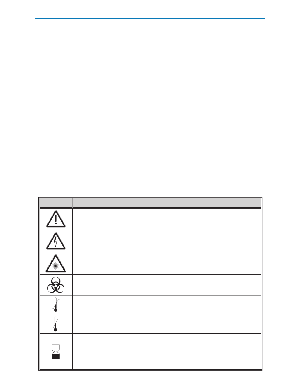
Symbols Symbols can be helpful in reducing the necessity for translating important information
into multiple languages, particularly where space is limited. The following symbols
may be found on components of the i-STAT System.
Symbol Definition
Attention: See instructions for use.
Caution: Risk of electrical shock.
Laser radiation hazard symbol.
Biological Risks.
Temperature limitations. The upper and lower limits for storage are adjacent to
upper and lower arms.
Upper limit of temperature.
The upper limit for storage is adjacent to the upper arm
Use by or expiration date.
An expiration date expressed as YYYY-MM-DD means the last day the product can be
used.
An expiration date expressed as YYYY-MM means the product cannot be used past the
last day of the month specified.
Art: 714363-01K Rev. Date: 03/03/08 1-3
Page 14
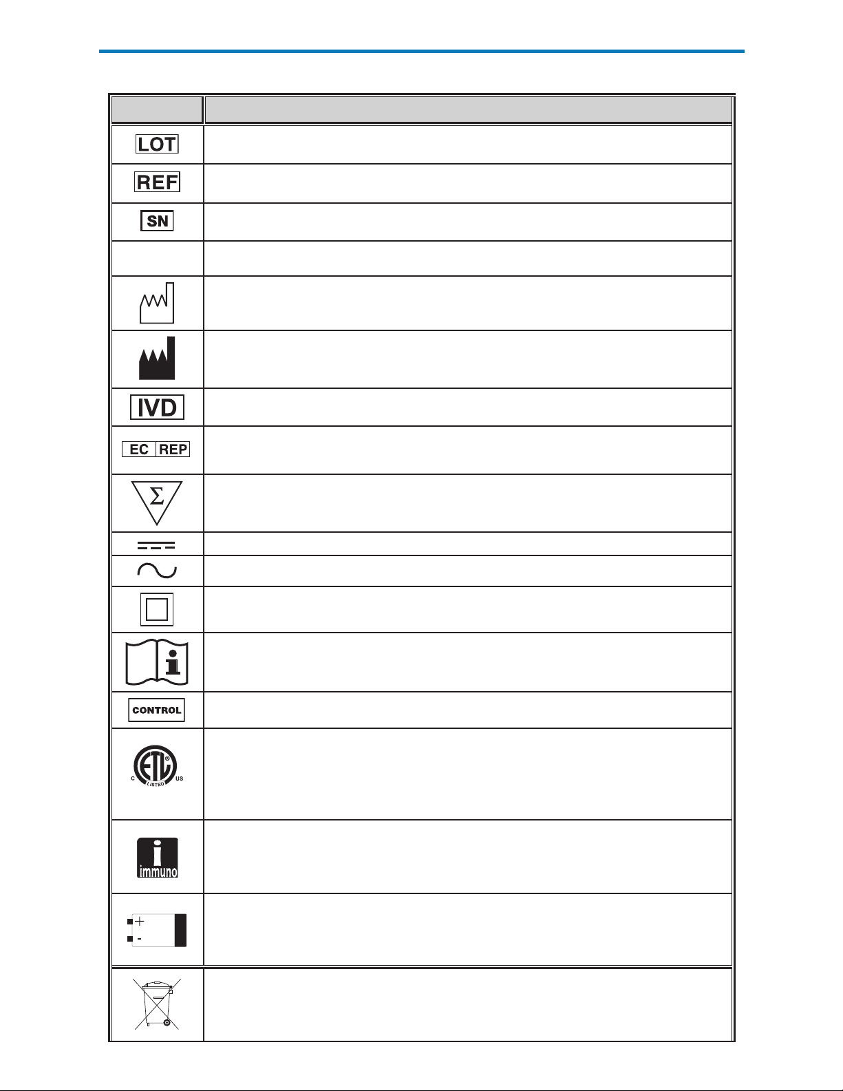
Symbol Definition
Manufacturer's lot number or batch code. The lot number or batch will appear
adjacent to this symbol.
Catalog number, list number, or reference number. The number adjacent to this
symbol is used to reorder the product.
Serial number. The serial number will appear adjacent to this symbol.
MN
Model number. The model number will appear adjacent to this symbol.
Date of manufacture.
Manufacturer
In vitro diagnostic medical device.
Authorized Representative for Regulatory Affairs in the European
Community.
Contains sufficient for < n > tests.
Direct Current (DC)
Alternating Current (AC)
Class II Construction
Consult instructions for use or see System Manual for instructions.
Control
Signifies that the product bearing the ETL Listed mark complies with both U.S. and
Canadian product safety standards:
UL 61010A-1
CAN/CSA C22.2 No. 1010.1-92
i/immuno: Cartridges bearing this symbol must be run on i-STAT analyzers that also
bear this symbol.
Battery: i-STAT 1 Analyzer low battery icon (flashes on lower left side of display
screen).
Separate waste collection for this electrical/electronic item indicated.
1-4 Art: 714363-01K Rev. Date: 03/03/08
Page 15
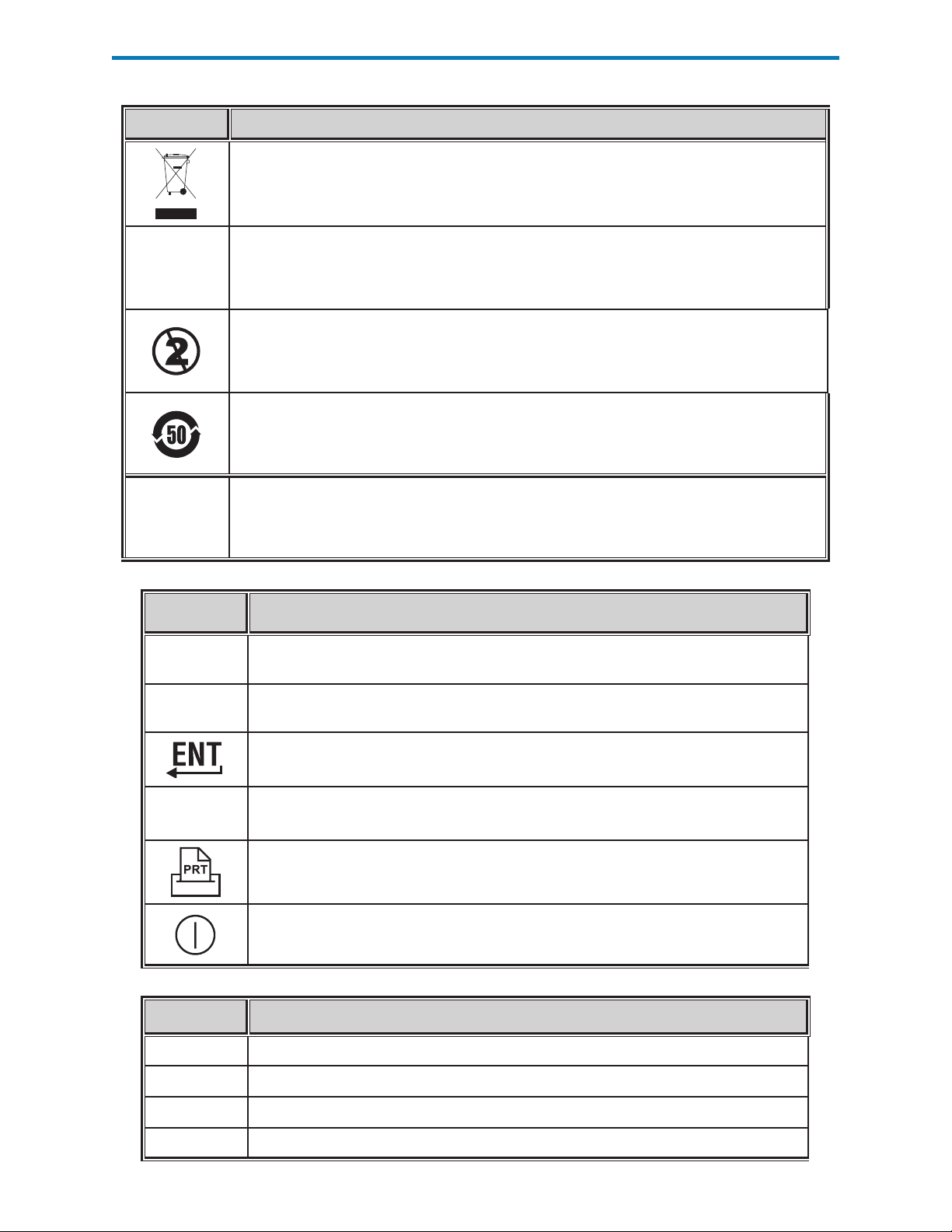
Symbol Definition
Separate waste collection for this electrical/electronic item indicated; Equipment
manufactured / put on the market after 13 August 2005; Indicates compliance with
Article 10(3) of Directive 2002/96/EC (WEEE) for the European Union (EU).
BODxxxx-xx Born On Date: the label BODxxxx-xx defines the year and month of manufacture.
Do not reuse.
This symbol is used for compliance with the China RoHS regulation(s). It indicates
in years the Environmentally Friendly Use Period (EFUP) for the labeled electronic
medical device product
As the Martel Printer is incapable of printing the ↑ or ↓ symbols, this symbol
<< >>
appears on the Martel printout next to results which are outside the action range
limits.
Symbol The following symbols are used on the i-STAT 1 keypad.
SCAN
ABC
MENU
Symbol
DIS
Key used to scan information into the analyzer.
Key used to enter letters.
Key used to enter information.
Key used to access the analyzer's menu.
Key used to print a test record.
Key used to turn the analyzer off and on.
The following symbols are used on the i-STAT Portable Clinical Analyzer Keypad
Key used to activate the display.
ENT
PRT
CLR
Art: 714363-01K Rev. Date: 03/03/08 1-5
Key used to enter information.
Key used to print a test record.
Key used to clear an incorrect entry.
Page 16
Symbol
The following symbols are used on i-STAT Value Assignment Sheets
Mean
R
Symbol TEST
Na
K
Cl
Glu
Lac
Crea
pH
PCO
PO
2
iCa
Range
Sodium
Potassium
Chloride
Glucose
Lactate
Creatinine
pH
2
Partial pressure of carbon dioxide.
Partial pressure of oxygen.
Ionized Calcium
BUN/UREA
Hct
ACTc
Celite ACT
ACTk
Kaolin ACT
PT/INR
Hb
TCO2
HCO3
BE (b&ecf)
AnGap
sO2
cTnI
CK-MB
Urea nitrogen/Urea
Hematocrit
Activated Clotting Time with Celite® activator.
Activated Clotting Time with Kaolin activator.
Prothrombin Time / International Normalized Ratio
Hemoglobin
Total carbon dioxide concentration.
Bicarbonate
Base excess (b for blood, ecf for extra cellular fluid)
Anion Gap
Oxygen saturation
Cardiac Troponin I
Creatine Kinase MB Isoenzyme
BNP
1-6 Art: 714363-01K Rev. Date: 03/03/08
B-type Natriuretic Peptide
Page 17

Warranty
Abbott Point of Care Inc. warrants this medical product (excluding disposable or
consumable supplies) against defects in materials and workmanship for one year
from the date of shipment. If Abbott Point of Care Inc. receives notice of such
defects during the warranty period, Abbott Point of Care Inc. shall, at its option,
either repair or replace products which prove to be defective. With respect to
software or firmware, if Abbott Point of Care Inc. receives notice of defects in
these products during the warranty period, Abbott Point of Care Inc. shall repair or
replace software media and firmware which does not execute their programming
instructions due to such defects. Abbott Point of Care Inc. does not warrant that the
operating of the software, firmware or hardware shall be uninterrupted or error free.
If Abbott Point of Care Inc. is unable, within a reasonable time, to repair or replace
any product to a condition as warranted, Buyer shall be entitled to a refund of the
purchase price upon return of the product to Abbott Point of Care Inc..
Note: Warranty rights may vary from state to state, province to province and
country to country.
Limitations of
Warranty
Selling or Leasing the
i-STAT System
The foregoing warranty shall not apply to defects resulting from:
1 Improper or inadequate maintenance by Buyer or an unauthorized
person,
2
Using accessories and/or consumables that are not approved by Abbott
Point of Care Inc.,
3 Buyer-supplied software or interfacing,
4 Unauthorized repairs, modifications, misuse, or damage caused by
disposable batteries, or rechargeable batteries not supplied by Abbott
Point of Care Inc..
5 Operating outside of the environmental specifications of the product, or
6 Improper site preparation or maintenance.
THE WARRANTY SET FORTH ABOVE IS EXCLUSIVE AND NO OTHER WARRANTY,
WHETHER WRITTEN OR ORAL, IS EXPRESSED OR IMPLIED. ABBOTT
SPECIFICALLY DISCLAIMS THE IMPLIED WARRANTIES OR MERCHANTABILITY
AND FITNESS FOR A PARTICULAR PURPOSE.
If you sell an i-STAT analyzer, please notify Abbott Point of Care Inc. so that
we can enter the new owner into our software update database. If you rent an
i-STAT analyzer and do not intend to provide software updates to the leaser, please
notify Abbott Point of Care Inc. so that we can enter the leaser into our software
database.
Art: 714363-01K Rev. Date: 03/03/08 1-7
Page 18

Page 19

INTRODUCTION
The i-STAT 1 Analyzer is used in conjunction with i-STAT cartridges for the
simultaneous quantitative determination of specific analytes in whole blood and with
the MediSense Precision PCx and PCx Plus Glucose Test Strips for the quantitative
measurement of glucose in whole blood.
Refer to the Cartridge and Test Information section of this manual for information
on analytes that can be measured using i-STAT cartridges.
BEFORE YOU USE THE ANALYZER
i-STAT 1 ANALYZER
2
Install Batteries
Check Date and
Time
Check Software
Customization
Two disposable lithium batteries are supplied with the analyzer. See the Care of the
Analyzer section in this manual for the procedure to install the disposable batteries.
If a rechargeable battery is to be used, the disposable batteries can be used while
the rechargeable battery pack is charged in the Downloader/Recharger. Charge
rechargeable batteries fully before use. See the i-STAT 1 Downloader section for
this procedure. When using a rechargeable battery, store the disposable battery
carrier for possible future use.
Press the On/Off key and check that the date and time at the top of the display are
correct. To change the date and time, see Administration Menu in this section.
Caution
or replaced will have standard CLEW and application software. If a different
CLEW and/or application software is in use in your facility, it must be installed
in new, repaired or replaced analyzers before they are put into use. Check the
Analyzer Status page for the installed CLEW and application software. See under
“Standardization and Calibration” in section 3 of this manual for an explanation
of CLEW.
Analyzers can be customized for many site-specific testing requirements. See the
Customization section for a list of customizable parameters and their default values.
To change the customization profile via the analyzer keypad see “Customization”
under “Administration” in this section of the manual. To change the customization
profile via the Central Data Station, see the “Customization Workspace” in the
Central Data section of this manual.
: New analyzers or analyzers that have been repaired and returned
Caution: New analyzers or analyzers that have been repaired and returned or
replaced will have the factory default settings in the customization profile, as
indicated by the DEFAULT0 on the Analyzer Status page. If analyzers in your facility
do not use the default customization profile, the appropriate customization profile
should be installed before a new, repaired or replaced analyzer is put into use.
The i-STAT 1 Analyzer is shipped with the glucose test strip functionality disabled.
The glucose test strip functionality can be enabled through the Customization
function on the Central Data Station or analyzer.
Older i-STAT 1 analyzers may have the test strip port blocked. The test strip port
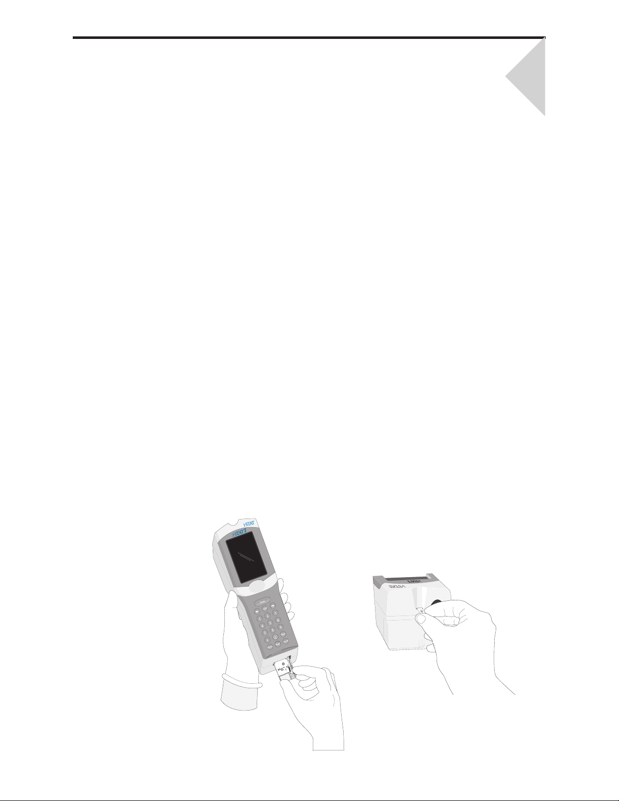
can be unlocked as follows. A small flat-head screwdriver is needed to remove
the plug.
Art: 714364-01H Rev. Date: 03/03/08 2-1
Page 20
1 Hold the analyzer with the test strip port facing you and the display
facing up.
2 Hold the screwdriver with the blade horizontal. Carefully insert the blade
into the horizontal gap under the plug.
3 Pry up gently until the plug pops free. Take care not to force the
screwdriver into the port.
4 Remove the screwdriver and then remove the plug. The plug can be
replaced if necessary.
Perform Quality
Check
DESCRIPTION
Specifications
Use the Electronic Simulator to verify the cartridge-reading performance of new
or repaired analyzers.
Use QC protocols to verify the test strip-reading performance of new or repaired
analyzers.
DIMENSIONS Width 7.68 cm (3.035 in.)
Length 23.48 cm (9.245 in.)
Depth 7.24 cm (2.85 in.)
WEIGHT With rechargeable battery 650 grams (22.9
oz.)
With disposable battery 635 grams (22.4 oz.)
POWER Two 9-volt lithium batteries, or rechargeable
battery.
CALIBRATION
MEMORY/CLOCK BACKUP
POWER
DISPLAY
COMMUNICATION LINK Infrared light-emitting diode (LED)
OPERATING TEMPERATURE
TRANSPORT
TEMPERATURE
RELATIVE HUMIDITY
BAROMETRIC PRESSURE 300-1000 mmHg
LASER SCANNER
Factory: electronic, mechanical, thermal,
pressure
Lithium Battery
Dot matrix supertwist liquid crystal
15-40°C (59-104°F) for Medisense strip
testing
16-30°C (61-86°F) for i-STAT cartridge testing
-10-46°C (14-115°F)
90% (maximum) non-condensing
Complies with U.S. 21 CFR 1040.10 and
1040.11 except for deviations pursuant to
laser Notice No. 50, dated July 26, 2001.
EN 60825-1:1994 + A1:2002 + A2:2001
IEC 60825-1:1993 + A1:1997 + A2:2001
2-2 Art: 714364-01H Rev. Date: 03/03/08
Page 21

Software
All analyzer functions are controlled by application software that can be updated
as additional tests and features are developed. Coefficients used to maintain the
accuracy of cartridge results over time are programmed into the analyzer via CLEW
software updates every four months. See under “Standardization and Calibration”
in section 3 of this manual for an explanation of CLEW.
Note: Calibration information for the glucose test strips is included in the barcode
on the foil packet in which each test strip is packaged. The analyzer requires
that this information be scanned or entered via the keypad before the test
strip can be inserted into the analyzer.
Power
Battery
Compartment
Disposable Batteries
Rechargeable
Battery
There are two power options for the analyzer: disposable and rechargeable. The
analyzer is shipped with two disposable 9-volt lithium batteries and a battery carrier.
Lithium batteries may be ordered from i-STAT or obtained locally. ULTRALIFE
lithium batteries (ULTRALIFE Batteries, Inc., Newark, NY, USA) are recommended.
Only i-STAT rechargeable batteries may be used.
The battery compartment is located at the display end of the analyzer next to
the laser barcode scanner window. The procedure for changing disposable and
rechargeable batteries can be found in the Routine Care of the Analyzer and
Downloader section of this manual.
The analyzer requires two 9-volt lithium batteries. The lifetime for a set of batteries
is mainly dependent on the mix of cartridges in use. Cartridges that require thermal
control consume more energy because of heating. Coagulation and immunoassay
cartridges consume more energy because of the longer test cycle. A minimum
of 400 thermally controlled cartridge uses, about 100 coagulation cartridges, 50
immunoassay cartridges, or about 1,000 glucose test strips can be expected before
replacement is necessary. Backlighting, if used continuously, may reduce battery
life up to 50%. Extensive laser scanning will affect battery life slightly.
The lithium batteries should be removed from the analyzer when long periods, such
as six months, of no use are anticipated.
The analyzer can be powered by a nickel-metal-hydride rechargeable battery. The
battery capacity for one full charge is 30% (minimum) of the capacity of one set of
disposable lithium batteries (see above). If the analyzer is not in use, batteries will
lose approximately 10-30% of their charge over 30 days if not recharged.
Store rechargeable batteries in a cool dry place when not in use.
The battery recharges when the analyzer is placed in a Downloader/Recharger.
The battery pack can be removed from the analyzer and placed in the separate
recharging compartment on the Downloader/Recharger. Full recharge from a
discharged state takes approximately 40 hours. The analyzer will display “Low
Battery” when battery recharge is needed.
Caution: Do not sho rt circui t, inc iner ate or mutilate the recharegable
batteries.
Low Battery
Warning
The analyzer will display “Low Battery” when the On/Off key is pressed. Additionally,
a flashing battery icon will display on the results screens, as well as the Test Menu
and Administration Menu screens when battery replacement is needed. Data is
not lost when batteries are fully discharged.
Art: 714364-01H Rev. Date: 03/03/08 2-3
Page 22
Additional Power
A lithium battery inside the analyzer maintains the clock/calendar and customization
profile. This battery should last seven years.
Cartridge Port
Cartridges and the Electronic Simulator are inserted into the analyzer through the
cartridge port on the keypad end of the analyzer. Unless the analyzer is customized
to require information input before a test, inserting a cartridge or Electronic Simulator
initiates the test cycle (i.e., the analyzer does not need to be turned on first). The
cartridge and test strip ports cannot be used simultaneously.
i-STAT Cartridge Port
Test Strip Port
Precision PCx and PCx Plus Blood Glucose Test Strips are inserted into the analyzer
through the test strip port on the display end of the analyzer when prompted by
the analyzer.
Precision PCx and PCx Plus
Glucose Test Strip Port
Infrared Communication
Window
Battery Compartment Laser Barcode Scanner
Window
2-4 Art: 714364-01H Rev. Date: 03/03/08
Page 23

Infrared
Communication
Window
The Infrared Communication Window provides the analyzer with two-way
communication to the Central Data Station via a Downloader, allows analyzerto-analyzer software updates, and allows analyzer-to-printer communication for
printing.
Thermal Control
Barometric Pressure
Sensor
Cartridge Test Cycle
The analyzer contains a thermal control subsystem of thermistors and heating
contact wires that controls the temperature of the sensors and fluids that come
into contact with the sensors to 37°C. This subsystem is activated automatically
when a cartridge containing tests which require thermal control at 37°C is inserted
into the analyzer.
The analyzer contains a solid-state barometric pressure sensor, which determines
the ambient atmospheric pressure used for the PO2 sensor calibration.
An operator starts a cartridge test cycle either by inserting a cartridge into the
analyzer or by selecting the i-STAT Cartridge option from the Test or Quality Tests
Menu.
The analyzer:
makes electrical contact with the cartridge
identifies the cartridge type
releases calibration fluid to the sensors (when applicable)
mixes sample and reagent (when applicable)
measures barometric pressure
heats the sensors to 37°C (when required by the test )
measures electrical signals generated by the sensors and calibration
fluid (when applicable)
displaces the calibrant solution with sample (when applicable)
measures electrical signals generated by the sensors and sample
accepts the operator and patient IDs scanned or entered by the
operator
accepts chart page information
calculates and displays results
stores results
Strip Test Cycle
An operator starts a test strip test cycle by selecting the PCx Glucose Strip option
from the Test or Quality Tests Menu.
The analyzer:
accepts test strip lot data
prompts the operator to insert the test strip
prompts the operator to apply the sample
measures electrical signals generated by the glucose sensor and sample
accepts the operator and patient IDs scanned or entered by the
operator
accepts chart page information entered by the operator
calculates and displays results
stores results
Art: 714364-01H Rev. Date: 03/03/08 2-5
Page 24
Data Entry
Data that can be scanned into the analyzer or entered via the keypad include:
Operator ID
Patient ID, Proficiency ID, or Simulator ID
Cartridge and Strip Lot Number
Control Lot Number
Cal Ver Kit Lot Number
Comment codes for patient and control
results
Chart Page
Sample Type
Patient Temperature - The analyzer
will interpret numbers between 50.0
and 110.0 as degrees Fahrenheit
and between 10.0 and 45.0 as
degrees centigrade. When a patient
temperature is entered, blood gas
results will be displayed at both 37°C and the patient's temperature.
FIO2
Free Fields: three fields, up to 9 characters each
See the Customization section in this manual for barcode formats recognized by
the analyzer.
Storage of Results The analyzer automatically stores up to 5,000 test records. A test record consists
of:
a set of results
the date and time the test was performed
the cartridge type
all information entered by barcode scanner or keypad including:
Operator and Patient IDs
Lot numbers for controls, cartridges and test strips
Chart page data
Serial number of the Electronic Simulator
the serial number of the analyzer
the number of times the analyzer has been used
the software and CLEW versions installed in the analyzer
the name of the analyzer’s customization profile
Quality Check Codes, which may appear during the test cycle indicating a problem
with the sample, calibration, sensors, mechanical or electrical functions of the analyzer,
are also stored.
The Analyzer Status option under the Administration Menu lists the number of stored
records as “Total” and “Unsent” records. Test records are stored as “Unsent” until
the analyzer uploads data to the Central Data Station at which time the records are
marked as sent. The analyzer can be customized to display a Memory Full prompt or
to disable testing until data is transmitted to the Central Data Station. Otherwise, the
oldest data is overwritten when the memory becomes full. Stored test records can be
reviewed through the Data Review option on the Administration Menu screen described
later in this section.
2-6 Art: 714364-01H Rev. Date: 03/03/08
Page 25
LCD Display and
Backlight
Test results, operator prompts and other messages are displayed on the analyzer’s
LCD Screen. The backlight for the display is turned on and off by pressing the 0
key for one second. The backlight will automatically turn off after ninety seconds
and when the analyzer powers down or is turned off. The backlight cannot be
turned on while data entry screens are displayed.
Audible Indicator
Time Out
The analyzer will beep to indicate:
whenever a key is pressed.
a successful barcode entry.
sample detection on glucose test strip
tests.
results are ready.
a Quality Check Message is displayed.
The analyzer can be customized to disable
beeping when a key is pressed or results or
messages are displayed.
The analyzer automatically turns off after a
certain period of inactivity.
Results displayed: Results are displayed for 2 minutes before the
analyzer turns off provided that a mandatory Comment Code prompt is not
displayed. This Inactivity Time Out default time can be increased using
Customization.
If a mandatory Comment Code prompt is displayed, the analyzer will turn
off after 15 minutes or after the Inactivity Time Out, whichever is greater. In
the case of a missed required Comment Code, results will be stored and “_
_ _” will be entered as the Comment Code.
Prompting for mandatory data when results are ready for display:
The analyzer will turn off after 15 minutes or after the Inactivity Time Out,
whichever is greater, if there is no response to a mandatory data prompt.
A mandatory data prompt is a prompt for information that must be entered
before pending results are displayed.
In the case of a missed mandatory data prompt, results will not be stored
and the test record will state “Test Cancelled by Operator.”
Waiting for insertion of cartridge: After the prompt “Insert Cartridge”
is displayed, the analyzer will wait 15 minutes for the operator to insert a
cartridge unless the analyzer is in the Proficiency path, in which case the
analyzer will wait 5 minutes. If a cartridge is not inserted, the analyzer will
turn off. This timeout cannot be customized.
Waiting for insertion of test strip: After the prompt “Insert Strip” is
displayed, the analyzer will wait 2 minutes for the operator to insert a test
strip. If a test strip is not inserted, the analyzer will turn off. This timeout
cannot be customized.
Other: The analyzer will turn off after 2 minutes of inactivity (no keys pressed)
in all other circumstances.
Art: 714364-01H Rev. Date: 03/03/08 2-7
Page 26
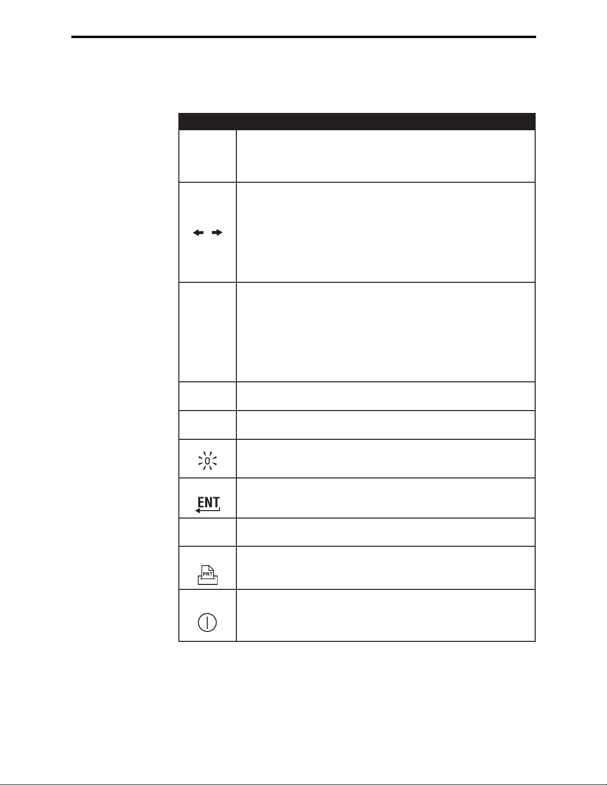
Keypad There are 19 keys located directly below the display. When using the keypad to enter
information, the number of dashes in the data entry line will indicate how many characters
can be entered on the line. The dash where the next entry will be placed will flash.
Key Function
Activates the barcode scanner. Information that can be entered
SCAN
ABC
0 – 9
•
into the analyzer via the scanner includes: operator ID, patient ID,
control, cartridge and test strip lot number, patient chart data and
comment codes.
Used to move the cursor on the Set Clock screen and to move
up and down the alphabet when the ABC key is pressed. The
(right arrow) key is used as a page key to move from one
screen to the next. When Patient ID Recall is enabled, the
key will recall the last patient ID when the analyzer is prompting
for Patient ID. The (left arrow) key is used to backspace and
clear keypad entries, and to move backward through the screens
within a menu.
Used to enter alpha characters on data entry screens. When
the ABC key is pressed the letter A is entered. The arrow keys
are used to move up and down the alphabet. To enter a second
letter, press the ABC key once to move to the next position and
again to enter an A. To enter a number after a letter, press a
numbered key. To erase a letter, press the ABC key to move to
the next position, then use the key to backspace and clear the
letter.
Used to enter digits on data entry screens and to select menu
options and stored records.
Enters a decimal point or a comma separator according to the
analyzer’s Customization Profile.
Used to turn the screen backlight on and off.
Enter Used to respond to a prompt to complete an action, such as
entering an operator or patient ID via the keypad.
MENU
Print Used to print either directly to the portable printer or to the
On/Off
2-8 Art: 714364-01H Rev. Date: 03/03/08
Used to return to the previous menu and switch between the Test
and Administration Menus.
portable printer attached to a Downloader.
Turns the analyzer on or off. When the analyzer is on, the On/Off
key must be pressed for a second to turn the analyzer off. This
key is inactive when a test is in progress and when the analyzer
is prompting for mandatory data.
Page 27

i-STAT 1 Menu Tree
There are two main menus: The Test Menu and the Administration Menu. If the
glucose test strip function is disabled, test strip options will not be displayed.
Test Menu Administration Menu
1- Last Result 1. Analyzer Status Temp
2- i-STAT Cartridge Pressure
3- PCx Glucose Strip 1- Patient Battery
2- Control Uses
Serial
CLEW
Version
Custom
Stored Records
2- Data Review 1-Patient
2-Control 1- i-STAT Cartridge
2- PCx Glucose Strip
3- All
3-Proficiency 1- i-STAT Cartridge
2- PCx Glucose Strip
3- All
4-Cal Ver 1- i-STAT Cartridge
2- PCx Glucose Strip
3- All
5- Simulator
6- All
7- List
3-Quality Tests 1-Control 1- i-STAT Cartridge
2- PCx Glucose Strip
2- Proficiency 1- i-STAT Cartridge
2- PCx Glucose Strip
3- Cal Ver 1- i-STAT Cartridge
2- PCx Glucose Strip
4- Simulator
4- Customization 1- View
2-Change 1- Analyzer
2- ID Entry
3- Patient Tests
4- QC Tests
5- Results
6- Password
7- Restore Factory
Settings
5- Set Clock
6- Transmit Data 1- Most Recent
2- This Month
3- Last Month
4- All
7-Utility 1- Send Software
2- Clear Memory
Art: 714364-01H Rev. Date: 03/03/08 2-9
Page 28
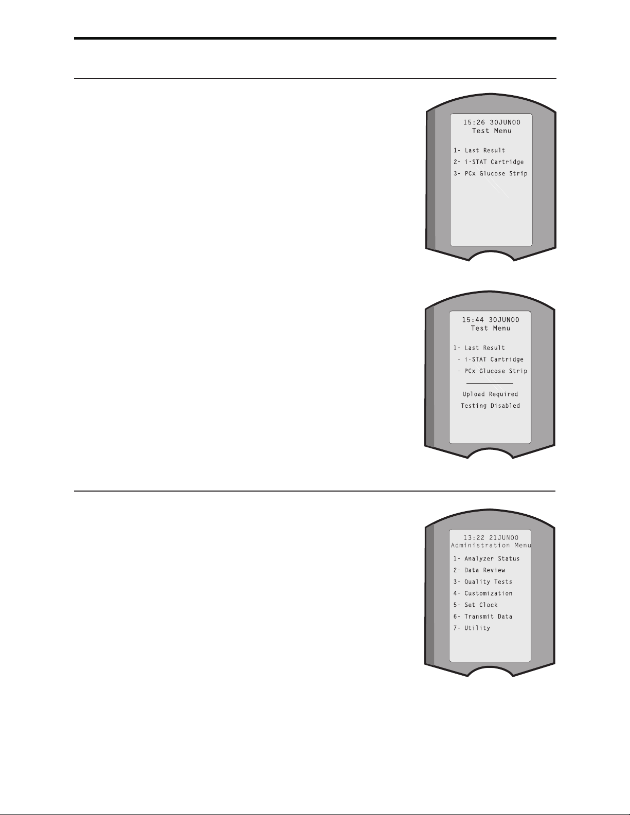
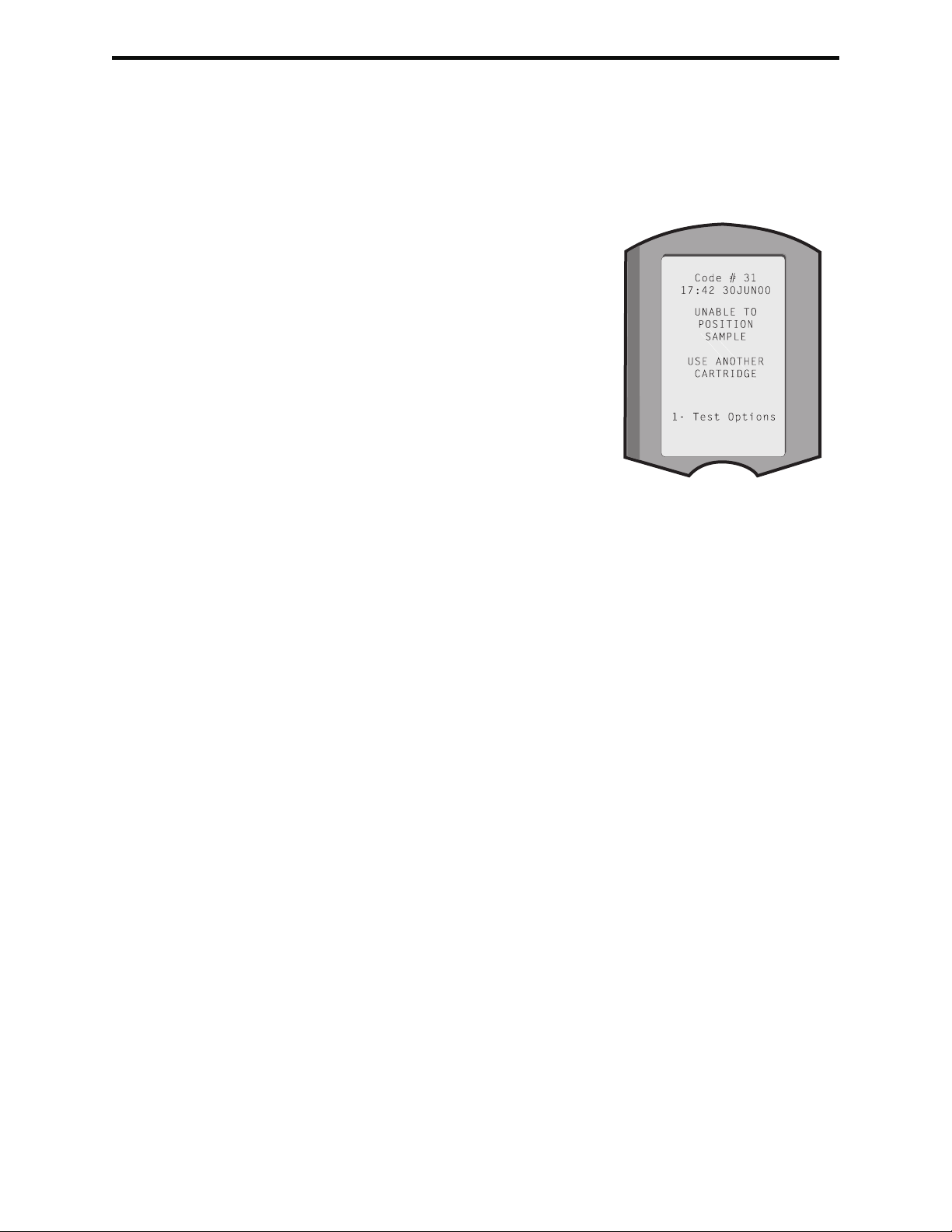
TEST MENU
The Test Menu is displayed when the analyzer is
turned on using the On/Off key.
The options are:
1 - Last Result
2 - i-STAT Cartridge
3 - PCx Glucose Strip
1 - Patient
2 - Control
Options 2 and 3 are used for testing patient
samples. For the glucose test strip, controls can
also be tested from the Test Menu. Testing controls
from the Test Menu rather than option 3 – Quality
Tests under the Administration Menu may be more
convenient for end users who test glucose test strip
control samples on a daily basis.
Note: If the analyzer is customized with test strip
testing disabled, test strip options will not
be displayed. If the analyzer is customized
to disable testing under certain conditions,
the disabled option will be listed without
its number so that it cannot be selected.
ADMINISTRATION MENU
Overview
The Administration Menu is accessed by pressing
the Menu key from the Test Menu screen. The
options are:
1 - Analyzer Status
2 - Data Review
3 - Quality Tests
4 - Customization
5 - Set Clock
6 - Transmit Data
7 - Utility
2-10 Art: 714364-01H Rev. Date: 03/03/08
Page 29
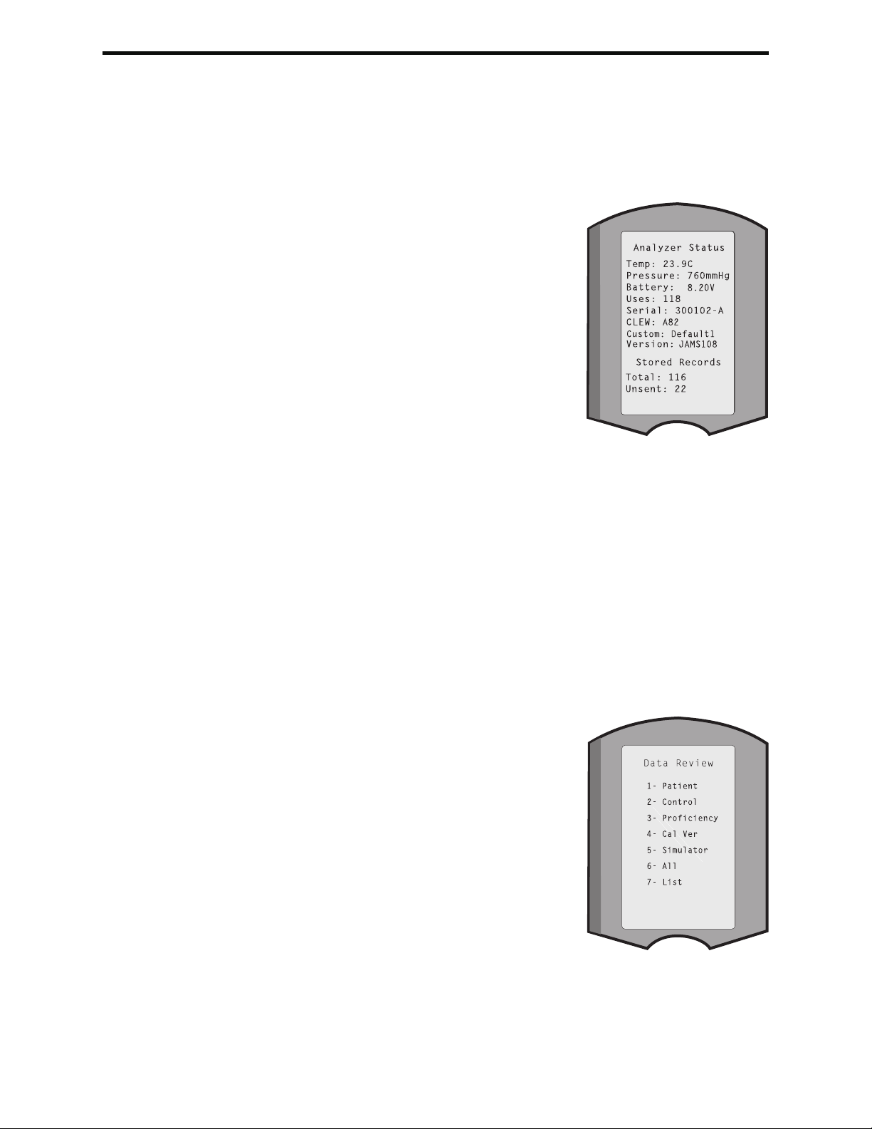
Analyzer Status
The Analyzer Status screen contains information about the condition or “status” of
the analyzer. Fresh readings are made whenever this option is selected.
Temp Room temperature.
Pressure Barometric pressure.
Battery Battery voltage.
Uses Total number of cartridge,
simulator and test strip
test cycles, whether or not
results reported.
Serial Serial number of the
analyzer.
CLEW Version of standardization
data installed in the analyzer.
Version Version of application
software installed in the
analyzer.
Custom Customization profile name.
Stored Records Total: The number of test records in the analyzer’s
memory. The maximum storage capacity is 5,000
test records, which include records with results and
Quality Check Codes for patients and controls both
liquid and electronic.
Unsent: The number of test records that have not
been transmitted to the Central Data Station.
Data Review
The Data Review function allows the operator to review stored results by the
categories listed below. The number of test records stored is indicated at the
bottom center of the screen as x/y where x is the record on the screen and y is
the total number of stored records in the selected category. The 1 and 2 keys are
used to scroll through the stored records as indicated on the bottom right and left
of the screen. The most recent test record is always in the first position. The right
arrow key is used to page through the screens of the displayed record.
1 - Patient The records for a patient
are recalled by scanning or
entering via the keypad the
Patient ID. If no Patient ID is
entered, all patient tests are
recalled.
2 - Control 1 – i-STAT Cartridge
2 – PCx Glucose Strip
3 - All
3 - Proficiency 1 – i-STAT Cartridge
2 – PCx Glucose Strip
3 - All
4 - Cal Ver 1 – i-STAT Cartridge
2 – PCx Glucose Strip
3 – All
5 - Simulator All external and internal Electronic Simulator records.
6 - All All test records in the analyzer’s memory.
Art: 714364-01H Rev. Date: 03/03/08 2-11
Page 30
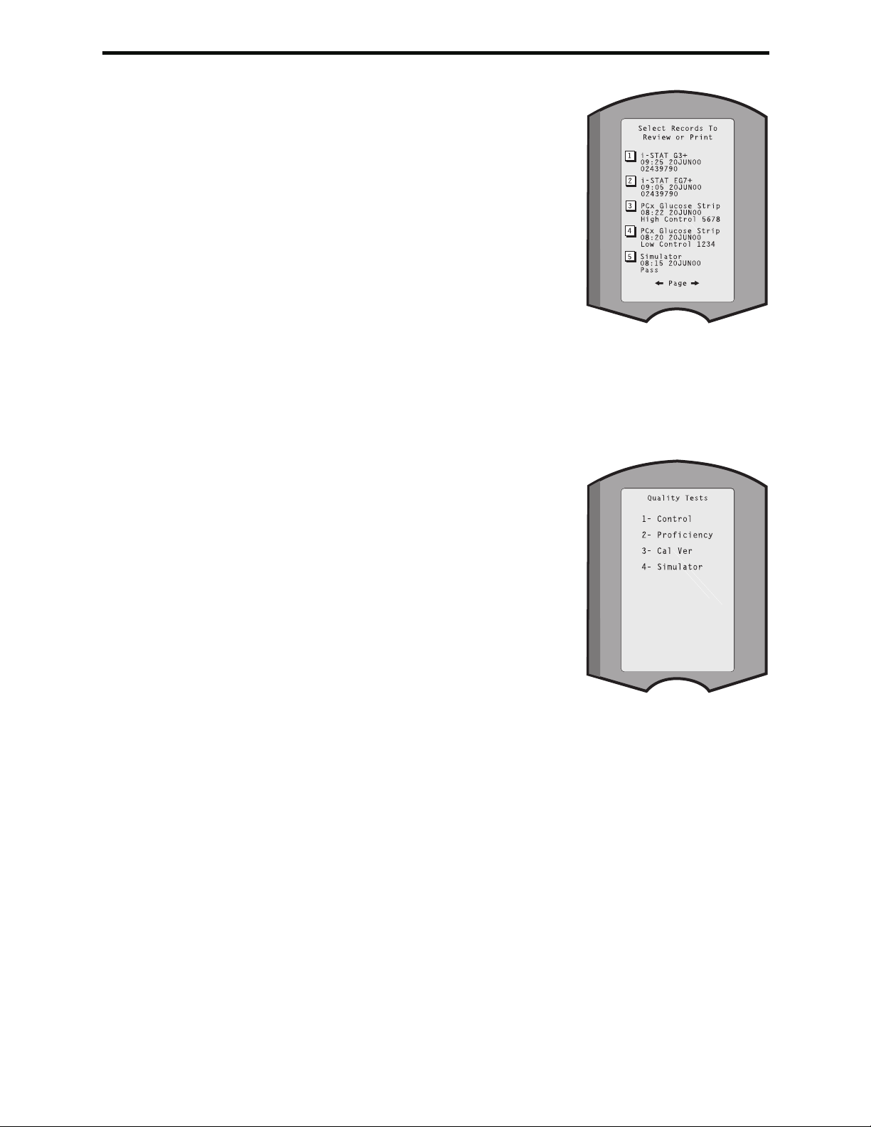
7 - List Records are listed with
Cartridge type or PCx Glucose
Strip, date and time of test,
and patient ID, control lot,
proficiency ID, or Cal Ver lot
and test level as applicable.
Any number of test records
can be selected for viewing
or printing using the number
keys. Pressing the number
key corresponding to a record
selects a record; pressing the
number key a second time
deselects the record.
To view one or more records,
select the records and press
the Enter key. To print records, select the records and
press the Print key.
Quality Tests
Non patient tests can be initiated from the Quality Tests menu. Options are:
1 - Control
2 - Proficiency (external quality control)
3 - Cal Ver (Calibration Verification for
cartridges and Linearity Test
for test strips)
4 - Simulator (cartridge-reading function
only)
When options 1 - 3 are selected, the operator
further selects:
1 – i-STAT Cartridge
2 – PCx Glucose Strip
When testing is initiated from one of these options,
the analyzer prompts the operator to scan or
enter the Operator ID; the Control Lot Number,
Proficiency ID, Cal Ver Kit Lot Number, or Simulator ID as applicable; and the
Cartridge Lot Number or Test Strip Lot Number as applicable.
When the Quality Tests option is used, results can be reviewed according to the
corresponding options under the Data Review option.
Note: The Test Menu option for test strips includes both a Patient and Control
option. Results for test strip controls run from the Test and Quality Tests menus
are stored together.
2-12 Art: 714364-01H Rev. Date: 03/03/08
Page 31

Customization
Analyzers can be customized for site-specific testing characteristics and
requirements. A complete list of customizable parameters and their default values
can be found in the Customization section. An analyzer can be customized via the
keypad or via the Central Data Station. Items that cannot be customized via the
analyzer’s keypad are operator lists, test strip lists, reference and action ranges,
sample types and order of items on the Chart page.
The Central Data Station’s Customization function can be used to create one
customization profile for all analyzers or different profiles for different locations.
When the Customization function is enabled, the profiles are transmitted to the
analyzers when they are placed in a Downloader.
Caution: If location specific customization profiles are created, analyzers should
not be moved from one location to another unless they are re-customized for
the new location. This is especially important if “CPB: Automatically Adjust” or
“CPB: Do Not Adjust” is included in a location-based customization profile. The
CPB function adjusts hematocrit and hemoglobin results for the dilutional affect of
pump fluid during cardiopulmonary bypass surgery. If an analyzer customized for
the CVOR as “CPB: Automatically Adjust” is used for patients who are not on the
pump, hematocrit results will be reported falsely high. If an analyzer customized
as “CPB: Do Not Adjust” is used for patients who are on the pump, hematocrit
results will be reported falsely low. For details on the CPB function, see the Theory
section of this manual.
It is recommended that only one method, the Central Data Station or the keypad,
be used to customize all analyzers within a site. If both methods are in use, and the
Customization function is not disabled on the Central Data Station, any changes
made to the profile of an analyzer via the keypad will be overwritten the next time
the analyzer is placed in a Downloader.
The customization profile of an analyzer is identified in the Customization option
under the Administration Menu on the analyzer. DEFAULT0 indicates that the
analyzer has factory settings. When an analyzer has been customized via the
Central Data Station (CDS), the name assigned to the profile by the CDS is listed.
If the default or CDS profile is changed on the analyzer, the profile is listed as
00000000.
Note: The i-STAT Portable Clinical Analyzer and the Philips Medical Systems Blood
Analysis Module can be customized only from the Central Data Station. However,
not all customizable features apply to these two analyzers. See the i-STAT System
Manual for the i-STAT Portable Clinical Analyzer for customizable features for this
analyzer and the Blood Analysis Module.
Art: 714364-01H Rev. Date: 03/03/08 2-13
Page 32

Viewing the
Customization
Profile
Select 4- Customization from the Administration Menu, select 1- View then select
from the Customization Menu:
1 - Analyzer
2 - ID Entry
3 - Patient Tests
4 - QC Tests
5 - Results
Select a category to review. Use the ← and → keys to scroll through the preferences
for each category and use the ← key to return to the Customization menu.
The Customization review option on the analyzer does not display the certified
operator list or the valid test strip lot list. These items can be viewed on the Central
Data Station.
Changing the Profile
To customize via the analyzer keypad, select 4- Customization from the
Administration Menu, then select 2- Change. If the analyzer has already been
customized with a password, enter the password. If not, press the Enter key. (It
is recommended that the Change function be password protected). Then make
selections from the Customization menu. To change a setting, select the item by
pressing the number key correponding to the item, then select the setting. Use
the → key to view all items. After all items have been set, turn the analyzer off to
save and activate the settings.
Note:
Outside the USA, the following changes should be considered:
language, unit set, date format and decimal separator.
1 - Analyzer
first page
1 Language
2 Date Format
3 Sound
4 Auto-transmit
5 Memory Full
second page
1 Batch Mode
2 Inactivity Timeout
3 Upload Schedule
4 PCx Glucose Test Strip
5 Clock Password
third page
1 Sync Clock
2-14 Art: 714364-01H Rev. Date: 03/03/08
Page 33

2 - ID Entry
1 – Operator
first page
1 Minimum Length
2 Maximum Length
3 Repeat ID
4 Manual Entry
5 Code I2of5
second page
1 Code 128
2 EAN-8, EAN-13
3 Codabar
4 Code 93
5 Code 39, Full ASCII
third page
1 Code 39, Check Digit
2 Truncate First x Digits
3 Truncate Last x Digits
4 Print ID
2 – Patient
first page
1 Minimum Length
2 Maximum Length
3 Repeat ID
4 ID Recall
5 Manual Entry
second page
1 Code I2of5
2 Code 128
3 EAN-8, EAN-13
4 Codabar
5 Code 93
third page
1 Code 39, Full ASCII
2 Code 39, Check Digit
3 Truncate First x Digits
4 Truncate Last x Digits
3 - Patient Tests
first page
1 Cartridge Auto-chart
2 Strip Auto-chart
3 Cartridge Information
4 Cartridge Barcode
5 Cartridge Lot Number
second page
1 Comment Code, In Range
2 Comment Code, Out of Range
3 Strip Sample Type
4 Result Output
5 Downloader Lockout
Art: 714364-01H Rev. Date: 03/03/08 2-15
Page 34

4 - QC Tests
1 – Simulator
1 External Simulator
2 External Simulator Schedule Option
3 Internal Simulator
4 Internal Simulator Schedule Option
2 – Strip Controls
1 Schedule
2 Mid Level Control
3 Comment Code, In Range
4 Comment Code, Out of Range
5 - Results
1 – Units and Ranges
2 – Options
first page
1 Decimal Separator
2 Test Selection
3 Hematocrit (CPB and EDTA)
4 Base Excess
5 ACT-C Cal Options
second page
1 ACT-K Cal Options
2 Print Reference Ranges
6 - Password
7 - Restore Factory Settings
2-16 Art: 714364-01H Rev. Date: 03/03/08
Page 35

Set Clock
If the analyzer is customized with a password, the Set Clock function will be password
protected. If a password has not been assigned, pressing the Enter key will display the
time and date screen. Use the arrow keys to move the cursor
to the digit to be changed. Use a number key to change the
digit. Press Enter to accept the changes or Menu to cancel
the changes. An invalid entry, such as 13 for a month, will not
be accepted.
The format of the date on this screen can be customized using
the Central Data Station Customization function, as mm/dd/yy
or dd/mm/yy. The analyzer recognizes years in which February
has 29 days.
The analyzer can be customized using the Central Data Station
to synchronize or update the real time clock to the Central Data
Station's clock at the time of each download. This option eliminates the need to reset
the analyzer's clock at the beginning and end of Daylight Saving Time. Otherwise, the
clock must be manually changed for Daylight Savings Time changes.
Transmit Data
Utility
Unsent test records are automatically transmitted to the Central Data Station when an
analyzer is placed in a Downloader or Downloader/Recharger. In some cases it may be
desirable to have the capability to retransmit data. The Transmit Data function allows
transmission of data in the following manner:
1 – Most Recent
2 – This Month
3 – Last Month
4 – All
Most Recent is the result from the last cartridge or test strip
tested.
The analyzer can be customized using the Central Data Station
to apply a date range limit to the Transmit All functions.
Auto-transmit is temporarily disabled when the Transmit Data option is selected to
allow the user to control transmission of data.
The Utility menu can be password protected using the Customization function on the
analyzer or Central Data Station.
1 – Send Software: Allows the analyzer to transmit
software to another analyzer. See the Software
Update section of this manual.
2 – Clear Memory: Erases results from the analyzer’s
memory. Options are:
1 – Previous to 01MMMYY (where MMMYY is
current month and year, such as 01JUN00)
2 – Previous to 01mmmyy (where mmmyy is
previous month and year, such as 01May00)
3 – All
4 – Cancel
3 – Receive Software: Allows users to remotely
request a JAMS and CLEW update for the analyzer from the CDS. See
section 18 (Updating Software) for full details.
Art: 714364-01H Rev. Date: 03/03/08 2-17
Page 36

LASER BARCODE SCANNER
Laser Barcode
Scanner
Laser Specifications
Warning Labels
The barcode scanner is used to scan barcode information into the analyzer.
Parameters that can be entered into the analyzer via the scanner include: operator
and patient IDs, control, cartridge and test strip lot numbers, comment codes and
patient chart data. The laser beam emerges from the recessed window on the front
of the analyzer adjacent to the battery compartment. The laser beam automatically
turns off after 3-4 seconds or after the barcode is successfully scanned.
The barcode scan engine is manufactured by Symbol Technologies Corporation.
The scan engine contains a laser diode that emits laser radiation at a frequency
of 650 nm. The scan engine outputs power (i.e., the power output of the engine
if removed from this product) up to 1.9 mW in scanning mode. The scanner in
this product only operates when the Scan key is pressed. Symbol Technologies
Corporation intends this engine to be used in a Class 2 device.
Warning labels are shown below. The warning labels are located on the back or
under-side of the analyzer, as shown. The location of the laser window from where
the analyzer emits the laser beam is also shown below.
Laser Barcode Scanner
Window
2-18 Art: 714364-01H Rev. Date: 03/03/08
Page 37

Caution
Do not open the analyzer.
The analyzer may only be opened by factory authorized
service personnel. Class 2 laser radiation when open; DO NOT stare into the
laser aperture or the laser beam, or point the laser beam at other persons.
Use of controls, adjustments or performance of procedures other than those
specified herein may result in hazardous laser radiation exposure.
Class 2 laser scanners use a low power, visible light diode. As with any bright light
source, such as the sun, the user should avoid staring directly into the laser beam.
Momentary exposure to a Class 2 laser is not known to be harmful.
Procedure Before scanning, check to see what information is required by the displayed prompt.
Hold the analyzer 3-12 inches (2.5 – 30.5cm) from the barcode to be scanned.
An angle of about 10 degrees from perpendicular is best. Hold the analyzer and
place the object to be scanned on a flat surface or, place the analyzer on a flat
surface and hold the object in front of the analyzer. Avoid accidentally scanning
other nearby items. Avoid pointing the beam into anyone’s eyes.
STEP ACTION
1 Press and hold down the Scan key to start the barcode scanner. The
analyzer emits a visible red beam.
2 Position the analyzer and barcode so the beam forms a red line that
spans the entire barcode. Increasing distance between the barcode and
analyzer lengthens the red line. The analyzer does not need to touch the
barcode.
3 When the analyzer accepts the barcode, it will beep in acknowledgement
and automatically turn off the beam. The beam will also turn off after 3-4
seconds.
4 View the data that was scanned by the analyzer and verify that it is
correct.
5 Release the Scan key.
Note: If the Scan key is released as soon as the beep is heard, the next prompt will
be displayed and the information scanned will not be able to be viewed.
PROMPTS AND MESSAGES
Prompts
Either before or during the testing cycle, the analyzer will display prompts that
require an operator action or keypad entry, such as “Enter Operator ID.” Prompts
are described in the manual when used. Some prompts require input before results
are displayed. Prompts for the following information are mandatory:
Operator ID
Patient ID
Lot Number for Test Strips
Lot Numbers for Quality Tests
Art: 714364-01H Rev. Date: 03/03/08 2-19
Page 38

Startup Messages
When the On/Off key is pressed the analyzer may display one or more startup
messages. A startup warning message indicates an action that should be taken
in the near future to maintain the analyzer in working condition. If the analyzer is
customized to disable testing under certain conditions, a startup lockout message
indicates the action that must be taken before testing is re-enabled.
Quality Check
Messages
If the analyzer detects a problem during power on, a Quality Check message will
be displayed indicating the action that must be taken before testing can begin.
A Quality Check message will also be displayed and testing halted if the analyzer
detects a problem during the test cycle.
Startup messages and Quality Check messages are described in the Troubleshooting
section of this manual. “Upload Required, Testing Disabled” is an example of a
startup lockout message, “Battery Low ” is an example of a startup warning
message, and “Unable to Position Sample” is an example of a quality check failure
during the testing cycle.
Note: The “Cartridge Locked” or “Simulator Locked” prompt is always displayed
when a cartridge or Electronic Simulator is inserted into the analyzer. Any
attempt to remove a cartridge or Electronic Simulator before this prompt
is removed from the screen may cause damage to the analyzer.
2-20 Art: 714364-01H Rev. Date: 03/03/08
Page 39

i-STAT CARTRIDGE
3
Contents
The unit-use disposable cartridge contains many of the subassemblies typically
found in complex laboratory systems. Microfabricated thin film electrodes or
sensors are assembled in unit-use cartridges containing:
• calib rant solution in cartridges wi th senso rs for blood gases,
electrolytes, chemistries and hematocrit
• reagents in cartridges with sensors for coagulation
• sample handling system
• waste chamber
• an array of miniaturized sensors
• conductive pads to make electrical contact with the analyzer
• heating elements in cartridges requiring thermal control at 37 °C
See the Cartridge and Test Information Sheets for test-specific details.
The following diagram shows how a typical blood gas/chemistry cartridge is
constructed.
Art: 714365-01C Rev. Date: 07/12/04
3-1
Page 40

Sample Handling
System
Contact
Sensors
Pads
Part Function
Sensor Channel The sensor channel directs the sample from the
sample chamber to the sensors. An extension of this
channel becomes a waste chamber to receive the
calibrant solution as it is displaced by the sample.
Air Chamber An air chamber is located in blood gas/electrolyte/
chemistry/hematocrit cartridges between the sample
chamber and sensor channel. This creates an air
segment between the calibrant solution and the
sample to prevent the two from mixing. The size of
the air segment is monitored by the analyzer.
Sample Chamber The sample chamber includes the sample well and
the channel leading from the well up to the fill mark.
When filled, the sample chamber contains sufficient
sample for testing. Sample volume and placement are
monitored by the analyzer.
Bladder The bladder (concealed by the label) is connected to
the sample well. The analyzer presses on the bladder
to displace calibrant solution from the sensors, to
move the sample from the sample chamber to the
sensors or to mix sample and reagents.
Sensors
Sample Well
Snap Closure The snap closure creates an airtight seal necessary
for proper fluid movement within the cartridge.
The closure also ensures that calibrant and sample
remain contained within the cartridge during the
testing cycle and subsequent disposal. Immunoassay
cartridges, such as cTnI, use a plastic slide enclosure
clip.
Air Vent An air vent on the underside of the cartridge, beyond
the fluid front, allows the calibrant and the sample to
flow forward, but not out of the cartridge.
Waste Chamber A waste chamber (beneath the cartridge label) holds
calibrant fluid after it has been used.
The sensors are electrodes microfabricated on silicon chips. Electrodes have
chemically sensitive coatings such as ion-selective membranes and enzyme
layers. In cartridges that perform coagulation tests, reagents, such as clot
activators, are coated on the plastic above the sensors. Each sensor is connected
to a contact pad by a signal line. The sensors respond to the calibrant
solution and the sample by producing measurable signals related to analyte
concentration. The performance characteristics for each sensor are described
in the Cartridge and Test Information section. The section on theory describes
the measurement principles.
3-2
Contact Pads
Heating Elements
The contact pads conduct the signals generated by the sensors to the analyzer.
In order to function properly, care must be exercised not to contaminate the
contact pads during cartridge handling.
Cartridges that require thermal control at 37°C include heating elements on the
underside of the sensor chips which are contacted and heated by the analyzer’s
thermal probes.
Art: 714365-01C Rev. Date: 07/12/04
Page 41
Standardization and
Calibration
Standardization is the process by which a manufacturer establishes “true”
values for representative samples. The sensors in the i-STAT cartridges are
standardized against plasma methods used by major laboratory systems or,
for blood gases, against tonometry. A multi-point calibration curve, the
slope or sensitivity of which is defined by coefficients in the CLEW software,
is derived for each sensor by this standardization pro cess. These calibration
curves are stable over many lots and only need to be adjusted if a change in a
manufacturing process affects the curve or if the relationship between results
on the i-STAT System and other major laboratory systems drifts. For the
convenience of users, CLEW updates are scheduled three times a year.
A one-point calibration is performed each time a cartridge requiring calibration
is used. During the first part of the testing cycle, the calibrant solution is
au to mat i cal ly released from its foil pack and is positioned over the sensors.
The signals produced by the sensors’ responses to the calibrant solution
are measured. This one-point calibration adjusts the offset of the stored
calibration curve. Next, the analyzer automatically moves the sample over the
sensors and the signals produced by the sensors’ responses to the sample are
measured. While coefficients are used rather than graphic calibration curves,
the cal cu la tion of the result is equivalent to reading the sample’s concentration
from adjusted calibration curve.
Packaging
Each cartridge is sealed in a foil pouch or clear plastic portion pack for
protection during storage.
Labeling on the carton, box and pouch/portion pack identify:
• the panel name.
• the tests included in the panel.
• the lot number.
• the expiration date of the cartridge.
If the pouch/portion pack has been punctured, the cartridge should not be
used.
Rev. Date: 07/12/04 Art: 714365-01C
3-3
Page 42

Storage Conditions
The main supply of cartridges should be stored at 2-8°C (35-46°F). Cartridges
must be at room temperature before removing them from their pouches. Allow
5 minutes for an individual cartridge and one hour for a box of 25 cartridges
to come to room temperature. Cartridges in use may be stored at room
temperature (18-30°C or 64-86°F) for two weeks. The cartridge box contains a
line used to indicate the two-week room temperature expiration date.
Disposal
Although the sample is contained in the cartridge, cartridges should be
disposed of as biohazardous waste, according to local, state, and national
regulatory guidelines.
3-4
Art: 714365-01C Rev. Date: 07/12/04
Page 43
PRECISION PCx and PCx™ Plus BLOOD GLUCOSE TEST STRIPS
4
Detailed Information
Packaging
See the package insert included with each box of glucose test strips for
information not included in this manual:
² Summary and Principle
² Reagents
² Storage and Handling
² Precautions
² Expected Results for Precision, Precision•G®, MediSense®
Control Solutions
² Limitations of the Procedure
² Performance Characteristics
Each test strip is wrapped in a foil packet with a barcode label. This label holds
the calibration information about the test strip, including:
² Lot number
² Expiration date
² Expected control solution ranges
² Lot-specic calibration information
Example of test strip barcode label
Disposing of Waste
Art: 714366-01B Rev. Date: 03/29/04
Discard used test strips in an approved biohazard container.
Page 44

4-2
Art: 714366-01B Rev. Date: 03/29/04
Page 45

Art: 714367-01B
Rev. Date: 07/18/03
5-1
The external Electronic Simulator is a stable electronic device, which is inserted
into the cartridge port. The test cycle for the external Electronic Simulator is
about 60 seconds. (The test cycle for the internal simulator is shorter because
it shares the initial part of the test cycle with the cartridge.)
Overview
The Electronic Simulator, external and internal, is a quality control device
for the analyzer’s cartridge signal-reading function. It simulates two levels of
electrical signals that stress the analyzer’s cartridge signal detection function
both below and above measurement ranges.
While the analyzer performs internal electronic checks and calibration during
each test cycle, the Electronic Simulator test provides an independent check
on the ability of the analyzer to take accurate and sensitive measurements of
voltage, current and resistance from the cartridge. An analyzer will pass or
fail this electronic test depending on whether or not it measures these signals
within limits specified in the analyzer software.
The schedule for the Electronice Simulator can be customized to meet local,
state, or national accreditation requirements. A reminder message for the
operator to run the external simulator can be set by the number of hours on
the i-STAT Portable Clinical Analyzer and by the hours or tests on the i-STAT 1
Analyzer. The schedule for the automatic internal Electronic Simulator can be
set by the number of hours on the i-STAT Portable Clinical Analyzer and by the
hours or tests on the i-STAT 1 Analyzer. For details and lockout options, see the
Customization section of this manual.
The Electronic Simulator test will fail if high humidity interferes with the
measurements. Therefore it is not necessary to record humidity where the
analyzers are in use.
When the specified time has elapsed since the last Electronic Simulator test
cartridge is inserted before the sample is tested, adding about 20 seconds to the
testing cycle.
Page 46

5-2
Art: 714367-01B
Rev. Date: 07/18/03
Even when the internal Electronic Simulator is enabled, an external Electronic
Simulator is needed:
to validate an internal simulator failure.
to reset the internal simulator schedule if a
simulator test might interrupt testing, such
as in a CVOR.
Note: CVOR = Cardiovascular Operating Room
for on-demand testing at any time.
to perform the thermal probe check.
to access the Proficiency and Calibration Verification test paths on
the i-STAT Portable Clinical Analyzer.
The external Electronic Simulator should be stored in the static-free box in
which it is shipped and the blue cap should be replaced after each use to
protect the contact pads.
Stored Result
The results of the Simulator test are stored as a distinct record in the analyzer
and can be transmitted to the Central Data Station
Use of the Electronic Simulator is described further in the Quality Control
section of this manual.
Operating Characteristics
Width 7.0 cm
Weight
85 g
Operating
Temperature
Same as Analyzer
being tested
Operating Ambient
0-90% RH
(as shipped)
Storage Temperature
-20-50˚C
(-4-122˚F)
Operating
Characteristics
Cleaning the
Simulator
Before cleaning, cover the connector area with the blue rubber boot. This
will minimize the possibility of any cleaning fluid getting into the simulator
housing, thus contaminating the internal circuitry.
Clean the simulator with a gauze pad moistened with any of the cleaning
agents approved for the analyzer, listed on page 17-1 of this manual.
Rinse the simulator using another gauze pad moistened with water and dry.
DO NOT IMMERSE THE SIMULATOR IN ANY FLUID, AT ANY TIME.
If the connector itself is contaminated, the user should contact their Support
Representative and arrange to have the simulator returned.
Page 47

i-STAT 1 DOWNLOADER
6
Function
The Downloader converts infrared transmissions of test records from the
analyzer to electrical form and transmits (uploads) them to the Data Manager.
The Downloader also converts electrical signals from the Central Data Station
to infrared transmissions, which are transmitted (downloaded) to the analyzer.
Transmission is automatic when an analyzer is placed in a Downloader.
The Downloader comes in two formats:
Downloader: A low-profile table-top unit with “arms” between
which the analyzer is placed, and
Downloader/Recharger (DR): a cradle that the analyzer is placed
within.
Both Downloader formats are available for use with direct wiring (serial format)
or ethernet cabling (network format). Unless indicated otherwise, references
to the Downloader apply to the Downloader/Recharger as well.
The Downloader/Recharger can recharge a rechargeable battery in the analyzer.
If the analyzer contains a rechargeable battery, the battery begins recharging
automatically as soon as the analyzer is placed in the Downloader/Recharger.
The Downloader/Recharger also has a compartment for recharging a rechargeable
battery outside the analyzer.
Proximity
Light
Infrared Transceiver
i-STAT 1 DownloADer
Power Light
External
Battery Pack
Charging
Light
Recharging
Compartment
Proximity
Light
Infrared
Transceiver
Gold
Charging
Contacts
i-STAT 1 DownloADer/rechArger
Charging Light (bat
tery in analyzer)
-
Art: 714368-01E Rev. Date: 03/03/08
Page 48

Specifications
Specification Downloader Downloader/Recharger
Size 5.25in (13.3cm) Wide
6.75in (17.2cm) Long
2.13in (5.4cm) High
4.12in (10.4cm) Wide
10.25in (26.cm) Long
5.00in (12.7cm) High
Weight 0.6 lbs (0.27kg) 1.2 lbs (0.55kg)
Power AC-DC power adapter
or PC/Downloader adapter.
Input 12V
Operating
Temperature
0 to 40˚C
32 to 104˚F
Storage Temperature -20 to 50˚C
-4 to 122˚F
Pollution Degree (Allowable
2 2
AC-DC power adapter
or PC/Downloader adapter.*
Input 12V
0 to 40˚C
32 to 104˚F
-20 to 50˚C
-4 to 122˚F
ambient pollution level)
Installation Category (Allowable
2 2
overvoltage specification)
Communication To Central Data
Station and other equipment
Serial (RS232), or
Ethernet
Serial (RS232), or
Ethernet
Power Supply
Running Cartridges
in an Analyzer
Docked in a
Downloader/
Recharger
Communication Link To and
Infrared Transceiver Infrared Transceiver
From Analyzer
Indicator LEDs
Power
Proximity
Charge
Green
Red
NA
NA
Blue
Red/Green
Configuration By host computer By host computer
Specification Downloader and
Downloader/Recharger
Input 100 - 240V~
47 - 63 Hz
.9 - .5A
Output 12V
3A max
* Recharge feature cannot be used in this configuration.
All current i-STAT Cartridges may be run in an analyzer that is docked in a
Downloader/Recharger.
6 - 2
Art: 714368-01E Rev. Date: 03/03/08
Page 49

Downloader/
Recharger Indicator
LEDs
Analyzer Battery LED (near top of Downloader/Recharger)
Off No Rechargeable Battery
Blinking Red Fast Charge Pending
Solid Red Fast Charging
Solid Green Trickle Charging
pare Battery (
S
near middle of Downloader/Recharger
)
Off No Rechargeable Battery
Green Trickle Charging
Power Requirements
DR Affect on
Ambient Operating
Temperature Range
Programming and
Connections
Cautions
The Downloaders require one power outlet. The Downloader and Downloader/
Recharger must be used with the AC power supply adapter supplied with
them. The Downloader and Downloader/Recharger have different power
supply adapters that are not interchangeable. The Downloaders are capable
of supplying power to the portable printer which reduces the number of power
outlets required in the downloading and printing area.
The operating temperature for an i-STAT 1 Analyzer is 18°C to 30°C. The DR
and Rechargeable Battery may raise the temperature of the i-STAT 1 Analyzer
2°C-3°C relative to the ambient temperature if:
• The Analyzer is frequently lifted and replaced into the DR
• Multiple thermally controlled cartridges are run in the Analyzer
while it is in the DR.
Details for programming the Network Downloaders can be found in the
Downloader Programming and Wiring section of this manual. Diagrams and
instructions for connecting peripheral components to the Downloader can also
be found in the Downloader Programming and Wiring section.
The Downloader and Downloader/Recharger are not intended for use in the
patient environment (within 1.5 meters of the physical
location of the patient).
Users should not connect the Downloader or the
Downloader/Recharger to a medical electrical system.
Do not place metal objects on or near the exposed gold
charging contacts.
Be sure to install all cables and power supplies so they
do not pose a trip hazard. Mount equipment so cables
and accessories stay clear of walkways. The AC power
supply adapter plug acts as the disconnect device for the
Downloader and Downloader/Recharger and, therefore,
the socket outlet must be installed (or located) near
the Downloader or Downloader/Recharger and must
be easily accessible.
Only i-STAT provided printers may be connected to the
Downloader printer port.
An ethernet cable and serial (DB9) cable may NOT be connected to the
Downloader at the same time.
Art: 714368-01E Rev. Date: 03/03/08
6 - 3
Page 50

Transmitting Data
from Downloader to
the Data Manager
To transmit through a Downloader to the Data Manager, place the analyzer
between the arms on the front of the Downloader with the test strip port end
touching the Downloader. When properly aligned the red proximity light will
turn on and the analyzer will automatically transmit (upload) all unsent results.
(The analyzer does not need to be turned on.) Do not move the analyzer while
the message “Communication in Progress” is displayed on the screen.
Transmitting Data
from Downloader
/ Recharger to the
Data Manager
To transmit data through a Downloader/Recharger, place the analyzer in the
Downloader/Recharger’s cradle. When properly aligned, the blue proximity
light will turn on and the analyzer will automatically transmit (upload) all
unsent results. (The analyzer does not need to be turned on.) Do not move
the analyzer while the message “Communication in Progress” is displayed on
the screen.
Transmitted
Information
6 - 4
The following information is transmitted from the analyzer with each test
record:
The date and time the test was performed
Operator ID and Patient ID or Quality Test fluid lot
number
All information entered by the operator, such as lot
numbers, sample type and comment codes
Result(s)
Serial number of the analyzer
Uses count of the analyzer
Application software version in the analyzer
Standardization software in the analyzer
Art: 714368-01E Rev. Date: 03/03/08
Page 51

Troubleshooting
The analyzer displays “Waiting to Send” until communication is established
with the Central Data Station. When communication is established the message
changes to “Communication in Progress” and the arrows circle until upload
is complete. If the message does not change from “Waiting to Send” or if the
Analyzer Status screen reports unsent results after the upload, refer to Support
Services in the Troubleshooting section.
Charge Battery
Before Use
Keep Battery
Charged
Rechargeable
Battery Life
Charging the
Rechargeable
Battery
Put new rechargeable battery in external charging bay on the i-STAT®1
Downloader/Recharger for 40 hours. Battery will be 100% charged and ready
for use. Analyzer with disposable batteries may be placed on Downloader/
Recharger to download data until rechargeable battery is ready.
Fully charged battery, if not periodically recharged, will self-discharge in
approximately three months. Prevent self-discharge by either (1) keeping the
rechargeable battery in an Analyzer that is periodically on the Downloader/
Recharger, or (2) store the rechargeable battery separately in the external
charging bay on the Downloader/Recharger.
Rechargeable batteries normally exhibit reduced charge capacity after a
reasonable lifetime or number of discharge-recharge cycles. i-STAT rechargeable
batteries come with a service life expectancy of 15 months from the date of
manufacture which appears on the battery. While the battery may last longer
in your application, you may need to purchase a new rechargeable battery to
replace a failing battery after the 15 month lifetime.
Placing an analyzer in a Downloader/Recharger will automatically initiate
recharging of the rechargeable battery. The indicator light on top of the
Downloader/Recharger will be green (trickle charge), red (fast charge), or
blinking red (fast charge pending) when an analyzer with a rechargeable battery
is placed in the Downloader/Recharger.
No damage will be caused if an analyzer with disposable batteries installed is
placed in the Downloader/Recharger.
Art: 714368-01E Rev. Date: 03/03/08
6 - 5
Page 52

Charging
Rechargeable
Battery in
External Recharge
Compartment
Caution
Placing a rechargeable battery into the recharging compartment will
automatically initiate trickle recharging. The indicator light near the recharging
compartment will be green when a rechargeable battery is placed in the
compartment.
STEP ACTION
1 The battery pack has two labels: one for orientation in the analyzer
and one for orientation in the Downloader/Recharger. With the
label with the Downloader facing up and the electrical contact
end of the pack facing the contacts in the battery compartment,
insert the pack into the compartment as shown on the label.
2 To remove the battery after it is charged, back the pack out of the
compartment.
Full recharge from a discharged state takes approximately 40 hours
If you are using rechargeable batteries, use only rechargeable batteries and
recharging equipment supplied by your i-STAT distributor. Other batteries
and rechargers may affect test results and pose other hazards to operators and
patients. A falling instrument may cause injury. Place the instrument on a flat
and stable surface at all times to ensure the instrument does not fall.
6 - 6
Art: 714368-01E Rev. Date: 03/03/08
Page 53

MARTEL PRINTER
PORTABLE PRINTER
7
Overview
Specifications
The printer can receive data directly from the analyzer via IR transmission or
through a data cable connected to a Downloader. The printer can be recharged
from a power adapter connected to an outlet.
Dimensions Height: 64mm
Width: 135mm
Depth: 130mm
Weight 425g (Approx.)
Power 1. 4.8V Nickle Metal Hydride battery pack.
2. Power adapter for AC outlet
3. Downloader
Communication Link 1. Infra-red
2. RJ12
Paper 5.7cm thermal
Switch On/Off
LED Indicator Lights POWER: Green
STATUS: Amber
Printing method Thermal line printing
Printing speed 10 lines per second
Temperature Operating: 0 °C to 50 °C (32-122°F)
Storage: -20 °C to 60 °C (-4-140°F)
Charging: 10 °C to 45 °C (50-113°F)
Paper Cup
Paper Outlet
Top view of Martel Printer
Art: 714369-01D Rev. Date: 07/25/05
Power Connector
Side view of Martel
Printer
Back view of Martel
Printer
On/Off Switch
RJ12 Connector
IR LED
Page 54

Supplies Provided
with Printer
Adapter and power cord
One roll of paper
Power
Paper
The printer is turned on using the switch on its left side. When the printer is
on, the Power LED will be green. The plug for the AC adaptor is also on the
left side.
For printer serial numbers below 240223657, the rechargeable battery is trickle
charged when the printer is turned on or off and connected to an AC outlet.
Before putting these serial number printers into use, the printer should be
turned off and the battery charged for 16 hours.
For printer serial numbers above 240223657, the power LED may flicker when
connected to the power supply and the switch is in the OFF position. This flicker
indicates that the printer is fast charging. Fast charging occurs only when the
printer is turned off. Trickle charging occurs when these printers are plugged
in and turned on, but not in use. Printers above serial number 240223657
indicating low battery will charge to full capacity in 9 hours, if charged from a
12V supply with the power switch off.
The battery needs to be recharged for all printer serial numbers when the Status
LED lights continuously during printing. If the battery becomes exhausted,
printing will become faint, erratic, or not possible at all. Should this happen,
turn the printer off and allow to recharge for 1 hour before attempting printing
again
Paper may be ordered along with other supplies for the i-STAT System or paper
with the following specifications can be used:
Black print thermal paper
2.25” (5.7 cm) wide by 80’ (25 m) long
Paper grade: TF50KS-E2C
The Status light will flash to indicate that the paper has run out.
To replace the paper, open the paper cup lid by squeezing the lid as shown in
the illustration and remove any remaining paper by pressing the Paper Feed
button. Do not pull paper through the printer mechanism. Reel off a few
centimeters from a new roll of paper and check that the end has clean straight
edge. Slide the leading edge of the paper through the paper entry slot, with the
leading edge of the paper feeding forwards from the bottom of the roll, until
you feel resistance. Press the paper feed button and feed the paper through the
printer mechanism. Keep the paper feed button depressed until enough paper
is fed through the printer mechanism to pass through the paper exit slot. Sit
the new paper roll in the paper cup and close the lid.
Should the paper become creased or out of line when feeding a new roll, cut the
end off the paper roll, feed out the creased paper using the Paper Feed button,
and reload ensuring the paper has a clear straight edge.
Before use, open the paper cup lid and ensure that the paper roll is present.
Close the lid, ensuring that the paper passes through the paper exit slot. Turn
the printer on. The Power indicator will light and the printer mechanism will
reset.
7 - 2
Art: 714369-01D Rev. Date: 07/25/05
Position of paper roll in printer
Page 55

Squeeze cup lid to gain
access to paper roll
Paper
Position of paper roll in printer
When removing a printout from the printer, pull the printout toward the front
of the printer and tear from one side to the other across the serrated edge.
Printing Directly
from the Analyzer
Printing Via a
Downloader
Serrated Edge
Paper
Using serrated edge
to tear paper
Before printing ensure that the printer is turned on. The printer is turned on
and off using a switch on the left side of the printer. When the printer is on
the Power LED will be green.
To print directly from the analyzer, point the analyzer’s Infrared Communication
Window at the printer’s IR LED window on its left side, ensure that the results
to be printed are displayed, and press the Print key on the analyzer. The printer
must be within 1 to 5in. (2.5 to 12.7cm) of the analyzer and must not be too
close to the analyzer. Do not move the analyzer or printer until printing is
complete.
See the Downloader Wiring and Programming section of this manual for
directions to connect the printer to a Downloader or Downloader/Recharger.
Before printing ensure that the printer is turned on. The printer is turned on
and off using a switch on the left side of the printer. When the printer is on
the Power LED will be green.
Place the analyzer between the arms of the Downloader or in the Downloader/
Recharger, ensure that the results to be printed are displayed, and press the Print
key. Do not move the analyzer or printer until printing is complete.
Art: 714369-01D Rev. Date: 07/25/05
7 - 3
Page 56

Printing Many
Results
Select 2 – Data Review from the Administration Menu on the analyzer, then
select 7 – List. Use the arrow keys to page up and down through the pages of
stored results. Press the numbered key for each test record to be printed. To
deselect a record, press that numbered key again. When all test records have
been selected, align the printer and analyzer according to the directions under
Printing Directly from an Analyzer or place the printer in a Downloader or
Downloader/Recharger according to the directions above, and press the Print
key.
What is Printed
Name of Test i-STAT cartridge type or PCx Glucose Strip
Sample ID Patient ID or type of quality test and lot
number of solution tested
Results Results are printed with units as well as
flags and comment codes if applicable.
At Patient Temperature If the patient’s temperature was entered
on the Chart Page, a second set of results
is displayed for blood gases at the patient’s
temperature.
Sample Type Sample type selected from Chart Page
when sample is patient or proficiency test
Free Fields Information entered into the free fields on
the Chart Page when sample is patient or
proficiency test
Time and Date Time and Date when test was performed
Operator ID Operator ID
Lot Number Lot number of cartridge or test strip if
applicable
Serial Serial number of the analyzer
Version Analyzer application software
CLEW Standardization software
Caution
7 - 4
Use power supply provided with printer.
Do not operate the printer without paper.
Do not allow the power supply to become a trip hazard.
Do not disturb the analyzer or printer until printing is complete since
this will interrupt the printout. If printing is interrupted, realign the
printer and analyzer or replace the analyzer in the Downloader to resume
printing. Note: If significant time has elapsed, some results may be
missing from the printout. Reprint the results.
If printed results appear inconsistent with a patient’s clinical assessment,
verify that the printed results match the data in the analyzer. If the
results do match, the patient sample should be retested using another
cartridge. If they do not match, reprint the results. If the reprint still
does not match the analyzer data, the printer requires service and the
printed results must not be used.
Art: 714369-01D Rev. Date: 07/25/05
Page 57

Troubleshooting
Printer not printing. Power LED on and Status LED off:
check that results are displayed or that results have been selected from
List under Data Review.
check that that distance between analyzer and printer, if printing
directly from the analyzer, is not too short or too long.
perform printer self test to ensure that printer is functioning. Turn the
printer on while pressing the Paper Feed button, then release the Paper
Feed button and ensure that the printout is clear.
Paper is feeding but nothing is printed: check that the paper is feeding from
under the roll.
Printer not printing and Status light on continuously: battery needs to be
recharged.
Printer Power LED does not come on when printer turned on: battery needs
to be recharged. The power adapter cannot supply sufficient for printing so
the battery needs to be partially charged before printing is possible.
Printer not printing and Status light flashing at rate of 0.5 seconds: printer is
out of paper.
Printer not printing and Status light flashing at rate of 0.25 seconds: print head
temperature too hot. Printing will be suspended until print head temperature
returns to normal level.
Art: 714369-01D Rev. Date: 07/25/05
7 - 5
Page 58

Page 59

Art: 714370-01C
Rev. Date: 12/15/03
8-1
Introduction
The i-STAT System provides comprehensive data management capabilities
to ensure that blood analysis results obtained at the patient bedside can be
integrated into the hospital’s various information systems. The Data Manager
computer system is capable of receiving simultaneous transmissions from several
different types of blood analysis instruments. The instruments may include,
but are not limited to:
i-STAT Portable Clinical Analyzer (PCA)
I-STAT-1 Analyzer
AccuData GTS
Phillips Blood Analysis Module via the Clinical Data Server
This section describes the information management capabilities of the i-STAT
System and how the components can be integrated to meet the needs of point-
of-care data management.
The i-STAT 1 Analyzer
With each cartridge use, the analyzer allows entry of:
operator identification number
patient identification number
proficiency identification number
simulator serial number
cartridge lot number
glucose strip lot number (if applicable)
control lot number
calibration verification lot number
comment codes for patient and control results
chart page information
sample type
patient temperature
FIO
free fields: three fields, up to 9 characters each
Components
Page 60

8-2
Art: 714370-01C
Rev. Date: 12/15/03
The Data Manager
This is i-STAT’s primary data management application. It supports all blood
analysis instruments mentioned above via a combination of serial and/or
network communications.
Please see the “Central Data Station 5” section of this System Manual for
additional information on installation, setup, and configuration of this
application.
Data downloaded from the i-STAT 1 Analyzers can be viewed in separate Data
Viewers for Results, QC Codes, Simulator, Unsent Records, Control Results,
Calibration Verification Results, and Proficiency Results (external quality
control).
Note: All data (regardless of type) downloaded from the Portable Clinical
Analyzer and the Philips Blood Analysis Module will only appear in
the Results Data Viewer.
Additional features include the ability to:
view patient and quality results by patient identification number,
operator identification number, date/time chronological order,
location, department, or analyzer serial number.
edit identification numbers associated with results (original numbers
are automatically retained for reference)
add comments to records
send results (automatically or by manual selection) to another
information system such as an LIS or HIS
A validated and quali ed Data Manager computer system may be purchased
from i-STAT Corporation for use with the Central Data Station 5 software
application. The end user also has the option to purchase the computer
system from another hardware vendor. In those cases, i-STAT Corporation
will provide a minimum requirement speci cation to ensure proper operation
and functionality of the Central Data Station 5 software application.
i-STAT Corporation and its distributors can supply the following hardware:
i-STAT Data Manager computer system and its peripherals
IR Downloader (Serial and Network) and required components
IR Link and required components
The Portable Clinical Analyzer
With each cartridge use, the analyzer allows entry of:
operator identification number
patient identification number
chart page information
patient temperature
FIO
free fields: three fields, up to 6 characters each
sample type
The analyzer electronically attaches its serial number, the test date, and test
time to the results.
i-STAT Central Data
Station Version 5
Software
Page 61

Art: 714370-01C
Rev. Date: 12/15/03
8-3
archive records
export records to ASCII text files
manage instruments
manage operators
manage inventory
manage policy exceptions
monitor operator competence
monitor LIS entry exceptions
monitor download compliance
Downloader and
Downloader/
Recharger
The Downloader and Downloader/Recharger are available for use with ethernet
cabling (network format) and direct wiring (serial format). The Network
Downloaders convert serial data transmitted from the i-STAT 1 Analyzer via
infrared transmission to TCP/IP, which then delivers the data to the Data
Manager using the hospital’s ethernet system.
Through a customizable feature, transmissions can be performed automatically
when an analyzer is placed in the Downloader or Downloader/Recharger.
Please contact your i-STAT Support Representative for additional information
related to speci cations and con guration requirements for your facility.
IR Link
A Portable Clinical Analyzer communicates to the Data Manager via an Infrared
Interface Link (IR Link). The IR Link converts infrared signals received from the
analyzer to electronic signals, and passes them to the Data Manager. To transmit
results, place an analyzer in the IR Link and press the star (*) key. A single IR
Link can be used to collect results from a limitless number of Portable Clinical
Analyzers, one at a time. Transmission time is usually less than 15 seconds.
LIS/HIS Interface
The Data Manager typically connects to the Laboratory or Hospital Information
System. The user can manually select records to send or the Central Data
Station application can be con gured to automatically transmit records to the
alternate system as they are received. There are four data transmission protocols
available:
AME (US only): this protocol is used to simulate manual keystrokes
when connected to a hospital’s LIS or HIS. This protocol is installed
and configured only by i-STAT Interface Operations department.
ASTM: Data transmission conforms to ASTM E1381-95 and E1394-97
standards. Specifications for this protocol can be obtained from your
i-STAT Support Representative.
HL7: This is a robust Electronic Data Interchange (EDI) interface.
Data transmission conforms to HL7 v2.4 and is based upon the
CIC observation Reporting Interface distributed by the National
Committee for Clinical Laboratory Science (NCCLS) in the US
under Document POCT-1-A. An activation key is required to use this
protocol. Contact your i-STAT Support Representative to obtain this
license key. This interface requires a receiver software from the LIS
vendor.
Data File: Formats the CDS file for third party use.
Page 62

8-4
Art: 714370-01C
Rev. Date: 12/15/03
Standard Data
Management
Con guration
Connecting
Components
There is only one option available for physically connecting remote Downloaders,
Downloader/Rechargers, and IR Links to a Data Manager. That option is:
Ethernet Connection
The i-STAT System connects terminal servers to Ethernet ports to
allow a Local Area Network (LAN) or Wide Area Network (WAN) to
transport data from a
Downloader, Downloader/Recharger, or IR Link
to the Data Manager using the TCP/IP protocol. Often, no additional
wiring needs to be installed, but network ports or ‘drops’ may need to
be installed in walls at appropriate locations. Also, power outlets will
need to be available at each location in order to provide power to the
Downloaders, Downloader/Rechargers or terminal servers. Using this
method allows an unlimited number of
Downloaders, Downloader/
Rechargers, and IR Links
to be connected to the Data Manager.
The gure below shows the standard i-STAT Data Management con guration.
Downloaders, Downloader/Rechargers, and IR Links are placed in end-user
departments and allow handheld analyzers to transmit results to the Data
Manager. The results from the Philip Medical Systems Blood Analysis Module
can also be interfaced via the Philips Clinical Data Server. The Data Manager
then interfaces to the LIS/HIS.
Page 63

Art: 714371-01D Rev. Date: 02/20/06 9-1
location. This is especially important if "CPB Adjustment: Always" or "CPB
Adjustment: Never" is included in a location-based customization profile. The
CPB function adjusts hematocrit and hemoglobin results for the dilutional
effect of pump fluid during cardiopulmonary bypass surgery. If an analyzer
customized for the CVOR as "CPB Adjustment: Always" is used for patients
who are not on the pump, hematocrit results will be reported falsely high. If
an analyzer customized as "CPB Adjustment: Never" is used for patients who
are on the pump, hematocrit results will be reported falsely low. For details
on the CPB function, see the Theory section of this manual.
If location specific customization profiles are created, analyzers should not be
moved from one location to another unless they are re-customized for the new
Caution
of this manual. For the procedure to customize the analyzer directly through
the keypad, see Customization in the i-STAT 1 Analyzer section of the manual.
A customization profile consists of selections made from four major windows:
Language, Unit Set, CLEW and Preferences. The Preferences Window consists of
seven additional tabs: Instrument, ID Entry, Test, QC, Results, Analyte Enable,
and Strip Lots.
Analyzers that have been repaired and returned or replaced will have the
factory settings as indicated by the DEFAULT0 customization profile name on
the Customization screen (under the Administration Menu) of the analyzer.
These analyzers must be customized, if applicable, before being put into use.
These analyzers will also have the current standard CLEW and application
software (JAMS). If a different version of CLEW or application software is in
use, it must be downloaded to these analyzers.
Overview
This section describes the parameters that can be customized for site-specific
testing requirements and the factory default settings. For the procedure to
customize using the Central Data Station see the Central Data Station section
CUSTOMIZATION
9
Page 64

9-2 Art: 714371-01D Rev. Date: 02/20/06
ANALYZER CUSTOMIZATION OPTIONS AND DEFAULT SETTINGS
Option Description Default Comments
LANGUAGE WINDOW Language for text: English, Japanese, German, Italian, Dutch,
Spanish, French, Swedish, Russian, Portuguese, Danish, and
Finnish
UNIT SET WINDOW Reporting units for results. Selected from predefined sets or
by analyte.
i-STAT 1 ANALYZER
AND PHILIPS BAM
CLEW WINDOWS
i-STAT 1 SOFTWARE
WINDOW
CHART PAGES
PREFERENCES
WINDOW
USE OPERATOR LIST 4000 operator IDs can be stored in the analyzer along with
Standardization data. All non-expired versions listed. The CLEW software has an expiration date. If an expired CLEW
JAMS functionality data. Users can remotely request a JAMS update for an i-STAT
Feature allows users to customize the Chart Page on their
i-STAT 1 Analyzers in order to capture user-defined information
such as ventilator settings.
Options and default settings are listed under seven headings:
Instrument, ID Entry, Test, QC, Results, Analyte Enable and,
Strip Lots.
certification start and end dates for both glucose test strip and
cartridge testing.
English Russian can be dowloaded only to the Portable Clinical
Analyzer. Portuguese, Danish, and Finnish can be dowloaded
only to the i-STAT 1 Analyzer.
Unit Set 00 See table below with 17 predefined unit sets. Unit Set
99 allows the name and units for each test to be defined
individually.
Note: Reference Ranges and Action Ranges in the Preferences
Window must be changed when changing units.
remains in a customization profile, a warning will
be displayed.
1 Analyzer from the CDS. See Section 18 (Updating the
Software) for full details.
CHART0 See the "i-STAT 1 Analyzer Chart Page Customization"
Technical Bulletin for full details.
Not enabled (no
information stored)
Operator lists are created in the Operator Workspace on the
Central Data Station. This check box cannot be enabled if
the Operator List is empty in the Operator Workspace for all
Departments (other than the one labeld "Unassigned").
Page 65

PREFERENCE WINDOW:
FOR INSTRUMENT OPTIONS
Art: 714371-01D Rev. Date: 02/20/06 9-3
Option Description Default Comments
PASSWORD 0-5 digit password to access Set Clock, the Change function
in Customization, and Utility under the Administration menu.
No password Password protection for the Set Clock function can be enabled
or disabled. See below.
DATE FORMAT mm/dd/yy or dd/mm/yy mm/dd/yy For Clock Set function only.
INACTIVITY TIMEOUT Number of seconds after a result is displayed and no operator
120 seconds
intervention that an analyzer will turn off. Allowable range is
45 to 1620 seconds.
SOUND If enabled, the analyzer will emit a beep after each successful
key press, when results are ready or when a Quality Check
message is displayed.
AUTO TRANSMIT Analyzer transmits results when placed in Downloader or
Beep enabled If Sound is disabled, the analyzer will only beep when a
sample is accepted during glucose test strip testing and after a
successful barcode entry.
Enabled
Downloader/Recharger.
MEMORY FULL ACTION Not enabled: over-write the oldest record without warning.
Enabled: Warn user (start-up warning) or Lockout (testing
disabled until upload occurs).
Not enabled Memory Full refers to when the unsent records as recorded on
the Analyzer Status screen reaches 5000. Uploading does not
erase the data from the analyzer’s memory.
BATCH MODE TIMEOUT Not active at this time.
DISPLAY PASSWORD
FOR CLOCK PAGE
The default setting is enabled. However it may be useful to
disable password protection for the clock page in the Spring
Enabled
and Fall when clocks are set forward and backward one hour.
ENABLE PCX GLUCOSE Enables the PCx glucose test strip reader on the i-STAT1
Analyzer.
SYNCHRONIZE
CLOCK TO CDS
Will synchronize or update the real time clock in the i-STAT1
Analyzer to the Central Data Station's clock at the time of each
Not Enabled When glucose test strip testing is disabled, the analyzer does
not display any options for the PCx Glucose Test Strip.
Not Enabled This eliminates the need to reset the analyzer's clock at the
beginning and end of Daylight Savings Time.
download.
APPLY OPERATOR LIST
TO VIEWING STORED
Requires operator to enter their operator ID number to access
stored patient results on the i-STAT1 analyzer.
Not Enabled This option can help a facility comply with patient privacy
regulations.
PATIENT RECORDS
LIMIT NUMBER OF
RECORDS IN TRANSMIT
Allows the user to apply a date range limit to the Transmit All
function in the i-STAT1 Analyzer
ALL
UPLOAD SCHEDULE Options are Off, or every X hours, where X can be 1 to 65535
hours. If enabled, the behavior of the analyzer if the schedule
is not met can be specified. Behavior Options are: Warn User
(start-up warning message) or Lockout (testing disabled until
upload occurs).
Not Enabled This will prevent operators from sending older patient records
that may have already been deleted from the Central Data
Station.
Off: no warning or
lockout.
If no upload schedule is specified and the Memory Full warning
is ignored and Auto-transmit disabled, data will eventually be
overwritten. However, if an analyzer has not been used and the
upload interval is exceeded, this analyzer will be inoperable if
the lockout option is used.
Page 66

9-4 Art: 714371-01D Rev. Date: 02/20/06
PREFERENCE WINDOW:
FOR OPERATOR AND PATIENT
Option Description Default Comments
ID O
PTIONS
OPERATOR ID Minimum and maximum allowed operator ID length (scanned
or manually entered)
REPEAT ID ENTRY Operator must enter ID twice. Analyzer prompts operator to
start again if IDs do not match.
INCLUDE ID ON
PRINTOUT
BARCODE OPTIONS The type of barcodes used for Operator ID. See table below. All barcode types
MANUAL ENTRY CHECK
DIGIT
INVALID OPERATOR Behavior of analyzer when Operator ID not in stored list or
PATIENT ID
REPEAT ID ENTRY Operator must enter patient ID twice. Analyzer prompts
PATIENT ID RECALL
BARCODE OPTIONS The type of barcodes used for Patient ID. See table below. All barcode types
Enables/Disables printing of operator IDs on printouts from
the Martel printer.
Options are None, ISBN Modulus 11 Check, and IBM
Modulus 10 Check.
certification date expired Options are: Not enabled (continue
without warning), Warn User (prompt to continue), and
Lockout (block testing until a valid Operator ID is scanned/
entered).
Minimum and maximum allowed patient ID length (scanned
or manually entered)
operator to start again if IDs do not match.
Operator can recall last patient ID when analyzer prompts for
Patient ID.
Min = 0 Max = 15 If operator IDs are a fixed length, the min. and max. settings
Enabled: repeat required This option can be set for manual and/or scanned ID Entry.
Enabled Disabling the printing of operator IDs can prevent uncertified
None Check digit algorithms are given in HL7 Specification, Section
Continue without
warning
Min = 0 Max = 15 If ID numbers are a fixed length, the min. and max. settings
Repeat ID enabled This option can be set for manual and/or scanned ID entry.
Enabled The most recent patient ID is recalled by pressing the → key.
should both be equal to the ID length.
operators from learning the IDs of certified operators.
2.9.5.3
This option should not be enabled if the Use Operator List
option is disabled.
Separate Actions can be chosen for Certification Expired or
Operator Not On List.
should both be equal to the ID length.
MANUAL ENTRY CHECK
DIGIT
Options are None, ISBN Modulus 11 Check, and IBM
Modulus 10 Check.
None Check digit algorithms are given in HL7 Specification, Section
2.9.5.3
Page 67

PREFERENCE WINDOW:
FOR TEST OPTIONS
Art: 714371-01D Rev. Date: 02/20/06 9-5
Option Description Default Comments
AUTO-CHART
PRESENTATION
CARTRIDGE PATIENT
TEST
PATIENT TEST
COMMENT CODE
SAMPLE TYPES FOR
CARTRIDGE
CHART PAGE
TEST STRIP PROMPT
FOR SAMPLE TYPE
ENABLE CUSTOM
CHART PAGE
If enabled, the Chart page will be displayed automatically. There are separate selections for cartridge
and test strip tests.
Require information before running cartridge: Operator will be required to enter Operator and Patient
IDs before the analyzer will initiate a cartridge test cycle.
Enter Lot Number: Adds a Cartridge Lot Number prompt to the cartridge test cycle. If the option
above is enabled along with this option, the operator will be required to enter the cartridge lot number
before the analyzer will initiate a patient test cycle.
Scan Cartridge Barcode: requires the user to scan the cartridge Lot number barcode before entering
an operator and patient ID after a cartridge has been inserted into an i-STAT 1 Analyzer.
Third Party Result Output and Require Analyzer to be in Downloader: These two options were
instituted for the release of the new RIBS data integration feature. Please see the "RIBS Feature for the
i-STAT System" Technical Bulletin for full details.
users until the data integration process is complete, as misconfiguring your analyzers
using these new features can cause testing to be disabled.
Options are:
No prompt or prompt as follows:
• Prompt for Comment Code, All Results in Range (action range). Comment Code can be optional
(Allow no Comment) or mandatory (Require Comment).
• Prompt for Comment Code, Any Result out of Range (action range). Comment Code can be
optional (Allow no Comment) or mandatory (Require Comment).
• A comment code of up to 3 characters is allowed.
Drop down menus for each sample type allow the six sample types to be re-ordered or changed. Up
to 4 user-definable characters are allowed for each sample type.
Any item on the Chart Page can be deleted by clicking off the check mark in the Display column or be
made mandatory by clicking a check mark in the Mandatory column. If any item is set as mandatory,
the Chart Page will be displayed automatically after the Patient ID is entered. The items on the Chart
page can also be rearranged by holding down the left mouse button and dragging the item to another
location.
Options are: Prompt operator to choose between Art/Cap or Venous sample types or NO PROMPT
with either Art/Cap or Venous as the default sample type.
These options SHOULD NOT be activated by
Allows users to customize the Chart Page on their i-STAT 1 Analyzers in order to capture
user-defined information such as ventilator settings.
Not enabled: operator
must press the → key to
display the Chart page.
Not enabled This option is referred to as “Information First”
No prompt Care should be taken to select combinations
1-ART
2-VEN
3-MIX
All items set to not
mandatory.
Prompt
Disabled
4-CAP
5-CORD
6-OTHR
If any information on the Chart page
is mandatory for the site, Auto-Chart
Presentation is recommended.
in the Procedure for Cartridge Testing section.
When not enabled, the operator can insert
a cartridge and the test cycle will initiate.
Information is then entered during the test
cycle.
Cartridge lot numbers are mandatory prompts
for tests performed under Quality Tests.
The Scan Cartridge Barcode option is required
for i-STAT's immunoassays.
that make sense.
In the case of a missed required Comment
Code, the results will be stored and “_ _ _”
will be entered as the Comment Code.
The sample type is stored with the test
record and is included on the printout from
the portable printer and in the record in the
Central Data Station.
See the "i-STAT 1 Analyzer Chart Page
Customization" Technical Bulletin for full
details.
Page 68

9-6 Art: 714371-01D Rev. Date: 02/20/06
PREFERENCE WINDOW:
FOR QUALITY CONTROL OPTIONS
Option Description Default Comments
– C
ARTRIDGE
EXTERNAL SIMULATOR
SCHEDULE
INTERNAL SIMULATOR
SCHEDULE
Options are Off (no prompt), an interval of specified hours (1 to 65535 hours), or an
interval of specified patient tests (up to 99999).
The behavior of the analyzer if the schedule is not met can also be specified: Warn or
Lockout (testing disabled until Simulator used).
Time interval when the internal Electronic Simulator test will be run. Options are
Off; an interval of specified hours (1 to 65535 hours); 8/24 (every 8 hours for blood
gases, coagulation, hematocrit and immunoassays, and every 24 hours for other
tests); an interval of specified patient tests (up to 99999).
The behavior of the analyzer if the simulator test fails can also be specified. If the
Schedule Option Lockout is selected, the analyzer will continue to perform the
simulator test and will continue to display “FAIL” on subsequent cartridges until the
test passes. If Lockout is not selected, the simulator test will not be initiated again
until next scheduled time.
PREFERENCE WINDOW:
Option Description Default Comments
STRIP CONTROL
SCHEDULE
STRIP CONTROL TEST
SETTINGS
Schedule options are: Off, Every X hours (1 to 65535 hours), Every X Patient Tests
(0 to 255 tests), and up to three predetermined times daily
The behavior of the analyzer if the schedule is not met can also be specified.
Options are: Warn (start-up warning) or Lockout (disable test strip testing until QC
run).
Prompt or no prompt for Normal/(Mid)Level Control.
Comment Code when a value is in-range. Options are: Disabled (no prompt for
comment code), Allow no Comment (Comment Code optional), Require Comment.
Comment Code when value is out of range. Options are: disabled (no prompt for
Comment Code), Allow no Comment (Comment Code optional), Require Comment.
A Comment Code of 3 characters is allowed.
FOR QUALITY CONTROL OPTIONS
– T
EST STRIP
No prompt For the quality control of i-STAT analyzers,
i-STAT recommends the use of the Electronic
Simulator.
i-STAT’s recommendation for the frequency
Interval 24 hours.
Lockout
Off
No prompt for
Normal/(Mid) Level
Control and no
prompt for Comment
Code.
of the Electronic Simulator is once every 24
hours. More frequent use or use according
to number of patient tests may be required
by accreditation and regulatory bodies.
If selected, the prompt for the Normal Level
control will come after the prompt for the Low
Level control.
Page 69

Art: 714371-01D Rev. Date: 02/20/06 9-7
PREFERENCE WINDOW:
Option Description Default Comments
FOR RESULTS REPORTING OPTIONS
REFERENCE RANGES Reference ranges can be defined for each test. The ranges will be
depicted as tic marks on the bar graphs on the result pages. There
are no bar graphs for blood gas, coagulation, and immunoassay
tests.
ACTION RANGES High and low action ranges can be defined for each test
(-99999.9 to 99999.9).
PRINT REFERENCE
RANGES
OPERATOR TEST
SELECTION
ACT OPTIONS
(i-STAT 1 Analyzer Only)
HEMATOCRIT OPTIONS Reference anticoagulant used to calculate hematocrit result: K3EDTA
DECIMAL SEPARATOR
Reference Ranges can be printed with results. Ranges will print only
if the record to be printed is stored with the active Preference set in
the analyzer.
Requires the operator to select tests to be reported from a cartridge
test panel.
The user can select between the current 37° (PREWRM) result
calibration and a new "NON-PREWARM" (ambient temperature)
result calibration for both Celite ACT and Kaolin ACT cartridges.
or K2EDTA/Heparin/None. (NaEDTA is included in this option and
None means no anticoagulant.)
CPB options are:
1. Prompt: asks user whether to apply CPB compensation when
cartridge includes hematocrit sensor.
2. Never: CPB correction is never applied when running a cartridge
with a hematocrit sensor..
3. Always: apply CPB correction every time it runs a cartridge with a
hematocrit sensor.
Select comma (,) or period (.) Period
Ranges listed in the
Cartridge and Test
Information sheets and the
Precision PCx and PCx
Plus Glucose Test Strip
package insert.
Disabled
Disabled The active Preference set in the analyzer is listed as ”Custom” on the
Disabled This option facilitates compliance with Medicare/Medicaid regulations
PREWRM for both cartridge
types.
K3EDTA
Prompt CPB
Ranges will be displayed on the Customization screen of the analyzer
under the Administration Menu.
Only one range is allowed for each test in a particular analyzer.
However, different customization profiles can be set up in specific
analyzers used for specific patient populations.
Care should be taken to enter the same units as selected in
the Unit Set Window.
Care should be taken to enter Action Ranges within the
reportable ranges of the tests.
Care should be taken to enter the same units as selected in
the Unit Set Window.
The action ranges for glucose apply to the cartridge and the test strip.
Analyzer Status page and the Preference set stored with the record is
displayed on the Chart Page when the record is recalled and is printed
with the results.
in the USA.
Pleas see the Technical Bulleti "ACT Test Result Calibration Options:
PREWARMED vs. NON-PREWARMED Result Calibration Modes for
the i-STAT 1 Analyzer" for full discussion.
See Theory section in this manual for explanation of CPB. Analyzers
can be customized by location.
Analyzers customized for "CPB: Always" should not be used for
reporting Proficiency Testing results..
BASE EXCESS
CALCULATION
Select Base Excess of Extracellular Fluid (BEecf) or Base Excess of
Blood (BEb).
BEecf
See Cartridge and Test Information sheet for
PCO2 for formulas.
Page 70

9-8 Art: 714371-01D Rev. Date: 02/20/06
PREFERENCE WINDOW:
FOR ANALYTE ENABLE
Option Description Default Comments
APPLY GLOBALLY Test(s) can be disabled for all cartridge types. To enable/
disable a particular analyte on all cartridge types, simply
check/uncheck the box next to the analyte name in the Apply
Globally section.
APPLY BY PANEL Test(s) can be disabled for individual cartridge types. To
enable/disable a particular analyte on a specific cartridge
type, make sure the analyte is first checked under the Apply
Globally section. Then click on the cartridge type under the
Apply by Panel section, and then check/uncheck the box next
to the analyte name.
PREFERENCE WINDOW:
Option Description Default Comments
TEST STRIP LOT
NUMBERS
TEST STRIP LOT NOT
ON LIST ACTION
FOR QUALITY CONTROL OPTIONS
Up to 5 test strip lot numbers of 14 characters each can
be entered. Upper and lower ranges for low, mid and high
controls for each test strip lot can be entered.
Behavior of analyzer when a scanned/entered test strip lot is
not on the test strip lot list.
Options are:
Disable (allow test to continue without warning); Warn (and
prompt to continue); Lockout (disable testing until valid test
strip lot number is scanned/entered).
– T
All tests enabled. The global selection takes precedence over the cartridge type
selection.
All tests enabled for all
cartridge types.
EST STRIP LOTS
Blank Expired test strip lots must be manually deleted on the
expiration date.
If no control values are entered, the analyzer will use the control
values programmed into the test strip lot number.
If the Customization program is enabled (active), new lot
numbers will be automatically added to the analyzer’s memory
when it is placed in a Downloader or Downloader/Recharger.
Disabled
Page 71

Art: 714371-01D Rev. Date: 02/20/06 9-9
PREFERENCE WINDOW:
Option Description Default Comments
FOR BARCODES
ID BARCODES * The user can select any or all of the following as valid barcode
formats for both the operator and patient ID:
All barcode types Barcode type Code 128 will support USS 128 and UCC/EAN
128, but not ISBT 128.
• I2 of 5
• Code 128
• Codabar
• Code 93
• Code 39
• EAN 8, EAN 13
I2 OF 5 OPTIONS No Check Digit
USS Check Digit
USS Check Digit
OPCC Check Digit
CODE 39 OPTIONS Check Digit or No Check Digit
Check Digit, Full ASCII
Alphanumeric or Full ASCII
TRUNCATE DIGITS
User can select how to truncate digits from a scanned operator
and/or patient ID:
No truncation The analyzer will accept up to 15 characters for operator and
patient IDs.
First: enter number of leading characters to be stripped from
the barcode.
Last: enter number of trailing characters to be stripped from
the barcode.
* Note: For fields other than Operator and Patient ID, only the default setting for the barcode type can be scanned. These are:
• Code I2 of 5 with USS Check Digit
• Code 39 Full ASCII with Check Digit
Page 72

9-10 Art: 714371-01D Rev. Date: 02/20/06
U
NIT SETS
17
PREDEFINED UNIT SETS ARE AVAILABLE IN THE UNIT SET WINDOW
AND UNIT FOR EACH TEST
. THE
DEFAULT UNIT SET IS
00
. T
HERE IS ALSO A UNIT SET
99
THAT CAN BE USED TO SELECT THE NAME
RESULT 0 1 2 3 4 5 6 7 8 9 10
Na/K/Cl * mmol/L mmol/L mmol/L mmol/L mEq/L mmol/L mmol/L mmol/L mmol/L mmol/L mmol/L
BUN mg/dL
Urea mmol/L mmol/L mg/dL mg/dL mg/dL mg/dL mmol/L mmol/L mmol/L mmol/L
Crea mg/dL
Glu mg/dL mmol/L mmol/L mmol/L mg/dL mg/dL mg/dL mmol/L mmol/L mmol/L mmol/L
Lac mmol/L mmol/L mmol/L mmol/L mmol/L mmol/L mmol/L mmol/L mmol/L mmol/L mmol/L
pH
PCO2/PO2 mmHg kPa kPa mmHg mmHg mmHg mmHg kPa mmHg mmHg kPa
Hct %PCV %PCV %PCV %PCV %PCV %PCV %PCV
Hb g/dL g/L g/L g/dL g/dL g/dL g/dL mmol/L g/L g/dL g/dL
HCO3/BE mmol/L mmol/L mmol/L mEq/L mmol/L mmol/L mEq/L mmol/L mmol/L mmol/L mmol/L
iCa mmol/L mmol/L mmol/L mmol/L mmol/L mmol/L mmol/L mmol/L mmol/L mmol/L mmol/L
sO2 % % % % % % % % % % %
µmol/L µmol/L
mg/dL mg/dL mg/dL mg/dL
µmol/L µmol/L µmol/L µmol/L
RESULT 11 12 13 14 15 16
Na/K/Cl mmol/L mmol/L mmol/L mmol/L mEq/L mmol/L
BUN mg/dL mg/dL
Urea mmol/L mmol/L mmol/L g/L
Crea
Glu mmol/L mg/dL mmol/L mmol/L mg/dL g/L
Lac mmol/L mmol/L mmol/L mmol/L mmol/L mmol/L
pH
PCO2/PO2 kPa mmHg mmHg mmHg mmHg mmHg
Hct %PCV %PCV %PCV %PCV %PCV
Hb g/dL g/dL g/dL mmol/L g/dL g/dL
HCO3/BE mmol/L mmol/L mmol/L mmol/L mEq/L mmol/L
iCa mg/dL mg/dL mmol/L mmol/L mEq/L mmol/L
sO2 % % % % % %
µmol/L
mg/dL
µmol/L µmol/L
mg/dL
µmol/L
* Also, TCO2 and Anion Gap, except:
03 TCO2 mEq/L
04 TCO2, Anion Gap mmol/L
06 Anion Gap, HCO3, BE mEq/L
Note: There are no units for pH or for
hematocrit when reported as decimal
fraction
Note: See Cartridge and Test Information sheets
for ACT, PT/INR, cTnI, CK-MB, and BNP
units.
Page 73

SPECIMEN COLLECTION
SAMPLE COLLECTION
10
Overview
The specimen used to fill a cartridge or apply to a test strip must be collected
and handled properly to ensure that the results represent the patient’s current
status.
Only fresh whole blood samples are recommended for use with the i-STAT
System.
Specimens should be collected according to the facility’s policies and
procedures. The following precautions (taken from the references at the
conclusion of this section) can help avoid potential sources of error prior to
filling a cartridge or applying sample to a test strip.
VENIPUNCTURE - GENERAL
Overview
Venipunctures are typically performed for:
• acid-base balance
• electrolyte studies
• metabolic studies
• coagulation studies
• hematologic studies
Observe the following precautions:
I.V. Line
Tourniquet
Muscle Activity
Art: 714372-01G Rev. Date: 08/29/07 10-1
Avoid drawing from an arm with an I.V. line. I.V. solutions will dilute the sample
and may interfere with the tests.
Venous stasis (prolonged tourniquet application) and forearm exercise may
increase ionized calcium due to a decrease in pH caused by localized
production of lactic acid..
If a tourniquet is applied for more than one minute while looking for a vein,
release and reapply after two to three minutes.
Allow the tourniquet to remain in place until all blood is withdrawn to prevent
changes in ionized calcium and pH results.
Avoid extra muscle activity, such as clenching and unclenching the fist, which
may increase potassium results.
Page 74

Hemolysis
Avoid hemolysis (bursting of red cells) by
• allowing residual alcohol to dry over the puncture site
• discarding a sample from a traumatic draw.
Hemolysis will cause an increase in potassium results and a decrease in
calcium results. For cTnI, CK-MB, and BNP cartridges, gross hemolysis
can also cause a decreased alkaline phosphatase activity and an increased
proteolytic activity, resulting in decreased detection of cTnI, CK-MB, or BNP.
Tube Order
Collect blood collection tubes in the prescribed sequence to avoid interference
due to carry-over of additive from one tube to the next:
• No additive
• Citrate
• Heparin
• EDTA - Na2, K3 or K
2
• Oxalate, fluoride, iodoacetate
If a citrate tube is drawn, draw a 5mL plain discard tube before drawing the
heparin tube.
VENIPUNCTURE - pH, PCO2, ELECTROLYTE, CHEMISTRY, AND HEMATOCRIT TESTS
Anticoagulants
If the sample can be tested in a cartridge immediately, a plain syringe can
be used. If a cartridge cannot be filled immediately the sample should be
collected in a blood collection tube with sodium heparin or lithium heparin or
a pre-heparinized syringe labeled for measurement of electrolytes and ionized
calcium (such syringes contain balanced or low-level heparin). If manually
heparinizing syringes, the heparin-to-blood ratio should not exceed 10 U
heparin per milliliter of blood. Blood collection tubes contain approximately 15
U/mL when filled to capacity.
Samples collected in EDTA anticoagulant may be used only with the iSTAT Glucose and BNP cartridges. It may be convenient to collect a single
EDTA tube when testing for glucose and glycated hemoglobin (HbA1c)
simultaneously. EDTA may not be used with any cartridge type other than
the Glucose or BNP cartridges.
EDTA will cause a clinically significant error
in sodium, potassium, chloride and hematocrit results and may affect other
chemistry tests. Do not use an EDTA sample with a cartridge that includes
glucose as part of a panel. Even if only the glucose result is to be used, all
results are stored in the analyzer’s memory and, since results can be printed
and transmitted to a Central Data Station, they can become part of the
patient’s permanent record.
i-STAT BNP cartridges require the use of EDTA whole blood or plasma
samples collected in plastic syringes or evacuated tubes containing EDTA.
The use of glass vessels is not recommended because the BNP molecule has
been shown to be unstable in glass tubes. The use of whole blood or plasma
samples containing other anticoagulants such as heparin, oxalate, and citrate
is not recommended.
10-2 Art: 714372-01G Rev. Date: 08/29/07
Page 75

i-STAT cTnI and CK-MB cartridges require the use of either:
1. heparinized whole blood or plasma samples collected in syringes or
evacuated tubes containing lithium or sodium heparin, or
2. non-heparinized whole blood samples tested within one minute of
drawing from a patient into a plastic syringe or plastic evacuated tube
containing no additives.
The use of whole blood or plasma samples con taining other
anticoagul ants such as EDTA, oxalate, and citrat e will cause
deactivation of the alkaline phosphatase, resulting in decreased cTnI
or CK-MB readings.
i-STAT CHEM8+ cartridges require the use of:
1. whole blood collected in non-heparinized capillary tubes, evacuated
tubes, or syringes, as long as sample is tested immediately upon
draw,
2. heparinized whole blood collected in balanced heparin syringes or
capillary tubes, or
3. heparinized whole blood collected in evacuated tubes containing
lithium or sodium heparin, as long as the tubes are filled to capacity.
Fill Requirements
Mixing
Fill blood collection tubes with and without anticoagulant and syringes with
anticoagulant to capacity. Incomplete filling of anticoagulated tubes and
syringes will cause higher heparin-to-blood ratios, which will decrease ionized
calcium results and may affect other results. Under filling blood collection
tubes with and without anticoagulant may also cause decreased PCO2 , HCO
and TCO2 results.
Partial-draw blood collection tubes (evacuated tubes that are adjusted to draw
less than the tube volume, e.g. a 5 mL tube with enough vacuum to draw only
3 mL), with or without anticoagulant, are not recommended for blood gas or
CHEM8+ cartridge analysis because of the potential for decreased PCO2 ,
HCO3 and TCO2 results. Care must also be taken to eliminate “bubbling” of
the sample with a pipette when filling a cartridge to avoid the loss of CO2 in
the blood.
When drawn into an evacuated tube containing heparin (for cTnI or CK-MB
testing) or EDTA (for BNP testing), samples should not be used unless the
blood collection tube is at least half full.
Gently mix blood (whether anticoagulated or not) immediately to avoid clotting.
Invert a blood collection tube at least 10 times. Roll a syringe vigorously
between the palms for at least 5 seconds each in two different directions, then
invert the syringe repeatedly for at least 5 seconds, then discard the first two
drops of blood. Note that it may be difficult to properly mix a sample in a 1.0
cc syringe.
3
Exposure to Air
Avoid exposing the sample to air when testing venous samples for ionized
calcium, pH, PCO2 and TCO2. Test immediately if the sample is drawn into
a blood collection tube. Expel any air bubbles immediately if the sample is
drawn into a syringe or leave an air bubble next to the plunger and do not
allow it to move through the sample.
Art: 714372-01G Rev. Date: 08/29/07 10-3
Page 76

Time to Test
For the most accurate results, test samples immediately after drawing.
Samples for lactate must be tested immediately. Samples for pH, PCO2, PO2,
TCO2, and ionized calcium should be tested within 10 minutes. Other analytes
should be tested within 30 minutes.
If testing is not immediate, remix blood collection tubes by gentle inversion at
least 10 times. Roll syringes between the palms for at least 5 seconds each
in two different directions, then invert the syringe repeatedly for at least 5
seconds, and then discard the first two drops of blood. Blood in the tip of the
syringe may have been exposed to air and may not be homogenous with the
sample in the barrel of the syringe. Note It may be difficult to properly remix a
sample in a 1.0 cc syringe
VENIPUNCTURE - COAGULATION TESTS
Blood Flow
Plastic
Time to Test
Repeat Test
Collection technique resulting in good blood flow must be used. Inadequate
blood flow may produce erroneous results.
The sample for testing should be drawn into a plastic collection device
(syringe or blood colle ction tube) containing no anticoagulant, clot
activators, or serum/plasma separators. Any transfer device (dispenser,
capillary tube, pipette or syringe) must be plastic and must not contain
anticoagulant.
Samples collected into glass tubes or syringes, or in tubes containing
anticoagulants, activators, or separators cannot be used with the i-STAT
coagulation cartridges.
Note: CLSI guidelines recommend that the sample for coagulation testing be
the second or third tube drawn when using a blood collection system
(use a discard tube if this is the only sample being drawn) or be taken
from the second syringe if a double syringe technique is used for
drawing blood.
The sample must be immediately dispensed into the sample well of the
cartridge and the cartridge must be inserted immediately into an analyzer.
If a repeat measurement is needed, a fresh sample must be obtained.
VENIPUNCTURE - GLUCOSE TEST STRIP (i-STAT®1 ANALYZER)
Anticoagulant
Time to Test
10-4 Art: 714372-01G Rev. Date: 08/29/07
Use only fresh whole blood samples. Collect the venous blood sample in a
collection tube containing sodium heparin, lithium heparin or EDTA ensuring
that the tube is completely filled. Invert the tube with the sample several times
immediately before removing the sample. Use a disposable transfer pipette to
obtain a sampe from the center of the collection tube.
Apply a drop of blood directly to the target area on the test strip, covering the
entire area. Test within 30 minutes of collection.
Page 77

ARTERIAL PUNCTURE - GENERAL
Overview
Arterial punctures are performed to access gas exchange status.
PCO2, PO2, and pH values change with changes in ventilatory support at a
rate dependent on underlying conditions. Sample should be drawn after these
changes have stabilized.
ARTERIAL PUNCTURE - BLOOD GAS, ELECTROLYTE, CHEMISTRY, AND HEMATOCRIT TESTS
Evacuated Tubes
Syringes and
Anticoagulant
Evacuated or other blood collection tubes are not recommended for blood gas
analysis.
If the sample can be tested in a cartridge immediately, a plain syringe can be
used.
If a cartridge cannot be filled immediately, the sample should be collected in
a pre-heparinized syringe labeled for measurement of electrolytes and ionized
calcium (such syringes contain balanced or low-level heparin).
If manually heparinizing syringes, the heparin-to-blood ratio should not exceed
10 U heparin per milliliter of blood.
Fill syringes to the recommended capacity or use the least amount of liquid
heparin anticoagulant that will prevent clotting. Under filling syringes will
cause higher heparin-to-blood ratios which will decrease ionized calcium
results due to binding. Under filling syringes with liquid heparin will also dilute
the sample causing results to be affected.
i-STAT BNP cartridges require the use of EDTA whole blood or plasma
samples collected in plastic syringes or evacuated tubes containing EDTA.
The use of glass vessels is not recommended because the BNP molecule has
been shown to be unstable in glass tubes. The use of whole blood or plasma
samples containing other anticoagulants such as heparin, oxalate, and citrate
is not recommended.
i-STAT cTnI and CK-MB cartridges require the use of either:
1. heparinized whole blood or plasma samples collected in syringes or
evacuated tubes containing lithium or sodium heparin, or
2. non-heparinized whole blood samples tested within one minute of
drawing from a patient into a plastic syringe or plastic evacuated tube
containing no additives.
The use of whole blood or plasma samples con taining other
anticoagul ants such as EDTA, oxalate, and citrat e will cause
deactivation of the alkaline phosphatase, resulting in decreased cTnI
or CK-MB readings.
i-STAT CHEM8+ cartridges require the use of:
1. whole blood collected in non-heparinized capillary tubes, evacuated
tubes, or syringes, as long as sample is tested immediately upon
draw,
Art: 714372-01G Rev. Date: 08/29/07 10-5
Page 78

2. heparinized whole blood collected in balanced heparin syringes or
capillary tubes, or
3. heparinized whole blood collected in evacuated tubes containing
lithium or sodium heparin, as long as the tubes are filled to capacity.
Mix
Exposure to Air
Time to Test
Sample on Ice
Mix blood (whether anticoagulated or not) by rolling between the palms for
at least 5 seconds, each in two different directions. Then invert the syringe
repeatedly for at least 5 seconds. Discard the first 2 drops of blood.
Avoid or remove immediately any air drawn into the syringe and maintain
anaerobic conditions.
For the most accurate results, test samples immediately after draw. Samples
for lactate must be tested immediately. Samples for pH, PCO2, PO2, TCO2,
and ionized calcium should be tested within 10 minutes. Other analytes
should be tested within 30 minutes.
If testing is not immediate, remix the syringe by rolling between the palms for
5 seconds each in two different directions, then invert the syringe repeatedly
for at least 5 seconds, then discard the first two drops of blood. Blood in the
tip of the syringe may have been exposed to air and may not be homogenous
with the sample in the barrel of the syringe. Note that it may be difficult to
properly remix a sample in a 1.0 cc syringe.
Fill the cartridge before icing the sample for transport. Icing will increase
the potassium and will affect oxygen levels in samples collected in plastic
syringes.
ARTERIAL PUNCTURE - COAGULATION TESTS
Blood Flow
Plastic
Time to Test
Repeat Test
Collection technique resulting in good blood flow must be used. Inadequate
blood flow may produce erroneous results.
The sample for testing should be drawn into a plastic collection device
(syringe or blood collection tube) containing no anticoagulant.
Samples collected into glass tubes or syringes, or in tubes containing
anticoagulants, cannot be used with the i-STAT coagulation cartridges.
Note: CLSI guidelines recommend the sample for coagulation testing be the
second or third tube drawn when using a blood collection system (use
a discard tube if this is the only sample being drawn) or be taken from
the second syringe if a double syringe technique is used for drawing
blood.
The sample must be immediately dispensed into the sample well of the
cartridge and the cartridge must be inserted immediately into an analyzer.
If a repeat measurement is needed, a fresh sample must be obtained.
10-6 Art: 714372-01G Rev. Date: 08/29/07
Page 79

ARTERIAL PUNCTURE - GLUCOSE TEST STRIPS (i-STAT®1 ANALYZER)
Anticoagulant
Time to Test
INDWELLING LINE
Blood Gas,
Electrolyte,
Chemistry
Coagualtion
Cartridges
Use only fresh whole blood samples. Clear the arterial line before drawing a
blood sample into a syringe that contains sodium heparin, lithium heaparin or
EDTA.
Mix the syringe several times immediately before applying the sample to the
target area of the test strip. Allow a drop of blood to form at the tip of the
syringe. Cover the entire target area of the test strip with the blood sample.
The syringe can briefly touch the test strip without affecting results. Use the
sample within 30 minutes of collection.
Back flush line with a sufficient amount of blood to remove intravenous
solutions, heparin or medications that may contaminate the sample. Five to
six times the volume of the catheter, connectors and needle is recommended.
If blood must be drawn from an indwelling line, possible heparin contamination
should be considered. The line should be flushed with 5mL of saline and
the first 5mL of blood or six dead space volumes of the catheter should be
discarded.
SKIN PUNCTURE
Device
Blood Gas Analysis
Hemolysis
Tissue Fluid
Use a puncture device that provides free-flowing blood. Inadequate blood
flow may produce erroneous results.
There are conflicting reports in the literature regarding the validity of PO
analysis performed on arterialized skin puncture specimens compared to
arterial PO2 . The process of capillary collection may change PO2, PCO2, and
the calculated sO2. Arterial specimens are preferred for blood gas analysis.
See CLSI documents H4-A5, C-46A, and H11-A4 listed in the References
section for further discussion.
Avoid hemolysis (bursting of red cells) due to vigorous massaging or “milking.”
Hemolysis will cause an increase in potassium results and a decrease in calcium
results.
To increase blood flow, massage a finger gently from about three inches from the
tip to the fleshy portion of the tip.
Avoid hemolysis by allowing residual alcohol to dry over the puncture site.
For tests other than PT/INR cartridges, wipe away the first drop of blood as
it may contain excess tissue fluid, which can increase potassium results, and
decrease the other test results. (If only testing glucose by the strip method, it
is not necessary to wipe away the first drop.)
2
Air
Art: 714372-01G Rev. Date: 08/29/07 10-7
Avoid drawing air into the capillary tube.
Page 80

Anticoagulant
Most heparinized capillary tubes are not suitable for electrolyte measurements,
especially ionized calcium, due to the high concentration of heparin (50 U/mL
or more). Use balanced heparin tubes or plain tubes.
If the sample is to be tested on a glucose test strip, the sample can be applied
directly to the target area of the test strip or a capillary tube coated with sodium
heparin, lithium heparin, or EDTA can be used to apply the sample to the test strip.
Time to Test
Test samples collected in capillary tubes immediately to avoid clotting
(especially in neonates whose blood may clot more quickly).
Warming Area
Blood flow can be stimulated by warming the puncture site. Follow the
facility’s policy and procedure for warming (arterializing) an infant’s heel or
other skin puncture area.
ACT, cTnI, CK-MB,
and BNP Cartridges
PT/INR Cartridges
Skin puncture samples are not recommended for ACT, cTnI, CK-MB, and
BNP measurements.
i-STAT PT/INR c a r t r i d g e s should be
filled directly from the puncture site by
allowing blood to flow from the site into
the cartridge - no transfer device should
be used.
SAMPLE TRANSFER DEVICES
Dispensers A dispenser can be used to avoid the use of
needles when transferring a blood sample from
an blood collection tube.
Capillary Tube
Syringe
Do not use dispensers that would introduce air
into the sample when ionized calcium, pH, or
PCO2 are being measured.
For coagulation testing the dispenser must be
plastic and must not contain anticoagulant.
While a sample can be transferred directly from a skin puncture to a cartridge, a
capillary tube is preferred.
Capillary tubes can be used to transfer sample from a tube to a cartridge. For
coagulation testing, the capillary tube must be plastic and must not contain
anticoagulant.
A 1cc syringe (such as a tuberculin) and needle (no smaller than 20 gauge) can
be used to withdraw a sample from an blood collection tube.
Take care not to draw air with the sample when ionized calcium, pH, PCO2, or
TCO2 are being measured.
For coagulation testing, the syringe must be plastic and must not contain
anticoagulant.
10-8 Art: 714372-01G Rev. Date: 08/29/07
Page 81

REFERENCES
1. CLSI. H3-A4, Procedure for the Collection of Diagnostic Blood Speci-
mens by Venipuncture, 4
th
ed.; Approved Guideline, CLSI document
H3-A4 [ISBN 1-56238-350-7]. CLSI, 940 West Valley Road, Suite 1400,
Wayne, Pennsylvania 19087 USA, 1998.
2. CLSI. H4-A5, Procedures and Devices for the Collection of Diagnostic
Capillary Blood Specimens; Approved Standard-Fifth Edition, CLSI document H4-A5 [ISBN 1-56238-538-0]. CLSI, 940 West Valley Road, Suite
1400, Wayne, Pennsylvania 19087 USA, 2004.
3. CLSI. Point-of-Care In Vitro Diagnostic (IVD) Testing; Approved Guideline, CLSI document AST2-A [ISBN 1-56238-375-2]. CLSI, 940 West
Valley Road, Suite 1400, Wayne, Pennsylvania 19087 USA, 1999.
4. CLSI. C31-A2, Ionized Calcium Determinations: Precollection Variables,
Specimen Choice, Collection, Handling 2nd ed.; Approved Guideline,
CLSI document C31-A [ISBN 1-56238-436-8]. CLSI, 940 West Valley
Road, Suite 1400, Wayne, Pennsylvania 19087 USA, 2001.
5. CLSI. H11-A4, Procedures for the Percutaneous Collection of Arterial
Blood Specimens, 4th ed.; Approved Standard, CLSI document H11-A4
[ISBN 1-56238-545-3]. CLSI, 940 West Valley Road, Suite 1400, Wayne,
Pennsylvania 19087 USA, 2004.
6. CLSI. H18-A2 Procedure for the Handling and Processing of Blood
Specimens; Approved Guideline - Second Edition. CLSI document H18A2 [ISBN 1-56238-388-4]. CLSI, 940 West Valley Road, Suite 1400,
Wayne, Pennsylvania 19087-1898, 1999.
7. CLSI. H21-A3, Collection, Transport, and Processing of Blood Specimens for Coagulation Testing and General Performance of Coagulation
Assays; Approved Guideline – Third Edition. CLSI document H21-A3
[ISBN 1-56238-363-9]. CLSI, 940 West Valley Road, Suite 1400, Wayne,
Pennsylvania 19087 USA, 1998.
8. Corriveau, Donna and Fritsma, George (eds.): Hemostasis and Thrombosis in the Clinical Laboratory. J.B. Lippinncott Company, Philadelphia, 1988, pp 70-71.
9. CLSI. Blood Gas and pH and Related Measurements; Approved Guideline CLSI document C46-A [ISBN 1-56238-444-9]. CLSI, 940 West Valley Road, Suite 1400, Wayne, Pennsylvania 19087 USA, 2001.
10. Tsuji T, Imagawa K, Masuda H, Haraikawa M, Shibata K, Kono M, et al.
Stabilization of human brain natriuretic peptide in blood samples. Clin
Chem 1994; 40:672-3.
11. Shimizu H, Aono K, Masuta K, et al. Stability of brain natriuretic peptide (BNP) in human blood samples. Clin Chim Acta 1999;34:261-4.
12. Shimizu H, Aono K, Masuta K, et al. Degradation of human brain natriuretic peptide (BNP) by contact activation of blood coagulation system.
Clin Chim Acta 2001;305:181-6.
Art: 714372-01G Rev. Date: 08/29/07 10-9
Page 82

10-10 Art: 714372-01G Rev. Date: 08/29/07
Page 83

PROCEDURE FOR HANDLING CARTRIDGES
PREPARATION FOR TESTING
11
Select the Cartridge
Room Temperature
Contact Pads
Calibrant Pack
Air Vent
Select the appropriate cartridge for the test or tests required. While the cartridge
is not fragile, it should be handled as follows to avoid difficulty in filling and
Quality Check failures.
A cartridge should not be removed from its protective pouch until it is at
room temperature (18-30 °C or 64-86 °F). For best results, the cartridge and
analyzer should be at the temperature of the room where they are to be used.
Condensation on a cold cartridge may prevent proper contact with the analyzer.
Allow a single cartridge to stand for 5 minutes and a box of cartridges for 1 hour
at room temperature before use. Use a cartridge immediately after removing
it from its protective pouch — prolonged exposure may cause a cartridge to
fail a Quality Check. If the pouch has been punctured, the cartridge should
not be used. Once cartridges have been brought to room temperature, they
should not be returned to the refrigerator. Cartridges may be stored at room
temperature for two weeks.
Do not contaminate the contact pads with fingerprints or talc from gloves as
the analyzer may not be able to make proper contact with the cartridge.
Do not apply pressure to the central area of the label as the calibrant pack inside
could burst prematurely.
Do not block the air vent as the sample will not flow to the fill mark and the
calibrant solution will not flow to the sensors.
Contamination
To avoid contaminating the analyzer do not use a cartridge on which blood or
any other fluid has spilled. Avoid filling cartridges on surfaces that may cause
the cartridge to pick up fibers, fluid or debris that may lodge in the analyzer.
Art: 714373-01C Rev. Date: 07/12/04 11-1
Page 84

FILLING AND SEALING CARTRIDGE USING TRANSFER DEVICE
Procedure
Caution
STEP ACTION
1 Place the cartridge on a flat surface or hold it in a horizontal
position.
2 Direct the tip of the syringe, capillary tube or
dispenser into the sample well.
3 Dispense sample slowly and steadily until
it reaches the fill mark indicated on the
cartridge label. Leave some sample in the
sample well.
4 Fold the snap closure over the
sample well.
5 Press the rounded end of the
closure until it snaps into
place.
Do not hold cartridge between the fingers
if using a syringe with needle to fill.
FILLING AND SEALING PT/INR (PROTHROMBIN TIME) CARTRIDGES USING DIRECT
FINGERSTICK SAMPLING
STEP ACTION
1. Remove cartridge from foil pouch and place the cartridge on a flat
surface.
2. Prepare lancet device and set aside until needed.
3. Clean and prepare the finger to be sampled. Allow finger to dry
thoroughly before sampling.
4. Prick the bottom side of the fingertip with the lancet device.
5. Gently squeeze the finger, developing
a hanging drop of blood and perform
the test with the first sample of blood.
Avoid strong repetitive pressure (“milking”)
as it may cause hemolysis or tissue fluid
contamination of the specimen.
6. Touch the drop of blood against the
bottom of the sample well. Once in
contact with the sample well, the blood
will be drawn into the cartridge.
7. Apply sample until it reaches the fill mark indicated on the
cartridge.
11-2 Art: 714373-01C Rev. Date: 07/12/04
Page 85

8. Fold the sample closure over the sample well.
9. Press the rounded end of the closure until it snaps into place.
Note: To further simplify the sample application into the test cartridge, it is
possible to bring the cartridge to the finger for easier application. Do ensure
that the instrument remains on a flat vibration-free surface for testing.
FILLING AND CLOSING A cTnI CARTRIDGE USING TRANSFER DEVICE
1. Following thorough mixing of the sample, direct the transfer device
(either syringe tip or pipette tip) into the inlet port. Apply a single
drop of sample to the inlet port. If the cartridge fill is incomplete as
seen via the fill indicator on the cartridge label, apply a second small
drop until the sample reaches the fill mark.
2. To close the cTnI Cartridge:
a. first anchor the cartridge in place by using the thumb and index
finger of one hand to grasp the cTnI cartridge from its side edges
away from the sample inlet.
b. use the thumb of the other hand to slide the plastic closure clip to
the right until it locks into place over the sample well. Note: When
sliding the closure clip, the index finger of that same hand
placed directly across from the thumb
being pushed onto the user’s glove. This index finger should be placed
just above the position of the sliding clip during closure or not used at
all.
, as this could result in the sample
should not be
Art: 714373-01C Rev. Date: 07/12/04 11-3
Page 86

INSERTING AND REMOVING THE CARTRIDGE FROM THE ANALYZER
STEP ACTION
Inserting Cartridge into Analyzer
1 Align the cartridge with the contact pads
facing up and toward the cartridge port.
2 Push the cartridge slowly and smoothly
into the cartridge port until it clicks into
place.
Removing Cartridge from Analyzer
3 Do not attempt to remove the cartridge
while the message “Cartridge Locked”
remains on the screen.
4 When results are displayed, pull the
cartridge straight out of the analyzer.
5. Dispose of the cartridge in a container for biohazards, following
local, state, and national regulatory guidelines.
11-4 Art: 714373-01C Rev. Date: 07/12/04
Page 87

INCORRECT PROCEDURE
Overview
The cartridge is designed to fill and seal correctly. However, the conditions
described below may occur, especially during the training period. If the
condition is not detected by the operator, the analyzer will detect the condition,
halt the test cycle and display a cause message followed by the action message
“USE ANOTHER CARTRIDGE.”
Condition Operator Action Analyzer Display
Sample beyond fill mark. If the sample flows only slightly beyond the fill mark, the
cartridge can still be used. If the sample is close to or enters
the air segment chamber, use another cartridge.
Sample not up to fill mark. If the sample well fills but the sample does not reach the fill
mark, ensure that the air vent (small hole on the underside of
the cartridge) is not blocked. Tilt the cartridge slightly so that
gravity aids the flow. When the sample starts to flow into the
chamber, return the cartridge to the horizontal position.
If the sample is considerably short of fill mark, the analyzer will
detect the condition and halt the test cycle.
Sample well empty. If the sample reaches the fill mark, but the sample well is left
completely empty, there may be insufficient sample for the test.
Air bubbles in sample. If air bubbles are trapped in the sample chamber, discard the
cartridge and fill another.
Sample well overfilled.
Sample clotted. If the sample clots in the sample well the analyzer will not be
Cartridge contaminated. If sample spills onto the cartridge or if the cartridge
Sample pushed beyond fill
mark.
Cartridge sealed before
sample reaches fill mark.
Cartridge not sealed before
inserted into analyzer.
If the sample well is so full that sample is seen above the
sample well after the sample chamber is filled, do not wipe or
absorb the excess with a gauze or tissue but draw the excess
back into the syringe or a capillary tube. If the sample spreads
over the outside of the sample well, an airtight seal may not
form when the cartridge is closed. In this case the analyzer
may not be able to move or position the sample over the
sensors.
able to move or position the sample over the sensors.
has collected debris, discard the cartridge. Inserting a
contaminated cartridge into the analyzer will cause debris to
build up on the pins that contact the cartridge pads which will
cause a cartridge or analyzer Quality Check code.
Avoid applying excess pressure on the closure directly over
the sample well as doing so may push the sample beyond the
fill mark.
Closing the cartridge before the sample chamber has filled will
stop the flow of the sample to the fill mark.
Failure to close the cartridge before inserting it into the
analyzer will prevent sample movement and can cause the
sample to flow backward and out of the sample well.
SAMPLE POSITIONED BEYOND
FILL MARK
SAMPLE POSITIONED SHORT OF
FILL MARK
INSUFFICIENT SAMPLE
INSUFFICIENT SAMPLE
UNABLE TO POSITION SAMPLE
UNABLE TO POSITION SAMPLE
CARTRIDGE ERROR or ANALYZER
ERROR
SAMPLE POSITIONED BEYOND
FILL MARK
SAMPLE POSITIONED SHORT OF
FILL MARK
UNABLE TO POSITION SAMPLE.
Art: 714373-01C Rev. Date: 07/12/04 11-5
Page 88

11-6 Art: 714373-01C Rev. Date: 07/12/04
Page 89

Procedure for cartridge testing
12
Caution
The following cautions should be taken to prevent damage to the analyzer and
to ensure the safety of the operator and the integrity of results.
• Never look into the barcode scanner beam or point it toward
anyone’s eyes. The beam could cause permanent eye damage.
• Do not attempt to remove a cartridge during the testing cycle. The
force that would be necessary to do so could damage the analyzer.
The message “Cartridge Locked” will remain on the screen until the
analyzer unlocks the cartridge.
• The analyzer may be contaminated with blood from prior use.
Whenever handling the analyzer, cartridges, and peripherals exercise
universal precautions to protect yourself from blood-borne pathogens.
Universal precautions are those procedures and practices, such as
the wearing of gloves, designed to protect personnel from bloodborne pathogens as well as pathogens from other body substances.
These precautions are based on the assumption that blood, body
fluids or tissue can contain infectious agents and, therefore, should
be treated as a biohazard. For more detailed information, please
refer to either the CDC/NIH manual, "Biosafety in Microbiological
and Biomedical Laboratories", Fourth Edition, 1999, or the WHO
"Laboratory Biosafety Manual", Second Edition, 2003.
To protect from nosocomial infections, decontaminate analyzers
periodically and whenever blood is spilled or transferred to an
analyzer. See under "Cleaning the Analyzer and Downloader" in
section 17 of this manual.
• A falling analyzer may cause injury. Always place the analyzer and
peripherals on a stable surface or in a location where it will not cause
injury if dropped.
• The analyzer may be rendered inoperative by damage due to
mishandling, such as dropping, by exhausting the batteries or by
other causes. Clinical settings that demand fail-safe testing should
reduce this risk by having a backup analyzer or test source available.
• The analyzer should not be used in environmental conditions that
exceed the operating temperature and humidity specifications. An
analyzer that has been exposed to extreme environmental conditions
must be allowed to come to equilibrium with the operating
environment prior to use. Note: the analyzer will display the message
“Temperature Out of Range” until it has reached its operating
temperature.
• The analyzer and its peripherals are not listed by any authority with
respect to suitability for use in oxygen enriched atmospheres.
• Proper procedure must be used to ensure correct manual entry of
patient ID, operator ID, sample type and other data that may affect
the clinician’s interpretation of results.
Art: 714374-01E Rev. Date: 03/03/08 12-1
Page 90

Performing Patient analysis with cartridge – information first disabled
Procedure
This procedure is used when the analyzer is customized to allow the operator
to enter Operator and Patient IDs after a cartridge has been inserted into the
analyzer. To run immunoassay cartridges in this mode, you must have "Cartridge
Barcode Required" enabled in the analyzer customization.
Display Action
The display may be blank or
a result may be displayed.
Scan or Enter Cartridge
Lot Number (if Barcode
Required enabled)
Enter or Scan Operator ID
Cartridge Locked
Scan or Enter Patient ID
Cartridge Locked
Insert filled cartridge into
analyzer’s cartridge port.
Press Scan to scan cartridge
lot number.
Press Scan to scan the
Operator ID or manually enter
using the keypad and press
Enter.
Press Scan to scan the Patient
ID or manually enter using the
keypad and press Enter.
Note: If an External Simulator
was inserted instead of a
cartridge, the analyzer will
prompt for the Patient ID and
then for the Simulator ID.
Analyzer Response /
Comments
Test cycle initiated. Analyzer
may display a startup warning
message. If at any point during the
test cycle a Quality Check fails, the
test cycle will halt and a message
will be displayed indicating the
condition and corrective action.
If enabled, the analyzer will
validate the ID. If enabled, the
analyzer will prompt for the ID to
be repeated.
If enabled, the analyzer will
validate the ID. If enabled, the
analyzer will prompt for the ID to
be repeated. If enabled, the most
recent patient ID can be recalled
by pressing the → key.
12-2 Art: 714374-01E Rev. Date: 03/03/08
Page 91

Performing Patient analysis with cartridge – information first disabled
(continued)
Display Action
Scan or Enter Cartridge Lot
Number (if Cartridge Lot
enabled)
i-STAT (Cartridge panel
number)
Time to Results
→Page
Cartridge Locked
ID
Scan or Enter Data
Sample Type _
Field 1 ---------
Field 2 ---------
Field 3 ---------
Pt Temp -----
FIO2 ---
CPB NO
1-ART 4-CAP
2-VEN 5-CORD
3-MIX 6-OTHR
→ Page
Cartridge Locked
Results or Results Ready
message
Optional prompt above
results
Results page
1-Test Options
Press Scan to scan Cartridge Lot Number or manually enter
the Lot Number and press Enter.
If the Test Selection page is displayed, use the number keys
to select tests to be reported. (Press a number key again to
deselect a test.)
If the Chart page is automatically displayed, enter the required
information. If not, press the → key to go to the Chart page.
Enter information on Chart page if desired. Use the Enter key
to move from field to field.
For CPB the choices are 1 – YES and 2 – NO. Default is NO.
Use the → key to return to the results page.
If not on results page, press the → key to return to the results
page.
If Comment Code is enabled, scan or manually enter a
comment code.
Test Options
Patient
Analyzer Response /
Comments
Displays screens enabled in
the customization profile for the
analyzer.
Information entered on the Chart
and Test Selection pages can be
changed up until:
• the next test is initiated.
• results are transmitted.
• the Menu key is used
to backup to the Test
Menu screen.
• A test option is selected.
Note:
CPB is included on the screen
only when the cartridge includes a
sensor for hematocrit.
Analyzer unlocks the cartridge and
is ready for another test.
Tests disabled in customization
will not be displayed.
The analyzer can be customized
to request a comment code for
results that are inside action
ranges and for results that exceed
action ranges.
1 - Next Patient
2 - Same Patient
3 - History
Art: 714374-01E Rev. Date: 03/03/08 12-3
Page 92

Performing Patient analysis with cartridge – information first enabled
Procedure
This procedure is followed when the analyzer has been customized to require
the operator to enter Operator and Patient IDs before inserting a cartridge. If
the operator inserts a cartridge before entering Operator and Patient IDs, the
message “Remove Cartridge” will be displayed. To run immunoassay cartridges
in this mode, you must have "Cartridge Lot Number Required" enabled in the
analyzer's customization profile.
Display Action
Blank or active.
Test Menu
1 – Last Result
2 – i-STAT Cartridge
3 – PCx Glucose Strip
Enter or Scan Operator ID
Scan or Enter Patient ID
Press the On/Off key to turn on
the analyzer.
If the analyzer is already on,
press the Menu key to get
to the Test Menu, or turn the
analyzer off and back on again.
Press 2 to select i-STAT
Cartridge.
Press Scan to scan the
Operator ID or manually enter
using the keypad and press
Enter.
Press Scan to scan the Patient
ID or manually enter using the
keypad and press Enter.
Analyzer Response /
Comments
Logo briefly displayed followed by
Test Menu.
If a test strip or cartridge is
inserted in analyzer, the analyzer
will prompt to remove.
Analyzer may display a startup
warning or Quality Check
message.
If the glucose strip function is
disabled, option 3 will not be
displayed.
If enabled, the analyzer will
validate the ID. If enabled, the
analyzer will prompt for the ID to
be repeated.
If enabled, the analyzer will
validate the ID. If enabled, the
analyzer will prompt for the ID to
be repeated. If enabled, the most
recent patient ID can be recalled
by pressing the → key.
12-4 Art: 714374-01E Rev. Date: 03/03/08
Page 93

Performing Patient analysis with cartridge – information first enabled
(continued)
Display Action
Scan or Enter Cartridge Lot
Number (if enabled)
INSERT CARTRIDGE Insert filled cartridge into the
Identifying Cartridge please
wait…
i-STAT (Cartridge panel
number)
Time to Results
→ Page
Cartridge Locked
Screens may be displayed
automatically
ID
Scan or Enter Data
Sample Type _
Field 1 ---------
Field 2 ---------
Field 3 ---------
Pt Temp -----
FIO2 ---
CPB NO
1-ART 4-CAP
2-VEN 5-CORD
3-MIX 6-OTHR
→ Page
Cartridge Locked
Press Scan to enter the Lot
Number or manually enter the
Lot Number and press Enter.
analyzer’s cartridge port.
If Test Selection is displayed,
use the number keys to select
tests to be run. (Press a
number key again to deselect
a test.)
If Chart page is displayed, scan
or manually enter the required
information. If not, press the →
key to go to the Chart page.
Enter information on Chart
page if desired. Use the Enter
key to move from field to field.
For CPB the choices are
1 – YES and
2 – NO.
Default is NO.
Use the → key to return to the
results page.
Analyzer Response /
Comments
Scanning the cartridge lot number
from the portion pack is required
for immunoassay testing.
The analyzer will display the
“INSERT CARTRIDGE” message
for 15 minutes to allow for blood
collection before turning off.
Displays screens enabled in
the customization profile for the
analyzer.
If at any point during the test cycle
a Quality Check fails, the test cycle
will halt and a message will be
displayed indicating the condition
and corrective action.
Information entered on the Chart
and Test Selection pages can be
changed up until:
• the next test is initiated.
• results are transmitted.
• the Menu key is used
to backup to the Test
Menu screen.
• A test option is selected.
Note:
CPB is included on the screen
only when the cartridge includes a
sensor for hematocrit.
Art: 714374-01E Rev. Date: 03/03/08 12-5
Page 94

Performing Patient analysis with cartridge – information first enabled
(conitnued)
Display Action
Results or Results Ready
message
Optional prompt above
results
Results page
1-Test Options
If not on results page, press
the→ key to return to the
results page.
If Comment Code is enabled,
scan or manually enter a
comment code.
Test Options
Patient
1 - Next Patient
2 - Same Patient
3 - History
Analyzer Response /
Comments
Analyzer unlocks the cartridge and
is ready for another test.
The analyzer can be customized
to request a comment code for
results that are inside action
ranges and for results that exceed
action ranges.
12-6 Art: 714374-01E Rev. Date: 03/03/08
Page 95
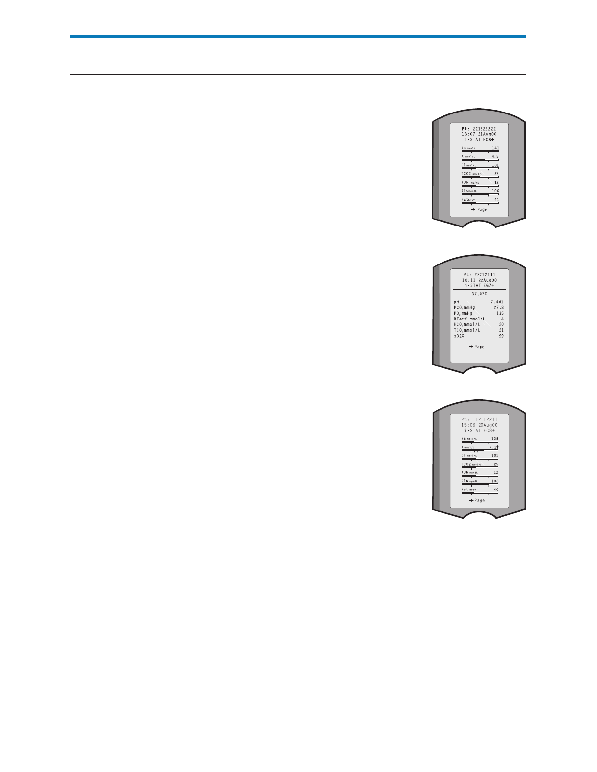
interPretation of disPlayed results
Results Display
Reportable Ranges
Reference Ranges
Test results are displayed with numerical concentration values in the units
selected for the Customization profile. For patient test
results, bar graphs depicting the values in relation to
reference ranges are also displayed. Reference ranges are
marked on the bars by tic marks. When all test values
are within their reference ranges, the tic marks will
be centrally aligned. The bar graphs can be used as a
visual cue for distinguishing between “normal” and
“abnormal” results. Blood gas, coagulation, and cTnI
results are not displayed with bar graphs and reference
ranges.
If a value exceeds the reference range, the bar graph
may be rescaled to show the reference range and value
in relation to the measurement range.
The reportable range (sometimes referred to as the
linear range) is the concentration range over which test
results are valid. Reportable ranges programmed into
the analyzer can are listed in the Cartridge and Test
Information section.
Reference ranges (sometimes referred to as normal
ranges) in the default Customization profile are
derived from the literature and are listed in the
Cartridge and Test Information section as well as in
the Customization option on the analyzer. Variables
such as sex, age, heritage and other demographic
factors of a population may cause a shift in these
ranges. Therefore, it is usually recommended
that each facility determine its own reference
ranges. Reference ranges can be changed using the
Customization function on the Central Data Station.
Action Ranges
Action ranges (sometimes referred to as critical values)
indicate results that require immediate attention. When
a test result falls outside the action range it is flagged as
either above the high action range or below the low
action range . Action ranges are programmed into
the analyzer using the Customization function on the Central Data Station and
can be viewed on the analyzer under the Customization option.
Note: Since the and symbols cannot be printed from the Martel Printer,
action range flags on a Martel printer will appear with the << >> symbol.
Art: 714374-01E Rev. Date: 03/03/08 12-7
Page 96

Flags
When the analyzer detects an out-of-range result or an uncharacteristic sensor
signal, the condition is indicated by a flag. See table below for flags and symbols
used with results. Note: The reportable range flags do not apply when testing
is performed under Quality Tests Option 3 – Cal Ver. Action flags do not apply
to Option 1 – Control or Option 3 – Cal Ver.
Display Action
>
The result falls above the reportable
range of the test.
<
The result falls below the low end of the
reportable range of the test.
< >
The result is dependent on another test
that has been flagged.
The < > flag will also be displayed for
TCO2, pH, PCO2, HCO3, anion gap,
base excess and sO2 if the TCO2 is
outside the reportable range. Because
the values outside the reportable range of
TCO2 are essentially non-physiological,
the TCO2 range check is used as an
additional quality check on the validity of
the underlying pH and PCO2 results.
***
The result is above the high action range. If the action ranges for potassium are 3.2
The result is below the low action range. If the action ranges for potassium are 3.2
The signals from a particular sensor
are uncharacteristic. Uncharacteristic
signals can be caused by a compromised
sensor or by an interferent in the sample.
This flag also appears for any test
dependent on another test which is
flagged with stars.
Analyzer Response /
Comments
If an ACT result is displayed as >1000,
the result should be reported as “greater
than 1000 seconds.”
If a pH result is displayed as <6.5, the
result should be reported as “less than
6.5.”
If a sodium result is displayed as >180,
the calculations for potassium, chloride,
BUN/Urea and hematocrit, which depend
upon the sodium measurement, will be
flagged < >.
and 5.5, a result of 6.0 will be displayed
as 6.0 .
and 5.5, a result of 3.0 will be displayed
as 3.0 .
The sample should be retested using
another cartridge.
If the stars reappear, refer to the
troubleshooting paragraph in this section
of the manual.
12-8 Art: 714374-01E Rev. Date: 03/03/08
Page 97

troubleshooting
Warning Message
Message and
Quality Check Code
*** Instead of Results
If testing is disabled due to warning message, the condition must be corrected
and the analyzer must be turned off and back on again before testing is
enabled.
See Troubleshooting section
Stars appear in place of results if the analyzer detects that the sensor’s signal is
uncharacteristic. Since the sensor check is part of the i-STAT quality system,
an occassional result will be flagged due to a bad sensor. Other causes of this
flag are improperly stored cartridges or an interfering substance in the patients
sample, either extrinsic, such as the wrong anticoagulant, or intrinsic such as
medication. Also, aged samples may contain products of metabolism that can
interfere with the tests.
• Check the supply of cartridges in use with a control solution.
• If the control is in range, draw a fresh sample from the patient and
retest.
• If the stars appear in place of results again, there may be an
interfering substance. Refer to the Cartridge and Test Information
section for a list of interfering substances. Test the sample using
another method.
• If the control is out-of-range or if stars are displayed in place of
results, there may be a problem with the cartridge lot number. Use
another lot number or repeat the test using another method, and
contact your support representative. (Refer to Support Services
information in the Troubleshooting section.)
Unexpected Results
When results do not reflect the patient’s condition, repeat the test using a fresh
cartridge and sample. If results are still suspect, test the lot of cartridges in use
with i-STAT control solutions. If the controls are in range, there may be an
interfering substance in the sample. Check the Cartridge and Test Information
sheets for the test in question. Test by another method to verify the result.
If the controls are out of range there may be a problem with the cartridge lot
number. Use another lot number or repeat the test using another method, and
contact your support representative. (Refer to Support Services information in
the Troubleshooting section.)
Art: 714374-01E Rev. Date: 03/03/08 12-9
Page 98

Page 99

PROCEDURES FOR GLUCOSE TEST STRIP TESTING
13
Operating Guidelines
for All Samples
Follow the recommended guidelines to obtain the most accurate results.
• Use the test strips before their expiration date.
• Do not use test strips that are wet, bent, scratched or damaged.
• Use the test strip immediately after opening its foil packet.
• Do not scan a packet’s barcode and use a test strip from another packet.
This may cause incorrect assay results to be generated.
• Cover the entire target area of the test strip with the blood sample. The
test results will not be affected if the target area has been briefly touched
with the patient’s finger, a syringe, a capillary tube or pipette.
• If the test fails to start, apply a second drop of blood to the target area
within 30 seconds. If the test fails to start after the second drop is
applied, or if more than 30 seconds have passed, discard the used test
strip and repeat the test.
• After the blood is applied to the test strip and the test starts, do not touch
the strip.
• Use a new test strip when repeating a patient test.
• Refer to the package insert in the test strip box for specific directions on
storage and use of the test strips.
• Store analyzers in use near the testing location or in an area close to
the same temperature as the testing area. Do not store analyzers near
equipment that gives off heat or in the direct sunlight. If an analyzer is
moved to a testing area that is slighly cooler or warmer (5 °C or 9 °F) than
the previous testing or storage area, allow 30 minutes for the analyzer to
equilibrate to the temperature of the new testing area before using the
analyzer. If the temperature difference is substantial allow 90 minutes
for equilibration.
• i-STAT 1 Analyzers may require a modification to the glucose strip port in
order to be compatible with Precision PCx Plus Glucose Test Strips. This
modification can be identified by noting the analyzer serial number and
by inspecting the glucose strip port.
Analyzer
Serial
Number
≥ 317900 No No
< 317900 Yes No
< 317900 No Yes. Contact your Support Services
Art: 714375-01C Rev. Date: 08/23/06
Blue Strip
Port Spacer
Present?
Strip Port Modification Needed?
representative for information on modifying
the port. The modification is easily self-
installed.
Page 100

Performing Patient glucose assay with test striP
Procedure
Caution
Blank or active. Press the On/Off key to turn the
Test Menu
1 – Last Results
2 – i-STAT Cartridge
3 – PCx Glucose Strip
Precision PCx Blood Glucose
Strip
1 – Patient
2 - Control
Scan or Enter Operator ID Press Scan to scan the Operator
Scan or Enter Patient ID
If the analyzer displays a message not indicated in this procedure, refer to the
Troubleshooting section of this manual.
Never look into the barcode scanner beam or point it toward anyone’s eyes.
The beam could cause permanent eye damage.
Display Action Analyzer Response
Logo briefly displayed followed by Test
analyzer on.
Menu.
If the analyzer is on, press the
Menu key to return to the Test
Menu or turn the analyzer off and
back on.
Press 3 to select PCx Glucose Strip. REMOVE STRIP will be displayed if a strip
is inserted before the analyzer displays
INSERT STRIP.
Press 1 to select Patient.
Possible message: “Control Required
Patient Testing Disabled”
If enabled, the analyzer will validate the
ID or manually enter the Operator ID
using the keypad and press Enter.
Press Scan to scan the Patient ID,
or manually enter the Patient ID
using the keypad and press Enter.
ID. If enabled, the analyzer will prompt for
the ID to be repeated.
If enabled, the analyzer will validate the
ID. If enabled, the analyzer will prompt
for the ID to be repeated. If enabled, the
most recent patient ID can be recalled by
pressing the key.
13-2
Scan or Enter Strip Lot Number Press Scan to scan the Strip Lot
Number, or manually enter the Strip
Lot Number using the keypad and
press Enter.
(see Note below)
Art: 714375-01C Rev. Date: 08/23/06
Possible messages: “Lot Expired, “
“Invalid Number, “ “Invalid Length, “ “Strip
Lot xxx Is Not in List”
 Loading...