


1116554, 1116663
US User Manual
1116752 Rev. A 2018/09
Dear Customer,
Congratulations on the purchase of your Afinion™ 2 Analyzer.
Upon arrival of your Afinion 2 Analyzer we recommend that the serial number along with the software version be recorded in the table provided below. The additional rows in the table are to be utilized if a software upgrade is performed on your Afinion 2 Analyzer. The recorded information will be of great value if and when a question is reported, or the desire to add a new Afinion Test to your analyzer arises.
Serial number
(for serial number (SN), see label on the rear side of the analyzer or on the transport container)
Software records
Date |
Software version* |
Afinion™ Tests available |
Upon receipt
1.SW upgrade
2.SW upgrade
3.SW upgrade
4.SW upgrade
5.SW upgrade
*See start-up menu when you power on the analyzer (see “How to power on the analyzer”, page 11).
Notes
_________________________________________________________________________________________________________________________________________________
_________________________________________________________________________________________________________________________________________________
Technical Support
Call 1.866.216.9505
2 | US |
AFINION™ 2 User Manual |

Intended use of the AFINION™ 2 System
Afinion 2 System, consisting of the Afinion 2 Analyzer and the Afinion Test Cartridges, is for in vitro diagnostic use only. Afinion 2 Analyzer is a compact multi-assay analyzer for point-of-care testing and is designed to analyze the Afinion Test Cartridges.
CLIA Statements - Waived Afinion™ Tests
Afinion HbA1c is waived under the Clinical Laboratory Improvement Amendment of 1988 (CLIA`88). A CLIA Certificate of Waiver is needed to perform testing in a waived setting.
If the laboratory does not have a Certificate of Waiver, the Application for Certification (Form CMS-116), can be obtained at https://www.cms.gov/cmsforms/downloads/cms116.pdf.
The form should be mailed to the address of the local State Agency of the State in which the laboratory resides (https://www.cms.gov/CLIA/12_State_Agency_&_Regional_Office_CLIA_Contacts.asp).
If the laboratory modifies the Afinion Test or Afinion 2 Analyzer system instructions, the test no longer meets the requirements for waived categorization. A modified test is considered to be highly complex and is subject to all applicable CLIA requirements.
Conformity to directives and standards
European IVD directive and RoHS 2 directive (CE marking)
The Afinion 2 Analyzer meets all provisions in the Directive 98/79/EC on in vitro diagnostic (IVD) medical devices and in the Directive 2011/65/EU on the restriction of the use of certain hazardous substances in electrical and electronic equipment (RoHS 2).
North American product safety standards (CNUS mark)
The Afinion 2 Analyzer has been tested and found to be in conformity with North American safety standards. See list of safety standards below.
Safety standards
The Afinion 2 Analyzer has been tested and found to be in conformity with standards for Safety requirements for electrical equipment for measurement, control, and laboratory use (IEC 61010-1:2010 , UL 61010-1:2012, CAN/CSA-C22.2: 61010-1 -12) and standard for Particular requirements for in vitro diagnostic (IVD) medical equipment (IEC 61010-2-101:2015).
EMC standards
The Afinion 2 Analyzer has been tested and found to be in conformity with standards for Electrical equipment for measurement, control, and laboratory use
– EMC requirements (EN 61326-1:2013, EN 61326-2-6:2006, EN 61326-2-6:2013 and CFR 47 Telecommunications, Chapter I- FCC Part 15 – Radio Frequency Devices – Subpart B: unintentional radiators).
AFINION™ 2 User Manual |
US | 3 |

4 | US |
AFINION™ 2 User Manual |
|
|
Table of Contents |
Table of contents |
|
|
|
|
|
Introduction |
About this user manual |
7 |
|
|
|
|
Examining the package contents |
7 |
|
|
|
Analyzer System Description |
Description of the AFINION™ 2 Analyzer |
8 |
|
|
|
|
Description of the Afinion™ Test Cartridge |
8 |
|
How the AFINION™ 2 System works |
9 |
|
|
|
|
Internal process control |
9 |
|
|
|
|
The analyzer self-test |
9 |
|
|
|
|
The fail-safe mechanisms |
9 |
|
|
|
|
External process control |
9 |
|
|
|
|
Patients ID |
9 |
|
|
|
|
Operator ID |
9 |
|
|
|
|
Quality Control lockout |
9 |
|
|
|
|
Calibration |
9 |
|
|
|
Getting Started |
Installing your analyzer |
10 |
|
|
|
|
Connecting power supply |
10 |
|
|
|
|
Connecting additional equipment |
10 |
|
|
|
|
Connectivity |
10 |
|
|
|
|
How to power ON the analyzer |
11 |
|
|
|
|
How to power OFF the analyzer |
11 |
|
|
|
|
How to operate the analyzer |
11 |
|
|
|
Configuration |
The AFINION™ 2 menus |
12 |
|
|
|
|
Setting the configuration |
13 |
|
|
|
|
Patient ID configuration |
13 |
|
|
|
|
Patient ID enable/disable |
13 |
|
|
|
|
Operator configuration |
14 |
|
|
|
|
Operator ID enable/disable |
14 |
|
|
|
|
Operator login expiration |
14 |
|
|
|
|
Operator list management |
14 |
|
|
|
|
Choosing language |
15 |
|
|
|
|
Adjusting screen/beeper settings |
15 |
|
|
|
|
Setting date and time |
15 |
|
|
|
|
QC lockout configuration |
16 |
|
|
|
|
General settings |
17 |
|
|
|
|
Erase all contents and configuration |
17 |
|
|
|
|
Analyzer network settings |
17 |
|
|
|
|
Connectivity settings |
18 |
|
|
|
Quality Control |
Why quality control testing? |
19 |
|
|
|
|
Choosing control material |
19 |
|
|
|
|
Handling and testing controls |
19 |
|
|
|
|
Frequency of control testing |
19 |
Table of contents continues on next page
AFINION™ 2 User Manual |
US | 5 |

Table of Contents
Testing Procedures |
Operating precautions |
20 |
|
|
|
|
When operating the analyzer |
20 |
|
|
|
|
When handling the test cartridge |
20 |
|
|
|
|
Preparing for an AFINION™ 2 Analysis |
20 |
|
|
|
|
Collecting a sample |
21 |
|
|
|
|
Analysing a patient/control sample |
21 |
|
|
|
|
Using the operator ID function |
22 |
|
|
|
|
Entering operator ID |
22 |
|
|
|
|
Using the patient ID function |
22 |
|
|
|
|
Entering patient ID |
22 |
|
|
|
|
Using the control ID function |
23 |
|
|
|
|
Entering control ID |
23 |
|
|
|
|
Using the QC lockout function |
23 |
|
|
|
|
QC lockout status |
23 |
|
|
|
|
Running controls with enabled QC lockout function |
24 |
|
|
|
|
Patient and control results records |
25 |
|
|
|
|
View, print and export patient and control results |
25 |
|
|
|
Information Codes and |
When an information code appears |
26 |
Troubleshooting |
Information codes caused by test-specific limitations |
26 |
|
|
|
|
Information codes caused by sample or test cartridge |
27 |
|
|
|
|
Information codes and messages caused by analyzer failure |
27 |
|
|
|
|
Other information codes |
28 |
|
|
|
|
Service information |
28 |
|
|
|
Maintenance |
Cleaning and maintenance |
29 |
|
|
|
|
Cleaning the exterior |
29 |
|
|
|
|
Cleaning the cartridge chamber |
29 |
|
|
|
|
Disposal of the analyzer |
29 |
|
|
|
|
Software upgrade |
29 |
|
|
|
Warranty |
|
30 |
|
|
|
Technical Specifications |
AFINION™ 2 Analyzer |
31 |
|
|
|
|
Additional equipment |
31 |
|
|
|
Gallery of Icons |
The touch buttons and their function |
32 |
|
|
|
|
Other symbols and signs |
34 |
|
|
|
Symbols and Abbrevations |
|
35 |
|
|
|
6 | US |
AFINION™ 2 User Manual |

Introduction
About this user manual
This user manual will guide you through installation, operation and maintenance of your Afinion 2 Analyzer. The user manual also explains how the analyzer works, describes the quality assurance system and assists you in troubleshooting.
For analysing patient samples or controls, please also read the test specific information given in the package inserts following the Afinion Test Kits. The quick reference guides, available from your local Afinion supplier, highlight the main steps of the test procedures.
It is recommended that you become familiar with these user instructions before you start operating the Afinion 2 Analyzer.
Some of the information in this user manual is accompanied with a symbol that points you to the following particulars:
Warnings and precautions
References to the package inserts for the specific Afinion Tests and control kits
Examining the package contents
When unpacking, check the contents against the list below and examine the components for signs of shipping damage.
The Afinion 2 package unit includes:
•Afinion 2 Analyzer
•Power cable
•Power supply, 24 VDC
•User manual
•Quick guides for the available Afinion Tests
If the package unit is found incomplete, please report missing items or shipping damage to your supplier. It is recommended to keep the shipping box in case of later transportation of the analyzer.
AFINION™ 2 User Manual |
US | 7 |
Analyzer System Description
Description of the AFINION™ 2 Analyzer
Figure 1 shows the main exterior parts of the Afinion 2 Analyzer.
1
2
3
4
5
Figure 1
1 |
ON/OFF button: |
Turns the power to the analyzer on and off. |
2 |
Red and green LEDs: |
Light emitting diodes (LEDs) that indicates whether the analyzer is busy or not. |
3 |
Touch screen: |
Allows you to communicate with the analyzer through touch buttons and messages. |
4 |
The lid: |
Covers and protects the cartridge chamber. |
5 |
Connectors: |
For connecting to mains power supply. Options for printer, barcode reader and/or LIS/HIS/EMR. |
Do not open the lid manually.
Description of the Afinion™ Test Cartridge
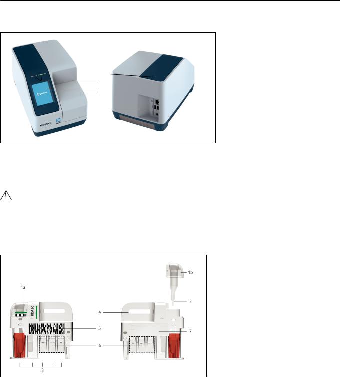
The Afinion Test Cartridge is unique for each analyte to be measured, as the reagent composition, reagent volumes and the integrated devices are test specific. The test cartridge label has a colour unique for the test. The test cartridges are separately packed in foil pouches to protect the reagents and plastic devices from light, dirt and humidity. A single test cartridge contains all necessary reagents for one test and is ready to use. An integrated sampling device is used for collection of the patient sample or control. The test cartridge cannot be reused. Figure 2 illustrates an Afinion Test Cartridge with its functional parts:
Left side |
Right side |
Figure 2
1 |
Sampling device: |
For collection of patient sample or control (1a - closed position, 1b - lifted position). |
2 |
Capillary: |
Capillary to be filled with sample material. |
3 |
Reaction wells: |
Contain all necessary reagents for one test. |
4 |
Handle: |
For correct finger grip. |
5 |
Barcode label: |
Contains assay and lot-specific information for the analyzer. |
6 |
Optical reading area: |
Area for transmission measurement. |
7 |
ID area: |
Space for written or labelled sample identification. |
8 | US |
AFINION™ 2 User Manual |

Analyzer System Description
How the AFINION™ 2 System works
The Afinion 2 System uses different chemical and mechanical assay methods combined with advanced, computerized processing and measuring technology.
A test cartridge with patient sample or control is placed in the cartridge chamber of the analyzer. By manually closing the lid, the test cartridge is transported into the analysis compartment of the analyzer. Test and lot-specific information is obtained from the barcode label (Figure 2). When the test cartridge enters the
analyzer, the integrated camera reads the barcode which then initiates the processing of the test cartridge. The sample and reagents are automatically transferred between the wells. An internal camera monitors the entire process. Light-emitting diodes (LEDs) illuminate the reaction area, which can be either a coloured membrane or a reaction well. The camera detects the reflected or transmitted light, which is converted to a test result and displayed on the touch screen. When the user accepts the result, the lid covering the cartridge chamber opens automatically and the used test cartridge can be removed and discarded. The analyzer is then ready for the next run.
Internal process control
The analyzer self-test
A self-test is performed during start-up of the analyzer to ensure that the instrument is operating according to established specifications. The self-test validates:
•Hardware and software integrity
•Test cartridge transport system
•Liquid transport system
•Camera vision system
If the self-test fails at any point, the red LED will start flashing and an information code will be displayed on the touch screen (see “Information codes and troubleshooting”, page 26-28).
When the analyzer is powered on for a longer period, it will automatically restart once a day to ensure that a self-test is done regularly. This procedure does not interrupt any analysis of the test cartridge.
The fail-safe mechanisms
Fail-safe mechanisms are included to secure safe processing. The integrated camera inspects the test cartridges initially before the process starts and during the assay. If defects are detected (e.g. broken capillary, the cartridge is used past its expiry date), the test cartridge is rejected and an information code is displayed. During processing vital functions and components (e.g. pumps, heater) are supervised. When problems are detected by the built-in safety mechanism, the process will be aborted and an information code will be displayed.
External process control
Patient ID
The Afinion 2 patient ID functionality will, if configured, allow up to four patient ID fields to be entered. The patient ID will be stored with each patient test result in the result records.
Operator ID
The Afinion 2 operator functionality will, if configured, require the operators to login before testing. The functionality may also prevent unauthorized operators to login, perform tests and configuration. The operator ID will be stored with each test result in the result records.
Quality Control lockout
The Afinion 2 QC lockout function allows you to configure the instrument to automatically enforce your local required frequency of control testing. If the required control test has not been performed or the control result is outside the acceptable range, the instrument will disable patient testing for this assay. For manufacturer recommendations (see “Frequency of control testing” page 19).
For more information regarding these functionalities, see “Configuration” page 12–18.
Calibration
The Afinion 2 Analyzer has been manufactured to deliver reliable and accurate results. During manufacturing, the analyzers are calibrated against a reference system. This procedure has been established to ensure that all analyzers operate within identical tolerance limits.
Test specific calibration data are established for each lot of test cartridges and then stored in the barcode label (Figure 2). When the test cartridge enters the analyzer, the integrated camera reads the barcode. The calibration data for the actual lot are transferred to the instrument and used for calculating the results. Calibration by the operator is thus not required.
AFINION™ 2 User Manual |
US | 9 |
Getting Started
Installing your analyzer
Place your Afinion 2 Analyzer on a dry, clean, stable and horizontal surface. Make sure that the analyzer is located with sufficient surrounding airspace, at least 5 inches on each side. Placement of Afinion 2 Analyzer should allow easy disconnection from the wall outlet at any time. Acclimate the analyzer to ambient operating temperature (15-32°C, 59-89°F) before use.
The analyzer might be impaired by: |
|
• Condensing humidity and water |
• Vibrations (e.g. from centrifuges and dishwashers) |
• Heat and large temperature variations |
• Electromagnetic radiation |
• Direct sunlight |
• Movement of the analyzer during processing of a test cartridge |
Connecting power supply
-Connect the power cable to the power supply.
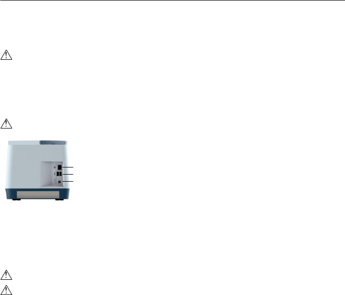
-Insert the plug from the power supply into the power socket (Figure 3) in the back of the analyzer.
-Plug in the power supply to a wall outlet.
Only use the power supply and cable supplied with Afinion 2 Analyzer. Any other power supplies or cables can damage the analyzer and may cause possible hazards.
Figure 3
11 Ethernet port for connection to LIS/HIS/EMR systems. Use shielded cable.
22 USB-A connectors for printer, USB flash and barcode reader.
33 Power input for power supply connection
Connecting additional equipment
Optional equipment, not provided with your Afinion 2 Analyzer are:
•External barcode reader – for reading barcoded sample or operator identification.
•Printer – for optional print out of test results.
For additional information regarding barcode reader and printer specifications, please contact your local Afinion 2 supplier.
Connecting the equipment should be done while the analyzer is powered off.
All equipment connected to the USB and/or Ethernet ports must have double or reinforced insulation from mains to prevent the risk of electric shock.
Connectivity
Afinion 2 Analyzer can reliably transfer test information to an information system. Use the Ethernet cable to interface the Afinion 2 Analyzer to an information system. Afinion 2 Analyzer automatically transfers patient and control results to a connected LIS/HIS/EMR system via TCP/IP networking using the protocols POCT1-A, HL7, ASTM 1381-85 (low level) or ASTM 1394-97 (high level), selectable by configuration. ASTM and HL7 protocols support the transfer of patient and QC results. POCT1-A protocol supports in addition functions such as device lockout and operator list management. Operator configuration allows for protection of connectivity settings. When operator configuration is set to operator ID with verification, the configuration of connectivity will only be available for operators at supervisor level. For relevant information, see chapter “Operator configuration”, page 14.
When you export data that contains patient information, it is your responsibility to comply with your local regulations on protection of personal health information.
Afinion 2 Analyzer POCT1-A, ASTM and HL7 communication protocols are available at www.alere.com or by contacting your local Afinion 2 supplier.
10 | US |
AFINION™ 2 User Manual |
Getting Started
How to power ON the analyzer 1
2
3
How to power OFF the analyzer
Switch off the analyzer by pressing the ON/OFF button (Figure 1). The analyzer should be powered off after the end of a working day.
The analyzer can only be powered off when the cartridge chamber is empty and the lid is closed. If the ON/OFF button is pressed and the lid is open, the message ”Close lid” will appear on the screen.
How to operate the analyzer
The Afinion 2 Analyzer has two main user interfaces, the touch screen and the cartridge chamber. The analyzer is easily operated using the touch buttons that appear on the screen. When a button is touched, its function will be activated. Text messages that appear on the screen will help guide you through the testing procedure. The functions of the touch buttons are explained in the section “Gallery of icons”, page 32–34.
The other main operative part of the Afinion 2 Analyzer is the cartridge chamber. The cartridge chamber is designed to receive the test cartridge in one orientation only. The lid must be manually closed, but opens automatically. When a new test cartridge is placed in the chamber, manually closing the lid will initiate the analysis. When the analysis is complete the lid will open automatically. The lid protects the cartridge chamber from dust, dirt, light and humidity during processing and when the analyzer is not in use.
• The lid must be manually closed, but opens automatically. Do not open the lid manually.
• Use the fingertips only on the touch screen. Do not use pens or other sharp instruments.
1
2
Figure 4
1 Text message
32 Touch buttons
3 The cartridge chamber with a test cartridge
44 The lid in open position
Screen saver
The screen saver will turn on after 3 minutes, if the touch screen is not in use. To reactivate, touch the screen.
Light signals (the red and green LEDs)
The red diode is illuminated when the analyzer is busy. A flashing red light is seen when an information code is displayed. The green diode is illuminated when the analyzer is ready for use. A flashing green light indicates completion of an analysis.
Sound signals
A short beep indicates completion of an analysis. Two beeps mean that an information code or message is displayed.
AFINION™ 2 User Manual |
US | 11 |
 Loading...