

Page 1

Left Ventricular Assist System
Instructions for Use
Page 2

Page 3

Abbott
HEARTMATE 3™ LEFT VENTRICULAR ASSIST SYSTEM
Instructions for Use
Page 4

Page 5

™ Indicates a trademark of the Abbott group of companies.
‡ Indicates a third party trademark, which is property of its respective owner.
Pat. http://www.abbott.com/patents
© 2020 Abbott. All Rights Reserved.
Bluetooth and Bluetooth logo are registered trademarks of Bluetooth SIG, Inc.
iii
Page 6

Preface - - - - - - - - - - - - - - - - - - - - - - - - - - ix
1 Introduction - - - - - - - - - - - - - - - - - - - - 1-1
Understanding Warnings and Cautions - - - - - - - - - - - - - - - - - - - - - - - 1-2
Overview - - - - - - - - - - - - - - - - - - - - - - - - - - - - - - - - - - - - - - - 1-3
Indications - - - - - - - - - - - - - - - - - - - - - - - - - - - - - - - - - - - - - - 1-7
Contraindications - - - - - - - - - - - - - - - - - - - - - - - - - - - - - - - - - - - 1-7
Adverse Events - - - - - - - - - - - - - - - - - - - - - - - - - - - - - - - - - - - - 1-8
Pre-Use Requirements - - - - - - - - - - - - - - - - - - - - - - - - - - - - - - - - - 1-8
Equipment Overview - - - - - - - - - - - - - - - - - - - - - - - - - - - - - - - - - 1-10
Required, Backup, and Optional Components and Equipment - - - - - - - - - - - - 1-15
Principles of Operation - - - - - - - - - - - - - - - - - - - - - - - - - - - - - - - - 1-17
Explanation of Parameters - - - - - - - - - - - - - - - - - - - - - - - - - - - - - - 1-19
2 System Operations - - - - - - - - - - - - - - - - - 2-1
HeartMate 3™ Left Ventricular Assist Device Overview- - - - - - - - - - - - - - - - 2-2
System Controller Overview- - - - - - - - - - - - - - - - - - - - - - - - - - - - - - 2-8
The Backup System Controller- - - - - - - - - - - - - - - - - - - - - - - - - - - - - 2-45
3 Powering the System - - - - - - - - - - - - - - - - 3-1
Power Overview - - - - - - - - - - - - - - - - - - - - - - - - - - - - - - - - - - - 3-2
Using the Power Module - - - - - - - - - - - - - - - - - - - - - - - - - - - - - - - 3-4
Using the Mobile Power Unit - - - - - - - - - - - - - - - - - - - - - - - - - - - - - 3-34
Using HeartMate 14 Volt Lithium-Ion Batteries - - - - - - - - - - - - - - - - - - - - 3-51
Switching Power Sources - - - - - - - - - - - - - - - - - - - - - - - - - - - - - - - 3-66
Battery Charger Overview - - - - - - - - - - - - - - - - - - - - - - - - - - - - - - 3-73
Charging HeartMate Batteries - - - - - - - - - - - - - - - - - - - - - - - - - - - - 3-80
Calibrating HeartMate Batteries - - - - - - - - - - - - - - - - - - - - - - - - - - - 3-84
Using the Charger to Check Battery Power - - - - - - - - - - - - - - - - - - - - - - 3-86
Care and Maintenance of the Battery Charger - - - - - - - - - - - - - - - - - - - - 3-87
4 HeartMate Touch™ Communication System - - - - - 4-1
Overview - - - - - - - - - - - - - - - - - - - - - - - - - - - - - - - - - - - - - - - 4-2
Set Up the HeartMate Touch™ Communication System- - - - - - - - - - - - - - - - 4-7
Connect the HeartMate Touch™ Wireless Adapter to the
iv
Page 7

HeartMate Touch Communication System - - - - - - - - - - - - - - - - - - - - - - 4-11
Interface Overview - - - - - - - - - - - - - - - - - - - - - - - - - - - - - - - - - - 4-20
HeartMate Touch™ App Views - - - - - - - - - - - - - - - - - - - - - - - - - - - - 4-21
Settings Panel - - - - - - - - - - - - - - - - - - - - - - - - - - - - - - - - - - - - - 4-23
Alarms - - - - - - - - - - - - - - - - - - - - - - - - - - - - - - - - - - - - - - - - 4-40
Pump Parameters - - - - - - - - - - - - - - - - - - - - - - - - - - - - - - - - - - - 4-50
Monitor View - - - - - - - - - - - - - - - - - - - - - - - - - - - - - - - - - - - - - 4-55
Clinical View - - - - - - - - - - - - - - - - - - - - - - - - - - - - - - - - - - - - - 4-56
Historical View - - - - - - - - - - - - - - - - - - - - - - - - - - - - - - - - - - - - 4-62
5 Surgical Procedures - - - - - - - - - - - - - - - - 5-1
Surgical Considerations- - - - - - - - - - - - - - - - - - - - - - - - - - - - - - - - 5-2
Equipment and Supplies Required for Implant - - - - - - - - - - - - - - - - - - - - 5-4
Preimplant Procedures- - - - - - - - - - - - - - - - - - - - - - - - - - - - - - - - - 5-7
Unpacking - - - - - - - - - - - - - - - - - - - - - - - - - - - - - - - - - - - - - - 5-10
Unpacking the Pump and Accessories Tray - - - - - - - - - - - - - - - - - - - - - - 5-12
Unpacking the Sealed Outflow Graft - - - - - - - - - - - - - - - - - - - - - - - - - 5-16
Preparing the Sealed Outflow Graft - - - - - - - - - - - - - - - - - - - - - - - - - 5-17
Unpacking the System Controller - - - - - - - - - - - - - - - - - - - - - - - - - - - 5-18
Unpacking the Modular Cable - - - - - - - - - - - - - - - - - - - - - - - - - - - - 5-19
Connecting and Initializing the Sterile System Controller to Non-Sterile Equipment - 5-22
Preparing, Running, and Priming the Pump - - - - - - - - - - - - - - - - - - - - - - 5-25
Preparing the Coring Knife - - - - - - - - - - - - - - - - - - - - - - - - - - - - - - 5-34
Implant Procedures - - - - - - - - - - - - - - - - - - - - - - - - - - - - - - - - - - 5-35
Postimplant Procedures - - - - - - - - - - - - - - - - - - - - - - - - - - - - - - - - 5-60
Postimplant Considerations - - - - - - - - - - - - - - - - - - - - - - - - - - - - - - 5-66
Device Explant - - - - - - - - - - - - - - - - - - - - - - - - - - - - - - - - - - - - 5-70
6 Patient Care and Management - - - - - - - - - - - 6-1
Postoperative Patient Care - - - - - - - - - - - - - - - - - - - - - - - - - - - - - - 6-2
Ongoing Patient Assessment and Care - - - - - - - - - - - - - - - - - - - - - - - - 6-6
Important Clinical Considerations for HeartMate 3™ Patients - - - - - - - - - - - - 6-9
Using the Shower Bag - - - - - - - - - - - - - - - - - - - - - - - - - - - - - - - - 6-13
Wearing and Carrying System Components - - - - - - - - - - - - - - - - - - - - - 6-26
Preparing for Sleep - - - - - - - - - - - - - - - - - - - - - - - - - - - - - - - - - - 6-63
Ongoing System Assessment and Care - - - - - - - - - - - - - - - - - - - - - - - - 6-64
Educating and Training Patients, Families, and Caregivers- - - - - - - - - - - - - - 6-67
v
Page 8

7 Alarms and Troubleshooting - - - - - - - - - - - - 7-1
System Controller Alarms - - - - - - - - - - - - - - - - - - - - - - - - - - - - - - - 7-2
HeartMate Touch™ App Alarms - - - - - - - - - - - - - - - - - - - - - - - - - - - 7-25
Handling Power Module Alarms - - - - - - - - - - - - - - - - - - - - - - - - - - - 7-37
Mobile Power Unit Alarms - - - - - - - - - - - - - - - - - - - - - - - - - - - - - - 7-40
Using the Charger to Check Battery or Charger Status - - - - - - - - - - - - - - - - 7-42
Guidelines for Power Cable Connectors - - - - - - - - - - - - - - - - - - - - - - - 7-45
What Not To Do: Driveline and Cables- - - - - - - - - - - - - - - - - - - - - - - - 7-46
8 Equipment Storage and Care - - - - - - - - - - - - 8-1
Storage and Transport - - - - - - - - - - - - - - - - - - - - - - - - - - - - - - - - 8-2
Cleaning and Maintenance - - - - - - - - - - - - - - - - - - - - - - - - - - - - - - 8-4
Product Disposal - - - - - - - - - - - - - - - - - - - - - - - - - - - - - - - - - - - 8-11
A Summary of the Clinical Study - - - - - - - - - - - A-1
Pediatric Real-World Data - - - - - - - - - - - - - - - - - - - - - - - - - - - - - - A-62
B Technical Specifications - - - - - - - - - - - - - - B-1
C Safety Testing and Classification - - - - - - - - - - C-1
D HeartMate 3™ Product List - - - - - - - - - - - - - D-1
E Symbols - - - - - - - - - - - - - - - - - - - - - - E-1
F Safety Checklists - - - - - - - - - - - - - - - - - - F-1
G Glossary - - - - - - - - - - - - - - - - - - - - - G-1
Index- - - - - - - - - - - - - - -
- -
- - - - - - - Index-1
vi
Page 9

Preface
This manual contains information needed to properly and safely operate the HeartMate 3™ Left
Ventricular Assist System. Users of the HeartMate 3 Left Ventricular Assist System should have a
practical knowledge of the principles of mechanical circulatory support and should be aware of the
physiological and psychological needs of a patient undergoing mechanical ventricular support. New
users should read this document in its entirety, before system operation. For experienced
practitioners, this manual may serve as a reference.
As with all prescription medical devices, clinical procedures should be conducted under the direction
of the prescribing physician. The professional staff at Abbott regularly provides laboratory training
and on-site, in-service programs.
ix
Page 10

INTRODUCTION
This section provides an introduction to the HeartMate 3™ Left Ventricular Assist System.
Understanding Warnings and Cautions - - - - - - - - - - - - - - 1-2
1
Overview - - - - - - - - - - - - - - - - - - - - - - - - - - - - - - 1-3
Indications - - - - - - - - - - - - - - - - - - - - - - - - - - - - - 1-7
Contraindications - - - - - - - - - - - - - - - - - - - - - - - - - - 1-7
Adverse Events - - - - - - - - - - - - - - - - - - - - - - - - - - - 1-8
Pre-Use Requirements - - - - - - - - - - - - - - - - - - - - - - - - 1-8
Equipment Overview - - - - - - - - - - - - - - - - - - - - - - - - 1-10
Required, Backup, and Optional Components and Equipment - - - 1-15
Principles of Operation - - - - - - - - - - - - - - - - - - - - - - - 1-17
Explanation of Parameters - - - - - - - - - - - - - - - - - - - - - 1-19
1-1
Page 11

Chapter 1 Introduction
Understanding Warnings and Cautions
Warnings refer to actions or hazardous conditions that could cause serious injury or death if not
avoided. Ignoring a warning can cause sudden and serious injury, life-threatening harm, or death for
the user or patient.
Cautions refer to actions or potentially unsafe conditions that may cause injury, damage the
equipment, or affect how the system works. Ignoring a caution can cause patient or user injury, or
result in equipment failure or sub-optimal system operation. Although important for maximum safety
and optimal system function, usually cautions do not refer to life-threatening risks.
In this manual, warnings and cautions that are relevant to a specific procedure or piece of equipment
appear at the start of each applicable section.
WARNING !
Warnings appear in the manual in this format.
CAUTION !
Cautions appear in the manual in this format.
1-2
Page 12

Chapter 1 Introduction
Overview
The HeartMate 3™ Left Ventricular Assist System (LVAS) is a set of equipment and materials that
together comprise a medical device designed to provide therapeutic benefit to those affected with
advanced heart failure. In service, the LVAS assumes some or all of the workload of the left ventricle,
thereby restoring the patient's systemic perfusion while palliating the underlying pathology. The LVAS
features a Left Ventricular Assist Device (LVAD), a blood pump intended for long-term implantation in
such patients, an extracorporeal Controller, plus all of the features, controls, attachments, interfaces,
power sources, supporting equipment, labeling, and tools required to achieve the desired
therapeutic benefit. The HeartMate 3 Left Ventricular Assist System is intended for use inside or
outside the hospital, or for transportation of LVAD patients via ground ambulance, airplane, or
helicopter.
The LVAS may be used in any of two configurations. First, line power may be utilized through the
Power Module or the Mobile Power Unit (MPU) to run the LVAD indefinitely, convenient for sedentary
or sleeping periods. Second, portable Battery power may be utilized for limited periods, convenient
for active periods. Due to the bifurcation of the Patient Cable, switching among these configurations
or from one set of Batteries to another (as when one set has been depleted and a fully charged set is
available) may be accomplished without interrupting LVAS function. Whenever the Power Module is
used, a HeartMate Touch™ Communication System may also be used as a means of viewing
operating conditions, changing operating parameters, and manipulating stored data.
A set of user manuals provides instructions at various levels appropriate for users to explain how to
use the equipment and how to interpret and respond to alarms. The LVAS is packaged for safe
transport and effective use in an operating room under sterile conditions.
The HeartMate 3 LVAD is part of the LVAS. See Figure 1.1.
Figure 1.1 HeartMate 3™ LVAS During Battery-Powered Operation
1-3
Page 13
Chapter 1 Introduction
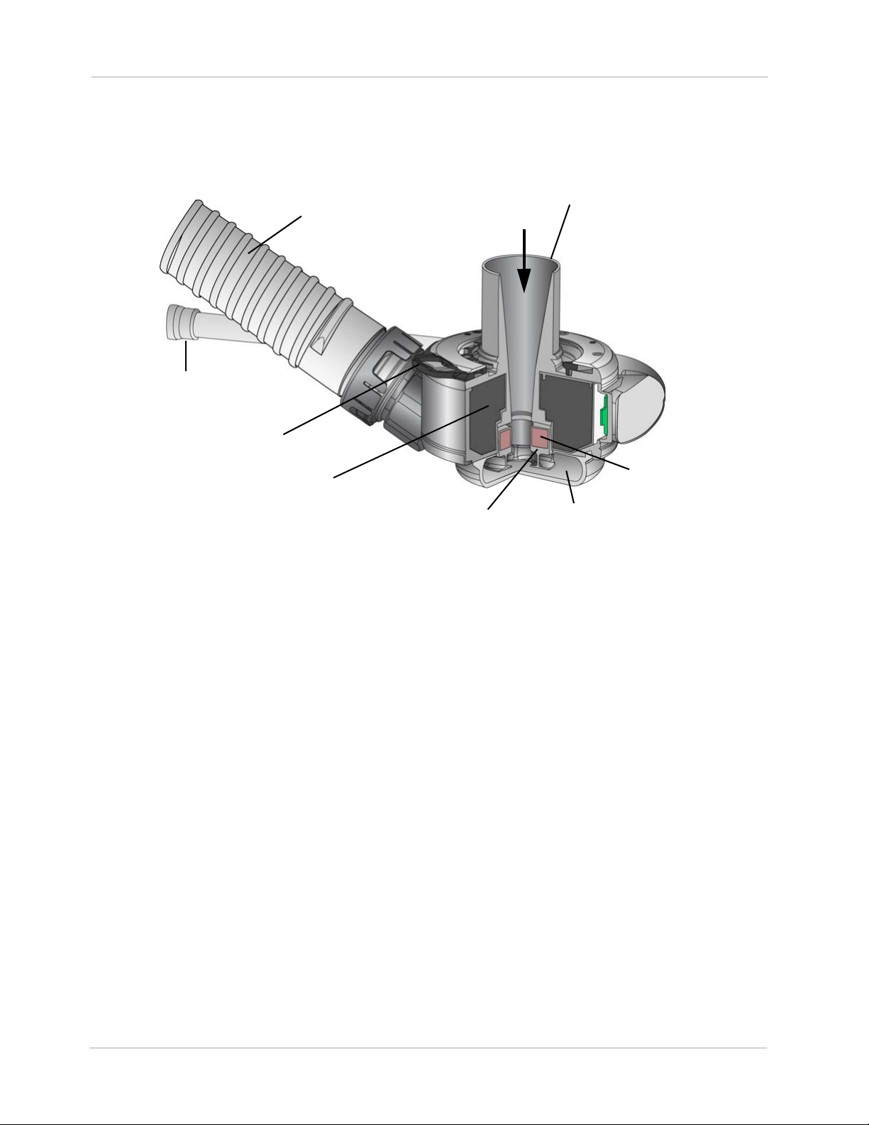
Outflow Graft
with Bend Relief
Slide Lock
Motor
Rotor
Pump
Chamber
Rotor Magnet
Inflow Cannula
Pump
Cable
The LVAD is a blood pump intended for implantation in the thorax of patients affected with advanced
heart failure. The LVAD contains an Inflow Cannula, a Pump Cover, a Lower Housing, a Screw Ring
to attach the Pump Cover to the Lower Housing, a Motor, the Outflow Graft, and a Pump Cable.
Figure 1.2 Left Ventricular Assist Device Components
The LVAD is surgically connected to the patient's circulatory system via an Inflow Cannula placed
into the left ventricular apex, and an Outflow Graft anastomosed to the ascending aorta. The LVAD is
a centrifugal pump: ventricular blood is drawn into the Inflow Cannula along a central axis and is
expelled at right angles by and between the impeller blades of a Rotor rotating about the central
axis. The fluid thus angularly accelerated collects and travels around a volute before it is diffused to
a desired pressure and flow rate by being directed tangentially into the Outflow Graft.
The Rotor is fully supported by magnetic levitation, obviating mechanical or fluid bearings and
essentially eliminating Rotor mechanical wear as a reliability factor. Both drive (i.e. rotation) and
levitation of the Rotor is accomplished using a single Stator comprising iron pole pieces, a back-iron,
copper coils, and position sensors. By measuring the position of a permanent magnet in the Rotor
and appropriately controlling the current in the drive and levitation coils, the radial position and
rotational speed of the Rotor is actively controlled. Because of the permanent magnet's attraction to
the iron pole pieces, the rotor passively resists excursion in the axial direction, whether such
excursion is translation or tilting.
The electronics and software necessary to control motor drive and levitation are integrated into the
Lower Housing with the Stator, and all of these plus the Rotor are regarded to comprise the Motor.
1-4
Page 14

Chapter 1 Introduction
The Inflow Cannula is a cylindrical conduit with external size and features similar to those of the
HeartMate II™. It is rigidly affixed to the Pump Cover. During the implantation procedure, a Coring
Tool is used to resect a plug of myocardium at the left ventricular apex to allow insertion of the Inflow
Cannula into the left ventricle. An Apical Attachment Cuff is sewn to the epicardium, and a slide lock
is used to secure the Inflow Cannula and establish hemostasis.
The Outflow Graft assembly consists of a sealed woven polyester graft and the hardware necessary
to attach the graft to the Pump Cover. The distal end of the graft is designed to be cut to desired
length and sutured to the ascending aorta by an end-to-side anastomosis (only the graft is to be cut,
not the bend relief). A reinforced tube serves as a bend relief around the Outflow Graft to prevent
kinking and abrasion. The bend relief can be attached or removed and reattached during the
implantation procedure. If necessary, the Outflow Graft may be detached from the Pump Cover,
permitting pump replacement without re-anastomosis.
A Pump Cable is permanently attached to the Lower Housing to establish electrical connection with
the enclosed Motor via a hermetically sealed feed-through. This Pump Cable is tunneled through
subdermal abdominal tissue via a Tunneling Tool and is exteriorized through a skin wound prepared
with a Skin Coring Punch at a location deemed optimal for the patient and his equipment. The Pump
Cable extends only a few inches through this site. It is extended with a Modular Cable, which
connects the Pump (through the Pump Cable) to a System Controller and is readily replaceable
without surgery if necessary. The Pump Cable and Modular Cable, once connected, comprise the
Driveline. The Driveline contains duplicate sets of three conductors: two for power and ground, and
a third for communication.
The HeartMate 3 System Controller is also part of the Left Ventricular Assist System (LVAS). The
System Controller is an extracorporeal interface device that receives power from the Power Module,
the Mobile Power Unit, or portable Batteries, and appropriately delivers that power to the LVAD. It is
the primary user interface and has several important functions:
• Operating condition display,
• Source of audible and visible alarms,
• Communication link for transferring event/period log and alarm information, and
• Battery backup in the case of full power disconnection.
1-5
Page 15

Chapter 1 Introduction
WARNING !
• A thorough understanding of the technical principles, clinical applications, and risks
associated with left ventricular support is necessary before using the HeartMate 3 Left
Ventricular Assist System. Read this entire manual before attempting implantation of the Left
Ventricular Assist Device or before caring for HeartMate 3 patients. Completion of Abbott
HeartMate 3 Surgical Training Program is also required prior to use.
• Understanding the operating and safety aspects of the HeartMate 3 Left Ventricular Assist
System is critical for safe and successful use.
• All users, including clinicians, patients, and caregivers, must be trained on system operation
and safety before use.
• All users, including clinicians, patients, and caregivers, must be trained on any HeartMate 3
power accessories (Mobile Power Unit, Battery Charger, or HeartMate 14 Volt Lithium-Ion
batteries) before use.
• Do not use the HeartMate 3 Left Ventricular Assist Device in pregnant women or in women
likely to become pregnant. A growing fetus may dislodge the pump, which may result in
device failure, catastrophic bleeding, or death. Instruct women of childbearing age to use
reliable contraception if sexually active. Blood thinners have been associated with birth
defects. Anticoagulation regimens are contraindicated during pregnancy.
• Do not modify this equipment without authorization from Abbott. The use of unauthorized
replacement parts may affect the electromagnetic compatibility of the Mobile Power Unit with
other devices. Potential interference may occur between the Mobile Power Unit and other
devices.
• Certain parts of the HeartMate 3 Left Ventricular Assist System are not compatible with other
HeartMate systems. Only use HeartMate 3 parts with the HeartMate 3 system.
• The HeartMate 3 pump may cause interference with implantable cardiac defibrillators (ICD).
If electromagnetic interference occurs it may lead to inappropriate ICD therapy. The
occurrence of electromagnetic interference with ICD sensing may require adjustment of
device sensitivity and/or repositioning the lead.
1-6
Page 16

Chapter 1 Introduction
CAUTION !
• Limited clinical data are available for the HeartMate 3 LVAS in patients with a body surface
area (BSA) less than 1.0 m2 (see HeartMate 3 Pediatric Patients with a BSA below 1.0 m2
on page A-67). The clinical decision to implant the HeartMate 3 in patients with a BSA less
than 1.0 m2 should be based on individualized assessment of body habitus and device fit.
• The HeartMate 3 LVAS sterilant residuals may cause adverse biological effects in patients
with a body mass
carcinogenicity, and reproductive effects.
• Clinical procedures (including LVAS settings) should be conducted under the direction of the
prescribing physician
• Do not try to repair any of the HeartMate 3 system components. If components need service,
contact appropriate
of <25 kg, including irritation, organ damage, mutagenicity,
(Authorized Personnel) only.
personnel.
• Notify appropriate personnel if there is a change in how the pump works, sounds, or feels.
• Counsel the patient to avoid contact sports and jumping activities while implanted with the
pump. Contact sports or jumping can cause bleeding or damage the pump.
• Care should be taken
strangulation from the system’s cables.
• If HeartMate 3 patients are approved for showering, they must always use the Shower Bag.
When installed properly, the Shower Bag protects external system components from water or
moisture. If external system components have contact with water or moisture, the pump may
stop.
when small children or pets are present. There is a potential for
Indications
The HeartMate 3 Left Ventricular Assist System is indicated for providing short- and long-term
mechanical circulatory support (e.g., as bridge to transplant or myocardial recovery, or destination
therapy) in adult and pediatric patients with advanced refractory left ventricular heart failure and
with an appropriate body surface area.
Contraindications
The HeartMate 3 Left Ventricular Assist System is contraindicated for patients who cannot tolerate, or
who are allergic to, anticoagulation therapy.
1-7
Page 17

Chapter 1 Introduction
Adverse Events
Adverse events that may be associated with the use of the HeartMate 3™ Left Ventricular Assist
System are listed below. Adverse events are listed in anticipated decreasing order of frequency,
except for death, which appears first as it is a non-reversible complication:
•Death
• Bleeding
• Cardiac Arrhythmia
• Localized Infection
• Device Malfunctions
• Right Heart Failure
•Respiratory Failure
•Driveline Infection
•Sepsis
•Renal Dysfunction
• Other Neurological Event (not stroke-related)
•Stroke
•Hypertension
• Psychiatric Episode
• Venous Thromboembolism
• Hepatic Dysfunction
• Arterial Non-Central Nervous System (CNS) Thromboembolism
• Pericardial Fluid Collection
• Pump Pocket or Pseudo Pocket Infection
• Myocardial Infarction
• Wound Dehiscence
• Hemolysis (not associated with suspected device thrombosis)
•Pump Thrombosis
Pre-Use Requirements
A thorough understanding of the technical principles, clinical applications, and risks associated with
left ventricular support is required before using the HeartMate 3™ Left Ventricular Assist System.
1-8
Page 18

Chapter 1 Introduction
It is suggested that patients possess a minimum 5th grade educational level and shall be versed in
basic computer literacy (i.e., Microsoft‡ Windows
This manual contains important warnings, cautions, and instructions for use. Read this entire manual
before implanting a HeartMate 3 Left Ventricular Assist Device or before caring for HeartMate 3
patients. Completion of Abbott HeartMate 3 Surgical Training Program is also required.
If you have questions after reading this manual, please contact Abbott for assistance. See Abbott
contact information on the Back Cover of this manual.
‡ and Office software).
1-9
Page 19
Chapter 1 Introduction
Equipment Overview
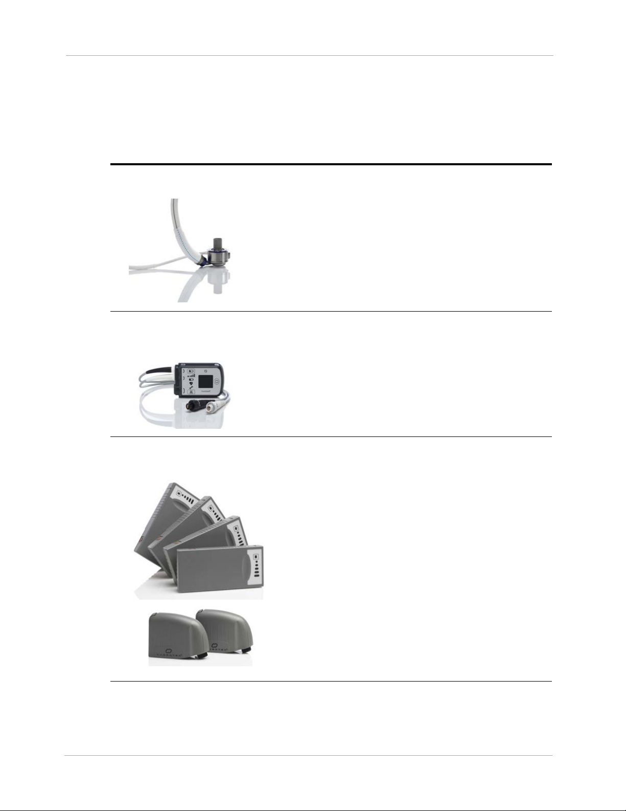
The table below introduces the main parts of the system, along with useful accessories. All of these
items are described in more detail later in this manual.
Left Ventricular
Assist Device
The HeartMate 3™ Left Ventricular Assist Device
(frequently called the “pump”) is implanted in the chest
below the heart. One end is inserted into the apex of the
left ventricle; the other end connects to the ascending
aorta. The pump diverts blood from the weakened left
ventricle and pumps it to the aorta.
For more information, see page 1-17.
System Controller
14 Volt Lithium-Ion Batteries &
14 Volt Battery Clips
The System Controller is a small computer that controls
and monitors system operation. The System Controller
uses lights, sounds, and on-screen messages to
communicate with users about operating status and alarm
conditions. A Driveline, which passes through the
patient’s abdomen, connects the implanted pump to the
System Controller.
For more information, see page 2-8.
Two HeartMate 14 Volt Lithium-Ion batteries are used to
power the system during battery-powered operation, such
as when AC electricity is not wanted or unavailable.
Batteries are used in pairs and are inserted into a 14 Volt
battery clip. Both batteries are discharged together (not
one, then the other). Two power cables are required to
transfer battery power to the System Controller. When
fully charged, a pair of HeartMate 14 Volt Lithium-Ion
batteries can power the system for up to 10–17 hours,
depending on the activity level of the patient.
1-10
For more information, see page 3-51.
Table 1.1 HeartMate 3™ System Components
Page 20

Chapter 1 Introduction
Modular Cable
Power Module
Power Module Patient Cable
The Driveline consists of two cables: the Pump Cable
and the Modular Cable. One end of the Pump
Cable connects to the pump implanted in the
patient’s abdomen. The other end of that cable exits
the patient’s body. One end of the Modular Cable is
connected to the Pump Cable and the other end
connects to the System Controller.
The Power Module is for clinical use. The Power Module
plugs into an AC to provide power to the HeartMate 3
system. The Power Module is used when the patient is
indoors, stationary, or sleeping. A sleeping patient may
not hear low battery power alarms. The System Controller
and the Power Module are connected through the Power
Module patient cable. The cable transfers power from the
Power Module to the System Controller.
For more information, see page 3-4.
The Power Module patient cable connects the Power
Module to the System Controller. Connections are made
between white-to-white and black-to-black connectors.
Mobile Power Unit
HeartMate Touch
Communication System
For more information, see page 3-15.
The Mobile Power Unit™ is for home or clinical use when
the patient does not require monitoring using the
HeartMate Touch™ Communication System. The Mobile
Power Unit is used when the patient is indoors, stationary,
or sleeping, as a sleeping patient may not hear low
battery power alarms. The System Controller and the
Mobile Power Unit are connected through the Mobile
Power Unit patient cable. The cable transfers power from
the Mobile Power Unit to the System Controller.
For more information, see page 3-34.
The HeartMate Touch Communication System provides
clinicians with the ability to wirelessly monitor a patient’s
HeartMate system, program system parameters such as
pump speed, assess and track alarm conditions, and
view and save performance data. Its use during Left
Ventricular Assist Device implantation is required.
For more information, see page 4-2.
Table 1.1 HeartMate 3™ System Components (Continued)
1-11
Page 21

Battery Charger
Shower Bag
Chapter 1 Introduction
The Battery Charger calibrates, charges, and tests the
HeartMate 14 Volt Lithium-Ion batteries that are used to
power the system during battery-powered operation.
For more information, see page 3-73.
The Shower Bag is used to protect external system
components from water or moisture—outside in heavy
rain or snow, and always for every shower. HeartMate 3
patients may be allowed to shower when the Driveline
exit site has healed and with permission from their doctor.
If external system components have contact with water or
moisture, the system may fail to operate properly or the
patient may get a serious electric shock.
For more information, see page 6-13.
System Controller Neck Strap
Belt Attachment
The System Controller Neck Strap attaches to the System
Controller and is used to wear the System Controller
around the neck or across the body.
For more information, see page 6-28.
The belt attachment provides another way to wear the
System Controller.
For more information, see page 6-33.
Table 1.1 HeartMate 3™ System Components (Continued)
1-12
Page 22

Consolidated Bag
Battery Holster
Chapter 1 Introduction
The Consolidated Bag is a convenient way to carry two
HeartMate 14 Volt Lithium-Ion batteries and attached
battery clips during battery-powered operation.
For more information, see page 6-37.
The Battery Holster provides a convenient way to wear
two HeartMate 14 Volt Lithium-Ion batteries and attached
battery clips.
For more information, see page 6-46.
Holster Vest
The Holster Vest provides another way to wear the
HeartMate 14 Volt Lithium-Ion batteries and attached
battery clips.
For more information, see page 6-52.
Table 1.1 HeartMate 3™ System Components (Continued)
1-13
Page 23

Travel Bag
Protection Bag
Chapter 1 Introduction
The Travel Bag provides a convenient way to carry and
transport the backup System Controller and spare
batteries.
For more information, see page 6-61.
The Protection Bag stores and protects the backup System
Controller.
For more information, see page 6-60.
ICU Cover
The disposable, non-sterile, single-patient use ICU Cover
is a location management accessory to secure the System
Controller to a visible location using the provided Clip.
For more information, see the ICU Cover Instructions for
Use shipped with the ICU Cover.
Table 1.1 HeartMate 3™ System Components (Continued)
1-14
Page 24

Chapter 1 Introduction
Required, Backup, and Optional Components and Equipment
The HeartMate 3™ Left Ventricular Assist System is designed for use both inside and outside of the
hospital. Specific system components and equipment may be required for each setting. Components
and equipment that are required for implant and ICU transfer are listed in Table 1.2.
.
Components Required for Implantation
and ICU Transfer
HeartMate 3 Implant Kit* Required Required
System Controller with 11 Volt Lithium-Ion
Backup Battery
Power Module with patient cable Required Required
Tablet for use with the HeartMate Touch App
and HeartMate Touch Wireless Adapter
One set of 4 rechargeable HeartMate 14 Volt
Lithium-Ion batteries
One set of 2 HeartMate 14 Volt battery clips and
battery clip cables
Battery Charger Required Not required
HeartMate 3 Tunneling Lance and Handle** Required
Apical coring knife** Optional
Primary Backup
Required Required
Required Required
Required Not required
Required Not required
Skin coring punch (6 mm)* Optional
Apical cuff** Optional
Outflow Graft Thread protectors** Optional
Modular Cable Cap Optional
* Some “Optional” items are included in the HeartMate 3 Implant Kit.
** Also available separately.
1-15
Table 1.2 Components for Implant
Page 25

Chapter 1 Introduction
Components and equipment that are required for a discharged patient are listed in
Table 1.3. Patients discharged to a lower care facility or to their homes must be trained in device
use, maintenance, and troubleshooting. In addition, device malfunction may necessitate emergency
treatment. Therefore, patients should not be more than two hours from a healthcare facility that has
trained personnel who are capable of treating a HeartMate 3 patient.
Components for a Discharged Patient Primary Backup
Implanted HeartMate 3 Left Ventricular Assist
Device
System Controller with 11 Volt Lithium-Ion
backup battery
Mobile Power Unit Required Not Required
One set of 4 rechargeable HeartMate 14 Volt
Lithium-Ion batteries
One set of 2 HeartMate 14 Volt battery clips Required Not Required
Battery Charger Required Not Required
One set of wear & carry accessories,
including: Shower Bag, Protection Bag for
backup System Controller, holster vest, belt
attachment accessory, and System Controller
Neck Strap
HeartMate 3 Patient Handbook Required Not Required
Required n/a
Required Required
Required Required
Required Not Required
Table 1.3 Components for Discharged Patients
CAUTION !
Confirm that the patient’s backup System Controller has had the 11 Volt Lithium-Ion backup
battery installed and the time and date have been set.
WARNING !
A backup System Controller and charged batteries must remain with the patient at all times
for use in an emergency. Patient and caregiver training must address this crucial need.
1-16
Page 26
Chapter 1 Introduction
Principles of Operation
The HeartMate 3™ LVAD is a centrifugal pump that produces flow in the patient's circulatory system
by angularly accelerating and expelling blood that enters it. From a clinical viewpoint, this
mechanical pump works in concert with the native heart to which it is attached. It is a parallel
arrangement - ventricular blood may flow either through the LVAD or the aortic valve to reach the
aorta - the proportion of which depends greatly upon the degree of the patient's cardiac function
and the set-speed of the LVAD.
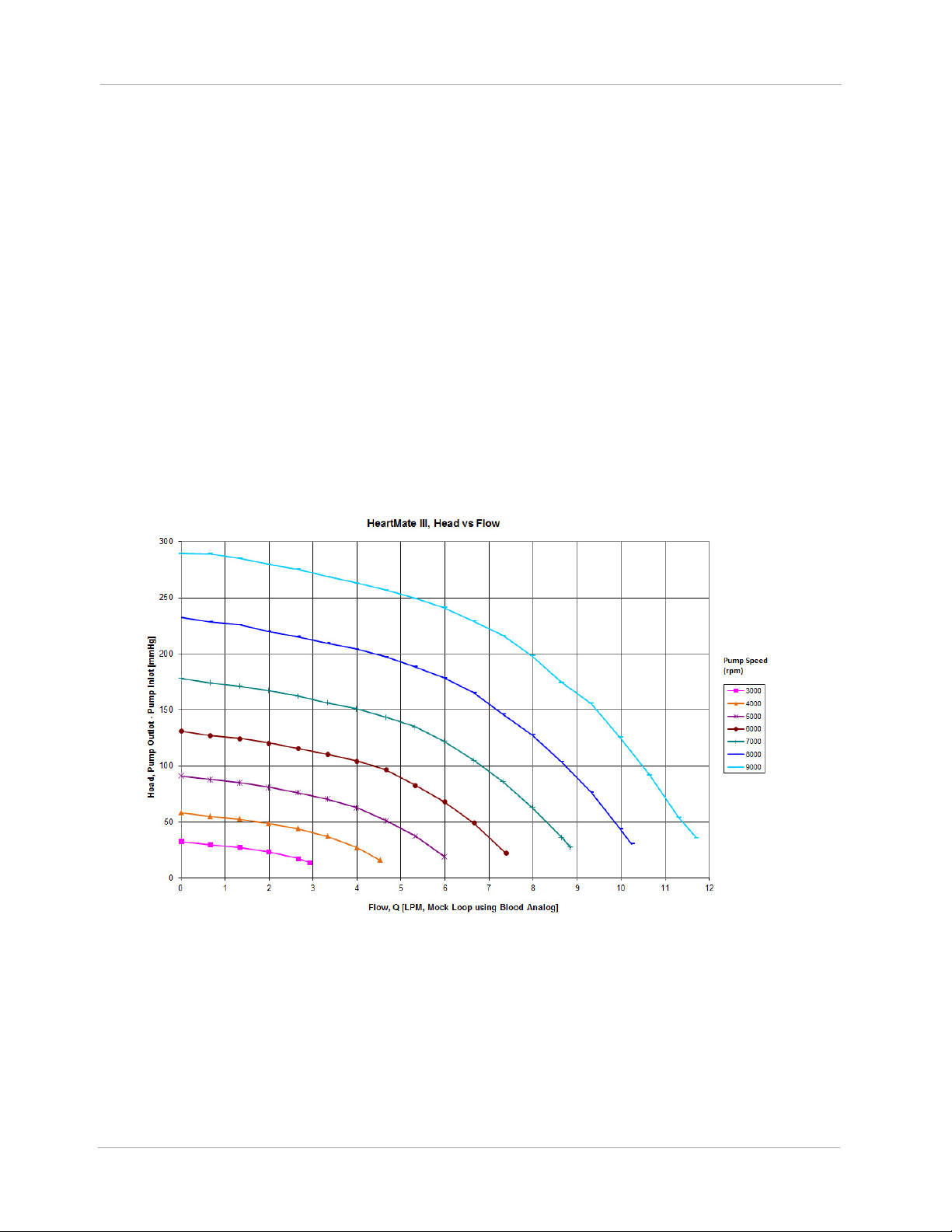
As for any continuous flow pump (axial, centrifugal, or mixed), the volume flow rate through the
pump is directly related to the pressure across the pump and inversely related to the resistance.
Clinically, the volume flow rate through the Pump is the difference between aortic and left ventricular
pressure, and systemic vascular resistance. This relationship can be characterized at any rotor
speed, and the family of curves derived in steady-state at different speeds is commonly termed “H-Q
curves”, or the pressure head (H) - volume flow rate (Q) relationship. HeartMate 3 H-Q curves are
shown in Figure 1.3.
Figure 1.3 Pressure Head-Flow (H-Q) Relationship
Similarly, there is a characteristic relationship between pump power and volume flow rate. Total
power consumption includes hydraulic power (useful blood pressure and flow), viscous losses,
electrical resistance losses, and others. The relationship between hydraulic power and volume flow
1-17
Page 27
Chapter 1 Introduction
rate is always direct, but the various losses have a multitude of dependencies that make inflections in
the relationship possible.
In general, if the speed is set optimally, LVAD flow will be unidirectional towards the aorta and much
greater than cardiac output, which may be minimal or zero if the presence of the LVAD keeps the
aortic pressure above the ventricular pressure even during systole. If the LVAD speed is set too high,
the inflow pressure may fall to the extent that it attempts to recruit blood from the left ventricle, left
atrium, and pulmonary vasculature that simply is not there, resulting in collapse of the left ventricle
and potential arrhythmia. The HeartMate 3 LVAS employs a feature called Pulsatility Index (PI)
Detection to recognize and avert this condition. When the degree of pulsatility measured in the
electrical current waveform has fallen below a preset value, the system regards this as a risk of
ventricular suction and quickly lowers the rotor speed to a preset, programmable Low Speed Limit,
then immediately but gradually returns the rotor to its original speed. The HeartMate 3 has an
intrinsic limit somewhat above 9000rpm. The system accordingly precludes setting the speed above
9000rpm. Conversely, if the LVAD speed is set too low, support for the failing heart may be
insufficient. The HeartMate 3 LVAS uses the same Low Speed Limit mentioned above to limit how low
the speed may be set. This is to avoid profound retrograde flow (aorto-ventricular shunt). The Low
Speed Limit is settable within a range to accommodate customization for a variety of patients.
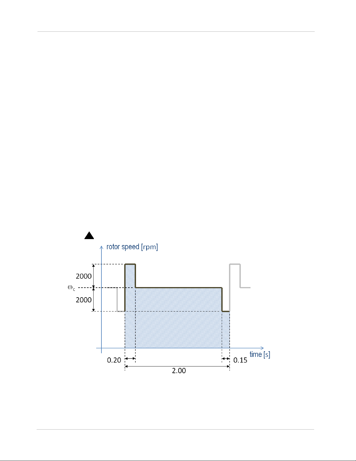
The HeartMate 3 employs a feature called Artificial Pulse that adds an element to the discussion
about rotor speed (Figure 1.4). Although the clinician will set only a single speed,
in Figure
c
1.4, the rotor speed will periodically depart from this value in order to contribute a flow disruption
that in some ways mimics native cardiac contractility. This artificial pulse “beats” 30 times per
minute, asynchronously with the heart. The Artificial Pulse mode is indicated on the System Controller
by the use of a ( ) symbol.
1-18
Figure 1.4 Artificial Pulse
Page 28

Chapter 1 Introduction
Explanation of Parameters
Speed
The HeartMate 3™ Left Ventricular Assist Device operates at a fixed speed (see Optimal Fixed Speed
on page 4-25) determined by the physician during a speed ramp study.
Note: The term “fixed speed” is a speed fixed, or set, by the clinician, i.e.,
Figure 1.4. This should not be confused with the concept of a constant speed mode, as opposed to
an artificial pulse mode. Either mode requires a fixed speed, set by the clinician.
A pre-programmed artificially induced pulse is intermittently generated, changing pump speed. The
“low speed limit” for the device is the lowest speed at which it allowed to operate.
During a suction event, device speed drops to the “low speed limit” and then ramps up to the fixed
speed unless another Pulsatility Index (PI) event is detected. If another PI event is detected, the device
drops to the “low speed limit” again and then ramps back up. This cycle repeats as long as PI events
are detected. Large changes in speed may indicate an abnormal condition that should be evaluated
for cause.
c
in
Power
Device power is a direct measurement of pump motor voltage and current. Changes in pump speed,
flow, or physiological demand can affect pump power. Gradual power increases (over hours or
days) may signal thrombus deposits inside the pump, aortic or insufficiency. Gradual power
decreases may indicate an obstruction of flow and should be evaluated. Depending on the speed of
the pump, power values greater than 10 to 12 watts (W) also can indicate the presence of a
thrombus. Abrupt changes in power should be evaluated for cause.
Flow
Device flow and power generally retain a linear relationship at a given speed. However, while
power is directly measured by the System Controller, the reported flow is estimated, based on
power. Since the flow displayed on the System Controller is a calculated value, it somewhat
underestimates actual flow at high flows.
Any increase in power not related to increased flow (such as thrombus) causes erroneously high flow
readings. Conversely, an occlusion of the flow path decreases flow and causes a corresponding
decrease in power. In either situation, pump output should be assessed.
1-19
Page 29

Chapter 1 Introduction
Pulsatility Index (PI)
When the left ventricle contracts, the increase in ventricular pressure causes an increase in pump
flow during cardiac systole. The magnitude of these flow pulses are measured and averaged over
15-second intervals to produce a “Pulsatility Index” (occasionally shortened to “PI” for on-screen
messages).
The PI calculation represents cardiac pulsatility. PI values typically range from 1 to 10. In general,
the magnitude of the PI value is related to the amount of assistance provided by the pump. Higher
values indicate more ventricular filling and higher pulsatility (ie, the pump is providing less support to
the left ventricle). Lower values indicate less ventricular filling and lower pulsatility (ie, the pump is
providing greater support and further unloading the ventricle).
PI values should be routinely monitored and should not vary significantly during resting conditions.
Under otherwise stable conditions, a significant drop in value may indicate a decrease in circulating
blood volume. Pulsatility Index values near or above 10 may indicate potential problems. For PI
values near 10 or above, please contact Abbott. For Abbott contact information, see the Back Cover
of this manual.
IMPORTANT! One single pump parameter is not a surrogate for monitoring the overall clinical
status of the patient. Any change in parameters should be evaluated with all clinical considerations
taken into account.
1-20
Page 30

SYSTEM OPERATIONS
This section describes the primary system operations of the HeartMate 3™ Left Ventricular Assist
System.
HeartMate 3™ Left Ventricular Assist Device Overview - - - - - - 2-2
2
System Controller Overview - - - - - - - - - - - - - - - - - - - - 2-8
The Backup System Controller - - - - - - - - - - - - - - - - - - - 2-45
2-1
Page 31

Chapter 2 System Operations
HeartMate 3™ Left Ventricular Assist Device Overview
The HeartMate 3™ Left Ventricular Assist Device (Figure 2.1) is a centrifugal flow rotary heart
pump that is connected in parallel to the native circulation. The inflow cannula of the Left Ventricular
Assist Device attaches to the apex of the left ventricle. Its sealed outflow graft connects to the
ascending aorta (Figure 2.2). Frequently, the HeartMate 3 Left Ventricular Assist Device is called
the “pump.”
Figure 2.1 HeartMate 3™ Left Ventricular Assist Device
2-2
Page 32

Chapter 2 System Operations
Figure 2.2 HeartMate 3™ Implant
Configuration
Inflow
Cannula
Outflow
Graft
Function
The LVAD uses a rotary blood pump to generate flow and assist the left ventricle. It is a
centrifugally-configured device so that the paths of the entering and exiting flow stream are
perpendicular to the pump’s axis. The device has only one moving part, the rotor assembly, which is
fully (i.e., actively) magnetically levitated within the flow stream. The pump is driven by an external
power source via a Driveline.
The pump operates in parallel with the heart, such that either can supply blood to the aorta. The
LVAD can generate a blood flow up to 10 liters per minute (lpm). Blood enters the pump from the left
ventricle through an Inflow Cannula. Blades on the spinning rotor move the blood through the pump
to an Outflow Cannula and ultimately to the native circulation.
Implant Location
The HeartMate 3™ Left Ventricular Assist Device is implanted in the chest (see Figure 2.2). For
more information, see Implant Procedures on page 5-35
.
2-3
Page 33

Chapter 2 System Operations
The HeartMate 3 LVAD is part of the Left Ventricular Assist System (Figure 2.3).
Figure 2.3 HeartMate 3™ LVAS During Battery-Powered Operation
Driveline
The Driveline consists of two cables: the Pump Cable, that extends from the Left Ventricular Assist
Device through the skin, and the Modular Cable which connects the Pump Cable to the System
Controller. The Driveline contains six wires—three primary wires and three backup wires—that
power the Pump Motor and facilitates communication with the System Controller.
To reduce infection, the Driveline is covered with woven polyester, which encourages tissue ingrowth
at the skin line. Over time, tissue bonds to the textured material and anchors the external surface of
the Driveline to the surrounding tissue. After emerging from the body, the Driveline has a Modular
Connector that joins the Pump Cable to the Modular Cable. The Modular Cable then has an electric
connector that attaches to the System Controller.
Experience with other LVADs has shown that wear and fatigue of the Driveline may result in damage
that can interrupt device function. Such damage may require another operation to replace the pump,
or result in death. For information about caring for the Driveline, see Care of the Driveline on page
8-5.
2-4
Page 34

Chapter 2 System Operations
Pump Cable
Modular Cable
Driveline (both
cables when
connected)
Driveline damage due to wear and fatigue may occur in both the externalized (Modular Cable) and
implanted portions (Pump Cable) of the lead. Damage to the conductors within the Driveline may or
may not be preceded by visible damage to the outer layer of the Driveline.
Driveline damage may be evidenced by the following:
• A Driveline Power Fault, Driveline Comm Fault, or Communication Fault alarm on the System
Controller.
• Transient alarms due to short or open circuits, often associated with movement of the patient or
the lead.
• Fluid leakage from the external portion of the Pump Cable.
• Cessation of pumping.
WARNING !
If the Driveline or Driveline connector appears damaged, contact Abbott for assistance. Refer
to the Back Cover of this manual for Abbott contact information.
X-ray images and System Controller log files are useful to assess the extent and location of the
damage. If the Driveline or Driveline conductors are damaged internal to the patient’s body, the
pump should be replaced as soon as possible. If it has been determined that the damage has been
detected in the Modular Cable, it can be replaced. Please refer to Replacing the Modular Cable on
page 2-62 for the procedure for exchanging the Modular Cable.
Figure 2.4 Driveline
2-5
Page 35

Chapter 2 System Operations
Powering the Pump Motor
The Left Ventricular Assist Device Motor is powered through the System Controller by one of three
sources: the Power Module or the Mobile Power Unit that is connected to an AC electrical outlet (see
Using the Power Module on page 3-4), or two HeartMate 14 Volt Lithium-Ion Direct Current (DC)
Batteries (see Using HeartMate 14 Volt Lithium-Ion Batteries on page 3-51).
Note: The Backup System Controller is charged every six months.
Acceptable Operating Conditions
For safe and optimal use of HeartMate system components, follow the operating guidelines listed
here. Operating system components outside of the environmental parameters listed below may affect
device operation.
Equipment
Power Module
Mobile Power Unit
Tablet for use with
the HeartMate
™ App
Touch
HeartMate Touch
Wireless Adapter
HeartMate 14 Volt
Lithium-Ion
Batteries
Battery Charger
a
Acceptable
Temperature
Range F (C)
32°F to 104°F
(0°C to 40°C)
32°F to 104°F
(0°C to 40°C)
32°F to 95°F
(0°C to 35°C)
32°F to 104°F
(0°C to 40°C)
32°F to 104°F
(0°C to 40°C)
32°F to 104°F
(0°C to 40°C)
Relative
Humidity
20% to 75%
20% to 93%
20% to 95%
20% to 75%
20% to 75%
20% to 75%
Air Pressure
mm Hg (hPA)
525 to 795
(700 to 1060)
525 to 795
(700 to 1060)
535 to 795
(710 to 1060)
525 to 795
(700 to 1060)
525 to 795
(700 to 1060)
525 to 795
(700 to 1060)
System Controller,
Backup System
Controller
11 Volt
Lithium-Ion
Backup Battery
a, b
32°F to 104°F
(0°C to 40°C)
32°F to 104°F
(0°C to 40°C)
2-6
20% to 93%
20% to 93%
525 to 795
(700 to 1060)
525 to 795
(700 to 1060)
Table 2.1 Operating Conditions
Page 36

Chapter 2 System Operations
a Standby components (extra 14 Volt Lithium-Ion batteries, backup System Controller) should be maintained at conditions within the
acceptable ranges so that they are available for immediate use. A backup System Controller and charged batteries must remain with
the patient at all times for use in an emergency. Patient and caregiver training must address this crucial need.
Every six months, the “sleeping” backup System Controller must be connected to a power source to charge the 11 Volt Lithium-Ion backup battery inside.
b
If the 11 Volt Lithium-Ion backup battery inside the backup System Controller is not charged every six months, its charge level will diminish and there may
not be sufficient power to support the pump if the backup System Controller is in use during a power emergency (see Maintaining Backup System Controller
Readiness: Six Month Charging and Self Test
on page 2-51).
2-7
Page 37

Chapter 2 System Operations
HeartMate 3
Left Ventricular
Assist Device
System Controller
Driveline
System Controller Overview
The HeartMate 3™ System Controller acts as the central power and communication hub for the
HeartMate 3 LVAS. It passes power from the Power Module, the Mobile Power Unit, Lithium-Ion
Batteries, or its own integrated emergency backup supply, down to the LVAD via the Driveline. The
HeartMate 3 System Controller constantly monitors system performance through communication with
the implanted LVAD and Controller internal measurements and alerts the user to any alarm conditions
by activating membrane panel LEDs and integrated audio annunciators. Further information on alarm
conditions as well as system status can be attained by the user from the front panel LCD on the
System Controller. When connected to a HeartMate Touch™ Communication System, the System
Controller sends information regarding the System Controller and Pump Status once per second to
provide additional information to the user. This link also allows the clinician to set new patient
operating parameters (e.g. pump speed) and provides a link for downloading trend and/or event
recorder data.
The System Controller has been designed with redundant power and communication lines to the
pump Driveline. This not only provides for a robust continuous operation of the implanted pump in
the event of a fault situation, but also alerts the user to possible Driveline degradation.
The System Controller is the chief decision making component of the system. It instructs the pump at
which speed to operate, either by passing a command sent by the HeartMate Touch Communication
System or when in Power Saver mode or at a Pulsatility Index (PI) event detection.
The System Controller connects to the LVAD
via a Driveline that passes through the
patient’s abdomen. The Driveline carries
power to the pump. The Driveline also
supplies information from the pump to the
System Controller (Figure 2.5).
The System Controller uses sounds, lights,
symbols, and on-screen messages to
communicate with users (Figure 2.6).
Figure 2.5 HeartMate 3™ Left Ventricular Assist System
2-8
Page 38

Chapter 2 System Operations
System Controller
Driveline Connector
Backup
Battery
(inside)
User
Interface
Power Cable
Connectors
• System Controller Driveline
Connector: links the Modular
Cable portion of the Driveline
to the System Controller.
• Power Cable Connectors: link
external power source (Power
Module, Mobile Power Unit, or
2 HeartMate 14 Volt
Lithium-Ion Batteries) to the
System Controller.
• User Interface: buttons, lights,
and screen where system data,
alarms, and user instructions
appear.
• Backup battery: located inside
the System Controller, powers
the pump for at least 15
minutes during a power-loss
emergency.
Power Cable
Connectors
Red Button
System Controller Driveline
Connector Alignment Arrow
System Controller Driveline
Connector
Safety Lock
Driveline Cable
Connector White
Alignment Arrow
Figure 2.6 System Controller Major Components
2-9
Page 39

Chapter 2 System Operations
The System Controller is described in the following sections:
System Controller User Interface Overview
This section describes the visual display of system operations and
on-screen messages.
System Controller Driveline Connector
This section provides instructions on connecting and disconnecting the
Driveline.
System Controller Power Cable Connectors
This section describes two power cables on the System Controller
(one white and one black) that connect the System Controller to either
the Power Module, the Mobile Power Unit, or two 14 Volt Lithium-Ion
batteries.
See page 2-14.
See page 2-20.
See page 2-26.
Performing a System Controller Self Test
This section provides instructions on how to perform a daily self test to
check the function of the System Controller’s audible and visual
alarms.
See page 2-29.
System Controller Battery Power Gauge
This section describes the battery power gauge function to show the
approximate charge status of the power source that is connected to
the System Controller’s power cables.
See page 2-30.
System Controller Operating Modes
This section describes the System Controller’s three operating modes
(Run, Sleep, and Charge) and provides an overview with instructions
on how to switch between modes.
See page 2-33.
System Controller Backup Battery Power
This section provides a functional overview with instructions on how
to replace the 11 Volt Lithium-Ion backup battery that is inside the
System Controller.
2-10
See page 2-39.
Page 40

Chapter 2 System Operations
System Controller Warnings and Cautions
WARNING !
• Check the System Controller Driveline connector to confirm that the Driveline is securely
inserted in the socket. If the Driveline disconnects from the System Controller, the pump stops.
If the Driveline disconnects from the System Controller, promptly reconnect it to resume pump
operation.
• At least one System Controller power cable must be connected to a power source (Power
Module, Mobile Power Unit, or two HeartMate 14 Volt Lithium-Ion batteries) at all times.
• Keep the System Controller power cables dry and away from water or liquid. If the System
Controller power cables come into contact with water or liquid, the system may fail to operate
properly or you may get a serious electric shock.
• Do not allow patients to swim or take tub baths while implanted with the Left Ventricular Assist
Device. Patient immersion in water may cause the device to stop.
• Do not allow patients to shower without a doctor’s permission. HeartMate 3™ patients may
be allowed to shower, but only after sufficient post-operative healing and with a doctor’s
permission.
• If external system components have contact with water or moisture, the Pump may stop. If a
HeartMate 3 patient is approved for showering, he or she must always use the Shower Bag
during every shower. The Shower Bag protects external system components from water or
moisture.
• The 11 Volt Lithium-Ion backup battery should be used only for temporary support during a
power-loss emergency. The 11 Volt Lithium-Ion backup battery inside the HeartMate 3 System
Controller provides enough power to run the implanted HeartMate 3 pump for at least 15
minutes if the main power source (either the Power Module, Mobile Power Unit, or two
HeartMate 14 Volt Lithium-Ion batteries) is disconnected or fails. Inappropriate use of the 11
Volt Lithium-Ion backup battery may result in diminished run time during a power-loss
emergency.
• Do not use damaged, defective, or expired 11 Volt Lithium-Ion backup batteries in the System
Controller. Using a damaged, defective, or expired System Controller backup battery may cut
operating time during an emergency or cause the pump to stop.
• Use only a Abbott-supplied HeartMate 14 Volt Lithium-ion battery with the HeartMate 3
System Controller. Using another battery may cause the pump to stop.
• Do not open, crush, heat above 104°F (40°C), or incinerate batteries because of the risk of
fire and burns. Follow manufacturer’s instructions.
• Malfunction of the 11 Volt Lithium-Ion backup battery may cause the System Controller to
become excessively hot. If this occurs, switch to the backup System Controller.
2-11
Page 41

Chapter 2 System Operations
CAUTION !
• Do not drop the System Controller or subject it to extreme physical shock.
• Instruct patients (and family member or caregiver) to advise hospital personnel immediately if
they drop the System Controller. Emphasize to users the importance of not waiting to report a
dropped System Controller, even if everything seems fine. Dropping the System Controller
can cause trauma or tissue damage at the Driveline exit site, which can increase the patient’s
risk of serious infection.
• Instruct the patient to stabilize their Driveline at all times to avoid pulling on or moving the
Driveline at the exit site. Pulling on or moving the Driveline can keep the exit site from healing
or damage an already healed exit site. Exit site trauma or tissue damage can increase the
patient’s risk of getting a serious infection. Emphasize to the patient and/or family member
or caregiver the importance of not pulling on or moving the Driveline.
• Do not twist, kink, or sharply bend the Driveline, System Controller power cables, Power
Module patient cable, or Mobile Power Unit patient cable, which may cause damage to the
wires inside, even if external damage is not visible. Damage to the Driveline or cables could
cause the Left Ventricular Assist Device to stop. If the Driveline or cables become twisted,
kinked, or bent, carefully unravel and straighten.
• The 11 Volt Lithium-Ion backup battery inside the backup System Controller must be charged
at least once every six months. Failure to charge the 11 Volt Lithium-Ion backup battery inside
the backup System Controller may result in diminished or no support during a power-loss
emergency when the backup System Controller is in use.
• Damage to the redundant electrical wires inside the Driveline can occur that is not visible to
the user. Signs of Driveline damage include (but are not limited to):
- The System Controller alarming when the Driveline is moved or when the patient
changes position.
- Driveline Power Fault or Driveline Communication Fault yellow wrench and audio alarm
(see System Controller User Interface Components on page 2-15).
- Fluid oozing from the external portion of the Pump Cable.
- Pump stoppage.
• When connecting power cable connectors, do not try to join them together without first
aligning the half circles inside the connectors. Joining together misaligned power cable
connectors may damage them.
2-12
Page 42

Chapter 2 System Operations
CAUTION ! (Continued)
• Never use tools to tighten power cable connectors; securely hand tighten only. Using tools
may damage the connectors.
• Confirm that the patient’s backup System Controller has had the 11 Volt Lithium-Ion backup
battery installed and the time and date have been set.
• A backup System Controller and charged batteries must remain with the patient at all times
for use in an emergency. Patient and caregiver training must address this crucial requirement.
• The System Controller uses lights, sounds, and on-screen messages to communicate with users
about system operation. HeartMate 3 patients with sight or hearing impairment may need
extra help using the System Controller.
• Do not place the System Controller on bare skin for an extended time. The System Controller
surface temperature can become uncomfortably warm, especially when the room
temperature is above 104°F (40°C).
2-13
Page 43

Chapter 2 System Operations
Battery Button
Cable
Disconnect
Symbols
Status Symbols
Silence Alarm Button
Pump
Running
Symbol
User
Interface
Screen
Display
Button
System Controller User Interface Overview
The user interface on the System Controller is the primary interface for users during routine system
operation. It uses sounds, lights, symbols, and on-screen messages to communicate about how the
system is working. The user interface provides a visual display of system operation and on-screen
messages that instruct how to respond to alarms and other situations (Figure 2.7).
HeartMate 3™ patients (and their family members/caregivers) must be thoroughly trained on how to
interpret and use the user interface prior to discharge (see Educating and Training Patients, Families,
and Caregivers on page 6-67).
For situations that require attention, and depending on the urgency, the System Controller issues
include one of two types of alarms: hazard and advisory. Hazard alarms occur for conditions that
are potentially life threatening for the patient and require immediate attention. Advisory alarms are
important, but not life threatening. For more information on System Controller alarms and how to
resolve them, see Alarms and Troubleshooting on page 7-1.
2-14
Figure 2.7 System Controller User Interface
Page 44

Chapter 2 System Operations
System Controller User Interface Components
The buttons, lights, symbols, and display screen on the user interface are introduced below in Table
2.2.
Pump Running
Symbol
The Pump Running symbol on the user interface is illuminated green when
the Left Ventricular Assist Device is running.
Low Battery
Alarm
Yellow Wrench
Alarm
Red Heart Alarm
The red low battery symbol illuminates when less than 5 minutes of
battery power remain (applicable only during 14 Volt Lithium-Ion
battery-powered operation).
This is a Hazard alarm. When the red battery symbol illuminates,
immediately replace the depleted batteries with a fully-charged pair, or
switch to the Power Module or the Mobile Power Unit.
For more information, see page 7-15.
The yellow wrench symbol illuminates when the System Controller detects
a mechanical, electrical, or software issue with the system.
This is an Advisory alarm. When the yellow wrench illuminates, check
the screen for troubleshooting instructions.
For more information, see page 7-8.
The red heart symbol illuminates when the System Controller detects a
problem that could cause serious injury or death.
This is a Hazard alarm. When the red heart illuminates, check the
screen for instructions and take immediate action to resolve the problem.
For more information, see page 7-6.
Black Power
Cable Alarm
The yellow light near the black power cable connector illuminates when
the black power cable becomes loose or disconnects from the System
Controller.
This is an Advisory alarm. If the black power cable disconnects or
becomes loose, promptly restore the connection.
For more information, see page 7-17.
Table 2.2 System Controller Symbols, Alarms, Buttons
2-15
Page 45

Chapter 2 System Operations
White Power
Cable Alarm
Driveline
Connector Alarm
Battery Power
Gauge
The yellow light near the white power cable connector illuminates when
the white power cable becomes loose or disconnects from the System
Controller.
This is an Advisory alarm. If the white power cable disconnects or
becomes loose, promptly restore the connection.
For more information, see page 7-17.
The red light near the Driveline connector illuminates when the Driveline
becomes loose or disconnects from the System Controller.
This is a Hazard alarm. If the Driveline loosens or disconnects from the
System Controller, promptly restore the connection. If the Driveline is not
reconnected immediately, the pump stops.
For more information, see page 7-13.
The battery power gauge shows the approximate charge status of the
power source that is connected to the System Controller’s white and black
power cables—either the 14 Volt Lithium-Ion batteries or the Power
Module. The number of green bars means power remaining. The more
green bars mean more power remaining.
For more information, see page 2-30.
Yellow diamond = less than 15 minutes of battery power remain.
Appearance of this symbol indicates an Advisory alarm. If the yellow
diamond comes on, promptly replace the low batteries with two
fully-charged batteries, or switch to the Power Module or the Mobile
Power Unit. Do this as soon as possible.
For more information, see page 7-18.
IMPORTANT! The battery power gauge does not show the
charge status of the System Controller’s backup battery (the battery
inside the System Controller). To check the status of the System
Controller’s backup battery, see Viewing Pump and System Information on page 2-18.
Table 2.2 System Controller Symbols, Alarms, Buttons (Continued)
2-16
Page 46

Chapter 2 System Operations
The battery button is used for the following:
• Operating the battery power gauge: Press and release the
battery button.
For more information, see page 2-30.
Battery Button
Silence Alarm
Button
• Starting a System Controller self test: Press and hold the
battery button for 5 seconds and then release it. Perform a self test
daily on your running System Controller, and monthly on your backup
System Controller when it is in Charge Mode.
For more information, see page 2-29.
• Putting a running System Controller into Sleep Mode:
When a System Controller is no longer in use, it can be put to sleep
by disconnecting the Driveline and power source, and pressing and
holding the battery button for 5 seconds and then releasing it.
For more information, see page 2-38.
The silence alarm button is used for the following:
• Silencing an active alarm: Press and release the silence alarm
button to silence an active alarm on the System Controller. How long it
is silenced depends on the alarm (see Alarms and Troubleshooting on
page 7-1). The LCD screen on the System Controller will display the
audio alarm silence symbol.
IMPORTANT! Using the silence alarm button only silences the
alarm. It does not fix the alarm condition.
• Viewing the last six System Controller alarms on the
screen: Press and release the silence alarm button ( ) and the
display button ( ) at the same time to display the last six System
Controller alarms on the screen.
Display Button
For more information, see page 7-3.
The display button activates the information display screen. Press and
release the display button one or more times repeatedly to display
information about pump speed, power, flow, pulsatility index, and the
charge status of the System Controller’s 11 Volt Lithium-Ion backup
battery. The display button is functional only when a System Controller is
in use.
For more information, see page 2-19.
Table 2.2 System Controller Symbols, Alarms, Buttons (Continued)
2-17
Page 47

Chapter 2 System Operations
Pulse Mode
The presence of the black triangle indicates that the HeartMate 3 system
is operating in Pulse Mode. Once every 2 seconds, the HeartMate 3
pump will automatically modify its speed to create an artificial pulse.
Table 2.2 System Controller Symbols, Alarms, Buttons (Continued)
Viewing Pump and System Information
Viewing information about the pump is useful when recording daily values or trying to resolve system
problems on the telephone. When the System Controller is running, the user interface can display the
following information about current system operations:
• Speed
• Mode (indicated as Pulse Mode by symbol)
•Flow
• Pulsatility Index (abbreviated as “PI” on the screen)
•Power
• Charge status of the System Controller’s backup battery (11 Volt Lithium-Ion)
To view information on the user interface screen, press and release the display button ( ). Each
push of the display button brings up a new screen. Each screen illuminates for 15 seconds before it
goes black, unless another button is pushed. The screens are always displayed in the same order,
starting with the first (Speed) screen. A dot at the bottom of each screen provides navigational
information about which of the five screens is in view.
2-18
Page 48

Chapter 2 System Operations
Table 2.3 shows the display sequence.
Button
Press
Press
Press
Press
Press
Press
Description
Press display button
ONCE
Press display button
TWO times
Press display button
THREE times
Press display button
FOUR times
Press display button
FIVE times
Screen
Displayed
(Example)
Meaning
Pump speed in revolutions per minute
(RPM)
Triangle indicates that the pump
is in Pulse Mode.
Pump flow in liters per minute (LPM)
Pulsatility Index (PI)
Power in watts (W)
The System Controller’s backup battery
(located inside the System Controller
and used to temporarily run the pump
during a power emergency) has three
charge status states:
1. Charged (ready for use).
2. Charging (actively charging).
3. Fault (there is a fault or problem with
the backup battery that could affect its
reliability).
Press
Press display button
SIX times
Blank screen indicates the screen is off,
which is normal.
Table 2.3 System Controller Display Screen Sequence
Note: On-screen messages come in many different languages and can be changed from the
HeartMate Touch™ App to support your patient’s needs. See System Controller Language on page
4-37.
2-19
Page 49

Chapter 2 System Operations
System
Controller
Driveline
Connector
System Controller Driveline Connector
The System Controller Driveline Connector attaches the Driveline (comprised of the Pump Cable and
the Modular Cable) to the System Controller (Figure 2.8). The System Controller Driveline
Connector uses a double-lock feature that lowers the risk of accidentally disconnecting the Driveline.
Figure 2.8 System Controller Driveline Connector on the System Controller
The System Controller continually monitors the connection status of the System Controller Driveline
Connector. If the System Controller detects a problem, it immediately alarms.
2-20
Page 50

Chapter 2 System Operations
Safety
Lock
The Driveline is initially connected to the patient’s System Controller during the procedure to implant
the Left Ventricular Assist Device. The same System Controller remains in use unless it requires
replacement for clinical or technical reasons (see The Backup System Controller on page 2-45).
It is impossible to connect (or disconnect) the Driveline without first rotating the Safety Lock on the
back of the System Controller into the “unlocked” position.
Figure 2.9 Move the Safety Lock to the Unlocked Position
When the Driveline is properly and fully inserted into the System Controller Driveline Connector port,
the Driveline cannot be removed without firmly pressing the red button under the raised Safety Lock
(Figure 2.9).
If there is a problem with the Driveline connection, the System Controller alarms immediately.
2-21
Page 51

Chapter 2 System Operations
Connecting the Driveline to the System Controller
FOR THIS TASK YOU NEED:
A running System Controller, programmed with patient-specific settings
TO CONNECT THE DRIVELINE TO THE SYSTEM CONTROLLER:
1. Orient the System Controller so the display is facing down.
2. Rotate the Safety Lock to the unlocked position (Figure 2.10).
Figure 2.10 Unlock the Safety Lock
CAUTION !
Do NOT insert a misaligned Driveline Cable Connector. When inserting the Driveline Cable Connector, do NOT orient the System Controller so the display is facing up.
3. Align the WHITE arrow/alignment mark on the Driveline Cable Connector with the WHITE
arrow on the System Controller Driveline Connector(Figure 2.11).
2-22
Figure 2.11 Align the Arrows
Page 52

Chapter 2 System Operations
4. Insert the Driveline Cable Connector into the socket (Figure 2.12), pressing firmly until it snaps
into place. The Left Ventricular Assist Device may take up to 10 seconds to start running when the
cable is fully and properly inserted in the socket (if pump set speed is set above 4000 rpm.
IMPORTANT! The arrow/alignment mark on the driveline is no longer visible when properly
connected.
Figure 2.12 Insert and Lock the Driveline Into the Socket
Note: The Safety Lock cannot move to the locked position unless the Driveline is fully and properly
inserted.
5. Move the Safety Lock to the locked position, so that it covers the red button.
IMPORTANT! If the Safety Lock does not fully cover the red button, the driveline is not connected.
Disconnect and reconnect the driveline.
6. Tug on the inserted metal end of the Modular Cable to check the connection. Do not pull on or
bend the Driveline. If there is a problem with the connection, the System Controller immediately
alarms with a Driveline Disconnected alarm. This is a Hazard alarm.
CAUTION !
Do not pull on or bend the Driveline that connects the pump to the System Controller. Pulling on or
bending the Driveline may damage wires inside, even if external Driveline damage is not visible.
2-23
Page 53

Chapter 2 System Operations
Disconnecting the Driveline from the System Controller
WARNING !
• Failure to connect to a running System Controller may result in serious injury or death.
• Failure to adhere to the following instructions may result in serious injury or death.
FOR THIS TASK YOU NEED:
A running System Controller
TO DISCONNECT THE DRIVELINE FROM THE SYSTEM CONTROLLER:
1. Orient the System Controller so the display is facing down.
2. Rotate the Safety Lock to the unlocked position (see Figure 2.13).
2-24
Figure 2.13 Unlock the Safety Lock
Page 54

Chapter 2 System Operations
3. Firmly press the red button under the Safety Lock, while pulling the System Controller Driveline
Connector from the socket. Grasp the bend relief of the Modular Cable while removing it. Do not
pull on or bend the System Controller Driveline Connector (see Figure 2.14).
Figure 2.14 Grasp the Metal End and Remove the Driveline
WARNING !
The Left Ventricular Assist Device stops if the Driveline is disconnected from the System Controller.
If the Driveline is disconnected, reconnect it as quickly as possible to restart the pump. If the System Controller does not work, replace with a backup System Controller.
2-25
Page 55

Chapter 2 System Operations
White
Connector
Black
Connector
System Controller Power Cable Connectors
Two power cables on the System Controller (a black connector and a white connector) connect the
System Controller to the Power Module, the Mobile Power Unit, or two 14 Volt Lithium-Ion batteries
(Figure 2.15).
Figure 2.15 Black and White Power Cable Connectors on the System Controller
The System Controller power cable connectors (and the corresponding connectors for the Power
Module patient cable and the Mobile Power Unit patient cable connectors) are color coded. Always
connect black-to-black and white-to-white. Both System Controller power cables provide equal
power. However, the cable with the white connector transmits signals between the System Controller
and HeartMate Touch Communication System. Refer to Set Up the HeartMate Touch™
Communication System on page 4-7. The data link does not work without a white-to-white
connection.
2-26
Page 56

Chapter 2 System Operations
Battery
see page 3-51.
Power Module
See page 3-4.
Mobile Power Unit
See page 3-34.
During routine operation, the HeartMate 3™ Left Ventricular Assist System is powered by one of the
following power sources:
Power Module—The Power Module is used when the patient is indoors, stationary, or
•
sleeping. The System Controller and the Power Module are connected through the Power
Module patient cable. The cable transfers power from the Power Module to the System
Controller. See Using the Power Module on page 3-4 for details.
•
Mobile Power Unit—The Mobile Power Unit can be used when the patient is indoors,
stationary, or sleeping. The System Controller and the Mobile Power Unit are connected through
the Mobile Power Unit patient cable. The cable transfers power from the Mobile Power Unit to
the System Controller. See Using the Mobile Power Unit on page 3-34 for details.
Two HeartMate 14 Volt Lithium-Ion batteries—HeartMate batteries are used to power the
•
system during battery-powered operation when AC electricity is not wanted or is unavailable.
Batteries are used in pairs. Each battery is inserted into a 14 Volt battery clip. The clips transfer
battery power to the System Controller with two power cables, one for each clip. Without
battery clips, the batteries cannot transfer power to the system. When fully charged, a pair of
new HeartMate 14 Volt Lithium-Ion batteries can power the system for up to 10-17 hours,
depending on the activity level of the patient. See Using HeartMate 14 Volt Lithium-Ion Batteries
on page 3-51 for details.
Figure 2.16 The HeartMate 3™ Left Ventricular Assist Device on Battery Power (top), Power Module Power (right), and Mobile
Power Unit Power (bottom)
2-27
Page 57

Chapter 2 System Operations
The System Controller continually monitors the connection status of the power cable connectors. If the
System Controller detects a problem, it immediately alarms. For more information about the alarm,
see Power Cable Disconnected Alarm on page 7-17.
WARNING !
The System Controller must be connected to the Power Module, Mobile Power Unit, or two
HeartMate 14 Volt Lithium-Ion batteries at all times when connected to a patient.
2-28
Page 58

Chapter 2 System Operations
Performing a System Controller Self Test
Use a daily System Controller self test to check the audible and visual alarm indicators on the user
interface, as well as the status of the backup battery for the System Controller. During the Self Test,
the pump set speed will not be changed.
The System Controller self test is a loud and bright function. All of the audible and visual indicators
should come on and “Self Test” should appear on the screen (Figure 2.17).
Figure 2.17 User Interface During System Controller Self Test
Perform the self test at least daily on the running System Controller. A backup System Controller in
Charge Mode can be tested as well, if needed.
Consider testing the System Controller at the same time daily to establish a routine.
TO PERFORM A SYSTEM CONTROLLER SELF TEST:
1. Press and hold the battery button ( ) for five seconds.
2. Check that:
“Self Test” (first briefly white, then black) appears on the screen.
All symbols and indicators on the user interface illuminate at the same time.
System Controller is making a loud, steady, audio alarm tone.
3. Release the battery button ( ). All the audible indicators/lights should remain on for 15
seconds, after which the audible indicators/lights stop, the screen goes black, and the self test is
complete.
2-29
Page 59

Chapter 2 System Operations
Battery Button
Battery Power Gauge
If all of the alarms and lights come on together as described above, the System Controller passed the
self test. If any of the lights remain off, or if the audible indicators do not sound or they produce
sounds other than a loud steady tone, there is a problem with the System Controller. Do not use a
System Controller that fails its self test.
4. If the System Controller fails the self test, complete the following steps:
Replace it with the backup System Controller and contact Abbott for a new backup System
Controller.
IMPORTANT! If an alarm occurs during a self test, the self test terminates and the alarm’s on-screen
indicator remains active. A System Controller self test cannot be initiated during the following alarms:
any Hazard alarm, Power Cable Disconnected Advisory alarm, Low Battery Power Advisory alarm.
System Controller Battery Power Gauge
The battery power gauge shows the approximate charge status of the power source that is connected
to the System Controller’s white and black power cables—the 14 Volt Lithium-Ion batteries, the Power
Module, or the Mobile Power Unit. The number of green bars means power remaining. The more
green bars mean the more power remaining.
To activate the battery power gauge, press and release the battery button ( ) on the user interface
(Figure 2.18).
IMPORTANT! The battery power gauge does not show the charge status of the System Controller’s
backup battery (the battery inside the System Controller). To check the status of the System Controller’s
backup battery, refer to Viewing Pump and System Information on page 2-18.
Figure 2.18 Battery Power Gauge Showing Full Charge
2-30
Page 60

Chapter 2 System Operations
14 Volt Lithium-Ion battery power:
4 green bars = 75–100% of battery
power remains.
3 green bars = 50–75% of battery
power remains.
2 green bars = 25–50% of battery
power remains.
1 green bar = less than 25% of battery
power remains.
IMPORTANT! Every HeartMate 14 Volt Lithium-Ion battery also has its own on-battery gauge. It
shows the power level for that battery. The on-battery readout communicates information about a
single source using five green bars. The System Controller battery power gauge communicates information about a combined source of power using four green bars. For more information, see Checking
Battery Charge Status Using the On-Battery Power Gauge on page 3-56.
Power Module power:
4 green bars = Normal Power Module
operation.
3 green bars = Running on the Power
Module backup battery and 50–75% of
battery power remains.
2 green bars = Running on the Power
Module backup battery and 25–50% of
battery power remains.
1 green bar = Running on the Power
Module backup battery and less than 25%
of battery power remains.
2-31
Page 61

Chapter 2 System Operations
Mobile Power Unit power:
Recognizing Low Battery Alarms
4 green bars = Normal Mobile Power
Unit operation.
If the yellow diamond or the red battery illuminate, the system’s power level is dangerously low. This
condition prompts a Low Battery Power alarm.
Yellow diamond: Less than 15 minutes of combined battery power remain. This is an
Advisory alarm.
For more information, see Low Battery Power Alarm (less than 15 minutes
remain) on page 7-18.
Red battery: Less than 5 minutes of combined battery power remain. This is a Hazard
alarm.
For more information, see Low Battery Power Alarm (less than 5 minutes
remain) on page 7-15.
If either the yellow diamond or the red battery illuminate, immediately replace the depleted batteries
with a fully-charged pair, or switch to the Power Module or Mobile Power Unit (see Switching from
Battery Power to the Power Module on page 3-69 or When to Connect to the Mobile Power Unit on
page 3-46.
2-32
Page 62

Chapter 2 System Operations
System Controller Operating Modes
The System Controller has three operating modes:
• Run Mode—The system is functioning and is in use.
• Sleep Mode—The system is not in use, but is ready to function. The backup System Controller is
predominantly in Sleep Mode.
• Charge Mode—The system is not connected to a Driveline, but is connected to a power source
to charge and maintain readiness of its internal 11 Volt Lithium-Ion backup battery.
IMPORTANT! The backup System Controller must be put into Charge Mode every six months to
charge its backup battery.
Each mode has a distinct function, which is described in more detail below.
Run Mode
Run Mode is the usual state for the running System Controller. Figure 2.19 shows a System
Controller in Run Mode.
Figure 2.19 System Controller in Run Mode While on Battery Power (left) and the Power Module (right)
2-33
Page 63

Chapter 2 System Operations
In Run Mode, the Pump Running symbol is illuminated green ( ) and the System Controller is:
• Connected to a power source (the Power Module, the Mobile Power Unit, or two HeartMate™
14 Volt Lithium-Ion batteries).
• Connected to the Left Ventricular Assist Device via the Driveline.
• Sending power to the pump via the Driveline.
• Controlling and monitoring physiological and operating conditions.
• Displaying data about physiological and operating conditions.
• Using user interface indicators to reflect System Controller and pump conditions.
• Responding to user interface button pushes.
• Charging the 11 Volt Lithium-Ion backup battery inside the System Controller.
• Communicating with the HeartMate Touch™ Communication System, if connected.
• Able to perform a System Controller self test.
For instructions on switching from Run Mode to Sleep Mode, see Switching Operating Modes on
page 2-36.
Sleep Mode
Sleep Mode is the usual state for a backup System Controller. Figure 2.20 shows the System
Controller in Sleep Mode.
Figure 2.20 System Controller in Sleep Mode
The backup System Controller remains in Sleep Mode until either: 1) it is put into Charge Mode
(connected to power) or 2) it is used in Run Mode (used to replace the running System Controller).
2-34
Page 64

Chapter 2 System Operations
In Sleep Mode, the Pump Running symbol ( ) is off (black), and the backup System Controller is:
• Disconnected from an external power source and powered off.
• Disconnected from the Driveline.
• Not displaying operating/alarm data on the information display screen.
• Not responding to user interface button pushes.
• Not charging the 11 Volt Lithium-Ion backup battery inside the System Controller.
• Disconnected from and not communicating with the HeartMate Touch Communication System.
For instructions on switching from Sleep Mode to Run Mode or Charge Mode, see Switching
Operating Modes on page 2-36.
Charge Mode
The backup System Controller must be connected to power for the 11 Volt Lithium-Ion backup battery
to charge. Figure 2.21 shows the System Controller in Charge Mode while connected to the Power
Module (left) and batteries (right).
Figure 2.21 System Controller in Charge Mode
Once every six months, the “sleeping” backup System Controller must be connected to an external
power source (Power Module, Mobile Power Unit, or two HeartMate 14 Volt Lithium-Ion batteries).
Connecting to power and putting the System Controller into Charge Mode allows its 11 Volt
Lithium-Ion backup battery to charge. A fully-depleted 11 Volt Lithium-Ion backup battery takes up to
three hours to charge.
2-35
Page 65

Chapter 2 System Operations
In Charge Mode, the Pump Running symbol ( ) is off (black), and the backup System Controller is:
• Charging the 11 Volt Lithium-Ion backup battery inside the System Controller.
• Able to perform a System Controller self test.
• Disconnected from the Driveline.
• Displaying charging status or any active alarms.
• Not responding to silence alarm ( ) or display ( ) buttons.
Switching Operating Modes
Figure 2.22 shows how to transition between operating modes.
2-36
Figure 2.22 System Controller Operating Modes
Page 66

Chapter 2 System Operations
TO SWITCH FROM SLEEP MODE TO RUN MODE:
1. Connect the System Controller to a power source (Power Module, Mobile Power Unit, or two
HeartMate 14 Volt Lithium-Ion batteries).
2. Connect the Driveline to the System Controller (see Connecting the Driveline to the System
Controller on page 2-22).
3. The Pump Running symbol is illuminated green( ) and the System Controller is in Run Mode.
TO SWITCH FROM CHARGE MODE TO RUN MODE:
This procedure assumes that the System Controller is not in use, but is connected to a power source
and is in Charge Mode.
1. Connect the Driveline to the System Controller (see Connecting the Driveline to the System
Controller on page 2-22).
2. The Pump Running symbol is illuminated green ( ) and the System Controller is in Run Mode.
TO SWITCH FROM CHARGE MODE TO SLEEP MODE:
Disconnect the System Controller from its power source (Power Module, Mobile Power Unit, or two
HeartMate 14 Volt Lithium-Ion batteries).
Note: The Driveline must be disconnected to put in sleep mode.
TO SWITCH FROM SLEEP MODE TO CHARGE MODE:
IMPORTANT! Do not permit patients to perform this task without approval and proper training.
Connect the System Controller to a power source (Power Module, Mobile Power Unit, or two
HeartMate 14 Volt Lithium-Ion batteries).
It can take up to 3 hours to charge the 11 Volt Lithium-Ion backup battery. During this time,
“Charging” and five dashes scroll across the bottom of the screen. This indicates that the 11 Volt
Lithium-Ion backup battery is actively charging.
“Charging Complete” appears on the screen when the battery has finished charging. After the
backup battery is charged, the System Controller can either be put into Run Mode for immediate use
or into Sleep Mode to await future use.
2-37
Page 67

Chapter 2 System Operations
TO SWITCH FROM RUN MODE TO SLEEP MODE:
1. Disconnect the Driveline from the System Controller. Press and release the silence alarm button
( ) to silence the Driveline Disconnected Alarm.
2. Disconnect the System Controller from its power source (Power Module, Mobile Power Unit, or
two HeartMate 14 Volt Lithium-Ion batteries). Press and release the silence alarm button ( ) to
silence the Power Cable Disconnected Alarm.
3. Press and hold the battery button ( ) for five seconds. The following appears on the screen:
“Hold” accompanied by a reverse countdown from five dots to one dot.
4. When the countdown ends, the screen goes black, the Pump Running symbol is black ( ), and
the System Controller is in Sleep Mode. If this sequence is not fully completed, the System
Controller will not enter Sleep Mode.
2-38
Page 68

Chapter 2 System Operations
System Controller Backup Battery Power
An 11 Volt Lithium-Ion backup battery inside the System Controller, that is installed post-implant,
provides at least 15 minutes of backup power to the Left Ventricular Assist Device if the in-use power
source is disconnected or fails. To provide backup power, the 11 Volt Lithium-Ion backup battery
must be properly installed and fully charged.
The 11 Volt Lithium-Ion backup battery is intended only for backup power during a power
emergency. Emphasize to patients that inappropriate use during non-emergencies may reduce the
power available to them in a true emergency. Backup battery use is automatically recorded by the
System Controller. This allows for follow-up training with patients, if needed, to reinforce that usage
should be limited to power emergencies. See Backup Battery Tab on page 4-39 for instructions on
accessing 11 Volt Lithium-Ion backup battery usage records.
After proper installation, the rechargeable 11 Volt Lithium-Ion backup battery recharges
automatically, any time the running System Controller is connected to a power source (Power
Module, Mobile Power Unit, or two HeartMate 14 Volt Lithium-Ion batteries). It takes up to three
hours to charge a fully-depleted 11 Volt Lithium-Ion backup battery. Although rechargeable, the
backup battery has a limited lifespan (36 months from manufacture date). Therefore, it may be
necessary to install a replacement backup battery if the current one expires, or if prompted by a
Backup Battery Fault alarm.
Figure 2.23 Backup Battery Fault Alarm
The backup System Controller also has an 11 Volt Lithium-Ion backup battery. The sleeping backup
System Controller must be connected to power (put into Charge Mode) at least every six months to
charge the backup battery inside the backup System Controller (see Maintaining Backup System
Controller Readiness: Six Month Charging and Self Test on page 2-51).
WARNING !
The 11 Volt Lithium-Ion back up battery inside the System Controller will not by itself start a
HeartMate 3 LVAD if both of the System Controller's power cables are disconnected from a
power source. Always ensure that the power cables are connected to a power source to
ensure that the HeartMate 3 Pump will restart during a System Controller exchange.
2-39
Page 69

Chapter 2 System Operations
Replacing a Backup Battery in the System Controller
The 11 Volt Lithium-Ion backup battery is first installed in a running System Controller after
implantation, and after the sterile field has been broken (see Installing the Backup Battery in the
System Controller on page 5-62). The System Controller can remain attached to the patient while
replacing the 11 Volt Lithium-Ion backup battery.
If the original 11 Volt Lithium-Ion backup battery exceeds its expiration date or if a Backup Battery
Fault alarm appears on the information display screen, the battery must be replaced. See Installing
the Backup Battery in the System Controller on page 5-62 for a complete list of warnings and
cautions related to the 11 Volt Lithium-Ion backup battery.
The HeartMate Touch™ App displays information about the System Controller 11 Volt Lithium-Ion
backup battery charge level, and the time remaining before its replacement is mandatory.
Depending upon an outpatient’s clinic schedule, replacement of the 11 Volt Lithium-Ion backup
battery should be considered when less than 6 months remain before the mandatory replacement
date.
FOR THIS TASK YOU NEED:
• 1 replacement 11 Volt Lithium-Ion backup battery (obtained from Abbott)
• 1 lever to remove the screw cover of the battery compartment (included with the replacement 11
Volt Lithium-Ion backup battery)
• 1 screwdriver to loosen the four battery cover screws (included with the replacement 11 Volt
Lithium-Ion backup battery)
• 1 spare screw cover (included with the replacement 11 Volt Lithium-Ion backup battery)
• 1 running System Controller that is connected to a power source (Power Module, Mobile Power
Unit, or 2 14 Volt Lithium-Ion batteries)
2-40
Page 70

Chapter 2 System Operations
TO REPLACE THE BACKUP BATTERY IN THE SYSTEM CONTROLLER:
1. Confirm that the date and time on the running System Controller are correct before attempting to
replace the backup battery. If the date or time is incorrect, the System Controller’s Backup Battery
Alarm may occur (see Alarms and Troubleshooting on page 7-1).
2. Gather equipment (Figure 2.24); place within easy reach.
Figure 2.24 11 Volt Backup Battery Replacement Kit
3. Use the lever to remove the screw cover of the battery compartment on the System Controller
(Figure 2.25).
Figure 2.25 Use the Lever to Remove the Screw Cover
2-41
Page 71

Chapter 2 System Operations
4. Use the screwdriver to loosen the four screws on the battery compartment
(Figure 2.26).
Figure 2.26 Use the Screwdriver to Loosen the Screws
5. Remove the battery compartment cover.
6. Remove the current 11 Volt Lithium-Ion battery from the battery compartment:
a. Grasp the end of the ribbon cable that is attached to the current battery.
b. Gently remove the ribbon cable from the battery socket (Figure 2.27
).
Figure 2.27 Remove Ribbon Cable from Battery Socket
c. Discard the used battery (see Product Disposal on page 8-11).
7. Retrieve the replacement 11 Volt Lithium-Ion backup battery.
8. Align the arrow on the end of the ribbon cable with the arrow on the end of the replacement
backup battery.
9. Insert the end of the ribbon cable into the battery socket.
2-42
Page 72

Chapter 2 System Operations
10. Confirm that the backup battery is properly connected by verifying that:
• Either a green or amber indicator light appears on the battery (green indicates that the
backup battery is fully charged; amber indicates that the battery is charging).
AND
• The backup battery installation graphic no longer appears on the information display
screen.
11. Place the backup battery and attached ribbon cable inside the battery compartment (Figure
2.27).
12. Place the cover over the battery compartment.
13. Use the provided screwdriver to tighten the four screws on the cover (Figure 2.28).
Figure 2.28 Tighten the Screws
14. Replace the screw cover.
IMPORTANT! A newly inserted battery needs to finish charging before it can reliably provide
backup power. It takes approximately 3 hours for a fully-depleted 11 Volt Lithium-Ion backup battery
to become fully charged. “Charging Complete” appears on the information display screen when the
newly-installed 11 Volt Lithium-Ion backup battery has finished charging (see Charge Mode on page
2-35).
2-43
Page 73

Chapter 2 System Operations
Setting the System Controller Clock
The System Controller has an internal clock. The clock tracks the timing of system events and monitors
the expiration date of the System Controller’s 11 Volt Lithium-Ion backup battery.
IMPORTANT! Be aware that installing an 11 Volt Lithium-Ion backup battery may prompt a
Controller Clock Not Set advisory alarm on the HeartMate Touch™ App.
To resolve a Controller Clock Not Set advisory alarm, use the HeartMate Touch App to reset the
System Controller’s internal clock (see Controller Date & Time on page 4-33). Make sure the
HeartMate Touch App clock is correct before relying on it.
2-44
Page 74

Chapter 2 System Operations
Running
System Controller
Backup
System Controller
The Backup System Controller
HeartMate 3™ patients receive two System Controllers: one to actively use (running), and a reserve
(backup) in case the running System Controller experiences a failure.
Overview: Running Versus Backup System
Controller
See page 2-46.
Configuring the Backup System Controller
The backup System Controller must have its 11 Volt
Lithium-Ion backup battery installed.
See page 2-47.
Maintaining Backup System Controller
Readiness: Six Month Charging and Self
Test
Every six months, the backup System Controller’s
internal backup battery must be charged and a self
test must be performed.
See page 2-51.
Changing Controllers
If the running System Controller experiences a
failure, it must be replaced.
See page 2-54.
2-45
Page 75

Chapter 2 System Operations
Overview: Running Versus Backup System Controller
Every HeartMate 3™ patient receives a backup System Controller, which is identical to the running
System Controller. If a failure occurs on the running System Controller, it may need to be replaced
with the backup System Controller. For this reason, and in case of an emergency, the backup System
Controller must remain with the patient at all times
(Figure 2.29).
Running System Controller Backup System Controller
If needed, ready to use
On Power Module or Mobile Power
Unit
Backup is not connected to:
•Power
• Driveline
On Batteries
Figure 2.29 System Controller States
IMPORTANT! To replace the running System Controller with the backup System Controller, see
Replacing the Current System Controller on page 2-54.
2-46
Page 76

Chapter 2 System Operations
Configuring the Backup System Controller
The backup System Controller’s internal backup battery must be installed and the clock set. This way,
the backup System Controller is ready if the running System Controller needs to be replaced.
IMPORTANT! Once system operating parameters have been entered (Pump Speed & Low Speed
Limit), the pump stores these values. Therefore, the backup System Controller does not need to have
the patient's parameters programed. Once the backup System Controller is connected to the pump,
the operating parameters are transferred from the pump to the Controller.
FOR THIS TASK YOU NEED:
• 1 new and packaged System Controller complete with 11 Volt Lithium-Ion backup battery and
Patient Handbook
• 1 working Power Module with patient cable and AC power cord connected
• 1 Tablet for use with the HeartMate Touch App, prepared for use (see Set Up the HeartMate
Touch™ Communication System on page 4-7)
• 1 HeartMate Touch Wireless Adapter for connecting the HeartMate Touch Communication
System to the Power Module, through a Bluetooth® pairing
• 1 functioning and grounded (3-prong) AC electrical outlet
TO CONFIGURE THE BACKUP SYSTEM CONTROLLER
1. Remove the System Controller, the 11 Volt Lithium-Ion backup battery, and the Patient Handbook
from the System Controller packaging.
2. Connect the backup System Controller to the Power Module.
Note: The System Controller will alarm. This action is normal. You will see Figure 2.30:
2-47
Page 77

Chapter 2 System Operations
Figure 2.30 HeartMate Touch™ App (left) and System Controller (right)
2-48
Page 78

Chapter 2 System Operations
3. Set the System Controller clock via the Settings panel (see Figure 2.31).
For more information, see Controller Date & Time on page 4-33.
Figure 2.31 Settings Panel
4. Set the System Controller’s language, if needed, via the Settings panel (shown above).
For more information, see System Controller Language on page 4-37.
2-49
Page 79

Chapter 2 System Operations
5. Install the 11 Volt backup battery into the System Controller (Figure 2.32).
For more information, see Installing the Backup Battery in the System
Controller on page 5-62.
Figure 2.32 Install Backup Battery
6. Disconnect power from the System Controller.
Note: The HeartMate Touch App will have PUMP OFF, DRIVELINE DISCONNECTED, and LOW
FLOW X min alarms active, and the System Controller will show a red heart alarm ( ) and
display a “Connect Driveline” message. This is normal.
7. Put the System Controller to sleep. Press and hold the battery button ( ) for five seconds.
Note: The following “Hold” screen appears accompanied by a reverse countdown from five
dots to one dot (Figure 2.33). When the countdown ends, the System Controller is in Sleep
Mode.
2-50
Figure 2.33 Hold Screen
Page 80

Chapter 2 System Operations
Maintaining Backup System Controller Readiness: Six Month Charging
and Self Test
Over time, the backup battery inside the System Controller loses power and must be recharged every
six months. You must “awaken” it, connect it to power, and put it into Charge Mode. Connecting the
backup System Controller to power charges its internal 11 Volt Lithium-Ion backup battery. While the
backup System Controller is in Charge Mode, you should perform a self test.
FOR THIS TASK YOU NEED:
• 1 backup System Controller
• 1 power source (Power Module, Mobile Power Unit, or two HeartMate™ 14 Volt Lithium-Ion
batteries)
TO PERFORM BACKUP SYSTEM CONTROLLER SIX MONTH CHARGING AND SELF TEST:
1. Connect the backup System Controller to a power source (Power Module, Mobile Power Unit, or
two HeartMate 14 Volt Lithium-Ion batteries) (Figure 2.34).
Figure 2.34 System Controller on Power Module Power (left) and Battery Power (right)
2. When the System Controller is connected to power, its user display screen shows “Charging” or
“Charging Complete” (Figure 2.35).
Figure 2.35 System Controller Charging or Charging Complete
2-51
Page 81

Chapter 2 System Operations
IMPORTANT! Do not remove power until the words Charging Complete appear. It can take
up to three hours to charge the System Controller’s backup battery.
3. Perform a self test on the backup System Controller. Press and hold the battery button ( ) for
five seconds (Figure 2.36).
For more information, see The Backup System Controller on page 2-45.
Note: A self test can only be performed when power is connected to the System Controller.
Figure 2.36 System Controller Self Test
4. Disconnect power from the backup System Controller. This will put the backup System Controller
back into Sleep Mode. No further action is needed for six months.
2-52
Page 82

Chapter 2 System Operations
5. Put the backup System Controller into its Protection Bag (Figure 2.37).
For more information, see Using the Protection Bag on page 6-60.
Figure 2.37 Backup System Controller in Protection Bag
2-53
Page 83

Chapter 2 System Operations
Replacing the Current System Controller
There are two ways in which the System Controller can be exchanged. The first method assumes that
only the System Controller is exchanged and that a second power source is not available. The
second exchange method involves exchanging the System Controller using a second power source.
The Pump Cable is the cable that is implanted inside the patient. One end connects directly to the
pump and the other end exits the body. One end of the Modular Cable connects to the end of the
Pump Cable that exits the body. The other end of the Modular Cable connects directly to the System
Controller. Collectively, the cables are referred to as the Driveline.
CAUTION !
Ensure that the patients understand the need for having a caregiver present during
System Controller exchange and that all labeling instructions are followed, including calling the
hospital contact.
IMPORTANT! The ability to successfully replace a System Controller may be affected by several
factors such as native cardiac output, cognitive function, and so on. Any of these may change over
the course of LVAD support, and therefore should be periodically assessed.
Replacing the Current System Controller with One Power Source
To replace the current System Controller with the replacement System Controller:
1. If your current System Controller is alarming, silence the audio alarms for 2 minutes by pressing
the silence alarm button
2. Locate your replacement HeartMate 3 System Controller.
3. Move the white connector’s power source from the running System Controller to the backup
System Controller. Fully secure the white nut until tight.
WARNING !
Failure to connect to a running System Controller may result in serious injury or death.
().
CAUTION !
• Do NOT insert a misaligned Driveline Cable Connector.
• When inserting the Driveline Cable Connector, do NOT orient the System Controller so the
display is facing up.
2-54
Page 84

Chapter 2 System Operations
4. To disconnect the Driveline from the current System Controller:
a. Orient the System Controller so the display is facing down.
b. Rotate the Safety Lock to the unlocked position (see Figure 2.38).
Figure 2.38 Unlock the Safety Lock
2-55
Page 85

Chapter 2 System Operations
c. Firmly press the red button under the Safety Lock, while pulling the System Controller
Driveline Connector from the socket. Grasp the bend relief of the Driveline while removing
it. Do not pull on or bend the System Controller Driveline Connector (see Figure 2.39).
Figure 2.39 Grasp the Metal End and Remove the Driveline
5. To connect the Driveline to the replacement System Controller:
a. Align the WHITE arrow/alignment mark on the Driveline Cable Connector with the WHITE
arrow on the System Controller Driveline Connector (Figure 2.40).
Figure 2.40 Align the Arrows
b. Insert the Driveline Cable Connector into the socket pressing firmly until it snaps into place.
The Left Ventricular Assist Device may take up to 10 seconds to start running when the cable
is fully and properly inserted in the socket (if pump set speed is set above 4000 rpm).
Note: The Safety Lock cannot move to the locked position unless the Driveline is fully and properly inserted.
2-56
Page 86

Chapter 2 System Operations
6. Move the Safety Lock to the locked position, so that it covers the red button
(Figure 2.41).
Figure 2.41 Closing the Safety Lock
7. Orient the System Controller so the display is facing up. Confirm the green Pump Running
symbol ( ) is on.
8. Disconnect the Black Power connection from the previously running System Controller and
connect it to the replacement System Controller (and fully secure the black nut until tight) which is
now supporting the patient.
9. Put the previously running System Controller into Sleep Mode. For further instructions, refer to
Turning Off the System Controller (Sleep Mode) on page 2-61.
2-57
Page 87

Chapter 2 System Operations
Replacing the Current System Controller with Multiple Power Sources
CAUTION !
Ensure that the patients understand the need for having a caregiver present during
System Controller exchange and that all labeling instructions are followed, including calling
the hospital contact.
To replace the current System Controller with the replacement System Controller using multiple power
sources:
1. If your current System Controller is alarming, silence the audio alarms for 2 minutes by pressing
the silence alarm button
2. Locate your replacement HeartMate 3 System Controller and second power source.
3. Power the replacement System Controller by connecting both the White and Black Power connections (fully secure both the white and black nuts until tight).
WARNING !
().
Failure to connect to a running System Controller may result in serious injury or death.
CAUTION !
• Do NOT insert a misaligned Driveline Cable Connector.
• When inserting the Driveline Cable Connector, do NOT orient the System Controller so the
display is facing up.
4. To disconnect the Driveline from the current System Controller:
a. Orient the System Controller so the display is facing down.
b. Rotate the Safety Lock to the unlocked position (see Figure 2.42).
2-58
Figure 2.42 Unlock the Safety Lock
Page 88

Chapter 2 System Operations
c. Firmly press the red button under the Safety Lock, while pulling the System Controller Drive-
line Connector from the socket. Grasp the bend relief of the Driveline while removing it. Do
not pull on or bend the System Controller Driveline Connector (see Figure 2.43).
Figure 2.43 Grasp the Metal End and Remove the Driveline
5. To connect the Driveline to the replacement System Controller:
a. Align the WHITE arrow/alignment mark on the Driveline Cable Connector with the WHITE
arrow on the System Controller Driveline Connector (Figure 2.44).
Figure 2.44 Align the Arrows
b. Insert the Driveline Cable Connector into the socket pressing firmly until it snaps into place.
The Left Ventricular Assist Device may take up to 10 seconds to start running when the cable
is fully and properly inserted in the socket (if pump set speed is set above 4000 rpm).
Note: The Safety Lock cannot move to the locked position unless the Driveline is fully and properly inserted.
2-59
Page 89

Chapter 2 System Operations
6. Move the Safety Lock to the locked position, so that it covers the red button
(Figure 2.45).
Figure 2.45 Closing the Safety Lock
7. Orient the System Controller so the display is facing up. Confirm the green Pump Running
symbol ( ) is on.
8. Disconnect the Black Power connection and the White Power connection from the
previously running System Controller.
9. Put the previously running System Controller into Sleep Mode. For further instructions, refer to
Turning Off the System Controller (Sleep Mode) on page 2-61.
2-60
Page 90

Chapter 2 System Operations
Turning Off the System Controller (Sleep Mode)
1. Disconnect the Driveline from the System Controller. Press and release the silence alarm button
( ) to silence the Driveline Disconnected Alarm.
2. Disconnect the System Controller from its power source (Power Module, Mobile Power Unit, or
two HeartMate 14 Volt Lithium-Ion batteries). Press and release the silence alarm button ( ) to
silence the Power Cable Disconnected Alarm.
3. Press and hold the battery button ( ) for five seconds. The following appears on the screen:
“Hold” accompanied by a reverse countdown from five dots to one dot.
When the countdown ends, the screen goes black, the Pump Running symbol is black ( ), and
the System Controller is in Sleep Mode. If this sequence is not fully completed, the System Controller will not enter Sleep Mode.
2-61
Page 91

Chapter 2 System Operations
Replacing the Modular Cable
One segment of the Driveline includes the Modular Cable. If the Modular Cable needs to be
replaced due to damage or fatigue, it can be accomplished in two ways.
• Option 1: Replace the current Modular Cable with both a NEW Modular Cable and
replacement System Controller.
• Option 2: Replace the current Modular Cable with a NEW Modular Cable only.
Option 1: Replacing the Current Modular Cable with a Replacement Modular Cable
and a Replacement System Controller
This method is intended to have the shortest time that your pump is not running while changing the
Modular Cable.
Before you begin, check that:
• The replacement Modular Cable is available.
• The replacement System Controller is available.
• You have an additional power source for the replacement System Controller.
PROCEDURE:
1. If your current System Controller is alarming, silence the audio alarms for 2 minutes by pressing
the silence alarm button
2. Gather all the replacement equipment: replacement Modular Cable and replacement System
Controller.
3. Connect the additional power source (this can be batteries, the Power Module patient cable, or
the Mobile Power Unit patient cable) to your replacement System Controller.
().
2-62
Page 92

Chapter 2 System Operations
CAUTION !
Do NOT insert a misaligned Driveline Cable Connector. When inserting the Driveline Cable Connector, do NOT orient the System Controller so the display is facing up.
4. To connect the replacement Modular Cable to the replacement System Controller:
a. Align the WHITE arrow/alignment mark on the Driveline Cable Connector with the WHITE
arrow on the System Controller Driveline Connector (Figure 2.46).
Figure 2.46 Align the Arrows
b. Insert the Driveline Cable Connector into the socket, pressing firmly until it snaps into place.
Note: The Safety Lock cannot move to the locked position unless the Driveline is fully and prop-
erly inserted.
5. Move the Safety Lock to the locked position, so that it covers the red button (Figure 2.47).
Figure 2.47 Closing the Safety Lock
2-63
Page 93
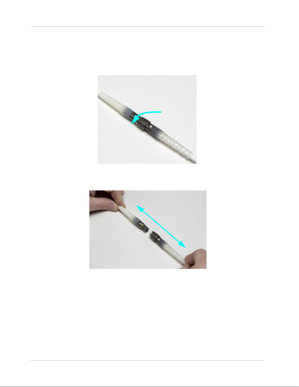
Chapter 2 System Operations
6. Disconnect your currently connected Modular Cable from the Pump Cable by rotating the locking nut
of the inline connector until the locking nut spins freely (
sound as you rotate the locking nut (this is normal). When the clicking sound has stopped, and
the locking nut spins freely, then pull the connectors apart as shown
Figure 2.48). You will hear a clicking
in Figure 2.49).
Figure 2.48 Rotate the Locking Nut
Figure 2.49 Pull the Connectors Apart
2-64
Page 94

Chapter 2 System Operations
7. Connect the replacement Modular Cable (which has already been connected to the replacement
System Controller) to the Pump Cable by aligning the white triangles and pushing the connectors
firmly together (see Figure 2.50).
Figure 2.50 Align the White Triangles
8. Rotate the locking nut of the Modular inline connector until the clicking sound has stopped and
the yellow line is hidden by the locking nut (see Figure 2.51).
Figure 2.51 Rotate the Locking Nut
9. Disconnect power and Modular Cable from the original System Controller and put the System
Controller into Sleep Mode or it will continue to alarm.
2-65
Page 95

Chapter 2 System Operations
Option 2: Replacing the Current Modular Cable with a Replacement Modular Cable
Before you begin, check that the replacement Modular Cable is available.
PROCEDURE:
1. If your current System Controller is alarming, silence the audio alarms for 2 minutes by pressing
the silence alarm button
2. To disconnect the current Modular Cable from the System Controller:
a. Orient the System Controller so the display is facing down.
b. Rotate the Safety Lock to the unlocked position (see Figure 2.52).
().
Figure 2.52 Unlock the Safety Lock
c. Unlock the Locking Nut on your currently connected Modular Cable from the Pump Cable by
rotating the locking nut of the inline connector until the locking nut spins freely (see Figure
). You will hear a clicking sound as you rotate the locking nut (this is normal). When the
2.53
clicking sound has stopped, and the locking nut spins freely, the locking nut has been unlocked.
Figure 2.53 Rotate the Locking Nut
2-66
Page 96

Chapter 2 System Operations
d. Firmly press the red button under the Safety Lock, while pulling the System Controller
Driveline Connector from the socket. Grasp the bend relief of the Driveline while removing it.
Do not pull on or bend the System Controller Driveline Connector (see Figure 2.54).
Figure 2.54 Grasp the Metal End and Remove the Driveline
CAUTION !
Do NOT insert a misaligned Driveline Cable Connector. When inserting the Driveline Cable Connector, do NOT orient the System Controller so the display is facing up.
3. To connect the replacement Modular Cable to the System Controller:
a. Align the WHITE arrow/alignment mark on the Driveline Cable Connector with the WHITE
arrow on the System Controller Driveline Connector (Figure 2.55).
Figure 2.55 Align the Arrows
b. Insert the Driveline Cable Connector into the socket, pressing firmly until it snaps into place.
Note: The Safety Lock cannot move to the locked position unless the Driveline is fully and prop-
erly inserted.
2-67
Page 97

Chapter 2 System Operations
4. Move the Safety Lock to the locked position, so that it covers the red button
(Figure 2.56).
Figure 2.56 Closing the Safety Lock
5. Pull apart the Modular inline Connector as shown in Figure 2.57.
2-68
Figure 2.57 Pull the Connectors Apart
Page 98

Chapter 2 System Operations
6. Connect the replacement Modular Cable (which has already been connected to the replacement
System Controller) to the Pump Cable by aligning the white triangles and pushing the connectors
firmly together (see Figure 2.58).
Figure 2.58 Align the White Triangles
7. Rotate the locking nut of the Modular inline connector until the clicking sound has stopped and
the yellow line is hidden by the locking nut (see Figure 2.59).
Figure 2.59 Rotate the Locking Nut
2-69
Page 99

POWERING THE SYSTEM
This section describes the various methods that can be used to power the HeartMate 3™ Left
Ventricular Assist System.
Power Overview - - - - - - - - - - - - - - - - - - - - - - - - - - 3-2
3
Using the Power Module - - - - - - - - - - - - - - - - - - - - - - 3-4
Using the Mobile Power Unit - - - - - - - - - - - - - - - - - - - - 3-34
Using HeartMate 14 Volt Lithium-Ion Batteries - - - - - - - - - - -3-51
Switching Power Sources - - - - - - - - - - - - - - - - - - - - - - 3-66
Battery Charger Overview - - - - - - - - - - - - - - - - - - - - - 3-73
Charging HeartMate Batteries - - - - - - - - - - - - - - - - - - - 3-80
Calibrating HeartMate Batteries - - - - - - - - - - - - - - - - - - 3-84
Using the Charger to Check Battery Power - - - - - - - - - - - - - 3-86
Care and Maintenance of the Battery Charger - - - - - - - - - - -3-87
3-1
Page 100

Power Overview
Power Module—The Power Module is intended for
use in the clinical setting when the patient requires
monitoring using the HeartMate Touch™
Communication System. The System Controller and
the Power Module are connected through the Power
Module patient cable. The cable transfers power from
the Power Module to the System Controller.
See page 3-4.
Mobile Power Unit—The Mobile Power Unit is for
home or clinical use when the patient does not require
monitoring using the HeartMate Touch Communication
System. The Mobile Power Unit is used when the patient
is indoors, stationary, or sleeping. The System Controller
and the Mobile Power Unit are connected through the
Mobile Power Unit patient cable. The cable transfers
power from the Mobile Power Unit to the System
Controller.
See page 3-51.
Chapter 3 Powering the System
3-2
 Loading...