

Page 1
Abbott
Pain
ManacementProvipeR
AIT
Technical
Service
Manual
For
use
with
13960 - All
13965 - All
ABBOTT
NORTH
USA
the
following
Codes
Codes
CHICAGO,
list
numbers:
LABORATORIES
IL
60064
430-85656-003
(Rev.
8/96)
Page 2

©Copyright
This
document
Laboratories
sale.
Any
whole
or
in
1996
retains
party
part
and
using
nor
disclose
the
all
the
this
subject
exclusive
document
it
to
others
matter
rights
accepts
Abbott
without
Laboratories
disclosed
of
dissemination,
it
in
the
herein
confidence,
written
are
consent
All
Proprietary
reproduction,
and
agrees
of
information.
not
Abbott
Rights
manufacture,
Laboratories.
Reserved
to
duplicate
Abbott
and
it
in
Page 3

List
of
Changes
Number
Part
Description
of
Change
Remove
Destroy
and
Pages
Insert
Change
Pages
430-85656-001
(Rev.
2/94)
430-85656-002
(Rev.
6/94)
430-85656-003
(Rev.
8/96)
Original
Second
and
figures;
global
Third
APM
issue.
issue.
winged
added
use.
issue.
II
pump
case
PVT
in
Added
back
international
Reformatted
information.
Form
Data
appropriate
screens
text
and
for
added
All
All
All
All
All
All
APM/APM
Technical
II
Service
Manual
8/96)
i
430-85656-003
(Rev.
Page 4

‘Changes
This
page
intentionally
left
blank.
430-85656-003
(Rev.
8/96)
APM/APM
II
Technical
Service
Manual
Page 5
Table
of
Contents
List
of
Changes
List
of
Figures
List
of
Tables
.
Section
Section
Section
Section
Introduction
1
1.1
Scope
1.2
APM
1.2.1
1.2.2
1.3
Conventions
Warranty
2
System
3
Theory
4
4.1
Front
4.2
Back
4.3
Motor
4.4
Latch
4.5
Motor
4.5.1
4.5.2
4.5.3
Optics
46
46.1
4.6.2
4.6.3
Printed
47
47.1
. . . . . . . . . . .
and
APM I Overview
Pump
APM
Operating
of
Operation
Case
Assembly
Case
Assembly
Frame
Assembly
Assembly
Motor
Motor
Motor
Assembly
Air-in-Line
Occlusion
Cartridge
Circuit
Circuit
4.7.1.1
4.7.1.2
4.7.1.3
4.7.1.4
4.7.1.5
4.71.6
.
Operation
and
APM
II
Differences
<
<
©
Manual
. .
Gearbox
Tachometer
Shaft
Installation
Board
Block
Microprocessor
Port
External
Alphanumeric
Power
Tachometer
.
Extension
Detection
Detection
Assembly
Diagram
Expander
Timer
Supply
.
・
.
.
. . . .
. . . . . .
.
. . .
.
.
and
Extemal
Display
.
Module
+.
+.
EPROM
+
.
1-1
.
1-2
.
1-3
1-5
.
4-2
.
4-2
.
4-2
.
4-3
.
4-4
.
4-4
.
4-4
.
4-6
.
4-6
.
4-6
.
4-6
.
4-8
.
4-8
.
・
4-8
4-10
4-10
4-10
4-10
4-10
APM/APM
II
Technical
Service
Manual
iii
430-85656-003
(Rev.
8/96)
Page 6
Contents
4.7.1.7
4.7.1.8.
471.9
4.7.1.10
4.7.1.11
4.7.2
4.7.2.1
4.7.2.2
47.23
4.7.2.4
4.7.2.5
4.7.2.6
4.7.2.7
47.28
MotorDrive
D/A
Converter
Optics
Serial
Isolated
Detailed
Circuit
Microprocessor
Address
Program
Port
External
LCD
D/A
Converter
Keypad
Battery
Low-Voltage
Tachometer
Motor
Air
and
Nonvolatile
RS-232
.
. .
Interface . .
EEPROM
Printer
Latch
Expander
Timer
Alphanumeric
Power
Drive
Occlusion
Serial
Interface
Description
(CPU)
.
Memory
.
.
.
.
.
.
Circuit
Detection
.
and
Speed
Memory
Data
.
.
. .
. . .
.
. . . .
.
.
.
.
.
.
.
.
.
.
.
.
.
Display
.
.
.
Detection
Interface
Module
.
.
.
.
. .
and
Reset
.
Control
.
. . . + +
.
.
.
.
.
. . . . .
. . .
.
. . . . .
.
.
.
.
.
.
.
.
.
.
.
.
.
.
.
M
.
.
.
.
.
.
.
κο
ne
Optics
for
Printer
.
. .
.
.
. .
4-11
.
.
.
.
. .
.
.
. . . 4-11
.
.
.
.
.
.
.
.
.
.
.
.
.
.
.
.
.
.
.
.
.
.
.
.
.
.
<
<
<
.
.
.
.
.
.
.
.
.
.
κο
κ +
ee
+
.
. .
.
. . .
+
+ +
a
4-11
. . 4-11
.
.
4-12
.
.
4-12
.
.
4-12
.
.
4-13
.
.
4-13
13
.
.
4-13
.
.
4-14
.
.
4-14
E)
15
416
416
4-19
420
420
Section
5
Maintenance
5.1
5.2
and
Service
Preventive
5.1.1
5.1.1.1
5.1.1.2
5.1.2
Performance
5.2.1
5.2.1.1
5.2.1.2
5.2.1.3
5.2.2
5.2.2.1
Maintenance
Inspecting
Pump
Accessories
Cleaningthe
Verification
Electrical
DelveyTest
Test
Equipment
Test
Display
Keypad
High-Speed
Low-Speed
Optics
SetClock
Printer
Initialize
Clear
Return
Equipment—
Tests
. .
Pump
the
Inspection
Inspection
Pump
Test
.
.
.
Check
and
Test
Test
NVRAM
Normal
to
.
.
Remote
Motor
Motor
.
.
.
.
Wet
Setup
Logs
.
Accessories
and
.
.
.
(PVT)
.
.
.
.
.
.
.
.
Bolus
Test
Test
.
.
.
.
.
.
.
.
.
Operating
.
.
Test
. .
.
.
.
.
.
.
.
.
.
. . .
.
.
.
.
.
.
.
.
.
.
.
C
Check
.
_.
.
.
.
.
.
.
.
.
.
.
.
.
.
.
.
Mode
.
.
.
.
.
. . .
.
.
.
.
.
.
.
.
.
.
.
.
.
.
.
.
.
.
.
woe
woe
|
.
.
.
.
.
.
.
.
.
.
.
.
.
.
.
.
.
.
.
.
.
.
.
.
.
.
.
.
. .
.
.
.
.
.
.
ee
ee
.
.
.
.
.
.
.
.
.
.
.
.
.
.
. . .
.
.
.
.
.
.
.
.
.
.
.
.
.
.
.
.
.
.
.
.
.
ew
ew
.
.
.
.
.
.
.
.
.
.
.
.
.
.
.
.
.
.
.
.
.
5-1
.
.
.
.
.
.
.
.
5-10
.
5-11
.
512
5-13
.
5-13
5.03
54
515
.
5-15
.
54
52
5-2
53
54
56
56
56
57
58
5-8
59
430-85656-003
(Rev.
8/96)
iv
APM/APM
Il
Technical
Service
Manual
Page 7
Contents
5.3
5.4
5.2.2.2
5.2.2.3
5.2.2.4
5.2.2.5
5.2.2.6
5.2.2.7
5.2.2.8
5.2.3
5.2.3.1
5.2.3.2
5.2.3.3
5.2.4
Bum-In
5.3.1
5.3.2
5.3.3
5.3.4
5.3.5 |
PVT
Data
Equipment — Dry
Test
Setup — Wet
Test
Setup — Dry
Pump
Programming
Delivery
Delivery
Delivery
Optional
Equipment
Test
Test
Test
Optics
Occlusion
Air-Detection
Troubleshooting
Test
Equipment
Setup
Test
Troubleshooting
Preparation
.
Procedure
Form
for
Use
Test
Test
Test
in
Progress
Results — Wet
Results — Dry
Test
Test
Test
.
.
Test
Test
5-15
5-15
5-15
5-16
5-16
5-17
5-18
5-19
5-19
5-19
5-19
5-19
5-20
5-20
5-20
5-21
5-22
5-23
5-24
Section 6 Troubleshooting
6.1
Technical
6.2
Troubleshooting
6.2.1
6.2.2
6.2.3
6.2.4
Section 7 Replaceable
7.1
Replaceable
7.2
Replacement
7.2.1
7.2.2
7.3
Pump
7.3.1
7.3.2
7.33
7.34
7.4
Pump
7.4.1
7.4.2
7.4.3
7.44
Assistance
Alerts
System
Malfunction
Troubleshooting
Parts
Parts
Safety
Required
Disassembly
Back
Case
Motor
PCB
Front
Reassembly
Hardware
Front
Motor
Back
Case
.
.......
Tables
and
Alarms
Error
Codes
Codes
and
Repairs.
Procedures
and
Equipment
Tools and
Procedure
Frame
Case
Procedure
Available
Case
and
PCB
Frame
.
.
Problems
. . .
Precautions
Materials
・
.
and Solutions
. . .
.
. .
.
6-1
.
6-1
.
6-2
.
6-4
.
6-6
.
.
・・・・
6-8
TA
TA
.
74
TA
.
7-2
.
7-2
.
72
„72
.
73
.
73
.
7-4
.
7-4
.
7-4
.
7-4
.
7-6
APM/APM
II
Technical
Service
Manual
v
430-85656-003
(Rev.
8/96)
Page 8
Contents
7.5
7.6
7.7
7.8
7.9
7.10
Back
Case
7.5.1
7.5.2
Optics
7.6.1
7.6.2
Motor
Assembly
7.7.1
7.7.2
Latch
Assembly
7.8.1
7.8.2
PCB
Assembly
7.9.4
7.9.2
7.9.3
7.9.3.1
7.9.3.2
7.9.3.3
7.9.3.4
7.9.3.5
Front
Case
7.10.1
7.10.2
Assembly
Component
Repair
Assembly
Procedure
Hardware
Repair
Hardware
Repair
Hardware
Repair
Components
Materials
Repair
Component
Repair
Procedure
Procedure
Procedure
Procedure
Beeper
Bolus
12-VDC
Lithium
LCD
Assembly
Procedure
Available
.
Available
.
.
Available
.
.
Available
.
Available
Required
.
Jack
Module
Available
. ・
Power
Battery
.
Jack
7-6
7-7
7-7
7-8
7-8
・
7-8
.
7-10
.
7-10
.
7-10
.
7-12
.
7-12
.
7-12
.
7-13
.
7-13
.
7-13
.
7-13
.
7-13
.
7-15
.
.
.
.
.
.
.
7-15
7-15
7-15
7-16
7-16
7-16
Section 8 Specifications
Section 9 Drawings
. .
soe
81
430-85656-003
(Rev.
8/96)
APM/APM
II
Technical
Service
Manual
Page 9

List
of
Figures
Figure
Figure
Figure
Figure
Figure
Figure
Figure
Figure
Figure
Figure
Figure
Figure
Figure
Figure
Figure
Figure
Figure
Figure
Figure
Figure
Figure
Figure
Figure
Figure
Figure
Figure
Figure
Figure
Figure
Figure
Figure
Figure
Figure
Figure
Figure
Figure
4-1.
Assemblies
4-2.
Motor
4-3.
Latch
4-4.
Motor
4-5.
Optics
4-6.
Circuit
5-1.
Cartridge
5-2.
Electrical
5-3.
Motor
5-4.
Optics
5-5.
Optics
5-6.
Delivery
7-1.
PCB
7-2.
Pump
7-3.
Back
7-4.
Back
7-5.
Optics
7-6.
Optics Wiring
7-7.
Optics
7-8.
Motor
7-9.
Motor
7-10.
Latch
7-11.
PCB
7-12.
LCD
7-13.
Front
7-14.
LCD
9-1,
APM
9-2,
APM
9-3,
APM
9-4,
APM
9-5,
APM
9-6,
APM
9-7,
APM
9-8,
APM
9-9,
APM
9-10,
APM
Frame
Assembly
Assembly
Assembly
Block
Channel
Test
Test
Test
Test
Test
Connections
Reassembly
Case
Case
Carrier
Assembly
Wiring
Assembly
Assembly
Back
Module
Case
Window
Analog
Microprocessor (CPU)
Power
PC
Board,
PC
Board,
II
Analog
II
Microprocessor
Il
Power
II
PC
Il
PC
Detail
Diagram
Detail
Setup
Display
Display
Block
Placement
Labeling
Assembly
Detail
Detail
to
Details
to
Motor
to
Detail
Mounted
Assembly
to
Front
Schematic
and
Miscellaneous
Front
Back
Schematic
and
Miscellaneous
Board,
Front Side
Board,
.
.
Diagram
.
Motor
Frame
Motor
.
on
Case
Side
Side
(CPU)
Back
Side
.
・
・
Frame
Frame
PCB
Schematic
Circuitry
Schematic
Circuitry
Schematic
Schematic
.
.
.
.
.
. +
.
.
ㆍ
ㆍ
fold-out
fold-out
fold-out
fold-out
fold-out
fold-out
fold-out
fold-out
fold-out
fold-out
drawing
drawing
drawing
drawing
drawing
drawing
drawing
drawing
drawing
drawing
41
4-2
4-3
4-5
4-7
4-9
5-5
5-7
5-9
5-11
5-12
5-17
7-3
.
7-5
7-6
7-7
7-8
7-9
・
7-9
7-10
7-11
7-12
7-14
7-15
7-16
7-17
APM/APM
II
Technical
Service
Manual
vii
430-85656-003
(Rev.
8/96)
Page 10

Figures
This
page
intentionally
left
blank.
430-85656-003
(Rev.
8/96)
Vi
APM/APM
II
Technical
Service
Manual
Page 11

|
List
of
Tables
Table
Table
Table
Table
Table
Table
Table
1-1.
APM
and
APM
1-2.
APM
and
APM
5-1.
Cleaning
6-1.
Alerts
6-2.
System
6-3.
Malfunction
6-4.
Troubleshooting . .
Solutions
and
Alarms
Error
Il
Hardware
Il
Software
. . . . .
.
. .
Codes
.
Codes . . .
. .
Differences . . . . . .
Differences
.
. .
.
.
.
.
.
.
.
. .
. . . .
. . .
. . . .
. . . .
. . . .
. .
. . .
. . .
. . .
. . . . .
. . . . . .
. . . .
. .
.
. .
1-3
. .
13
. .
54
6-2
65
.66
.
. .
6-8
APM/APM
Il
Technical
Service
Manual
ix
430-85656-003
(Rev.
8/96)
Page 12

This
page
intentionally
left
blank.
430-85656-003
(Rev.
8/96)
APM/APM
Il
Technical
Service
Manual
Page 13
Ἂ
Section
1
Introduction
11
Scope
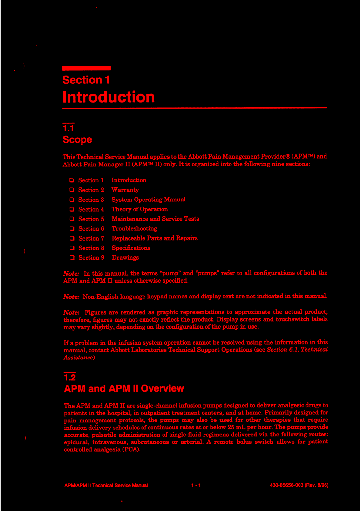
This
Technical
Abbott
Pain
O
Section 1 Introduction
Section 2 Warranty
Section 3 System
ロロ
Section 4 Theory
Section 5 Maintenance
ロロ
Section 6 Troubleshooting
Section 7 Replaceable
ロロ
Section 8 Specifications
Section 9 Drawings
ロロ
Service
Manager
Manual
II
(APM™
Operating
of
Operation
applies
II)
only.
Manual
and
Service
Parts
and
to
the
It is
Tests
Repairs
Abbott
Pain
organized
Management
into
the
following
Provider®
nine
sections:
(APM™)
and
Note:
APM
Note:
Note:
therefore,
may
If a problem
manual,
In
this
and
APM
Non-English
Figures
figures
vary
slightly,
in
contact
Assistance).
12
APM
The
patients
pain
infusion
accurate,
epidural,
controlled
and
APM
and
in
the
management
delivery
pulsatile
intravenous,
analgesia
manual,
II
unless
language
are
rendered
may
not
depending
the
infusion
Abbott
APM
APM
II
are
hospital,
protocols,
schedules
administration
(PCA).
the
terms
“pump”
otherwise
exactly
system
Laboratories
II
Overview
single-channel
in
outpatient
of
subcutaneous
specified.
keypad
as
graphic
reflect the
on
the
operation
the
pumps
continuous
of
and
“pumps”
names
configuration
Technical
single-fluid
and
display
representations
product.
cannot
Support
infusion
treatment
may
rates
or
arterial. A remote
pumps
centers,
also
at
or
regimens
of
the
be
be
below
Display
refer
to all
text
are
to
approximate
screens and
pump
in
resolved
Operations
designed
and
at
home.
used
for
other
25
mL
delivered
bolus
configurations
not
indicated
the
touchswitch
use.
using
the
information
(see
Section
to
per
switch
deliver
hour.
via
analgesic
Primarily
therapies
The
the
allows
of
both
in
this
manual.
actual
following
6.1,
Technical
designed
that
pumps
for
product;
drugs
the
labels
in
this
to
for
require
provide
routes:
patient
APM/APM
Il
Technical
Service
Manual
1-1
430-85656-003
(Rev.
8/96)
Page 14
Section
1,
Introduction
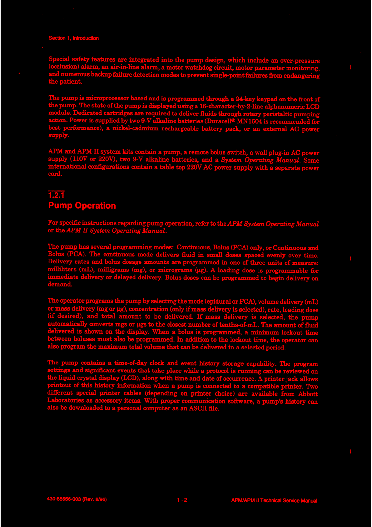
Special
(occlusion)
and
the
The
the
module.
action.
best
safety
alarm,
numerous
patient.
pump
is
microprocessor
pump.
The
Dedicated
Power
performance),
supply.
APM
and
APM
supply
(110V
international
cord.
1.2.1
Pump
For
or
the
Operation
specific
instructions
APM
II
features
backup
state
are
an
air-in-line
failure
of
the
pump
integrated
cartridges
is
supplied
II
system
or
220V),
by
two
a
nickel-cadmium
kits
two
configurations
regarding
System
Operating
alarm,
detection
based
and
is
displayed
are
required
9-V
alkaline
contain
9-V
alkaline
contain
a
pump
Manual.
into
the
pump
a
motor
watchdog
modes
is
to
prevent
programmed
using
to
deliver
batteries
rechargeable
a
pump,
a
remote
batteries,
table
top
220V AC
operation,
design,
through
a
16-character-by-2-line
fluids
(Duracell®
battery
and
refer
which
circuit,
single-point
motor
a
24-key
through
failures
rotary
MN1604
pack,
or
bolus
switch,
a
System
power
to
the
supply
APM
Operating
System
include
parameter
keypad
an
a
wall
with
an
over-pressure
monitoring,
from
endangering
on
the
alphanumeric
peristaltic
is
recommended
external
plug-in
pumping
AC
AC
Manual.
a
separate
Operating
Manual
front
LCD
for
power
power
Some
power
of
The
pump
has
Bolus
Delivery
milliliters
immediate
(PCA).
rates
(mL),
delivery
demand.
The
operator
or
mass
(if
desired),
automatically
delivered
between
also
program
The
pump
settings
the
liquid
printout
different
Laboratories
also
be
programs
delivery
is
shown
boluses
contains
and
significant
crystal
of
this
special
as
downloaded
several
The
continuous
and
bolus
milligrams
or
(mg
and
total
converts
on
must
the
maximum
display
history
printer
accessory
to
programming
dosage
(mg),
delayed
the
pump
or
ug),
concentration
amount
mgs
or
ugs
the
display.
also
be
programmed.
total
a
time-of-day
events
(LCD),
information
cables
items.
a
personal
modes:
mode
delivers
amounts
or
micrograms
delivery.
by
selecting
to
be
to
the
When
volume
clock
that
take
along
with
when
(depending
With
proper
computer
Continuous,
fluid
are
programmed
Bolus
doses
the
mode
(only
if
mass
delivered.
closest
that
and
place
a
bolus
In
time
a
pump
number
addition
can
be
event
while
and
on
printer
communication
as
an
ASCII
Bolus
in
small
(yg).
A
loading
can
be
(epidural
delivery
If
mass
of
tenths-of-mL.
is
programmed,
to
the
delivered
history
a
protocol
date
of
is
connected
choice)
file.
(PCA)
only,
doses
spaced
in
one
of
three
dose
programmed
or
PCA),
is
selected),
delivery
is
a
minimum
lockout
in
a
selected
storage
capability.
is
running
occurrence.
to
a
compatible
are
available
software,
or
Continuous
evenly
units
is
programmable
to
begin
volume
rate,
selected,
The
amount
time,
the
period.
can
be
A
printer
a
pump’s
over
of
measure:
delivery
delivery
loading
the
pump
of
lockout
operator
The
program
reviewed
jack
allows
printer.
from
Abbott
history
and
time.
for
on
(mL)
dose
fluid
time
can
on
Two
can
430-85656-003
(Rev.
8/96)
1-2
APM/APM
II
Technical
Service
Manual
Page 15
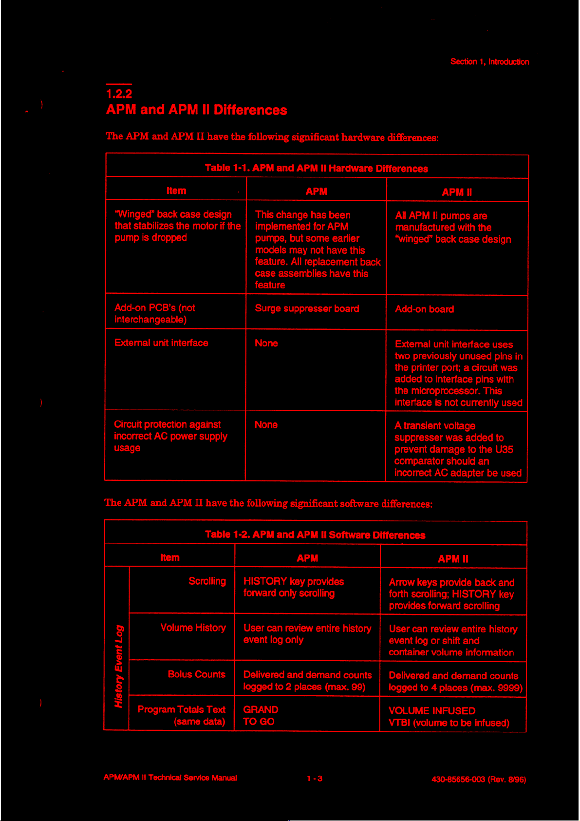
1.2.2
Section
1,
Introduction
APM
The
usage
and
APM
APM
and
Item
“Winged”
that
pump
Add-on
interchangeable)
External
Circuit
incorrect
back
stabilizes
is
dropped
PCB's
unit
protection
AC
II
APM
II
have
Table
case
design
the
motor
(not
interface
against
power
supply
Differences
the
following
1-1.
APM
and
This
change
if
the
|
implemented
pumps,
models
feature.
case
assemblies
feature
Surge
suppresser
None
None
significant
APM
Il
Hardware
APM
has
been
for
APM
but
some
earlier
may
not
have
All
replacement
have
board
hardware
Differences
this
back
this
differences:
APM
All
APM
II
pumps
manufactured
“winged”
Add-on
External
two
the
added
the
interface
A
transient
suppresser
prevent
comparator
incorrect
back
board
unit
interface
previously
printer
microprocessor.
port; a circuit
to
interface
is
not
voltage
was
damage
should
AC
adapter
Il
are
with
the
case
design
uses
unused
currently
pins with
This
added
to
the
an
be
pins
in
was
used
to
U35
used
The
APM
and
APM
II
have
the
Table
1-2.
Item
Scrolling | HISTORY
る
a
E
g
>
5
2
©
|
APM/APM
Volume
Bolus
Program
II
Technical
Totals
(same
Service
History | User
Counts | Delivered
Text
|
data) | TOGO
Manual
following
APM
and
forward
event
logged
only
can
log
to
GRAND
significant
APM
APM APM
key
provides
scrolling
review
only
and
demand
2
places
software
II
Software
entire
history | User
counts | Delivered
(max.
Differences
99)
differences:
Arrow
keys
forth
scrolling;
provides
can
event
log
container
logged
to
VOLUME
VTBI
(volume
provide
HISTORY
forward
review
or
volume
and
4
scrolling
entire
shift
and
information
demand
places
(max.
INFUSED
to
be
430-85656-003
back
and
key
history
counts
9999)
infused)
(Rev.
8/96)
Page 16
Section
1,
Introduction
2
E
Е
5
È
E
2
8
9
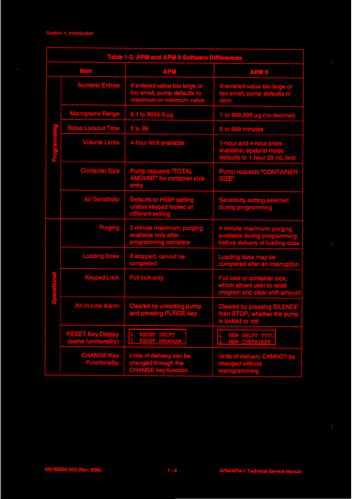
Item
Numeric
Micrograms
Bolus
RESET
Lockout
Volume
Container
Air
Loading
Keypad
Air-In-Line
(same
Key
functionality)
CHANGE
Functionality
Table
Entries
Range
Sensitivity
Purging
Display
Time
Limits
Size
Dose
Lock
Alarm
Key
|
|
|
|
|
|
|
|
|
|
|
|
|
1-2.
APM
If
entered
too
small,
maximum
0.1
to
9999.9
5to
99
4-hour
Pump
AMOUNT?”
entry
Defaults
unless
different
2
available
programming
If
completed
Full
Cleared
and
|1.
[2.
Units
changed
CHANGE
limit
requests
keypad
minute
stopped,
lock
pressing
RESET
RESET
of
and
APM
APM
value
pump
or
minimum
pg
available
“TOTAL
for
container
to
HIGH
locked
setting
maximum;
only
after
complete
cannot
only
by
unlocking
PURGE
SHIFT
PROGRAM
delivery
through
key
function
II
Software
too
large
defaults
value
setting
at
purging
be
pump
key
can
be
the
or
to
size
Differences
APM
If
entered
too
zero
1
to
5
to
1-hour
available;
defaults
Pump
SIZE”
Sensitivity
during
4
minute
available
before
Loading
completed
Full
which
program
Cleared
then
is
locked
1.
NEW
2.
NEW
Units
changed
reprogramming
value
small,
pump
999,999
999
minutes
and
4-hour
epidural
to
1-hour
requests
setting
programming
maximum;
during
delivery
dose
after
lock
or
container
allows
user
and
by
pressing
STOP,
of
whether
or
not
SHIFT
CONTAINER
delivery
without
too
large
defaults
ug
(no
decimal)
limits
mode
25
mL
“CONTAINER
selected
purging
programming
of
loading
may
be
an
interruption
lock,
to
reset
clear
shift
SILENCE
the
TOTL
CANNOT
amount
or
to
limit
dose
pump
be
430-85656-003
(Rev.
8/96)
1-4
APM/APM
II
Technical
Service
Manual
Page 17

13
Conventions
The
following
Q
Touchswitches
and
Q
Screen
beeps
conventions
[ENTER]
displays
sound
are
described
to
select a 100
reference
and
the
are
used
throughout
in
mL
in
the
INITIALIZE
all
caps
container
text
are
NVRAM
this
and
enclosed
size.”
in
all
OR
manual:
caps,
e.g.,
USE
ARROWS
in
brackets,
“When
Section
e.g.,
“Press
resetting
display
returns.”
1,
[1],
is
complete
Introduction
[0],
[0]
two
Throughout
information
this
manual,
as
follows:
WARNING:
A
warning
observe a warning
CAUTION: A caution
or
failure.
Note: A note
contains
highlights
warnings,
special
is
potentially
contains
information
cautions,
safety
emphasis
life
threatening.
information
that
and
and
must
that
could
helps
explain a concept
notes
be
prevent
are
used
observed
irreversible
or a procedure.
to
emphasize
at
all
equipment
times.
important
Failure
to
damage
APM/APM
II
Technical
Service
Manual
1-5
430-85656-003
(Rev.
8/96)
Page 18

Section
1,
Introduction
This page
intentionally
left
blank.
430-85656-003
(Rev.
8/96)
1-6
APM/APM
II
Technical
Service
Manual
Page 19
ἱ
_
Section
2
Warranty
Subject
warrants
defects
purchase.
for a particular
Purchaser’s
product.
cause
product,
or
properly
The
altered,
affect
or
to
that
in
material
Abbott
In
be
based
and
losses
or
packaged.
foregoing
or
its
stability
removed.
the
terms
the
makes
purpose,
exclusive
no
event
in
contract,
in
no
for
lost
warranty
used
other
or
and
product
and
remedy
shall
event
business,
than
reliability,
conditions
shall
conform
workmanship
no
other
warranties,
or
any
other
shall
Abbott’s
negligence,
shall
Abbott
revenue,
shall
be
void
in
accordance
or in
herein,
Abbott
to
under
normal
matter.
be,
at
Abbott’s
liability
be
arising
strict
liable
or
profits.
in
the
liability,
with
the
event
Laboratories,
Abbott’s
use
express
out
for
incidental,
Warranty
event
the
product
the
serial
standard
and
service
or
implied,
option,
of
any cause
tort,
or
otherwise)
product
product
manuals
or
lot
herein
referred
specifications
for a period
as
to
merchantability,
the
repair
or
replacement
whatsoever
exceed
consequential,
returned
has
been
misused,
so
as,
in
Abbott’s
number
has
been
and
of
one
(whether
the
or
special
to
Abbott
altered,
to
as
Abbott,
be
free
from
year
after
fitness
of
such
price
of
such
damages
must
damaged,
judgment,
defaced,
the
be
to
The foregoing
performs
been
approved
means
In
or
liability
of
whether
or
attempts
trained
spare
any
repair
providing
for
such
by an
any parts
acknowledged
is
not
an
authorized
warranty
authorized
parts.
or
service
the
actions
person
that
any
agent
shall
to
perform
For
for
or
has
person
also
be
any
major
representative
purposes
other
repair
of
than
or
service
inactions
been
trained
other
than
of
Abbott.
void
the
the
of
the
to
an
in
the
event
repair
or
of
Abbott
other
preceding
replacement
of
the
product,
person
perform
Abbott
performing
such
representative
any
person,
service
and
using
sentence,
of
accessory
Abbott
such
repair
including
on
the
Abbott
“major
items
shall
repair
or
service.
performing
the
product
without
documentation
repair
or
such
have
no
or
service,
It is
understood
repair
Purchaser,
having
and
other
service”
as
batteries.
responsibility
regardless
and
or
service
APM/APM
II
Technical
Service
Manual
2-1
430-85656-003
(Rev.
8/96)
Page 20

Section
2,
Warranty
This
page
intentionally
left
blank.
430-85656-003
(Rev. 8/96)
APM/APM
Il
Technical
Service
Manual
Page 21

PE
Section
3
System
A
System
binder’s
available,
Assistance).
Operating
pockets
contact
for
Operating
Manual
convenient
Abbott
is
included
reference.
Laboratories
Technical
with
every
If a copy
Manual
APM
and
APM
of
the
System
Support
Operations
II
kit.
Insert a copy
Operating
(see
Section
Manual
6.1,
Technical
in
is
this
not
APM/APM
II
Technical
Service
Manual
3-1
430-85656-003
(Rev.
8/96)
Page 22

Section
3,
System
Operating
Manual
This
page
intentionally
left
blank.
430-85656-003
(Rev.
8/96)
APM/APM
II
Technical
Service
Manual
Page 23
Section
4
Theory
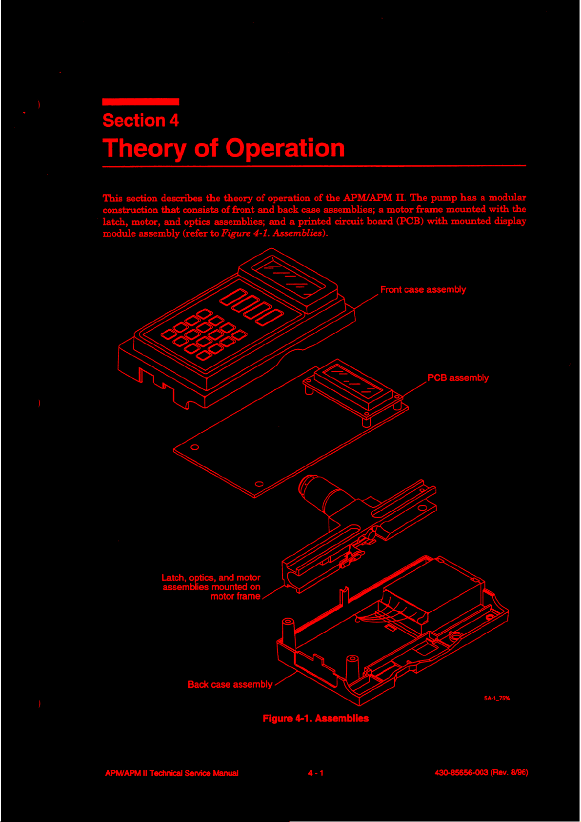
This
section
construction
latch,
motor,
module
describes
that
and
assembly
of
the
consists
optics
(refer
of
assemblies;
to
Figure
Operation
theory
of
front
4-1.
operation
and
back
case
and a printed
Assemblies).
of
the
assemblies; a motor frame
APM/APM
circuit
board
Front
II.
The
(PCB)
case
pump
has a modular
mounted
with
mounted
assembly
PCB
assembly
with
the
display
APM/APM
Latch,
optics,
assemblies
Back
II
Technical Service
and
motor
mounted
motor
frame.
case
assembly
Manual
on
Figure
4-1.
Assemblies
4-1
430-85656-003
(Rev.
8/96)
Page 24
Section
41
4,
Theory
of
Operation
Front
The
and
on
the
PCB
Operating
Case
front
case
EMI
protection
PCB.
The
by a ribbon
Manual
4.2
Back
The
door
of
spring
identified.
crimp terminal
43
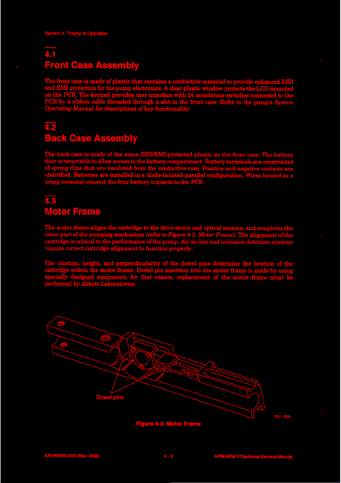
Motor
The
outer
cartridge
require
Case
back
case
is
removable
clips
Batteries
Frame
motor
frame
part
of
is
correct
the
critical
Assembly
is
made
of
for
the
keypad
cable
threaded
for
descriptions
Assembly
is
made
of
to
allow
that
are
insulated
are
installed
connect
pumping
cartridge
aligns
to
the
the
the
plastic
provides
the
access
that
pump
electronics. A clear
user
through a slot
of
same
to
the
from
in a diode-isolated
four
battery
cartridge
mechanism
performance
alignment
to
contains a conductive
plastic
interface
key
functionality.
ESD/EMI-protected
battery
the
with
in
the
compartment.
conductive
24
front
case.
parallel
contacts
to
the
(refer
of
the
function
to
drive
motor
to
Figure
pump.
properly.
the
PCB.
4-2.
Air-in-line
material
window
membrane
case.
Refer
plastic
as
Battery
Positive
configuration.
and
optical
Motor
Frame).
and
to
provide
protects
switches
to
the
the
front
terminals
and
negative
sensors,
The
occlusion
enhanced
the
LCD
connected
pump’s
case.
The
are
constructed
contacts
Wires
housed
and
completes
alignment
detection
ESD
mounted
to
the
System
battery
are
in
the
of
the
systems
a
The
location,
cartridge
specially
performed
height,
within
designed
by
the
Abbott
and
perpendicularity
motor
frame.
equipment;
Laboratories.
Dowel
pins
Dowel
for
Figure
that
of
the
pin
insertion
reason,
4-2.
Motor
dowel
replacement
into
Frame
pins
the
determine
motor
of
the
frame
motor
the
is
frame
location
made
by
must
5D-1_25%
of
the
using
be
430-85656-003
(Rev.
8/96)
4-2
APM/APM
Il
Technical
Service
Manual
Page 25
Cartridge
holding
tabs
Ejection
Opening
the
latch
Closing
the
latch
Section
4,
Ejector
Theory
pivot
of
pin
Operation
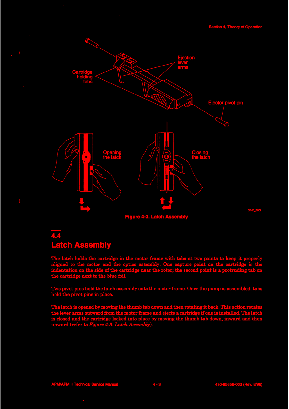
44
Latch
The
aligned
indentation
the
Two
hold
The
the lever
is
closed
upward
Assembly
latch
holds
to
cartridge
pivot
pins
the
pivot
latch
is
arms
and
(refer
y
m)
the
the
motor
on the
next
hold
pins
opened
outward
the
to
Figure
cartridge
and
side
of
the
to
the
blue
the
latch
in
place.
by
moving
from
cartridge
4-3.
Figure
in
the
the
optics
cartridge
foil.
assembly
the
the
motor
locked
Latch
4-3.
motor
assembly.
near
onto
thumb
into
tab
frame
place
Assembly).
+)
<<
Latch
Assembly
frame
the
with
One
the
rotor;
motor
frame.
down
and
and
ejects a cartridge
by
moving
tabs
capture
the
second
Once
then
rotating
the
thumb
at
two
points
point
point
the
it
if
tab
to
keep
on
the
cartridge
is a protruding
pump
is
assembled,
back.
This
one
is
installed.
down,
inward
it
properly
action
The
and
5D-2
50%
is
the
tab
on
tabs
rotates
latch
then
APM/APM
II
Technical
Service
Manual
4-3
430-85656-003
(Rev.
8/96)
Page 26
Section
as
4,
Theory
of
Operation
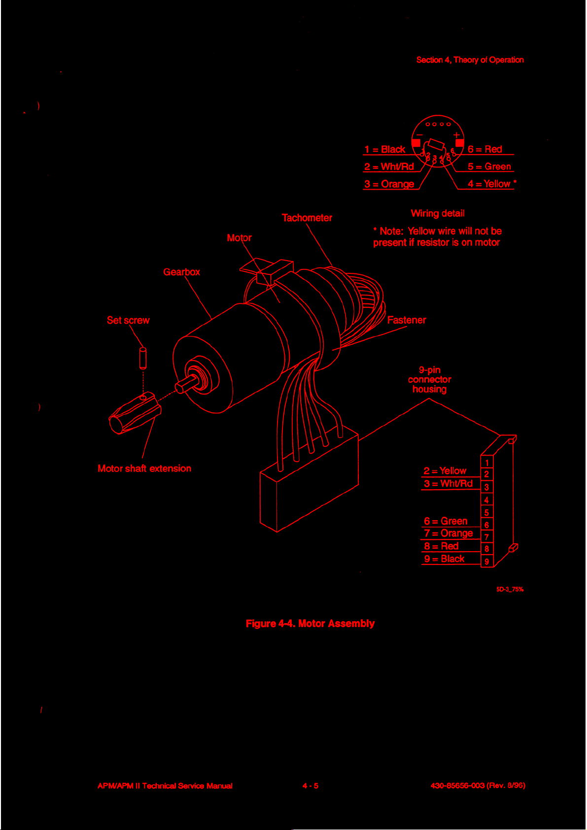
Motor
The motor
of a DC
into
(refer
All
motors
electrically
resistor
Assembly
assembly
brush-type,
the
motor.
to
Figure
are
interchangeable.
lead
4.5.1
Motor
The
torque
the
speeds,
Gearbox
motor
output
rotary
depending
gearbox
peristaltic
4.5.2
Motor
Tachometer
An
4-4.
tested
and
of
the
is
attached
iron-less
extension
Motor
at
the
yellow
contains a 128:1
motor
cartridge
on
the
core
is
Assembly).
the
factory
If a resistor
wire
to
the
pumping
rate
programmed.
to
the
motor frame
motor
with
attached
and a resistor
is
not
present.
gear
slower
speed,
mechanism.
with
attached
to
the
motor
may
is
installed,
reduction
higher torque
three
gearbox
shaft
or
may
the
to
transform
The
pump
locking
to
white/red
screws.
and
integral
mesh
with
not
be
added
the
relatively
requirements
drive
motor
wire
The
motor
tachometer
the
cartridge
to
make
is
attached
high
necessary
is
driven
consists
built
rotor
all
motors
to
speed,
to
drive
at
various
the
low
The
tachometer
the
gearbox.
180
degrees
rotation.
the
surface
phototransistor
As
the
on
whether
phototransistor
transitions
gearbox
of
approximately
delivered
The
of
rotation
Å side-by-side,
of
the
disk
rotates,
the
light
into
output
by
counting
shaft
45.3
Motor
The
motor
motor
shaft
Shaft
shaft
extension
consists
flat
receives
is
pulses
0.0876
of a disk
surface
and
light
disk,
such
the
the
phototransistor
or
dark
connected
that
correspond
going
to
milliliters
pulses.
Extension
extension
is
is
attached
mounted
of
the
disk
is
light
colored
emitting
that
the
reflected
area
of
the
to
an
electronic
the
cartridge
(mL).
cast
with
to
the
on
is
dark
(light
diode
light
beam
light
from
receives
disk
is
to
motor
completes
The
splines
motor
the
motor
colored
reflective)
(LED)
circuit
that
and
from
the
disk.
high
and
closest
that
turns.
pump’s
mesh
to
one
with a set
shaft
on
the
(not
light-reflective)
over
the
phototransistor
the
LED
shines
low
levels
of
the
phototransistor.
transforms
For
each
128
pulses,
full
turn,
resulting
software
with
keeps
the rotor
screw.
end
of
the
motor
over
remaining
pair
is
on
the
light
reflected,
The
the
light-to-dark-to-light
or
motor
in a fluid
track
of
volume
in
the
cartridge
opposite
approximately
180
degrees
mounted
disk,
and
depending
output
turns,
delivery
of
set.
over
the
of
the
the
fluid
The
of
430-85656-003
(Rev.
8/96)
4-4
APM/APM
II
Technical
Service
Manual
Page 27
Section
4,
Theory
of
Operation
Tachometer
*
present
Gearbox
Set
screw Fastener
=
i
i
レー
Motor
shaft
extension
Note:
Wiring
Yellow
if
detail
wire
resistor
is
will
9-pin
connector
housing
on
not
be
motor
APM/APM
Il
Technical
Service
Manual
Figure
4-4.
Motor
4-5
Assembly
430-85656-003
(Rev.
8/96)
Page 28
Section
46
4,
Theory
of
Operation
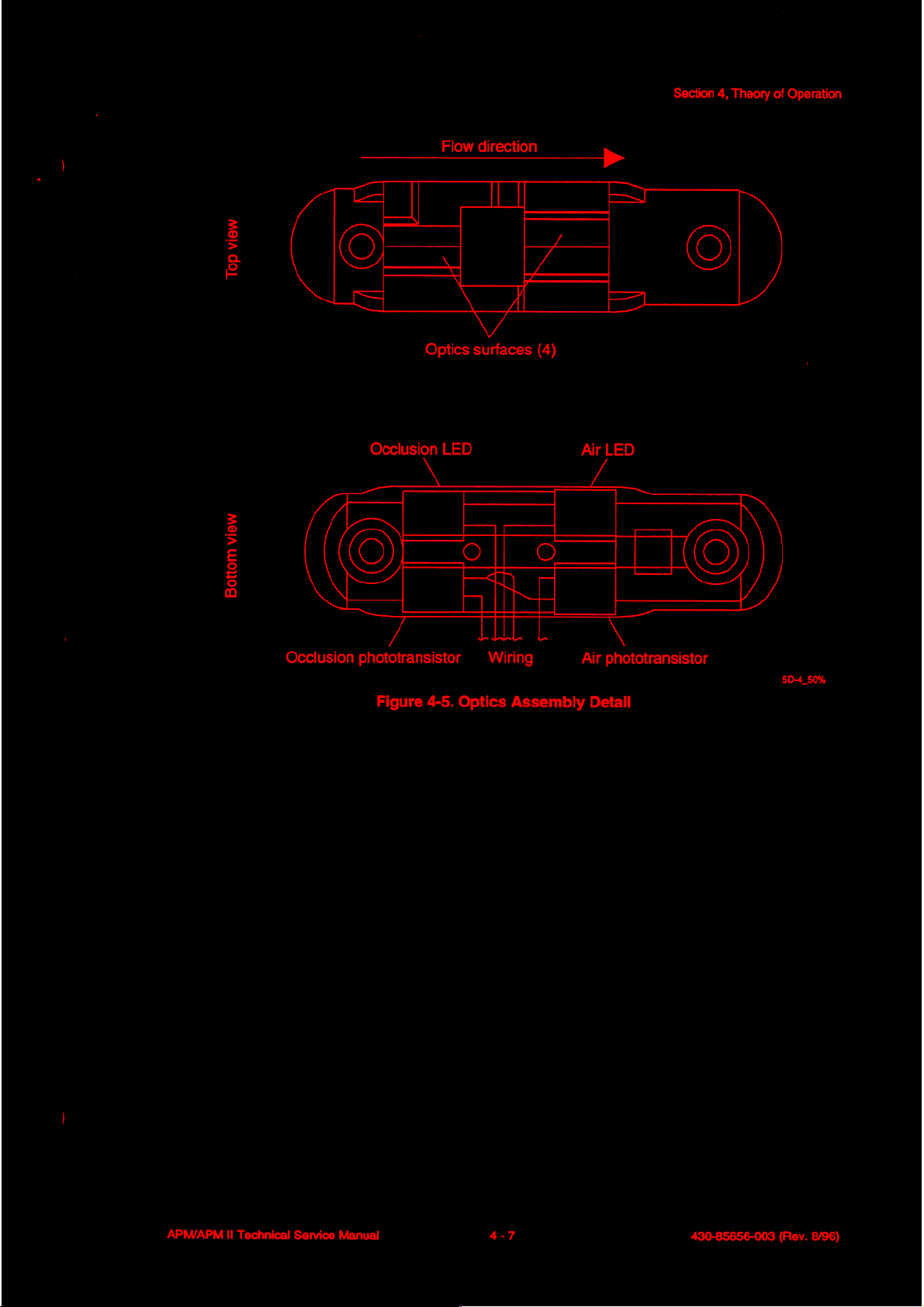
Optics
The
optics
of a carrier
Figure
occlusion
cartridge.
scratches,
so
that
The
LED/phototransistor
perform
>
6.1
Assembly
assembly
that
4-5.
Optics
conditions
In
order
which
the
sensing
the
following
Air-in-Line
When
phototransistor
is
sensing
from
phototransistor
air-in-line
fluid
present
chamber
the
is
present
in
the
LED
to
condition.
is
attached
holds
two
mounted
Assembly
by
reflecting
to
function
could
impede
chamber
of
pairs,
functions.
Detection
in
the
receives
sensing
makes
to
relatively
chamber
the
sensing
the
phototransistor.
go
further
into
to
the
motor
frame
LED/phototransistor
Detail).
correctly,
light
the
cartridge
The
LED/phototransistor
infrared
the
transmission,
cartridge
functioning
low
of
the
chamber
conduction.
aligns
it
diffuses
levels
cartridge,
Presence
with
light
beams
optics
and
properly
properly
light
of
light
however,
behave
In
summary,
two
screws.
pairs
and
off a sensing
surfaces
the
and
as a mirror,
of
must
cartridge
with
with
the
from
the
remains
the
air
thus
air-detection
The
optics
four optics
pairs
detect
chamber
be
kept
must
be
the optics
cartridge
LED,
thus
in
the
OFF
air
behind
reflecting
causes
phototransistor
assembly
surfaces
air-in-line
within
clean
and
inserted
detectors.
sensing
the
state.
the
much
the
correctly
chamber,
air-detection
When
surface
of
the
air-detection
consists
(refer
to
and
the
free
of
air
of
the
light
ON
=
4.6.2
Occlusion
When
phototransistor,
cartridge
cartridge-sensing
amount
surface
phototransistor
occlusion
no
of
becomes
Detection
occlusion
driving
rotation
the
balloon
less
drive
phototransistor
4.6.3
Cartridge
When
and
pair
displayed
no
the
activates a check
Installation
cartridge
pump
for
has
any
condition
it
further
causes
chamber.
reflective.
is
been
interruption
fluid
When
surface
and
installed
touches
causes
OFF = occlusion
placed
cartridge
is
present,
into
conduction.
pressure
the
the
An
occlusion condition
the
in
the
pump,
in
the
alarm.
of
the
light
to
balloon
plastic
transistor
condition.
or
run
mode,
Once
beam.
light
from
the
When a distal
expand a small
expands
on
the
to
go
the
cartridge
the
the
sufficiently
inside
therefore
occlusion-detection
pump
of
further
is
is
LED
reaches
occlusion
balloon
such
the
sensing
results
out
incorrectly
running,
in a decrease
of
conduction.
the
the
occlusion
condition
segment
that a significant
chamber,
installed
LED/phototransistor
occlusion
is
present,
within
the
in
occlusion
In
summary,
or
defective,
alarm
the
mirror
is
430-85656-003
(Rev.
8/96)
4-6
APM/APM
II
Technical
Service
Manual
Page 29
=
2
:
은
Flow
direction
©
Section
4,
Theory
(©)
of
Operation
$
i
る
a
(O=TZITG
Occlusion
Optics
Occlusion
phototransistor
Figure
LED
4-5.
Optics
surfaces
Wiring
Assembly
(4)
Air
LED
Air
phototransistor
Detail
5D-4
50%
APM/APM
II
Technical
Service
Manual
4-7
430-85656-003
(Rev.
8/96)
Page 30
Section
4,
47
Theory
of
Operation
Printed
4.7.1
Circuit
The
Block
Q
Q
Q
Q
Q
Q
A
particular
designator
Reference
Block
basic
electronic
Diagram).
Microprocessor
External
Port
Expander
External
Alphanumeric
Power
with a dash.
designators
Circuit
Diagram
system
EPROM
Timer
Display
Supply
pin
of a component
on
Board
consists
Module
For
example,
the
PCB
Assembly
of
the
following
is
identified
integrated
are
as
follows:
Q
Q
Q
Q
Q
Q
by
appending
circuit
components
Tachometer
Motor
D/A
Optics
Serial
Isolated
Drive
Converter
Interface
EEPROM
Printer
the pin
10,
pin 8 is
(refer
to
Interface
number
written
Figure
to
the
as
U10-8.
4-6.
Circuit
component
BT
ο
D
E
F
可
JP
L
LED
battery
capacitor
diode
enable
fuse
jack
jumper
inductor
light
emitting
test
471.1
Microprocessor
The
CMOS
is
configured
program
bits
of
of
general-purpose
The
major
the
microprocessor,
device
can
be
microprocessor,
in
memory
the
address/data
digital
has
its
unique
placed
in
two
the
point
diode
and
“expanded
(64KB
modules
x 8
buss
I/O
ports
and
address
different
External
with
internal
multiplexed”
bit).
The
into
address
used
to
of
the
circuit
are
thus
considered
and
is
low-power
EPROM
EEPROM,
address
bits
AO
interface
are
interfaced
addressed
modes
MOT
PCB
Q
R
SP
T
TP
U
x
counter/timers,
mode,
latch
demultiplexes
through
to
the
motor
to
be
memory
just
like
to
extend
motor
printed
transistor
resistor
speaker
transformer
test
point
integrated
crystal
which
utilizes
A7.
The
control
to
the
main
mapped.
external
battery
circuit
microprocessor
board
(or
beeper)
or
transducer
circuit
RAM,
an
the
multiplexed
and
monitoring
address
Each
memory.
life.
and
external
and
digital
The
microprocessor
A/D
converter,
EPROM
lower
eight
has a number
circuits.
data
busses
peripheral
for
of
430-85656-003
(Rev. 8/96)
4-8
APM/APM
Il
Technical
Service
Manual
Page 31

Section
4,
Theory
of
Operation
EMd
1X3
ee
O
101077
ο
0
ела
ebuey
ebuey
MOT
SH
미
E
Mnolo
40
pedolwS
SUld
HMd
HANAd
OL
<
16002
Jem
od
|
“J
A6
Kejdsig
200
JUIYO
6
MS
||
Mnolo
|
|
LIVE
=
L
[=
130
we
[>
HOZ
4-00
шо:
AUOO
va
®
suod
WOHd33
DIO
Notida
lgueS
?
+
sSeJPPV
ulpo9ed
St-ov
|
450%
2-00
Byeq\sseippy
py
tonuoo
pue
|
2
SL8V
„n
EST
IN
Jelubd
yoer
eoehelul
aos
Po
Seun
bod
Jeull
2-00
一
>
一
@
Pápa
|
Stay
SHod
sondo
sendo
(Θια
8
DINV)
n=
eoehelul
Jodeeg
£00
eoehelul
snog
AS
eolAep
leuJeix
引
sepuedxz
Hod
Kaızıy
eiouued
‘Ао
L
И
Им)
a
Pes
you
)
ぐー
ター
eoehelul
SHod
реле
snjog
yoer
APM/APM
Il
Technical
Service
Manual
Analog
Figure
Supply
4-6.
Voltage
Circuit
Block
Sense
Diagram
430-85656-003
6B-1.
(Rev.
100%
8/96)
Page 32

Section
4712
Port
4,
Theory
of
Expander
Operation
Because
to
ports.
because
is
interfaced
interfaced
4713
External
An
maintain
Because
2-megahertz
the
the entire
The
port
the
microprocessor
to
Timer
external
the
the
number
system,
to
these
timer
current
timer
(MHz)
microprocessor
without
backup
interrupting
battery
4714
Alphanumeric
The
alphanumeric
and
data
busses
module
board.
contains
of
the
expander
the
system
ports.
is
utilized
time
operates
crystal,
to
greatly
the
when
the
Display
display
and
provides
all
I/O
port
lines
available
port
expander
essentially
is
configured
via the
and
on
the
extend
external
replaces
port
(in
addition
date
and
only a 32-kilohertz
timer
battery
timer.
5.0 V supply
on
was added
port
in
the
expander
to
to
generate
can
operate
life.
The
The
timer
provided
the
expanded
the
by
Module
is a 16-character-by-2-line
programming
interface
and
LCD
and
operating
driver
microprocessor
to
increase
lines
that
are
the
lost
multiplexed
ports.
timers
timing
(kHz)
at
much
The
remote
internal
interrupts
crystal,
lower
microprocessor
automatically
the
power
LCD
circuit
module
status
circuitry
built
is
not
sufficient
total
number
to
address
mode.
The
bolus
switch
to
the
microprocessor)
to
the
and
the
microprocessor
standby
can
be
put
switches
is
that
over
no
longer
interfaces
information
in
on
its
own
to
interface
of
available
and
data
24-key
jack
keypad
is
microprocessor.
currents
in
the
to
than
stop
an
internal
mode
present.
to
the
address
to
the
user.
printed
circuit
lines
also
to
on
a
the
The
4715
Power
The
power-fail
operating
power-switching
these
Supply
power
low-duty
circuit
interrupts
conditions.
cycle
4716
Tachometer
Motor
circuit.
allows
speed
The
power
is
circuit
to
provides
and
Because
circuit
was
use
circuits
indicated
interfaces
be
pulsed
regulated
reset
signals
some
added
only
to
the
microprocessor
to
either optical
on
and
off
5.0 V to
of
the
to
allow
when
to
minimize
most
of
the
to
the
microprocessor
circuitry
the
microprocessor
needed.
via a tachometer
or
magnetic
power
devices
is
in
the
utilized
to
cause
Hall-effect
consumption.
system
under
only part
and
certain
power
also
low-voltage
of
the
to
be
and a tachometer
type
tachometers
generates
time,
the
applied
to
interface
and
430-85656-003
(Rev.
8/96)
4-10
APM/APM
II
Technical
Service
Manual
Page 33

4.7.1.7
Motor
The
the
DC
is
Switching
battery
Drive
motor
D/A
drive
driven
voltage
outputs
drive
circuit
under
to
the
permanent
with a relatively
regulator
to a lower
allows
microprocessor
DC-to-DC
voltage
the
magnet
smooth,
step-down
to
motor
DC
motor.
slowly
the
to
be
driven
control.
Because
varying
converter
motor.
The
at
various
motor
the
drive
level
to
techniques
input
driver
provides
signal
maximize
speeds
are
Section
4,
as
analog
is
not
pulsed,
brush
utilized
and
Theory
of
Operation
determined
(not
pulsed)
the
gearbox
to
convert
by
motor
life.
the
Motor
current
to
speed
information
cause
shutdown
is
maintained
4718
D/A
Converter
To
allow
the
motor
set
the
speed references
analog outputs
dose)
or
low
rates,
不
7.15
Optics
The
and
microprocessor
on
4.7.1.10
Serial
Interface
optics
air-detection
occlusion-detection
and
off
to
minimize
EEPROM
to
indicate
of
the
motor
to
operate
for
to
provide a high
respectively.
and
optics.
control
over
power
relatively
at
the
occlusion-detection
the
consumption.
the
motor
to
prevent
various
motor
and
low
Both
trip
constant
speed.
runaway
output
drive
range
air
and
points.
The
by a servo
The
speeds, a two-channel,
circuit.
of
motor
circuits
occlusion
optics
motor
in
the
The
interface
system
event
speed
interface
circuits
that
drive
of
converter
control,
circuit
any
have been
allows
utilizes
contains
single
D/A
provides
for
to
the
the
motor
safety
component
converter
two
high
(bolus
separate
modified
optics
voltage
independent
air-detection
to
circuits
failure.
is
used
or
loading
to
allow
be
pulsed
and
to
A
serial
EEPROM
storage
of
4.7.1.11
Isolated
An
optically
circuit
and
an
APM/APM
has
output
II
interfaces
history
Printer
provision
Technical Service
data
Interface
isolated
for
control
that
RS-232
line.
can
one
Manual
to
the
be
circuit
serial
data
microprocessor
reviewed
interfaces
line
on
in,
4-11
the
the
one
via
port
lines
display
microprocessor
serial
or
data
printed
line out,
and
port
is
utilized
out.
lines
to a connector.
and
an
input
430-85656-003
for
nonvolatile
control
(Rev.
The
line
8/96)
Page 34

Section
4,
Theory
of
Operation
4.7.2
Detailed
Refer
to
Q
Figure
Q
Figure
Q
Figure
Q
Figure
Q
Figure
Q
Figure
Q
Figure
Q
Figure
Q
Figure
Q
Figure
4721
Microprocessor
Circuit
Section
9-1.
9-2.
9-3.
9-4.
9-5.
9-6.
9-7.
9-8.
9-9.
9-10.
9,
APM
APM
APM
APM
APM
APM
APM
APM
APM
Description
Drawings,
Analog
Microprocessor
Power
PC
Board,
PC
Board,
II
Analog
II
Microprocessor
II
Power
II
PC
Board,
APM
II PC
Board,
(CPU)
for
the
following
Schematic
and
Miscellaneous
Front
Back
Schematic
and
Miscellaneous
Front
Back
(CPU)
Side
Side
(CPU)
Side
Side
fold-out
Schematic
Circuitry
Schematic
Circuitry
schematics
Schematic
Schematic
and
PCB
drawings:
The
heart
of
the
microprocessor
at
MODA
as
“Vs,”
modes
ground.
and
which
can
be
initiated
For
troubleshooting
TP2.
The
oscillator
parallel
microprocessor
the single
acts
correct
even
circuit
to
limit
phase
very
is
extremely
resonant
inverter
the
shift
small
4722
Address
The
multiplexed
and
the
latch
through
to
the G input
Latch
upper
U3
demultiplexes
A/D7.
CPU
system
is
configured
MODB
instructs
circuit
bus
address
The
of
inputs.
at
is
formed
type
speed
in
the
drive
energy
for
stable
amounts
critical.
address/data
lines
the
address
U3.
is
the
in
the
expanded
When
the
microprocessor
reset
by
pulling
the
address
via
operating
is
1/4
the
68HC11
of
stray
lower
latch
somewhere
to
the
oscillation
capacitance
lines
(A8
through
address
U3
Motorola
multiplexed
the
microprocessor
to
one
or
decoder
X1,
R13, R11,
at a crystal
crystal
relatively
(A/DO
is
frequency,
low
to
occur.
from
through
A15)
lines
clocked
(A0
68HC11E1FN
is
go
into
the
both
of
these
circuit,
and
C1.
frequency
or
in
the
linear
are
by
power
Since
the
capacity
this
other
components
A/D7)
available
through
U2
CMOS
mode
through
reset,
both
expanded
lines
initiate
The
oscillator
of
500
kHz.
region
circuit
are
available
from
A7)
from
address
microprocessor
the
pull-up
of
these
inputs
multiplexed
low
with a clip
mode B testing
is a single
2.00
Resistor
of
operation.
X1.
C1
is
especially
or
runs,
PBO
through
the
multiplexed
strobe
MHz.
on
(AS)
R13
helps
the
PCO
output
The
to
(U2).
The
connections
are
read
mode.
lead
by
serves
Resistor
establish
vulnerable
layout
through
PB7.
Other
to
digital
grounding
inverter
resulting
to
bias
R11
the
of
this
PC7,
Address
lines
A/DO
connected
to
430-85656-003
(Rev.
8/96)
4-12
APM/APM
II
Technical
Service
Manual
Page 35

4.7.2.3
Program
Memory
Section
4,
Theory
of
Operation
Program
for
to
cause
Thus
memory
U4
is
accomplished
the
U4
3724
Port
Expander
The
address
through
software
8-bit
connected
A15.
reprograms
ports
4725
External
U9,
U7C,
U8B,
O8XX
H,
where
the
total
address
proper
via
maintain
supply
the
AO
own
timing
U8C
drops
U5
ground
to
A4
address
and
U4
is
chip
decode
Following
to
the
to
the
Timer
are
U8D.
the
U5
below
circuit
are
connected
latch
is
stored
chip
enable
selected
for
system
same
and
associated
U7
defines
to
thus
generated
1M
power
a
clocked
in
a
by
U17A
input
for
any
the
port
reset,
U1
to
an
as
PCO
reset
as
inverters
the
be
in
the
by
pull-up
consumption
preset
to
the
directly
by
threshold,
negative
the
64KB
x
8
and
U14F.
to
pulse
read
operation
expander
U1
is
addressed
address
through
U2,
so
that
lower
two
range
summing
resistors
low
side
to
the
U2
address
bit
CMOS
Any
address
low
when
whose
U1
consists
as
of
02XX,
PC7
decode
nibbles
of
0800
the
such
when
U5
of
multiplexed
03XX,
and
both
ICs
the
address
to
H
to
E
clock
as
R17,
the
contains
the
3-V
strobe
EPROM
E
12XX, 13XX,
PBO
are
be
081F
5.0-V
internal
lithium
address/data
(AS)
of
1000
clock
address
of
U14C
etc.
through
reset
for
in
the
H.
from
U2
R15,
supply
connected
(27C512),
and
The
simultaneously.
the
range
The
and
circuits
backup
H
Read
is
1000
and
16XX,
port
PB7.
timer.
RD
with
R16
is
bus,
U4.
or
greater
are
H
internal
17XX
expander
Note
U9
of
00
H
to
and
WR
read
or
pull
not
present.
that
battery
because
to
the
The
address
enables
simultaneously
through
decoding
that
decodes
1F
control
write,
up
automatically
BT1.
U5
ALE
decoding
gate
FFFF
from
H,
etc.,
but
adds
two
reset
on
the
address
H.
U8
decodes
lines
respectively,
control
When
U5
lines
the
Address
contains
input.
U7B
high.
H.
A12
the
extra
Ul
is
with
to
5.0-V
switch
lines
its
The
oscillator
capacitor
similar
consumption
components
microprocessor
to
to
the
4726
LCD
Alphanumeric
U6
and
U7A
from
U9
with
ANDed
from
decode,
configured
display
to
shut
with
U8A.
glitch-free
—
allow
off.
The
to
DB4
these
circuit
allow
is
or
for
U5
trimming
microprocessor
much
lower.
traces.
can
The
be
generated
Display
perform
the
Al
operate
to
lines
decode
via
U7A
ANDing
enable
in
DB7.
to
address
and
of
a
U12
be
consists
the
The
effective
of
time
oscillator
U5
through
Module
decoding
of
XX20
to
XX23
E
clock,
E
clock
with
pulses
4-bit
serves
effectively
are
mode
as
components
base
for
minimal
(U2),
except
oscillator
ground
for
the
presented
with
a
switch
disconnected
pin
the
to
final
the
only
circuit
for
the
6
of
U5
LCD
result
resultant
address
to
the
for
the
X2,
C7
and
C8.
C7
is
an
timing
that
is
also
U5
oscillator
via
an
module.
in
a
decode
decode
decode
the
enable
upper
from
four
bidirectional-directional
the
error.
the
frequency
susceptible
is
open
drain
U6
combines
of
0820
is
0820
assures
display
data
bits
display
when
The
and
to
5.0
У.
output
to
to
that
only
input.
being
the
adjustable
oscillator
resultant
coupling
Interrupts
pulled
the
0823.
0821
AD4
from
up
decode
When
to
the
stable
The
display
connected
to
AD7
display
trimmer
circuit
power
other
to
the
by
R12.
of
08XX
this
display
address
to
the
lines
power
is
is
is
is
APM/APM
Il
Technical
Service
Manual
4-13
430-85656-003
(Rev.
8/96)
Page 36

Section
4,
Theory
of
Operation
Display
minimize
PWR
cause
to
D7;
display
on,
These
and
the
and
the
off.
power
ON)
the
display
C30,
are
delay
delays
4727
D/A
Converter
Address
described
for
converter
The
that
decoding
the
DAC.
WR
input
clocks
4.7.2.8
Keypad
is
shut
5.0-V drain
from
the
microprocessor.
control
above,
to
turn
R50,
either
circuits
are
except
lines
and
at 0 V
necessary
for
Address
is
addressed,
clocks
the
WR
of
off
by
current.
to
the
display
the
display’s
D6)
function
or
floating
allow Vad
to
the
D/A
that
Al
bit
AO
thus
0822
the
DAC
the
timer.
the
microprocessor
Power
prevent
to
the
When
to
go
Vad
power
as
time-delay
before
to
be
applied
latchup
converter
is
used
in
Vad
determines
addresses
when
WRITE
when
display
power
to 0
is
the
place
whether
section A and
can
to
the
V.
Transistor
on
and
circuits
to
the
display
to
the
in
the
same
of
Al
the A or B section
and E clock
the
be
turned
display
off.
The
to
display
display
as
address
to
give
0823
are
display
Q7 functions
RC
assure
is
shut
before
when
the
is
on
and
is
shut
and
diode
that
off.
signal
switching
decoding
resultant
addresses
both
high,
not
needed
off
via
off,
gates
as
the
networks
all
signal
When
Vad
lines
for
address
of
the
two-channel
section B of
with
in
PB5
(DISPLAY
U13A
power
(C29,
lines
is
turned
become
display
the
display
of
the
same
order
to
U13C
switch
R49,
to
back
active.
power
0822-23
D/A
the
DAC.
signal
to
the
on
as
The
keypad
PB4. The
by
input
actual
same
bolus
potential
Pull-down
pressed
microprocessor
row
1,
interrupt
from
off
cause
U15B
jack.
R121,
pickup
microprocessor
Column 4 drive
the
low
interfaces
four
ports
column
row
be
switch
keypad
resistors
and
provided
is
used
to
on.
an
interrupt
and
U15C
R56,
from
state
columns
PC05.
of
pressed
interface,
the
U13D
the
when
to
of
the
Diodes
the
keypad
simultaneously.
but
expansion.
R31
to
column
on
IRQ
when
that
the
to
allow
ors
the
to
the
microprocessor
are
added
R55,
and
remote
port
is
inputs.
pulsed
U15C
bolus
simultaneously.
the
microprocessor
keypad
D20
for
also
R34, R40,
drive
the
appropriate
the
microprocessor
keyboard-generated
as
C34
U15C
is
in
are
driven
through
isolation
PB4
serves
interface
serve
switch.
its
as a spare
and
is
pulsed.
interrupt
column
buffers
as a low-pass
U15B
will
pulse
normally
D23
that
R57
on
Diode
via
port
expander
by
output
are
in
series
prevents
is
an
keep
U15A
is
enabled
drive
to
be
IRQ
to
and C further
high
D4
low-output
conflicts
extra
output
column
the
allows
via
for
removed
interrupt
for
either a keyboard
either
filter
whenever
prevents
state.
ports
ports
PB03,
between
should
used currently
drive
for a fifth
input
ports
generation
PB7
and
the
on/off
from
stop
with
the
the
bolus
to
attenuate
isolate
the
U15C
PCO
and
the
the
column
two
at
a 0
of
an
the
on/off
key
is
mode
interrupt
or a timer
switch
potential
any
ESD
bolus
switch
from
holding
to
PC5
and
PBO
six
rows
are
drive
and
or
more
keys
in
only
to
drive
column
level until a key
high.
to
or
to
interrupt
key
is
pressed
The
keyboard
turn
the
from
the
interrupt.
the
remote
noise
or
noise
is
pressed
tow 4 drive
allow
to
system
timer
or
from
to
read
the
the
the
for
is
the
in
to
bolus
ESD
the
and
in
430-85656-003
(Rev.
8/96)
4-14
APM/APM
Il
Technical
Service
Manual
Page 37

47.29
Battery
Input
diodes
polarity
two
with a depleted
ESR
motor
attenuator
voltage.
in a 5.0-V
voltage
Power
power
batteries
filtering
from
D1
and
and
also
drive
circuits,
and low-pass
The
attenuator
input
fluctuations
are
against
Circuit
the
two
D2.
These
prevent
at
different
battery).
fluctuations
tachometer
attenuates
to
the
A/D
so
that
9-V
alkaline
diodes
one
battery from
states
These
filter
to
(maximum
the
batteries
prevent
circuit
loading
of
depletion
are
Schottky
on
the
or
optics
allow
diodes
V_PWR
circuits,
the
microprocessor’s
by a factor
input
range).
microprocessor
or
rechargeable
damage
and
line
of
0.3651
down
for
or
in
or
voltages
minimal
caused
display
so
that a 13.7-V
The
low-pass
reads a sample
battery
the
event
shorting
(e.g., a new
voltage
by
such
LCD.
A/D
port
of
the
Section
pack
of
an
out
the
battery
drop.
loads
as
R53, R54,
PE6
to
supply
filter
serves
average
4,
Theory
is
routed
incorrect
other
in
being
C20
provides
pulses
and
C65
sample
the
voltage
to
average
battery
of
Operation
through
battery
case
the
paired
low
from
the
form
an
supply
results
out
voltage.
Power
D5
power
will
PE6,
The
provides
provides
can
also
provide
isolation
supply
override
the
microprocessor
supply
voltage
additional
energy
voltage
the
microprocessor
reset
circuitry.
then
reapplied
47210
Low-Voltage
The
dual
low-voltage
interrupt
approximately
voltage
U16.
the
at
O1
high,
filtering
low
the
attempt
At
very
to
approximately
to
the
down
to a voltage
C24
provides
microprocessor.
during
causing
transitions.
transistor
against
to
the
microprocessor
microprocessor
to
run
low
supply
reach
the
V_PWR
between
(typically
batteries
when
can
is
regulated
higher
storage
to
store
C32
limits
to
prevent
frequency
and a 5.0-V
certain
the
false
Detection
detect
microprocessor.
3.3
V.
R25, R26,
to
filtering
R58
noise
crystal
at
very
voltages,
the
adds
When
93
pulses
low
Vbe
cut-in
to
to
down
oscillator
supply
line
from
the
battery
12
V)
is
it is
determine
down
regulation and
bus
information
rate
of
change
resets
and
IC
Reset
U16
from
functions
The
and
R27
be
compared
prevent
hysteresis
the
5.0-V
be
driven
causing
to a supply
stops
voltages
the
U16
output
voltage
an
voltage
higher
plugged
when
to
5.0 V by
external
than
in
the
power
and
the
external
the
battery
and
functioning. By
APM
is
operating
the
micropower
noise
loss-delay
in
of
being
reset
is
in
the
its
internal
5.0-V
issued
as
both a microprocessor
generated
EEPROM
supply
by
when
form a voltage divider
with
the
approximately
any
noise
pulses
to
the
sensed
supply
on,
which
inadvertent
voltage
running
and
cause
O1
floats
of
Q3,
or
approximately
on
input
line
is
below
drives
RESET
resets.
of
approximately
to
assure
corruption
high,
supply
power
voltage,
on
voltage
suppression
event
of
power
voltage
when
U16.
the
that
attenuates
1.3-V
the
5.0-V
VS1
to
prevent
approximately
low.
It
is
important
that
the
ofits
internal
resulting
0.6
V.
coupled
to
supply.
thus
the
sampling
external
D5.
Normally,
the
(AC)
regulator
on
the
5.0-V
failure
prior
to
being
power
reset
5.0-V
is
and a power
supply
the
internal
supply
line
from
ringing
3.3 V,
C37
provides
that
RESET
1.0
V,
or
the
microprocessor
CONFIG
in
Q3
remaining
D1,
D2,
power
supply
voltage
power.
U11. C21
bus.
to
allow
reset
by
removed
is
less
5.0-V
supply
reference
resetting
of
the
output
O1
will
additional
be
point
where
does
register.
on
and
the
at
C22
the
the
and
fail
than
of
be
held
not
down
Signal V BAT
and
R23,
R24
LOW
function
hysteresis. V BAT
microprocessor
batteries
APM/APM
Il
that
and
no
Technical
power
goes
LOW
the
Service
low
as
voltage
is
connected
supply
supply
Manual
when
dividers,
power
is
connected
the V BATT
and
to
the
is
failing,
to
the
4-15
voltage
C23
drops
functions
as a filter,
microprocessor’s
for
example
when
pump.
below
XIRQ
approximately 6 V.
while
R120
input
to
indicate
the
user
removes
430-85656-003
R59,
provides
to
the
the
9-V
(Rev.
8/96)
Page 38

Section
4,
Theory
of
Operation
4.7.2.11
Tachometer
The
tachometer
provides a continuous
power
supplied
Hall-effect
to
pin 6 and
is
connected
the
operating
reference
below
encoder
high
Shortly
the
will
for
this
selected
is
pulled
approximately
after
OUT
pin
be
high
(encoder)
to
type
encoder.
cathode
to
pin 4 and
frequency
operation
up
Vpp
pulses
will
be
for
the
the
to
set
by
every 4 ms,
low
next
47212
Motor
Drive
and
Speed
circuit
square
encoder
When
ground.
the
Hall-effect
of
U18.
of
U18
point
R44
and
high,
for
the
cycle.
consists
wave
output
is
not
continuous.
the
LED
When
the
R45, R47,
at
its
SET
of
operation.
connected
turns
U18
samples
next
cycle.
Control
of
U18
to
be
This
tachometer
Hall-effect
supply
to
pin 5 (+5.0
and
R48
input
(pin
The
collector
to
the
Vin
on
transistor
Vin.
If
If
Vin
is
and associated
read
by
the
microprocessor
circuit
is
sensor
to
allows
be
used,
is
used,
V).
R46
form a voltage
3).
R48
sets a hysteresis
output
(pin
2)
of
U18.
A8,
and
drives
Vin
is
higher
lower
than
the
use
the
the
and
divider
from
the
The
than
the
SET
components.
This
even
of
either
an
LED
anode
is
Hall-effect
C28
to
sensor
together
establish a set-point
level
(A)
phototransistor
Vppoutput
the
tachometer
SET
input
input
minus
of
plus
A,
circuit
though
optical
the
or
connected
ground
determine
above
and
in
the
U18
pulses
LED
ON.
A,
then
then
OUT
a
D/A
Converter
The
current
which
U2I1C
converter
Motor
The
by
the
since the
set-point
to
set-point
the
motor
amount
Current
Current
work
are
directly
produces
Speed
voltage
the
motor
motor
can
motor
speed
determine
speed
applied
current increases due
as
the
Sensing
sensing
as a current
sensed
40, as
low-pass
voltage).
determined
filter
proportional
by the
of
motor
motor
current
Output
outputs
in
conjunction
proportional
an
applied
plus
to
the
be
determined
constant
is
established
the
high-speed
is
constantly
motor
voltage
resulting
for
sensing
Noninverting
by
to
smooth
to
an
average
speed
controller
under
of
the
output
the
motor
IR
drop
and
to
increase
the
motor
resistor
the
ratio
out
motor
software
D/A
converter
with
internal
to
the
voltage
at
any
across
from
the
motor
by
the
range
compared
attempt
to
increased
in
is
accomplished
to
convert
operational
of
R61/R60.
fast
fluctuations
current
is
also
control.
U20
resistors
value
written
of
5.0
V.
given
time
the
motor
motor
applied voltage
resistance
DA
voltage
of
the
motor,
to
the
measured
to
maintain
torque
the
IR
drop.
motor
amplifier
Capacitor
at
U34
fed
back
to
are
converted
in
to
is
equal
winding
are
known
outputs
while
the
speed
loading,
by
U34B
current
U34B
in
motor
to
U37. This
an
A/D
to
voltages
U20.
The
output
the
D/A
converter.
to
the
sum
resistance.
and
fixed
from
U21B
speed.
at
then
In
the
quantities.
U21A
sets
The
servo
the
set
voltage
and associated
to a voltage
amplifies
C40
and
resistor
current,
which
output,
input
on
the
by
U21A
voltages
Full
of
the
back
other
current
or
U21C.
the
low-speed
system
point.
at
scale
EMF
words,
through
In
this
U21A
raises
For
example,
increases
components.
(1
mA
results
this
voltage
R61
with a gain
together
results
in
addition
to
microprocessor
and
U21C,
U21A
(FF)
at
and
the
generated
the
speed
of
the
motor,
circuit,
is
range.
by
R71
in 1 mV
the
utilized
This
or
lowers
if
the
the
same
serves
of
of
act
as
a
in a voltage
being
used
for
checks
430-85656-003
(Rev.
8/96)
4-16
APM/APM
II
Technical
Service
Manual
Page 39

Section
4,
Theory
of
Operation
Servo
Error
Summing
that
such
I,
(high
(low
Assuming
resistance
ON
transistor
drive
Portescap
the
For
S =
S =
V = motor
I = is
R = motor
U21B
voltage
inverts
to
(high
Amplifiers
inverting
and
output
the
range)
range)
total
the
of
Q12.
4.88(V-IR)
output
motor
the
negative
the
range)
range)
(low
amplifier
U34A
at
-(K1)Vset)
(K1)(Vset)
resistance
equals
Q12
from
Note
winding
12-V
speed
(in
voltage
current
resistance
normally
input
U35A = .411
=
U35A
U34A
follows:
as
is
(K2)(I) = -.411
(K2)(I) = -.182
motor
the
in
24.20,
then
equation
at
the
voltage
or
and
motor,
RPM)
negative
U35A,
of
Vset + 7.271
7.27
+
Vset
.182
the
sums
Vset - 7.27
Vset - 7.27
circuit
(24.2)(I)
that
above
128:1
output
output
I
set-point
DA
I
I
consisting
represents
can
V-IR
gearbox,
shaft
of
the
signal
voltage
winding
of
IR
the
written
be
relationship
the
gearbox
U34A
from
Vset
resistance
across
drop
terms
in
to
motor
and
plus
the
motor
of
following:
the
is
provide
current
the
motor
speed.
positive
a
Rds
and
servo
the
When
Considering
411
or,
after
rearranging:
.8383V
14.65
4.88
Substitute
(high)
voltage
(low) S =
output
The
converter,
D/A
(high
(low
system
the
just
7.271
+
Vset
-
7.27
(.333V
(V-21.8I)
(4.88)(V-IR)
S =
6.02
=
S
in
volts,
1.95
D/A
the
of
from
range)
range) S =
in
is
range,
high
.333V
=
1
=
.411
-
7.271)
=
6.02
in
-
Veet
or
Vset-1
amplifier
255
to
0
S =
(.118)D - 1
(.0382)D - 1
regulation,
Veet
-
=
14.65
Veet
the
where
1
Vset
DEC.
the
where
Vos
+
.07
(.411
-
1
above
=
S
5
=
Therefore:
voltage
Vos
Vset
-
.07)
equation
shaft
motor
(D/255)
V,
at
an
is
set
speed
where
U35(2)
offset
assume
and
D
will
voltage
RPM
in
the
is
match
.0699V
=
21.80),
=
R
Vset
and
decimal
the
=
value
voltage
(from
then
U21A
written
U35(3).
at
R98)
D/A
output
the
to
APM/APM
Il
Technical
Service
Manual
4-17
430-85656-003
(Rev.
8/96)
Page 40

Section
4,
Theory
of
Operation
DC-to-DC
The
voltage
of
U35,
Q11,
power
Q11
low
flows
higher
peak
input
level
through
minimum
The
between
together
due
slowly
Joss
currents
the
losses
is
driven
whenever
from
voltage.
value.
to
U35A
near
the
peak
and
the
act
to
high
varying
in
the
to
motor
value.
technique.
Switching
to
L1,
in
into
the
the
power
Regulator
the
motor
D10,
the
drive
saturation
negative
When
When
V_PWR,
will
the
go
thus
free-wheeling
minimum
supply
to
currents.
motor
the
and
smooth
DC
level
winding
motor
gearbox
voltage
C43
is
and
associated
to
source
Q1
is
voltage
higher
shutting
diode
current
the
current
smoothes
to
the
resistance
are
maintained
due
generated
components.
the
motor.
or
completely
input
is
greater
(either
on,
than
L1
at
battery
causes
the
the
off
D10,
values
and
the
flow
the
motor.
to
torque
by
a
DC-to-DC
off
than
or
the
motor
reaches
negative
Q11.
When
and
the
reached
motor
and
voltage,
minimize
output
Because
is
minimized,
as
low
pulsations
The
by
the
the
power
current
(-)
input,
current
vary
ripple
pulses
as
possible.
switching
switching
output
Q11
from
positive
supply),
to
ramp
the
desired
and
shuts
begins
input.
through
up
the
off,
to
considerably,
and
the
motor
current
voltage
are
and
are
spikes
to
the
not
applied
brush
In
addition,
minimized
regulator
regulator
U35A.
converter
technique
The
U35A
When
L1
and
approximately
servo
voltage,
U35A
output
the
current
linearly
ramp
depending
load
torque.
and
resultant
motor
to
present
to
the
life
is
extended
mechanical
with
the
output
Q11
is
charges
linearly
the
positive
will
go
flow
down
on
the
L1
power
a
motor,
because
vibration
described
consisting
minimizes
pulses
on,
current
C43
to
a
to
its
(+)
to
a
high
continues
to
some
difference
and
D10
losses
relatively
the
power
peak
to
drive
Transistor
drive
off,
the
Capacitor
to
help
minimize
would
in
voltage
the
L1
of
C44
U26
serves
to
the
by
the
selected
Runaway
In
order
Q26
circuit
gate
C44
stabilize
peak
otherwise
across
current
is
to
improve
is
a
converter
as
the
operational
NAND
from
Prevention
for
continuously
output)
to
the
goes
flow
the
one-shot
gate
high,
to
is
high,
U25A.
causing
the
motor.
functions
is
shut
of
Q11
cannot
in
the
the
servo
currents
be
C43
can
build
that
negative
amplifiers
gate
U25A,
PA6.
the
motor
pulsed
enabling
watchdog
In
addition,
Q19
off
(i.e.,
voltage
loop
in
able
to
due
up
the
power
converts
reference
Circuits
drive
by
the
gates
timer
to
be
to
prevent
the
be
pulled
feedback
and
cases
“ratchet”
to
a
to
sufficiently
Q11
switched
low,
minimize
where
up
current
loop
the
without
increase
efficiency
+5.0
V
to
the
D/A
and
U26
only
which
causes
circuits
to
microprocessor
U25A.
U27A
if
U27A
driven
If
will
times
on,
which
the
from
being
5.0
V
from
Q23
even
ifthe
U35A
serves
ripple
motor
to
provide
to
the
voltage
limit.
and
high
values
of
the
motor
to
5.0
V
for
converter.
when
needed.
Q23
and
Q27
be
enabled,
from
PA7.
microprocessor
cease,
causing
out
due
to
absence
turns
off
allowed
and
to
Q27
turn
output
feed-forward
motor
C44
causes
to
cause
drive
power
due
is
very
tends
U35A
L1
circuit.
of
the
low
to
to
Transistors
Transistors
to
be
driven
re-triggerable
When
the
one
should
the
U27A
Q
of
trigger
Q12,
blocking
on
whenever
goes
to
0).
goes
low.
phase
to
“hunting.”
and
currents
accentuate
to
cease
driving
saturate.
The
operational
Q23
and
Q27
Q23
and
Q27
on
whenever
one
shot
shot
is
triggered,
fail,
then
the
output
to
pulses,
any
possibility
then
the
Whenever
compensation
C44
also
through
any
rapid
Q11
overall
amplifiers
enable
are
controlled
MTR_ON
U27A
must
U27-6
trigger
go
low,
disabling
the
Q
of
motor
Q26
is
helps
L1
ramp
before
effect
plus
power
is
be
(©
pulses
output
current
430-85656-003
(Rev.
8/96)
4-18
APM/APM
II
Technical
Service
Manual
Page 41

safety
Other
and
R70
command
and
timer
monitored
pulses
trigger
runaway
The
component
tachometer
current
pulses
microprocessor
blocking
to
©11
simultaneously
ashort
microprocessor
the
features
filter
the
to
causes
presence
for
still
are
terminated.
is
failure.
pulse
multiplied
motor
and
current
any
driven
be
drain
from
condition.
speed,
expected
an
failures
amplifiers,
which
is
worst-case
Other
operational
include
the
If
C45.
has
motor
motor
the
of
present
protection
software
could
in
after
For
is,
rate
motor
by
voltage
flow
on
result
source,
to
causes
motor
the
at
or
detected
threshold.
ability
the
microprocessor
removed,
been
to
drive
tachometer
MTR_ON
the
circuitry
instance,
most
in
remain
terminates
the
to
improper
in
either
by
is
if
cases,
resistance
present
motor.
runaway
a
in
the
then
beeper
the
control
speed
switching
the
tachometer
a
monitor
to
should
then
disabled.
be
drive
becomes
higher
(V-IR)
after
pulses
effect
The
times.
condition.
turns
sound
to
when
pulses
designed
Q11
drive
motor
circuitry
regulator
motor
detect
microprocessor
the
Additionally,
motor
the
signal
to
than
is
Certain
is
prevent
shorted
expected
higher
MTR_ON
U27A
to
same
the
is
failures
For
continuously.
continuously
such
can
rate
pulse
voltage
voltage
should
brought
runaway
from
and
expected.
than
brought
is
and
for
instance,
the
in
as
cause
a
by
or
Section
voltage
via
the
at
stops
tachometer
the
disabled.
be
then
low,
the
in
drain
motor
the
In
low.
transistor
failure
a
two
of
Q11
if
alert
D/A
motor
V-IR
this
converter,
value
Under
to
the
4,
Theory
divider
motor
pulsing
in
or
after
If
watchdog
the
event
source,
to
voltage
addition,
In
Q12
U35A,
more
Q12
and
condition,
user
the
run
to
the
at
of
Operation
R69
drive
the
watchdog
the
circuit
of
this
is
can
tachometer
timer
single
any
then
motor
less
tachometer
case,
turned
causes
which
components
develop
both
however,
failure
a
of
the
in
high
too
at
above
motor
and
be
the
the
off,
error
a
47213
Air
and
Occlusion
occlusion
and
Air
functions
R87
battery
of
spite
in
generated
is
simultaneously.
approximately
emitter
through
The
to
voltage
R87
occlusion
A/D
the
collector-pulsed
condition
the
increase
The
R84
selected
the
is
sensing
in
detection
air
R85,
and
and
overall
sensitivity
established
as
amount
the
in
air-phototransistor
LEDs
constant
as
voltage
the
at
D11
V
1.2
Q17
at
V/82
of
2.9
phototransistor
PE1.
input
voltage
represented
chamber,
collector
phototransistor
when
is
Q20
collector
light.
to
under
of
Detection
connected
are
current
fluctuations
microprocessor
D12
and
reference
a
place
to
maintained
is
mA.
35
=
O
collector
occlusion
An
above
is
reduction
a
by
a
thus
and
voltage).
low
the
in
disconnecting
off,
resistance.
is
Air
software
light
collector
An
detected
control
returned
current
Optics
series
in
source
or
port
the
drop
voltage
approximately
at
pulled
is
or
limit
a
reduction
collector
gain
established
in
setting
R85
increase
whenever
(typically
from
(resulting
pulsed
and
relatively
maintain
to
LED
PA4,
a
forward-drop
which
approximately
base
the
at
2.9 V,
through
up
check-cartridge
software
by
returned
light
phototransistor
in
connected
is
(Q20
the
from
collector
in
collector
the
2.5
air-sensing
the
in
to
When
off).
collector
resistance
An
V).
decrease
a
Q17.
by
variations.
causes
level
5.0-V
Q17
of
which
resistor
condition
(typically
the
from
collector
input
A/D
PD5
pull-up
voltage
air
is
detection
surfaces,
collector
in
emitter-resistor
its
with
Q17
constant
Q18
of
current
positive-going
A
and
the
at
approximately
maintains
5.0
to
R81
displayed
is
2.5
to
Q24
drain
constant
a
andis
V
whenever
An
V).
occlusion-sensing
current
port
low,
is
network,
causes
below
is
and
an
(resulting
and
PEO
air-high
the
which
increase
reference
a
caused
an
thus
pulled
by
voltage).
LEDs
the
pulse
turn
to
Q18
of
The
V.
3.8
current
connected
occlusion
surfaces
in
up
gain
increases
detector
in
threshold
increase
an
increase
on
by
the
in
an
by
is
in
APM/APM
Technical
II
Service
Manual
4-19
430-85656-003
(Rev.
8/96)
Page 42

Section
4,
Theory
4.7.2.14
Nonvolatile
of
Operation
Memory
History
data
EPROM.
information
is
handled
47215
RS-232
A
printer
accessory
the
provide
U32
secondary
at
V+
frequency.
opto-isolators
The
SERIAL_OUT
high,
U33-12,
(U33-14).
path
Serial
can
cables
three
recommended
optical
contains
output
and
V-,
U32
following
driving
TIOUT,
The
directions
an
U28
the
is
stored
by
PD2
and
Data
Interface
be
connected
(supplied
small
isolation
internal
of
respectively.
and
is
line
LED
to
path
invert
T1
U33
and
an
from
swing
in
between
circuit
and
act
U31,
example
PD1
in
U28
the
reverse
the
logic
in a serial
PD3,
and
PD4
for
to
the
jack
by
Abbott
converts
Capacitors
together
respectively.
goes
ON.
close
Laboratories)
portable
the
printer
that
drives
the
as
to
illustrate
high.
The
to
the
direction
(i.e., a high
EPROM,
generates
U19.
the
Printer
J11
for
printout
can
printers.
AC
C53
both
U32-4,
phototransistor
negative
U32
jack
J11
transformer
waveform
and
C54
opto-isolator
how
the
T1IN,
RS-232
(e.g.,
from
level
in
causes a low
and
and
to
interface
then
U33-10
The
serial
clock
signal
of
history
be
used
to
interface
U33
work
the
ports
T1
in
push-pull
approximately
filter
out
the
drivers
goes
collector
rail,
and
functions.
high
in
U28
as
referenced
to
U32-9)
level
EPROM
required
data.
together
PDO,
PD1,
fashion.
+10
ripple
receivers
and
U32-3,
then
works
out).
input
by
the
One
of
the
pump
as a chip
PA2,
U33
and
-10
at
the
to
Suppose
TILDR,
goes
low,
to
SIGNAL
similarly.
and
output
X24C16S
two
special
to
one
set
and
PA3.
takes
the
V
supplies
switching
interface
that
the
goes
causing
GND
Both
of
to
to
430-85656-003
(Rev.
8/96)
4-20
APM/APM
II
Technical
Service
Manual
Page 43

НИ
ЗесНоп
5
Maintenance
section
This
(PVT),
proper
diagnostic
verifies
test
is
data
contains
burn-in
the
and
operation
purposes.
that
cleared
from
5.1
Preventive
preventive
Follow
pump
The
periodic
recommended
a
accessories.
and
preventive
inspection
cleaning
preventive
test.
pump.
the
of
Performance
pump
the
pump’s
the
Maintenance
maintenance
maintenance
pump,
the
of
agents.
maintenance
PVT
The
The
be
can
logs
program
program
guidelines
and
consists
may
PVT
burn-in
the
of
for
run
before
recommended
Service
information,
electrical
of
performed
be
following
test
without
hours
24
is
pump
the
involves
that
in
exterior
for
the
delivery
and
during
alarms
on
used
regular
manual
this
cleaning
Tests
performance
tests
routine
is
PVT
the
and,
patient.
a
inspection
includes
sanitizing,
and
verification
designed
maintenance
recommended;
afterward,
and
that
cleaning
checklist
a
and
verify
to
or
of
list
a
test
for
this
test
the
for
of
'АРМ/АРМ
Technical
II
Service
Manual
5-1
430-85656-003
(Rev.
8/96)
Page 44

Section
5,
Maintenance
5.1.1
Inspecting
and
the
Service
Pump
Tests
and
Accessories
Periodically
cosmetic
components,
Pump
Inspect
Front
Q
Inspect
Q
Inspect
Motor
Q
Check
perform
defects.
Inspection
the
following
Case
Frame
the
should
Q
Verify
Verify
Q
Q
Install
smoothly
closes
that
that
completely.
Also
or
accessories
the
case
the
keypad
latch
be
flush
the
the
a
closed
into
the
an
external
inspect
components:
for
mechanism
with
optics
motor
cartridge
motor
as
required.
cracks
and
the
the
back
surfaces
frame
(look
frame
the
inspection
pump
or
LCD
for
after
breakage.
for
smooth
case.
are
free
damaged.
not
is
for
the
and
is
of
the
repair
any
physical
operation,
of
any
dot
inside
properly
pump
dirt
locked
and
or
during
damage.
free
or
residue.
the
red
accessories
cleaning.
of
binding.
circle);
into
confirm
place;
When
confirm
for
damaged
Replace
assemblies,
closed,
the
cartridge
that
parts
the
latch
the
latch
and
fits
External
Q
Test
jacks
Q
Check
Battery
External
Installation
Q
Verify
Q
Check
Q
Verify
position
Q
Remove
the
Q
Verify
Note:
power
module
plug
Jacks
the
printer,
and
for
easy
that
that
one
Power
the
pump.
that
For
LED
continues
removed
is
power,
confirming
bent
pins
and
installation
the
battery
the
pump
at
a
time.
Supply
Verify
the
AC
remains
Jack
batteries.
that
LED
next
power
lit
to
provide
from
and
full
connection.
cracked
and
removal
contacts
turns
on
Connect
the
unit
to
the
adapters
if
the
power.
pump
the
bolus
jacks
or
loose
of
the
are
free
with
one
battery
the
AC
power
powers
international
with
plug
jack.
a
battery
is
pulled
The
on.
by
inserting
jacks.
batteries
of
any
adapter
plug
backup
from
power
the
and
residue
in
either
symbol
module
the
outlet
LED
will
appropriate
battery
and
are
battery
to
the
power
on
the
attached
because
go
off
when
connectors
door.
not
bent
or
position.
keypad
jack
to
the
the
Try
on
backup
broken.
each
the
is
lit.
the
cord,
AC
adapter
into
the
battery
bottom
the
battery
of
430-85656-003
(Rev.
8/96)
5-2
APM/APM
II
Technical
Service
Manual
Page 45

Back
Case
Q
Inspect
Q
Verify
Q
Verify
the
that
that
5.1.12
Accessories
case
for
cracks
all
all
screws
labels
are
are
Inspection
or
breakage.
in
place.
legible
and
properly
attached.
Section
5,
Maintenance
and
Service
Tests
Inspect
the
accessories
Rechargeable
Ensure
O
pump.
AC Power
Q
Q
Remote
Q
Printer
Q
O
Q
Adapter:
Remove
power.
Check
Bolus
Confirm
and
Inspect
Inspect
Inspect
Battery
the
that
batteries
the
cord
the
Cord
connection
a
Printer
Cable:
the
printer
connections
the
printer
the
as
Pack:
pack
damage
for
and
Switch:
cable
following
follows:
fully
slides
place)
in
(if
or
check
and
for
damage.
the
to
place
into
confirm
and
fraying;
pump
the
confirm
cord
the
and
manufacturer’s
that
and
that
connection
a
bolus
and
printer;
recommendations.
the
the
switch
check
knob
pump
for
the
locks
powers
the
to
damage.
pins
the
adapter
damage.
for
pack
on
box.
firmly
with
to
only
the
AC
Lockbox
Confirm
Q
Assure
Q
is
'АРМ/АРМ
and
place.
in
Technical
II
Pole
that
that
Clamp:
the
pole
the
Service
locking
clamp
Manual
mechanism
attaches
hinges
and
firmly
5-3
to
the
the
on
pole
lockbox
the
and
door
pump
secure.
are
all
that
and
430-85656-003
hardware
8/96)
(Rev.
Page 46

Section
5,
Maintenance
and
5.1.2
Cleaning
The
pump
Establish a routine
WARNING:
Disconnect
the
case
the
exterior
pump
Service
Pump
and
schedule
from
Tests
cartridge
for
cleaning
AC
power
channel
the
pump.
prior
to
should
cleaning.
be
kept
clean
and
free
of
contamination.
CAUTION:
cleaning
CAUTION:
from
some
by
Abbott
combinations
CAUTION:
outside
Using
result
CAUTION:
table on
the
manufacturer
CAUTION:
etc.,
to
Cleaning
Vesphene®
Manu-Klenz®
Formula
LifeCare®
Towelette
Super
Household
To
solutions.
Some
plastic
Laboratories
surface
abrasive
in
product
To
the
Never
clean
C™
Germicidal | Manufactured
Edisonite®
avoid
cleaning
materials.
of
isopropyl
Do
not
sterilize
of
the
cleaners
damage.
avoid
pump
following
for
use
the
pump.
Solution
Il
se
bleach
mechanical
and
sanitizing
Using
may
result
alcohol
by
pump
only.
or
cleaning
damage,
page.
The
specific
sharp
Laboratories
Various
information.
objects
Manufacturer
Calgon
Calgon
Diversey
S.
M.
Edison
or
electronic
compounds
abrasive
in
product
and
dimethy!
heat,
steam,
Do
not
solutions
cleaning
disinfecting
such
Table
5-1.
Vestal
Vestal
Laboratories
Laboratories
Corporation
for
Abbott
Chemical
damage,
cleaners
ETO,
use
not
solutions
properties
as
pens,
Cleaning
Co.
or
damage.
benzyl
or
abrasive cleaners
recommended
pencils,
Solutions
do
not
immerse
may
slowly
cleaning
Do
ammonium
radiation.
should
of
Per
Per
Per
Per
use
Per
Per
one
solutions
not
be
cleaning
fingernails,
manufacturers
manufacturer's
manufacturer's
manufacturer's
undiluted
manufacturer's
hospital
part
bleach
pump
degrade
use
compounds
chloride.
Apply
or
by
used
disinfectants
materials
Abbott
only
solutions
paper
Preparation
recommendation
recommendation
recommendation
recommendation,
recommendation
procedures;
in
ten
in
any
fluids
components
not
recommended
containing
on
the
Laboratories
as
directed
vary;
consult
clips,
needles,
do
not
exceed
parts
water
or
made
to
the
pump.
may
in
the
430-85656-003
(Rev. 8/96)
5-4
APM/APM
II
Technical
Service
Manual
Page 47

Pump
side
view
Section
O
5,
Maintenance
and
Service
Tests
Clean
the
Clean
Q
appropriate
affected
Ifthe
Q
Note:
CAUTION:
pump
the
Clean
Q
optics
Wipe
O
in
Note:
which
O
Dry
Optics
pump
the
by
pump
Not
not
Do
malfunction.
to
cartridge
the
surfaces
solution
the
Wiping
could
the
Assure
pump
water.
surfaces
as
follows:
exposed
cleaning
appropriate
the
been
has
cleaning
all
sterilize
(refer
that
the
affect
after
Figure
surfaces
solution
an
in
solutions
by
channel
to
Figure
the
from
the
pump
the
performance
cleaning.
5-1.
the
of
listed
cleaning
isolation
steam,
heat,
a
on
5-1.
pump
optics
of
free
Cartridge
pump
are
regular
surface
surfaces
cleaning
with
Table
in
solutions.
area,
disinfectants;
ETO,
basis.
Cartridge
with
are
solutions
of
the
Channel
soft,
a
Cleaning
5-1.
disinfect
radiation,
or
Use
Channel
moistened
a
of
free
helps
pump.
Detail
lint-free
external
the
the
check
as
moistened
a
Detail).
cloth.
detergent
prevent
dampened
cloth
Solutions.
surfaces
product
these
film.
labeling.
methods
cotton
immerse
not
Do
detergent
pump
The
the
of
swab
build-up,
5D-5_25%
with
pump.
may
clean
to
the
the
not
is
cause
the
pump
APM/APM
Technical
II
Service
Manual
5-5
430-85656-003
(Rev.
8/96)
Page 48

Section
5,
5.2
Maintenance
and Service
Tests
Performance
The
performance
maintenance,
Operation
any
repair
Preventive
that
Diagnostics
malfunctioning
CAUTION:
performed;
results.
rework
the
PVT
If
test
the
Verification
or
Maintenance
therefore,
pump,
5.2.1
Electrical
verification
and
diagnostics.
replacement
be
conducted
—
This
pump.
Many
test
results
and
Test
Verification
test
(PVT)
—
The
PVT
must
of
pump
assemblies
—
As
part
of
a
test
steps
all
for
start
periodically
can
be
used
are
tests
are
a
step
do
testing
or
for
dependent
to
be
not
meet
from
Test
is
be
preventive
per
diagnostic
performed
the
(PVT)
designed
performed
or
components.
hospital
on the
the
parameters
beginning
for
operation
to
verify
maintenance
procedures.
purposes
correct
in
the
order
of
the
during
given
PVT.
verification,
proper
schedule,
the
outcome
presented
in
this
preventive
pump
manual,
operation
it
is
recommended
troubleshooting
of
steps
previously
to
assure
accurate
stop
testing,
after
of
a
5211
Equipment
Q
PROVIDER®
Q
Optics
О
1-Ohm
Variable
Battery
ooo
Hysteresis
(a
cartridge
o
Digital
Q
Kodak
printer
Q
12-V
power
Q
Remote
CAUTION:
set
cartridge
test
block
(optional)
current-sensing
power
substitution
multimeter
Diconix®
cable
bolus
Be
supply
torque
from
supply,
switch
careful
block
brake
any
(DMM),
150
Abbott
not
box
fixture
PROVIDER
Fluke®
Plus
or
180si
List
to
interchange
with
set
printer,
No.
18-V
may
Model
13868
the
power
be
substituted)
77,
or
or
Seiko®
or
List
12-V
and
supply
equivalent
DPU411
No.
13036
18-V
power
printer
supplies
with
appropriate
during
testing.
430-85656-003
(Rev.
8/96)
5-6
APM/APM
II
Technical
Service
Manual
Page 49

5.2.1.2
Test
Setup
For
test
setup
1.
Set the
and
negative
position
Variable
diagram,
variable
(-)
A.
power
set
to
refer
power
output
supply
8V
to Figure
supply
of
to
power
5-2.
8.0
V.
supply.
Electrical
Connect
Turn
1-Ohm
switch
‘Section
Test
Setup.
current-sensing
on
5,
1-Ohm
DMM
Maintenance
current-sensing
box
set
to
and
to
300
Service
positive
box
mV
Tests
(+)
to
PCB
not
(optional
for
power
used
electrical
power
PCB
testing)
adapter
in
PVT
test
source
sensing
substitution
1-OHM
current-
box
switched
Asetting
to
APM/APM
II
Technical
Service
Manual
Figure
5-2.
Electrical
5-7
Test
Setup
430-85656-003
SF-3_75%
(Rev.
8/96)
Page 50

Section
5,
Maintenance
2.
Connect
current-sensing
3.
Connect
DMM.
4.
Immediately
simultaneously
RELEASE
The
VERSION
5.
After
the
following
OR
USE
stabilizing
DMM
Set
5.2.1.3
Display
Check
the
battery
the
DMM
the
after
KEY
NUMBER
ARROWS
is
15
and
Service
substitution
box.
output
DMM
to
applying
for
approximately
during
display
appears
for
at
mA
or
less
Tests
from
the
mV
this
least
(1
block
the
range.
power,
time.
after
two
minutes,
mV = 1
in
place
of
the
battery
1-Ohm
press
eight
approximately 8 seconds:
current-sensing
and
hold
both
seconds.
verify
The
that
the
the
display
battery
mA).
in
the
box
to
volt
[ENTER]
reads
current
pump
and
KEYPAD
from
and
ground
[ON/OFF]
drain
the
1-Ohm
of
keys
CHECK
reading
the
|
on
1.
Press
the
DISPLAY
OR
USE
2.
Press
[ENTER]
0123456789ABCDEF
|GHIJKLMNOPORSTUV
3.
Press
[NO]
5.2.1.4
Keypad
1.
2.
Press
KEYPAD
OR
USE
Press
the
key
and
the
[ENTER].
pressed.
[UP
ARROW]
CHECK
ARROWS
and
once
to
Remote
[UP
ARROW]
CHECK
ARROWS
Press
or
[DOWN
verify that
exit.
Bolus
key
each
key
the
Check
until
on
ARROW]
display
the
following
the
keypad
key
reads
display
and
until
as
follows:
verify
the
following
appears:
that
the
display
displayed
appears:
value
matches
3.
Plugin
on
the
4.
Press
and
430-85656-003
the
remote
display.
hold
(Rev.
8/96)
No
the
bolus
beep
[NO]
switch.
will
occur.
key
for
Press
the
remote
approximately
5-8
bolus
five
switch
seconds
and
to
exit
APM/APM
verify
the
keypad
II
Technical
that
BOLUS
check.
Service
reads
Manual
Page 51

5.2.1.5
High-Speed
1.
Install a cartridge
the
cartridge.
2.
Ifusing
3.
Press
HIGH
OR
USE
4.
Press
Motor
the
torque
the
[UP
SPEED
ARROWS
[ENTER]
Test
in
brake
ARROW]
MOTOR
and
the
the
pump
fixture,
key
display
or
until
shown
attach
turn
the
following
the
on
the
in
Figure
torque
power
display
5-3.
Section
brake
supply
appears:
Motor
5,
fixture
for
the
Test
Display,
Maintenance
to
the
pump
brake.
appears.
and
Service
in
place
Tests
of
Current
pac-|255
reu{288
Watchdog
5.
Press
the
[7]
key
(MOTT).
6.
Press
the
[1]
key
7.
Press
and
hold
the
Verify
that
the
speed
Wt
to
enable
to
enable
[UP
increases
Motor
voltage
|
16
Switched-five-volts
ARROW]
157
SSVT
Figure
the
switched-five-volts
5-3.
watchdog
key
smoothly
MOTT]
Motor
(WT)
to
ramp
and
222
Test
up
that
,
Line
voltage
Motor
status
Display
and
press
(S5VT).
the
digital
the
the
motor
Note:
Values
examples
Up
arrow
function
Down
arrow
only.
indicates
on.
is
indicates
shown
‘ries
RPM
value
appear
until
DAG
ramped
[8]
key
analog
is
turning.
does
on
display
speed
up.
to
turn
converter
on
(DAC)
not
is
the
are
5F-1_25%
motor
value.
8.
With
45
Note:
9.
Verify
Note:
therefore
10.
Verify
APM/APM
the
mA.
II
Technical
DAC
On
voltmeter
that
the
The
RPM
that
the
value
at a maximum
reading 1 mV = 1
motor
far-right
value
displayed
motor
Service
Manual
RPM
reading
digit
for
current
RPM
is
on
255,
on
250
the
verify
mA.
display
is
tenths,
to
350.
display
5-9
that
is
25.0
although
is
82
the
supply
to
35.0.
or less.
the
current
decimal
drain
does
point
is
not
430-85656-003
not
(Rev.
exceed
shown;
8/96)
Page 52

Section
11.
Press
12.
Press
13.
Press
5,
Maintenance
the
the
the
[4]
[7]
[5]
and
key
key
key
Service
to
disable
to
enable
to
disable
Tests
watchdog
the
the
(WJ).
watchdog
motor.
Verify
Verify
(WT).
that
that
Verify
the
the
that
motor
motor
the
motor
turns
is
off
not
turning.
is
turning.
(MOT]).
14.
15.
Press
Press
the
[NO]
5.21.6
Low-Speed
1.
Press
the
LOW
SPEED
OR
USE
Press
[ENTER]
Use
the
Press
the
(MOTT).
After
the
Note:
therefore
[RESET]
to
Motor
[DOWN
ARROWS
[UP
[7]
reading
The
far
the
exit.
ARROW]
MOTOR
and
ARROW]
key
to
stabilizes,
right
RPM
key
Test
the
or
enable
digit
value
the
to
set
key
display
[DOWN
the
verify
for
RPM
displayed
value
DAC
until
the
shown
in
ARROW]
watchdog
that
the
is
tenths,
is
19
zero.
to
following
Figure
keys
(WT)
and
motor
although
to
35
RPM.
display
5-3.
to
set
press
RPM
Motor
the
the
reading
the
appears:
Test
Display,
DAC
value
[8]
key
on
decimal
appears.
to
90.
to
turn
display
point
is
on
1.9
is
the
to
not
motor
3.5.
shown;
Connect
Verify
Disconnect
After
10.
Press
11.
Remove
brake
12.
Press
13.
Reinsert
compartment.
14.
Disconnect
15.
Verify
the
that
the
reading
the
[5]
the
power.
[NO]
the
that
12-V
power
the
AC
power
the
8-V
stabilizes,
key
to
cartridge
to
exit.
battery
the
12-V
the
AC
power
supply
light
power
supply
verify
disable
the
or
disconnect
substitution
power
supply.
light on
to
the
on
the
by
removing
that
motor.
the
block
the
EXTERNAL
keypad
the
motor
Verify
torque
from
keypad
is
on.
the
that
brake
8-V
turns
POWER
battery
RPM
reading
the
motor
from
supply
off.
jack.
substitution
on
the
turns
off
the
pump
and
into
one
block.
display
(MOT).
turn
side
of
is
off
the
1.9
the
torque
battery
to
3.5.
430-85656-003
(Rev.
8/96)
5-10
APM/APM
II
Technical
Service
Manual
Page 53

5.2.1.7
Optics
The
optics
is
not
available,
Clock.
If
the
optics
Optics
1.
2.
3.
Test.
Press
OPTICS
OR
Press
Verify
change
Test
test
test
the
USE
[ENTER]
that
the
portion
skip
portion
[DOWN
CHECK
ARROWS
the
gain
setting
of
the
this test
is
bypassed,
ARROW]
and
the
setting
to
low.
electrical
in
the
software
use the
key
once
display
is
low
Verify
shown
that
test
requires
test
alternate
and
the
in
Figure
(LGAIN).
air
and
an optics
mode
cycle
procedure
following
5-4.
Press
the
occlusion
Section
test
and
listed
display
Optics
[DOWN
readings
5,
Maintenance
block.
proceed
in
appears:
Test
Display,
ARROW]
are
If
the
optics
to
Section
Section
appears.
key
each
greater
and Service
test
5.2.1.8,
5.2.3,
Optional
if
necessary
than
Tests
block
Set
to
230.
4.
Check
the
Air
Al
OCCL
Occlusion
Note:
are
phototransistors.
performing
The
not
clean
optics
reading
R
optics
or
this
test.
test
block
5 5
2
2
reading
test
block
if
scratches
If
surface
for
5
5
Figure
cannot
scratches,
Gain
GAIN
對
5-4.
detect
interfere
defects
are
dirt,
setting
Optics
air
with
the
apparent,
or
film.
Test
and/or
light
Note:
examples
Up
Down
Display
occlusion
transmission
replace
Values
only.
arrow
indicates
arrow
indicates
properly
the optics
if
between
shown
the
optical
test
are
high
low
the
block
gain.
gain.
5F2_25%
surfaces
LEDs
and
before
5.
Position
optics
bottom
6.
Check
this test
results.
7.
Verify
OCCL
APM/APM
the
carrier.
of
the
that
is
that
is
12
II
Technical
pump
The
pump
the
optics
in
progress
the
value
through
Service
with
arrows
(refer
test
or
marked
40.
Manual
the
cartridge
must
to
Figure
block
the
be
is
seated
optics
AIR
on
channel
pointing
5-5.
Optics
firmly
test
block
the
display
5-11
facing
in
the
Test
in
the
may
is
14
up.
Insert
direction
Block
Placement).
carrier.
be
dislodged,
through
the
of
Do
40
optics
flow,
which
not
move
thus
invalidating
and
that
430-85656-003
test
the
the
block
is
toward
pump
value
(Rev.
into
the
the
while
the
test
marked
8/96)
Page 54

Section
5,
Maintenance
and
Service
Tests
pe
一 一 一
の
卫
2
a
8
5
一 一 一
ГЕ
NA
Figure
yy
그
vy
^
(2
5-5.
Optics
月
|
三
2
—
FA
|
|=
Test
Block
Placement
Optics
Optics
mounted
motor
carrier
frame
.
block
on
van
8.
Remove
9.
Press
5.2.1.8
Set
Clock
1.
Press
SET
OR
USE
2.
Press
3.
Follow
tips
at
the
optics
[NO]
to
the
[UP
CLOCK
ARROWS
[ENTER]
the
instructions
the
left).
test
exit
optics
ARROW]
and
Press
block.
test.
key
the
set
on
[ENTER]
until
clock
the
the
display
display
to
accept
following
appears.
to
set
the
each
display
clock
to
entry.
appears:
match
the
current
time
(refer
to
the
430-85656-003
(Rev.
8/96)
5-12
APM/APM
II
Technical
Service
Manual
Page 55

5.2.1.9
Printer
1.
2.
3.
4.
Test
Press
PRINTER
OR
USE
Connect
Press
Verify
the
[UP
TEST
ARROWS
the
printer
[ENTER]
that
the
ARROW]
to
and
printer
or
[DOWN
the
printer
PRINTING
completes
ARROW]
port
using
appears
the
following
on
keys
the
the
display.
test
until
correct
pattern:
Section
the
following
cable
5,
Maintenance
for
the
display
printer
and
Service
appears:
utilized.
Tests
ακκκκκκκκκκκκα
1
1"#$%&’
HIJKLMNOPORSTUVWXZY
parstuvwxyz{|}~
9: ; <=>
()*+,-./0123456789
?@ABCDEFGHIJKLMNOPORSTUVWKXYZ[\]*_'
DRINT
[\]*_‘
!"#$%&’
abcdefghijklmoparstuvwxyz{|}-
**********
5.
Disconnect
5.2.1.10
Initialize
1.
Press
OR
2.
Press
3.
Wait
NVRAM
the
INITIALIZE
USE
[ENTER]
for
PRINT
the
printer.
[UP
ARROW]
NVRAM
ARROWS
to
begin
the
initialization
TEST
or
the
to
TEST
***kkákákákkák
: ; <=>?@ABCDEFG
abcdefghijklmno
()*+,-./012345678
COMPLETE
[DOWN
NVRAM
complete.
ARROW]
initialization.
!"#$%&’
()
*********
keys
until
the
following
display
appears:
52111
Clear
1.
Press
CLEAR
OR
2.
Press
3.
Wait
4.
When
sound
APM/APM
Logs
the
[DOWN
ERROR
USE
ARROWS
[ENTER]
for
clearance
clearance
continuously.
II
Technical
ARROW]
LOGS
to
begin
of
is
complete,
Service
the
Manual
key
until
clearing
logs
to
complete.
turn
the
off
the
following
logs.
the
variable
5-13
display
power
appears:
supply
and
wait
430-85656-003
for
the
beeper
(Rev.
8/96)
to
Page 56

Section
5,
Maintenance
5.2.1.12
Return
1.
2.
3.
4.
to
To verify
turn
on
either
Press
Verify
Disconnect
of
EPIDURAL
YES
the
Normal
that
the
power
the
OR NO
[ON/OFF]
that
the
the
and
Service
Tests
Operating
the
pump
and
verify
following
MODE
screens:
or
key
and
supply current
battery
substitution
is
Mode
out
of
that the
|CLEAR
verify
drain
the
diagnostic
HIST
YES
OR NO
that
on
block
pump
&
the
the
from
test
mode
completes a self
Rx?
display
DMM
the
shuts
(1
mV = 1
pump.
and
off.
mA)
in
normal
test
is
and
1.5
operating
the
display
mA
or
mode,
shows
less.
430-85656-003
(Rev.
8/96)
5-14
APM/APM
Il
Technical
Service
Manual
Page 57

5.2.2
Delivery
Test
Section
5,
Maintenance
and
Service
Tests
Either
delivery
procedure
of
test
the
uses
two
procedures
procedure
a
turns
5221
Eguipment — Wet
O
PROVIDER
Q
Beaker
Q
25-mL
Q
20+
mL
Q
Duracell
5222
Eguipment
Q
Cartridge
Q
Turns
Q
12-V
power
Q
Duracell
cartridge
or
other
graduated
of
fluid
9-V
batteries
—
Dry
housing
counter
supply
9-V
batteries
requires
counter
Test
set
fluid
reservoir
cylinder
(water)
(2)
Test
(do
not
(2)
listed
here
fluid
delivery
and
cartridge
(0.2
graduations)
use a regular
may
be
using
housing
cartridge
used
a
complete
to
to
perform
simulate
set,
as
set,
it
the
fluid
will
delivery
while
the
delivery.
activate
test.
dry
the
The
delivery
alarm)
wet
test
5.223
Test
Setup — Wet
1.
Install
2.
Install a primed
System
the
two
Operating
necessary.
3.
Position a graduated
5224
Test
Setup — Dry Test
1.
2.
3.
4.
Install
Install
Connect
Press
the
the
the
RST
two
cartridge
on
9-V
cartridge
9-V
12-V
the
Test
batteries
Manual
cylinder
batteries
housing
power
supply
turns
counter
in
the
pump.
set
with a fluid
for
detailed
to
measure
into
the
on
the
to
the
to
reset
reservoir
instructions
the
liquid
pump.
motor
frame.
turns counter.
the
display
into
the
regarding
delivered.
to
0.0.
pump.
cartridge
Refer
to
installation
the
pump’s
if
5.
Connect
APM/APM
the
II
Technical
turns
Service
counter
Manual
to
the
pump.
5-15
430-85656-003
(Rev.
8/96)
Page 58

Section
5,
Maintenance
and Service
5.2.2.5
Pump
Press
completes a self-test.
Programming
the
pump
CLEAR
YES
HIST & Rx?
OR
[ON/OFF]
If a program
NO
Tests
key,
,
if
necessary,
is
saved,
Press:
[YES]
to
allow
the
following
the
display
screen
to
become
displays:
active.
The
pump
Program
EPIDURAL
1
2
SELECT
SET
LOADING
YES
SET
DEL.
TO
the
YES
CONT
BOLUS
ML
YES
RATE
0.0
OR NO
LOAD DOSE
LOAD DOSE?
YES
INFUSE,
‘LOADING
pump
MODE
OR
NO
3
ONLY
ONLY
OR NO
ML/HR
DOSE?
0.0
OR
PRESS
DOSE’
as
BOTH
ML
NO
follows:
Press:
[YES]
Press:
[1]
for
continuous
Press:
[YES]
Press:
[2],
[5]
and
[ENTER]
Press:
[YES]
For
dry
test,
press:
(1),
[0]
and
[ENTER]
For
wet
test,
press:
[2],
[0]
and
[ENTER]
Press:
[YES]
Press:
[LOADING
DOSE]
5226
Delivery
The
following
Note:
The
approximately
430-85656-003
pump
DEL.
X.X
The
pump
Test
runs
messages
LOAD
ML
loading
requires
(Rev.
in
Progress
and
the
alternate:
DOSE
dose
approximately
ten
minutes
8/96)
loading
delivery
dose
amount
ON
to
BATTERIES
rate
five
deliver
is
minutes
the
displayed
approximately
to
20-mL
dose
advances
125
deliver
for
the
mL/hr.
the
10-mL
wet
as
the
dose
test.
APM/APM
dose
is
for
the
II
Technical
delivered.
dry
test,
Service
Manual
The
and
Page 59

5.2.2.7
Delivery
1.
Confirm
Test
Results — Wet
that
the
dot
in
the
Test
cartridge
turns
clockwise
Section
(refer
to
Figure
5,
Maintenance
5-6.
and
Service
Delivery
Tests
Test).
When
the
For
For
2.
Measure
between
3.
Ifoptics
press
the
display:
APM:
TOTAL
0.0
ML
APM
CONTAINER
0.0
ML
test
the
For
with
cartridge
pump
completes
AMOUNT
II:
SIZE
the
total
19.0
and
was
performed
[ON/OFF]
wet
test:
set
installed,
rotates
amount
21.0
mL.
key
dot
clockwise
to
on
the
‘ENTER’
‘ENTER’
of
fluid
as
part
turn
loading
delivered
of
the
off
the
dose
delivery,
IF
DONE
0.0
ML
IF
DONE
0.0
ML
to
electrical
pump.
the
the
container.
test
(refer
For
with
motor
following
Verify
to
Section
dry
test:
cartridge
shaft
housing
rotates
messages
that
the
5.2.1.7,
installed,
clockwise
alternate
amount
Optics
Test),
on
is
APM/APM
II
Technical
Service
Manual
5-17
430-85656-003
(Rev.
8/96)
Page 60

Section
Ifthe
size
For
AIR
1=HI
Press
5,
Maintenance
optics
of
100
APM
II
SENSITIVITY
2=LOW
the
[1]
and
test
mL
and
only,
3=0FF
key
Service
has
proceed
the
to
select
Tests
not
yet
air
sensitivity
the
been
performed,
Section
to
high
press
Optional
5.2.3,
selection
sensitivity
display
setting.
[1] [0] [0]
Optics
appears:
to
enter
Test.
a
total
amount/container
Note:
5228
Delivery
1.
Confirm
When
display:
the
For
APM:
TOTAL
0.0
For
APM
CONTAINER
0.0
Note:
accurate
For
Test
that
the
AMOUNT
ML
II:
ML
Be
test
APM,
high
air
Results — Dry
the
cartridge
pump
completes
SIZE
careful
not
results.
to
sensitivity
Test
rotor
turns
the
loading
‘ENTER’
‘ENTER’
disturb
turns
is
the
default
clockwise
dose
IF
DONE
0.0
IF
DONE
0.0
counter
setting.
(refer
delivery,
ML
ML
or
the
pump
to
Figure
following
before
5-6.
Delivery
messages
reading
is
taken
Test).
alternate
to
assure
on
Verify
Disconnect
If
press
If
size
For
Press
Note:
430-85656-003
optics
the
of
APM
AIR
1=HI
that
test
the
optics
100
SENSITIVITY
2=LOW
the
For
(Rev.
the
display
the
turns
was
performed
[ON/OFF]
test
has
mL
and
II
only,
the
3=0FF
[1]
key
to
APM,
high
8/96)
on
the
counter
key
to
not
yet
proceed
air
sensitivity
select
the
air
sensitivity
turns
from
as
part
turn
been
to
Section
high
counter
pump.
of
the
electrical
off
the
pump.
performed,
5.2.3,
selection
sensitivity
is
the
5-18
is
between
press
[1]
Optional
display
setting.
default
9.95
test
(refer
[0]
[0]
Optics
appears:
setting.
and
to
to
enter
Test.
APM/APM
10.05
Section
a
total
II
mL.
5.2.1.7,
Technical
Optics
amount/container
Service
Manual
Test),
Page 61

5.2.3
Optional
Optics
Test
Section
5,
Maintenance
and Service
Tests
These
equipment
5.2.1.7,
completed.
occlusion
Optics
5231
Eguipment
Q
PROVIDER
Q
Beaker
Q
25
mL
O
10+
mL
5232
Occlusion
1.
Install a primed
the
pump's
installing
2.
Press
the
and
is
not
available
Test).
cartridge
or
other
graduated
of
fluid
Test
System
the
cartridge.
[RUN/STOP]
air
detection
to
The
optional
set
fluid
reservoir
cylinder
(water)
PROVIDER
Operating
key
tests
run
the
optics
(0.2
graduations)
set
Manual
to
enter
optics
test
with
the
verify
test
must
water,
for
detailed
run
correct
portion
be
performed
if
not
instructions
mode.
operation
of
the
already
of
the
electrical
after
installed.
regarding
the
delivery
test
If
optics
if
the
(refer
to
test
necessary,
priming a set
proper
Section
has
been
refer
and
to
8.
Occlude
occurs
4.
Remove
[RUN/STOP]
5.
Remove
the
(wait
the
the
distal
end
up
to
one
occlusion
key
to
cartridge
5233
Air-Detection
1.
Clear
fluid
2.
Press
the
3.
Press
the
pump.
Test
from
the
[RUN/STOP]
[RUN/STOP]
5.2.4
Troubleshooting
of
the
set
minute).
to
clear
return
cartridge
set
key
key
to
from
to
to
by
clamping
the
the
stop
the
pump.
set.
Install
enter
silence
alarm
mode.
the
run
the
off
by
removing
the
dry
mode.
alarm.
the
tubing.
cartridge
Verify
Press
the
that
the
Verify
clamp
in
the
the
[ON/OFF]
that
the
occlusion
from
tubing.
pump.
air-in-line
key
alarm
to
turn
alarm
Press
occurs.
off
the
the
Refer
to
Table
Troubleshooting,
APM/APM
I!
Technical
6-2.
System
for
troubleshooting.
Service
Error
Manual
Codes
and
5-19
Table
6-3.
Malfunction
Codes
430-85656-003
in
Section
(Rev.
8/96)
6,
Page 62

Section
53
5,
Maintenance
and
Service
Tests
Burn-in
Perform
Note:
Note
alarm
the
burn-in
This
test
for
international
cannot
5.3.1
Equipment
Q
Pump
that
Q
PROVIDER
Q
Time
of
O
12-V
power
Additional
О
Q
600+
600+
equipment
mL
mL
Test
is
recommended
turned
be
has
cartridge
day
clock
supply
beaker
of
fluid
test
after
pump
off.
passed
required
or
other
(water)
the
pump
but
not
configurations
burn-in
The
the
PVT
set
for
testing
fluid
reservoir
has
passed
required.
only:
be
must
test
international
the
PVT.
per
performed
pump
IEC
requirements,
fluid-filled
a
with
configurations
the
cartridge.
only:
air-in-line
5.3.2
Setup
1.
Attach
2.
For
For
loading
If
necessary,
regarding
8.
Insert
12-V
power
international
all
pump
the
configurations,
(look
for
the
refer
priming a set
PROVIDER
supply
pump
configurations
dot
inside
to
the
and
cartridge
to
the
external
confirm
of
the red
pump’s
installing
set
power
only,
that
circle).
System
the
in
the
jack
prime
the
the
cartridge
Operating
cartridge.
pump
and assure
on
the
PROVIDER
is
in
Manual
pump.
the
that
set
closed
for
detailed
the
latch
with
water.
position
instructions
is
fully
for
proper
closed.
430-85656-003
(Rev.
8/96)
5-20
APM/APM
II
Technical
Service
Manual
Page 63

5.3.3
Test
Procedure
Section
5,
Maintenance
and
Service
Tests
Ifnecessary,
1.
and
become
If
the
when
EPIDURAL
YES
1
CONT
2
BOLUS
SELECT
SET
LOADING
For
APM:
TOTAL
press
active.
previous
CLEAR
MODE
OR
ONLY
ML
YES
OR
RATE
0.0
DOSE?
YES
OR NO
AMOUNT
0.0
[ON/OFF]
program
HIST & RX?
NO
3
BOTH
ONLY
NO
ML/HR
ML
to
is
saved
appears
Press:
[YES]
Press:
[1]
Press:
[YES]
Press:
[2],
Press:
[NO]
Press:
[6], [0],
turn
on
in
the
on
for
continuous
[5]
and
[0]
the
pump;
pump
the
screen.
[ENTER]
and
[ENTER]
allow
memory,
The
the
display
it
may
display
to
be
necessary
should
complete
to
then
read:
the
self-test
press
[YES]
For
APM
II:
CONTAINER
AIR
SENSITIVITY
1=HI
The
PRESS
Press
that the
Tf
press
following
2=LOW
pump
TO
and
change
and
12-HOUR
YES
SIZE
0.0
З=ОРЕ
saves
RUN/STOP
INFUSE
release
current
from
the
release
display
CLOCK?
OR
NO
M
the
program
the
time
12-hour
the
appears:
Press:
[6], [0],
[0]
and
[ENTER]
Press:
[1]
and
[ENTER]
and
the
following
PRESS
ON
[ENTER]
and
date
clock
[ENTER]
Press
reset
RUN/STOP
BATTERIES
key,
then
appear
to
the
key,
[NO]
the
on the
24-hour
then
to
12-hour
immediately
go
displays
display.
clock
is
required,
immediately
to
the
24-hour
clock.
alternate:
press
and
or
if
press
and
clock
display
hold
data
hold
the
[1]
shown
the
or
press
key.
Verify
is
incorrect,
[2]
key.
[YES]
The
to
APM/APM
II
Technical
Service
Manual
5-21
430-85656-003
(Rev.
8/96)
Page 64

Section
5,
Use
current
The
PRESS
4.
Access
immediately
The
LESS
ALARM?
The
TURN
ALARM?
Maintenance
the
arrow
time.
Press
display
following
following
briefly
RUN/STOP
TO
INFUSE
the
air
pressing
message
SENSITIVE
YES
display
OFF
YES
and Service
and
numeric
[ENTER]
shows
alarm
OR NO
AIR
or
sensitivity
and
appears
appears.
NO
Tests
keys
to
the
new
PRESS
[ON
releasing
For
Press:
[YES]
as
instructed
accept
BATTERIES
on
domestic
setting
RUN/STOP
screen
the
the
display:
each
entry.
and
by
pressing
[7]
key.
pump
on
the
display
returns
to
the
and
releasing
configurations
to
set
the
following
the
only,
press
clock
to
match
alternating
[ENTER]
[NO].
key,
the
displays:
then
For
international
sensitivity
configurations.
PRESS
TO
5.
Immediately
in
the
upper
TOTAL
RATE 25.0
6.
Allowthe
Note:
elapses.
minutes.
7.
When
TOTAL
The
the
RATE
pump
setting.
RUN/STOP
INFUSE
after
right
0.0
ML
ML/HR
pump
torun
ALMOST
If
desired,
delivery
600.0
25.0
ML/HR
configurations
The
option
Press:
[RUN]
pressing
corner
/
[RUN],
will
for
24
EMPTY
the
[SILENCE]
is
complete,
ML
EMPTY
to
turn
verify that
be
rotating)
hours.
alarm
verify
only,
off
sounds
key
may
that
press
[YES]
to
accept
the
air
alarm
the
pump
and
that
approximately 1 hour
be
pressed
these
alternating
the
is
not
is
in
display
to
mute
displays
less
available
the
run
reads
before
the
sensitive
on
mode
(the
as
follows:
the
24-hour
audible
appear:
air-in-line
international
slash
mark
period
alarm
for
10
5.3.4
Troubleshooting
Refer
Troubleshooting,
430-85656-003
to
Table
(Rev.
6-2.
System
for
troubleshooting.
8/96)
Error
Codes
and
5-22
Table
6-3.
Malfunction
APM/APM
Codes
Il
Technical
in
Section
Service
6,
Manual
Page 65

5.3.5
Preparation
After
all
testing
1
Turn
on
the
2.
To
enter
the
until
the
following
¡VERSION
OR
USE
NUMBER
ARROWS
for
Use
is
completed,
pump.
software
display
initialize
test
mode,
appears:
the
press
NVRAM
the
[ENTER]
and
Section
clear the
and
[ON/OFF]
5,
Maintenance
logs.
and
keys
simultaneously
Service
Tests
Using
Press
Allow
INITIALIZE
Press
mode.
Press
Allow
LOGS
the
INITIALIZE
OR
USE
[ENTER]
RESETTING
the
the
[ENTER]
CLEARING
the
OR
[DOWN
ARROWS
NVRAM
pump
NVRAM
[DOWN
LOGS
pump
USE
ARROW]
NVRAM
and
the
to
reset
ARROW]
and
to
clear
ARROWS
the
key,
following
the
NVRAM.
OR
USE
key
following
the
logs.
display
scroll
display
When
ARROWS
once
display
When
returns.
until
the
appears
resetting
display
to
access
appears
clearing
is
following
as
the
is
complete
returns.
the
clear
as
the
complete
display
NVRAM
logs
logs
are
two
beeps
appears:
is
reset:
two
portion
cleared:
sound
beeps
of
the
sound
software
and
the
and
the
test
CLEAR
9.
10.
If
If
an
Codes
APM/APM
Turn
the
off
the
alarm
in
off
the
pump
pump
condition
Section
II
Technical
pump.
successfully
and
Wait
at
completes
remove
occurs,
6,
Troubleshooting,
Service
the
refer
Manual
least
five
the
batteries
to
Table
for
seconds,
self-test
and
6-2.
troubleshooting.
then
sequence,
disconnect
System
5-23
turn
the
Error
on
the
the
12-V
Codes
pump.
pump
is
power
supply
and Table
ready
for
from
6-3.
Malfunction
430-85656-003
use.
the
(Rev.
Turn
pump.
8/96)
Page 66

Section
5,
5.4
Maintenance
and
Service
Tests
PVT
The
PVT
results,
Data
Data
if
desired.
Form
Form
on
the
following
pages
may
be
reproduced
and
used
to
record
the
PVT
test
430-85656-003
(Rev.
8/96)
5-24
APM/APM
Il
Technical
Service
Manual
Page 67

Section
5,
Maintenance
and Service
Tests
APM/APM
PVT
Data
II
Form
Inspection
Electrical
Test
List
No. Serial
Pump
Front
Motor
External
Battery
External
Back
Accessories
Rechargeable
AC
Remote
Printer
Lockbox
Test
Battery
Inspection
case
frame
jacks
installation
power
case
power
adapter
bolus
and
and
Setup
current
supply
Inspection
battery
cord
and
printer
pole
drain
cable
clamp
jack
pack
switch
on the
DMM
(1
mV
= 1 mA)
Number
(15
mA
or
less)
Display
Verify
Check
that
the
screen
appears
as
indicated.
Keypad
Verify
Verify
and
that
that
Remote
the
displayed
BOLUS
Bolus
reads
value
on
the
Check
matches
display
each
when
key
the
pressed.
remote
bolus
switch
is
pressed.
High-Speed
Verify
that
when
the
With
the
Supply
Motor
RPM
Motor
current
Verify
that
Verify
that
Verify
that
Low-Speed
With
the
Motor
RPM
Verify
that
After
disconnecting
Motor
RPM
Verify
that
Verify
that
Motor
the
DAC
DAC
current
the
the
the
Motor
DAC
the
the
the
speed
value
value
drain
motor
motor
motor
value
AC
power
motor
AC
power
the
Test
increases
is
ramped
at a maximum
on
DMM
smoothly
up.
(1
(25.0
(82
shuts
off
when
turns
on
when
shuts
off
when
Test
at a 90,
light
8-V
turns
light
record
(1.9
is
power
(1.9
off
when
turns
255,
mV = 1
to
35.0)
or
less)
watchdog
watchdog
motor
the
to
3.5)
on
after
supply,
to
3.5)
motor
off
and
that
record
the
mA)
disabled.
enabled.
disabled.
following
connecting
record
disabled.
when
12-V
the
motor
following:
reading:
12-V
the
following
power
is
turning
(45
mA
power
reading:
supply
or
less)
supply.
is
disconnected.
APM/APM
II
Technical
Service
Manual
5-25
430-85656-003
(Rev.
8/96)
Page 68

Section
5,
Maintenance
and
Service
Tests
Pass
Pass
Pass
Pass
Pass
Pass
Pass
Pass
Pass
Delivery
Pass
Pass______
Pass
Pass
Fail
Fail
Fail
Fail
Fail
Fail
Fail
Fail
Test
Fail
Fail
Fail
Fail
Fail
Optics
AlRreading
OCCL
Set
Verify
Printer
Verify
Initialize
Verify
Verify
Verify
indicated
Verify
Supply
Test
reading
Clock
that
Test
that
NVRAM,
NVRAM
logs
that
when
that
current
(440)
the
time
and
the
printer
Clear
initialization
cleared.
the
pump
completes
the
power
the
display
drain
on
(12
date
are
completes
Logs,
completed.
a
is
turned
shuts
off
the
DMM
to
40)
set
correctly.
the
indicated
and
Return
self-test
on.
when
the
(1
mV
test
to
and
the
[ON/OFF]
=
1
mA)
pattern.
Operating
display
key
shows
is
pressed.
(1.5
Mode
as
mA
)
or
less)
Wet
Delivery
Verify
clockwise
Recordthevolumedelivered_
Dry
Delivery
Verify
Record
clockwise
turns
Test
rotation
Test
rotation
counter
of
the
(19.0
of
the
display
cartridge
_
motor
shaft.
_
(9.95
dot.
to
to
21.0
mL).
10.05
mL).
Optional
Pass
Pass
Burn-In
Pass
Pass
Pass
Test
Pass
Preparation
Pass
Pass
Pass
Optics
Fail
Fail
Test
(Recommended
Fail
Fail
Fail
Fail
for
Use
Fail
Fal
Fail
(Not
required
Occlusion
Verify
that
Air-Detection
Verify
that
but
Test
Setup
Verify
that
After
pressing
the
display
Test
Results
Verify
that
Record
Verify
Verify
Verify
the
NVRAM
logs
that
if
Optics
Test
the
occlusion
Test
the
air-in-line
not
required)
the
time
[RUN],
reads
as
the
TOTAL
amount
initialization
cleared.
the
pump
Test
performed
alarm
alarm
and
date
verify
that
indicated.
and
EMPTY
infused
completed.
completes
occurs.
occurs.
are
set
the
the
during
correctly.
pump
is
screens
self-test
(600
alternate.
mL)
sequence.
Electrical
in
the
run
Test)
mode
and
that
PVT
Test
performed
430-85656-003
(Rev.
8/96)
by:
)
5-26
Date:
APM/APM
II
Technical
Service
Manual
Page 69

|
Section
6
Troubleshooting
This
section
codes,
malfunction
WARNING:
Always
6.1
Technical
For
technical
within
contains
disconnect
service
the
U.S.A.,
information
codes,
the
and
troubleshooting.
pump
from
Assistance
assistance,
call:
to
on
audible
the
patient
order
replacement
1-800-338-7867
and
visual
before
warnings
servicing
parts,
or
and alarms,
the
pump.
to
return a pump
system
for
service
error
from
Send
above
product
to
returns
receive
from
PER
registration
Abbott
15330
From
outside
the
U.S.A.,
contact
6.2
Troubleshooting
The
following
problems
Repairs.
troubleshooting
tables
require
Also
refer
the
are
provided
component
to
the
pump.
within
the
number
AIS
Avenue
San
the
nearest
Tables
to
or
assembly
PVT
in
U.S.A.
to
before
Technical
of
Science,
Diego,
Abbott
assist
Section
in
replacement,
5,
the
following
shipping
location
the
pump):
Service
Suite
CA
92128
Laboratories
troubleshooting
refer
to
Section
Maintenance
(please
call
100
representative
problems
and
with
7,
Replaceable
Service
Tests
the
number
for
assistance.
the
pump.
Parts
to
aid
If
and
in
APMAPM
II
Technical
Service
Manual
6-1
430-85656-003
(Rev.
8/96)
Page 70

Section
6,
Troubleshooting
6.2.1
Alerts
Table
possible
Message
with
screen
beeps.
Message
alarm
Message
alarm
Message
alarm
and
6-1.
causes
Symptoms
START
stop
and
AIR
beeps.
CHECK
CARTRIDGE
beeps.
OCCLUSION
beeps.
Alarms
Alerts
IN
and
and
alternates
mode
alarm
LINE
flashes
flashes
flashes
Alarms,
corrective
and | in
and | Alarm
and
lists
Possible
Pump
Programmed
not
been
run
mode.
Air
LED/phototransistor
pair
has
cartridge.
Improperly
cartridge.
pump
mode.
Blockage
improperly
cartridge.
Alarm
pump
[PURGE]
PURGE
Message
constant.
OVERUSE
and
alarm
been
more
minutes
or
four
the
APM
the
pump’s
actions.
Table
Causes
is
but
placed
detected
installed
occurs
is
in
stop
in
line
installed
occurs
is
in
run
key
pressed
than
two
on
the
minutes
II.
6-1.
Alerts
has | 2)
in
air | 2)
while
or
while
mode.
has
for
APM
on
possible
alert
and
Alarms
1)
Press
Press
1)
Press
one
minute.
Press
mode.
3)
Disconnect
4)
For
the
clear
5)
Follow
eliminate
1)
Press
one
minute.
2)
Check
3)
Check
removing
dot
in
cartridge
1)
Press
alarm
2)
Press
stop
mode.
3)
Check
4)
Check
problem.
5)
Check
removing
dot
in
cartridge
Audible
Press
alarm
[ENTER]
and
alarm
Corrective
[SILENCE]
[RUN/STOP]
[SILENCE]
[RUN/STOP]
This clears
patient
APM,
press
the
alarm.
the
appropriate
air.
[SILENCE]
that latch
for
cartridge
red
circle
in
[SILENCE]
for
one
[RUN/STOP]
that
for
for
cartridge
red
circle
in
is
proper
of
pump.
minute.
latch
is
source
proper
of
pump.
cannot
once
conditions
Actions
to
mute
to
to
mute
to
place
the
alarm
from
the
procedure
to
mute
fully
cartridge
and
cartridge,
to
mute
to
place
fully
of
occlusion
cartridge
and
cartridge,
be
muted.
and [UP
and
audible
start
pump.
audible
pump
for
the
set.
[PURGE]
to
audible
closed.
installation
tubing,
closed.
tubing,
realigning
and
reinserting|
audible
pump
and
installation
realigning
and
reinserting
ARROW]
suggests
alarm.
alarm
for
in
stop
APM
II.
key
to
alarm
for]
by
in
correct
by
twice.
430-85656-003
(Rev.
8/96)
APM/APM
II
Technical
Service
Manual
Page 71

Symptoms
System
SYSTEM
Message
alarm
12:01PM
MALFUNCTION
Message
constant.
ON
Message
alarm
LOW
Message
alarm
BATTERIES
Message
Alarm
constant
drops.
x
Message
lower
ALARM
flashes
beeps.
INTERNAL
and
BATTERIES
flashes
beeps.
BATTERY
flashes
beeps.
CHANGE
constant.
beeps
as
voltage
HOUR
LIMIT
flashes
display
and
XX
alarm
and
and
then
line.
a
circuit
||
System
a
computer
|
is
on
Table
Possible
problem
or
mechanical
Pump
has
power
and
running
System
that
battery
is
dropping.
System
delivery
System
battery
allowed
APM:
limit
has
exceeded.
APM
Il:
four-hour
been
exceeded.
6-1.
Causes
detected
has
with
motor
cartridge.
has
detected
or
problem.
lost
AC
is
now
on
batteries.
detected
has
voltage
cannot
cycle.
has
voltage
minimum.
meet | Audible
detected
below
Four-hour
been
One
or
limit
has
Alerts
and
1)
|
2)
3)
|
Audible
1)
2)
3)
4)
1)
2)
1)
|
2)
3)
4)
1)
2)
|
3)
No
Note:
reached,
change
Alarms
[SILENCE]
Press
one
minute.
Press
[RUN/STOP]
mode.
Refer
to
for a list
alarm
Record
Turn
pump
Remove
power.
Refer
to
a
list
of
Press
[SILENCE]
Check
AC
Press
two
Press
mode.
Replace
power.
for
power
[SILENCE]
minutes.
[RUN/STOP]
Press
[RUN/STOP]
mode.
alarm
Press
mode.
Replace
power.
Press
[RUN/STOP]
mode.
action
After
reprogramming
or
Corrective
to
Table
6-2.
System
of
system
cannot
malfunction
off.
batteries
Table
malfunction
secure
if
batteries
cannot
[RUN/STOP]
batteries
required.
alarm
extend
error
be
and/or
6-3.
Malfunction
to
AC
disconnected.
to
or
be
or
condition
limit.
Section
6,
Actions
audible
mute
to
place
pump
Error
codes.
muted.
number.
disconnect
codes.
clear
audible
connection.
audible
mute
to
place
pump
connect
to
place
pump
muted.
to
place
connect
to
place
pump
has
is
required
Troubleshooting
for
alarm
in
stop
Codes,
AC
Codes,
pump
pump
pump
been
for
alarm.
Restore
for
alarm
in
stop
to
AC
in
run
in
stop
AC
to
in
run
to
APM/APM
Il
Technical
Service
Manual
430-85656-003
(Rev.
8/96)
Page 72

Section
6,
Troubleshooting
Symptoms
ALMOST
Message
alarm
Message
alarm
CHECK
Message
alarm
EMPTY
flashes
beeps.
EMPTY
flashes
beeps.
PRINTER
flashes
beeps.
Possible
Above
delivery
in
30
and
Below
than
be
delivered.
Pump
delivery.
and
Pump
connection
disrupted
and
|
button
when
connected.
Table
Causes
1
mL/hr,
will
complete
minutes
1
mL/hr,
remains
1
mL
completed
has
to
printer
has
or
was
pressed
printer
6-1.
Alerts
or
less.
less
to
been
printer
was
not
and
Alarms
1)
Press
two
minutes.
2)
Press
[RUN/STOP]
mode.
[SILENCE]
Press
1)
|
two
minutes.
2)
Press
[RUN/STOP]
mode.
1)
Press
[SILENCE]
two
minutes.
2)
Check
Corrective
[SILENCE]
printer
connection.
Actions
to
mute
to
mute
to
to
to
mute
audible
place
audible
place
audible
pump
pump
・
alarm
in
stop
alarm
in
stop
alarm
for
for
for
6.2.2
System
When
the
pump
display.
A
a
motor
system
Many
Before
successful,
Recovery
1.
2.
An
system
error
malfunction,
error
system
servicing
Steps
Press
[SILENCE]
message.
Remove
rotor
turns
the
red
Error
experiences
alarm
alarm
codes
errors
the
the
motor
the
cartridge
freely.
circle)
and
Codes
sounds
may
or
and
possible
can
pump,
or
PCB
to
mute
Place
reinsert
a
system
constantly,
be
caused
a
defective
causes.
be
cleared
follow
and
may
the
rotate
the
cartridge
in
the
be
alarm
the
error,
the
which
by
PCB.
without
defective.
the
pump.
can
a
defective
Refer
servicing
recovery
and
[RUN/STOP]
rotor
forward
rotor
message
be
muted
cartridge,
to
Table
steps
recommended
and
in
the
closed
SYSTEM
by
6-2.
the
pump,
to
stop
backward;
position
ALARM
pressing
low
voltage
System
while
below.
the
pump
replaces
[SILENCE].
or
defective
Error
ensure
(look
Codes,
others
If
none
and
that
for
for
require
of
clear
the
the
dot
the
typical
batteries,
a
list
of
repair.
these
are
the
alarm
cartridge
inside
of
3.
Press
and
version
first
number
troubleshooting
430-85656-003
release
on
the
(Rev.
top
to
the
is
8/96)
[ENTER],
line
and
the
right
of
necessary.
then
last
ERR-
press
and
four
is
0
(ERR-Oxxx),
hold
system
6-4
the
[5]
errors
the
key.
on
alarm
the
The
display
bottom
is
APM/APM
shows
line
(ERR-xxxx).
recovered
II
Technical
the
and
software
no
further
Service
If
the
Manual
Page 73

If
this
cleared.
If
this
Duracell
YES
4.
Ifthe
If
the
as
needed,
Performance
doesn’t
doesn’t
9-V
OR
NO
alarm
alarm
clear
the
clear
the
batteries.
screen,
is
is
and
Verification
then
cleared,
not
cleared,
perform
alarm,
alarm,
Turn
check
press
replace
the
Test).
Table
replace
the
[RUN/STOP]
PVT
turn
pump
to
see
the
before
6-2.
the
off
if
motor assembly,
System
cartridge
the
pump
on
again,
the
alarm
to
place
returning
Error
then
and
answer
has
been
the
pump
PCB
the
Codes
check
replace
[NO]
cleared.
in
assembly,
pump
to
to
see
both
to
the
the
use
Section
if
the
alarm
batteries
CLEAR
run
mode.
or
other
(refer
6,
Troubleshooting
has
been
with
fresh
HIST & Rx?
component
to
Section
5.2,
System
01 | Motor
02|
No
running.
03|
Motor
motor
04|
Motor
05|
Excessive
running
06}
No
purging.
07|
Excessive
purging
08]
Motor
09}
Motor
seconds.
10}
APM
Error
speed
encoder
still
on
current
still
on
(>100
encoder
(>100
speed
speed
II
Only:
Codes
off
by
more
counts
motor
counts
motor
voltage
calculations
(tach
at
next
above
at
next
current
mA).
(tach
current
mA).
Overuse
and
Symptoms
than
tics)
TO_FAST
100
mA.
GO
SLO
(MOTI)
tics)
(MOTI)
or
current
not
of
purge.
50%.
when
cycle
cycle.
while
while
while
error.
done
Defective
monitoring
tachometer
Defective
tachometer,
and | Defective
Defective
Defective
Defective
Defective
Defective
U34B,
Defective
tachometer,
Defective
Defective
U34B,
Defective
circuit.
readings.
in
10
Defective
Purge
keypad
Possible
motor,
motor,
(high
motor
(high
motor
(high
motor,
or
associated
motor,
(high
motor,
or
associated
motor,
Incorrect
microprocessor
was
is
defective.
motor
circuit,
interface
motor
or
tachometer
torque)
or
torque)
or
torque)
motor
motor
or
tachometer
torque)
motor
encoder,
motor
exceeded
Causes
current
motor
tachometer,
circuit.
drive
circuit.
cartridge.
motor
drive
cartridge.
motor
drive
cartridge.
current
components.
drive
circuit.
cartridge.
current
components.
or
current
(U2).
by
four
or
voltage
or
circuit,
circuit,
tachometer
minutes
motor
circuit.
circuit.
amplifier
motor
amplifier
or
voltage
or
APM/APM
II
Technical
Service
Manual
430-85656-003
(Rev.
8/96)
Page 74

Section
6,
Troubleshooting
6.2.3
Malfunction
Codes
When
MALFUNCTION
An
Many
Malfunction
recommended
codes
Recovery
To
1.
2.
the
alarm
avoid
sounds
malfunction
and
possible
Steps
unnecessary
Press
Wait
[ON/OFF]
at
on
the
pump.
For
NVRAM
(APM
During
the
ARROWS
NVRAM
initialization.
OR
codes
software
USE
pump
code
least
experiences
with
constantly
codes can
01
below.
causes.
to
five
checksum
8,
9,
self-test
simultaneously
test
display
|
OR
When
ARROWS
the
time
be
is
not
recoverable.
Refer
to
repairs,
turn
off
seconds,
10,
15
and
mode.
appears.
USE
ARROWS
resetting
display
of
occurrence
and
cannot
cleared
Table
try
these
the
then
errors
APM
Release
Using
is
returns.
an
internal
be
without
Before
6-3.
Malfunction
steps
pump
and
reconnect
only,
II
codes
press
and
the
the
[DOWN
display
complete
malfunction,
and
the
code
muted.
servicing
servicing
Codes,
before
servicing
disconnect
the
power
reinitialize
8,
9,
10,
11):
hold
the
[ENTER]
keys
when
appears.
two
the
ARROW]
beeps
number
the
pump,
the
pump,
for a complete
the
AC
power
source(s)
NVRAM
VERSION
key,
Press
sound
[ENTER]
and
the
message
replaces
while
follow
pump:
and
remove
and
press
as
follows:
and
[ON/OFF]
NUMBER
scroll
the
INTERNAL
the
typical
others
until
INITIALIZE
require
the
recovery
list
of
batteries.
[ON/OFF]
keys
the
INITIALIZE
to
begin
display.
repair.
steps
malfunction
to
turn
to
enter
|
OR
USE
NVRAM
NVRAM
For
Verify
reconnecting
3.
Ifthe
the
history
If
APM
pump.
If
an
display
PVT
Malfunction
01|
ROM
APM
that an
pump
code
alarm
returns),
before
checksum
II
code
Abbott
power
completes
function
16
or
is
not
recovered
replace
returning
Codes
error
19
only:
approved
supply
the
before
APM
the
and
to
allow
self-test
using
II
code
(i.e.,
the
PCB
pump
Table
Symptoms
power
to
supply
the
fuse
sequence,
the
pump
15
is
the
self-test
assembly,
use
(refer
6-3.
Malfunction
is
in
to
reset.
the
alarm
on a patient.
recovered,
does
or
other
to
Section
Defective
use.
Allow
is
cleared.
reset
the
not
complete
component
5.2,
Codes
Possible
EPROM
one
minute
Verify
shift
and
and
the
as
needed,
Performance
Causes
U4
to
elapse
the
reprogram
malfunction
and
Verification
before
program
perform
Test).
via
the
code
the
430-85656-003
(Rev. 8/96)
6-6
APM/APM
II
Technical
Service
Manual
Page 75

Malfunction
02|
RAM
03|
Stack
04|
Keypad
05]
Motor
06|
ROM
07|
RAM
08 | NVRAM
09]
NVRAM
parameters.
10]
NVRAM
11 | APM:
APM
12|
Motor
13|
Voltage
14|
15|
16|
17|
18|
19|
be
External
message.
APM:
APM
APM:
APM
APM
APM
APMII
integrity
overflow.
active
runaway
check
check
checksum
checksum
checksum
Overuse
Il:
NVRAM
runaway.
present
off.
NVRAM
NVRAM
II:
Error
Error
II:
Clock
ni.
II
Only:
II
Only:
Only:
Codes
error
when
at
did
not
did
not
checksum
on
writing
writing
chip
Clock
behind
External
level
Power
power-up
complete.
complete.
error
error
error - p_flg.
of
motor
does
checksum
Table
and
Symptoms
batteries
purge.
to
to
error - getting
chip
error
supply
installed.
test.
in
program.
run-time
error - history. | Defective
when
not
acknowledge
error - history.|
intemal
internal
error - falling
rti.
interface
voltage
high.
6-3.
Malfunction
it
should
NVRAM.
NVRAM
ahead
voltage
is
Section
Codes
Possible
Defective
Defective
Defective
Defective
microprocessor
Defective
Defective
Defective
Defective
Defective
Purge
keypad
Defective
circuit.
Defective
input
Defective
Defective
|
Defective
Defective
of|
Defective
Defective
Defective
pin 6 circuitry.
too!
Incorrect
power
PE6.
microprocessor
microprocessor
keypad
motor
drive
port
microprocessor
microprocessor
microprocessor
microprocessor
microprocessor
was
exceeded
is
defective.
U19.
motor
motor
monitoring
U19.
U19.
microprocessor
microprocessor
clock
chip
clock
chip
A/D
port lines
power
circuitry
or
Causes
U2.
U2.
or
keypad
circuit
line
PA6.
U2
U2.
U2.
U2.
U2.
by
two
drive
circuit
drive
circuit
motor
voltage.
U2.
U2.
US
or
U2.
U5
or
U2.
PES
supply
used
microprocessor
6,
Troubleshooting
interface.
or
or
EPROM
minutes
or
tachometer
or
A/D
or
PES
or
defective
A/D
or
input
to J11,
port
U4.
on
APM/APM
II
Technical
Service
Manual
430-85656-003
(Rev.
8/96)
Page 76

Section
6.2.4
6,
Troubleshooting
Troubleshooting
Table
6-4.
Troubleshooting,
the
pump.
noninvasive
No
installing
Display
beeper
normal.
No
scrambled
power-up,
pattem
One
keypad
Typical
causes
or
column
inoperative.
Beeper
display
Motor
tums
The
solutions
Symptoms
pump
display
batteries.
scrambled
pattern
display
or
display
but
appears
or
more
inoperative.
keypad
one
to
inoperative,
appears
won't
at
incorrect
solutions
upon
and | b)
is
not
on
beeper
normal. | may
keys
on
failure
entire
row
be
but
normal.
tum
or
speed.
Problems
lists a selection
are
offered
before
repairing
Table
Possible
a)
Batteries
or
not
PCB
defective.
a)
LCD
b)
LCD
be
a)
Keypad
b)
Keypad
Beeper
a)
Motor
and
in
order
the
pump.
6-4.
Causes
may
fully
charged.
assembly
may
be
connector
defective.
may
may
may
be
may
be
Solutions
of
possible
of
Troubleshooting
be
dead
may
defective.
on
be
locked.
be
faulty.
defective.
defective.
functional
magnitude
a)
assure
be
PCB | b)
b)
necessary.
a)
necessary.
a)
b)
Replace
a)
necessary.
problems
of
the
repair
Corrective
Check
9-V
Replace
Replace
Replace
Unlock keypad.
Replace
beeper
Replace
required.
batteries
charge
PCB
assembly
LCD
if
PCB
assembly
keypad
if
motor
that
may
Attempt
Actions
with
voltmeter
in
both
batteries.
if
necessary.
if
if
necessary.
necessary.
assembly
occur
if
with
all
to
b)
Timer
does
not
keep
time.
Tachometer
incorrect
pulses.
430-85656-003
produces
RPM
(Rev.
or
no
8/96)
defective.
batteries
check
a)
to
b)
may
level
PCB
assembly
If
time
is
lost
are
BT1.
Connections
motor
may
Tachometer
be
defective
may
when
removed,
from
be
in
have
shifted.
may
be
board
defective.
motor
or
output
b)
Replace
necessary.
Replace
less
than 2.85
assembly
a)
Repair
b)
Check
verify
2.5 V to
motor
PCB
lithium
if
necessary.
connections
tach
output
that
amplitude
greater
if
necessary.
APM/APM
assembly
battery
V.
Replace
than
Il
Technical
if
voltage
if
necessary.
from
swings
4.2
V.
if
PCB
motor,
less
Replace
Service
is
than
Manual
Page 77

Short
OCCLUSION
CHECK
display
appear
is
present.
Symptoms
battery
life.
CARTRIDGE
does
not
when
occlusion
or
Table
6-4.
Troubleshooting
Possible
a)
Verify
9 V using a voltmeter.
b)
Check
battery
c)
Motor
be
defective,
be
defective.
d)
PCB
defective.
Occlusion
or
wiring
Causes
battery
in
drive
assembly
may
voltage
brand
name
use.
circuit
or
motor
phototransistor
be
defective. | PCB
may
may
is
of
may
be
Corrective
a)
Replace
necessary.
b)
Use
c)
Test
Section
Tests.
motor
problem.
d)
Measure ON
off)
and
within
Replace
both
Duracell
motor
5,
Maintenance
Measure
current
OFF
range,
optics
assembly
Section
Actions
batteries
9-V
batteries.
as
directed
supply
drains
current
replace
to
current
drain.
assembly.
if
necessary.
6,
Troubleshooting
if
in
PVT
and
Service
current
isolate
drain
PCB
and
(motor
If
not
assembly.
Replace
in
OCCLUSION
CHECK
alarm
stays
alarmor | a)
CARTRIDGE
on.
fully
b)
cartridge
©)
d)
e)
phototransistor
faulty.
Cartridge
installed.
No
cartridge
may
Optics
Latch
Optics
may
may
LED
may
not
installed
be
faulty.
be
dirty.
be
loose.
or
may
be
be
a)
seated
is
case.
or | b)
©)
in
Service
assembly
d)
assembly.
necessary.
e)
PCB
Check
in
fully
closed
Install
Clean
Section
Tests.
Check
Replace
assembly
to
assure
motor
frame
and
new
cartridge.
optics
surfaces
5,
Maintenance
Replace
if
necessary.
for
loose
Replace
optics
if
cartridge
and
that
flush
with
as
directed
and
optics
screws
assembly.
necessary.
latch
on
assembly
is
firmly
latch
back
latch
if
Replace
APM/APM
II
Technical
Service
Manual
6-9
430-85656-003
(Rev.
8/96)
Page 78

Section
6,
Troubleshooting
cartridge.
Symptoms
AIR-IN-LINE
does
not
come
when
air
is
present
sensing
tubing.
AIR-IN-LINE
stays
is
sensing
on
not
chamber
even
present
chamber
alarm
on
of
alarm
when
in
of
in
air
Table
6-4.
Troubleshooting
Possible
a)
Air
sensitivity
be
disarmed
domestic
configuration
b)
Optics
dirty.
©)
Cartridge
properly
assembly
completely
d)
Optics
defective.
e)
Air
LED
phototransistor
defective.
a)
[PURGE]
|
have
been
clear
alarm.
b)
Optics
defective.
c)
Air
LED
phototransistor
defective.
Causes
(applies
pump
only).
surfaces
may
into
motor
or
may
latched.
wiring
may
or
may
key
pressed
wiring
may
or
may
alarm
to
may
not
fit
frame
not
be
be
be
may
not
to
be
be
Corrective
may
a)
check
necessary.
Operating
be
|
b)
in
Section
Service
c)
Correct
necessary.
necessary.
d)
Check
necessary.
e)
Replace
PCB
a)
Press
System
instructions.)
b)
Check
necessary.
c)
Replace
PCB
Place
pump
air
Clean
Tests.
assembly
[PURGE].
Operating
assembly
optics
and
Actions
in
stopped
sensitivity
(Refer
Manual
5,
Maintenance
fit.
Replace
and
optics
optics
setting.
to
for
surfaces
Replace
latch
repair
wiring
assembly.
if
necessary.
(Refer
Manual
repair
wiring
assembly.
if
necessary.
mode
and
Revise
System
instructions.)
as
directed
and
cartridge
assembly
if
Replace
to
the
for
if
Replace
if
if
if
430-85656-003
(Rev.
8/96)
6-10
APM/APM
II
Technical
Service
Manual
Page 79

E
Section
7
Replaceable
Replaceable
APM
II
7.1
Replaceable
Replaceable
a
copy
Technical
7.2
Replacement
This
section
step-by-step
always
Parts
parts
and
a
parts
of
the
current
Assistance).
contains
procedures
perform
the
and
Repairs
list
of
equipment
Parts
for
the
infusion
spare
For
convenient
Procedures
safety
PVT
and
for
replacing
after
Parts
details
and
system
parts
price
reference,
equipment
parts
a
replacement
removal
materials
are
itemized
list,
contact
insert
precautions,
in
the
procedure.
and
and
replacement
required
in
the
Abbott
a
copy
infusion
Repairs
procedures
to
perform
spare
Laboratories
of
the
required
system.
the
parts
spare
tools
Unless
price
parts
and
for
APM
procedures.
list.
To
request
(see
Section
price
list
materials,
otherwise
stated,
and
6.1,
here.
and
7.21
Safety
Before
working
WARNING:
Unless
performing
WARNING:
Possible
anesthetics.
CAUTION:
antistatic
bag
opening
on
otherwise
explosion
before
and
high-voltage
any
Use
wrist
placing
Equipment
the front
replacement
proper
strap
enclosure
equipment.
indicated,
hazard
and
it
on
if
ESD
use
any
Precautions
of
the
disconnect
procedure.
product
grounding
an
surface.
is
techniques
ESD-protected
infusion
the
serviced
workstation.
system,
Infusion
or
repaired
when
take
all
system
in
the
handling
Store
necessary
from
AC
presence
components.
the
PWA
precautions
power
of
in
before
flammable
Wear
an
antistatic
for
an
APM/APM
II
Technical
Service
Manual
7-1
430-85656-003
(Rev.
8/96)
Page 80

Section
7,
Replaceable
7.2.2
Required
The
following
procedures
materials
О
5/64-inch
Q
Phillips
Q
Blade-type
73
Tools
tools
in
this
section. In
required
Allen
screwdriver
screwdriver
Parts
and Repairs
and
and
for
that
wrench
Materials
materials,
addition,
specific
procedure.
or
equivalents,
at
the
beginning
are
required
of
each procedure
to
perform
the
is a list
replacement
of
tools
and
Pump
Disassembly
point
Disassembly
progresses
required
73.1
Back Case
1.
Lay
the
pump
2.
3.
4.
5.
battery
Peel
remove
Lift
7-1.
Remove
Refer
the
the
PCB
to
housing
void
all
back
the
Section
from
for
repair.
face
down
door.
label
off
of
four
back
case
case
and
Connections).
back
case
from
7.5,
Back
Procedure
the
back
on a soft
the
screw
screws.
remove
the
Case
the
pump.
Assembly,
case
to
surface
on
the
battery
the front
with
upper-left
pin
for
case.
the
base
P1
from
further
Disassemble
facing
corner
PCB
repair
the
the
technician.
of
the
back
connector
instructions
pump
case
J1
as
only
Remove
and
loosen
(refer
to
required.
to
the
the
and
Figure
7.3.2
Motor
1.
2.
3.
4.
430-85656-003
Frame
Remove
Remove
to
Figure
Lift
the
Refer
to
Assembly,
the
screw
the
motor
7-1.
PCB
motor
Section
for
further
(Rev.
8/96)
holding
pin P3
Connections).
frame
up
7.6,
Optics
repair
the
proximal
and
the
and
out
from
Assembly;
instructions
end
optics
the
Section
of
pin
P5
front
as
required.
7-2
the
motor frame
from
the
case.
7.7,
Motor
to
PCB
connections
Assembly;
APM/APM
the
and
front
J3
Section
II
Technical
case.
and
7.8,
Service
J5
Latch
(refer
Manual
Page 81

PCB
(not
shown
Section
in
detail)
7,
Replaceable
Parts
and Repairs
7.3.3
PCB
Battery
Motor
Optics
(P1
(P3
(P5
to
to
to
J1)
J3)
J5)
Figure
7-1.
0
PCB
Connections
Remove
1.
Gently
Disconnect
Refer
7.3.4
Front
After
1.
Refer
2.
APM/APM
the
three
lift
the
the
to
Section
Case
separating
to
Section
Il
Technical
screws
PCB
keypad
7.9,
all
7.10,
Service
from
ribbon
PCB
other
Front
Manual
holding
the
the
front
cable
Assembly,
assemblies
Case
Assembly,
board
case.
from
for
from
to
the
the front
further
the
front
for
7-3
front
side
repair
instructions
case,
further
case.
of
the
set
the
repair
PCB.
as
required.
front
case
instructions
430-85656-003
assembly
as
required.
(Rev.
aside.
8/96)
Page 82

Section
74
7,
Replaceable
Parts
and
Repairs
Pump
CAUTION:
(PVT)
After
7-2.
Pump
Reassembly
Any
and
burn-in
the
necessary
Reassembly
7.4.1
Hardware
The
following
Q
10-24 x 5/16-inch
Q
2-56 x 7/g-inch
Q
4-40 x 11/2-inch
Q
2-56 x 1/2-inch
Q
2-56 x 11/16-inch
7.4.2
repair
or
test
described
repairs
Diagram).
replacement
Available
hardware
may
flat-head
flat-head
flat-head
pan-head
socket-head
Procedure
must
in
Section
have
been
made,
be
ordered
screw
screw
screw
screw
screw
be
followed
5.
reassemble
for
replacement:
by
the
the
performance
pump
as
follows
verification
(refer
to
Figure
test
Front
1.
Attach
front
2.
Assure
3.
Carefully
or
exposed.
4.
Attach
7.43
Motor
1.
Place
and
2.
Attach
3.
Attach
Case
the
side
of
that
lay the
the
Frame
the
motor
PCB
assembly.
the
the
and
keypad
the
all
pins
PCB
to
frame
motor
optics
PCB
ribbon
PCB.
PCB
the
pin
pin
are
connected
into
front
(with
P3
to
P5
to
cable
from
the
front
case
using
optics,
connector
connector
the
and
that
case.
three
latch,
J3
J5 on
assembled
the
keypad
Assure
and
on
2-56
motor
the
the
that
x
PCB.
PCB.
front
ribbon
the
keypad
1/2-inch
pan-head
assemblies
case
to
the
cable
ribbon
screws.
in
place)
mating
is
not
cable
into
header
twisted.
is
not
crimped
Tighten
the
front
on
the
screws.
case
4.
Attach
through
430-85656-003
the
the
(Rev.
motor
hole
8/96)
frame
in
the
to
the
front
proximal
case
end
by
inserting
of
the
7-4
motor
the
2-56
frame.
x
1!/16-inch
Tighten
APM/APM
the
socket-head
screw.
II
Technical
Service
screw
Manual
Page 83

Section
7,
Replaceable
PCB
2-56 x 1/2-inch
pan-head
(3)
Parts
assembly
screws
and
Repairs
Motor
frame
optics
assembly,
motor
assembly,
latch
assembly
2-56 x 11/16-inch
socket
head
1
Back
case
flat-head
with
screw
assembly
screw
(1)
and
flat-head
APM/APM
4-40
x
Il
Technical
1
1/2-inch
(2)
screw
Service
Figure
Manual
Я
>
7-2.
Pump
へ
2-56 x 7/8-inch
flat-head
Reassembly
7-5
screw
Diagram
(1)
430-85656-003
5A-3A
100%
(Rev.
8/96)
Page 84

Section
7,
7.4.4
Back
1.
Check
pin
2.
Carefully
3.
Attach
bottom,
screw
75
Replaceable
Case
that
none
P1
to
connector
guide
the
back
one
2-56 x 7/g-inch
at
the
top
Parts
of
the
case
left.
and
Repairs
the
J1
on
back
to
Tighten
wires
cover
the
PCB.
case
over
the
front
flat-head
all
the
mounting
the
motor
case
using
screw
screws.
at
frame
two
the
holes,
then
and
onto
4-40 x 11/2-inch
top
right,
and
attach
the
one
the
back
front
case.
flat-head
10-24 x 5/16-inch
case
screws
flat-head
battery
at
the
Back
Replace
wiring
in
place,
Back
Note
therefore
Guidelines.
of
each
To
on
the
Note:
does
Case
the
fully
and a battery
Case
regarding
serialized
device
assure
back
Abbott
not
change
Assembly).
serial
Assembly
back
case
assembled,
domestic
for
The
serial
and
must
number
case
assembly
Technical
when
assembly
the
bolus
door
attached
configurations:
customer
number
not
be
and
final
per
Service
the
pump
as
required.
label,
connector
(refer
safety
is
crucial
altered
order
places
is
per
for
for
assembly
by
Abbott
the
owner-serviced.
The
back
case
ID
label
to
Figure
FDA
tracking
any
reason
number
Technical
configuration
7-3.
Infusion
Good
the
at
integrity,
is
sold
with
and
the
operating
Back
Case
Labeling
pumps
Manufacturing
manufacture,
any
Service.
letter
time.
these
label
are
on
e
the
battery
instructions
critical
Practices
sale,
and
numbers
the
pump.
contacts
and
Figure
devices
and
maintenance
must
be
This
and
label
7-4.
and
are
Abbott
placed
number
Connector
430-85656-003
ID
label
Configuration
Final
assembly
(Rev.
8/96)
letter
number
Serial
number
Figure
o
label | |
label
РЕ.
|
label — ㄷㄷ
7-3.
Back
7-6
E
©
Case
Labeling
©
APM/APM
Il
Technical
Bolus
label
ナー
Service
50-2_25%
Manual
Page 85

—
se?
Po
)
Nam
W
Ре
(ME
100726
(5$!
с.
(940
pin
(see
|
<5
detail)
6.2
sa
V
し
Battery
3.96.
door
|
Us
(0004
19.62
7.5.1
Component
The
battery
7.5.2
Repair
For
domestic
replacing a back
1.
Using a copy
Replacement
letter
door
Procedure
configurations
of
the
Available
may
be
replaced
case
assembly:
of
the
APM
Parts
List,
pump.
Sign
Figure
of
the
or
record
and
date
7-4.
Back Case
separately
APM
and
APM
II
Back
the
serial
the
form,
Connector
detail - P1
as
needed.
APM
II,
Case
number,
then
fax
pin
Assembly
adhere
Assembly
final
assembly
or
mail
to
the
the
following
Order
number,
form
with
Form
the
procedure
provided
and
configuration
order
to
when
in
the
Abbott.
2.
When
to
the
Technical
Complete
the
PVT
APM/APM
receiving a replacement
correct
the
and
Il
Technical
pump
Service.
reassembly
burn-in
test
Service
being
as
directed
as
described
Manual
back
case
serviced.
If
in
Section
in
assembly,
the
serial
7.4,
Section
7-7
assure
number
Pump
Reassembly
5,
Maintenance
that
does
and
the
serial
not
match,
Procedure,
Service
number
Tests.
430-85656-003
is
contact
then
matched
Abbott
complete
(Rev.
8/96)
Page 86

Section
7,
7.6
Replaceable
Parts
and
Repairs
Optics
The
optics
and
the
five
Optics
motor
Green
White
Carrier
frame.
Red
Black
|
Blue
Assembly
assembly
connector
Detail).
ny
=
La
Wiring
comes
wires
The
connector
文
with
P
HE
detail
with
Figure
the
two
LED/phototransistor
crimp
pins
mounted
housing
phototransistor
is
attached
Occlusion
a
Wiring
Air
phototransistor
7-5.
Optics
Bottom
Carrier
on
the
after
©)
o
ο
Air
©
View
Detail
pairs,
the
optics
carrier
threading
Occlusion
LED
Optics
surfaces
LED
four
(refer
the
wires
y 7
©
Top
optics
to
Figure
through
E
LI
A a
View
surfaces,
7-5.
the
n
Ξ
spy
25%
7.6.1
Hardware
The
following
O
2-56 x 1/4-inch
Q
5-pin
connector
7.6.2
Repair
1.
Pullthe
2.
Remove
assembly
3.
Place
hole
Optics
4.
Secure
and
Procedure
the
in
Assembly
the optics
tighten.
Available
hardware
fillister-head
housing
crimp
pins
the
two
screws
from
the
new
optics
the
motor
to
assembly
may
from
holding
motor
assembly
frame
Motor
be
replaced
screws
the
connector
the
frame.
on
and
seating
Frame).
to
the
as
(2)
optics
the
motor
the
motor
needed:
housing.
assembly
frame
optics
frame
with
to
the
by
guiding
carrier
two
2-56 x 1/4
motor frame
the
wires
on
the
frame
inch
and
detach
through
(refer
fillister-head
to
Figure
the
the
screws
optics
large
7-7.
430-85656-003
(Rev.
8/96)
APM/APM
Il
Technical
Service
Manual
Page 87

Section
7,
Replaceable
Parts
and
Repairs
Insert
5.
Assure
6.
Complete
the
pins
the
that
reassembly
and
PVT
Optics
carrier
into
pins
the
burn-in
the
are
as
test
connector
5-pin
locked
directed
described
as
Red
„MWe
Be
—
Figure
housing
securely
in
Section
in
Green
7-6.
Optics
as
the
into
7.4,
Pump
Section
Black
Wiring
Figure
shown
housing
5,
in
by
Reassembly
Maintenance
1
т,
ls
4
5
Detail
7-6.
gently
Procedure,
and
Optics
pulling
Service
5-pin
connector
housing
Wiring
the
on
then
Tests.
506
Detail.
wires.
complete
25%
Motor
frame
Figure
7-7.
Optics
Assembly
to
Motor
Frame
Connector
housing
APM/APM
II
Technical
Service
Manual
7-9
430-85656-003
(Rev.
8/96)
Page 88

Section
77
7,
Replaceable
Parts
and
Repairs
Motor
The
and
Note:
Assembly
motor
housing
Loctite®
7.7.1
Hardware
The
following
AQ
M2 x 16
Q
9-pin
Q
Wires
7.7.2
Repair
1.
Procedure
Remove
from
the
assembly
fully
comes
assembled.
Threadlocker
Available
hardware
mm
fllat-head
connector
(various
the
frame.
housing
colors)
three
with
222
may
be
screws
flat-head
the
motor,
is
required
ordered
(3)
screws
motor
for
for
replacement:
holding
this
the
motor
shaft
extension,
procedure.
to
the
and
motor
motor
frame
connector
and
lift
the
wires
motor
2.
3.
Repair
After
the
the
Note:
resistor
Yellow
the
wiring
the
repair
motor
mounting
optics
Motor
(end
carrier
view)
If
resistor
lead,
wire
will
(refer
is
completed,
holes
end
of
is
installed,
otherwise
not
be
present
to
Figure
to
the
the
motor
attach
attach
7-8.
place
the
screw
frame.
4 = Yellow
white/red
wire
directly
if
resistor
Motor
motor
holes
to
is
on
Wiring
through
in
the
wire
to
pin
2.
motor.
Details)
the
back
motor frame
9-pin
or
replace
of
with
connector
housing
6=
7 =
8=Red_
TT]
9=
the
assembly.
the
motor
the
motor
7
Green | 5
Orange|
Black
frame.
wires
1
2
3
4
5
7
|g
|9
Align
toward
50.9.25%
430-85656-003
(Rev.
8/96)
Figure
7-8.
Motor
7-10
Wiring
Details
APM/APM
Il
Technical
Service
Manual
Page 89

Section
7,
Replaceable
Parts
and
Repairs
Motor
M2
x
16
MM
screws
frame
(3)
50-10_50%
10.6
4.
Apply
Figure
5.
Complete
complete
the
Threadlocker
7-9.
Motor
the
reassembly
the
PVT
Figure
Assembly
and burn-in
to
7-9.
the
to
as
Motor
three
M2 x 16
Motor
Frame).
directed
test
as
described
Assembly
Tighten
in
Section
in
to
mm
screws
7.4,
Section
Motor
the
Pump
5,
Frame
and
thread
screws.
Reassembly
Maintenance
into
place
Procedure,
and
Service
(refer
then
Tests.
to
APM/APM
II
Technical
Service
Manual
7-11
430-85656-003
(Rev.
8/96)
Page 90

Section
7,
7.8
Replaceable
Parts
and Repairs
Latch
The
Assembly
latch
assembly
7.8.1
Hardware
Ejector
7.8.2
Repair
1.
2.
3.
pivot
Procedure
Remove
Figure
Position
Complete
complete
7-10.
comes
Available
pins
(2)
may
the
ejector
Latch
the
replacement
the
the
PVT
pivot
Assembly
reassembly
and burn-in
fully
be
ordered
pins
latch
as
assembled.
separately
and
lift
to
Motor
assembly
directed
test
Frame).
as
described
for
the latch
into
the
in
Section
in
replacement.
assembly
motor
7.4,
Section
from
frame
Pump
5,
Maintenance
the
motor
and
insert
Reassembly
frame
the
pivot
Procedure,
and
Service
(refer
pins.
then
Tests.
to
R,
Latch
assembly
Motor frame
Ejector
pivot
pin
430-85656-003
(Rev.
8/96)
Figure
7-10.
Latch
Assembly
7-12
to
Motor
Frame
APM/APM
II
Technical
50-11.
50%
Service
Manual
Page 91

7.9
Section
7,
Replaceable Parts
and
Repairs
PCB
The
schematics
Assembly
PCB
assembly
and
7.9.1
Components
The
following
O
Beeper
Q
Bolus
Q
12-VDC
Q
Lithium
Q
LCD
components
Jack
Power
Battery
Module
7.9.2
Materials
Soldering
RTV
is
used
Required
iron
and
to
comes
drawings
Available
Jack
solder
reattach
the
fully
assembled
of
the
may
be
are
used
resonator
APM
replaced
to
replace
and
and
APM
individually:
bolus
to
the
PCB
tested.
II
printed
jack,
when
Refer
to
circuit
power
replacing
Section
boards.
jack,
lithium
the
9,
Drawings,
battery,
beeper.
for
detailed
and
beeper.
7.9.3
Repair
CAUTION:
methods
Replace
PCB
Pump
5,
7.9.3.1
Beeper
1.
2.
3.
4.
individual
assembly
Reassembly
Maintenance
Remove
Remove
Place
Apply
Procedure
The
PCB
assembly
while
working
components
or
any
Procedure,
and
Service
resonator
solder
replacement
RTV
and
to
resonator.
is
with
the
as
individual
then
Tests.
from
around
lift
beeper
beeper
on
Replace
electrostatic
PCB.
described
component,
complete
beeper.
off
PCB
of
the
and
solder
the
resonator
Clean
PCB.
sensitive.
in
the
complete
the
PVT
off
in
Use
following
reassembly
and
burn-in
old
adhesive
place
(referto
around
the
ESD
safety
sections.
After
as
test
from
Figure
beeper
and
replacing
directed
as
described
around
7-11.
PCB
then
seat
precautionary
the
entire
in
Section
in
resonator.
Back
on
the
7.4,
Section
Detail).
board.
APM/APM
II
Technical
Service
Manual
7-13
430-85656-003
(Rev.
8/96)
Page 92

Section
7,
Replaceable
Parts
and
Repairs
(60)
1081
10000
(rdS)Jedeed
\
(ln)
Joioeuuoo
\
eleg
000000000008
も
0000
7
00000000
<
(sr)
Joyosuuoo
sondo
(er)
JoioeuuooJoioW
f
(gr)
1oef
snjog
(119)
/
Аецея
430-85656-003
(Rev.
8/96)
Figure
7-11.
PCB
-14
Back
Detail
APM/APM
II
SE-3
Technical
Service
100%
Manual
Page 93

7.9.3.2
Bolus
1.
2.
Jack
Remove
Place
Detail).
7933
12-VDC
1.
Remove
2.
Place
PCB
Back
7934
Lithium
solder
replacement
Power
the
the
and
Jack
solder
replacement
Detail).
Battery
lift
bolus
bolus
and
lift
12-VDC
jack
jack
the
off
on
PCB
12-VDC
power
of
the
and
power
jack
PCB.
solder
jack
on
the
leads
off
PCB
the
and
Section
(refer
PCB.
solder
7,
Replaceable
to
Figure
leads
7-11.
(refer
Parts
to
Figure
and Repairs
PCB
Back
7-11.
1.
Remove
2.
Place
PCB
7.9.3.5
LCD
Module
1.
Gently
pins.
2.
Assure
on
the
Mounted
the
the
replacement
Back
Detail).
pull
that
PCB,
on
solder
the
LCD
the
connectors
then
PCB).
and
module
snap
lift
the
lithium
up
of
the
the
display
lithium
battery
battery
on
and
off
replacement
securely
of
the
the
into
off
PCB
PCB,
LCD
place
of
the
and
being
module
PCB.
solder
careful
are
(refer
leads
not
aligned
to
Figure
(refer
to
damage
with
7-12.
to
Figure
the
LCD
the
guide
guide
Module
7-11.
pins
APM/APM
Guide
(PCB
II
Technical
pins
detail
not
shown)
Service
Figure
Manual
7-12.
LCD
Module
7-15
Mounted
on
PCB
430-85656-003
5E-2.25%
(Rev.
8/96)
Page 94

Section
7,
Replaceable
7.10
Parts
and Repairs
Front
The
Case
front case
7.10.1
Component
Assembly
assembly
Available
comes
fully
assembled
Figure
7-13.
(refer
Front
Case
to
Figure
Assembly
7-13.
Front
Case
Assembly).
58-2_25%
The
LCD
Case).
7.10.2
Repair
After
replacing
directed
as
described
To
replace
1.
Detach
2.
If
necessary,
completely.
3.
Remove
inside
4.
Rub
the
case.
window
may
Procedure
the
in
Section
in
the
the
the
the
back
7.4,
Section
LCD
LCD
clean
paper
front
of
be
replaced
entire front case
Pump
5,
window,
window
adhesive
case
the
window
Reassembly
Maintenance
proceed
from
the
the
inner
front case
protector
facing
the
to
assure a complete
individually
assembly
Procedure,
and
Service
as
follows:
front
case,
surface
from
the
front.
(refer
or
the
LCD
then
Tests.
being
careful
with isopropyl
matte
sealing
to
Figure
window,
complete
surface
of
not
the
7-14.
the
to
damage
alcohol
of
the
window
LCD
Window
complete
PVT
and
the case
and
LCD
window
adhesive
to
Front
reassembly
burn-in
or
keypad.
allow
to
and
place
to
the
front
as
test
dry
5.
Remove
430-85656-003
the
(Rev.
clear
8/96)
protective
cover
from
the
7-16
smooth
surface
of
the
APM/APM
window.
II
Technical
Service
Manual
Page 95

Section
7,
Replaceable
Bare
Parts
front
case
and
Repairs
Figure
7-14.
LCD
Window
to
Front
Case
APM/APM
II
Technical
Service
Manual
7-17
430-85656-003
(Rev.
8/96)
Page 96

Section
7,
Replaceable
Parts
and
Repairs
This
page
intentionally
left
blank.
430-85656-003
(Rev.
8/96)
APM/APM
II
Technical
Service
Manual
Page 97

~
Section
8
Specifications
Physical
Pump
Time
of
Dimensions:
Weight:
Functional
Mechanism:
Display:
Day
Clock:
17.1
(H) x 10
Approximately
One
microcomputer-controlled
Two-line,
On
AC
power:
On
battery
program
backlight
seconds
does
12-hour
clock
review,
after
not
activate
clock
without
(W) x 5.8
1.0
liquid
crystal
continuously
power:
is
activated
the
with
AM/PM
(D)
cm
kg
(2
pounds)
display
continuously
and
history
by
keystrokes
keystroke.
the
backlight
AM/PM
displayed
displayed
(6.75 x 4.0 x 2.3
eccentric-rotor
(LCD)
backlit
display.
Pressing
with
backlit
At
and
the
adjustable
during
other
remains
remote
inches)
peristaltic
backlight
programming,
times,
on
bolus
to
24-hour
the
for
motor
three
switch
Operating
Printer
Memory
Electrical
Environmental
Temperature
Relative
Atmospheric
Controls:
Interface:
Protection:
Safety:
Ranges:
Humidity:
Pressure:
Accuracy:
Keypad:
ON/OFF:
Remote
Jack and
Printers:
Printer
Nonvolatile
batteries
Meets
standards
Operating:
Shipping
10
to
0
to
+3
24
Bolus:
isolated
Kodak
Port:
are
CSA
and
90
percent
10,000
One
minutes/month
membrane-type
electromechanical
Jack
for
remote
interface
Diconix
RS232C
memory
removed
(NRTL)
+10
feet
guidelines
to
+40
Storage:
(0 to
150
serial
of
up
from
degrees
-20
3,000
circuit
to
pump
to
m)
or
better
switches
switch
switch
Plus
or
180si,
interface
256
events
and
IEC
Celsius
+60
degrees
equivalent
connection
or
Seiko
port
for
up
to
601-1-1
and
Celsius
pressure
DPU411
one
year
601-1-2
when
APM/APM
II
Technical
Service
Manual
8-1
430-85656-003
(Rev.
8/96)
Page 98

Section
8,
Specifications
Power
AC
Disposable
Sources
Power:
Batteries:
AC
power
international
not
indicate
Use
cord
Power
13036-04
(domestic)
13036-24
(int'l
13036-36
(int'l
plug-in)
Two
Capacity:
indicator:
Abbott
and
9-V
List
molded
Supply
table
top)
or
or
UK
Duracell
Approximately
if
wall
plug
the
voltage
13036
plug
-54
alkaline
Amber
icon
AC
colored
on
the
keypad;
is
correct
Power
Input
115
VAC
60
Hz
0.18
A
220-240
50
Hz
12
VA
230
VAC
50
Hz
12
VA
or
batteries
four
Adapter
VAC
0.10
days
LED
next
illuminated
with
A
at
6.0
mL/hr
to
the
LED
3.6 m (12
Output
12
VDC
0.4
A
12
VDC
0.3
A
12
VDC
0.4
or
0.5A
does
ft)
Rechargeable
Occlusion
Occlusion
Alarm
Maximum
(Audible
Pack:
Pressure
Pressure:
Delivery
Pressure:
Alarms
and
Visual)
Attachable
Recharge
Capacity:
45
psi
(310
45
psi
(310
Low
batteries
Limit
exceeded
End
of
infusion
Check
Amount
System
cartridge
too
error
separate
time:
Approximately
kPa)
Full
battery
recharge
kPa)
On
Callback
Empty
Air-in-line
small
Amount
Internal
pack
requires
five
days
batteries
alert
container
too
large
malfunction
at
up
6.0
to
six
mL/hr
Change
Purge
Check
Occlusion
hours
batteries
overuse
printer
430-85656-003
(Rev.
8/96)
APM/APM
II
Technical
Service
Manual
Page 99

Section
8,
Specifications
Programmable
Ranges
Concentration
Delivery
Bolus and
Doses
Flow
Bolus
Delivery
Entry
Rate
Loading
rate:
125
Lockout
Limit
mL/hr
Time
APM APM
0.1 - 50.0
0.1 - 1000
0.1 - 25
0.1 - 9999.9
0.1 - 9999.9
mg
equivalent
0.1 - 25
0.1 - 9999.9
0.1 - 9999.9
mg
equivalent
5 - 99
5 - 999
4
and
and
hour
mU/hr
pg
mL
pg
min.
min.
limit
mg/mL.
pg/mL
mg/hr
pg/hr
entries
mg
ug
entries
(dom)
(int'l)
0.1 - 50.0
0.1 - 25
0.1 - 9999.9
cannot
0.1 - 25
0.1 - 9999.9
1 -
cannot
5 - 999
1
1 -
1000
1 -
999999
exceed
999999
exceed
or 4 hour
Il
mg/mL
pg/mL
mUhr
mg/hr
ug/hr
25
mL/hr
mL
mg
ug
25
mL
min.
limit
Container
(Volume)
Air
Sensitivity
Size
0.1 - 1000
0.1 - 9999.9
0.1 - 9999.9
Cont/Cont+Bolus:
continuous
Bolus
0.1 - 1000
0.1 - 9999.9
0.1 - 9999.9
mg
and
equivalent
High
Low
Off
(air
Only:
ug
(pump
(pump
alarm
mL
mg
pg
delivery
must
mL
mg
ug
entries
alarms
alarms
off)
0.1 - 1000
0.1 - 9999.9
1 - 999999
must
be
greater
over
limit
period
be
at
least
one
bolus
0.1 - 1000
0.1 - 9999.9 mg
1 -
999999
cannot
at
exceed
at
approx. 100
approx.
300
1000
uL)
pL)
mL
mg
ug
than
dose
mL
ug
mL
APM/APM
II
Technical
Service
Manual
8-3
430-85656-003
(Rev. 8/96)
Page 100

Section
8,
Specifications
This
page
intentionally
left
blank.
430-85656-003
(Rev. 8/96)
APM/APM
Il
Technical
Service
Manual
 Loading...