

Page 1
Section
7,
7.6
Replaceable
Parts
and
Repairs
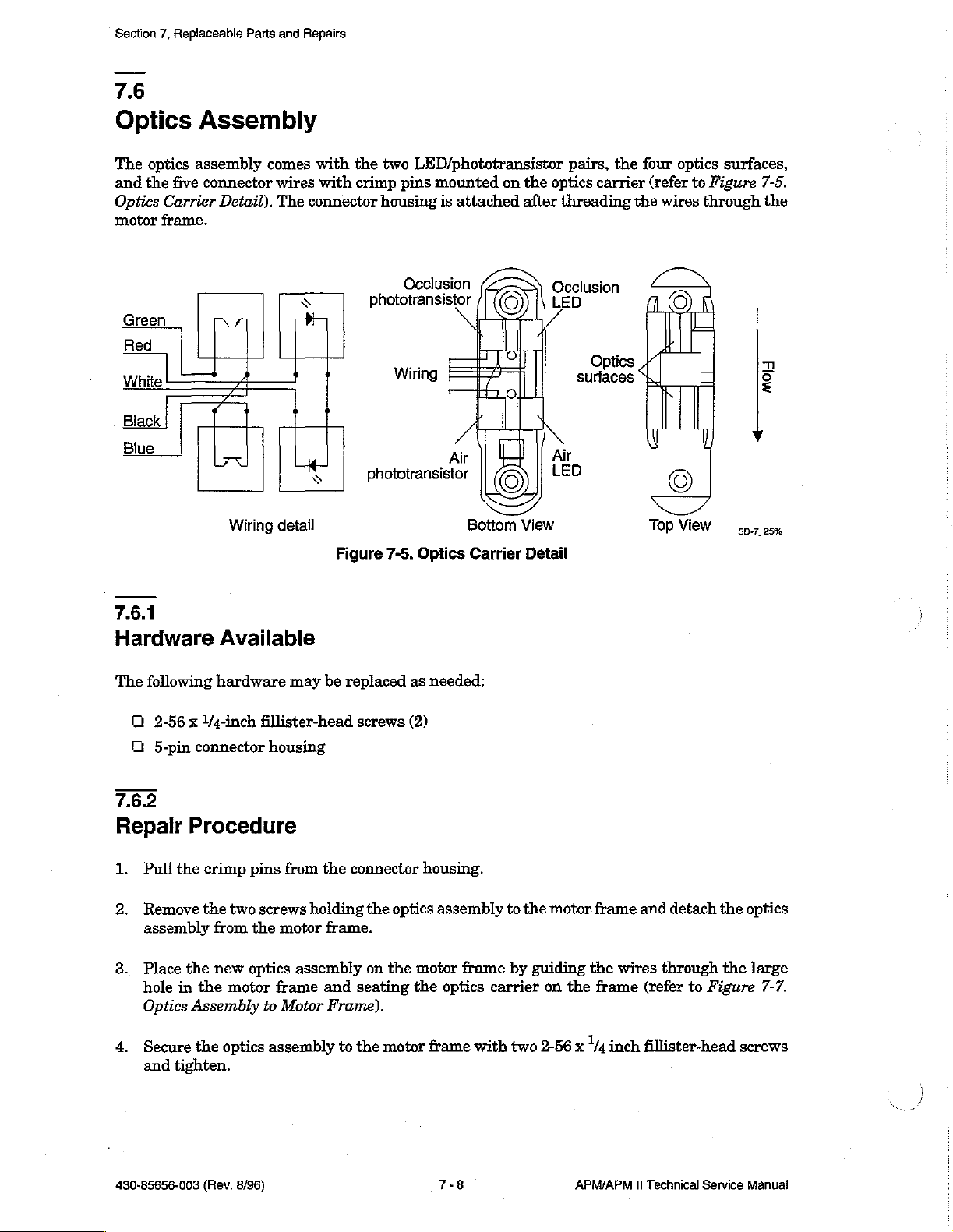
Optics
The
optics
and
the
five
Optics
motor
Green
Blue
frame.
Red
White
Black
Carrier
Assembly
assembly
connector
Detail).
Mí]
Wiring
comes
wires
The
detail
with
with
connector
<
Di
さ
Figure
the
two
LED/phototransistor
crimp
pins
mounted
housing
phototransistor
is
attached
Occlusion
Wiring
Air
phototransistor
Bottom
7-5.
Optics
Carrier
on
the
after
©
o
o
©
View
Detail
pairs,
optics
carrier
threading
Occlusion
Optics
surfaces
Air
LED
the
four
(refer
the
wires
y
T т
©
Top
optics
to
Figure
through
©
|
|
日
View
surfaces,
7-5.
the
n
2
725%
7.6.1
Hardware
The
following
Q
2-56 x l/4-inch
ロ
5-pin
connector
7.6.2
Repair
1.
2.
8.
4.
Procedure
Pull
the
Remove
assembly
Place
the
hole
in
the
Optics
Assembly
Secure
and
the
tighten.
Available
hardware
fillister-head
housing
crimp
pins
the
two
screws
from
the
motor
new
optics
motor
optics
frame
to
Motor
assembly
may
be
from
the
holding
frame.
assembly
and
Frame).
replaced
screws
connector
the
on
the
seating
to
the
motor
as
needed:
(2)
housing.
optics
motor
the
frame
assembly
frame
optics
carrier
with
to
by
two
the
guiding
2-56
motor frame
the
wires
on
the
frame
x 1/4
inch
and
detach
through
(refer
fillister-head
to
Figure
the
the
screws
optics
large
7-7.
430-85656-003
(Rev.
8/96)
7-8
APM/APM
II
Technical
Service
Manual
Page 2
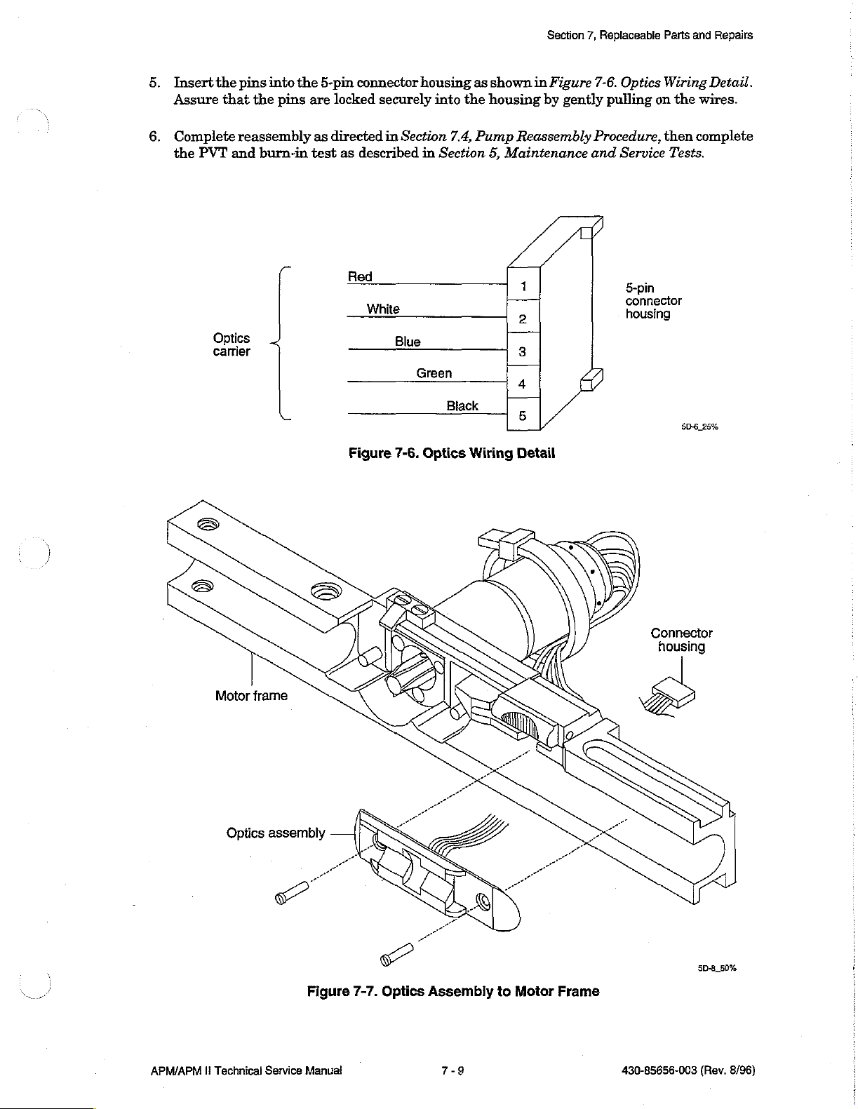
Insert
Assure
the
that
pins
the
into
pins
the
are
5-pin
locked
connector
securely
housing
into the
as
shown
housing
Section
in
Figure
by
7,
Replaceable
7-6.
gently
Optics
pulling
Parts
Wiring
on
the
and
Repairs
Detail.
wires.
Complete
the
PVT
Optics
carrier
reassembly
and
burn-in
as
directed
test
as
—Nhite
in
described
Red
i
-一
Figure
Blue
7-6.
Section
in
Section
Green
Optics
7.4,
Black
Wiring
Pump
Reassembly
5,
Maintenance
|
人
4
Detail
1
2
3
5
Procedure,
and
Service
5-pin
connector
housing
then
Tests.
5D-6_25%
complete
Motor
frame
Optics
assembly
Figure
7-7.
Optics
Assembly
to
Motor
Frame
Connector
housing
5D-8_50%
APM/APM
li
Technical
Service
Manual
7-9
430-85656-003
(Rev.
8/96)
Page 3
Section
77
7,
Replaceable
Parts
and
Repairs
Motor
The
motor
and
housing
Note:
7.7.1
Hardware
The
7.7.2
Repair
1.
Loctite®
following
Q
M2 x 16
С
9-pin
Q
Wires
Remove
from
the
Procedure
Assembly
assembly
fully
Available
hardware
mm
connector
(various
the
frame.
comes
assembled.
Threadlocker
flat-head
housing
colors)
three
flat-head
may
with
the
222
be
ordered
screws
screws
motor,
is
required
(3)
holding
motor
for
this
for
replacement:
the
shaft
extension,
procedure.
motor
to
the
and
motor
motor
frame
connector
and
lift
the
wires
motor
2.
3.
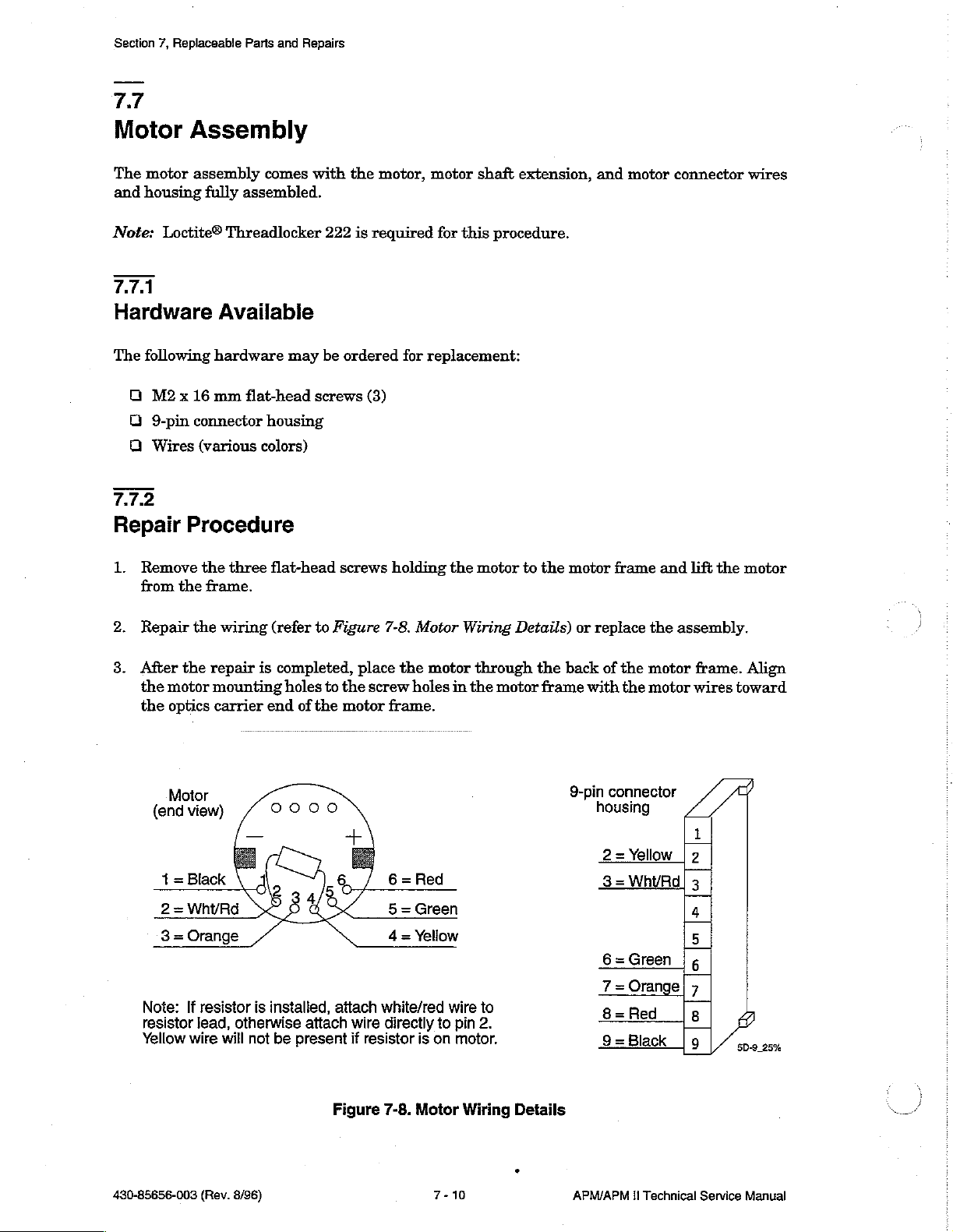
Repair
After
the
the
Note:
resistor
Yellow
the
wiring
the
repair
motor
mounting
optics
carrier
Motor
view)
(end
Black
=
1
WhyRd
=
2
resistor
If
lead,
will
wire
(refer
is
completed,
holes
end
installed,
is
otherwise
be
not
to
Figure
to
of
the
attach
attach
present
place
the
screw
motor
wire
resistor
if
7-8.
Motor
the
motor
holes
frame.
white/red
is
to
on
directly
Wiring
through
in
the
wire
pin
motor.
motor
to
2.
Details)
the
back
frame
9-pin
or
replace
of
with
connector
housing
=
2
3=WhyRd|
6=Green
7=Orange|
=
8
TTT]
9=Black
the
the
Yellow
Red
the
assembly.
motor
motor
|
frame.
wires
1
2
3
4
5
is
7
8
|9
Align
toward
25%
SD
430-85656-003
(Rev.
8/96)
Figure
7-8.
Motor
7-10
Wiring
Details
APM/APM
il
Technical
Service
Manual
Page 4
Section
7,
Replaceable
Parts
and
Repairs
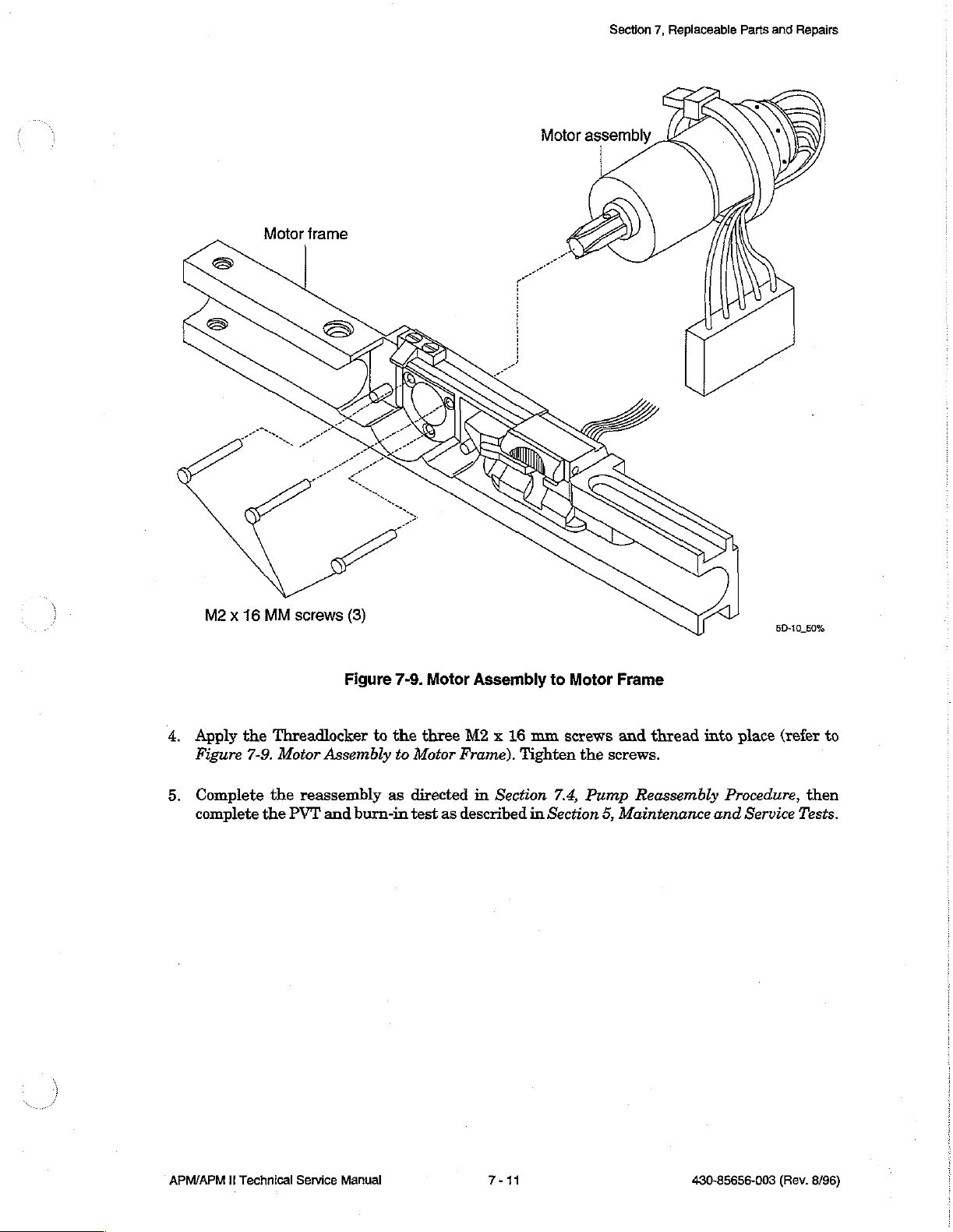
Motor frame
M2 x 16
MM
screws
(3)
5D-10
50%
4.
Apply
Figure
5.
Complete
complete
the
Threadlocker
7-9.
Motor
the
reassembly
the
PVT
Figure
to
Assembly
and
burn-in
7-9.
the
three
to
Motor
as
directed
test
Motor
Frame).
as
described
Assembly
M2 x 16
Tighten
in
Section
to
mm
7.4,
in
Section
Motor
serews
the
Pump
5,
Frame
and
thread
screws.
Reassembly
Maintenance
into
place
Procedure,
and
Service
(refer
then
Tests.
to
APM/APM
1!
Technical
Service
Manual
7-11
430-85656-003
(Rev.
8/96)
Page 5
Section
7.8
7,
Replaceable
Parts
and
Repairs
Latch
The
7.8.1
Assembly
latch
assembly
Hardware
Ejector
7.8.2
Repair
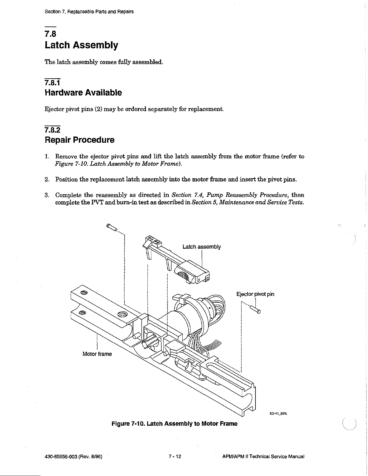
1.
2.
8.
pivot
Procedure
Remove
Figure
Position
Complete
complete
7-10.
comes
Available
pins
(2)
may
the
ejector
Latch
the
replacement
the
the
PVT
pivot
Assembly
reassembly
and burn-in
fully
be
ordered
pins
latch
as
assembied.
separately
and
lift
to
Motor
Frame).
assembly
directed
test
as
described
for
the latch
into the
in
Section
in
replacement.
assembly
motor frame
7.4,
Section
from
Pump
5,
Maintenance
the
motor
and
insert
Reassembly
frame
the
pivot
Procedure,
and
Service
(refer
pins.
then
Tests.
to
430-85656-003
Motor
(Rev.
frame
8/96)
Figure
7-10.
Latch
Assembly
7-12
to
Motor
Frame
APM/APM
Ejector
Il
Technical
pivot
pin
$D-11
50%
Service
Manual
Page 6

7.9
Section
7,
Replaceable
Parts
and
Repairs
PCB
The
schematics
7.9.1
Assembly
PCB
assembly
and
Components
The
following
O
Beeper
O
Bolus
O
12-VDC
Q
Lithium
A
LCD
components
Jack
Power
Battery
Module
7.9.2
Materials
Soldering
RTV
is
used
Required
iron
and
to
comes
drawings
Available
Jack
solder
reattach
the
fully
assembled
of
the
may
are
used
resonator
APM
be
replaced
to
replace
and
and
APM
individually:
bolus
to
the
PCB
tested.
II
printed
jack,
when
Refer
to
circuit
power
replacing
Section
boards.
jack,
lithium
the
9,
Drawings,
battery,
beeper.
for
detailed
and
beeper.
7.9.3
Repair
CAUTION:
methods
Replace
PCB
Pump
5,
7.9.3.1
Beeper
1.
2.
8.
4.
individual
assembly
Reassembly
Maintenance
Remove
Remove
Place
Apply
Procedure
The
PCB assembly
while
working
components
or
any
Procedure,
and
Service
resonator
solder
replacement
RTV
and
to
resonator.
is
with
the
as
individual
then
Tests.
from
around
lift
beeper
beeper
on
PCB
Replace
electrostatic
PCB.
described
component,
complete
beeper.
off
of
and
the
in
the
Clean
the
PCB.
solder
resonator
sensitive.
the
following
complete
PVT
and
off
old
in
place
around
Use
ESD
sections.
reassembly
burn-in
adhesive
(refer
to
Figure
the
beeper
safety
After
as
test
from
and
replacing
directed
as
described
around
7-11.
PCB
then
seat
precautionary
the
entire
in
Section
resonator.
Back
on
the
in
Section
Detail).
board.
7.4,
APM/APM
II
Technical
Service
Manual
7-13
430-85656-003
(Rev.
8/96)
Page 7

Section
7,
Replaceable
Parts
and
Repairs
(6P)
Moe[
Jemod
(LdS)
Jedeeg
(kr)
Jonoeuuoo
Aepeg
토로
5
O
(80)
HERE
αμ
ln
hi
O
Lo
απ.»
Or
L
KA
Lo
OÙ
a
qu
m
co
Nr
al.
圖
ММ
№
за
m
aw
o
o
o
9
o|o
9
fa
E
o
o
o
o
.
ΟΟΟΟΝΙΙΟΟΟΟΟΟΟΟΝΣ
sr
/
7
e
D
(Sp)
Joloeuuoo
soldo
(Ef)
Jojosuuoo
T+
ュー
ン
9
JoJo
ue
(ia)
xoel
snjog
[Fear
=
М
|-
ших
o
圖
IT
-ν
=
GE
a
a
EN
|
ии
=
yul
È
„=
ala
圖
圖
ml
me
o
ο
fc
ниниии
o
ms
a
LI]
8
Figure
η
а
“EE
[E]
인비
=
=
=
=
=
=
|
an
Pon
7-11.
88
a
=
ΗΝ
PCB
Μα
om
TEE
απ.
ea
mun
Back
ши
Calata)
ow
м
sus
a
Detail
ma
ll
画面
Mo
vin
SS
Ce
πι
|
min
3
ği
Tm
1180
"n
슨
자타
EM
gia
圖
13
加
Idi
LIL
on
b
©
SE-3
Aspeg
100%
430-85656-003
(Rev.
8/96)
7-14
APM/APM
II
Technical
Service
Manual
Page 8

7.9.3.2
Bolus
1.
2.
7.9.3.3
12-VDC
1.
2.
Jack
Remove
Place
Detail).
Remove
Place
PCB
7934
Lithium
solder
replacement
Power
the
the
Back
and
Jack
solder
replacement
Detail).
Battery
lift
bolus
bolus
and
lift
12-VDC
jack
jack
the
off
on-PCB
12-VDC
power
of
the
and
power
jack
PCB.
solder
jack
on the
leads
off
PCB
the
and
Section
(refer
PCB.
solder
7,
Replaceable
to
Figure
leads
7-11.
(refer
Parts
to
Figure
and
PCB
Repairs
Back
7-11.
1.
Remove
2.
Place
PCB
7.9.3.5
LCD
1.
Gently
pins.
2.
Assurgtha&the
the
the
replacement
Back
Detail).
solder
and
|
lift
lithium
C
Module — 2720602.
pull
the
LCD
module
connectors
then
snap
the
the
lithium
battery
up
of
the
display
battery
on
the
and
off
of
the
replacement
securely
off
PCB
-
PCB,
LCD
into
of
the
and
uns
being
module
place
PCB.
solder
*
careful
are
(refer
leads
(refer
5342/32
not
to
damage
aligned
to
Figure
with
7-12.
to
Figure
the
LCD
the
guide
guide
Module
7-11.
pins
APM/APM
Guide
(PCB
II
Technical
pins
detail
not
shown)
SE2
(Rev.
259
8/96)
Service
Figure
Manual
7-12.
LCD
Module
7-15
Mounted
on
PCB
430-85656-003
Page 9

Section
7,
Replaceable
7.10
Parts
and
Repairs
Front
The
front
Case
case
7.10.1
Component
Assembly
assembly
Available
comes
fully
Figure
assembled
7-13.
Front
(refer
Case
to
Figure
Assembly
7-13.
,
Front
Case
Assembly).
5B-2
25%
The
LCD
Case).
7.10.2
Repair
After
replacing
directed
as
described
To
replace
1.
Detach
2.
If
necessary,
completely.
8.
Remove
inside
4.
Rub
case.
window
may
Procedure
the
in
Section
in
Section
the
LCD
the
LCD
clean
the
paper
the
front
the
back
of
be
entire
7.4,
Pump
5,
Maintenance
window,
window
the
adhesive
case
facing
the
window
replaced
front
case
Reassembly
proceed
from
the
inner
front
protector
the
to
assure a complete
individually
assembly
Procedure,
and
Service
as
follows:
front
case,
case
surface
from
front.
(refer
or
being
the
to
Figure
the
LCD
window,
then
complete
Tests.
careful
with isopropyl
matte
sealing
not
surface
of
the
7-14.
complete
the
to
damage
alcohol
of
the
window
LCD
PVT
the
LCD
adhesive
Window
reassembly
and
burn-in
case
and
allow
window
to
to
Front
or
keypad.
to
and
the
as
test
dry
place
front
5.
Remove
430-85656-003
the
(Rev.
clear
8/96)
protective
cover
from
the
7-16
smooth
surface
of
the
APM/APM
window.
II
Technical
Service
Manual
Page 10

Section
7,
Replaceable
Bare
front
Parts
case
and
Repairs
Figure.7-14.
LCD
Window
to
Front
Case
5B-1
50%
APM/APM
II
Technical
Service
Manual
7-17
430-85656-003
(Rev.
8/96)
Page 11

Section
7,
Replaceable
Parts
and
Repairs
This
page
intentionally
left
blank.
430-85656-003
(Rev.
8/96)
APM/APM
El
Technical
Service
Manual
Page 12

n
Section
8
Specifications
Physical
Pump
Time
Dimensions:
Weight:
Functional
Mechanism:
Display:
of
Day
Clock:
17.1
(H) x 10
Approximately
One
microcomputer-controlled
Two-line,
On
AC
power:
On
battery
program
backlight
seconds
does
12-hour
clock
after
not
activate
clock
without
(W) x 5.8
1.0
kg
liquid
crystal
continuously
power:
continuously
review, and
is
activated
the
keystroke.
the
with
AM/PM
AM/PM
(D)
cm
(6.75 x 4.0 x 2.3
(2
pounds)
display
backlit
history
by
display.
keystrokes
Pressing
backlight
displayed
displayed
inches)
eccentric-rotor
(LCD)
with
backlit
At
and
the
peristaltic
backlight
during
other
remains
remote
adjustable
motor
programming,
times,
on
for
bolus
to
24-hour
the
three
switch
Operating
Printer
Memory
Protection:
Electrical
Environmental
Temperature
Relative
Atmospheric
Controls:
interface:
Safety:
Ranges:
Humidity:
Pressure:
Accuracy:
Keypad:
ON/OFF:
Remote
Jack
Printers:
Printer
Bolus:
and
Port:
+3
24
One
isolated
Kodak
Nonvolatile
batteries
Meets
are
CSA
standards
Operating:
Shipping
10
to
0
to
and
90
percent
10,000
minutes/month
membrane-type
electromechanical
Jack
for
remote
interface
Diconix
RS232C
memory
removed
(NRTL)
+10
to
Storage:
feet
(0
to
150
serial
of
up
from
guidelines
+40
degrees
-20
3,000
or
better
switches
switch
circuit
Plus
interface
to
256
events
pump
and
Celsius
to
+60
m)
equivalent
switch
connection
or
180si,
port
IEC
601-1-1 and
degrees
or
Seiko
for
up
to
Celsius
pressure
DPU411
one
year
601-1-2
when
APM/APM
II
Technical
Service
Manual
8-1
430-85656-003
(Rev.
8/96)
Page 13

Section
8,
Specifications
Power
Disposable
Sources
AC
Power:
Batteries:
AC
power
international
not
indicate
Use
cord
Power
13036-04
(domestic)
13036-24
(int'
13036-36
(int'l
plug-in)
Two
Capacity:
indicator:
Abbott
and
molded
Supply
table
or
UK
9-V
Duracell
Approximately
if
List
top)
or
wall
plug
the
18036
plug
-54
Amber
icon
on
voltage
AC
115
60
0.18
220-240
50
12
230
50
12
alkaline
four
colored
the
keypad;
is
correct
Power
Hz
Hz
VA
Hz
VA
batteries
Adapter
Input
VAC
А
УАС
VAC
or0.10A
days
LED
next
illuminated
with
at
6.0
mL/hr
to
the
LED
3.6 m (12
Output
12
VDC
0.4
À
12
VDC
0.3A
12
VDC
0.4
or
0.5
does
ft)
A
Rechargeable
Occlusion
Occlusion Alarm
Maximum
{Audible
and
Pack:
Pressure
Pressure:
Delivery
Pressure:
Alarms
Visual)
Attachable
Recharge
Capacity:
45
psi
45
psi
Low
Limit
End
Check
Amount
System
time:
(310
(310
batteries
exceeded
ofinfusion
cartridge
too
error
separate
Approximately
kPa)
Full
battery
recharge
kPa)
On
Callback
Empty
Air-in-line
small
Amount
Internal
pack
requires
five
days
batteries
alert
container
too
large
malfunction
at
up
6.0
to
six
mL/hr
Change
Purge
Check
Occlusion
hours
batteries
overuse
printer
430-85656-003
(Rev.
8/96)
APM/APM
II
Technical
Service
Manual
Page 14

Section
8,
Specifications
Programmable
Ranges
Concentration
Delivery
Bolus
Doses
Flow
Bolus
Delivery
Entry
Rate
and
Loading
rate:
125
Lockout
Limit
mL/hr
Time
0.1 - 50.0
0.1 - 1000
0.1 - 25
0.1 - 9999.9
0.1 - 9999.9
mg
and
equivalent
0.1 - 25
0.1 - 9999.9
0.1 - 9999.9
mg
and
equivalent
5 - 99
min.
5 - 999
4
hour
APM APM
mg/mL
pg/mL
mL/hr
ug
entries
mL
yg
entries
(dom)
min.
limit
mg/hr
ug/hr
mg
Lg
(int!)
0.1 - 50.0
0.1 - 25
0.1 - 9999.9
cannot
0.1
0.1 - 9999.9
cannot
5 - 999
1 -
1000
1 -
999999
exceed
-25
1 -
999999
exceed
1
or 4 hour
min.
Il
mg/mL
pg/mL.
mL/hr
mg/hr
ug/hr
25
mL/hr
mL
mg
ug
25
mL
limit
Container
(Volume)
Air
Sensitivity
Size
0.4 - 1000
mL
0.1 - 9999.9 mg
0.1 - 9999.9
Cont/Cont+Bolus:
continuous
Bolus
0.1 - 1000
0.1 - 9999.9
0.1 - 9999.9
mg
and
equivalent
High
(pump
Low
(pump
Off
(air
Only:
mL
pg
alarm
ug
delivery
must
mg
ug
entries
alarms
alarms
off)
0.1 - 1000
0.1 - 9999.9
1 - 999999
must
be
greater
over
limit
be
at
least
0.1 - 1000
0.1 - 9999.9
1 -
999999
cannot
at
at
approx.
approx.
exceed
period
one
bolus
1000
100
ul)
300
pL)
mL
than
mg
pg
dose
mL
mg
ug
mL
APM/APM U Technical
Service
Manual
8-3
430-85656-003
(Rev.
8/96)
Page 15

Section
8,
Specifications
This
page
intentionally
left
blank.
430-85656-003
(Rev.
8/96)
APM/APM
II
Technical
Service
Manual
 Loading...