

Page 1

ABBOTT
6
aim”
ABBOTT
aim
Technical
Service
Manual
For
use
with
the
following
13038-04,
13967-04,
Abbott
Abbott
AIM
AIM
list
Plus
plus
numbers:
ABBOTT
NORTH
USA
LABORATORIES
CHICAGO,
IL
60064
430-600035-002
(Rev.
11/99)
Page 2

©
Copyright
This
document
Laboratories
sale.
Any
whole
or
1999
party
in
part
and
retains
using
nor
the
subject
all
the
exclusive
this
document
disclose
it
to
matter
rights
accepis
others
Abbott
Laboratories
disclosed
of
dissemination,
it
in
without
herein
confidence,
the
written
are
proprietary
reproduction,
and
agrees
consent
of
Abbott
AllRights
information.
manufacture,
not
Reserved
to
duplicate
Laboratories.
Abbott
and
it
in
Page 3
List
of
Changes
Part
Number
Description
of
Change
Remove
Destroy
and
Pages
Insert
Change
Pages
430-600035-001
(Rev.
12/96)
430-600035-002
(Rev.
10/99)
Original
Second
Section
checklist
Added
performing
encoder
torque
alternate
Section
February
Section
RTV
General:
printer.
issue.
issue.
5:
(1)
Updated
to
match
alternate
the
motor
test,
and current
brake.
Revised
results.
6:
Added
29 on leap
7:
Added
sealing.
Added
pump
inspection
current service
PVT
procedures
test,
servo
supply
PVT
Data
procedure
years.
alternate
Seiko
for
instructions
DPU414
training.
for
calibration,
test
Form
setting
(2)
without
to
a
add
for
as
compatible
N/A
All
N/A
All
AIM/AIM
Plus
Technical
Service
Manual
i
430-600035-002
(Rev.
11/99)
Page 4

Changes
This
page
intentionally
left
blank.
430-600035-002
(Rev.
11/99)
AIM/AIM
Plus
Technical
Service
Manual
Page 5
Table
of
Contents
Section
1
Introduction
1.1
1.2
1.3
Scope
AIM
1.2.1
1.2.2.
Conventions
Section 2 Warranty
Section 3 System
Section 4 Theory
4.1
General
4.2
Circuit
4.3
Detailed
4.3.1
4.3.2
.
and
AIM
Plus
Pump
Description
AIM
and
.
Operating
of
Operation.
Description
Block
Diagram
Circuit
CPU
System
4.3.1.1
4.3.1.2
4.3.1.3
4.3.1.4
4.3.1.5
4.3.1.6
4.3.1.7
4.3.1.8
4.3.1.9
4.3.1.10
4.3,1.11
4.3.21
4.3.2.2
4.3.2.3
4.3.2.4
Microprocessor
EPROM
Microprocessor
RAM
Time
Display
Encoder
Backup
Keypad
Bolus
Serial
Analog
Power
Audible
Air
Overview
AIM
Plus
Manual
.
Description
. . . . .
Of
Day
Interface
Microprocessor
Interface
Switch
Interface
Circuits
Circuits
Alarm
and
Occiusion
Motor
Drive
.
.
Differences
.
(CPU)
.
Supervisory
Clock
Circuit.
.
Interface
.
Optics
Circuit
.
.
.
.
.
.
Interface
.
o.
Circuit
. -
4-10
4-10
4-10
4-11
4-11
4-11
4-12
4-13
4-13
Section 5 Maintenance
5.1
Cleaning
5.2
Inspecting
5.2.1
AIM/AIM
Plus
Technical
Service
Manual
and
the
the
Pump
Service
Pump
.
Pump
and
Inspection
Tests
Accessories
.
. .
o.
.
430-600035-002
(Rev.
5-1
5-2
5-4
5-4
11/99)
Page 6
Page 7
Contents
Section 6 Troubleshooting
6.1
Technical
6.2
Setting
6.3
Troubleshooting
6.3.1
6.3.2
6.3.3
6.3.4
6.3.5
6.3.6
64
Software
Section 7 Replaceable
7.1.
Spare
7.2
Safety
7.3.
Pump
74
Pump
7.4.1.
75
Back
7.5.1
7.6
Optics
7.7
Motor
7.8
Latch
7.8.1
7.9
PCB
7.9.1
7.10
Front
7.10.1
7.10.2
740.3
7.10.4
7.10.5
7.10.6
7.11
Display
7.11.1
7.11.2
Assistance
February
Alert
Alarm
6.3.2.1
6.3.2.2
Servo
Troubleshooting
Port
Assignments
IC
Location
Diagnostic
Parts
Parts
Price
Precautions
Disassembly
Reassembly
Alternate
Case
Assembly
AIM
Beeper
Assembly
Assembly.
Assembly.
Latch
Assembly
ALM
Plus
Case
Assembly
Keypads
Display
Front
Bolus
AC
Power
Battery
Module
FFC
Spacer
.
29
on
Tables.
Messages.
Codes
Function
Hardware
Calibration
Codes
Tests
and
List
.
Procedure
Procedure.
Assembly
.
Spring
Case
Jack.
.
Jumper
.
.
Beeper.
.
Window
Labels
Jack
Connector
.
Cushion
. .
Leap
Years
Alarms
and
Software
Failure
001-007
Codes
Problems
Repairs
.
.
instructions
.
Cable
.
.
and
-
and
Alarms
.
008-143
Solutions
-
for
RTV
,
Jumper
.
.
o.
Sealing
6-1
6-1
6-1
6-2
6-2
64
6-5
6-6
6-14
6-15
6-21
6-24
6-26
7-1
7-1
7-1
7-2
7-5
7-8
7-14
7-12
7-13
7-14
7-15
7-16
7-18
7-18
7-19
7-19
7-20
7-20
7-21
7-21
7-22
7-23
7-24
7-24
AIM/AIM
Plus
Technical
Service
Manual
v
430-600035-002
(Rev.
11/99)
Page 8

Contents
Section 8 Specifications
Section9
Drawings
.
.
.
430-600035-002
(Rev.
11/99)
vi
AIM/AIM
Plus
Technical
Service
Manual
Page 9
List
of
Figures
Figure
Figure
Figure
Figure
Figure
Figure
Figure
Figure
Figure
Figure
Figure
Figure
Figure
Figure
Figure
Figure
Figure
Figure
Figure
Figure
Figure
Figure
Figure
Figure
Figure
Figure
Figure
Figure
Figure
Figure
Figure
Figure
Figure
Figure
Figure
Figure
Figure
Figure
4-1.
Assemblies
4-2.
Motor
4-3.
Motor
4-4.
Optics
4-5.
Latch
4-6.
Circuit
5-1.
Cartridge
5-2.
Basic
5-3.
Optics
7-1.
Back
7-2.
Front
7-3.
Motor,
7-4.
AIM
7-5.
Pump
7-6:
RTV
7-7.
RTV
7-8.
RTV
7-9.
Motor
7-10.
Back
7-11.
AIM
7-12.
Optics
7-13.
Motor
7-14.
Latch
7-15.
PCB
7-16.
Front
7-17.
Bolus
7-18.
Battery
7-19.
Display
9-1.
AIM
9-2.
AIM
9-3.
AIM
9-4.
AIM
9-5.
AIM
9-6.
AIM
9-7.
AIM
9-8.
AIM
9-9.
AIM
9-10.
AIM
.
Frame
Assembly
Assembly
Assembly
Block
Channel
Equipment
Test
Case
Case
Optics,
and
AlM
Assembly
Sealing
Sealing
Sealing
Frame
Case
Beeper
Carrier
Assembly
Assembly
Front
Case
and
Connections
Module
Analog
Microprocessor
Power
PC
Board,
PC
Board,
Plus
Analog
Plus
Microprocessor
Plus
Power
Plus
PC
Plus
Detail
Diagram
Detail
Setup
Block
Placement
Screws
Connections.
and
Plus
PCBs
for
Printer
for
Side,
for
Motor
Seal.
Labels
Installation
to
Motor
to
to
View
Keypads
AC
Power
Installation
Schematic
and
Miscellaneous
Front
Back
Schematic
and
Board,
PC
Board,
.
.
Beeper
Connections
to
Back
Port
Bottom
Frame
.
,
Frame
Motor
Frame
Motor
Frame
and
Labels
Jack
Installation.
.
(CPU)
Schematic.
Side
Side
.
(CPU)
Miscellaneous
Front
Side
Back
Side
.
o.
Cases
Case
.
.
.
.
Circuitry
Schematic
Circuitry
.
.
.
. . . .
Schematic.
.
.
. . .
Schematic
. .
..
. . .
.
.
4-1
4-2
4-3
4-3
4-4
46
5-3
5-8
5-14
7-2
7-3
7-4
7-5
7-6
7-8
7-8
7-9
.
7-9
7-11
7-12
7-13
7-14
7-15
7-17
7-20
7-21
7-22
7-23
Fold-out
Fold-out
Fold-out
Fold-out
Fold-out
Fold-out
Fold-out
Fold-out
Fold-out
Fold-out
AIM/AIM
Plus
Technical
Service
Manual
vii
430-600035-002
(Rev.
11/99)
Page 10

Figures
This
page
intentionally
left
blank.
430-600035-002
(Rev.
11/99)
viii
AIM/AIM
Plus
Technical
Service
Manual
Page 11
List
of
Tables
Table
Table
Table
Table
Table
Table
Table
Table
Table
Table
1-1.
AIM
and
1-2.
AIM
and
5-1.
Cleaning
6-1.
AIM/AIM
6-2.
AIM/AIM
6-3.
AIM/AIM
6-4.
Servo
Calibration
6-5.
Troubleshooting
6-6.
AIM/AIM
6-7.
AIM/AIM
AIM
Plus
AIM
Plus
Solutions.
Plus
Alert
Plus
Alarm
Plus
Alarm
Failure
.
Plus
Port
Plus
IC
Location
Hardware
Software
Differences
Messages
Codes
Codes
001 - 007.
008 - 143.
Codes
o
Assignments
Codes
Differences
..
.
.
.
.
.
.
1-3
1-3
5-2
6-3:
6-5
6-14
6-15
6-21
6-24
AIM/AIM
Plus
Technical
Service
Manual
ix
430-600035-002
(Rev.
11/99)
Page 12

Tables
This
page
intentionally
ieft
blank.
430-600035-002
(Rev.
11/99)
AIM/AIM
Plus
Technical
Service
Manual
Page 13
Po
ㄴㄴ
Section
1
Introduction
11
Scope
This
Technical
Infusion
pumps.
analog
It
is
Manager
It
is
and
organized
ロ
Section 1 Introduction
Section2
ロロ
Section 3 System
Section 4 Theory
Service
(AIM™)
intended
digital
microprocessor-based
into
Warranty
Manual
for
the
the
following
Operating
of
and
trained
Operation
presents
Abbott
technician
nine
sections:
Manual
technical
Ambulatory
experienced
equipment.
information
Infusion
Manager
in
analysis,
about
the
Abbott
Plus
(AIM®
troubleshooting
Ambulatory
Plus)
infusion
and
repair
of
ロロ
Section 5 Maintenance
Section 6 Troubleshooting
ロロ
Section 7 Replaceable
Section 8 Specifications
ロロ
Section9
Note:
In
AIM
Plus
Note:
figures
depending
Ifa
contact
Figures
may
problem
Abbott
this
unless
Drawings
manual,
otherwise
are
rendered
not
exactly
on
the
configuration
in
the
infusion
Laboratories
the
reflect
and
Parts
terms
“pump”
specified.
as
graphic
the
product.
of
system
operation
Technical
Service
and
Tests
Repairs
and
“pumps”
representations
Display
the
pump
in
use.
cannot
Support
Operations
refer
to
to
approximate
screens
be
and
resolved
(see
all
configurations
the
actual
touchswitch
using
Section
labels
the
information
6.1,
Technical
of
both
product;
may
vary
in
Assistance).
the
AIM
therefore,
slightly,
this
manual,
and
AIM/AIM
Plus
Technical
Service
Manual
1-1
430-600035-002
(Rev.
11/99)
Page 14
Section
12
1,
Introduction
AIM
The
noted
and
pumps
in
Section
AIM
share
1.2.1
Pump
The
intravenously
over-pressure
parameter
endangering
The
battery
through a 24-key
16-character
dedicated
and
Description
Abbott
pump
of
AIM
monitoring,
the
is
powered
packs,
by
cartridges
the
cartridge
or
(occlusion)
or
Plus
the
same
design
1.2.2,
AIM
and
AIM
epidurally.
alarm,
and
patient.
by
four
an
AC
power
keypad
4-line
alphanumeric
to
deliver
assure
Overview
and
and
AIM
Plus
are
Special
an
numerous
1.5V
AA
supply.
on
the
front of
fluids
accurate
functionality
Plus
Differences.
single-channel
other
safety features
air-in-line
failure
alkaline
The
liquid
through
fluid
alarm, a back-up
backup
batteries,
pump
the
unit.
crystal
rotary
delivery.
than
the
hardware
infusion
modes
optional
is
microprocessor-based
The
display
peristaltic
pumps
integrated
to
state
into
(safety)
prevent
nickel
of the
(LCD)
pumping
designed
metal
pump
module.
action.
and
software
to
deliver
the
design
microprocessor,
single
point
failures
hydride
and
is
rechargeable
is
programmed
displayed
The
unit
Control
differences
fluids
include
an
motor
from
using
a
requires
of the
pump
The
pump
detects
specification
the
cartridge
proceed
deactivated,
The
pump
Variable
The
pump
place
with
The
pump
pump
is
cables
For
specific
AIM
Plus
occlusion
exceeds.
until
the
refer
has
Time
contains a time-of-day
the
contains a printer
connected
(depending
instructions
System
occlusions
the
air
is
to
the
several
Delivery
pump
can
to
one
on
printer
Operating
and
air
alarm
pressure,
pre-set
cleared
pump’s
and
(the
System
programming
Continuous
be
reviewed
connector
of
the
two
choice)
regarding
Manual.
in
the fluid
the
sensitivity
air
sensitivity
cartridge.
instrument
limit,
Operating
modes:
Delivery.
clock
and
history
on
the
LCD
that
also
recommended
are
available
pump
operation,
sounds
the
pump
setting
Manual
TPN,
Pain
storing
display,
allows
printout
compatible
from
Abbott
refer
to
Ifthe
pressure
an
alarm
will
alarm,
is
variable,
for
more
Management,
capability.
along
with time
of
this
printers.
as
accessory
the
AIM
System
at
the
cartridge
and
stops
delivery.
stop
delivering
and
for
the
AIM
information).
Intermittent
Significant
and
history
Two
different
events
date
of
information
special
items.
Operating
exceeds
Plus
the
If
air
and
not
can
be
Delivery,
that
take
occurrence.
when
the
printer
Manual
or
the
in
430-600035-002
(Rev.
11/99)
1-2
AIM/AIM
Plus
Technical
Service
Manual
Page 15
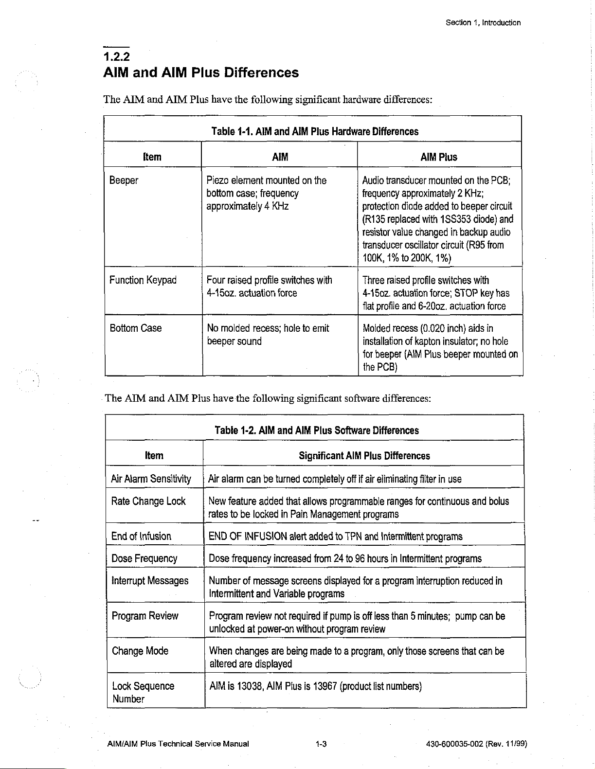
1.2.2
AIM
The
and
AIM
Beeper
Function
Bottom
AIM
and
Item
Keypad
Case
AIM
Plus
Plus
Differences
have
the
following
Table
1-1.
Piezo
element
bottom
approximately 4 KHz
Four
4-450z.
No
beeper
case;
raised
actuation
molded
sound
AIM
and
AIM
mounted
frequency
profile
switches
force
recess;
hole
significant
AIM
Plus
on
to
emit
hardware
Hardware
the
with
differences:
Differences
Audio
transducer
frequency
protection
(R135
resistor
transducer
100K,
Three
4-150z.
flat
Molded
installation
for
the
approximately 2 KHz;
diode
replaced
value
oscillator
1%
to
raised
actuation
profile
and
recess
of
beeper
(AIM
PCB)
AIM
Plus
mounted
added
with
15S353
changed
circuit
200K,
1%)
profile
switches
force;
6-200z.
(0.020
kapton
insulator;
Plus
beeper
Section
1,
Introduction
on
the
to
beeper
diode)
in
backup
(R95
from
with
STOP
key
actuation
inch)
force
aids
in
no
mounted
PCB;
circuit
and
audio
has
hole
on
The
AIM
and
AIM
Plus
have
the
Table
Air
Rate
End
Dose
interrupt
Program
Change
Lock
Number
Item
Alarm
Sensitivity | Air
Change
of
Frequency
Sequence
Lock
Infusion
Messages
Review
Mode
New
tates
END
Dose
Number
Intermittent
Program
unlocked
When
altered
AIM
1-2.
alarm
feature
to
be
OF
INFUSION
frequency
of
changes
are
is
13038,
following
AIM
and
can
be
turned
added
locked
increased
message
and
Variable
review
not
at
power-on
are
displayed
AIM
significant
AIM
Plus
Significant
completely
that
allows
in
Pain
Management
alert
added
from
screens
programs
required
without
being
made
Plus
is
13967
software
Software
AIM
Plus
off
if
air
programmable
programs
fo
TPN
and
24
to
96
hours
displayed
if
pump
program
for a program
is
off
review
to a program,
(product
differences:
Differences
Differences
eliminating
ranges
Intermittent
less
only
list
numbers)
filter
for
continuous
programs
in
Intermittent
interruption
than 5 minutes;
those
screens
in
use
programs
reduced
pump
that
and
can
can
bolus
in
be
be
AIM/AIM
Plus
Technical
Service
Manual
1-3
430-600035-002
(Rev.
11/99)
Page 16
Section
1,
Introduction
13
Conventions
The
following
С
Touchswitches
[ENTER]
Q
Screen
beeps
conventions
displays
sound
are
to
select a 100
referenced
and
the
are
used
described
mL
in
INITIALIZE
throughout
in
all
caps
and
container
the
text
size.”
are
NVRAM
this
manua!:
enclosed
in
all
OR
in
caps,
USE
brackets,
e.g.,
“When
ARROWS
e.g.,
“Press
resetting
display
[1], [0],
is
[0]
complete
returns.”
and
two
Throughout
as
follows:
this
WARNING:
A
warning
Failure
CAUTION:
damage
Note: A note
to
observe a warning
or
manual,
contains
A
caution
failure.
highlights
warnings,
special
cautions,
safety
is
contains
information
information
and
notes
emphasis
potentially
that
helps
explain a concept
are
used
and
life
threatening.
that
could
to
emphasize
-
must
be
prevent
or a procedure.
important
observed
irreversible
at
information
all
times.
equipment
430-600035-002
(Rev.
11/99)
1-4
AIM/AIM
Plus
Technical
Service
Manual
Page 17
|
ЗесНоп
2
Warranty
Subject
warrants
in
Abbott
purpose,
Purchaser’s
no
contract,
event
business,
The
used
or
to
the
that
the
material
and
makes
or
any
exclusive
event
shall
Abbott’s
negligence,
shall
Abbott
revenue,
foregoing
other
than
reliability,
or
terms
product
workmanship
no
other
other
matter.
remedy
strict
be
or
profits.
warranty
in
accordance
in
the
and
conditions
shall
conform
under
warranties,
shall
liability
liable
shall
event
arising
liability,
for
incidental,
Warranty
be
void
with
the
serial
herein,
to
Abbott’s
normal
express
be,
at
Abbott’s
out
tort,
or
product
in
the
product
or
lot
Abbott
Laboratories,
standard
use
and
service
or
implied,
as
option,
of
any
cause
whatsoever
otherwise)
consequential,
returned
event
manuals
number
the
product
so
exceed
as,
has
herein
specifications
for a period
to
merchantability,
the
repair
the
or
special
to
Abbott
has
been
in
Abbott’s
been
altered,
of
two
or
replacement
(whether
price
of
damages
must
be
misused,
judgment,
defaced,
referred
and
be
free
years
fitness
of the
such
cause
such
product,
or
losses
properly
damaged,
to
affect
or
to
as
Abbott,
from
defects
after
purchase.
for a particular
product.
be
and
or
packaged.
altered,
its
removed.
In
based
in
in
no
for
lost
or
stability
The
foregoing
or
attempts
by
an
For
purposes
other
In
providing
liability
whether
acknowledged
an
authorized
to
authorized
than
the
for
the
such
warranty
perform
representative
of
the
replacement
any
actions
person
that
agent
shall
any
preceding
parts
for
or
has
any
person
of
Abbott.
also
be
major
repair
of
Abbott
sentence,
of
accessory
repair
or
inactions
been
trained
other
than
void
in
or
other
and
“major
items
service
of
the
person
to
an
Abbott
the
event
service
using
Abbott
repair
such
of
the
product,
performing
perform
representative
any
person,
on
the
documentation
or
other
as
batteries.
such
repair
including
product
service”
Abbott
such
or
performing
the
without
and
means
shall
have
repair
or
service.
Purchaser,
having
approved
any
no
service,
It
repair
been
spare
repair
responsibility
regardless
is
understood
or
service
performs
trained
parts.
or
service
or
of
and
is
not
AIM/AIM
Plus
Technical
Service
Manual
2-1
430-600035-002
(Rev.
11/99)
Page 18
Section
3
System
A
System
binder’s
contact
Operating
pockets
Abbott
for
Laboratories
Operating
Manual
convenient
is
included
reference.
Technical
with
Ifa
Support
Manual
every
AIM
copy
of
the
Operations
and
AIM
System
(see
Section
Plus
kit.
Operating
Manual
6.1,
Technical
Insert a copy
is
not
available,
Assistance).
in
this
AIM/AIM
Plus
Technical
Service
Manual
3-1
430-600035-002
(Rev.
11/99)
Page 19
0
lå
Section
4
Theory
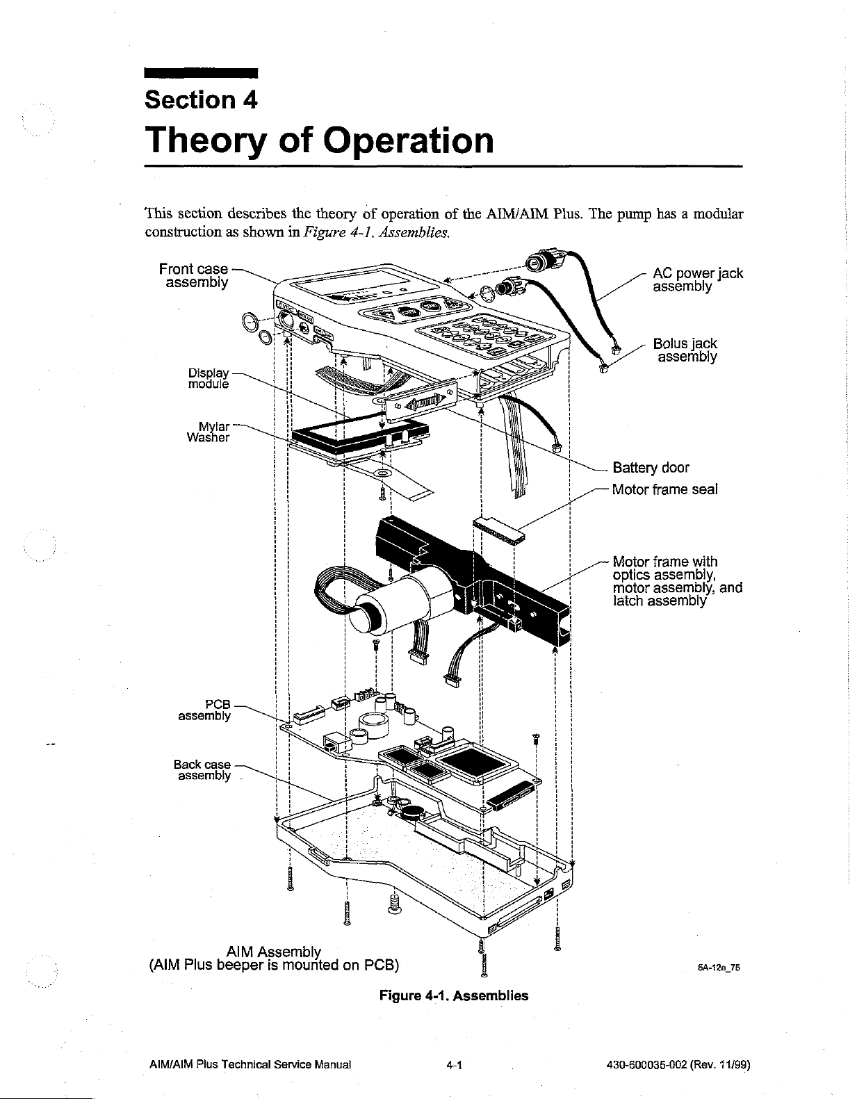
This section
construction
Front
assembly
case
Displa
module
Mylar
Washer
describes
as
shown
of
the
theory
in
Figure
Operation
of
operation
4-1,
Assemblies.
of
the
AIM/AIM
Plus.
The
pump
Battery door
Motor
has a modular
jack
power
AC
assembly
Bolus
jack
assembly
frame
seal
PCB
assembly
Back
case
assembly
.
Motor
optics
motor
latch
frame
with
assembly,
assembly,
assembly
and
(AIM
AIM/AIM
Plus
Plus
AIM
Assembly
beeper
Technical
is
mounted
Service
Manual
on
PCB)
Figure
4-1.
Assemblies
41
430-600035-002
5A-12a
(Rev.
75
11/99)
Page 20
Section
41
4,
Theory
of
Operation
General
The
pump
case
conductive
front
motor
accomplished
access
constructed
connected
The
motor
part
detection
material
half
of
frame
is
accomplished
of
and
frame
of
the
pumping
systems
Description
is
constructed
to
provide
the
case
is
side
by
the
removal
spring
isolated
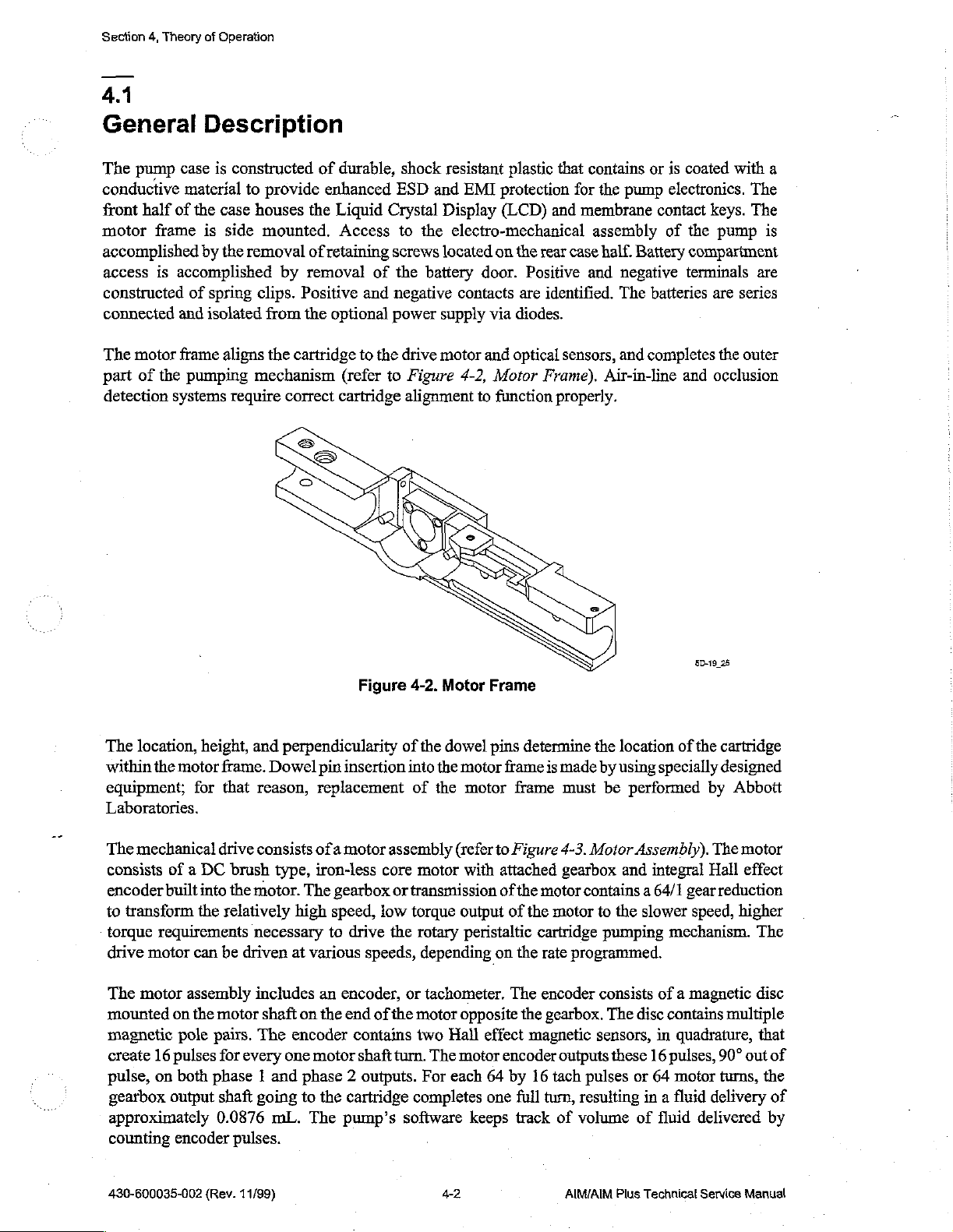
aligns
require
houses
mounted.
clips.
mechanism
by
Positive
from
the
cartridge
correct
the
of
removal
the
of
durable,
enhanced
Liquid
Access
retaining
of
and
optional
to
(refer
cartridge
shock
ESD
Crystal
to
screws
the
negative
power
the
drive
to
Figure
alignment
resistant
and
Display
the
electro-mechanical
located
battery
contacts
supply
motor
4-2,
EMI
door.
via
and
to
on
Motor
function
plastic
protection
(LCD)
the
Positive
are
diodes.
optical
that
contains
for
the
and
membrane
assembly
rear
case
half.
and
identified.
sensors,
Frame).
properly.
Air-in-line
or
is
pump
electronics.
contact
of
Battery
negative
The
batteries
and
completes
coated
terminals
and
with
The
keys.
The
the
pump
compartment
are
are
series
the
outer
occlusion
a
is
The
location,
within
the
equipment;
height,
motor
for
Laboratories.
The
mechanical
consists
encoder
to
torque
drive
The
mounted
magnetic
create
pulse,
gearbox
approximately
counting
of a DC
built
transform
requirements
motor
motor
assembly
on
pole
16
pulses
on
both
output
encoder
into
the
can
the
pairs.
phase 1 and
and
frame.
Dowel
that
reason,
drive
consists
brush
type,
the
motor.
relatively
necessary
be
driven
includes
motor
shaft
The
for
every
shaft
going
0.0876
mL.
pulses.
Figure
perpendicularity
pin
insertion
replacement
ofa
motor
assembly
iron-less
The
high
speed,
to
at
various
an
on
the
encoder
one
motor
gearbox
core
or
low
drive
the
speeds,
encoder,
end
of
the
contains
shaft
turn.
phase 2 outputs.
to
the
cartridge
The
pump’s
4-2.
of
the
into
of
motor
Motor
the
the
dowel
motor
motor
(refer
with
Frame
pins
transmission
torque
or
software
output
rotary
peristaltic
depending
tachometer.
motor
opposite
two
Hall
The
motor
For
each
completes
keeps
effect
64
one
determine
frame
is
frame
to
Figure
attached
of
the
motor
of
the
cartridge
on
the
rate
The
encoder
the
gearbox.
magnetic
encoder
by
16
full
turn,
track
the
location
made
by
using
must
be
4-3.
Motor
gearbox
and
contains a 64/1
motor
to
the
pumping
programmed.
consists
The
sensors,
outputs
tach
of
these
pulses
resulting
volume
50-19
of
the
specially
performed
Assembly).
integral
gear
slower
speed,
mechanism.
of a magnetic
disc
contains
in
quadrature,
16
pulses,
or
64
motor
in a fluid
of
fluid
delivered
25
cartridge
designed
by
Abbott
The
motor
Hall
effect
reduction
higher
The
disc
multiple
that
90°
out
of
turns,
the
delivery
of
by
430-600035-002
(Rev.
11/99)
4-2
AIM/AIM
Plus
Technical
Service
Manual
Page 21
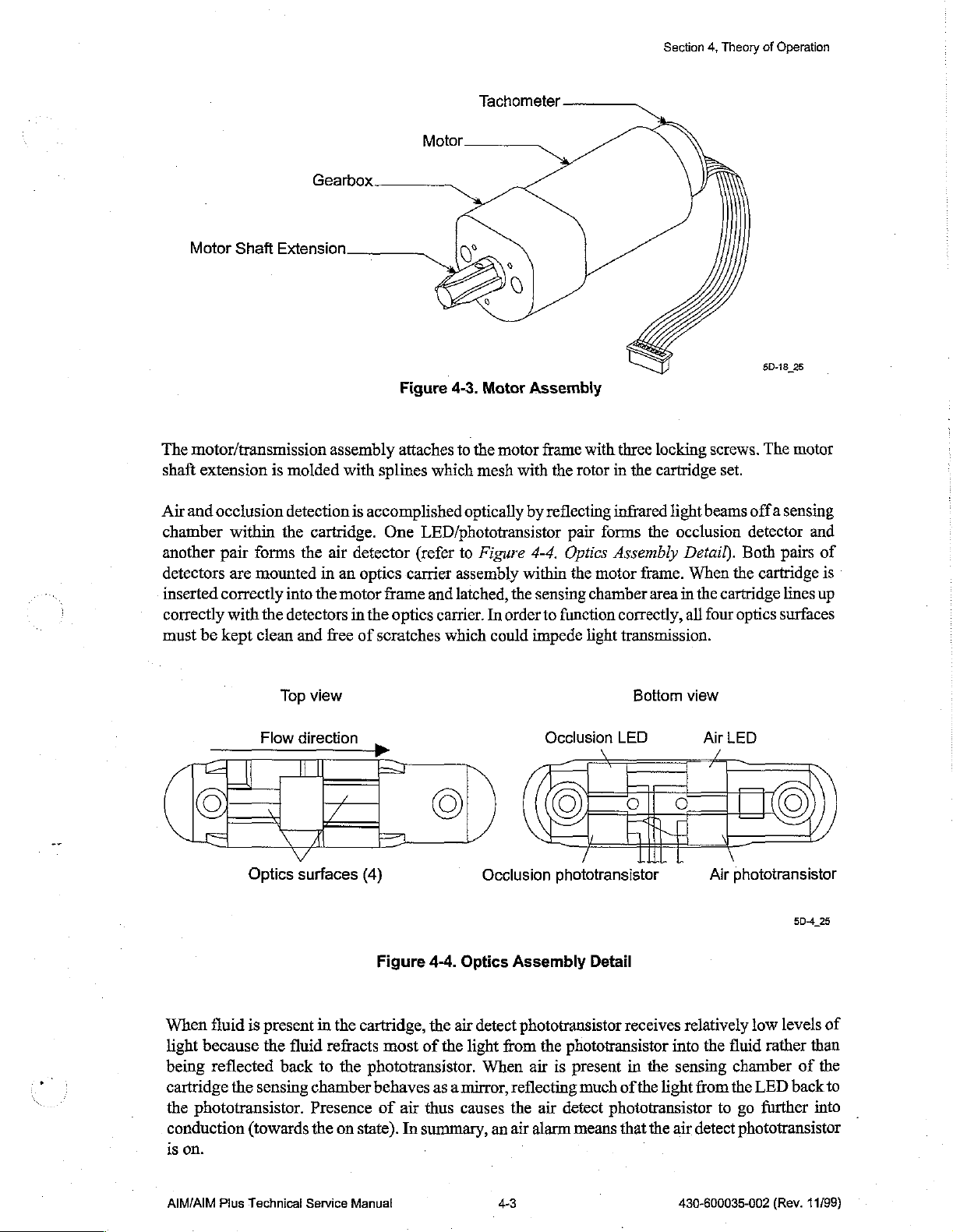
The
motor/transmission
shaft
extension
is
Gearbox
molded
assembly
with
splines
Figure
attaches
4-3.
to
which
Tachometer
Motor
Assembly
the
motor
mesh
with
frame
the
rotor
with
in
three
locking
the
cartridge
Section
4,
Theory
screws.
set.
of
Operation
5D-18
25
The
motor
Air
and
occlusion
chamber
another
detectors
inserted
correctly
must
within
pair
are
correctly
with
be
kept
detection
the
forms
the
mounted
into
the
detectors
clean
and
Top
Flow
direction
is
cartridge.
air
detector
in
an
the
motor
in
free
of
view
Optics
surfaces
accomplished
One
LED/phototransistor
(refer
optics
carrier
frame
and
the
optics
scratches
carrier.
which
©
(4)
Figure
4-4.
optically
to
Figure
assembly
latched,
In
order
the
could
Occlusion
Optics
Assembly
by
reflecting
pair
4-4.
Optics
within
the
sensing
to
function
impede
Occlusion
motor
chamber
light
gele
phototransistor
Detail
infrared
forms
Assembly
correctly,
light
the
occlusion
frame.
area
in
Detail).
When
all
transmission.
Bottom
LED
view
beams
offa
detector
Both
the
cartridge
the
cartridge
four
optics
Air
LED
Air
phototransistor
sensing
and
pairs
of
is
lines
up
surfaces
©
5D4
25
When
fluid
is
present
light
because
being
reflected
cartridge
the
phototransistor.
conduction
on.
is
AIM/AIM
the
Plus
Technical
the
sensing
(towards
fluid
back
chamber
Presence
the
Service
in
the
cartridge,
refracts
to
the
phototransistor.
on
state). In
Manual
most
of
behaves
of
air
thus
summary,
.
the
air
detect
the
light
from
When
as a mirror,
causes
an
4-3
phototransistor
the
phototransistor
air
is
present
reflecting
the
air
detect
air
alarm
means
receives
in
much
ofthe
phototransistor
that
relatively
into
the
sensing
light
from
the
air
detect
430-600035-002
low
the
fluid
rather
chamber
the
LED
to
go
further
phototransistor
(Rev.
levels
of
than
of
the
back
to
into
11/99)
Page 22
Section
4,
Theory
of
Operation
When
phototransistor
cartridge
buildup
balloon
on
less
drive
cartridge
the
occlusion
The
cartridge
Once
no
occlusion
is
when
causes a small
expands
the
inside
of
the
reflective.
and
An
causes
is
installed
phototransistor
alarm
check
cartridge
alarm
is
the
pump
beam.
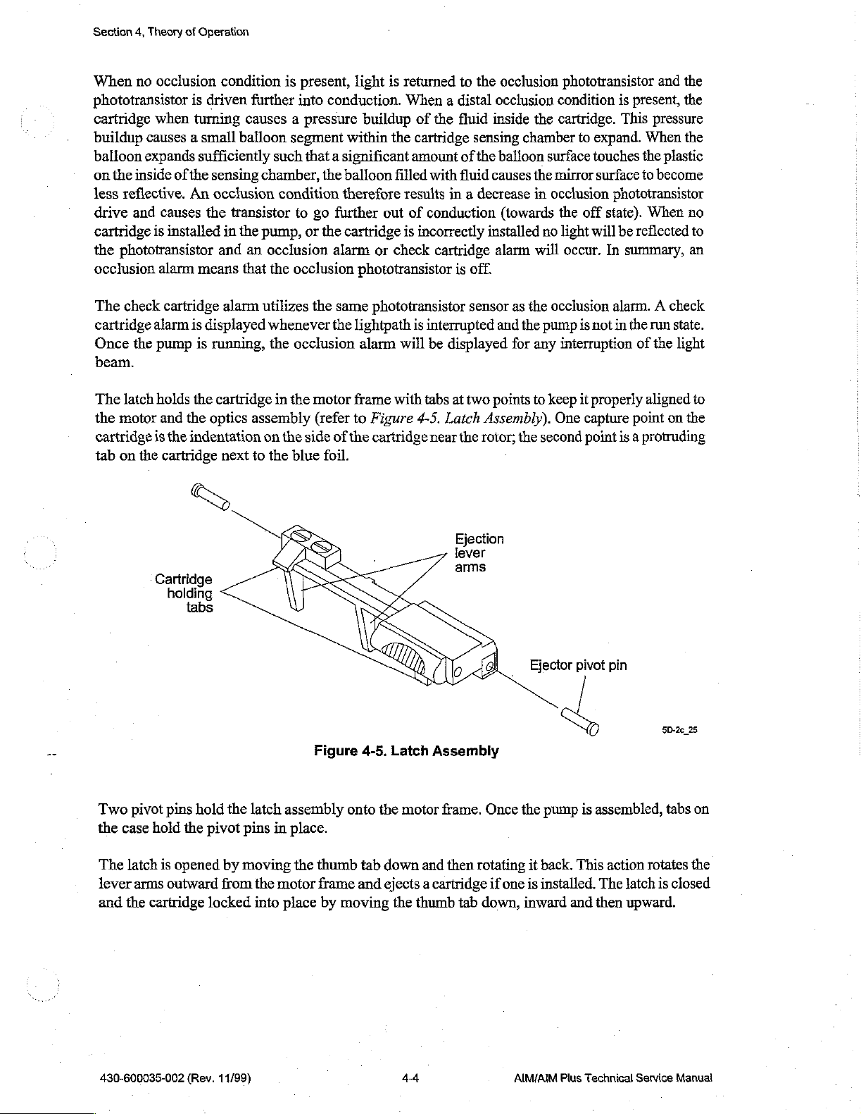
The
latch
holds
the
the
motor
and
the
cartridge
tab
on
is
the
the
indentation
cartridge next
condition
driven
turning
further
causes a pressure
balloon
sufficiently
sensing
occlusion
the
in
and
means
alarm
displayed
is
running,
cartridge
optics
such
chamber,
condition
transistor
the
pump,
an
occlusion
that
the
utilizes
whenever
the
in
assembly
on
to
the
is
present,
into
light
conduction.
buildup
segment
within
that a significant
the
balloon
therefore
to
go
further
or
the
cartridge
alarm
occlusion
the
the
occlusion
the
motor
(refer
the
side
of
blue
foil.
or
phototransistor
same
phototransistor
lightpath
alarm
frame
to
Figure
the
cartridge
is
returned
When a distal
of
the
the
cartridge
amount
filled
with
results
out
is
check
will
with
in a decrease
of
conduction
incorrectly
cartridge
is
interrupted
be
displayed
tabs
4-5.
Latch
near
to
the
fluid
inside
sensing
of
the
fluid
causes
installed
is
off.
sensor
at
two
points
Assembly).
the
rotor;
occlusion
occlusion
the
chamber
balloon
surface
the
mirror
in
occlusion
(towards
no
alarm
will
as
the
occlusion
and
the
pump
for
any
to
keep
One
the
second
phototransistor
condition
cartridge.
to
expand.
touches
surface
is
present,
This
pressure
When
the
to
become
and
plastic
phototransistor
the
off
state).
When
light
will
be
reflected
occur.
In
summary,
alarm. A check
is
not
in
the
run
interruption
it
properly
capture
point
of
the
aligned
point
is a protruding
the
the
the
no
to
an
state.
light
to
on
the
Two
the
case
The
latch
lever
and
the
Cartridge
holding
pivot
pins
hold
is
arms
outward
cartridge
tabs
hold
the
pivot
opened
locked
the
latch
pins
in
by
moving
from
the
motor
into
Figure
assembly
place.
the
thumb
frame
place
by
4-5.
onto
tab
and
moving
Ejection
Latch
Assembiy
the
motor
frame.
down
and
then
rotating
ejects a cartridge
the
thumb
tab
Once
if
one
down,
Sa
the
pump
it
back.
is
installed.
inward
is
assembled,
This
action
The
and
then
5D-2c_25
tabs
rotates
latch
is
upward.
on
the
closed
430-600035-002
(Rev.
11/99)
4-4
AIM/AIM
Plus
Technical
Service
Manual
Page 23
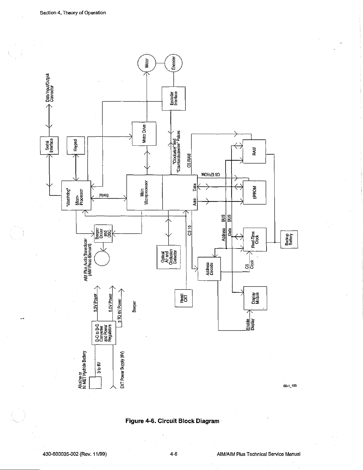
4.2
Section
4,
Theory
of
Operation
Circuit
The
heart
MC68L1IKIFN
nonmultiplexed
microprocessor
internal
paging
memory
outputs,
circuitry.
Peripherals
bus.
Each
line
display
of
additional
are
both
is
lost,
automatic
information
A
watchdog
bus
between
a
second
interfaces
Block
of
chip
select
and
chip
map
and
which
to
the
peripheral
module,
address
chip
selected
power
is
battery
will
or
the
means
to
the
Diagram
the
Abbott
(refer
address
to
address
logic,
select
system
can
be
main
device
the
decoding
supplied
switch
be
maintained
second
two
microprocessors.
of
shutting
keypad
AIM/AIM
to
and
up
allow a reduction
logic
operation.
implemented
microprocessor
has a unique
real
time
by
the
to
the
over
microprocessor
and
Plus
Figure
data
to
is
4-6.
ports.
0.5 M byte
under
software
The
as
simple D to A converters,
are
range
clock,
the
logic
is
required
main
microprocessor’s
real-time
circuitry.
even
when
communicates
The
off the
other
motor
devices
circuit
Circuit
It
also
of
external
in
microprocessor
connected
of
256K
for
clock and
The
power
main
or
actuating
via
port
is
Block
has
self-contained
memory.
extra
hardware
control,
more
te
addresses.
byte
EPROM
addressing
I/O
chip
RAM
clock
will
is
lost.
to
function
lines.
the
main
Diagram).
The
required
flexibility
also
contains
with a minimal
the
system
The
peripherals
and
the
select.
via
an
internal
therefore
the
main
of the
second
the
alarm.
microprocessor, a Motorola
The
MC68L11K1FN
paging
self-contained
four
via a common
32K
byte
display and
When
backup
keep
microprocessor
microprocessor
The
logic
paging
for
the
system.
is
permitted
pulse
amount
are the
RAM.
real-time
the
main
lithium
running
watchdog
to
allow
logic
Since
in
the
width
modulator
of
additional
address and
16
character
A small
clock,
source
of
battery and
and
the
via the
serial
is
to
microprocessor
has
the
plus
the
system
data
by
4
amount
which
power
RAM
SPI
provide
The
motor
drive
The
drive
circuit
the
motor.
will
technology
The
delivers
clockwise
motor
actually
of
counterclockwise
direction
Outputs
microprocessor.
such
There
optics
the
voltage
interface
components
At
be
greater
is
motor
speed
two
or
speed
turn
due
from
as
battery
is a DC
and
beeper.
digital
and
io
minimize
between
low
than
utilized
phase
counterclockwise
encoder
in
reverse
to
the
and
to
analog
(such
circuit
regulates
has
the
capability
motor
the
to
is
monitored
quadrature
is
or
turns,
shaft
“windup.”
optical
The
A/D
external
DC
converter
The
6V
circuits.
power
5.0V
as
the
motor
speeds,
battery
minimize
the
voltage
with a magnetic
pulses
pulse
actually
speed
of
either
applied
circuit
to
the
information
at
the
motor
by
stepping
motor
at
high
losses
Hall
encoder
and
maintaining a constant
motor
in
counterclockwise a small
the
software
air
and
converter
power
that
in
turn
Wherever
consumption.
supplied
can
compensate
occlusion
in
the
main
supply
steps
is
converted
voltages,
up
possible,
components
detectors
microprocessor
the
battery voltage
via
There
(such
microprocessor).
up
or
stepping
voltage
the
effect
interface
depending
not
number
linear
the
may
speeds
motor
encoder
circuit,
at
the
of
for
extra
are
read
and
motor
regulators
digital
are a number
as
the
back
down
be
less
than
or
flow
driver
circuit.
integral
which
on
the
direction
gearbox
turns.
output
By
keeping
counts
by
the
also
monitors
voltages
to
approximately
to
5.0V
circuitry
display
is
of
interface
module)
EMF
the
supply
the
rates.
DC
to
the
motor.
translates
of
shaft,
in
the
forward
A/D
converter
vital
and
currents.
and
3.3V
operated
circuits
across
the
voltage
battery
voltage
to
DC
The
these
rotation.
the
track
of
the
or
in
pump
parameters
6V
for
driving
for
operation
at a 3.3V
required
and
3.3V
motor.
to
drive
and
converter
encoder
pulses
to
Since
the
motor
can
number
clockwise
the
main
the
of
supply
to
supplied
AIM/AIM
Plus
Technical
Service
Manual
4-5
430-600035-002
(Rev.
11/99)
Page 24
Section
4,
Theory
of
Operation
indingAndu
201094105)
eed
ETTİ
Ris
sBOpyoeM,
pedian
105589014
00
LI
769005464
use
0000
Ozal
9010
NIV)
NR
Аден
эру
A
ta
AN
の
g
E
100008
79040
pue
PC)
воле
|
VAT
JBMO
Ji9AU0O
PUR
Asa
ç
290
|
Jewod
TROIE
A09
DIE
siojenbay
(98)
Addng
Alddng
Jamo,
4emog
1x3
JON
ANO
ION
jedesg
MTT
jepoou3
po
UB,
=
OSC,
“ee
VOSSO
1098181
pur
tendo
dy
вера
зала
‚евмрораииоо,
AVE
SO
8
Е
med
IPY
ES)
Î
1996H
DI
a
5
sna
SSOPPY
звалрру
орооеа
sna
era
Wi
[|
moud3
eur
1684
1000
so
fejdsia
ferdsia
EE
Woo
:
旨
lnpo
内
dmpeg
heyeg
È
2
430-600035-002
(Rev.
11/99)
Figure
4-6.
Circuit
48
Block
Diagram
AIM/AIM
Plus
Technical
Service
Manual
Page 25
43
Section
4,
Theory
of
Operation
Detailed
Refer
to
Section
Figure
ロロ
Figure
Figure
Figure
ロロ
Figure
Figure
Figure
ロロ ロロ
Figure
Figure
ロロ
Figure
4.3.1
CPU
9-1,
9-2,
9-3,
9-4,
9-5,
9-6,
System
Circuit
9,
Drawings,
AIM
AIM
AIM
AIM
AIM
AIM
9-7,
AIM
9-8,
AIM
9-9,
AIM
9-10,
AIM
Description
for
the
following
Analog
Microprocessor
Power
PC
PC
Plus
Plus
Plus
Plus
Plus
Schematic
and
Miscellaneous
Board,
Board,
Front
Back
Analog
Microprocessor
Power
PC
PC
Schematic
and
Board,
Board,
fold-out
(CPU)
Miscellaneous
Front
Side
Side
Back
Schematic
Circuitry
(CPU)
Schematic
Side
Side
schematics
Schematic
Circuitry
Schematic
and
PCB
drawings:
43.11
Microprocessor
The
Motorola
attached
The
68L11
utilized
range
and
operation.
Resistors
microprocessor
form a low-pass
the
microprocessor.
microprocessor
that
allow
through
The
microprocessor
can
be
microprocessor
crystal.
peripherals.
MC68L11K1FN
peripherals
microprocessor
in
conjunction
C17
and
R116
and
into
filter
has
the
microprocessor
A15).
set
up
via
is
The
E-clock,
(CPU)
are
supplied
contains
with
C16
provide
R117
the
expanded
to
supply a low
The
microprocessor
internal
also
software
typically
paging
contains
however,
microprocessor
by a 3.3V
an
internal
the
2MHz
pull
the
correct
up
the
memory
crystal,
noise
logic
controlled
to
access
memory
internal
to
issue
chip
the
crystal
can
frequency
be
U19
VDD
supply
single
Y1.
R37
loading
MODA
mode
and
of
reference
has
separate
by
beyond
chip
selects
selects
stretched
for
divided
forms
the
to
achieve
inverter
biases
and
phase
MODB
operation
to
the
internal
address
extended
its
normal
(CSPROG,
certain
by
under
software
basis
of the
minimal
(parallel
the
inverter
shift
inputs
coming
A/D
and
address
64K
CSGP2,
address
4,
or
500KHz
control
main
CPU
power
resonant)
for
operation
to
maintain
to
VDD
out
of
reset.
converter
data
lines.
lines
XA13
limitation
CSGP1
ranges.
in
The
the
to
system.
It
consumption.
oscillator
circuit
in a linear
stable
oscillator
to
program
R115
and
C43
via
VRH
input
In
addition,
through
(controlled
and
E-clock
case
allow
XA18
by
CSI0)
on
of a 2MHz
for
slower
and
the
to
the
AO
that
the
ΑΙΜ/ΑΙΜ
Plus
Technical
Service
Manual
4-7
430-600035-002
(Rev.
11/99)
Page 26
Section
4,
Theory
of
Operation
4.3.1.2
EPROM
The
main
program
memory
used,
jumper
the
the
EPROM
be
DEC
4.3.1.3
Microprocessor
The
circuit
voltage,
watchdog
microprocessor.
oscillator
reset,
microprocessor,
U20.
source
XIRQ
low,
cause
pulses
space.
A13
is
also
option
jumper
CPU
forced
JP12
first
to
pulse
to
the
or
31
DEC,
reset
to
both
issues a minimum
or
whenever
internal
should
both
microprocessors
Whenever
to
BT2
input
to
causing
the
XIRQ
on
V_PWR
The
allows
and
comes
low, thus chip
high
microprocessors
The
fail,
U18.
VDD
source.
U19.
an
interrupt
whenever
memory
EPROM
addressed.
two
not
state,
depending
different
JP11,
out
of
causing
resides
is
If
reset,
on
Supervisory
50
ms
PFI
is
to
U21
is
watchdog
since
both
will
U21
also
drops
below
The
final
Whenever
to
the
V_PWR
from
prematurely
in
the
27LV020
addressed
jumper
choices
giving a 16K
selecting
program
the
11
the
CSPROG
jumper
via
is
used,
of
wide
the
EPROM.
instructions
option).
Circuit
is
controlled
reset
pulse
whenever
less
than
approximately
pulsed
microprocessors
controls
function
PFI
microprocessor.
at
least
forces a reset
force a motor
the
power
BT2
battery
of
U21
falls
below
is
below
triggering
EPROM
the
address
XA13
window
window
will
by
the
every
in
run
off
voltage,
is
to
approximately
R51
approximately
the
lines
through
and
bank
and
be
pulsing
In
addition
to
start
microprocessor
the
VDD
1.3V. A reset
1.6
seconds
the
rare
event
off
the
same
condition,
source
and
for the
the
VOUT
provide a power
1.3V,
and
R52
3V.
XIRQ
circuit.
U15,
which
A0
through
XA17
sizes.
16
banks
low,
the
executing
voltage
that
crystal
an
RAM
the
contains
A12,
are
addressed
Normal
extended
supervisory
will
via
alarm
switches
loss
PFO
operation
of
EPROM
causing
is
the
U14
CE
address
from
the
less
than
also
be
the
WDI
microprocessor
oscillator
condition
and
power
warning
output
When
provide a voltage
C23
acts
as a filter
256K
jumper
instead.
will
memory.
and
OE
lines
highest
circuit,
the
battery
issued
unless
input
in
U19.
from
time
of
from
to
the
CPU
from
U21
divider
to
prevent
adjusted
bytes
call
When
on
will
page
U21.
from
crystal
During
the
day
clock
the
VDD
via
will
noise
of
12
is
This
for
the
all
(15
This
BT2
the
the
6805
the
go
to
4.3.1.4
RAM
The
RAM
backed
lines
is
line.
during
condition
(write
data
D7.
to
from
430-600035-002
up
A0
through A 14,
provided
The
output
low
exists.
condition).
I/O
lines
All
address
maintain
raising
by
Ul4
the
by
the
power
to
all
inputs
the
(Rev.
contains
lithium
microprocessor’s
of
U2D
conditions.
The
The
the
and
RAM’s
32K
battery
allowing a RAM
is
gated
WE
to
the
OE
is
enabled
RAM
are
data
lines
in a known
VCC
11/99)
bytes
The
interfaced
connected
supply
of
via the
CSGP2
with
RESET
chip
RAM
when
logic
memory
supervisory
address
enable
will
via
to
prevent
be
enabled
range
U2D
to
E-clock
directly
to
the
RAM
state
when
current
during
4-8 AIM/AIM
which
is
nonvolatile
circuit
U21.
The
of
00000-07FFF.
and
U12A.
the
the
RAM
whenever
is
high
to
the
microprocessor’s 8 bit
are
pulled
VDD
power
lithium
RAM
will
and
RD
battery
U2D
from
thus
RD
low
is
lost,
is
because
RAM
The
inverts
being
be
from
high
with
thus
backup
its
power
is
addressed
chip
enable
the
active
inadvertently
disabled
the
(read
pull
preventing
Plus
whenever a reset
microprocessor
condition).
data
bus
down
resistors
conditions.
Technical
supply
via
address
to
the
low
CSGP2
written
is
The
DO
through
in
floating
inputs
Service
is
RAM
to
low
eight
order
Manuat
Page 27
4.3.1.5
Time
U20
battery
reliable
by
power
enabled
by
does
for
U20,
allow
Ul2
insuring
inadvertent
4.3.1.6
Of
Day
contains a separate
backup
oscillator
the
RAM.
U16.
not
U20
so
For
loss
conditions,
by a combination
When
exist.
CSIO
then
becomes
that
U20
ANDing
is
also
powered
valid
access
Display
Clock
32.768
conditions.
function.
the
timer,
otherwise
of
A5-A11
of
the
logic
are
can
be
1000-101F.
cannot
E-clock
by
level
or
high
be
the
KHz
C20
and
C21
The
VDD
supply
it
is
also
important
lithium
the
microprocessor
low
and
CSIO
set
active
The
written
with
same
“1”
backup
during
RD
battery
conditions
battery
crystal
provide
for
battery
is
in
the
range
NAND
low
and
RD
backed
to
current
oscillator
U20
that
CSIO
low,
gate
power
signals
the
circuit
the
necessary
is
the
all
inputs
current
line
U20
is
of
1000-1FFF
U12B
conditions.
to
U20
supply
control
during
power
for
same
battery
be
pulled
drains
and
additional
chip
selected,
via
allows
in
the
as
the
inputs
loss
Section
low
power
additional
phase
backed
to a known
will
be
high.
address
provided a reset
software.
reset
to
disable
U12C
and
proper
RAM
of
and
these
time
time
devices
conditions.
4,
Theory
of
consumption
shift
to
maintain
VDD
supply
logic
state
The
CS
to
decoding
The
effective
the
U12D
sequence.
of
provided
condition
chip
NAND
Note
day
clock,
and
preventing
Operation
during
utilized
during
U20
is
address
select
to
gates
that
thus
The
display
buffers
the
nominal
display
effective
on.
U9A
resistance.
Q12,
U10A,
of
the
software.
to
average
U11B
display.
level
of
the
display
is a separate
the
data
3.3V
is
enabled
address
serves
The
and
display.
This
the
and
Q3
act
The
maximum
Q3
will
and
lines
bus
of
as a 3.3V
two
Q13.
The
pulse
pulses
together
reduce
prevent
4317
Encoder
The
encoder
phasel
decoding
counterclockwise.
Interface
integral
and
phase2.
the
pattern
self-contained
D4-D7,
system
via
U17
1020-1021
to
LED’s
that
U2A,
PW4
output
train
is
into a dc
to
display
the
contrast
oscillations.
Circuit
to
the
These
of
the
two
AO,
and
to
the
when
CSIO
for the
5.0V
are
part
U9B,
U1
is a pulse
applied
level
function
contrast
AIM
Plus
outputs
outputs,
module
EN_DISP
5.0V
bus
levels
is
low,
display.
translator
of
1B,
to a low
that
as a unity
to
the
motor
are
approximately
The
to
the
display
Q3
and
train
pass
is
directly
is
achieved
display.
contains a Hall
itis
possible
that
is
interfaced
(U17-13)
required
AS
is
high
backlight
drive
the
gate
module
associated
output
filter
gain
C56
with
and
proportional
buffer,
when
functions
90
to
determine
to
the
and
provides a logic
by
the
display
and
A6
through
to
the
display
of
O6
at a full
are
driven
components
variable
divider
to
driving
the
drain
R27,
the
the
of
as a filter
effect
encoder
degrees
out
if
the
main
board
level
for
proper
A11
are
is
enabled
5.0V
in a similar
work
to
control
duty
cycle,
R28
and
C13
duty
cycle
contrast
Q3
of
motor
is
at
to
smooth
with
phase
is
terminal
ground.
quadrature
with
turning
via
U32.
translation
from
operation.
low,
giving
by
driving
to
insure
low
manner
of
by
U9D,
the
contrast
controllable
which
function
the
waveform.
(V0)
of
Raising
out
pulses
outputs,
each
other.
clockwise
U32
The
an
Q6
on
by
the
the
from
By
or
PW2
generates a normally
buffer and
when
high.
a
lower
AIM/AIM
level
PW2
goes
Strobing
power
Plus
Technical
the
translator
low, and
encader
state
when
Service
high,
U10B
the
state
helps
its
Manual
low
and
of
reduce
strobe
going
pulse
simultaneously
both
phases
power
input
is
consumption
is
low.
4-9
that
generates a strobe
clocks
U7A
latched
into
U7A
from
and
and
the
encoder,
pulse
U7B.
The
U7B
430-600035-002
to
encoder
when
since
the
PW2
the
encoder
is
strobed
pulse
encoder
(Rev.
via
goes
is
in
11/99)
Page 28
Section
USA
pulse
U31B
4,
Theory
of
Operation
and
U8B
detect
the
CLKWISE
rises
whenever
CTRCLKWISE
direction.
counterclockwise
gearbox.
software
flow
rates.
line
followed
phase2
line
Normally
rotation,
By
subtracting
can
make
4318
Backup
U18
under
where
U18.
TCAP
frequency
circuitry
peripherals
disabled
microprocessor.
backup
Microprocessor
functions
fault
PD4
The
input
as a backup
conditions,
is
the
clock
oscillator
to
U18
can
be
to
detect
such
as
via
PAX4,
Note
microprocessor.
most
that
the
encoder
at
the
rate
of
by
at
the
the
phase2
pulse
pulse
rises
encoder
motor
usually
the
small
corrections
for the
system
U18
communicates
line,
PD2
input
to
U18
originates
independently
compared
the
keypad
and
that
with
encoder
the
alarm
the X is
or
and
is
turning
the
encoder
rising.
followed
pulse
does
as
the
number
motor
or
CPU
is
the
serial
monitors
software
circuit
serial
can
used
in
in a clockwise
pulses.
Clockwise
Counterclockwise
by
phasel
rate
whenever
turn
clockwise
motor
of
counterclockwise
“backlash”
watchdog
to
the
data
from
the
the
to
the
failures.
RS232
be
enabled
the
port
interface
the
is
stopping
to
help
main
microprocessor
output
from
main
tach
frequency
“clockwise”
Most
of
via
line
bus
(normal)
direction
rotation
rotation
pulse
rising.
motor
turns
except
due
to
counts
and
help
improve
prevent
U18
and
microprocessor
from
pulse
the
port
lines
circuit.
PAXO,
Most
totally
names
to
is
Pulses
counterclockwise
for
very
“backlash”
from
the
pump
U19
PD3
U19
phase]
from
are
importantly,
independently
signify
and
is
decoded
detected
will
small
effects
the
clockwise
flowrate
from
via
the
is
the
serial
via
its
of
the
the
encoder
utilized
the
association
issue
pulses
when
phasel
by
U31A
appear
on
or
reverse
amounts
in
the
motor
counts,
accuracy
delivering
serial
XOUT
encoder.
SPI
data
pin.
at
fluid
input
This
interface
to
interface
the
motor
can
of
the
main
with
on
and
the
of
the
low
bus,
to
The
with
be
the
43.13
Keypad
The
PBXO
rows 0 through 6 are
respectively.
level
keypad
keypad
through
when
bus
Interface
is
interfaced
BPX3
Resistors
no
key
is
conflicts
4.3.1.10
Bolus
The
via
depressed,
function
assembly
case
J1.
Switch
mounted
Both
the
U2-13
as a low
from
Interface
bolus
external
is
pulled
pass
falsely
to
the
backup
are
the
pulsed
monitored
R5-R9,
being
pressed.
in
the
event
membrane
jack
and
to a low
filter
for
R11
that
the
to
prevent
column
presence
and
Diodes
two
switch
membrane
level
triggering a remote
microprocessor
R16
keys
connect
drives
are
D5-8
of
pulses
pull
in
the
for
down
provide
same
to
the
switch
and
U2-12
noise
bolus
issues a high
picked
request.
U18
via
ports
PCX0-6
columns 0 through
on
input
port
lines
resistors
isolation
row
PC
are
connected
up
from
are
board
the
to
maintain
on
the
pressed
via
J15
in
parallel.
level
to
remote
and
ports
3,
respectively,
PCX0O
row
simultaneously.
and
PBX4.
bolus
all
row
drivers
the
remote
If
through
lines
either
R3,
R17
switch
PBX0-3.
and
PCX6,
at a low
to
prevent
bolus
jack
switch
and
and
the
is
C3
cord
430-600035-002
(Rev.
11/98)
4-10
AIM/AIM
Plus
Technical
Service
Manual
Page 29
4.3.1.11
Serial
Interface
Section
4,
Theory
of
Operation
Connections
control
to
turn
networks
resistors
outputs
from
the
current
line
out
the
RS232
for
R82Z-91
of
U30.
RS232
and
voltage
to
ESD
4.3.2
Analog
Circuits
4.3.2.1
Power
The
two
actually
will
the
check
(R30
the
Circuits
unit
is
powered
power
override
sources
be
powering
TEST_BAT
is
desired
and
R33)
battery
condition
the 4 AA
3.3V, a battery
divider
R30,
R33.
the
external
and
inputs a data
interface
protection.
are
current
U30
acts
adapter
from
by 4 AA
are
the
cells.
signal
and
the
on
the
battery
can
voltage
RS232
on
and
The
limiting
as a buffer
to
the
3.3V
U30D
cells
isolated
pump.
O1
from
the
voltage
when
be
obtained.
of
6.6V
interface
in
and
control
off.
The
diodes
and E to
D21-D30
resistors
plus
voltage
CPU
system.
properly
connected
via
D3
and
Normally,
and
O2
function
6805
microprocessor
is
read
via A to D input
the
battery
Since
will
cause a full
adapter
line
input
to
limit
via
J6
D11,
when
together
voltage
the
reference
cable
are
in.
It
also
provides
and output
clamp
the
the
current
level
translator
R78,
R80,
interface
or
so
the
by
an
that
whichever
8V
power
to
is
high.
to
8V
turn
PEA
test
is
desired, a more
to
scale
reading
made
via
J8.
5.0V
power
lines
are
all
filtered
lines
to
either
to
the
diodes
to
translate
D35
and
D36
serve
the
3.3V
CPU
power
supply
supply
supply
on
The
and
the
microprocessor’s
(FF)
is
plugged
the
load
load
is
turned
filtered
at
by
the
R30
C14.
meaningful
A/D,
J8
outputs a data
and a contro!
by
resistor/diode
5.0V
or
ground
and
the
inputs
from
the
5.0V
to
limit
the
ports.
connected
voltage
and
to
is
higher
into
the
R33
on
when a battery
By
placing a load
measure
A/D
converter
because
and
line
and
and
levels
output
J13.
The
will
pump,
it
whenever
of
is
of
the 2/1
A/D
input
PE6
R12
and
C11.
This
C12
supply
should
determine
reference
The
pump’s
or
8V
batteries.
MOSFET
flyback voltage
charge
VFB
causing
divider
control
when
pulsing,
power
Shottky
go
to
whether
input
from
The
transistor
up
towards
input
C6
to
to
set
system.
the
unit
since
supply
diode
5.0V/2
6.6V.
main
the
to
U4
start
the
is
will
monitors
input
to
the
This
input
the
3.3V
to
the
A/D
power
power
converter
is
D9
running
the
drive
supply)
U13A
created
the
flyback
to
approach
to
discharge
output
prevents
VFB
pin
then
flow
below
the
voltage
should
read
A/D
converter
can
supply
converter.
supply
voltage,
on
voltage V PWR
is
is a step
on
and
at
the
anode
voltage.
approximately
through
from
batteries.
will
now
through
the
external
of
the
full
scale
input
be
used
to
is
within
converted
up
switching
off,
causing
of
D9,
When
the
while
C7
flowing
When
be
L1
and
from
pulled
supply
8V
supply
(FF)
PES,
check
to
approximately
causing
Cé6’s
1.3V,
load
causes a phase
the
unit
D9
as
provided
for a 9.9V
which
for
proper
specification,
(which
regulator
current
current
voltage
then
on
the
6-8V
the
6-8V
is
running
to a higher voltage than
to
the
6-8V
supply
should
operation
can
either
controlled
to
flow
to
is
sufficiently
the
EXT
supply
lead
supply
on
supply,
voltage.
by
voltage.
read
since
the
be 3 to 6 V
6.5V
when
through
flow
output
line.
to
prevent
to
the
the 8 V
resulting
voltage
divider
Divider
full
scale
of
the
5.0V
3.3V.
supply
from
the
unit
by
U4.
U4
L1.
When U13A
through D9
high,
however,
of
U4
R14
and
“hunting”
lower
supply
power
1.3V.
in
supply,
The
an
and
filter
R32,
R21,
R22
and
if
the
5.0V
supply
supply
is
drives N channel
thus
continues
R15
output
as
well
serves
the
running
causing
form a voltage
of
voltage
U4
current
AA
batteries
shuts
to
cause
pulsing,
the
voltage
V_PWR
will
from
as
on
off,
C6
not
voltage
the
the
one
as
a
to
the
be
the
AIM/AIM
Plus
Technical
Service
Manual
4-11
430-600035-002
(Rev.
11/99)
Page 30
Section
The
5.0V
to
transzorb
ofa
4,
Theory
6-8V
supply
supply.
all
devices
clamping
malfunction
“supercap”
capacitor
of
The
capable
approximately
the
couples
provide
C53
is a much
circuit
is
ON. Q14
Q15.
running
This slow
in
order
discharged
reset
Without
can
remain
intermediate
inputs.
voltage
an
orderly
following
is
driven
C53,
therefore,
on
batteries
charging
to
prevent
when
prevents
the
rapid
in
state
larger
multiple
Operation
is
regulated
5.0V
is
of
functioning
diode
in
U3
which
that
50mA,
maximum
from
power-down
(1F
loss
of
AC
when
is
only
connected
scheme
the
low
RESET
resets
discharge
an
intermediate
inputs
to
5.0V
by a linear
further
is
C5
supercap)
which
could
regulated
clamps
at
3.3
the
cause
by
V.
its
charged through R13
to
reduce
to
the
5.0V
bus
sequence.
capacitor
power.
Q15
“fast”
is
battery
goes
C53
is
ON,
charged
to
J6,
C53
utilized
trip
high
to
via
is
whenever
is
keep
point
Q17
from occurring
of
these
capacitors,
state
for
could
cause
high
regulator
another
C8
filters
output
output
via
the
load
upon
loss
that
is
charged
there
via
R150
charged
the
peak
from
being
and
Q16,
and
especially
long
periods
supply
current
U3
regulator
the
output
voltage
voltage
the
on
of
of
to
5.0V
the
power
utilized
through
reduces
current
is
sufficient
when
power
more
slowly
current
reached
respectively.
lithium
C53,
as
drains, similar
for
use
by
U6
to
3.3V
of
U3
U3
at
approximately
go
out
of
supply.
5.0V
regulator
to
allow
to
provide
limiting
voltage
is
present
via
R155
drains
on
prematurely.
Discharging
battery
the
inputs
the
capacitors
all
components
operation
for
stable
regulation.
R13
limits
charging
during
time
for
power
to
the
resistor
at
J13
at
J13.
current
the
battery
Both
standby
to
the
RAM
are
discharging.
to
the
condition
requiring
to
supply
operation.
5.0V
Capacitor
in
D10
the
current
power-up.
the
CPU
system
CPU
and
R150
when
to
drive
the
When
the
limiting
as
low
C5
both
current
resistor.
as
possible
and
capacitors
quickly.
and
timer
of
a
VDD
isa
event
C5
is
a
to
D13
to
alarm
Q14
base
of
pump
is
C53
are
at
chip
These
floating
4.3.2.2
Audible
The
connected
oscillator
alarm
processor’s
control.
audio
Under
output
pulses
high,
Whenever
high,
U35B’s
the
audio
a
voltage
Alarm
audibie
alarm
to
the
circuit,
signal
will
PW3
Increasing
transducer.
normal
of
the
U35B
high.
U26C
Q7
turn
ON,
the
the
backup
output
transducer
level
approximately
the
audio transducer.
power
sounding
when
switch
when
the
unit
is a small
circuit
therefore
originate
conditions,
ALARM
alarm
goes
from
2KHz
is
turned
the
is
deliberately
board
output.
the
duty
low,
so
is
held
causing
line
circuit
high,
drive.
approximately
at
approximately
U35D
off
power
electromagnetic
via
J12.
The
these
are
provided
in
the
68L11
The
PW3’s
cycle
the
ALARM
that
U10F’s
high,
thus
drive
from
consisting
thus
disabling
U11C
from
to
the
is
part
the
(main)
duty
PW3
line
output
U26A’s
audio
watchdog
of
gate
ofan
5/3
50%
and
U35C
together
and
reset
condition
switch
is
turned
turned
off.
audio
transducer
audio
transducer
on
the
circuit
microprocessor.
cycle
and
(up
to a point)
from
the
watchdog
is
high.
output
transducer
U11C,
U26B
RC
volts
duty
off
pulses
microprocessor
U26C
and
oscillator
to
10/3
cycle,
prevent
is
reached.
and
reset
(piezo
does
board.
The
frequency
causes
microprocessor
Gate
U26B
in
sync with
plugged
is
and
associated
preventing
circuit
that
volts.
U26C
which
in
the
backup
This
occurs,
to
element
not
contain
For
normal
alarm
drive
can
be
changed
an
increase
is
thus
enabled
PW3.
into
J12.
high,
and
components
PW3
from
charges
outputs a square
turn
drives
alarm
from
scheme
prevent
prevents
the
on
the
its
alarm
is
provided
under
in
loudness
is
low,
every
When
gate
U35C’s
will
having
and
discharges
U26A
and
occurring
alarm
AIM)
which
own
driver
conditions,
making
U26A
be
any
Q7
the
alarm
from
the
by
this
software
of the
the
time
PW3
pulses
output
enabled.
effect
C41
wave
to
drive
when
from
sounding
is
or
is
on
to
of
the
430-600035-002
(Rev.
11/99)
4-12
AIM/AIM
Plus
Technical
Service
Manual
Page 31

4.3.2.3
Air
and
Occlusion
Port
PA4
pulses
turned
provide
Because
will
occlusion
close
LED’s
respectively,
in
collector
input
to
read
on
additional
the
flow
to
the
pulse,
the
cartridge.
of
PEO.
the
occlusion
by
A/D
by
U9C’s
pulsed
through
detection
emitter
go
the
When a cartridge
input
4.3.24
Motor
Drive
Optics
high
periodically
output
voltage
voltage
R59
are
current,
the
air
and
into
conduction,
When
air
transistor
phototransistor,
PE1.
Circuit
going
drop
amplitude
(approximately
connected
the
occlusion
air
is
present
will
is
present
Interface
for a relatively
low.
Diodes
to
result
across
40mA).
in
series
pulsed
phototransistors,
depending
in
pulse
to a low
with
and
its
collector
D19
in a reference
R59
Two
to
J9-1
current
through
on
the
the
cartridge,
level.
no
occlusion
will
short
duty
and
D20
across
is
maintained
separate
and
2.
Since
the
whose
amount
maximum
The
of
level
condition,
pulse
to
Section
cycle.
When
PA4
along
with base
R59
of
approximately
constant, a constant
LED’s,
LED’s
collectors
light
of
one
the
collector
is
returned
light
the
pulse
for
maintained
are
connected
via
will
is
read
maximum
the
lowest
level.
4,
Theory
of
Operation
pulses
high,
emitter
drop
3.2
current
air
and
the
other
current
of
Q11
constant.
to
J9-3
the
sensing
be
returned,
via
light
A/D
will
be
chambers
and
converter
returned
The occlusion
Q9
is
of
Q11
volts.
pulse
for
is
very
When
and
4,
the
level
is
The
pump
circuit
battery
641
(approximately
cycle.
same
U28
output
‘When
are
charges
continues
needed
current
allows
The
or
supply
switching
When
time,
the
ON.
U25A
to a -5.0V
U28
and
shut
OFF.
C34
to
flow
to
allow
to
continue
voltages
speed
input
voltage.
regulator
1.3V)
EXT
output
serves
U27A
When
up
the
much
to
microprocessor.
proportional
U9E
is
level
at
inverting
decreases
to a lower
form a summing
U23A.
motor
to
the
powered
C36.
by
The
amplifier
in
amplitude.
value,
junction
C33
provides a small
servo
system
has
the
capability
The
U24.
the
EXT
of
U24
pulses
of
U25A
as a voltage
to
V_PWR
are
ON,
these
transistors
to a voltage
through
This
output
causing
motor
to
flow
higher
the
motor
pulse
duty
the
U23A.
and
D17,
to
through
width
cycle
5.0V
of
U11A
As
As
U23A
the
motor
that
minimize
of
driving
pump
circuit
When
goes
level
the
the
output
high,
low
level
swing
current
VFB
of
U24
N.channel
(to
translator,
to
through
turn
level
determined
L2
and
D18
after
run
at
voltages
L2
when
than
the
supply
control
circuit
modulated
of
PW1.
At
100%
supply.
sums a portion
amount
is
summed
the
output
output
drive
U11A
decreases
voltage
of
phase
“hunting”
the
motor
either a higher
uses a buck-boost
of
U24
input
pulses
approximately
properly
off, a flyback
lower
U28
voltage
is a pulse
serves
with
of
of
at
approximately
MOSFET
-5.0V),
converting
drive
the
L2
begins
to
voltage
by
the
speed
the
drive
transistors
than
the
supply
turns
ON.
The
to
be
delivered
width
pulse
is
averaged
duty
cycle
the
as a noninverting
the
output
of
U11A
increases
in
amplitude,
to
increase
the
motor
lead
compensation
to
voltage
effects.
or
configuration
is
lower
than
50K
Hz
transistor
gate
increase
U27A
thus
driving P channel
the 0 to
appears
and
of
U28.
linearly
torque
are
turned
5.0V
at
voltage.
flyback
modulator
voltage
by
voltage
to
the
output
R77
and
across
buffer
U23B
and a -5.0V
in
amplitude,
the
VFB
input
maintain
servo
with a portion
to
maintain
lower
voltage
controlled
the
is
until
the
requirements.
off.
D17
motor.
C36
C36
for the
the
of
control.
by
internal
at
up
to a 50%
driven
swing
of
U27A
anode
Transistor
is
needed
at
the
anode
PW1
from
to a D.C.
will
be
D.C.
offset
output
U24
will
R66
of
the
voltage
the
stability
ON.
MOSFET
U24
of
5.0V,
voltage,
than
the
the
MAX
reference
duty
At
the
EXT
and
U28
D18
and
Current
U28
is
to
allow
of
D18
the
main
level
since
command
via
of
U23A
be
pulled
and
R68
from
of
the
AIM/AIM
Plus
Technical
Service
Manual
4-19
430-600035-002
(Rev.
11/99)
Page 32

Section
The
U23B.
torque
the
maintain
of
when
the
U23A
The
By
turning
4,
current
The
load
proper
MTR_ON
PA6
5.0V
Theory
of
Operation
through
output
ratio
the
decreases,
is
to
of
on
the
motor
via
speed
of
signal
high.
When
approximately
off
the
the
motor
U23B
can
increases,
U23A
to
the
motor
forcing
from
U34B
-5.0V,
switched
is
sampled
be
sampled
the
output
cause
the
constant.
the
output
the
microprocessor
is
5.0V
drive
on, a switched
using a charge
when
by
R57
by
the
of
output
As
the
voltage
the
motor
and
converted
A/D
converter
U23B
increases.
drive
voltage
output
voltage
to
the
PA6
causes P channel
5.0V
is
supplied
pump
technique,
is
not
running,
to a voltage
as
R67
to
increase
of
U23B
motor
to a higher
to
power
filtered
U22,
for
by
and
R65
by
increases,
MOSFET
U23
use
in
is
conserved..
which
C54
sum
just
the
level.
and
U24.
the
motor
is
amplified
and
R153.
U23B’s
the
U34B
output
right
mount
output voltage
to
go
U22
converts
drive
by
As
the
in
to
ON,
circuit.
430-600035-002
(Rev.
11/99)
.
4-14
AIM/AIM
Plus
Technical
Service
Manual
Page 33

Section
5
Maintenance
This
section
designed
O
Qi
Q
contains
to
meet
Operation
The
PVT
replacement
Preventive
As
part
conducted
Diagnostics
The
PVT
malfunctioning
cleaning
the
Verification
must
of
Maintenance
of a preventive
periodically
can
be
following
be
performed
pump
assemblies
used
pump.
and
instructions
needs:
to
verify
or
maintenance
or
per
hospital
for
diagnostic
Service
and
the
performance
proper
components,
schedule,
procedures.
purposes
pump
it
during
verification
operation
is
recommended
the
troubleshooting
Tests
test
after
any
that the
(PVT).
repair
PVT
of
a
or
be
The
PVT
is
AJM/AIM
Plus
Technical
Service
Manual
5-1
430-600035-002
(Rev.
11/99)
Page 34

Section
5.1
5,
Maintenance
and
Service
Tests
Cleaning
The
pump
Establish a routine
WARNING:
Disconnect
CAUTION:
fluids
CAUTION:
components
solutions
Do
benzyl]
CAUTION:
the
the
Abbott
or
not
use
ammonium
outside
pump.
Laboratories
the
case
exterior
the
To
avoid
cleaning
Some
made
not
recommended
compounds
Do
not
surface
Using
Pump
and
schedule
pump
from
mechanical
solutions.
cleaning
from
chloride.
sterilize
of
the
abrasive
may
cartridge
for
cleaning
AC
some
containing
by
pump
result
channel
power
or
and
plastic
by
Abbott
heat,
only.
cleaners
in
should
the
pump.
prior
to
cleaning.
electronic
sanitizing
materials.
Laboratories
combinations
steam,
Do
or
product
damage,
ETO,
not
use
cleaning
damage.
be
kept
clean and
do
compounds
Using
abrasive
may
of
isopropyl
or
radiation.
abrasive
solutions
not
immerse
may
cleaners
result
alcohol and
Apply
cleaners
not
free of
in
contamination.
pump
slowly
or
product
disinfectants
or
materials
recommended
in
any
degrade
cleaning
damage.
dimethyl
to
on
by
CAUTION:
directed
solutions
CAUTION:
needles,
Cleaning
Vesphene®
Manu-Klenz®
Formula
Super
Household
in
etc.,
C™
Edisonite®
To
avoid
the
table
vary;
bleach
consult
Never
to
Solution
Ilse
use
clean
pump
on
the
the
sharp
the
pump.
Calgon
Calgon
Diversey
S.
Various
M.
Edison
Vestal
Vestal
damage,
following
manufacturer
objects
Table
Manufacturer
Corporation
Chemical
page.
such
5-1.
Cleaning
Laboratories
Laboratories
cleaning
The
for
specific
as
pens,
Solutions
Co.
solutions
disinfecting
pencils,
Per
manufacturer's
Per
manufacturer's
Per
manufacturer's
Per
manufacturer's
Per
hospital
part
bleach
should
information.
procedures;
in
be
used
properties
fingernails,
Preparation
recommendation
recommendation
recommendation
recommendation
do
not
ten
parts
water
only
of
cleaning
paper
exceed
as
clips,
one
430-600035-002
(Rev.
11/98)
5-2
AIM/AIM
Plus
Technical
Service
Manual
Page 35

Section
5,
Maintenance
and
Service
Tests
Q
Clean
-
OPTICS
Clean
appropriate
affected
the
SURFACES
pump
the
exposed
by
Figure
as
follows:
surfaces
cleaning
the
appropriate
5-1.
of
solution
cleaning
PUMP
Cartridge
the
pump
listed
SIDE
VIEW
Channel
with a soft,
in
Table
5-1.
solutions.
,
Detail
lint-free
Cleaning
cloth
dampened
Solutions.
The
with
pump
5D-5.25
the
is
not
-
Note:
CAUTION:
cause
the
-
-
-
Note:
could
Ifthe
Not
Do
pump
Clean
optics
Wipe
pump
Dry
the
Wiping
affect
pump
has
all
cleaning
not
sterilize
to
the
cartridge
surfaces
the
solution
in
fluid.
pump
the
the
performance
been
in
an
solutions
by heat,
malfunction.
channel
(refer
to
Figure
from
the
Assure
after
pump
that
cleaning.
free
isolation
on a regular
pump
the
of
cleaning
of
the
area,
are
disinfectants;
steam,
5-1.
Cartridge
surface
optics
pump.
disinfect
check
ETO,
or
basis.
Use a moistened
Channel
with a moistened
surfaces
solutions
are
free
helps
the
external
the
product
radiation,
Detail).
cloth.
of
detergent
prevent
surfaces
as
cotton
detergent
of
labeling.
these
swab
Do
not
film.
buildup,
the
pump.
methods
to
clean
immerse
which
may
the
the
AIM/AIM
Plus
Technical
Service
Manual
5-3
430-600035-002
(Rev.
11/99)
Page 36

Section
5,
5.2
Maintenance
and
Service
Tests
Inspecting
Periodically
cosmetic
components,
5.2.1
Pump
Inspect
A
Front
perform
defects.
or
accessories
Inspection
the
following
Case
Inspect
Inspect
Inspect
Verify
Inspect
Verify
the
Also
for
display
the
smooth
bolus
Pump
an
external
inspect
components:
cracks
window
keypads
power
and
presence
the
as
required.
or
breakage.
for
physical
switch
power
and
legibility
and
Accessories
inspection
pump
and
LCD
after
for
damage.
operation.
jacks
for
excessive
of
BOLUS, 8 VDC,
of
the
repair
damage.
pump
wear
and
accessories
or
during
or
damage.
and
cleaning.
ON/OFF
for
damaged
Replace
labels.
parts
and
assemblies,
Q
Back
Inspect
Verify
Inspect
Verify
Motor
Verify
Inspect
Rotate
Verify
Verify
Inspect
Verify
Install
seats
Inspect
Case
Frame
over
for
cracks
VOID
presence
label
to
verify
Assembly
motor
frame
to
insure
motor
shaft
presence
dowel
pin
to
insure
presence
test
cartridge
optics
optic
carrier
or
breakage.
is
intact.
presence
and
legibility
(includes
is
free
that
motor
clockwise
of
motor
presence
latch
engagement
and
condition
to
verify
carrier.
for
of
closure
of
operating
Optics
from
scratches,
shaft
extension
to
insure
mount
screws.
and
condition.
of
cartridge
latch
excessive
hardware.
and
and
discoloration,
is
smooth
operates
smoothly
hold-down
hold-down
scratches
and/or
serial
number
Latch
Assemblies)
present
and
rotation.
tab
engages
contamination.
labels.
or
contamination.
firmly
attached
without
tab.
binding.
cartridge
tab
te
motor
and
correctly
shaft.
Verify
430-600035-002
presence
(Rev.
11/99)
of
optic
retention
screws.
5-4
AIM/AIM
Plus
Technical
Service
Manual
Page 37

Section
5,
Maintenance
and
Service
Tests
Battery
-
-
-
-
-
Compartment
Verify
Inspect
Verify
Inspect
Install
presence
condition
batteries,
legibility
door/case
mode.
5.2.2
Accessories
Inspect
the
accessories
다
Rechargeable
-
Ensure
-
Slide
the
that
the
OFF
of
battery
of
battery
of
battery
interface
move
power
Inspection
as
follows:
Battery
the
ON/OFF
position.
pack
switch
Pack
slides
door
and
polarity
contacts.
for
cracks
switch
fully
into
to
ON
and
condition
labels.
and
breakage.
to
ON
position
place
and
verify
that the
of
PCB
that
contact.
and
insure
it
locks
unit
powers
unit
firmly
to
on.
enters
the
pump.
Slide
self
diagnostic
the
switch
to
AC
Power
- - Check
-
Remove
connector
-
Slide
-
Verify
AC
OFF
Remote
-
Confirm a connection
-
Verify
-
Verify
Printer
-
Inspect
-
Inspect
-
Inspect
Supply
the
cord
the
fits
the
ON/OFF
that
the
power
LED
position.
Bolus
Cord
that
the
that
bolus
and
Printer
the
printer
the
connections
the
printer
batteries.
firmly
alarm
for
damage
Connect
into
switch
LED
(next
to
and
Switch
and
connector
plug
pin
Cable
cable
to
following
or
the
to
(next
the
check
fits
is
for
the
fraying;
the
power
ON
plug
firmly
not
damage.
pump
the
confirm a connection
AC
power
jack.
and
verify
to
the
alarm
icon)
flashes
the
cord
into the
bent.
and
manufacturer’s
adapter
that the
icon)
on
and
and
bolus
bolus
jack.
printer;
check
recommendations.
to
the
unit
powers
flashes
remains
switch
the
to
the
power
on,
then
lit.
for
damage.
pins
adapter
jack.
on.
off.
Slide
for
damage.
-
box.
Verify
Verify
the
switch
that
that
the
the
to
the
AIM/AIM
Plus
Technical
Service
Manual
5-5
430-600035-002
(Rev.
11/99}
Page 38

Section
5,
5.3
Maintenance
and Service
Tests
Performance
The
PVT
Supply
pump’s
The
PVT
PVT,
copy
For
more
during
Q
Electrical
Uses
(ATP).
A
Delivery
Verifies
“wet”
U
Optics
Verifies
consists
Test,
memory.
Form,
the
information
the
PVT,
the
and
the
located
form
refer
Test
pump’s
Test
the
test
that
Test
correct
of
motor
Verification
five
tests:
the
Electrical
Burn-In
and
measures
Test.
at
the
end
fill
in
the
regarding
to
Section
software
operation
fluid
operation
The
Preparation
of
this
pump
any
alarms
6,
Troubleshooting.
diagnostic
through a “dry”
delivered.
of
the
optics
Test
Test,
section,
model
(AIM
that
mode
by
generating
(PVT)
the
Delivery
for
Use
procedure
may
be
used
or
AIM
occur
or
other
to
perform a final
test
that
measures
occlusion
Test,
to
record
Plus)
abnormal
the
Optics
clears
the
testing data
the
PVT
and
serial
number.
performance
acceptance
motor
turns
and
air-in-line
Test,
results.
test
procedure
or
through
alarms.
the
Current
from
To
use
detected
the
the
a
A
Current
Verifies
©
Burn-In
Verifies
This
requirements
O
Preparation
Clears
for
patient
CAUTION:
previously
to
assure
in
this
manual,
the
PVT.
Supply
proper
Test
correct
test
is
not
the
NVRAM
use.
Many
performed;
accurate
stop
Test
current
operation
required,
to
determine
for
Use
and
test
therefore,
results.
testing,
drain
of
but
is
if
error
steps
If
test
rework
for
acceptable
the
pump
recommended
this
test
is
logs.
Always
are
dependent
all
tests
results
the
battery
over
24
hours
by
the
required.
complete
are
to
for a step
pump,
and
life.
without
manufacturer.
this
on
be
performed
do
start
section
the
not
testing
alarms.
correct
meet
Consult
before
outcome
in
the
the
parameters
from
facility
releasing
the
of
order
the
presented
beginning
pump
steps
given
of
430-600035-002
(Rev.
11/99)
5-6
AIM/AIM
Plus
Technical
Service
Manual
Page 39

5.3.1
PVT
The
PVT
The
optics
Equipment
requires a power
test
block
and
source,
turns
counter
the
electrical
are
test
setup,
available
and
the
as
alternatives
Section
wet
to
5,
Maintenance
test
setup
wet
testing.
and
Service
as
detailed
Tests
below.
Equipment
O
A
Qi
Di
Equipment
ロロ
ロロ
ロロ
ロロ
ロロ
available
Digital
Seiko®
desired),
Four
AA
“Wet”
-
Quick-Load™
-
20
-
Fluid
5-8V
microbox
Battery
AC
substitution
3.6
oz-in
Optics
Turns
Printer
Cartridge
AC
power
Quick-Load™
available)
from
multimeter
DPU411,
(refer
to
batteries
test
setup
mL
graduated
reservoir
available
substitution
test
counter
cable
from
with
cable
torque
block
with
for
housing
supply
cartridge
standard
(DMM),
DPU414
System
(if
optics
cartridge
cylinder
Abbott
12V
block
brake
fixture
12V
power
Seiko
or
(for
use
list
13586
set
sources:
Fluke®
or
Kodak
Operating
block,
power
Kodak
turns
set
w/0.2mL
Laboratories
supply,
with
supply
printers
with
turns
(if
desired
(for
“wet”
Model
77,
Diconix
Manual
counter,
graduations
(refer
battery
18V
power
and
cartridge
(if
counter
for
24-hour
test
if
or
equivalent
150
Plus
for
Printer
or
torque
to
the
Spare
substitution
supply
housing
printout
and
optics
of
current
burn-in
block,
printer
Setup)
electrical
turns
brake
Parts
block,
supply
test)
counter,
(if
are
Price
and
test
test)
printout
not
AC
of
available)
List):
substitution
desired)
or
torque
electrical
test
cable
brake
are
not
5.3.2
Electrical
This
test
uses
(ATP).
exceptions:
Plus
specific
5.3.2.1
Recording
The
step
printed
5.3.8)
information,
AIM/AIM
The
the
contains
test
sections.
pump
will
of
the
electrical
at
the
as
part
Plus
Technical
AIM
an
end
of
if
Test
the
pump’s
and
Keypad
Encoder
Test
display a message
of
the
test
desired.
software
AIM
Test
Test
Results
test
is
completed.
the
test.
record.
Service
Manual
Plus
for
This
diagnostic
share
the
while
the
asking
printout
There
AIM
AIM
These
is
also
the
same
Plus
does
you
to
answers
may
space
mode
to
Service
requires
not.
These
respond
are
be
attached
provided
5-7
perform a final
Mode
an
exact
sequence
differences
YES
for
logged
to
on
to
the
the
acceptance
Diagnostic
PASS
or
the
pump’s
PVT
Data
PVT
Data
with
of
key
presses
are
noted
again
NO
for
FAIL
memory
Form
(refer
Form
for
430-600035-002
test
procedure
the
following
and
under
after
and
may
to
Section
recording
(Rev.
AIM
the
each
be
this
11/99)
|
Page 40

Section
5,
Maintenance
5.3.2.2
Test
Setup
For
test
setup
1.
Connect
2.
Connect
3.
Insertbattery
closes
4.
Insert
barrel
5.
Attach
diagram,
microbox
the
over
inserted
barrel
12V
power
and
Service
Tests
refer
to
to
the
DMM.
12V
power
substitution
plug
plug
block).
from
from
supply
supply
block
battery
EXT
Figure
5-2.
to
the
into
the
substitution
POWER
Basic
12V
IN
pump’s
block
jack
of
Equipment
jack
on
the
battery
microbox
compartment
into
BATT
Setup.
microbox.
BLOCK
to
AC
power
DMM
(battery
jack
jack
set
to
door
on
of the
300
only
the
microbox.
pump.
mV
partially
430-600035-002
(Rev.
Battery
11/99)
door
Figure
5-2.
Basic
Pump
Eguipment
Setup
AIM/AIM
Batter
substitution
block
Plus
Technical
Service
6F4
Manual
6
Page 41

6.
Make
-
Turn
-
Turn
-
Turn
5.3.2.3
Entering
The
Service
Ifthe
steps
will
complete
100
will
occur,
then
power
the
following
the
voltage
filter
the
Test
are
not
the
which
on
again
adjustments
pump
power
selector
switch
Service
Mode
to
Test
is
entered
completed
self-test
as
indicates a stuck
and
repeat
selector
to
8V.
SLOW.
Mode
by
as
directed,
usual.
the
to
the
microbox
to
EXT.
completing
the
If
the
[OPTIONS]
key.
In
steps
as
indicated.
POWER.
the
pump
either
switches:
steps
below
will
not
key
is
case,
power
Section
enter
the
held
down
off
5,
during
the
Service
too
the
pump,
Maintenance
initial
Test
Mode
long,
System
wait
and
Service
Tests
self-test.
but
instead
Error
Code
several
seconds,
Power
on
the
UNIT
IN
TIME
DDD,
KEYPAD
RELEASE
TIME
DDD,
ENTER
SEQUENCE
pump
SELF-TEST
PROGRESS
IS
MMM
IS
MMM
KATA
5.3.2.4
Selecting
01
02
03
USE
SELECT
1
2
PRESS
the
VERSION
CLEAR
CLEAR
*
BOARD
FINAL
PUMP
SERIAL
RE
NO
##:##
DD,
CHECK
KEY
##:##
DD,
THE
NUMBER
Final
EXT RAM
ERR
FOR
ATP
TEST
TEST
NUMBER
TO
to
initiate
XM
YY
XM
YY
LOCK
ATP
+
LOG
MORE
TEST
EXIT
the
self-test.
After
Immediately
Continue
the
first
Continue
Release
pump's
AIM:
AIM
Test
Press
the
line
Press
Enter
Press
approximately
after the
to
hold
[OPTIONS]
two
lines
and
to
hold
the
[OPTIONS]
list
number
[1] [3]
Plus:
[1] [3] [9]
[2]
[1]to
to
enter a selection).
[2]
to
select
the
pump’s
[NO]
to
to
[0] [31
select
ATP
FINAL
serial
exit.
12-15
beep
the
beeper
key
until
and
access
[8]
[6]
[7]
TESTS
number
seconds
press
while
the
use
the
the
TEST.
the
and
hold
this
alarm
sounds.
following
numeric
Service
(you
(on
do
back
Test
nothave
pump
will
the
[OPTIONS]
message
display
keypad
Mode.
label).
beep
flashes
appears:
to
enter
to
be
displaying
once.
key.
on
the
AIM/AIM
Plus
Technical
Service
Manual
5-9
430-600035-002
(Rev.
11/99)
Page 42

Section
5.3.2.5
Set
5,
Clock
Maintenance
TIME
SAT,
AUG
*
KEY
PRESS
_
SET
‘YES’=
‘NO’ = FAIL/QUIT
or
5.3.2.6
Software
VERSION
MAIN
SAFETY
PRESS
VERSION
\YES'=
‘NO’ = FAIL/QUIT
or
and
IS
10:42
03,
TO
CHANGE
NO TO
CLOCK
PASS/NEXT
‘BACKUP’
Version
NUMBERS
NO
TO
#
PASS/NEXT
‘BACKUP’
Service
Tests
AM
96
EXIT
Verification
+
tés
Poř
EXIT
If
time
and
date
Ifa
change
instructions
[NO]
If
using
Press
the
FINAL
[BACK-UP]
Record
PVT
Press
the
FINAL
to
exit
the
[YES]
the
Form.
[YES]
is
necessary,
on
when
PVT
to
to
MAIN
to
ATP,
are
correct,
the
display
the
Form,
indicate
ATP
(Acceptance
repeat
and
indicate
or
press
press
press
to
clock
record
PASS
the
test.
SAFETY
PASS
[BACK-UP]
[NO]
the
[OPTIONS]
enter
is
correct.
the
results.
and
go
software
and
go
to
the
correct
to
the
Test
to
to
the
exit.
key
and
information.
next
test,
[NO]
Procedure),
version
repeat
next
numbers
test,
[NO]
the
test.
follow
the
Press
to
exit
or
press
on
to
exit
the
5.3.27
Supply
Check
SUPPLY
EXT
AC
REG
SV
PRESS
SUPPLY
‘YES’=
‘NO’ = FAIL/QUIT
or
CHECK
#.##V
#.##V
NO
TO
CHECK
PASS/NEXT
‘BACKUP’
###
###
EXIT
PLEASE
check.
Verify
Verify
Press
[NO]
If
using
Press
[YES]
the
FINAL
WAIT
PRESS
the
EXT
the
REG
the
NO
AC
to
exit.
PVT
to
indicate
ATP,
will
TO
reading
5V
reading
Form,
or
press
display
EXIT
while
appears
is
is
record
PASS
[BACK-UP]
the
pump
when
the
7.60 - 8.40V,
4.80 - 5.20V
the
results.
and
go
to
the
next
to
repeat
performs
check
is
complete.
test,
[NO]
the
test.
the
supply
to
exit
430-600035-002
(Rev.
11/99)
5-10
AIM/AIM
Plus
Technical
Service
Manual
Page 43

5.3.2.8
Display
Test
012345678
GHIJKLMNOPORSTUV
9ABCDEF
WXYZabcdefghijkl
mnopgrstuvwxyzm
DISPLAY
“YES'=
‘NO’
=
or
TEST
PASS/NEXT
FAIL/QUIT
‘BACKUP’
5.3.2.9
Contrast
ADJUST
BACKLIGHT
Adjust
0.04V
PRESS
ADJUST
0.04V
BACKLIGHT
PRESS
CONTRAST
NO
TO
CONTRAST
NO
TO
OFF
EXIT
ON
EXIT
Verify
Press
If
Press
the
Use
the
Press
the
[NO]
using
[YES]
FINAL
the
screen
[CHANGE]
recommendation
Press
[5]
“ON”,
Press
[2]
backlight
display
to
the
PVT
to
ATP,
arrow
fades
and
and
goes
appears
exit.
Form,
indicate
or
press
keys
to
as
the
to
for
highest
verify
that
verify
that
off
after
as
shown
record
PASS
[BACK-UP]
increase
voltage
set
the
contrast).
the
backlight
the
message
five
seconds
Section
5,
Maintenance
here.
the
results.
and
go
to
to
and
decrease
increases.
contrast
to
stays
switches
.
the
next
repeat
the
0.04V
on
and
Service
test,
[NO]
to
the
test.
voltage.
Verify
(manufacturer’s
and
message
to
“OFF”
and
-
Tests
exit
that
says
the
CONTRAST
‘YES’=
‘NO’
or
=
ADJ
PASS/NEXT
FAIL/QUIT
‘BACKUP’
5.3.2.10
LED
Test
LED
CHECK
ALARM
POWER
PRESS
“YES'=
‘NO’
LED
or
LED
LED
NO
TEST
PASS/NEXT
=
FAIL/QUIT
“BACKUP”
TO
ON
ON
EXIT
Press
[NO]
Ifusing
Press
[YES]
the
FINAL
Press
ALARM
Press
POWER
Press
using
If
Press
the
FINAL
the
[1]
to
LED
[2]
to
LED
[NO]
the
[YES]
to
exit.
PVT
to
indicate
ATP,
turn
ON.
turn
ON.
to
exit.
PVT
to
indicate
ATP,
Form,
or
press
the
ALARM
the
POWER
Form,
or
press
record
PASS
and
[BACK-UP]
LED
LED
record
PASS
and
[BACK-UP]
the
results.
go
the
results.
go
to
to
OFF,
OFF,
to
the
next
repeat
then
then
the
to
repeat
press
press
next
test,
[NO]
the
test.
[4]
[5]
test,
the
test.
to
to
[NO]
to
exit
turn
turn
to
the
the
exit
AIM/AIM
Plus
Technical
Service
Manual
5-11
430-600035-002
(Rev.
11/99)
Page 44

Section
5,
5.3.2.11
Keypad
KEYPAD
NO
Maintenance
Test
TEST
KEY
PRESS
and Service
23
Tests
Note:
failure
The
if
the
AIM
keys
Plus
are
not
is
sequence-sensitive
pressed
in
the
order
and
will
indicate
described
below.
a
PRESS
\YES'=
‘NO’
——>>
NO
TO
KEYPAD CHECK
PASS/NEXT
=
FAIL/QUIT
or
‘BACKUP’
Abbott
FINAL
AIM
TEST
NEXT
EXIT
Pius
>».
Moving
once
is
On
[YES/ENTER].
then
Cf
Press
If
Press
the
AIM
If
[BACK-UP]
the
If
held.
automatically.
If
and
held.
the
insert
no
remote
and
using
[YES]
FINAL
Plus
the
order
pump
Release
using
left
to
verify
front
of
the
bolus
hold
the
PVT
to
ATP,
instructions:
“KEYPAD
and
described.
passes
the
PVT
right
and
that the
the
pump,
Then,
remote
bolus
cord
[NO]
for
Form,
indicate
or
press
TEST
start
the
the
keypad
[NO].
Form,
top
to
bottom,
name
of
the
start
with
on
top
of
the
cord
and
is
available,
approximately 3 seconds
record
the
PASS
and
[BACK-UP]
FAILED”
test
again,
test,
this
No
response
record
the
press
key
is
displayed
[OPTIONS]
pump,
press
the
press
results.
go
to
the
to
repeat
message
being
sure
message
required;
results.
press
[BOLUS]
next
appears
and
hold each
while
and end
[BOLUS]
button
to
test,
the
test.
appears,
to
press
while
pump
the
on
the
twice.)
exit.
[NO]
to
.
each
key
[NO]
advances
key
key
with
once,
cord.
exit
press
in
is
430-600035-002
(Rev.
11/99)
5-12
AIM/AIM
Plus
Technical
Service
Manual
Page 45

5.3.2.12
Battery
O
Check
Test
Setup:
-
Turn
-
Turn
-
Verify
BATTERY
ALK
LITH
PRESS
BATTERY
‘YES’=
“NO” = FAIL/QUIT
or
the
pump
voltage
that
CHECK
#.##V
#.##V
NO
TO
CHECK
PASS/NEXT
“BACKUP”
power
selector
the
microbox
###
dir
EXIT
selector
on
the
LED
PLEASE
check.
Verify
Verify
Press
If
using
Press
the
on
the
microbox
is
off.
WAIT
PRESS
the
ALK
the
LITH
[NO]
to
the
PVT
[YES]
FINAL
ATP,
microbox
to
5V.
will
NO
TO
reading
reading
exit.
Form,
to
indicate
or
press
to
BATT
display
while
EXIT
appears
is
4.60 - 5.16V.
is
2.79 - 3.50V.
record
PASS
[BACK-UP]
Section
BLOCK.
the
results.
and
go
5,
the
when
to
Maintenance
pump
performs
the
the
next
to
repeat
and
check
test,
the
Service
Tests
the
battery
is
complete.
[NO]
to
test.
exit
5.3.2.13
Idle
Current
IDLE
PRESS
IDLE
‘YES’=
“NO”
CURRENT
CURRENT
Hal
or
##
NO
TO
PASS/NEXT
FAIL/QUIT
‘BACKUP’
mA
EXIT
Verify
meter = 1
Press
If
Press
the
the
[NO]
using
[YES]
FINAL
idle
mA
to
the
ATP,
current
current).
exit.
PVT
Form,
to
indicate
or
on
record
PASS
press
the
DMM
the
and
[BACK-UP]
is
30
mA
results.
go
to
the
to
repeat
or
next
less
(1
test,
the
mV
[NO]
test.
on
to
the
exit
AIM/AIM
Plus
Technical
Service
Manual
5-13
430-600035-002
(Rev.
11/99)
Page 46

Section
5,
Maintenance
5.3.2.14
Optics
5.3.2.15
Optics
The
available,
Check
OPTICS
AIR
OCCL
PRESS
AIR/OCCL
\YES'=
‘NO’ = FAIL/QUIT
or
Check
second
portion
press
and
I
CHECK
###
###
NO
TO
EXIT
TEST
PASS/NEXT
‘BACKUP’
li
of
[NO]
Service
the
Optics
to
exit,
Tests
Verify
Verify
Press
If
Press
the
Check
then
the
[NO]
using
[YES]
FINAL
[YES]
the
AIR
OCCL
to
exit.
the
PVT
to
ATP,
requires
to
go
to
reading
reading
Form,
indicate
or
press
an
optics
the
next
is
231 - 255
is
231 - 255.
record
the
PASS
and
[BACK-UP]
test
block.
test.
results.
go
to
the
to
repeat
If
an
next
test,
the
optics
test
[NO]
test.
block
to
is
exit
not
&
Test
-
-
-
Setup
(refer
Check
scratched.
Position
Insert
the
the
the
the
optics
bottom
MOI
UONIAJIP
to
optics
test
pump
test
of
the
Figure
with
pump.
block
the
block
5-3.
Optics
to
ensure
cartridge
into
the
Test
that
channel
optics
Block
Placement):
the
optical
facing
carrier.
The
surfaces
up.
arrows
must
are
clean
be
pointing
and
Optics
block
not
toward
430-600035-002
(Rev.
Figure
11/99)
の
5-3.
Optics
Test
5-14
Block
Optics
mounted
motor
Placement
AIM/AIM
carrier
on
frame
Plus
Technical
Service
Manual
Page 47

OPTICS
AIR
OCCL
PRESS
AIR/OCCL
\YES’=
“NO” = FAIL/QUIT
or
5.3.2.16
Clearing
the
CLEARING
ADDRESS
CHECK
de
##
NO
TO
PASS/NEXT
‘BACKUP’
Memory
EXT
:
EXIT
TEST
RAM
Tet
Verify
Verify
Press
Remove
If
Press
the
The
address
the
the
[NO]
using
[YES]
FINAL
pump
AIR
reading
OCCL
to
exit.
the
test
block.
the
PVT
to
indicate
ATP,
clears
changes.
is
reading
Form,
PASS
or
press
the
external
Section
14 - 40
is
12 - 40.
record
the
and
[BACK-UP]
RAM
5,
Maintenance
results.
go
to
the
to
repeat
chip.
As
next
the
and Service
test,
[NO]
the
test.
test
proceeds,
Tests
to
exit
the
PLEASE
CLEARING
ERROR
ADDRESS:
PLEASE
INITIALIZING
INTERNAL
ADDRESS:
PLEASE
WAIT
LOGS
WAIT
NVRAM
WAIT
4444
Hite
No
user
The
pump
changes.
No
user
The
pump
address
No
user
response
clears
response
clears
changes.
response
required;
the
error
required;
the
NVRAM
required;
pump
automatically
logs.
As
pump
automatically
chip.
pump
automatically
the
test
proceeds,
As
the
advances.
the
advances.
test
proceeds,
advances.
address
the
AIM/AIM
Plus
Technical
Service
Manual
5-15
430-600035-002
(Rev.
11/99)
Page 48

Section
5.3.2.17
5,
Maintenance
Beeper
68114
*DUTY CYCLE
FREQ.
ENTER=>DUTY/FREQ
68114
*DUTY
FREQ.
ENTER=>DUTY
Test
CYCLE
and
2.23
2.23
Service
68054
50%
kHz
68054
44%
kHz
/FREQ
Tests
Press
down
Verify
down
the
AIM
Press
Verify
that
the
While
volume
Press
to
set
(individual
[6]
to
enable
to
up
and
that
that
the
beeper
position.
Plus.)
[5]
that
beeper
the
goes
[OPTIONS]
the
to
enable
the
beeper
up
duty
(Note:
arrow
sounds
and
cycle
beepers
chip
6805.
the
beeper
goes
the
display
chip
6811.
next
to
continuously.
is
on,
press
down
as
again
to
stop
to
the
may
vary).
Verify
that
sounds.
off
and
that
examples
6811
switches
[OPTIONS]
the
duty
cycle
the
cycling,
loudest
sound - approximately
the
arrow
Press
the
arrow
shown
from
and
verify
runs
then
switches
[3]
to
disable
switches
here
represent
down
to
that
the
between 0 -
use
the
arrow
from
6805.
to
the
up
and
beeper
50%.
keys
50%
6811%
DUTY
*FREO.
ENTER=>DUTY/FREO
\YES'=
‘NO’
BEEPER
=
or
CYCLE
‘BACKUP’
68054
#.##
TEST
PASS/NEXT
FAIL/QUIT
50%
kHz
Press
entry.
Use
the
AIM
Press
the
arrow
Press
If
using
Press
the
FINAL
[YES/ENTER]
arrow
keys
should
[2]
to
switches
[NO]
the
[YES]
be 4 kHz,
disable
to
exit.
PVT
to
indicate
ATP,
to
to
set
6811.
to
the
Form,
or
press
switch
the
AIM
Plus
Verify
down
record
PASS
[BACK-UP]
the
asterisk
frequency
to
should
that
the
position.
the
results.
and go
to
the
to
down
the
loudest
be
2.00 - 2.30
beeper
next
repeat
goes
test,
to
the
the
frequency
sound:
kHz.
off
and
[NO]
test.
that
to
exit
430-600035-002
(Rev.
11/99)
5-16
AIM/AIM
Plus
Technical
Service
Manual
Page 49

5.3.2.18
Motor
Test
Section
5,
Maintenance
and
Service
Tests
Perform
II
Dry
-
~
O
Wet
-
PW1:
RPM:
WDG
PW1:
RPM:
WDGA
either
Dry
or
Wet
Test
Setup:
Attach
Turn
on
Test
the
torque
the
torque
Setup:
Attach a primed
000
68114
230
###
68111
I:
MV:
SV:
I:
MV:
SV:
017
000
001
68054
##
###
001
6805p
Test.
brake
fixture
brake.
PROVIDER
Press
Press
motor
clockwise.
Press [3}to
Press
Verify
210
set
[5]
and
[6]
mA
to
the
to
the
and
hold
speed
disable
to
enable
that
or
less
pump’s
pump’s
[6]
to
enable
the
up
increases
6805.
6805.
the
SUPPLY
(1
mV = 1
motor
motor
chips
arrow
smoothly
Verify
Verify
mA).
shaft
extension.
shaft
6811
to
increase
that
that
CURRENT
extension.
and
6805.
PW1
to
230.
and
that the
the
motor
the
motor
reading
Verify
shaft
turns
turns
on
the
is
off.
on.
that
turning
DMM
the
is
MOTOR
‘YES’=
“No!
or
TEST
PASS/NEXT
=
FAIL/QUIT
‘BACKUP’
Verify
Verify
Press
Press
If
[NO]
using
Press
the
FINAL
that
the I (motor
that
the
RPM
[OPTIONS]
[2]
to
disable
to
exit.
the
PVT
[YES]
to
indicate
ATP,
reading
twice
6811.
Form,
or
press
current)
to
record
PASS
reading
is
76.0 - 97.0
record
Verify
the
and
[BACK-UP]
is
the
test
data
that
the
results.
go
to
the
to
repeat
115
or
(third
digit
to
motor
next
test,
the
less.
is
10ths).
memory.
tums
off.
[NO]
test.
Press
to
exit
AIM/AIM
Plus
Technical
Service
Manual
5-17
430-600035-002
(Rev.
11/99)
Page 50

Section
5,
Maintenance
5.3.2.19
Servo
Calibration
SELECT MOTOR
1
PORTESCAP
2
MICRO
START
CALIBRATION?
PRESS
SERVO
TESTING
SERVO
COMPLETE
MD IR
SLOPE
SERVO
‘YES’=
‘NO’
CONTINUE
CAL
+
CAL
INTRC
CAL
PASS/NEXT
=
FAIL/QUIT
or
‘BACKUP’
and
MO
MOTOR
YES
DIAG
###
DIAG
ILO
DGN
Service
TO
IHI
ERR
Tests
Press
Press
The
pump
motor
pump
duty
If
an
Calibration
Verify
MD
LR
ILO
(or)
IHI
(or) = 175-600
SLOPE
INTRC
ERR
Ifusing
Press
the
FINAL
[1]
to
[YES]
speed,
then
cycle
error
the
following
the
[YES]
starts
=
=
=
=
=
=
=
=
select
PORTESCAP.
to
begin
calibration.
the
motor,
and
measures
determines
set
and
code
Failure
50-75
>25
200 - 450
100-450
275-
3109-4505
4866-5806
0-1
PVT
to
ATP,
the
the
actual
is
displayed,
Codes,
readings:
600
Form,
indicate
or
press
increases
the
motor
linearity
motor
for
troubleshooting
(minimum
(lowest
(minimum
(minimum
(maximum
(maximum
(slope
of
(intercept
(line
error)
record
the
PASS
and
[BACK-UP]
the
duty
current
of
the
relationship
speed.
refer
to
duty
cycle)
rate)
current
current
current
current
the
line)
of
the
line)
results.
go
to
the
to
repeat
cycle,
measures
at
intervals.
Section
information.
with
torque
with
primed
with
torgue
with
primed
next
test,
the
between
6.3.3,
Servo
brake)
set)
brake)
set)
[NO]
to
test.
the
The
the
exit
430-600035-002
(Rev.
11/99)
Disconnect
extension
Note:
clear
Donot
the
motor
or
the
torque
remove
clear
constants
5-18
brake
primed
NVRAM
fixture
set
from
after
calibrating
obtained.
AIM/AIM
from
motor
the
Plus
pump’s
frame.
the
motor,
Technical
motor
as
this
Service
shaft
will
Manual
Page 51

5.3.2.20
Encoder
The
AIM
Plus
and
20
mL
Test - AIM
Encoder
graduated
Test
cylinder.
Plus
Only
requires a turns
counter
and
cartridge
Section
5,
housing
Maintenance
or
primed
and
Service
PROVIDER
Tests
set
Perform
A
Dry
-
-
-
A
Wet
-
-
-
ENCODER
PRESS
RATE:
TIME:
PRESS
either
Dry
or
Test
Setup
Install
cartridge
Connect
Press
Install a primed
PRESS.
20.0mL
Test
Place
Place
0
.0mL
NO
###.#
NO TO
the
cartridge
alarms.
the
RST
on
Setup
the
proximal
the
distal
TEST
INFUSED
START
TO
mL/hr
INFUSED
179
turns
EXIT
sec
Wet
(with
the
(with
set
end
EXIT
Test.
turns
housing
counter
turns
counter
primed
into
the
end
of
of
the
Press
accrue.
Pump
Verify
Verify
For
Verify
counter):
on
the
motor
to
the
pump’s
to
reset
PROVIDER
motor
frame.
the
set
into a water
primed
set
[START]
will
that the
that the
Dry
Test:
run
that
into
until 20
the
frame
motor
the
display
set):
the
to
begin
RATE
TIME
turns
to
defeat
shaft
extension.
to
source.
mouth
counter
of a 20
delivery.
mLs
are
reading
reading
volume
the
occlusion
0.0.
mL
The
volume
delivered.
is
396.0 - 404.0
is
178 - 182
reading
and
graduated
secretary.
cylinder.
infused
mL/hr.
is
19.3 - 20.2
check
will
begin
mL.
to
ENCODER
“YES'=
‘NO’ = FAIL/QUIT
or
AIM/AIM
Plus
Technical
TEST
PASS/NEXT
‘BACKUP’
Service
Manual
For
Wet
Verify
Press
If
using
Press
the
FINAL
Press
Test:
that the
[NO]
to
the
PVT
[YES]
ATP,
[YES]
volume
exit.
Form,
to
indicate
or
to
exit
5-19
delivered
record
PASS
press
[BACK-UP}
the
FINAL
to
the
results.
and
go
ATP.
cylinder
©
to
the
next
to
repeat
430-600035-002
is
19.8 - 20.2
test,
the
test.
[NO]
(Rev.
mL.
to
exit
11/99)
Page 52

Section
5,
Maintenance
5.3.2.21
Print
Q
Test
-
PRINT
CONNECT
AND
STOP
Test
Connect
Manual).
5.3.2.22
Printer
01
02
03
USE
Results
Setup:
ATP
PRESS
TO
Test
VERSION
CLEAR
CLEAR
+
FOR
and
the
printer
TESTS:
PRINTER
START.
CANCEL.
#
EAT
ERR
MORE
Service
RAM
LOG
Tests
to
the
pump
Press
Attach
At
the
TEST.
The
pump
the
printout
(for
[START]
the
printout
Service
will
reads
setup
instructions,
to
print
to
the
Test
Mode
send a copy
as
follows:
the
PVT.
menu
of
refer
test
results.
press
the
to
the
[1] [7]
character
set
System
to
enter
to
the
Operating
the
PRINTER
printer.
Verify
5.3.2.23
Power
Disconnect
sounds
Loss
for
the
external
at
least
Alarm
30
power
supply
seconds,
PRINT
ABCDEFGHIJKLMNOPORSTUVWXYZabcdefghijklmn
opgrstuvwxyz0123456789.:
MNOPORSTUVWXYZabcdefghijklmnopgrstuvwxyz
0123456789.:
PRINT
Attach
and
Hf
using
the
printout
battery
the
PVT
TEST
TEST
START
COMPLETE
to
substitution
Form,
*,UABCDEFGHIJKLMNOPORSTUVWX
the
PVT.
block.
record
the
*,UABCDEFGHIJKL
Verify
that
results.
the
power
loss
alarm
430-600035-002
(Rev.
11/99)
5-20
AIM/AIM
Plus
Technical
Service
Manual
Page 53

5.3.3
Delivery
This
test
verifies
“wet”
test
that
5.3.3.1
Pump
programming
Test
the
measures
motor
fluid
operation
delivered.
through a “dry”
test
that
Section
5,
measures
Maintenance
motor
turns
and
Service
or
through
Tests
a
Install
batteries
four
are
USING
ENTER
1
TPN
2
PAIN
3
INTERMITTENT
USE FOR
1
INTRAVENOUS
EPIDURAL
N
3
SUBCUTANEOUS
H
CONTINUOUS
BOLUS
N
3
CONT. + BOLUS
1
SELECT
2
SELECT
3
SELECT
LOADING
AA
batteries.
in
use,
BATTERIES
TO
MANAGEMNT
ONLY
PROGRAM
the
CONFIRM
MORE
mg/mL
ug/mL
mL
A
DOSE?
Switch
following
Press
the
pump
display
[ENTER].
Press
Press
Press
Press
Press
on
appears:
[2]
to
[2]
to
[2]
to
[3]
to
[YES]
and
wait
for the
select
pain
management
select
epidural
select
bolus
only
select
mL
as
the
to
program a loading
self-test
mode.
delivery.
delivery
dose.
to
complete.
therapy.
unit.
Because
only
YES
SET
ENTER
AIM/AIM
OR NO
LOADING
WHEN DONE
DELIVER
LOADING
NOW?
YES
OR
Plus
Technical
0.0
THE
DOSE
NO
Service
DOSE
mL
For
Dry
Test:
Press
For
Wet
Test:
Press
Press
[NO]
to
save
Manual
5-21
[1]
[2] [0]
the
loading
[0]
and
and
dose
[ENTER]
[ENTER]
for
later
to
select
10
to
select 20
delivery.
430-600035-002
mL.
mL.
(Rev. 1 1/99)
Page 54

Section
SET
‘ENTER
BOLUS
ENTER
5,
Maintenance
BOLUS
WHEN
LOCKOUT
0
WHEN
DOSE
1 4 HOUR
2 #
BOLUSES/HOUR
3
NO
DOSE
CONTAINER
ENTER
AIR
1
2
3
WHEN
SENSITIVITY
HIGH
LOW
AIR
ALARM
USING
ELIMINATING
FILTER?
YES
OR
PROGRAM
REVIEW
and
DOSE
0.0
DONE
MINUTES
DONE
LIMIT
LIMIT
LIMIT
SIZE
0.0
DONE
OFF
AN
AIR
NO
Service
mL
mL
Tests
Press
Press
Press
Press
Press
Press
Press
parameters
[1]
and
[5]
and
[3]
to
[1]
[0]
[3]
to
[YES].
and
hold
[ENTER]
[ENTER]
set
no
[0]
[ENTER]
turn
the
the
until
the
dose
air
down
review
to
select a 1
to
select a 5
limit.
to
select a 100
alarm
arrow
is
mL
bolus
minute
off.
key
to
scroll
complete.
dose.
bolus
lockout.
mL-container
through
the
size.
program
USE
5.3.3.2
Test
Use
the
Equipment,
Dry
Test
1.
Install
alarms.
2.
Connect
M
SAVING
Setup
dry
for
Setup
the
FOR
PROGRAM
or
wet
the
cartridge
the
turns
MORE
test
Delivery
counter
At
the
last
screen,
No
response
required.
setup
depending
Test
housing
to
equipment
on
the
on
the
motor
pump’s
the
list.
motor
press
[ENTER]
Pump
equipment
frame
to
defeat
shaft
extension.
to
exit
enters
the
available.
the
occlusion
Refer
the
stop
program
mode.
to
Section
and
check
review.
5.3.1,
PVT
cartridge
430-600035-002
(Rev.
11/99)
5-22
AIMIAIM
Plus
Technical
Service
Manual
Page 55

3.
Connect
display
Wet
Test
Setup
1.
Install a primed
Manual
2..
Position
graduated
5.3.3.3
Test
Procedure
0.01,
the
12V
to
0.0.
for
detailed
the
proximal
cylinder
INFUSED
power
cartridge
supply
set
instructions
end
to
measure
into
of
the
the
In the
to
the
turns
counter.
the
pump.
If
regarding
tubing
liquid
stop
cartridge
in
delivered.
mode,
Press
necessary,
installation
the
beaker
press
[START].
RST
refer
of
water
Section
on
to
the
and
and
5,
Maintenance
the
turns
pump’s
priming.
the
distal
and
counter
System
end
Service
Tests
to
reset
the
Operating
in a 20
mL
PRESS
TO
DELIVER
LOADING
YES
#.#mL
DELIVERING
LOADING
1] 1 |]
START
INFUSE
NOW?
OR NO
INFUSED
DOSE
THE
DOSE
Press
Verify
infused
The
pump
mL
dose
loading
mode.
For
between
results.
For
Wet
is
between
results,
[YES]
to
that
the
accrues
requires
or
ten
dose
Dry
Test:
9.95
Disconnect
Test:
19.0
begin
delivery
motor
begins
on
the
screen
approximately
minutes
delivery
and
Verify
Verify
10.05
the
that
and
21.0
is
turns
of
the
turning
(delivery
to
deliver
complete,
that the
mL.
display
If
using
counter
the
total
mL.
If
using
Loading
clockwise
rate
125
five
minutes
the
20
the
pump
on
the
PVT
from
the
amount
the
of
PVT
Dose.
and
that
mL/hr).
to
mL
dose.
returns
the
turns
Form,
pump.
fluid
Form,
the
volume
deliver
When
to
the
counter
record
in
the
container
record
the
stop
10
the
is
the
the
AIM/AIM
Plus
Technical
Service
Manual
5-23
430-600035-002
(Rev.
11/99)
Page 56

Section
5,
Maintenance
5.3.4
Optics
This
test
verifies
5.3.4.1
Pump
Programming
10.0mL
Test
correct
and Service
INFUSED
Tests
operation
Press
of
the
optics
by
[CHANGE].
generating
an
occlusion
and
an
air-in-line
alarm.
PRESS
TO
REVIEW/RESUME
NEW
NEW
CHANGE
UnA
1
TEN
2
PAIN
3
INTERMITTENT
USE
1
INTRAVENOUS
EPIDURAL
N
3
SUBCUTANEOUS
F
CONTINUOUS
BOLUS
N
3
CONT.
F
SELECT
SELECT
N
3
SELECT
SET
START
INFUSE
CONTAINER
PROGRAM
MANAGEMNT
+
FOR
ONLY
+
RATE
PROGRAM
MORE
BOLUS
mg/mL
ug/mL
mL
Press
Press
Press
Press
Press
Press
[3]
to
[2]
to
[2]
to
[3]
to
[3]
to
[2] [5]
select
select
select
select
select
and
[ENTER]
new
program.
pain
management
epidural
continuous
mL
as
mode.
the
to
therapy.
plus
bolus
delivery
select a 25
unit.
delivery.
mL/hr
rate.
0.0
mL/hr
ENTER
SET
ENTER
430-600035-002
PROGRAM
LOADING
YES
BOLUS
WHEN
OR
WHEN
(Rev.
DONE
A
DOSE?
NO
DOSE
0.0
DONE
11/99)
mL
Press
[NO].
Press
[1]
and
[ENTER]
to
5-24
select a 1
AIM/AIM
mL
bolus
Plus
Technical
dose.
Service
Manual
Page 57

BOLUS
ENTER
DOSE
1 4
HOUR
2 #
BOLUSES/HOUR
3
NO
CONTAINER:
ENTER
AIR
1
HIGH
2
LOW
3
AIR
USING
ELIMINATING
YES
LOCKOUT
0
MINUTES
WHEN
LIMIT
LIMIT
DOSE
SENSITIVITY
FILTER?
PROGRAM
REVIEW
WHEN
ALARM
AN
OR
LIMIT
SIZE
0.0
NO
DONE
DONE
OFF
AIR
mL
Press
[5]
and
Press
[3]
to
Press
[1] [0]
Press
[1]
to
Press
[YES].
Press
and
parameters
[ENTER]
set
[0]
select
hold
until
no
dose
[ENTER]
high
the
down
the
review
Section
to
select a 5
limit.
to
select a 100
air
sensitivity.
arrow
key
is
complete.
5,
Maintenance
minutes
mL
to
scroll
and
bolus
lockout.
container
through
Service
size.
the
program
Tests
USE
SAVING
xy
FOR
PROGRAM
MORE
5.3.4.2
Test
Setup
1.
Install a primed
Manual
Position
capture
Occlude
for
detailed
the
proximal
the
liquid
the
distal
cartridge
delivered.
set
instructions
end
of
end
of
the
At
the
No
response
into
regarding
the
tubing
set
by
last
the
pump.
in
clamping
screen,
press
required.
If
necessary,
cartridge
the
beaker
off
[ENTER]
Pump
enters
refer
installation
of
water
the
tubing.
to
to
and
exit
the
the
and
the
stop
pump’s
the
program
mode.
System
priming.
distal
end
review.
Operating
in a container
to
AIM/AIM
Plus
Technical
Service
Manual
5-25
430-600035-002
(Rev.
11/99)
Page 58

Section
5,
Maintenance
5.3.4.3
Test
Procedure
0.0mL
RATE
PRESS
RATE
INFUSED
25.0mL/hr
START
TO
INFUSE
#.#mL
25.0mL/hr
OCCLUSTON
and
Service Tests
INFUSED
Tn
Wait
Verify
flashes
results,
Press
stop
Clear
the
Install
the
stop
mode,
for
the
that
and
[SILENCE]
mode.
the
occlusion
cartridge
the
dry
press
alarm
to
OCCLUSION
the
alarm
to
quiet
by
set
from
set in
the
[START].
occur.
flashes on
sounds.
the
removing
the
pump
pump.
If
using
alarm.
the
and
the
display,
the
PVT
Press
[STOP]
clamp
from
clear fluid
the
alarm
Form,
to
return
tubing.
from
the
LED
record
to
Remove
tubing.
the
the
#.#mL
DELIVERING
LOADING
AIR
IN
#.#mL
RATE
PRESS
TO
1
REVIEW
2
HISTORY
3
KEYPAD
USE
AIR
1
HIGH
2
LOW
3
AIR
USING
ELIMINATING
YES
INFUSED
DOSE
LINE
INFUSED
25.0mL/hr
START
INFUSE
PROGRAM
LOCK
FOR
MORE
SENSITIVITY
ALARM
AN
AIR
FILTER?
OR
NO
OFF
Press
[START].
Wait
for:'the
Verify
flashes
results.
Press
stop
Press
Press
screen
Press
Press
that
and
[SILENCE]
mode.
[OPTIONS].
[4] to
to
[3]
[YES].
alarm:to
AIR
the
select
be
chosen).
to
turn
IN
LINE
alarm
to
quiet
ATR
the
air
occur.
flashes
sounds.
the
SENSOR
alarm
on
If
using
alarm.
(the
off.
the
display,
the
Press
line
does
PVT
Form,
[STOP]
not
the
to
return
need
alam
record
to
be on
LED
the
to
the
the
430-600035-002
(Rev.
11/99)
5-26
AIMIAIM
Plus
Technical
Service
Manual
Page 59

CHANGE
FROM
0.0mL
RATE
PRESS START
TO
AIR
HIGH
TO
YES
INFUSE
ALARM
OFF?
OR
NO
INFUSED
25.0mL/hr
Press
Press
[YES].
[PRIME].
Section
5,
Maintenance
and
Service
Tests
Follow
mL
Operating
to
clear
the
instructions
the
air
Manual
on
alarm.
for
detailed
the
display
If
necessary,
instructions
to
prime
refer
approximately
to
the
pump’s
regarding
priming.
1.0
System
AIM/AIM
Plus
Technical
Service
Manual
5-27
430-600035-002
(Rev.
11/99)
Page 60

Section
5,
Maintenance
5.3.5
Current
This
test
verifies
5.3.5.1
Test
Setup
1.
Turn
the
Remove
Set
up
and
as
Make
-
Turn
-
Turn
Supply
proper
power
the
cartridge
the
DMM
shown
the
following
the
voltage
and
switch
and
in
Figure
pump
selector
Service
Tests
Test
current
microbox
adjustments
power
off,
set.
5-2.
drain
allow
Basic
selector
to
5V.
for
acceptable
the
pump
as
described
Equipment
to
the
to
BATT
to
power
for
the
Setup.
microbox
BLOCK.
battery
life.
down
completely,
Electrical
switches:
Test
and
in
Section
remove
5.3.2.2,
the
batteries.
Test
Setup,
-
4.
Use
substitute
frame
5.3.5.2
Test
Procedure
Switch
USING
ENTER
CURRENT
PAIN
0.0mL
RATE
RATE
Turn
the
torque
to
the
pump
MGMT
USE
YES
PRESS
TO
#.#mL.
filter
switch
brake
for
the
torque
defeat
the
on
and
BATTERIES
TO
CONFIRM
THERAPY:
EPIDRL
CURRENT?
OR NO
INFUSED
25.0mL/hr
START
INFUSE
INFUSED
25.0mL/hr
to
SLOW.
to
apply a 3.6
brake.
occlusion
wait
and
for the
Press
Press
If
REVIEW/RESUME.
then
In
Press
oz-in
If
torque
check
self-test
[ENTER].
[YES]
the
Options
press
the
stop
[BOLUS]
load
to
the
brake
is
used,
cartridge
to
complete.
to
use
the
[ENTER]
mode,
press
(on
motor
shaft. A dry
install the
alarms.
current
menu
Use
the
to
go
to
[START].
the top
of
or
cartridge
therapy.
appears,
arrow
keys
the
stop
mode.
the
pump)
wet
set
housing
press
to
review
to
begin
may
on
[1]
the
bolus
be
used
as
the
motor
to
select
program,
delivery.
a
430-600035-002
(Rev.
11/99)
5-28
AIM/AIM
Plus
Technical
Service
Manual
Page 61

Section
5,
Maintenance
and
Service
Tests
Allow
Verify
75
results.
Turn
completely,
the
the
that
mA
or
the
torque
current
less
power
brake
the
(1
and
to
stabilize
SUPPLY
mV = 1
switch
remove
and
remove
before
CURRENT
mA).
off,
the
battery
the
reading
Ifusing
allow
the
substitution
cartridge
the
reading
the
PVT
pump
block.
housing.
DMM.
on
the
Form,
to
power
DMM
record
Disconnect
is
the
down
AIM/AIM
Plus
Technical
Service
Manual
5-29
430-600035-002
(Rev.
11/99)
Page 62

Section
5,
5.3.6
Burn-in
This
optional
Maintenance
Test
test
and Service
verifies
correct
Tests
operation
of
the
pump
over
24
hours
without
alarms.
Note:
5.3.6.1
Test
1.
2.
This
Setup
Install
Install
5.3.6.2
Test
Procedure
Switch
the
following
USING
ENTER
CURRENT
PAIN
USE
YES
1
TPN
2
PAIN
3
INTERMITTENT
USE
SET
test
is
recommended
four
(4)
the
test
pump
on
display
appears:
BATTERIES
TO
CONFIRM
THERAPY:
MGMT
CURRENT?
OR
MANAGEMNT
+
FOR
RATE
AA
batteries
cartridge
and
into
wait
EPIDRL
NO
MORE
but
or
the
for
Press
Press
Press
Press
not
required.
power
pump.
the
self-test
[ENTER].
[NO]
[5]
[4]
supply
to
to
enter a new
to
select
[0]
[0]
list
13586.
complete.
therapy.
continuous
and
[ENTER]
Because
therapy.
to
select a 400
only
batteries
are
mL/hr
in
use,
rate.
the
400.0
ENTER
CONTAINER
ENTER
AIR
1
2
3
430-600035-002
WHEN
SENSITIVITY
HIGH
LOW
AIR
SIZE
6400.0
WHEN
ALARM
(Rev.
mL/hr
DONE
DONE
OFF
11/99}
mL
Press
Press
[6]
[3]
[4]
to
[0]
turn
5-30
[0]
[ENTER]
the
air
alarm
to
select a 6400
off.
AIM/AIM
Plus
mL
container
Technical
Service
size.
Manual
Page 63

USING
ELIMINATING
FILTER?
YES
PROGRAM
REVIEW
OR
AN
AIR
NO
Press
[YES].
Press
and
hold
parameters
the
until
the
down
review
arrow
is
complete.
Section
key
to
5,
Maintenance
scroll
through
and
Service
the
program
Tests
USE
0.0mL
RATE
PRESS
TO
6400.0mL
RATE
EMPTY
FOR
MORE
INFUSED
400.0mL/hr
START
INFUSE
INFUSED
400.0mL/hr
CONTAINER
At
the
In
the
Allow
sounds
elapses.
minutes.
When
flashes
Turn
Ifusing
abnormal
necessary.
recommended
last
stop
the
screen,
mode,
pump
press
press
to
approximately
Press
[SILENCE]
the
delivery
on
the
display.
the
power
the
switch
PVT
Form,
performance
If
additional
that
[ENTER]
[START]
run
for
16
30
is
complete,
off.
record
and
the
entire
to
to
hours.
minutes
to
mute
verify
the
results.
make
repairs
PVT
be
exit
the
begin
delivery.
The
ALMOST
before
the
audible
that
EMPTY
Investigate
any
repairs
are
reguired,
performed
program
EMPTY
the
16-hour
alarm
CONTAINER
that
it
again.
review.
any
alarms
may
is
strongly
alarm
period
for
10
or
be
AIM/AIM
Plus
Technical
Service
Manual
5-31
430-600035-002
(Rev.
11/99)
Page 64

Section
5,
Maintenance
5.3.7
Preparation
After
testing
is
completed,
and
Service
for
Tests
Use
initialize
the
NVRAM
and
clear
the
logs
to
prepare
the
pump
for
use.
Power
Enter
USE
on
the
pump
the
Service
01
VERSION
02
CLEAR
03
CLEAR
*
CLEARING
ADDRESS:
PLEASE
01
VERSION
02
CLEAR
03
CLEAR
USE
CLEARING
+
ERROR
ADDRESS:
PLEASE
FOR
FOR
to
Test
#
EXT
ERR
MORE
EXT
WAIT
#
EXT
ERR
MORE
LOGS
WAIT
initiate
Mode
RAM
LOG
RAM
k
RAM
LOG
#444
the
self-test.
as
described
Press
[0] [2]
The
pump
address
No
user
the
PVT
complete
Press
[0]
The
pump
changes.
No
user
the
PVT
in
Section
to
clears
changes.
response
Form,
successfully.
[3]
to
clears
response
Form,
5.3.2.3,
select
the
required;
record
select
the
required;
record
Entering
CLEAR
external
RAM
pump
the
result
Otherwise,
CLEAR
error
logs.
pump
the
results.
the
Service
EXT
RAM.
chip.
As
automatically
or
“fail”
if
proceed
ERR
LOG.
As
the
test
automatically
Test
the
test
proceeds,
advances.
the
procedure
to
the
next
proceeds,
advances.
Mode.
If
fails
step.
the
address
If
the
using
to
using
UNIT
SELF-TEST
IN
TIME
430-600035-002
IS
DDD,
i
TPN
2
PAIN
3
INTERMITTENT
USE
PROGRESS
##:##
MMM
DD,
MANAGEMNT
V
FOR
(Rev.
11/99)
MORE
XM
YY
Turn
on.
If
pump
When
pump
from
the
off
pump
is
the
and
the
the
pump.
successfully
ready
for
pump
remove
pump.
5-32
Wait
use.
displays
the
batteries
at
least
completes
the
first
and/or
five
seconds,
the
self-test
programming
disconnect
AIM/AIM
Plus
then
turn
sequence,
screen,
the
power
Technical
the
turn
Service
pump
the
off
the
supply
Manual
Page 65

Section
5,
5.3.8
PVT
Data
D
AIM
List
Performance
Electrical
Set
Software
Supply
Display
Contrast
LED
Keypad
Battery
Display
Idle
Optics
Optics
Test
Clock
Version
Check
Test
Adjust
Test
Test
Check
Test
Current
Check
Check
Clearing
Memory
Beeper
Test
Frequency
Motor
Test
Servo
Calibration
Form
13038-04
Verification
|
II
(AIM 4 kHz,
CO
AIM
Plus
Verification
Duty
AIM
Dry
Test
Dry
Test
Dry
Wet
Test
EXT
AC
(7.60 - 8.40V)
REG
SV
(4.80 - 5.20V)
ALK
(4.60 - 5.16V)
LITH
(2.79 - 3.50V)
DMM
(30
AIR
OCCL
AIR
OCCL
Cycle
(approx.
Plus 2.00 - 2.30
or
Wet
Test
DMM
(210
RPM
or
Wet
Test
Test: ILO (200 - 450)
Test:
ILO
Dry
Test:
IHi
List
13967-04 | Serial
Main/Safety
mA
or
less)
(231 - 255)
(231 - 255)
(14
to
40)
(12
to
40)
50%)
kHz)
(circle
one)
mA
or
less)
1115
or
less)
(76.0 - 97.0)
(circle
one)
MD
(50 - 75)
LR
(>25)
(100 - 450)
(275 - 600)
No:
Value
|:
Maintenance
Pass | Fail | N/A
and
Service
Tests
AIM/AÏM
Plus
Technical
Service
Manual
5-33
430-600035-002
(Rev.
11/99)
Page 66

Section
5,
Maintenance
and Service
Tests
Encoder
Delivery
Optics
Current
Burnin
Preparation
Performance
Test
Dry
Test:
Wet
Print
Test
Results
Printer
Test
(attach
Test
Dry
Test:
Turns
Wet
Test:
Test
Occlusion
Air-Detection
Current
Delivery
Ext.
Test
Supply
reading
Test
completes
RAM
and
Test
for
fogs
Test
Use
Verification
Dry
Turns
Counter
Test:
Delivered
(attach
printout)
printout)
Dry
Test
Counter
Delivered
cleared;
Test
or
Reading
self-test
Wet
Test:
SLOPE
INTRC
or
Wet
RATE
(396.0 - 404.0
TIME
Reading
Volume
Wet
Test
(9.95
Volume
DMM
completes
Test
IHI
(175 - 600)
(3109 - 4505)
(4866 - 5806)
ERR
Test
(circle
(178 - 182
(19.8 - 20.2
(19.8 - 20.2
(circle
to
10.05
(19.0
to
21.0
(75
mA
Infused
(9600
Value
(0 - 1)
one)
mL)
sec)
mL}
mL)
one)
mL)
mL)
or
less)
mL)
Pass
mL
sec
mL
mL
mL
mL
Fail
NIA
Performed
Comments:
430-600035-002
by:
(Rev.
11/99)
Date:
AIM/AIM
Plus
Technical
Service
Manual
Page 67

Section
6
Troubleshooting
This
section
6.1
contains
technical
information
on
alert
and
alarm
messages
and
troubleshooting.
Technical
For
technical
within
Send
product
to
receive
From
the
outside
service
U.S.A.,
returns
PER
registration
the
6.2
Setting
February
Assistance
assistance,
cali:
from
Abbott
15330
U.S.A.,
contact
to
within
number
Avenue
San
29
the
the
order
replacement
parts,
1-800-338-7867
U.S.A.
before
AIS
nearest
on
to
the
shipping
Technical
of
Science,
Diego,
Abbott
Leap
following
the
pump):
CA
92128
Laboratories
Years
or
to
return a pump
location
(please
Service
Suite
representative
call
100
for
service
the
number
for
assistance.
from
above
During
to
date
All
continue
Refer
To
1.
2.
AIM/AIM
normal
February
or
time.
Abbott
to
set
the
Using
(or
2/28/04,
Wait
to
the
date
the
one
Plus
operation,
29
on
leap
AIM
and
be
accurate
Abbott
to
February
method
2/28/08,
or
two
Technical
all
year.
However,
AIM
Plus
through
AIM
and
29 on
described
etc.).
minutes.
Service
Manual
Abbott
infusion
the
AIM
leap
in
ATM
on
year
Plus
the
and
ATM
February
devices
1999
System
year,
proceed
System
Plus
infusion
29,
the
are
shipped
and
onward,
Operating
as
follows:
Operating
Manual,
」
6-1
devices
pumps
do
with
including
Manuals
not
the
for
set
the
leap
will
automatically
allow
direct
correct
additional
time
date.
years.
to
11:59
430-600035-002
rollover
settings
The
information.
date
PM,
(Rev.
for
the
will
2/28/00
11/99)
Page 68

Section
3.
Cycle
6,
Troubleshooting
the
power
off
and
on
and
verify
the
date
is
February
29
on
the self-test
display.
Note:
precedence
To
1.
2.
3.
set
Set
Set
On
The
the
correct
the
the
March
time
cannot
over
the
time
date
to
February
correct
1,
reset
correct
when
time.
the
6.3
Troubleshooting
The
following
require
refer
to
6.3.1
Alert
component
tables
or
the
PVT
in
Section
Messages
are
assembly
be
set
when
date,
the
28
or
correct
Tables
provided
replacement,
5,
Maintenance
the
refer
to
infused
March
time
and
to
assist
pump
displays
the
following
date
displayed
1.
date.
in
troubleshooting
refer
to
Section
and
Service
February
procedure.
is
February
problems
7,
Replaceable
Tests
to
aid
29.
If
the
correct
29,
proceed
with
in
troubleshooting
the
Parts
as
pump.
and
time
follows:
If
problems
Repairs.
the
pump.
takes
-
Also
Following
about
an
alert
[BACK-UP]
are
descriptions
message.
key
to
exit
and
As
necessary,
the
help
remedies
use
screen.
of
the
alert
messages.
arrow
keys
Press
to
scroll
the
[HELP]
through
key
the
message.
for
information
Press
the
430-600035-002
(Rev.
11/99)
6-2
AIM/AIM
Plus
Technical
Service
Manual
Page 69

Message
PROGRAMMING
INCOMPLETE
START
CHECK
PRINTER
Table
6-1.
Condition
Programming
keys
have
than
three
Programmed
the
stop
minutes.
Pump
to
disrupted
selected
connected.
is
been
minutes.
pump
mode
printer
or
print
without
AIM/AIM
not
pressed
for
connection
the printer
Plus
complete
for
has
remained
more
than
function
Alert
and
no | Press
more
in | Press
three
has
been | Press
has
been
Messages
any
[SILENCE]
minutes.
Press
[START]
move
ON/OFF
fo
turn
[SILENCE]
| minutes.
Check
pump
and
Section
Remedy
key
to
to
switch
pump
off.
printer
cable
printer.
6,
Troubleshooting
clear.
to
mute
for
begin
protocol
to
OFF
key
to
mute
connections
three
or
position
for
two
to
ALMOST
EMPTY
END
EMPTY
CONTAINER
OF
INFUSION
Delivery
or
For
complete
Pump
programmed.
If
alarm
completed
New
For
delivered
auto
will
less.
bolus
only
during
has
bolus
delivery
occurs,
Container
TPN
protocols:
TPN
taper
complete
delivered container
or
down.
program,
next
bolus
is
in
progress
bolus
delivery
deleted
as
is
chosen.
Pump
volume
in
30
minutes | Press
delivery
desired
or
will | Note:
delivery. | TPN,
size
when
can
be
after
has
completed
Check
printer
for
malfunctions
according
recommendations.
minutes.
protocols,
Press
minutes.
Press
Use
current
Operating
instructions.
Press
minutes
KVO
to
manufacturer's
[SILENCE]
This
Intermittent,
[SILENCE]
[STOP].
New
Container
program;
[SILENCE]
(periodic
delivery
alert
does
Manual
cannot
to
or
to
refer
to
beeping
mute
for
ten
not
occur
Variable
mute
function
for
mute
be
for
two
to
to
the
System
for
during
muted).
Time
two
with
repeat
For
Intermittent
reached
AIM/AIM
Plus
Technical
delivered.
Service
Manual
end
of off
protocols:
cycle
6-3
Pump
of
last
has
dose
Press
mode.
[STOP]
to
place
430-600035-002
pump
in
stop
(Rev.
11/99)
Page 70

Section
6.3.2
Alarm
6,
Troubleshooting
Codes
Following
information
message.
Before
pump
Performance
The
feature
Note:
are
Press
servicing
as
needed,
alarm
log
of
the
Error
ERROR
999-HIGH
CUSTOMER
WARNING:
Always
disconnect
descriptions,
about a current
the
[BACK-UP]
the
pump,
and
perform
Verification
and
pump
Options
code
999
DETECTED
ERR
CONTACT
SUPPORT
Test).
software
Menu
is
displayed
CNT
the
causes,
alarm
condition.
key
attempt
noninvasive
the
(refer
to
if
Use
following
pump.
and
remedies
to
exit
PVT
before
versions
the
System
multiple
the
alarm
from
the
As
necessary,
the
help
recovery
can
errors
alarm
patient
of
alarm
use
screen.
steps.
returning
be
Operating
log
code
the
reviewed
occur
in
to
itemize
tables
before
conditions.
the
arrow
If
the
alarm
pump
to
and
printed
Manual
for
one
minute.
error
numbers
for
troubleshooting
servicing
Press
the
[HELP]
keys
to
scroll
through
is
not
cleared,
use
(refer
to
Section
through
instructions).
the
the
Alarm
and
refer
information.
pump.
key
for
the
repair
the
5.3,
Log
to
the
430-600035-002
(Rev.
11/99)
6-4
AIM/AIM
Plus
Technical
Service
Manual
Page 71

6.3.2.1
Function
Code
001 | AIR
002 | CHECK
and
2
mL
DETECTED
CARTRIDGE
Alarms
Message
IN
LINE
AIR
001-007
or
Table
6-2.
Air
has
been
line.
Cartridge
improperly
the
START
pressed.
AIM/AIM
Cause
detected
is
not
installed
installed
key
was
Plus
in
when
Alarm
or
Codes
001 - 007
Press
[SILENCE]
Press
[STOP].
and
follow
Note:
Priming
if
alarm
#9
in
Table
Press
[SILENCE]
Check
that
installation:
cartridge,
cartridge,
Disconnect
appropriate
not
will
not
clear,
6-5.
latch
close
realign
and
reinsert
Section
6,
Troubleshooting
Solution
to
mute
for
one
minute.
patient
from
prime
procedure.
available
Troubleshooting.
to
mute
is
closed.
slide
dot
in
Full
refer
to
page
for
one
Check
clamp,
remove
in
red
circle
cartridge
Lock.
minute.
cartridge
on
in
pump.
set
6-19,
003 | OCCLUSION
004 | PRIME
005 | USING
006 | LOW BATTERIES | Pump
007 | POWER
OVERUSE
BATTERIES |
.
LOSS
Blockage
pump
cartridge
installed.
Operator
pump
minutes.
Pump
adapter,
battery
batteries
is
now
AC
adapter
disconnected,
removed,
dead.
in
the
and
patient,
is
improperly
has
for
more
was
powered
but
power.
is
powered
and
below
was
or
line
between
or
primed
the
than
two
by
is
now
using
by
battery
voltage
4.0
volts.
batteries
batteries
are
If
alarm
will
not
clear,
refer
#7
in
Table
6-5.
Troubleshooting.
Press
.
AC
were
[SILENCE]
Press
[STOP].
Check
for
Check
cartridge
clamp,
remove
circle
on
cartridge,
pump.
If
alarm
will
#7
in
Table
Press
[SILENCE]
Press
[START],
clear.
Check
restore
AC power
Press
[STOP],
batteries,
then
power
Power
off
connect
pump
to
mute
Check
that
occlusion
not
or
on.
to
and
installation:
cartridge,
and
clear,
refer
6-5.
Troubleshooting.
to
clear.
[STOP],
for
secure
as
necessary.
then
power
connect
mute.
Replace
to
AC
pump
power.
to
page
for
one
minute.
latch
is
correct
problem.
close
realign
dot
reinsert
cartridge
to
page
or
[SILENCE]
AC
connection
off.
Replace
to
AC
batteries,
6-18,
closed.
slide
in
red
in
6-18,
to
and
power,
or
AIM/AIM
Plus
Technical
Service
Manual
6-5
430-600035-002
(Rev.
11/99)
Page 72

Section
6,
Troubleshooting
6.3.2.2
Hardware
Code
008-MOTOR
009-NOT
and
SPEED
PUMPING
Software
Table
Motor
more
than
No
encoder
when
Alarms
6-3.
AIM/AIM
Cause
speed
off
20%.
signals
running.
008-143
by
Plus
Alarm
Troubleshooting
Change
not
\f
If
encoder
If
check
readings,
First,
If
the
reoccur,
alarm
reocours,
encoder
interface
motor
voltage
for
check
the
shaft
motor
Codes
cartridge,
it
has
been
check
pulses
strabe
circuit,
or
current
voltage,
U23B,
etc.
to
see
if
motor
is
not
turning:
008 - 143
{repair
then
press
cleared.
for
the
too
slow
U7,
U8,
reading
R58, R73,
shaft
as
required)
[START].
following:
or
U31,
to
etc.,
is
turning.
are
missing,
etc.,
CPU
and
If
is
alarm
does
check
or
motor.
incorrect,
current
Change
not
If
pin 1 for
voltage
If
Check
pulses
at
phase
If
010-NO
OFF
CYCLE
Motor
still
on
at
start
of
next
cycle.
encoder
Change
reoccur,
If
lf
cartridge,
reoccur,
alarm
reoccurs,
voltage.
is
present
the
shaft
for
encoder
are
missing,
J11
pin 7 and
2.
receiving
interface
cartridge,
it
has
alarm
reoccurs,
motor
speed
it
has
is
turning:
6.
encoder
then
been
check
is
too
then
press
been
cleared.
check
motor
If
no
voltage,
at
J11 pin
pulses
out
check
motor.
They
are
pulses
circuit,
U7,
press
cleared,
for
U34B
slow,
check
[START].
drive
repair
1,
check
of
motor.
Encoder
labeled
from
motor,
U8,
U31,
[START].
shorted
motor.
If
alarm
circuit
phase 1 and
at
circuit.
motor.
If
encoder
pulses
check
etc.
alarm
does
drain
to
J11,
If
source.
does
are
not
430-600035-002
(Rev.
11/99)
AIM/AIM
Plus
Technical
Service
Manual
Page 73

011-HIGH
012-NOT
013-HIGH
014-SPEED
015-NO
Code
CURRENT
PRIMING | No
CURRENT | Excessive
SPEED
016-BACK-UP
Table
Excessive
current
running.
encoder
while
priming.
current
priming.
CALC. | Motor
voltage/current
error.
CK | MSV
LOW | Lithium
calculations
not
done
seconds.
low.
6-3.
AIM/AIM
Cause
motor
while
signals | Referto
motor
while
speed
-
in
10
battery
is
Plus
Alarm
Troubleshooting
Change
reoccur,
If
binding,
circuit.
Refer
Change
reoccur,
If
R73,
motor,
Press
cleared.
if
Fluid
occurs
external
additional
cartridge,
it
alarm
reoccurs,
replace
Check
code
to
code
cartridge,
alarm
reoccurs,
etc.,
[START].
alarm
reoccurs,
spill
when
has
it
has
or
may
RAM,
alarms.
Codes
008 - 143
then
been
cleared.
check
motor.
motor.
009.
011.
then
been
cleared.
check
current
reading
If
alarm
check
have
shorted
the
pump
which
press
for
Check
press
for
does
for
is
in
could
Section
(repair
as
[START].
motor
gearbox
motor
current
[START].
incorrect
to
defective
out
danger
cause
motor
CPU,
not
reoccur,
lithium
of
multiple
U23B,
CPU
6,
Troubleshooting
required)
If
alarm
does
binding.
measuring
If
alarm
does
voltage,
etc.
Check
it
has
been
U19.
battery.
losing
This
memory
errors
and
not
If
not
R58,
alarm
in
AIM/AIM
Plus
Technical
Service
Manual
Change
6-7
lithium
battery
BT2.
430-600035-002
(Rev.
11/89)
Page 74

Section
6,
Troubleshooting
Code
100-STUCK
KEY
Table
Cause
Stuck
key
May
be
numeric
keypad,
keypad,
or
bolus
6-3.
AIM/AIM
detected. | Fluid
function
bolus
key,
jack.
Plus
Power
two
attached.
clears,
keypad
If
alarm reoccurs,
or
Alarm
Codes
Troubleshooting
spill
may
have
off.
Press
to
three
times
Power
continue
damage
keypad
interface
008 - 143
shorted
each
key
to
loosen.
on
again
to
monitor
has
occurred.
check
as
follows:
(repair
out
the
(numeric,
Remove
to
see
if
the
pump
for
defective
as
required)
keypad.
function,
external
alarm
clears.
closely
to
or
damaged
and
bolus)
bolus
if
alarm
verify
keypad
if
no
101-RTI
102-IRQ
103-XIRQ
104-CCW
105-CW
106-TIMER
OVERLAP
OVERLAP
OVERLAP
COUNTER
COUNTER
COUNT
RTI
did
not
before
next
IR1Q
did
not
complete
next
XIRQ
complete
next
Counter-clockwise
encoder
not
next
Clockwise
interrupt
complete
next
Timer
interrupt
complete
next
before
IRQ.
did
not
before
XIRQ.
interrupt
complete
interrupt.
did
before
interrupt.
overflow
did
before
interrupt.
complete
RTI.
did
before
encoder
not
not
Unplug
(for
clears,
If
keypad
Occurrence
serious
on
each
keypad
external
alarm
again
been
If
alarm
mode
Service
then
minute,
reoccur,
For
Codes
reoccurs,
crystal
For
Code
or
crystal
For
U19.
For
motor encoder
bolus,
last
disconnected
occurs
circuit.
of
codes
problem.
to
clear
cleared.
reoccurs,
as
described
Test
Mode.
03
CLEAR
then
power
it
has
101,
check E clock
Y1.
102:
Y2.
Codes
101 - 106:
Codes
104
ribbon
unplug
with
ali
keypads
101 - 106
Power
alarm.
power
in
Section
Select
ERR
on
been
cleared.
102, 103,
If
alarm
and
105:
or
circuit.
individually
P1),
then
keypad
off,
If
off
LOG.
If
is
disconnected,
does
wait
one
alarm
does
the
pump
5.3.2.3,
02
CLEAR
Power
again.
If
and
106: If
frequency,
reoccurs,
alarm
If
alarm
to
isolate
power
on.
If
defective.
check
not
usually
minute,
alarm
reoccurs,
then
not
reoccur,
and
access
Entering
EXT
off,
wait
does
alarm
problem
check
timer
check
reoccurs,
keypad
alarm
indicate
RAM
not
may
check
power
it
has
the
test
the
one
U20
CPU
a
be
430-600035-002
(Rev.
11/99)
6-8
AIM/AIM
Plus
Technical
Service
Manual
Page 75

107-AC
108-MAIN
109-MAIN
110-MAIN
Code
POWER
ROM
RAM
STACK
Table
Cause
AC
adapter
supplying
9.0
volts.
CKS | Main
microprocessor
6811 - ROM
checksum
-
TST | Main
microprocessor
6811 - RAM
Main
6-3.
AIM/AIM
Power
more
than | recommended
verify
required.
batteries
Power
alarm.
error.
If
mode
Service
then
error.
minute,
reoccur,
Plus
Alarm
off
power
off,
If
alarm
as
03
Codes
008 - 143
Troubleshooting
the
pump.
Verify
AC
power
supply
voltage.
Power
on
again
only.
wait
one
minute,
alarm
does
not
reoccur,
reoccurs,
described
Test
CLEAR
then
it
power
Mode.
ERR
power
has
been
off
in
Section
Select
LOG.
on
cleared.
Section
(repair
use
supply.
with
then
the
again.
as
of
manufacturer's
Use a multimeter
Replace
correct
power
it
has
pump
5.3.2.3,
02
CLEAR
Power
If
alarm
6,
Troubleshooting
required}
power
supply
power
supply
on
again
been
cleared.
]
and
access
Entering
EXT
off,
wait
does
to
as
or
to
clear
the
the
RAM
one
not
test
6814
stack | If
overfiow.
111-MAIN
112-NO
113-NO
CPU
TST | Main
microprocessor
6811 - background
CPU
MOTOR
RAM TEST | RAM
CTL | Motor
failure.
complete.
test
power
check
failed,
up
test | Check
did
not | Power
alarm
reoccurs,
For
code
108,
Replace
interface
alarm.
If
mode
Service
then
minute,
reoccur,
If
motor
off,
If
alarm
reoccurs,
as
03
alarm
the
circuit.
wait
alarm
described
Test
CLEAR
then
it
has
reoccurs,
check
check
CPU
U19.
or
motor
one
minute,
does
power
in
Mode.
ERR
power
been
CPU
EPROM
drive
circuit,
then
not
reoccur,
off
the
Section
Select
02
LOG.
on
again.
cleared.
check
CPU
5.3.2.3,
U19.
U15.
encoder
power
it
has
been
pump
and
CLEAR
Power
If
alarm
U19
off,
or
or
encoder
on
again
to
cleared.
access
Entering
EXT
RAM
wait
one
does
not
RAM
U14.
clear
the
test
the
AIM/AIM
Plus
Technical
Service
Manual
6-9
430-600035-002
(Rev.
11/99)
Page 76

Section
6,
Troubleshooting
Code
114-PROGRAM
115-RUN
116-SPD
117-CLR
118-MOTOR
ERR
119-MOT
120-NVRAM
ERR
TIME
PROT
TIME
VOLT
CRC | CRC
program.
indicates
program
changed
was
CRC | CRC
time
This
occur
with
RESET.
CRC | CRC
protocol,
CRC | CRC
times.
ON
WR
ERR
Motor
it
|
Voltage
motor
should
Error
internal
Table
6-3.
AIM/AIM
Cause
error
Usually
that
was
but
not
updated.
in
CRC
.
Power
alarm,
reoccur,
If
mode
Service
errorinrun | then
parameters.
alarm
may
in
conjunction
143-HRDWRE | if
error
in
error
-cleared
turning
when | Alarm
shoutd
be
off.
presenton
when
it
be
off.
writing
to
NVRAM.
——_|
|
minute,
reoccur,
EPROM
shaft
changing
power
has
If
Power
alarm.
Plus
Alarm
off,
then
alarm
reoccurs,
as
03
alarm
118
when
on
been
alarm
reoccurs,
off,
If
Codes
Troubleshooting
wait
reprogram
it
has
described
Test
CLEAR
then
it
has
reoccurs,
008 - 143
one
minute,
been
cleared.
power
in
Mode.
ERR
power
been
check
(repair
then
the
pump.
off
the
Section
Select
LOG.
on
again.
cleared.
CPU
U15.
may
be
caused
the
pump
the
cartridge.
again
to
clear
cleared.
check
wait
one minute,
alarm
does
by
is
in
the
Power
alarm.
motor,
not
reoccur,
power
lf
pump
5.3.2.3,
02
CLEAR
Power
If
U19,
the
user
stop
off,
wait
If
alarm
U34B,
then
power
it
as
required)
on
again
alarm
does
and
access
Entering
EXT
off,
alarm
does
RAM
moving
mode,
e.g.,
one
does
U25A,
on
again
has
been
to
clear
not
the
the
RAM
wait
one
not
U14,
or
the
motor
when
minute,
then
not
reoccur,
U28
or
to
clear
cleared.
test
it
U24.
121-BAD
122-STATE ERR
123-NO
430-600035-002
CRC
TYPE | Invalid
'
BACK-UP | Lithium
RAM
type
CRC.
. ,
10080
main
'
backup
battery
is
(Rev.
11/99)
in
state
dead.
If
alarm
reoccurs,
mode
as
described
Service
then
minute,
reoccur,
If
Check
pump
cause
Measure
possible.
is
U21
Test
03
CLEAR
then
it
the
alarm
for
fluid
may
multiple
lithium
If
within
specification,
and
its
6-10
power
in
Section
Mode.
has
reoccurs,
lose
below
load
Select
ERR
power
on
been
cleared.
spillage
errors
on
memory
and
battery
specification,
check
circuitry.
off
the
pump
5.3.2.3,
02
CLEAR
LOG.
Power
again.
If
replace
in
BT2
AIM/AIM
the
or
around
external
additional
with
multimeter
replace
battery
Plus
alarm
CPU
lithium
RAM,
alarms.
test circuit
and
access
Entering
EXT
off,
wait
does
U19.
battery.
which
as
as
required.
Technical
the
the
RAM
one
not
The
could
soon
if
or
check
Service
test
as
BT2
Manual
Page 77

124-RAM
125-MOT
Code
ERR
NOT
Table
LOG | AIM:
CAL | Motor
full.
AIM
Plus:
error
log
error.
Log
6-3.
AIM/AIM
Cause
queue
is | Power
RAM
checksum | mode
Service
then
not
calibrated. | Motor
Plus
Alarm
Codes
Troubleshooting
off,
wait
one
alarm.
If
alarm
does
If
alarm
reoccurs,
as
described
Test
Mode.
03
CLEAR
minute,
reoccur,
If
RAM
Electrical
recalibrating
then
it
has
alarm
reoccurs,
U14.
calibration
Test,
the
power
been
NVRAM
motor,
008 - 143
(repair
minute,
power
in
ERR
procedure
then
not
reoccur,
off
Section
Select
LOG.
on
again.
cleared.
replace
has
or
lithium
the
02
CPU
not
been
Section
as
required)
power
on
ithas
been
pump
and
5.3.2.3,
Power
Entering
CLEAR
off,
If
alarm
U19.
Also
performed
cleared
battery
BT2
6,
Troubleshooting
again
to
clear
cleared.
access
the
the
EXT
RAM
wait
one
does
not
check
during
PVT
without
has
failed.
test
126-TIME
127-SFTY
BASE
SW
VER# | Safety
Oscillator
time
clock
agree.
microprocessor
6805 - version
number
expected.
and
don't
not
what
Use
the
software
voltage.
as
Power
described
Mode.
calibration
Calibration.
on
real
Check
May
communication
wait
communication
If
EPROM
If
voltage
follows:
off
the
in
Select
again.
timer
be
caused
one
minute,
the
alarm
U15
pump
Section
20
as
described
Power
U20,
by a temporary
between
interface.
reoccurs,
or
safety
diagnostics
is
within
and
SERVO
crystal
then
to
check
specification,
access
the
5.3.2.3,
off,
power
check
in
wait
Y2,
the
CPU
Entering
CAL
Section
one
CPU
timing
two
on
for
incorrect
U18.
lithium
recalibrate
test
mode
the
DGN.
Complete
5.3.2.19,
minute,
U19,
or
crystal
problem
processors.
to
reset
the
or
defective
battery
motor
as
Service
then
Power
Servo
power
YI.
in
the
Test
the
off,
AIM/AIM
Plus
Technical
Service
Manual
6-11
430-600035-002
(Rev.
11/99)
Page 78

Section
6,
Troubleshooting
Code
128-SFTY
129-SFTY
ROM
RAM
Table
6-3,
Cause
CRC | Safety
microprocessor
6805 - ROM
checksum
error.
TST | Safety
microprocessor | then
6805 - RAM
error.
AIM/AIM
integrity | minute,
Plus
Alarm
Troubleshooting
Power
off,
alarm.
İf
alarm
K
alarm
reaccurs,
mode
as
described
Service
reoccur,
Test
03
CLEAR
then
it
Codes
wait
one
does
Mode.
power
has
008 - 143
minute,
not
power
in
Section
Select
ERR
been
(repair
then
power
reoccur,
off
LOG.
on
cleared.
it
the
pump
5.3.2.3,
02
CLEAR
Power
again.
If
as
required)
on
has
been
and
access
Entering
EXT
off,
alarm
does
again
to
cleared.
the
RAM
wait
one
not
clear
test
the
130-SAFETY
STACK
toe
6805 - stack
131-SFTY
132-SFTY
133-SFTY
134-SFTY
CPU
TST | Safety
MOT
MOT
MOT
overflow.
microprocessor
6805 - background
CPU
test
ON | Safety
microprocessor
6805 - motor
when
it
should
off.
OFF | Safety
microprocessor
6805 - no
signals
should
SPD | Safety
microprocessor
6805 - motor
is
off
20%.
when
be
by
more
or
If
any
018.
Replace
failed.
May
the
turning | cartridge.
be
encoder
motor | If
on.
speed
than}
to
clear
cleared.
If
alarm
encoder
Power
on.
alarm
encoder,
Power
not
If
alarm
interface
U19
of
these
CPU
be
caused
pump
is
in
Power
alarm.
reoccurs,
or
encoder
off,
change
if
alarm
does
reoccurs,
encoder
off,
change
reoccur,
or
it
reoccurs,
circuit.
safety
alarms
U18.
by
the
the
stop
off,
wait
If
alarm
check
interface
cartridge,
not
reoccur,
check
interface
cartridge,
has
been
check
More
CPU
U18.
occur
twice,
user
moving
mode,
e.g.,
one
minute,
does
not
motor
or
circuit,
wait
it
motor
or
circuit,
then
cleared.
encoder
remote
possibilities
check
the
motor
when
changing
then
power
reoccur,
has
it
has
motor
drive
or
safety
one minute,
been
cleared.
motor
drive
or
safety
power
on.
in
motor
or
are
safety
CPU
shaft
when
the
on
again
been
circuit,
CPU
U18.
then
power
circuit,
CPU
U18.
If
alarm
does
encoder
main
CPU
430-600035-002
(Rev.
11/99)
6-12
AIM/AIM
Plus
Technical
Service
Manual
Page 79

135-SP]
136-SPI
137-SPI
138-SPI
139-SPI
140-SPI
141-SPI
142-CONFIG
Code
CHECKSUM
ASCII
TRANSFER
WAITING
PROCESS
ENDTRANS
POST
ERR
REG
-
Table
6-3.
AIM/AIM
Cause
SPI
packet
checksum
SPI
ASCH.
SPI
error.
SPI
state
SPI
processing
SPI
error.
SPI
error.
COMFIG
error
that
not
configured.
error.
packet
not
packet
transfer
packet
wait
error.
packet
error.
packet
EOT
packet
power
register
which
indicates
the
processor
properly.
on
Plus
Alarm
Troubleshooting
May
be
caused
communication
wait
one
minute,
communication
if
alarm
reoccurs,
mode
as
described
Service
then
minute,
reoccur,
If
CPU
Return
processor
is
U19.
03
the
Test
CLEAR
then
it
alarm
U18.
the
pump
properly
has
Codes
reoccurs,
008 - 143
(repair
by a temporary
between
then
interface.
Mode.
power
been
the
power
power
off
in
Section
Select
ERR
LOG.
on
again.
cleared.
check
to
the
manufacturer
configured
the
Section
as
timing
two
processors.
on
to
reset
pump
5.3.2.3,
02
CLEAR
Power
If
alarm
main
or
replace
6,
Troubleshooting
required)
problem
and
CPU
to
in
Power
the
access
Entering
EXT
RAM
off,
wait
does
not
U19
have
the
the
main
the
off,
the
the
one
or
safety
CPU
test
AIM/AIM
Pius
Technical
Service
Manual
6-13
430-600035-002
(Rev.
11/99)
Page 80

Section
6,
Troubleshooting
Code
143-HRDWRE
RESET
:
Table
Cause
Hardware
Pump
through
loss
reset.
did
not
the
code.
6-3.
AIM/AIM
If
go
power | and
on
processing.
charging
alarm
Check
batteries
power
has
if
mode
Service
then
minute,
reoccur,
Plus
Alarm
Troubleshooting
the
power
is
for
only a short time
therefore
Weak
take
occurring.
the
voltage
if
required.
on
again
been
cleared.
alarm
reoccurs,
as
described
Test
03
CLEAR
then
it
has
Codes
008 - 143
turned
off
the
pump
batteries
longer,
thus
of
the
Power
to
clear
power
in
Section
Mode.
ERR
power
been
Select
on
cleared.
(repair
or
lost
after
the
supercap
is
unable
to
may
make
increasing
batteries
off,
wait
alarm.
if
alarm
off
the
pump
5.3.2.3,
02
CLEAR
LOG.
Power
again.
If
as
required)
the
pump
may
not
complete
the
supercap
the
chances
and
change
one
minute,
does
and
access
Entering
EXT
off,
alarm
does
has
fully
its
of
both
then
not
reoccur,
the
RAM
wait
one
not
been
charge,
this
it
test
the
6.3.3
Servo
When
Table
Code
1
R
[wo
|e
oa
Calibration
unable
6-5.
to
complete
Troubleshooting,
The
minimum
The
pump
Less
than
The
motor
The
motor
Failure
the
motor
for
possible
Table
6-4.
duty
cycle
required
is
detecting
ten
encoder
current
delivers
encoder
signals
is
zero.
less
than
If
alarm
U19
cause
microprocessor.
Codes
servo
calibration,
error
sources
Servo
Calibration
Reason
is
over
60
signals
were
450
when
detected
mL/hr
when
reoccurs,
or
EPROM
the
supervisory
the
pump
and
Failure
for
Failure
(on a 0-255
the
pump
when
the
the
duty
check
address
U15
or
other
circuit
Also
check
may
display a failure
solutions.
Codes
scale).
should
be
off.
duty
cycle
was
cycle
is
250.
or
data
failures
to
reset
C53.
greater
pins
which
the
main
code.
than
on
would
60.
CPU
Refer
to
430-600035-002
(Rev.
11/99)
6-14
AIM/AIM
Plus
Technical
Service
Manual
Page 81

6.3.4
Troubleshooting
The
following
Attempt
1.
No
pump
pump
is
or
Display
beeper
normal.
2.
No
display
display
beeper
normal.
table
any
noninvasive
Symptoms
display
switched
scrambled
pattern
on
pattern
to
is
not
or
scrambled
power-up,
appears
and
Problems
lists a selection
solutions
when
ON.
but
and
Solutions
of
possible
before
Table
Possible
Blown
fuse
or
3.3V
Y1.
U15.
joints
timer
circuit
address
or
interface
display
cable.
circuit
03,
solder
joints
F1.
supply
on
timer
continuous
ete.
5.0V
low.
Crystal
Microprocessor
EPROM
Solder
Bad
continuous
Defective
No
reset
Display
Display,
flex
Contrast
U11B,
Bad
defective U14.
functional
repairing
6-5.
Source
U19.
U14
causes
interrupt.
U32.
connector,
U2A, U9B,
on
the
Troubleshooting
voltage
or
U14. | Check
decoding.
reset.
U14
or
Section
problems
pump.
Troubleshooting
Check
Check
excessive
shorts
shorted
Check
clock;
Check
CPU
Check
associated
replace
Check
as
Check
Check
Check
Make
Replace
or
Contrast
volts
Check
replace
that
for
blown
supply
current
load
or
bad
IC's.
5V
or
3.3V
for
presence
replace
for
presence
U19.
for
bad
socket;
soldering.
U14.
socket
required.
outputs
U21 and
outputs
certain
display
display
level
for
full
contrast.
soldering.
U14.
may
(repair
fuse
caused
Check
bypass
crystal.
contacts
replace
Resolder
connections,
U12-6,
associated
at
display
or
connector
at
Vo
Resolder
6,
Troubleshooting
occur
with
the
as
required)
F1;
replace
for
evidence
by
possible
U3,
U6
capacitors.
of E clock;
of E
U17-13.
Von
must
if
clock;
replace
on
U15
or
U15.
joints
replace
components.
connector.
is
at
least
as
be
close
joints
pump.
F1.
of
trace
or
no
E
or
U19
4.9V.
required.
to
zero
or
AIM/AIM
Plus
Technical
Service
Manual
6-15
430-600035-002
(Rev.
11/29)
Page 82

Section
3.
One
keypad
4,
Motor
at
incorrect
6,
Troubleshooting
Symptoms
or
more
keys
inoperative.
won't
turn
or
speed.
on
turns
Locked
Keypad
Keypad.
Keypad
UMA.
Current
associated
U24.
U28
or
Summing
Comparator
Transistor
Transistor
Comparator
Voltage
associated
Transistor
Motor.
Table
6-5.
Troubleshooting
Possible
keypad.
- - -
ribbon
interface.
amplifier
U27A.
converter
Source
cable.
U23B
components.
amplifier
U13B.
U34B.
components.
U27B.
U23A.
U25B.
U25A.
U22
and/or
or
Troubleshooting
Unlock
keypad.
Check
that
keypad
plugged
Typical
row
keypad.
Check
Check
PBXO,
Check
U11-1
U2E
No
output
replace
Verify
is
Both
Verify
replace
U25B-7
high.
U13B
U34-5
low;
U25-1 should
pulses
U22-5
circuit
U27-5
in
keypad
or
column
connector
for
PBX1,
for
as
pin
11.
voltage
causes
components
that
less
than
should
that
as
should
should
should
replace
high.
should
is
should
Replace
properly
keypad
output
PWM
or
U24-6
amplifier
necessary.
on.
motor.
(repair
ribbon
cable
to
circuit
failure
causes
to
be
inoperative.
J3
and
J14,
column
etc.
DC
duty
too
low a voltage
too
pulses
1.3V
(approximately).
be
on
be
be
off
be
on
as
necessary.
pulse
be
-5V
be
low
strobes
voltage
cycle
slow a motor
as
necessary.
whenever
when
U24-6
operates
high
when
when
when
low
when
when
when
as
required)
is
board.
one
Replace
and
U18.
at
change
is
changed
at
U23-7
speed;
is
high
properly;
U24-6
U13-4
is
its
gate
drive
U24-6
motor
drive
U27-4
is
entire
at
at
U24-7
is
high.
is
high.
430-600035-002
(Rev.
11/99)
6-16
AIM/AIM
Plus
Technical
Service
Manual
Page 83

Symptoms
5.
Tachometer
incorrect
6.
OCCLUSION
CARTRIDGE
not
appear
is
present
RPM
when
produces
or
no
or
display
occlusion | be
U7,
pulses
CHECK | Q11
does
components.
Motor
Connections
motor.
No
No
| emitter
too
Open
Occlusion
wiring.
AID,
Table
Possible
U8,
U31
or
tachometer.
from
encoder
encoder
shorted
power.
strobe.
collector
causing
high.
R60.
phototransistor
or
A/D
reference.
6-5.
Troubleshooting
Source
associated
board
to
to
LED
drive
to
or
Troubleshooting
Replace
Check
approx.
as
Repair
Check
Check
Replace
Replace
Repair
assembly.
Replace
components
both
phase1
90°
out
required.
connections
U10C
or
for
strobe
Q11.
R60.
wiring
U19.
of
04.
pulse.
or
replace
Section
(repair
as
necessary.
and
phase2
phase.
Replace
as
required.
entire
6,
Troubleshoating
as
required)
outputs
motor
optics
AIM/AIM
Plus
Technical
Service
Manual
6-17
430-600035-002
(Rev.
11/99)
Page 84

Section
6,
Troubleshooting
7.
CHECK
alarm
Symptoms
OCCLUSION
CARTRIDGE
stays
on.
8.
AIR-IN-LINE
not
come
on
present
chamber
in
sensing
of
alarm
alarm
when
air
tubing.
or
does
is
©
Possible
Cartridge
installed.
No
cartridge
cartridge
Dirty
optics.
Loose
latch.
Optics
or
components.
AID
of
CPU.
AID
reference
Air
sensitivity
disarmed.
Dirty
optics.
Cartridge
into
motor frame
may
not be
latched.
Optics
or
components.
A/D
input
LED
drive
Table
6-5.
Troubleshooting
Source
may
not
be
fully
installed
may
be
associated
alarm
may
completely
associated
at
microprocessor.
component.
or
defective.
from
CPU.
may
not
fit
properly
assembly
Troubleshooting
Check
to
assure
in
motor
frame
closed
and
flush
Install
new
cartridge.
Clean
optics
Section
Tests.
required.
Check
assembly.
spting,
Check
drive
D20
{less
phototransistors
and
for
assembly
Replace
Check
be
Place
air
(refer
instructions).
Clean
Section
Correct
or
necessary.
required.
Replace
optics
Check
Replace
Check
5,
Maintenance
Replace
for
loose
Replace
or
latch
LED
drive
is
low
or
and
Q11.
than
2.5V)
no
occlusion
proper
operation.
as
U19.
R115,
pump
sensitivity
to
System
optics
5.1,
fit.
Replace
Replace
interface
assembly
in
optics
U19
and
(repair
cartridge
and
that
with
back
surfaces
required.
C43
in
setting.
surfaces
Cleaning
replace
as
optics
screws
ejector
assembly
pulse
off,
check
Check
pulse
at
collectors
when
cartridge
is
present.
Replace
and
3.3V
stopped
Revise
Operating
as
cartridge
latch
components
as
required.
check
test
as
required.
as
as
reguired)
is
firmly
latch
is
fully
case.
directed
assembly
on
as
for
U9C,
mode
directed
the
required.
in
and
Service
latch
pivot
pins,
required.
proper
level.
Q9,
for
low
of
is
Check
optics
supply.
and
as
necessary
Manual
Pump.
as
assembly
or
mode.
seated
as
If
D19,
levels
in
place
A/D
check
for
in
as
replace
430-600035-002
(Rev.
11/99)
6-18
AIM/AIM
Plus
Technical
Service
Manual
Page 85

9.
on
present
chamber
time.
Symptoms
AIR-IN-LINE
even
when
in
sensing
of
cartridge.
10.
Timer
does
11.
Beeper
display
inoperative,
appears
alarm
air
not
stays
is
not
keep
but
normal.
Tabie
Possible
[PURGE]
been
011
emitter
be too
R59
Air
Microprocessor,
Crystal
If
time
are
Audio
U26A,U26B,
U35A
key
may
pressed
shorted
shorted.
phototransistor
removed,
transducer,
U35B
to
collector
causing
high.
Y2
or
timer
is
lost
when
check
U26C,
or
6-5.
Troubleshooting
Source
not
have
clear
alarm.
to
LED
drive
to
or
wiring.
chip
U20.
batteries
BT1.
Q7,
U10F,
U11C.
Troubleshooting
Press
[PURGE]
Operating
Replace
Replace
Repair
Replace
Replace
Replace
than
Trace
components
Manual
Q11.
R59.
wiring
U19.
Y2
or
lithium
2.85V.
signal
or
U20
from
as
Section
6,
(repair
as
(refer
to
the
for
instructions).
replace
reguired.
optics
as
required.
battery
if
PW3
to
voltage
J12.
Troubleshooting
reguired)
System
assembly.
is
less
Replace
AIM/AIM
Plus
Technical
Service
Manual
6-19
430-600035-002
(Rev.
11/99)
Page 86

Section
6,
Troubleshooting
Table
6-5.
Troubleshooting
12.
Symptoms
Short
battery
life.
Possible
Verify
battery
voltmeter.
Rechargeable
use.
Motor
drive
capacitors.
Source
voltage
AA
batteries
circuit
or
using
a
in
tantalum
Troubleshooting
Replace
Rechargeable
recommended.
Measure
drains
as
Power
as
Entering
Select
the
5.3.2.18,
the
ranges.
Press
averaged
speed
[OPTIONS]
instantaneous
the
all
four
batteries
AA
supply
to
isolate
components
necessary.
off
the
pump,
described
test
readings
motor
in
Section
the
Service
#08
MOTOR
as
described
Motor
fall
[OPTIONS]
motor
in
revolutions
again
motor
speed.
batteries
current
Test,
current
(repair
as
and
access
5.3.2.3,
Test
TEST.
in
Section
and
within
once
per
to
display
current
as
required)
necessary.
not
motor
current
and replace
the
test
mode
Mode.
Complete
confirm
acceptable
to
display
and
minute.
the
the
and
that
the
motor
Press
clear
To
isolate
the
motor
controls
activate
following
Watchdog:
6811
6805
the
watchdog,
keys:
[4] = on,
control:
control:
[5] = on,
[6] = on,
use
[1] = off
or
the
[2] = off
[3] = off
430-600035-002
(Rev.
11/99)
6-20
AIMIAIM
Plus
Technical
Service
Manual
Page 87

6.3.5
Port
.|Port#
Assignments
PAO | Pulses
PA1
PA2
PA3
PA4 | Pulse
PAS | Input
PA6 | Output
PA7 | Input
PDO | Unused.
PDI
PD2
PD3
PDA | Serial
PDS | Unused.
PEO | Analog
PE1
PE2
PE3
PE4 | Alkaline
PES | 5V
PE6 | Power
PE7 | Lithium
PG5 | Unused.
PG6 | Output
РММ | PWM
to
Unused.
Output
Output
from
from
high
to
CPU
from
pulses
Unused.
Master
Master
Analog
in,
out,
clock
input
input
Motor
current
Motor
voltage
Regulator
supply
from
output
battery
Table
CPU
when
motor
CPU
to
control
CPU
to
control
from
CPU
to
from
the
CPU
to
control
to
CPU
when
slave
out,
serial
slave
in,
serial
from
main
to
CPU
from
to
CPU
from
input
to
input
to
(or
NiMH)
battery
input
to
input
to
voltage, FS = 3.3V.
CPU
to
trigger
for
motor
control
6805.
CPU
CPU,
CPU,
CPU,
CPU,
speed.
6.6,
AIM/AIM
turns
counterclockwise.
encoder
display
optics
1=6805
motor
motor
turns
data
input
data output
for
SPI
optical
air
occlusion
FS = 11
FS = 14.8V.
voltage
FS = 6.6V.
FS = 9.9V.
watchdog,
Plus
Description
power,
backlight,
LED
has a message
drive,
1=ON.
clockwise.
to
main
from
bus.
detector,
detector,
mA.
to
CPU,
should
Port
Assignments
1=ON.
O=ON.
drive,
1=ON.
for
the
6811
CPU.
main
CPU.
FS = 3.3 V (minimal
FS = 3.3 V (minimal
FS = 6.6V.
occur
at
least
every
CPU,
light
received).
light
received).
1.0
second
Section
to
6,
Troubleshooting
prevent
RESET.
AIM/AIM
Plus
Technical
Service
Manual
6-21
430-600035-002
(Rev.
11/99)
Page 88

Section
6,
Troubleshooting
Table
6-6.
Port
#
PW2 | Tach
PW3 | Beeper
PW4 | PWM
PAXO | Backup
PAX1 | Serial
PAX2 | Controls
PAX3 | Serial
PAX4 | Output
PAX5 | Output
PAX6 | Output
PAX? | Battery
PBXO | Output
PBX1 | Output
PBX2 | Output
PBX3 | Output
PBX4 | Output
PBX5 | Unused.
PBX6 | Output
PBX7 | Unused.
PCXO | Input
PCX1 | Input
PCX2 | Input
PCX3 | Input
PCX4 | Input
PCX5 | Input
PCX6 | Input
PCX7 | Unused.
strobing
contrast
RS-232
RS-232
to
to
to
to
to
to
to
pulse,
drive
frequency
control
CPU
output
control
power
to
control
from
backup
from
backup
from
CPU
test
circuit
from.CPU
from
CPU
from
CPU
from
CPU
from
CPU
from
CPU
CPU
for
keypad
CPU
for
CPU
for
CPU
for
CPU
for
CPU
for
CPU
for
period = 50
and
duty
for
display,
for
audible
signal
output
serial
RS-232
signal
input
CPU
to
turn
CPU
to
signal
to
turn
on
AA
control, 1 =
for.keypad.column O drive.
for
keypad
for
keypad
for
keypad
for
keypad
to
control
keypad
keypad
keypad
keypad
keypad
keypad
column 1 drive.
column 2 drive.
column 3 drive,
column 4 drive.
alarm
row
0.
row
1.
row
2.
row
3.
row
4.
row
5.
row
6.
AIM/AIM
microsec,
cycle.
minimum
alarm, 1 =
interface
to
off
alkaline
ON.
Plus
Description
alarm,
from
CPU.
circuit, 1 =
CPU.
motor, 1 =
communications
battery
LED, 0 =
Port
Assignments
low
for
10
microsec.,
duty
cycle = maximum
overrides
ON.
motor
off.
is
ready.
test
circuit
ON.
PWM
and
high
for
contrast.
output
apply
load
40
microsec.
from
the
to
battery, 1 =
main
CPU.
ON.
430-600035-002
(Rev.
11/99)
6-22
AJM/AIM
Plus
Technical
Service
Manual
Page 89

Port
#
PDXO | Input
PCX1 | Output
PDX2 | Master
PDX3 | Master
PDX4 | Serial
PDX5 | Slave
PDX7 | Indicates
to
CPU
from
in,
out,
clock
select = 0,
for
CPU
slave
slave
input
power
Table
received
for
transmitted
out,
serial
in,
serial
to
backup
puts
backup
switch
has
6-6,
AIM/AIM
RS-232
output
input
to
CPU.
CPU
been
data.
RS-232
from
backup
backup
in
slave
turned
off,
Plus
Port
Assignments
Description
data.
CPU.
CPU.
mode.
1=OFF.
Section
6,
Troubleshooting
AIM/AIM
Plus
Technical
Service
Manual
6-23
430-600035-002
(Rev.
11/99)
Page 90

Section
6.3.6
IC
Location
The
following
by
letter
IC(U)
6,
Troubleshooting
table
and
number.
Schematic
Codes
lists
the
The
location
fold-out
Table
schematics
6-7.
of
ICs
AIM/AIM
IC(U)
by
schematic
can
Plus
sheet
be
found
in
IC
Location
Schematic
number
Section
Codes
IC(U)
and
grid
Section
section,
9,
as
Drawings.
Schematic
indicated
Sheet | Section
2A
2B
2C
2D
2E
2F
3
4
6
TA
7B
8A
8B
9A
9B
ec
9D
9E
9F
10A
108
3
1
1
1
2
3
3
3
3
3
3
3
3
3
3
2
3
2
2
3
3
AT
B5
B5
B6
C7
„G
05
B3
D3
A4
B4
B4
A4
C6
B7
B6
06
C6
A5
C6
AS
MA
11B
1B
11D
.12A
12B
12C
12D
13A
13B
14
15
16
17
18
19
20
21
22
23A
23B
Sheet | Section
2
3
3
2
1
1
1
1
3
2
4
1
1
1
1
4
1
1
2
2
2
cé
B6
B6
B4
B6
BS
B5
BS
B2
D5
D4
4
B6
A6
B3
ο
B4
D3
C4
D5
D6
26A
26B
:
26B
26C
27A
278
28
30A
30B
30C
30D
30E
30F
SIA
31B
32
34A
34B
35A
35B
35C
Sheet | Section
2
2
2
2
2
2
2
2
2
2
2
2
2
3
3
3
2
2
2
2
2
B3
B3
B3
B3
D3
D2
D4
B6
B6
A6
A6
AG
B8
B3
A3
B6
A4
C5
B3
C5
03
|
430-600035-002
(Rev.
11/99)
|
6-24
AIM/AIM
Plus
Technical
Service
Manual
Page 91

Section
6,
Troubleshooting
Table
6-7.
AIM/AIM
Plus
IC
Location
Codes
IC{U)
106
10D
10E
10F
Schematic
Sheet | Section
3
2
2
2
IC(U)
AS
C6
A4
B3
24
25A
25B
Schematic
Sheet | Section
2
2
2
D5
C4
C3
ICU)
35D
Schematic
Sheet | Section
2
C2
AIM/AIM
Plus
Technical
Service
Manual
6-25
430-600035-002
(Rev.
11/99)
Page 92

Section
6,
6.4
Troubleshooting
Software
The
Service
field
service
To
use these
Entering
appears.
time
by
Test
the
The
entering
01
VERSION
02
CLEAR
03
CLEAR
04
CLEAR
05
SET
06
SUPPLY
07
BATTERY
08
MOTOR
09
AIR/OCCL
personnel
tests,
Service
arrow
CLOCK
Diagnostic
Mode
contains a menu
to
power
Test
keys
the
test
#
EXT
ERR
NVRAM
CHECK.
CHECK
TEST
TEST
isolate
off
Mode.
can
number.
RAM
LOG
problems.
the
pump,
After
be
used
Power
(always
Tests
of
diagnostic
then
access
the
correct
to
scroll
through
off
the
recalibrate
lock
pump
the
motor
tests that
the
test
mode
sequence
the
menu,
to
exit
after
can
be
used
as
number
but
the
Service
clearing
by
trained
described
is
entered
an
item
can
Test
NVRAM)
technicians
in
Section
the
be
selected
Mode.
5.3.2.3,
test
menu
at
and
any
10
KEYPAD
11
DISPLAY
12
CONTRAST
13
LED
14
TIMER
15
BEEPER
16
LOOPBACK
17
PRINTER
18
PRINT
19
EXT
20
SERVO
21
ATP
22
PRINT
23
ENCODER
CHECK
TEST
CHECK
TEST
LOGS/NV
RAM
CAL
TESTS
ATP
TEST
ADJ
TEST
TEST
TEST
DGN
TST
TEST
430-600035-002
(Rev.
11/99)
6-26
AIM/AIM
Plus
Technical
Service
Manual
Page 93

Section
7
Replaceable
This
section
equipment
replacement
74
Spare
Replaceable
of
the
Assistance).
Safety
details
and
removal
materials
procedure.
Parts
parts
for the
current
Spare
For
convenient
Precautions
and
required
Price
infusion
Parts
Price
reference,
Parts
replacement
to
perform
List
system
are
List,
contact
insert a copy
and
procedures
the
procedures.
itemized
in
Abbott
of
Repairs
for
AIM
and
Always
the
Spare
Parts
Laboratories
the
Spare
Parts
AIM
Plus
perform
Price
(see
Section
Price
parts
List.
To
List
here.
and
lists
the
PVT
after
reguest a copy
6.1,
Technical
the
a
Before
on
opening
high-voltage
WARNING:
Unless
performing
otherwise
WARNING:
Possible
flammable
CAUTION:
an
antistatic
antistatic
the
front
equipment.
indicated,
any
replacement
explosion
anesthetics.
Use
proper
wrist
strap
bag
before
enclosure
hazard
ESD
grounding
and
placing
of
the
infusion
disconnect
procedure.
if
product
use
an
ESD-protected
it
on
any
system,
the
is
take
infusion
serviced
techniques
surface.
all
necessary
system
or
repaired
when
handling
workstation.
precautions
from
AC
in
the
components.
Store
for
working
power
before
presence
the
PCB
of
Wear
in
an
AIM/AIM
Plus
Technical
Service
Manuai
7-1
430-600035-002
(Rev.
11/99)
Page 94

Section
73
Pump
7,
Repiaceable
Parts
Disassembly
and
Repairs
Procedure
Disassemble
Equipment
A
Q
O
Q
1.
Lay
set
2.
Peel
3.
Remove
the
front
For
Case
4,
Clean
10-32 x 3/8-inch
flat-head
2-56 x 3/16-inch
fil-head
the
pump
Required:
5/16-inch
3/16-inch
Phillips
screwdriver
Blade-type
the
pump
aside.
the
void
all
the
screw
in
the
case
(refer
further
repair
Assembly.
the
RTV
—Y
screw
(1)
screw
(1)
slotted
slotted
face
label
only
to
the
point
required
for
repair.
nut
driver
nut
driver
screwdriver
down
on a soft
surface
with
the
base
facing
you.
Remove
the
battery
door
and
off
of
the
screw
on
the
screws
on
the
upper
left
corner,
to
Figure
7-1.
instructions
along
the
seam
у
——İ)
back
case.
remove
Back
Case
regarding
of
the
case
upper-left
Through
the
Screws).
the
as
comer
the
hole
smaller
screw
back
case
required.
00000
in
or
of
the
the
that
connects
its
labels,
back
back
|
case,
case
created
the
motor
refer
to
Section
2-56 x 3/8-inch
flat-head
by
removing
frame
7.5,
screw
to
the
Back
(4)
430-600035-002
(Rev.
11/99)
Figure
7-1.
Back
7-2
Case
Screws
AIM/AIM
Plus
Technical
Service
Manual
Page 95

Front
case
(Connections
for
AIM
assembly
and
Section
identical
AiM
Plus)
7,
Replaceable
FFC
jumper
Battery
Bolus
jack
AC
power
Parts
(J7)
connector
cable
(J1)
jack
cable
and
Repairs
cable
(J13)
(J6)
AIM
(AIM
Plus
back
beeper
case
placement
Figure
assembly
is
different)
7-2.
Front
Case
Connections
Number
Function
Bolus
keypad
keypad
Motor
(not
present
all
configurations
AIM
Plus)
keypad
ribbon
frame
ribbon
ribbon
(J15)
seal
on
of
(J3)
(J14)
5B.BA
75
5.
Turn
6.
Disconnect
board
7.
Disconnect
board
connectors
8.
Remove
For
refer
AIM/AIM
the
pump
(refer
by
pulling
the
further
to
Section
Plus
Technical
over
the
battery
to
Figure
the
number,
up
(refer
to
front
repair
instructions
7.10,
Service
and
the
Figure
case
Front
connector
7-2.
locking
and
Manual
lift
the
front
cable,
Front
Case
function, and
bars
and
7-2.
Front
set
aside.
regarding
Case
Assembly
case
away
from
bolus
jack,
Connections).
bolus
keypads
sliding
Case
the
Connections).
the
front case
or
Section
7-3
keypad
the
and
and
and
7.11,
unit.
AC
power
the
display
ribbons
its
components
Display
jack
module
and
the
Module.
430-600035-002
pins
FFC
or
the
from
from
jumper
display
the
circuit
the
circuit
out
of
module,
(Rev.
the
11/99)
Page 96

Section
7,
9.
Open
out
from
10.
Remove
11,
Unplug
connection
For
7.6,
For
7.9.1,
AIM
Plus
beeper
wiring
connector
Replaceable
the
latch
the
front
motor
the
motor
(refer
further
repair
Optics
Assembly;
further
repair
AIM
Plus
(J12)
Parts
and
Repairs
and
lift
the
case.
frame
seal
and
optics
to
Figure
instructions
Section
instructions
Beeper.
motor
frame
as
required,
connections
7-3.
Motor,
regarding
7.7,
regarding
(with
Motor
motor,
from
Optics,
the
optics,
Assembly,
the
beeper,
optics,
the
and
motor,
refer
and
PCB.
For
Beeper
Connections).
and
and
Section
to
Section7.5.1 , AIM
latch
assemblies
the
AIM
only,
latch
assemblies, refer
7.8,
Latch
Motor
attached)
unplug
Assembly.
Beeper
frame
up
the
beeper
to
Section
or
Section
and
430-600035-002
AIM
(Rev.
Plus
back
Figure
11/99)
case
7-3.
assembly
Motor,
Optics,
7-4
and
Beeper
Motor
connector
Connections
AIM/AIM
wirin:
m
Optics
connector
Plus
Technical
wirini
(o)
Service
SC-12_50%
Manual
Page 97

12.
Remove
PCBs
13.
Gently
For
7.9,
For
Assembly.
the
two
to
Back
lift
the
further
PCB
further
repair
Assembly.
repair
screws
Cases).
PCB
holding
from
the
instructions
instructions
the
PCB
back
case.
regarding
regarding
to
the
the
the
back
PCB
back
case
and
associated
case
and
Section
(refer
to
labels,
7,
Replaceable
Figure
7-4.
AIM
components,
refer
to
Section
Parts
and
and
AIM
refer
to
7.5,
Back
Repairs
Plus
Section
Case
AIM
Back
g———
ot
Plus
case
2-66 x 3/16-inch
assembly
pan-head
PCB
screws
assembly
(2)
m
會
一
一
2-56 x 3/16-inch
pan-head
screws
PCB
assembly
(2)
74
Pump
CAUTION:
verification
After
Pump
AIM/AIM
Reassembly
the
necessary
Assembly).
Plus
Technical
Any
test
Figure
repair
(PVT)
repairs
Service
7-4.
or
and
have
Manual
AIM
back
AIM and AlM
Procedure
replacement
burn-in
been
test
made,
case
assembly
Plus
PCBs
must
described
reassemble
7-5
to
be
followed
in
Section
the
pump
Back
as
-
Cases
by
5.
follows
430-600035-002
the
performance
(refer
to
5548
Figure
(Rev.
50
7-5.
11/99)
Page 98

Section
7,
Replaceable
Front
case
5/16
#10
Display
2:56 x Iena
pan-head
assembly
knurled
knurled
module
screw
Parts
nut
nut — G"
一
一
and
ーー
Repairs
Bolus
cable
jack/washer
assembly
AC
power
cable
jack
assembly
Motor frame
optics
motor
pan-head
J13
Back
flat-head
assembly,
assembly,
latch
assembly
2-56 x 3/16-inch
fil-head
screw
2-56 x 3/16-ingh
screws
to
battery
J6
to
power
Ji
to
bolus
PCB
assembly X i
case
assembly
2-56 x 3/8-inch
screw
with
and
(1)
conn.
jack
Jack
(4)
一
x
Sİ
ON
=
ZN
ui
=
Mylar
washer
(2)
Motor frame
ně
seal
10-32
ffat-head
430-600035-002
x
3/8-inch
screw
(1)
AIM
(Rev.
11/99)
©
flat-head
Assembly
2-56
x
1/4-inch
screw
(1)
(AIM
Plus
Figure
7-5.
beeper
Pump
7-6
is
mounted
Assembly
i
|
on
PCB)
AIM/AIM
Plus
Technical
54-12
100
Service
Manual
Page 99

The
following
Q
10-32 x 3/8-inch
D
2-56 x 1/4-inch flat-head
Q
2-56 x 3/8-inch
O
2-56 x 3/16-inch
О
2-56 х 3/16-inch
As
required,
1.
Carefully
hardware
refer
to,
lay the
is
available
flat-head
flat-head
fillister-head
pan-head
when
PCB
screw
screw
making
into
the
screw
screw
back
for
replacement:
screw
PCB
connections.
case.
Section
7,
Replaceable
Parts
and
Repairs
Attach
AIM
Make
and
Connections).
Make
Front
the
and
AIM
the
motor
-
Beeper
-
Motor
-
Optics
Open
the
the
Case
connector
twisting
-
-
-
-
-
-
-
the
Battery
Bolus
AC
power
FFC
Number
4-Button
Bolus
PCB
following
assemblies
pin
pin
pin
latch
electrical
Connections).
on
ribbon,
connector
jack
jumper
keypad
to
the
back
Plus
PCBs
electrical
in
place
to
connector
to
connector
to
connector
and place
the
interconnections
the
PCB
by
pulling
then
lock
cable
to
connector
jack
to
connector
(display
keypad
keypad
to
connector
to
connector
to
connector
case
using
two
2-56 x 3/16-inch
to
Back
Cases).
interconnections,
into
the
back
J12
(AIM
Pius
J11
J9
motor
frame
between
To
install
the
display
up
the
locking
connector
to
connector
J1
module)
J13
to
connector
by
J3
J14
J15
Tighten
then
case
(refer
beeper
into
the
the
module
bar,
pushing
J6
J7
screws.
place
to
Figure
may
already
back
case.
front
case
and
insert
component
the
bar
pan-head
the
motor
7-3.
be
Close
and
the
each
keypad,
down.
screws
(refer
frame
with
Motor,
attached)
the
end
latch.
PCB
unlock
into
Optics,
(refer
to
Figure
optics,
and
to
Figure
the
appropriate
connector
7-4.
latch,
Beeper
7-2.
without
Tilt
ledge
down
mounting
Attach
Figure
Attach
1/4-inch
Tighten
AIM/AIM
the
on
on
Plus
top
the
7-1.
the
Technical
case
onto
the
top
case
the top
holes.
motor
Back
back
case
flat-head
all
screws.
Service
the
and
case,
frame
Case
to
screw
Manual
motor
frame
that
the
then
tum
to
the
front
Screws).
the
front
next
to
the
and
keypad
the
pump
case
case
using
latch,
back
case.
Be
sure
that the
cables
with a 2-56 x 3/16-inch
and one
loop
back
over.
Verify
four
2-56 x 3/8-inch
10-32 x 3/8-inch
7-7
toward
that
none
motor
frame
fits
the
printer
of
fillister-head
flat-head
flat-head
430-600035-002
the
wires
screws,
screw
connector.
screw
within
Push
obstruct
(refer
one
2-56
at
the
top
(Rev.
11/99)
the
the
to
x
left.
Page 100

Section
7,
Replaceable
7.4.1
Alternate
1.
Lay
abead
printer
port
RTV
bead
2.
Carefully
Parts and
Assembly
of
RTV
approximately
opening.
lay
the
PCB
Repairs
Instructions
1/8-inch
Figure
7-6.
RTV
into
the
back
case.
for
thick
along
Sealing
RTV
for
Sealing
the
inside
Printer
edge
Port
of
the
bottom
case
at
the
SE-nA
50
3.
Attach
AIM
and
4.
Layasecond
outside
5.
Apply a small
Apply
near
430-600035-002
the
AIM
of
extra
io
seal
latch
PCB
bead
the
RTV
gaps
(Rev.
pins
to
the
Plus
PCBs
of
RTV
printer
1/16”
Figure
11/99)
back
port
bead
case
using
to
Back
across
of
any
of
RTV
7-7.
two
2-56 x 3/16-inch
Cases).
the
board
excess
RTV,
on
the
RTV
Sealing
Tighten
at
the
top
be
bottom
for
7-8
Screws.
of
the
sure
not
case
as
Side,
pan-head
printer
to
create a gap
shown
Bottom
AIM/AJM
screws
port
to
below.
Case
Plus
(refter
seal
all
in
the
Technical
to
Figure
gaps.
seal.
Bottom
assembly
50-158,50
Service
Clean
case
Manual
7-4
the
 Loading...