

Page 1
US User Manual
1116 554 , 1116 66 3
1116752 Rev. A 2018/09
Page 2
Dear Customer,
Congratulations on the purchase of your Anion™ 2 Analyzer.
Upon arrival of your Anion 2 Analyzer we recommend that the serial number along with the software version be recorded in the table provided below. The
additional rows in the table are to be utilized if a software upgrade is performed on your Anion 2 Analyzer. The recorded information will be of great value if and
when a question is reported, or the desire to add a new Anion Test to your analyzer arises.
Serial number
(for serial number (SN), see label on the rear side of the analyzer or on the transport container)
Software records
Date
Upon receipt
1. SW upgrade
2. SW upgrade
3. SW upgrade
4. SW upgrade
5. SW upgrade
* See start-up menu when you power on the analyzer (see “How to power on the analyzer”, page 11).
Software version* Anion™ Tests available
Notes
_________________________________________________________________________________________________________________________________________________
_________________________________________________________________________________________________________________________________________________
Technical Support
Call 1.866.216.9505
2 | US
AFINION™ 2 User Manual
Page 3

Intended use of the AFINION™ 2 System
Anion 2 System, consisting of the Anion 2 Analyzer and the Anion Test Cartridges, is for in vitro diagnostic use only. Anion 2 Analyzer is a compact multi-assay
analyzer for point-of-care testing and is designed to analyze the Anion Test Cartridges.
CLIA Statements - Waived Anion™ Tests
Anion HbA1c is waived under the Clinical Laboratory Improvement Amendment of 1988 (CLIA`88). A CLIA Certicate of Waiver is needed to perform testing in a
waived setting.
If the laboratory does not have a Certicate of Waiver, the Application for Certication (Form CMS-116), can be obtained at
https://www.cms.gov/cmsforms/downloads/cms116.pdf.
The form should be mailed to the address of the local State Agency of the State in which the laboratory resides
(https://www.cms.gov/CLIA/12_State_Agency_&_Regional_Ofce_CLIA_Contacts.asp).
If the laboratory modies the Anion Test or Anion 2 Analyzer system instructions, the test no longer meets the requirements for waived categorization. A modied
test is considered to be highly complex and is subject to all applicable CLIA requirements.
Conformity to directives and standards
European IVD directive and RoHS 2 directive (CE marking)
The Anion 2 Analyzer meets all provisions in the Directive 98/79/EC on in vitro diagnostic (IVD) medical devices and in the Directive 2011/65/EU on the restriction
of the use of certain hazardous substances in electrical and electronic equipment (RoHS 2).
North American product safety standards (CNUS mark)
The Anion 2 Analyzer has been tested and found to be in conformity with North American safety standards. See list of safety standards below.
Safety standards
The Anion 2 Analyzer has been tested and found to be in conformity with standards for Safety requirements for electrical equipment for measurement, control, and
laboratory use (IEC 61010-1:2010 , UL 61010-1:2012, CAN/CSA-C22.2: 61010-1 -12) and standard for Particular requirements for in vitro diagnostic (IVD) medical
equipment (IEC 61010-2-101:2015).
EMC standards
The Anion 2 Analyzer has been tested and found to be in conformity with standards for Electrical equipment for measurement, control, and laboratory use
– EMC requirements (EN 61326-1:2013, EN 61326-2-6:2006, EN 61326-2-6:2013 and CFR 47 Telecommunications, Chapter I- FCC Part 15 – Radio Frequency
Devices – Subpart B: unintentional radiators).
AFINION™ 2 User Manual
US | 3
Page 4

4 | US
AFINION™ 2 User Manual
Page 5

Table of Contents
Table of contents
Introduction About this user manual 7
Examining the package contents 7
Analyzer System Description Description of the AFINION™ 2 Analyzer 8
Description of the Anion™ Test Cartridge 8
How the AFINION™ 2 System works 9
Internal process control 9
The analyzer self-test 9
The fail-safe mechanisms 9
External process control 9
Patients ID 9
Operator ID 9
Quality Control lockout 9
Calibration 9
Getting Started Installing your analyzer 10
Connecting power supply 10
Connecting additional equipment 10
Connectivity 10
How to power ON the analyzer 11
How to power OFF the analyzer 11
How to operate the analyzer 11
Conguration The AFINION™ 2 menus 12
Setting the conguration 13
Patient ID conguration 13
Patient ID enable/disable 13
Operator conguration 14
Operator ID enable/disable 14
Operator login expiration 14
Operator list management 14
Choosing language 15
Adjusting screen/beeper settings 15
Setting date and time 15
QC lockout conguration 16
General settings 17
Erase all contents and conguration 17
Analyzer network settings 17
Connectivity settings 18
Quality Control Why quality control testing? 19
Choosing control material 19
Handling and testing controls 19
Frequency of control testing 19
Table of contents continues on next page
AFINION™ 2 User Manual
US | 5
Page 6

Table of Contents
Testing Procedures Operating precautions 20
When operating the analyzer 20
When handling the test cartridge 20
Preparing for an AFINION™ 2 Analysis 20
Collecting a sample 21
Analysing a patient/control sample 21
Using the operator ID function 22
Entering operator ID 22
Using the patient ID function 22
Entering patient ID 22
Using the control ID function 23
Entering control ID 23
Using the QC lockout function 23
QC lockout status 23
Running controls with enabled QC lockout function 24
Patient and control results records 25
View, print and export patient and control results 25
Information Codes and
Troubleshooting
Maintenance Cleaning and maintenance 29
Warranty 30
Technical Specications AFINION™ 2 Analyzer 31
Gallery of Icons The touch buttons and their function 32
Symbols and Abbrevations 35
When an information code appears 26
Information codes caused by test-specic limitations 26
Information codes caused by sample or test cartridge 27
Information codes and messages caused by analyzer failure 27
Other information codes 28
Service information 28
Cleaning the exterior 29
Cleaning the cartridge chamber 29
Disposal of the analyzer 29
Software upgrade 29
Additional equipment 31
Other symbols and signs 34
6 | US
AFINION™ 2 User Manual
Page 7

Introduction
About this user manual
This user manual will guide you through installation, operation and maintenance of your Anion 2 Analyzer. The user manual also explains how the analyzer works,
describes the quality assurance system and assists you in troubleshooting.
For analysing patient samples or controls, please also read the test specic information given in the package inserts following the Anion Test Kits. The quick
reference guides, available from your local Anion supplier, highlight the main steps of the test procedures.
It is recommended that you become familiar with these user instructions before you start operating the Anion 2 Analyzer.
Some of the information in this user manual is accompanied with a symbol that points you to the following particulars:
Warnings and precautions
References to the package inserts for the specic Anion Tests and control kits
Examining the package contents
When unpacking, check the contents against the list below and examine the components for signs of shipping damage.
The Anion 2 package unit includes:
• Anion 2 Analyzer
• Power cable
• Power supply, 24 VDC
• User manual
• Quick guides for the available Anion Tests
If the package unit is found incomplete, please report missing items or shipping damage to your supplier. It is recommended to keep the shipping box in case of
later transportation of the analyzer.
AFINION™ 2 User Manual
US | 7
Page 8
Analyzer System Description
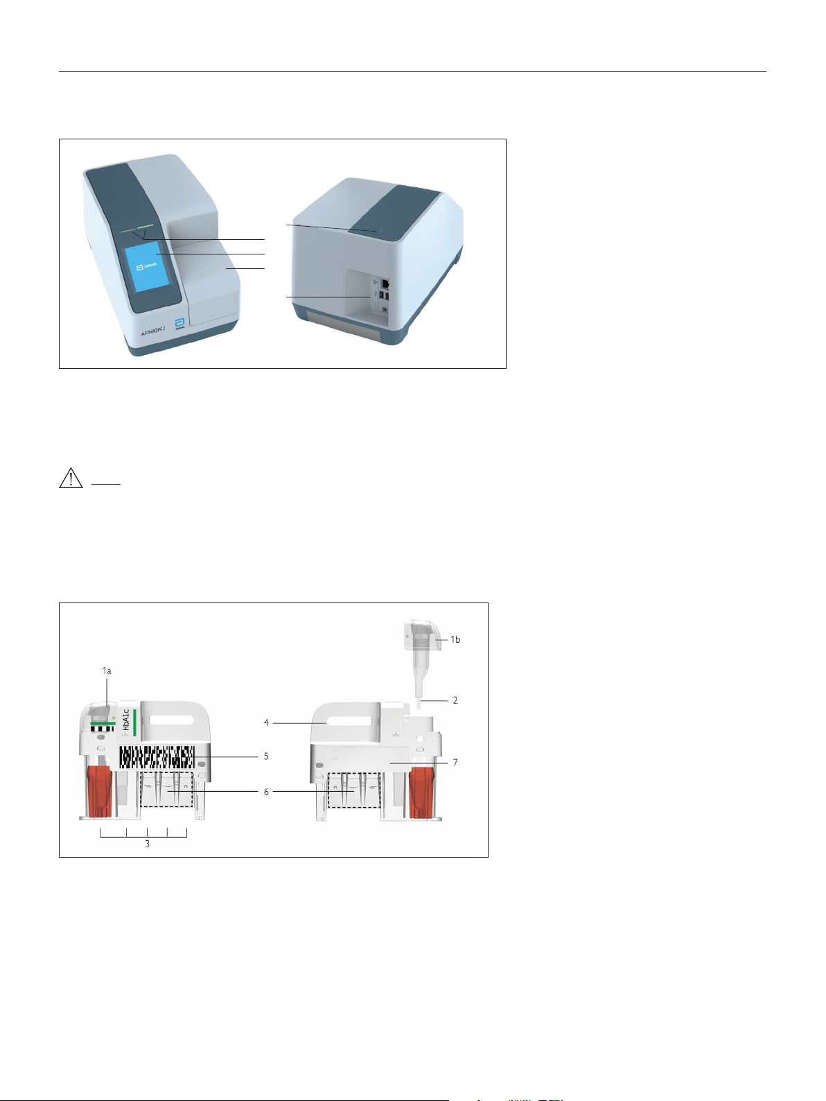
Description of the AFINION™ 2 Analyzer
Figure 1 shows the main exterior parts of the Anion 2 Analyzer.
1
2
3
4
5
Figure 1
1 ON/OFF button: Turns the power to the analyzer on and off.
2 Red and green LEDs: Light emitting diodes (LEDs) that indicates whether the analyzer is busy or not.
3 Touch screen: Allows you to communicate with the analyzer through touch buttons and messages.
4 The lid: Covers and protects the cartridge chamber.
5 Connectors: For connecting to mains power supply. Options for printer, barcode reader and/or LIS/HIS/EMR.
Do not open the lid manually.
Description of the Anion™ Test Cartridge
The Anion Test Cartridge is unique for each analyte to be measured, as the reagent composition, reagent volumes and the integrated devices are test specic.
The test cartridge label has a colour unique for the test. The test cartridges are separately packed in foil pouches to protect the reagents and plastic devices from
light, dirt and humidity. A single test cartridge contains all necessary reagents for one test and is ready to use. An integrated sampling device is used for collection
of the patient sample or control. The test cartridge cannot be reused. Figure 2 illustrates an Anion Test Cartridge with its functional parts:
Left side Right side
Figure 2
1 Sampling device: For collection of patient sample or control (1a - closed position, 1b - lifted position).
2 Capillary: Capillary to be lled with sample material.
3 Reaction wells: Contain all necessary reagents for one test.
4 Handle: For correct nger grip.
5 Barcode label: Contains assay and lot-specic information for the analyzer.
6 Optical reading area: Area for transmission measurement.
7 ID area: Space for written or labelled sample identication.
8 | US
AFINION™ 2 User Manual
Page 9

Analyzer System Description
How the AFINION™ 2 System works
The Anion 2 System uses different chemical and mechanical assay methods combined with advanced, computerized processing and measuring technology.
A test cartridge with patient sample or control is placed in the cartridge chamber of the analyzer. By manually closing the lid, the test cartridge is transported
into the analysis compartment of the analyzer. Test and lot-specic information is obtained from the barcode label (Figure 2). When the test cartridge enters the
analyzer, the integrated camera reads the barcode which then initiates the processing of the test cartridge. The sample and reagents are automatically transferred
between the wells. An internal camera monitors the entire process. Light-emitting diodes (LEDs) illuminate the reaction area, which can be either a coloured
membrane or a reaction well. The camera detects the reected or transmitted light, which is converted to a test result and displayed on the touch screen. When the
user accepts the result, the lid covering the cartridge chamber opens automatically and the used test cartridge can be removed and discarded. The analyzer is then
ready for the next run.
Internal process control
The analyzer self-test
A self-test is performed during start-up of the analyzer to ensure that the instrument is operating according to established specications. The self-test validates:
• Hardware and software integrity
• Test cartridge transport system
• Liquid transport system
• Camera vision system
If the self-test fails at any point, the red LED will start ashing and an information code will be displayed on the touch screen
(see “Information codes and troubleshooting”, page 26-28).
When the analyzer is powered on for a longer period, it will automatically restart once a day to ensure that a self-test is done regularly. This procedure does not
interrupt any analysis of the test cartridge.
The fail-safe mechanisms
Fail-safe mechanisms are included to secure safe processing. The integrated camera inspects the test cartridges initially before the process starts and during the
assay. If defects are detected (e.g. broken capillary, the cartridge is used past its expiry date), the test cartridge is rejected and an information code is displayed.
During processing vital functions and components (e.g. pumps, heater) are supervised. When problems are detected by the built-in safety mechanism, the process
will be aborted and an information code will be displayed.
External process control
Patient ID
The Anion 2 patient ID functionality will, if congured, allow up to four patient ID elds to be entered. The patient ID will be stored with each patient test result in
the result records.
Operator ID
The Anion 2 operator functionality will, if congured, require the operators to login before testing. The functionality may also prevent unauthorized operators to
login, perform tests and conguration. The operator ID will be stored with each test result in the result records.
Quality Control lockout
The Anion 2 QC lockout function allows you to congure the instrument to automatically enforce your local required frequency of control testing. If the required control
test has not been performed or the control result is outside the acceptable range, the instrument will disable patient testing for this assay. For manufacturer recommendations (see “Frequency of control testing” page 19).
For more information regarding these functionalities, see “Conguration” page 12–18.
Calibration
The Anion 2 Analyzer has been manufactured to deliver reliable and accurate results. During manufacturing, the analyzers are calibrated against a reference system. This procedure has been established to ensure that all analyzers operate within identical tolerance limits.
Test specic calibration data are established for each lot of test cartridges and then stored in the barcode label (Figure 2). When the test cartridge enters the
analyzer, the integrated camera reads the barcode. The calibration data for the actual lot are transferred to the instrument and used for calculating the results.
Calibration by the operator is thus not required.
AFINION™ 2 User Manual
US | 9
Page 10
Getting Started
Installing your analyzer
Place your Anion 2 Analyzer on a dry, clean, stable and horizontal surface. Make sure that the analyzer is located with sufcient surrounding airspace, at least 5
inches on each side. Placement of Anion 2 Analyzer should allow easy disconnection from the wall outlet at any time. Acclimate the analyzer to ambient operating
temperature (15-32°C, 59-89°F) before use.
The analyzer might be impaired by:
• Condensing humidity and water
• Heat and large temperature variations
• Direct sunlight
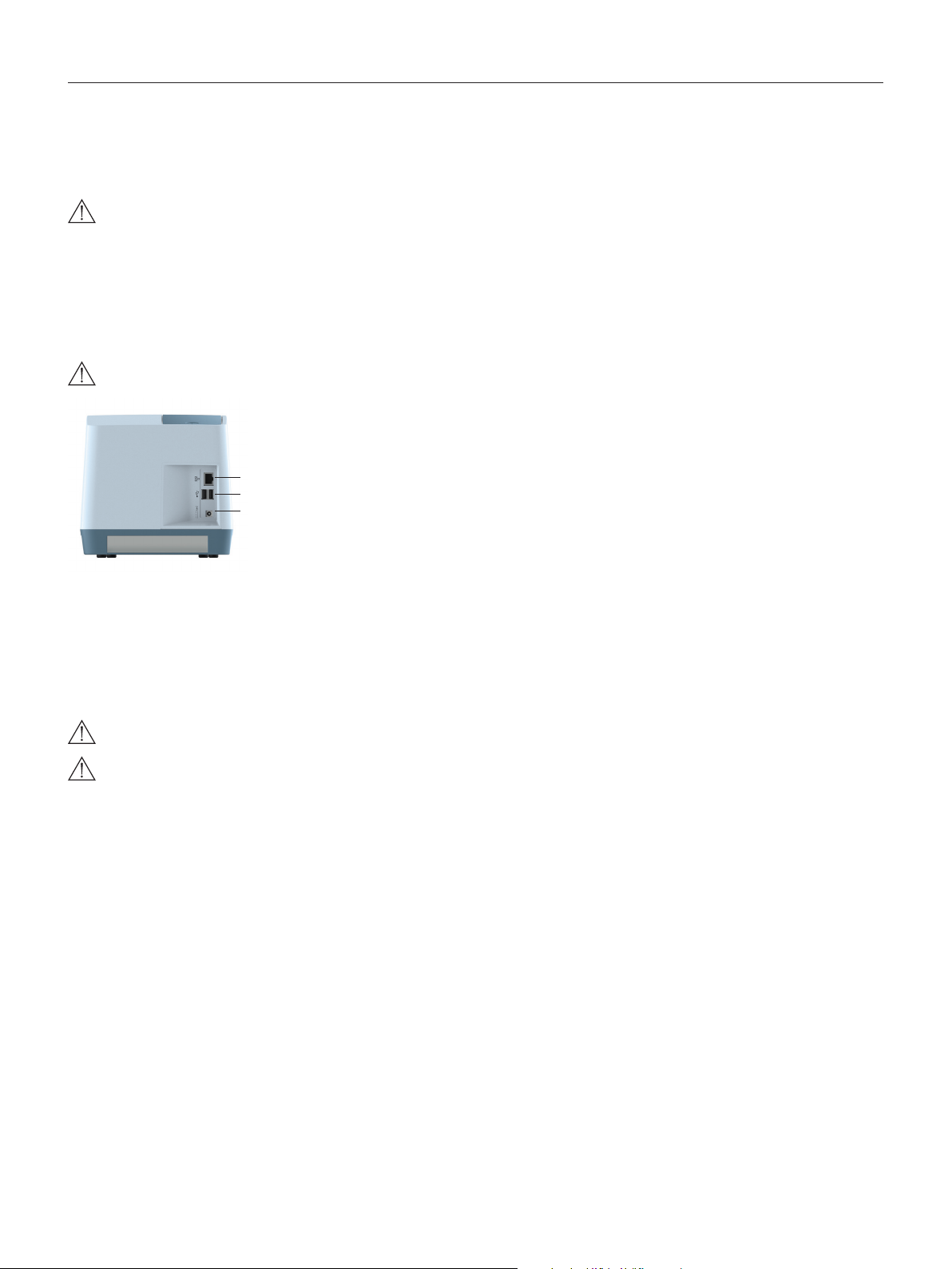
Connecting power supply
- Connect the power cable to the power supply.
- Insert the plug from the power supply into the power socket (Figure 3) in the back of the analyzer.
- Plug in the power supply to a wall outlet.
Only use the power supply and cable supplied with Anion 2 Analyzer. Any other power supplies or cables can damage the analyzer and may cause possible hazards.
Figure 3
1
1 Ethernet port for connection to LIS/HIS/EMR systems. Use shielded cable.
2
2 USB-A connectors for printer, USB ash and barcode reader.
3
3 Power input for power supply connection
• Vibrations (e.g. from centrifuges and dishwashers)
• Electromagnetic radiation
• Movement of the analyzer during processing of a test cartridge
Connecting additional equipment
Optional equipment, not provided with your Anion 2 Analyzer are:
• External barcode reader – for reading barcoded sample or operator identication.
• Printer – for optional print out of test results.
For additional information regarding barcode reader and printer specications, please contact your local Anion 2 supplier.
Connecting the equipment should be done while the analyzer is powered off.
All equipment connected to the USB and/or Ethernet ports must have double or reinforced insulation from mains to prevent the risk of electric shock.
Connectivity
Anion 2 Analyzer can reliably transfer test information to an information system. Use the Ethernet cable to interface the Anion 2 Analyzer to an information system.
Anion 2 Analyzer automatically transfers patient and control results to a connected LIS/HIS/EMR system via TCP/IP networking using the protocols POCT1-A,
HL7, ASTM 1381-85 (low level) or ASTM 1394-97 (high level), selectable by conguration. ASTM and HL7 protocols support the transfer of patient and QC
results. POCT1-A protocol supports in addition functions such as device lockout and operator list management. Operator conguration allows for protection of
connectivity settings. When operator conguration is set to operator ID with verication, the conguration of connectivity will only be available for operators at
supervisor level. For relevant information, see chapter “Operator conguration”, page 14.
When you export data that contains patient information, it is your responsibility to comply with your local regulations on protection of personal health information.
Anion 2 Analyzer POCT1-A, ASTM and HL7 communication protocols are available at www.alere.com or by contacting your local Anion 2 supplier.
10 | US
AFINION™ 2 User Manual
Page 11
GETTING STARTED
How to power ON the analyzer
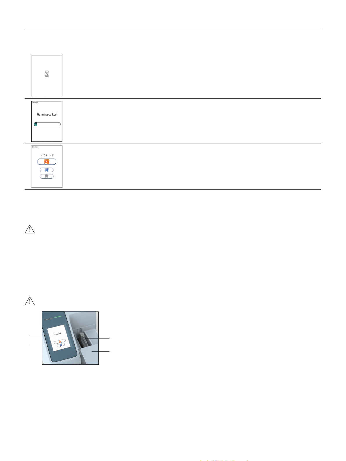
1
Power on the analyzer by pressing the ON/OFF button (Figure1). An automatic start-up procedure will be initiated. Please wait.
Do not open the lid manually.
Getting Started
2
3
The automatic start-up procedure will be initiated shortly after the analyzer has been powered on. The red light on the top of the analyzer will
turn on, indicating that the analyzer is busy. The analyzer is ready for use when the start-up menu is displayed and the green indicator light
turns on.
Start-up menu
The analyzer’s software version (SW X.XX) will appear in the upper left corner of the Start-up menu screen. The temperature displayed in the
Start-up menu is the operating analyzer temperature. Make sure that the operating temperature is within the recommended range for your
Anion Test (see the package insert for the Anion Test).
If the analyzer fails during the start-up procedure, an information code will appear referring to a message given in the section “Information
codes and troubleshooting”, page 26-28.
How to power OFF the analyzer
Switch off the analyzer by pressing the ON/OFF button (Figure 1). The analyzer should be powered off after the end of a working day.
The analyzer can only be powered off when the cartridge chamber is empty and the lid is closed. If the ON/OFF button is pressed and the lid is open, the
message ”Close lid” will appear on the screen.
How to operate the analyzer
The Anion 2 Analyzer has two main user interfaces, the touch screen and the cartridge chamber. The analyzer is easily operated using the touch buttons that appear
on the screen. When a button is touched, its function will be activated. Text messages that appear on the screen will help guide you through the testing procedure.
The functions of the touch buttons are explained in the section “Gallery of icons”, page 32–34.
The other main operative part of the Anion 2 Analyzer is the cartridge chamber. The cartridge chamber is designed to receive the test cartridge in one orientation
only. The lid must be manually closed, but opens automatically. When a new test cartridge is placed in the chamber, manually closing the lid will initiate the analysis.
When the analysis is complete the lid will open automatically. The lid protects the cartridge chamber from dust, dirt, light and humidity during processing and when
the analyzer is not in use.
• The lid must be manually closed, but opens automatically. Do not open the lid manually.
• Use the ngertips only on the touch screen. Do not use pens or other sharp instruments.
Figure 4
1
2
Screen saver
The screen saver will turn on after 3 minutes, if the touch screen is not in use. To reactivate, touch the screen.
Light signals (the red and green LEDs)
The red diode is illuminated when the analyzer is busy. A ashing red light is seen when an information code is displayed. The green diode is illuminated when the
analyzer is ready for use. A ashing green light indicates completion of an analysis.
Sound signals
A short beep indicates completion of an analysis. Two beeps mean that an information code or message is displayed.
1 Text message
2 Touch buttons
3
3 The cartridge chamber
with a test cartridge
4
4 The lid in open position
AFINION™ 2 User Manual
US | 11
Page 12

Conguration
The AFINION™ 2 menus
Main menuStart-up menu
Patient ID conguration
menu
Language setting
Date/Time
menu
Conguration menu
Operator conguration
menu
Screen/beeper
menu
QC lockout conguration
menu
12 | US
General settings
menu
AFINION™ 2 User Manual
Page 13

Conguration
Setting the conguration
Before using your Anion 2 Analyzer you should set the conguration according to your needs. To enter the Conguration menu, do the following:
1
Start-up menu
Touch to enter Main menu.
2
3
Main menu
Touch to enter Conguration menu.
Conguration menu
Select an item for conguration (see following pages).
Patient ID conguration
Patient ID enable/disable
The patient identication (ID) function can be enabled or disabled. The patient ID function is enabled as a default setting by the manufacturer. When the patient
ID function is enabled, the patient ID must be entered for each test cartridge to be analyzed. If the patient ID function is disabled, a run number will automatically
replace the patient ID and be displayed in the upper left corner of the screen. This numbering is reset each day at midnight.
Touch
in the conguration menu to enter the patient ID on/off option.
Select to disable the patient ID function.
Select to enable the patient ID function.
Touch to accept and return to the Conguration menu.
AFINION™ 2 User Manual
US | 13
Page 14

Conguration
Operator conguration
The operator ID function is disabled as a default setting by the manufacturer.
Touch
Operator ID enable/disable
Touch
Operator login expiration
Touch
in the Conguration menu to enter the Operator conguration menu.
in Operator conguration menu to enable/disable operator ID.
Select to disable the operator ID function.
Select to enable operator ID. Any operator ID is accepted.
Select to enable operator ID with verication.
· To enable this function at least one supervisor is required to be present in the operator list.
· When operator ID with verication is enabled, analyzer conguration will only be available to the supervisors.
· To log in, the operator ID entered is required to be present in the operator list. See “Operator list management”, page 14.
Touch to accept and return to the Conguration menu.
in the Operator conguration menu to set automatic logout of the operator.
Enter the number of minutes before automatic logout of operator.
The operator will automatically be logged out after the congured number of minutes after ended test.
Touch to conrm and return to previous view.
Operator list management
Touch
1
2
3
in Operator conguration menu to enter operator list.
Touch to add new operator.
Touch desired operator ID and touch to delete or to edit the highlighted operator.
Copy operator list
It is possible to copy an existing operator lists between analyzers using a USB ash drive. Insert USB ash in the analyzer USB port.
Touch to export operator list from instrument to USB ash. Move USB to the new analyzer and touch
existing operator list on the analyzer will be deleted.
Enter new/edit operator ID
Enter new/edit operator ID and touch to enter. Both letters and numbers can be entered (maximum 16 characters).
If a barcode reader is connected to the analyzer, a barcoded operator ID can be entered.
Congure the operator level
Select USER to congure user access.
Select SUPERVISOR to congure supervisor access.
Congure tests accessible:
Select the test accessible for this operator.
Touch to return and edit the operator ID.
Touch to accept and store new operator in the operator list. The operator list can store 1000 operator IDs.
Supervisors will be marked with * in the operator list. When analyzer is congured to Operator ID with verication, conguration of the
analyzer will only be available to the supervisors.
to import operator list. Any
14 | US
AFINION™ 2 User Manual
Page 15

Conguration
Choosing language
Touch in the Conguration menu to enter the language setting. The default setting by manufacturer is English. Other languages are available.
1
Touch the arrow in the window to view other options. Scroll down until you nd the preferred language.
Touch to accept and return to the Conguration menu.
Adjusting screen/beeper settings
Touch in the Conguration menu to enter the Screen/beeper menu.
Touch to enter the Screen alignment setting.
Touch to enter the Beeper volume setting.
A + sign is shown. Use a blunt pencil and tap the center of the +. Repeat tapping the center of the + each time it is shown. When the
process is nished, the previous screen will return.
Adjust the beeper volume by touching or
Touch to conrm and return to the previous view.
Setting date and time
The correct date and time should always be set because the date and time for the analyses are stored and displayed in the patient and control records. The
date format is YYYY:MM:DD, where YYYY is the year, MM is the month (01 to 12), and DD is the day (01 to 31). The time format is hh:mm, where hh is the hour
from 00 to 23 and mm is minutes from 00 to 59.
Touch in the Conguration menu to enter Date/time menu.
1
2
Touch to enter Date setting.
Touch to enter Time setting.
Enter today’s date or time.
Touch to conrm and return to the previous view.
AFINION™ 2 User Manual
US | 15
Page 16

Conguration
QC lockout conguration
Touch in the Conguration menu to enter the QC lockout conguration menu.
Touch to congure QC lockout for the assay selected.
Touch to congure QC lockout interval.
Touch to view/add/delete stored control lots in the control lot database.
1
HbA1c
ACR
2
3
4
Select assay for QC lockout conguration
Touch the arrow in the window to open the drop down menu.
Touch the assay to select.
QC lockout
Select to disable the QC lockout function. No QC runs will be required for this assay.
Select to enable the QC lockout function. It is required to run ONE passed control,
control level C I OR C II, to reset the QC lockout interval.
Select to enable the QC lockout function. It is required to run TWO passed controls,
both control level C I AND C II, to reset the QC lockout interval.
Touch
QC lockout interval
Select
Select to congure QC lockout interval by hours.
Touch
Touch
Control lot database
To add a control to the control lot database the Anion Control Data is required.
The Anion Control Data is a numeric data string which contains all lot specic data:
• Anion Control lot number
• Control type (assay)
• Control level (C I or C II)
to conrm and return to the previous view.
to congure QC lockout interval by number of runs.
to enter/edit number of runs/hours to QC lockout.
displays the number of runs/hours congured in the QC lockout interval.
to conrm and return to the previous view.
• Control expiry date
• Acceptable control range
• CRC (check sum to validate the previous data)
16 | US
The Anion Control Data and its accompanying barcode is found in the Anion Control Package Insert. If the Anion Control Data is not
available, contact your local supplier.
Touch and either manually enter the Control Data or if a barcode reader is connected to the analyzer (recommended), scan the
barcode.
The Anion Control Data may also be entered before, during or after a control run. The control lot will automatically be stored in the
database. See page 25.
Select lot number and touch to delete a control from the list.
When a control lot has reached its expiry date, the control will automatically be deleted from the instrument control database. The control
lot database can store 100 control lots.
AFINION™ 2 User Manual
Page 17

General settings
Touch
in the Conguration menu to enter the General settings menu.
Conguration
Touch
Touch
Touch
to erase all content and congurations.
to enter Instrument network settings.
to enter Connectivity settings.
Erase all contents and congurations
Touch
in General settings menu to erase all contents and congurations.
Touch
Touch
to erase all content and congurations.
to cancel and return to General settings menu.
Analyzer network settings
See Table 1 for description of the available analyzer network settings.
Touch
to enter Instrument network settings view.
Touch
to congure the network.
Enter the IP Address. Touch
Enter the Gateway. Touch
Enter the Network mask. Touch
Enter the Hostname. Touch to conrm and return to Instrument network settings view.
Touch
Table 1 Description of the available analyzer network settings
Consult your network administrator and LIS/HIS/EMR administrator for required network settings.
DHCP DHCP is turned on/off by selecting “DHCP”.
IP address Insert xed IP address [0-255/0-255/0-255/1-254]
Gateway Insert Gateway [0-255/0-255/0-255/1-254]
Network Mask Insert Network mask [0-255/0-255/0-255/0-255]
Host name Insert Host name. Valid characters are [A-Z], [0-9], [-]. The length can be from 1-16 characters
to accept and return to the General settings menu.
When using DHCP the instrument’s IP address will be assigned by the DHCP Server.
No other network settings are necessary.
NB! If DHCP is activated, only the hostname setting can be edited.
to conrm and continue to Gateway.
to conrm and continue to Network mask.
to conrm and return to Hostname.
AFINION™ 2 User Manual
US | 17
Page 18

Conguration
Connectivity settings
See Table 2 for description of the available Connectivity settings.
Touch
Touch to enter page 2 of the conguration or to return to the General settings menu
Touch to enter Server IP and Port number, Receiving application (available for ASTM HL, ASTM LL and HL7 only) and Receiving facility (available
for HL7 only).
Enter the server IP address: Press
Enter the server port number setting: Touch
Enter the Receiving application setting: Press
Use the button to select Patient ID as (available for HL7 only):
HIS Patient ID
Visit Number
in General settings to enter Connectivity settings
Select appropriate communication protocol
ASTM HL
ASTM LL
HL7
POCT1-A
Communication protocol is disabled as default.
Select which results to be transferred to LIS/HIS/EMR by selecting the appropriate button
Patient results only
Patient and control results
Select “New results only” and previous obtained results will not be transferred to the LIS/HIS/EMR
to continue to the Port number setting.
to continue to the Receiving application setting or to close the text input.
to continue to the Receiving facility setting or to close the text input.
Touch
Table 2 Connectivity settings
Consult your network administrator and LIS/HIS/EMR administrator for required connectivity settings.
Protocol ASTM HL ASTM High Level: The communication protocol is based on ASTM E 1394 - 97
Results Patient results only Only patient results will be transferred to the LIS/HIS/EMR
Server IP Insert the IP address of the receiving system [0-255.0-255.0-255.1-254]
Port [0-65535] (0 = not set)
Receiving
Application
Receiving Facility (HL7 only)
Patient ID As HIS Patient ID (HL7 only)
For further information about the connectivity settings, see the Anion 2 data sheets for POCT1-A, ASTM and HL7 which can be obtained at www.Alere.com or
through your local Anion supplier.
to return to the General Settings menu
ASTM LL ASTM Low Level: The communication protocol is based on ASTM E 1381 - 95
HL7 HL7: The communication protocol is based on HL7 version 2.4
POCT1-A POCT1-A: The communication protocol is based on CLSI: POCT01-A2 Point-of-Care Connectivity; Approved
Disabled Data connectivity is disabled
Patient and quality
control
Visit Number (HL7 only)
Standard – Second Edition
Both patient and QC results will be transferred to the LIS/HIS/EMR
(ASTM HL, ASTM LL and HL7 only)
Receiving application name (0 – 30 characters)
Receiving facility name (0-30 characters)
18 | US
AFINION™ 2 User Manual
Page 19

Quality Control
Why quality control testing?
Quality control testing should be done to conrm that your Anion 2 System is working properly and provides reliable results. Accurate results for patient samples
can only be assured when controls are used routinely and the values are within the acceptable ranges.
Choosing control material
Controls supplied by Alere Technologies AS are recommended for use with the Anion 2 System. These control kits contain control materials with established
acceptable ranges for the Anion 2 System.
If you decide to use controls from another supplier, you will need to determine their precision and to establish acceptable control ranges for the Anion 2 System.
Handling and testing controls
Consult the package insert that comes with each control kit for detailed instructions on handling and storage of the control material.
To run a control, follow the procedure in the section “Testing procedures”, page 20-25.
The measured value should be within the acceptable range stated on the control vial label or in the control package insert. If the control results are within the
acceptable ranges, patient samples may be tested and results reported.
If the result obtained for a control is out of range, make sure that:
- The control vial has not passed its expiration date.
- The control vial has not passed the declared stability for opened vials.
- The control vial and Anion Test Cartridges have been stored according to recommendations.
- There is no evidence of bacterial or fungal contamination of the control vial.
Correct any procedural error and retest the control material. If no procedural errors are detected, it is recommended to examine the laboratory’s quality control
record to investigate the frequency of control failures. Ensure that there is no trend in out-of-range quality control results. Retest the control material using a new
control vial.
Patient results must be declared invalid when controls do not perform as expected. Contact your Technical service representative (1.866.216.9505) for
advice before analyzing patient samples.
Frequency of control testing
It is recommended that controls are analyzed:
• When starting up an Anion 2 Analyzer for the rst time.
• With each new shipment of Anion Test Kits.
• With each new lot of Anion Test Kits.
• Anytime an unexpected patient test result is obtained.
• When training new personnel in the correct use of the Anion 2 System.
• If national or local regulations require more frequent testing of control materials, perform quality control in compliance with the regulations for your facility.
• Users with a low frequency of testing should analyze controls at least every 30 days.
The controls should always be analyzed if an unexpected test result is obtained (see the Anion Test Package Insert, section Test result reporting). If
local, state and/or federal regulations require more frequent testing of control materials, then quality control should be performed in compliance with these
regulations. Each laboratory site can benet from establishing a quality control plan. The laboratory director should determine whether additional testing is
appropriate for their laboratory.
AFINION™ 2 User Manual
US | 19
Page 20

Testing Procedures
Operating precautions
When operating the analyzer:
• Use your ngertip to operate the touch screen. Do not use pens or other objects that may scratch or damage the screen. Exception: If the screen
alignment function is required, you will need to use a blunt pencil.
• The lid opens automatically, but must be closed manually. Do not try to open the lid manually.
• The lid protects the cartridge chamber from dust, dirt, light and humidity. Empty the cartridge chamber and keep the lid closed when the analyzer
is not in use.
• If an information code appears on the screen during the analysis, please consult the “Information codes and troubleshooting” section, page 26-28.
• Do not move the analyzer when a test cartridge is being processed.
When handling the test cartridge:
• Do not use test cartridges after the expiration date, or if the test cartridges are not stored in accordance with the recommendations.
• Do not touch the test cartridge optical reading area. Hold the test cartridge by the handle. (Figure 2).
• Do not use the test cartridge if the foil pouch, the desiccant bag or the test cartridge itself is damaged.
• The test cartridges must reach recommended operating temperature before use.
• Do not open the foil pouch until just before use. Once opened, the test cartridge has limited stability.
• Handle and dispose the test cartridges and sample collection equipment as potential biohazardous materials. Use gloves.
• Do not reuse any part of the test cartridge.
Consult the package insert that comes with each Anion Test Kit for assay specic information.
Preparing for an AFINION™ 2 analysis
- Allow the Anion Test Cartridges to reach the recommended operating temperature before use.
- Power on your Anion 2 Analyzer so it is ready for the day’s rst analysis.
- Enter the operator ID (optional). See procedure on page 22.
- The patient ID, control ID or Anion Control Data can be entered before or during processing of the test cartridge in the analyzer.
See procedures on page 22-25.
Consult the package insert that comes with each Anion Test Kit for assay specic information.
Tear strip
1
Open the foil pouch. Grip the handle and remove
the test cartridge from the pouch.
Discard the desiccant bag and foil pouch in
suitable waste containers.
When rst opened, the test cartridge has limited
stability.
If a barcode reader is connected to the analyzer, a barcoded patient ID, control ID or Anion Control Data can be entered.
2 3
Inspect the cartridge. Do not use the test
cartridgeif it is damaged or if loose desiccant
particles are found on the test cartridge.
Use the handle to avoid
touching the optical reading area.
Mark the test cartridge with the patient
or control ID. Use the ID area on the test
cartridge. An ID label can also be used.
Do not write on the barcode label or allow
it to become wet, dirty or scratched.
If an ID label is used, this must t into the
ID area.
20 | US
AFINION™ 2 User Manual
Page 21

Testing Procedures
Collecting a sample
• The patient sample material and control material to be used is specic for each Anion Test.
• The length of the capillary in the sampling device, and thereby the sample volume, might also vary for the different Anion Tests.
• The time from lling the capillary until analysing the test cartridge must be as short as possible.
• Do not use the test cartridge if dropped on the bench or oor after the sample has been collected.
Consult the package insert that comes with each Anion Test Kit for assay specic information.
Examples:
1 2 3
Remove the sampling device from the test
cartridge.
Use the handle to keep the test cartridge steady
against the table and pull the sampling device
straight up.
Fill the capillary; hold the sampling device almost
horizontally and bring the tip of the capillary in
surface contact with the sample. Make sure that
the capillary lls completely. It is not possible to
overll.
Do not wipe off the capillary.
Avoid air bubbles and excess sample on the
outside of the capillary.
Immediately and carefully replace the
sampling device into the test cartridge.
The time from lling the capillary until
analysing the test cartridge must be as
short as possible.
Analysing a patient/control sample
1 2 3
Touch to enter the patient sample mode.
Touch to enter the control mode.
The lid opens automatically.
Insert the test cartridge with the barcode label
facing left.
Be sure that the test cartridge is correctly placed in
the cartridge chamber.
A “C” in the upper left corner indicates that the
analyzer is in the control mode.
4 5 6
Touch and enter the patient ID.
Touch to conrm.
Touch and enter the control ID or Anion
Control Data.
Touch to conrm.
Entering the patient ID, control ID or Anion Control
Data will not interrupt the processing.
Record the result, then touch to accept.
If a printer is connected, touch to print
the result.
The lid opens automatically.
The result will be saved in the result records.
Close the lid manually.The analyzer will start
processing the test cartridge.
The processing time depends on the test
in use.
Remove the used test cartridge from the
cartridge chamber and discard it in a
suitable waste container.
Insert a new test cartridge or close the lid
manually.
Keep the lid closed to protect the cartridge
chamber when the analyzer is not in use.
Consult the package insert that comes with each Anion Test Kit for assay specic information.
AFINION™ 2 User Manual
US | 21
Page 22

Testing Procedures
Using the operator ID function
Entering operator ID
If enabled, the operator’s identication (ID) is required before processing an Anion Test Cartridge (see “Operator conguration”, page 14).
Both letters and numbers can be entered (maximum 16 characters). The operator ID will be displayed with the result and stored along with the other specic data
for this run (see “Patient and control results records”, page 25).
If congured to “enabled with verication” the operator ID entered is required to be present in the operator ID list (see “Operator conguration”, page 14).
Enter the operator ID by numbers and/or touch to enter letters. If a barcode reader is connected to the analyzer, a bar coded
operator ID can be entered.
Touch to conrm and return to previous view.
The operator will be automatically logged out according to the conguration (see “Operator conguration” page 14).
The operator may also manually logout by using the operator logout button displayed in the Start-up menu.
Using the patient ID function
The patient ID function is enabled as a default setting. As long as this function is enabled, the patient ID must be entered for each patient sample to be analyzed. The
patient ID function can be disabled (see “Patient ID conguration”, page 13).
Entering patient ID
It is recommended to enter the patient ID during processing of the test cartridge in the analyzer. Entering the patient ID will not interrupt the processing. It is also
possible to enter the patient ID before the processing.
1
2
3
The P-ID 1 will be stored in the memory and displayed along with the other specic data for this run (see “Patient ID conguration” page 13). Patient ID 2-4 will not
be displayed in the result records but will be stored in the memory and appear on printouts and data transferred to data management systems.
Touch to enter the patient ID option.
It is possible to enter up to four patient ID entries for each patient, P-ID 1 to 4. When enabled, P-ID 1 is required to be entered. Scrolling
between the patient IDs is done with the and .
Enter patient ID by numbers and/or touch to enter letters (maximum 16 characters).
If a barcode reader is connected to the analyzer, a barcoded patient ID can be entered.
Touch to conrm and return to previous view.
The entered P-ID 1 will appear on the screen.
The patient ID touch button will remain in the view and it is possible to make corrections.
22 | US
AFINION™ 2 User Manual
Page 23

Testing Procedures
Using the control ID function
In quality control testing, a suitable control ID must always be entered. The lot number of the control material is recommended as a suitable control ID. The control
ID function cannot be disabled.
Entering Control ID
It is recommended to enter the control ID during processing of the test cartridge in the analyzer. Entering the control ID will not interrupt the processing. It is also
possible to enter the control ID before processing. Both letters and numbers can be entered (maximum 16 characters). The control ID will be stored in the memory
and displayed along with the other specic data for this run.
To enter the control ID during processing, do the following:
1
2
3
Touch to enter the control ID option.
Enter control ID by numbers and/or touch to enter letters.
Touch to conrm and return to the previous view.
The entered control ID will appear on the screen.
The control ID touch button will remain in the view and make corrections possible.
Using the QC lockout function
When the QC lockout function is enabled for one or more assays, approved control testing is required within the congured interval. If the interval expires, patient
testing for the assay will be locked. A passed control run must be performed according to conguration to reset the interval or to unlock the assay for patient testing.
A failed control run will disable patient testing (see “QC lockout conguration”, page 16).
QC lockout status
The status of the active QC lockouts is presented with a QC lockout status button (padlock symbol) visible in the Start-up menu. This gives the operator the status
of QC lockout before he attempts to run any tests.
The padlock symbol will only be visible if QC lockout function is enabled for one or more assay types.
The padlock symbols used are:
Enabled-unlocked
All controls are within the congured interval. It is possible to run patient tests for all assays.
Warning-unlocked
All controls are within the congured interval. When one or more of the assays has 10 % or less of the congured interval remaining the
warning icon will be displayed. It is possible to run patient tests for all assays.
Expired-locked
One or more controls have expired according to the congured interval. Patient testing on the expired assay has been locked.
AFINION™ 2 User Manual
US | 23
Page 24

Testing Procedures
Touch the QC lockout status button (padlock symbol) in the Start-up menu to enter the QC lockout status view.
Status
The information is displayed as a list.
Only the assays with QC lockout activated are displayed in this window.
Red text indicates expired assays and orange text indicates assays within warning period.
Control level
How to reset QC lockout interval and/or unlock expired assays.
If no control level is specied, it is required to run ONE passed control, control level C I OR C II, to reset the QC lockout interval and unlock
the assay for patient testing.
E.g.
HbA1c: #0
If the control level is specied it is required to run TWO passed controls, both control level C I AND C II, to reset the QC lockout interval
and unlock the assay for patient testing.
E.g.
ACR C I: 00.00.00
ACR C II: 00.00.00
Remaining time/runs
Remaining time (dd:hh:mm) or number of runs for each assay with active QC lockout is shown. dd is the number of days, hh is the number
of hours, and mm is the number of minutes until the assay will be locked. # is number of patient tests.
Running controls with enabled QC lockout function
When running controls with the QC lockout function enabled, the Anion Control Data is required to be entered or previously stored in the instrument control lot
database. See “QC lockout conguration”, page 16.
1) The Anion Control Data is entered before, during or after the control run. If a barcode scanner is connected (recommended) the control data barcode may be
scanned. The control lot will automatically be stored in the instrument control database.
2) If the Anion Control Data is previously stored in the instrument control database, the operator will simply need to enter the 8 digit control lot number before,
during or after the control run.
If the instrument is congured to QC lockout and the control lot number is not found in the Anion Control database or the Anion Control Data entered is not valid,
the instrument will present an option to retry the input or discard the control run result. If discarded, the result will not be stored in the instrument result records.
Passed (result within the acceptable control range)
The result of the control is checked against the acceptable ranges for the corresponding lot number.
If the result is within the limits, a pass symbol is displayed on the screen and the QC lockout interval is reset according to the QC lockout conguration.
If QC lockout is congured to require two control levels (C I and C II), both levels must pass to reset the
lockout interval. Only the interval for the control level used in the test is reset.
Failed (result above or below the acceptable control range)
When a control result is not within the acceptable ranges specied for the control lot, a failed symbol is shown on the screen. The result
is stored in the instrument and is sent to the data management system if connected. The QC lockout interval will not be reset.
The arrow symbol will specify whether the result is above or below the acceptable ranges.
See “Handling and testing controls”, page 19.
24 | US
AFINION™ 2 User Manual
Page 25

Testing Procedures
Patient and control results records
The patient and control results are stored in the memory of the Anion 2 Analyzer. The last 500 patient results and the last 500 control results are saved in separate
records. When exceeding the capacity of 500 results, the oldest result will be deleted. The following parameters are listed for each run: Date and time, run number,
patient ID/control ID, operator ID, lot number of test cartridge and the test result.
View, print and export patient and control results
1
Main menu
Touch to enter patient results.
Touch to enter control results.
2
Result records may be exported if an USB ash (FAT 32 formatted) is inserted to the Anion 2 USB port.
Touch to export the results. The results will be stored on the USB in a .txt le for each assay tested on the Anion 2 Analyzer. These
les may be opened in e.g. Microsoft Excel for further processing.
When you export data that contains patient information, it is your responsibility to comply with your local regulations on protection
of personal health information.
The last patient result or control is displayed
To view more results touch
If a printer is connected, touch
or
to print the result.
AFINION™ 2 User Manual
US | 25
Page 26

Information Codes and Troubleshooting
When an information code appears
Information codes that might appear during use of the Anion 2 Analyzer refer to specic information or error messages. The code numbers, the possible causes and
actions to take are listed below.
If the analyzer detects a problem during processing of a test cartridge, the test will automatically be aborted and the test cartridge will be safely moved to the
cartridge chamber. Proceed as follows:
1
2
3
Do not reuse a test cartridge that has been rejected by the analyzer. Collect a new sample and repeat the test with a new test cartridge.
Record the code number (#) and touch to accept.
The lid opens automatically.
Remove the test cartridge.
If the test cartridge is not ejected, restart the analyzer.
Do not reuse the test cartridge.
Look up the possible cause from the table below, and take actions to solve the problem.
If the problem persists, contact your local Anion supplier (see “Service information” page 28).
Information codes caused by test-specic limitations
[#] Cause Action to take
103 Hemoglobin too low Consult the Anion HbA1c Package Insert.
104 Hemoglobin too high Consult the Anion HbA1c Package Insert.
105 HbA1c too low Consult the Anion HbA1c Package Insert.
106 HbA1c too high Consult the Anion HbA1c Package Insert.
107 Creatine too high Consult the Anion ACR Package Insert.
108 Blood in urine Consult the Anion ACR Package Insert.
26 | US
AFINION™ 2 User Manual
Page 27

Information Codes and Troubleshooting
Information codes caused by sample or test cartridge
[#] Cause Action to take
201 Insufcient sample volume:
- Empty capillary
- Air bubble in capillary
- Capillary incompletely lled
202 Excess sample on the sampling
device exterior
203 Wrong sample material Repeat the test with a new sample and test cartridge. Ensure that proper sample material is used (see package insert
204 Coagulated sample Repeat the test with a new sample and test cartridge.
Hemolysed blood sample or
poor sample quality
Test cartridge or analyzer failure Repeat the test with a new sample and test cartridge.
205 Capillary cracked or damaged Repeat the test with a new sample and test cartridge.
206 Barcode label not readable
(dirty or damaged)
207 - No sampling device inserted Repeat the test with a new sample and test cartridge. Ensure that the correct sampling device is in place and that the
- Sampling device belongs to
another Anion Test
- Label on sampling device not
readable (dirty or damaged)
208 Test cartridge previously used Repeat the test with a new sample and test cartridge.
209 Test cartridge has passed
expiration date
The date in the analyzer is
incorrectly set
210 Test cartridge temperature
too low
211 Test cartridge temperature
too high
212 Software upgrade is required
to run this test.
213
Test cartridge or analyzer failure Repeat the test with a new sample and test cartridge. If the problem persists, restart the analyzer and run controls.
214
215 Test cartridge or analyzer failure Repeat the test with a new sample and test cartridge. If the problem persists, restart the analyzer and run controls.
Hemolysed blood sample or
poor sample quality
(Anion HbA1c)
217 Hemolysed blood sample or
poor sample quality
(Anion HbA1c)
218 Condensation detected on
cartridge
Repeat the test with a new sample and test cartridge.
Ensure that the capillary is completely lled with no air bubbles (see package insert for the Anion Test in use).
Repeat the test with a new sample and test cartridge. Ensure that only the tip of the capillary is in contact with the
sample (see package insert for the Anion Test in use).
for the Anion Test in use, section “Specimen collection and storage”).
The time from lling the capillary until analyzing the test cartridge should be as short as possible.
Consult the Anion Package Insert.
Repeat the test with a new sample and test cartridge.
If the problem persists, restart the analyzer and run controls.
Inspect the sampling device before use and handle with care.
Repeat the test with a new sample and test cartridge.
If the problem persists, restart the analyzer and run controls.
sampling device label is clean.
Check expiry date on the foil pouch or kit container. Repeat the test using a new sample and a new test cartridge
fromanother lot.
Check the date in the analyzer to make sure it is set correctly. Repeat the test with a new sample and test cartridge.
Repeat the test with a new sample and a new test cartridge.
Ensure that the operating temperature is within acceptable range (see package insert for the Anion Test in use).
Repeat the test with a new sample and a new test cartridge.
Ensure that the operating temperature is within acceptable range (see package insert for the Anion Test in use).
Contact your local supplier for assistance.
Consult the Anion HbA1c Package Insert. Repeat the test with a new sample and test cartridge.
Consult the Anion HbA1c Package Insert. Repeat the test with a new sample and test cartridge.
Run a new test cartridge. Ensure that the cartridge is equilibrated to room temperature before the foil pouch is opened.
Information codes and messages caused by analyzer failure
[#] Cause Action to take
27
2829Start-up procedure failed Contact your local supplier for assistance.
Self-test
error.
Analyzer
in non-
operative
mode
Analyzer failure Restart analyzer. If the problem persists, contact your local Anion 2 supplier.
301 Self-test failed Restart the analyzer.
302 Analyzer failure Restart the analyzer and run controls. Repeat the test with a new sample and test cartridge.
303 Analyzer temperature is too
high
304 Analyzer temperature is
too low
Ensure that the operating temperature is within recommended range (15-32ºC, 59-89 °F).
Wait until the analyzer has cooled down. Repeat the test with a new sample and test cartridge.
Ensure that the operating temperature is within recommended range for the Anion Test in use (see package insert).
The analyzer temperature is displayed in the Start-Up menu (see page 11). Repeat the test with a new sample and test
cartridge.
AFINION™ 2 User Manual
US | 27
Page 28

Information Codes and Troubleshooting
[#] Cause Action to take
305 Printer improperly connected
Malfunction of the printer
Touch
screen
error
Touch screen failure/ Touch
screen buttons do not
respond accurately
Other information codes
[#] Cause Action to take
401 No registered supervisors in
operator list
402 Cannot delete last
supervisor
403 This assay type is not
accessible to the operator
404 Operator ID is not found in
operator list
[#] Cause Action to take
501 The control lot has passed
expiration date
502 Anion Control Data is not
recognised and is not stored
in control lot database
503 Control verication aborted. The Anion Control Data entered was not recognised. The control test was aborted by the operator. Test result was
504 Required control test interval
has expired. Patient testing
is disabled for this assay.
Switch off the analyzer, reconnect the printer and restart the analyzer.
If the message persists, see the printer user manual.
Restart analyzer and realign screen.
At least one supervisor is required in the operator list when the analyzer is congured to operator ID veried,
(see page 14).
At least one supervisor is required in the operator list when the analyzer is congured to operator ID veried,
(see page 14).
The operator logged in does not have access to run this assay type. Please contact your supervisor.
When Operator ID with verication is enabled, operator ID entered is required to be present in the operator list,
(see page 14). Please contact your supervisor.
Check the expiration date on the control lot package insert or kit box.
Repeat the test using a sample from a new control lot.
Reenter the Anion Control Data, (see page 16).
not stored. Run new control test to reset QC lockout interval.
A passed control run must be performed according to conguration to unlock this assay for patient testing.
[#] Cause Action to take
601 Operator list or control lot
database is full
The operator list can store 1000 operators and the control lot database can store 100 control lots. Delete an operator
or control lot to enter a new item
Service information
The laboratory must notify the manufacturer of this test system of any performance, perceived or validated, that does not meet the performance
specications as outlined in the instructions.
The manufacturer provides a toll free line for technical support: 1.866.216.9505
The toll free number is available for use only in the United States of America.
Before asking for assistance, please record the following information:
• Anion 2 serial number (SN) – see label on the backside of the analyzer
• Software version number – see Start-up menu.
• Anion Test type
• Test cartridge or kit lot number – see foil pouch or kit container
• Control identication and lot number – see vial label
• Control results obtained
• Description of the problem with reference to information codes or messages
28 | US
AFINION™ 2 User Manual
Page 29

Maintenance
Cleaning and maintenance
No maintenance of the Anion 2 Analyzer is required other than cleaning the exterior and cartridge chamber.
Cleaning the exterior
Cleaning the exterior of the Anion 2 Analyzer should be performed whenever necessary. Most spills and stains can be removed with water or a mild detergent.
- Power off the analyzer. Unplug the power supply when the shut down procedure is completed.
- Clean the outside of the analyzer and the touch display with a clean, lint-free and non-abrasive cloth dampened in water or a mild detergent.
- To disinfect the exterior of the analyzer use a 1:10 solution of household bleach (i.e., 0.5% sodium hypochlorite), 2% glutaraldehyde solution or 70% alcohol
solution. The surface of the analyzer should be exposed to the disinfectant for at least 10 minutes.
- Allow the analyzer to air dry.
- Plug in the power supply and power on the analyzer.
• The analyzer must be powered off and unplugged before cleaning.
• Do not use any cleaning liquid or equipment other than those recommended above.
• Do not immerse the analyzer in water or other liquids.
Cleaning the cartridge chamber
The Cleaning Kit (
The cartridge chamber should be cleaned immediately if materials or liquids are spilled in the cartridge chamber. For regular maintenance (removal of dust
particles etc.), the cartridge chamber should be cleaned every 30 days.
- Touch to open the lid.
- Unplug the power supply.
- Wet a Cleaning Swab with 3 drops of water and gently rinse the cartridge chamber. To disinfect the surface, use a 1:10 solution of household bleach (i.e., 0.5%
sodium hypochlorite), 2% glutaraldehyde solution or 70% alcohol solution). Do not soak.
- Carefully remove spills and particles from the cartridge chamber using the moistened swab.
- To disinfect the cartridge chamber, the surface of the chamber should be exposed to the disinfectant for at least 10 minutes1.
- Wipe off any residual liquid from the cartridge chamber using a new, dry Cleaning Swab.
- Plug in the power supply, and power on the analyzer by pressing the on/off button.
- The lid will close automatically during the self-test. If it doesn’t, then close it manually and restart the analyzer.
1116048) should always be used for cleaning the cartridge chamber.
• The analyzer must be unplugged before cleaning.
• Do not use any cleaning liquid or equipment other than those recommended above.
• Do not allow liquid to drip off the Cleaning Swab into the analyzer. If liquid drips into the analyzer, optics can be destroyed.
• Do not immerse the analyzer in water or other liquids.
• Do not move or tilt the analyzer when cleaning the cartridge chamber.
Disposal of the analyzer
For correct disposal according to the Directive 2012/19/EU (WEEE), contact your local Anion 2 supplier.
Software upgrade
Consult the Anion USB Flash Drive Package Insert for software upgrade.
1
Clinical and Laboratory Standards Institute (CLSI) Guideline M29-A3: ”Protection of Laboratory Workers From Occupationally
Acquired Infections; Approved Guideline - Third Edition”. ISBN 1-56-238-567-4
AFINION™ 2 User Manual
US | 29
Page 30

Warranty
Alere Technologies AS warrants solely to the Buyer that the Anion 2 Analyzer will be free from defects in materials and workmanship, when given normal, proper
and intended usage, and will perform in accordance with Alere Technologies AS’s specications for a period of twelve months from the date of delivery.
At its expense, Alere Technologies AS agrees to repair, or at Alere Technologies AS’s option, replace with a new or reconditioned unit, any Anion 2 Analyzer which
is under warranty and not performing substantially in accordance with applicable product specications, provided that the Buyer has given Alere Technologies
AS notication of such warranty claim within the warranty period. If Alere Technologies AS is unable after reasonable efforts to repair or replace the Anion 2
Analyzer not performing substantially in accordance with applicable product specications, the Buyer’s sole remedy shall be the refund of an amount not to
exceed the actual purchase price paid by the Buyer for the Anion 2 Analyzer. All repairs will be done during normal working hours. All replaced parts shall become
Alere Technologies AS’s property. Alere Technologies AS may require the Buyer to ship the Anion 2 Analyzer to Alere Technologies AS or elsewhere at Alere
Technologies AS’s expense, for warranty service to be performed.
Notwithstanding the foregoing, Alere Technologies AS shall have no obligation to make repairs, replacements or corrections which result, in whole or in part, from
(i) an act of God or other unforeseen catastrophe, (ii) any error, omission or negligence of the Buyer, (iii) improper or unauthorized use of the Anion 2 Analyzer,
(iv)operating errors or the disregard of warnings and pre-cautions described in this Anion 2 Analyzer User Manual; (v) repairs performed to the Anion 2 Analyzer
by any person other than an authorized Alere Technologies AS service representative; (vi) use of the Anion 2 Analyzer in a manner for which it was not designed,
(vii) causes external to the Anion 2 Analyzer such as, but not limited to, power failure or electric power surges, or (viii) use of the Anion 2 Analyzer in combination
with equipment, components or software not supplied by Alere Technologies AS.
EXCEPT AS STATED IN THIS SECTION OF THE USER MANUAL, ALERE TECHNOLOGIES AS DISCLAIMS ALL WARRANTIES, WHETHER EXPRESS OR IMPLIED,
WRITTEN OR ORAL, WITH RESPECT TO THE AFINION 2 ANALYZER, INCLUDING ANY WARRANTY OF MERCHANTABILITY OR FITNESS FOR A PARTICULAR
PURPOSE. ALERE TECHNOLOGIES AS’S MAXIMUM LIABILITY ARISING OUT OF THE SALE OF THE AFINION 2 ANALYZER OR ITS USE, WHETHER BASED
UPON WARRANTY, CONTRACT, TORT OR OTHERWISE, SHALL NOT EXCEED THE ACTUAL PURCHASE PRICE PAID BY THE BUYER FOR THE AFINION 2
ANALYZER. IN NO EVENT SHALL ALERE TECHNOLOGIES AS BE LIABLE FOR SPECIAL, INCIDENTAL OR CONSEQUENTIAL DAMAGES, INCLUDING, BUT NOT
LIMITED TO, LOSS OF PROFITS, LOSS OF DATA OR LOSS OF USE DAMAGES, ARISING HEREUNDER OR FROM THE SALE OF THE AFINION 2 ANALYZER.
THIS WARRANTY MAY NOT BE TRANSFERRED BY THE BUYER.
The acknowledgement of claims shall be reported to your Technical Care Specialist at 1.866.216.9505
30 | US
AFINION™ 2 User Manual
Page 31

AFINIONTM 2 Analyzer
Analyzer
Size 200 mm W x 186 mm H x 328 mm D
Weight 3.4 kg
Display Standard LCD colour display with back light and integrated touch panel.
Resolution: 240 x 320 pixels. Visible area: 58 x 77 mm.
Camera 640 x 480 pixels
Capacity of result records 500 patient results and 500 control results
Capacity of operator list 1000 operators
Capacity of control lot database 100 control lots
SW update Via USB ash drive
Communication interface USB 2.0 High Speed, Ethernet 10/100 Mbps
Power supply
Power supply Separate AC to DC power supply. Double insulated.
Input 100-240 VAC, 50-60 Hz
Output 24 VDC ± 5% , 1.75 A, 42 W
Output connector 0.2 x 0.1 in. / 5.5 x 2.5 mm plug. Positive (+) on inner pin.
Operating conditions
Temperature 15-32°C (59-89°F)
Relative humidity 10-80%, non-condensing
Altitude Max 4000 MASL
Location Dry, clean, horizontal surface. Avoid direct sunlight.
Test cartridge temperature According to specications for the Anion Assay in use.
Storage and transport (in the original container)
Temperature -40 to 70ºC (-40 to 158°F)
Relative humidity 10-93 % at 40ºC
Technical Specications
Additional equipment
For information regarding recommended barcode reader, printer, the Anion Analyzer Cleaning Kit or USB ash drive, please call 1.866.216.9505.
AFINION™ 2 User Manual
US | 31
Page 32

Gallery of Icons
The touch buttons and their function
Touching a button on the screen will activate the function of this button. All the touch buttons that may appear during operation of the Anion 2 Analyzer are
explained below by their function.
Start-up menu
Main menu
Conguration
menu
Patient sample mode Select patient sample mode.
Control mode Select control mode.
Main menu Enter Main menu (operator ID, patient records, control records and conguration menu).
QC lockout status
QC lockout status
QC lockout status
Operator logout
button
Patient records View patient result records. View, print or export patient results.
Control records View control result records. View, print or export control results.
Conguration menu Enter conguration menu (language, patient ID on/off, date/time and screen/volume).
Patient ID
conguration menu
Operator
conguration menu
Language setting Enter language conguration.
Enabled-unlocked
All controls are within the congured interval. It is possible to run patient tests for all assays.
Warning-unlocked
All controls are within the congured interval. When one or more of the assays has 10 % or
less of the congured interval remaining the warning icon will be displayed. It is possible to
run patient tests for all assays.
Expired-locked
One or more controls have expired according to the congured interval. Patient testing on the
expired assay has been locked.
Manual operator logout button.
Congure patient ID function.
Congure operator function.
Patient ID
conguration
menu
Operator
conguration
menu
Patient and
control records
Universial
buttons
Screen/Volume menu Congure screen and volume settings (screen contrast, screen adjustment and beeper volume).
Date/Time menu Enter date/time settings (date and time).
QC lockout
conguration menu
General settings menu Enter the general settings menu.
Patient ID disabled Patient ID disabled.
Patient ID enabled Patient ID enabled and required.
Operator ID
conguration
Automatic operator
logout
Operator list Manage operator list. View, add, edit and delete operators.
Print Print result on connected printer.
Result records export Export result records to connected USB ash.
Patient ID Enter patient ID.
Control ID Enter control ID.
Enter Enter and return to previous view.
Backspace Delete previous character.
Congure QC lockout function.
Congure operator ID function.
Congure number of minutes before automatic logout of operator.
32 | US
Increase Increase contrast/volume.
AFINION™ 2 User Manual
Page 33

Menu Touch button Name Function
Decrease Decrease contrast/volume.
Scroll up View previous
Scroll down View next
Exit Exit current menu and return to previous screen view.
Accept Accept (a setting or a test result).
Abort Abort the test result or cancel operation.
Add button Add new operator or control lot.
Delete button Delete operator or control lot.
Edit button Edit QC lockout interval or operator ID.
Operator ID
conguration
Language
settings
Screen/Beeper
menu
Operator ID disabled Operator ID function is disabled.
Operator ID enabled Operator ID is required to be entered to run an Anion Test Cartridge
Operator ID enabled
with verication
Language Enter language conguration.
Screen alignment Enter screen alignment function.
Beeper volume Enter beeper volume setting.
Operator ID is required to be entered to run an Anion Test Cartridge. The operator ID is veried against the analyzer operator list.
Gallery of Icons
Date/Time menu
General settings
menu
QC lockout
conguration
menu
Operator list Operator list export Export operator list from analyzer to USB ash.
QC lockout QC lockout disabled QC lockout is disabled for this test.
QC lockout
interval
Date Enter date setting.
Time Enter time setting.
Erase Erase all content and congurations.
Instrument network
settings
Connectivity settings Enter connectivity settings
QC lockout Enable/disable QC lockout function.
QC lockout interval Congure QC warning and lockout interval.
Control lot information View, add or delete control lots stored on analyzer.
Operator list import Import operator list from USB ash to analyzer.
QC lockout enabled One passed control run of either C I or C II is required to reset QC lockout interval.
QC lockout enabled Two passed control runs, C I and C II are required to reset QC lockout interval.
Interval by number of
patient tests
Interval by number of
hours
Enter analyzer network settings
QC reminder and lockout active after a congured set of patient tests.
QC reminder and lockout active after a congured set of hours.
AFINION™ 2 User Manual
US | 33
Page 34

Gallery of Icons
Other symbols and signs
Other symbols, signs and abbreviations that may appear during operation of the Anion 2 Analyzer are explained below. These symbols or signs are only informative and can not be activated like the buttons.
Symbol Meaning Appears when?
Wait! Hour-glass icon that appears in the start-up procedure.
Information code
Operator ID Icon illustrates the operator ID.
Patient ID Icon illustrates the patient ID.
Control ID Icon illustrates the control ID.
Connected
Quality control pass Control result is within acceptable range.
Quality control failed Control result is outside acceptable range.
Result is above
acceptable range
Result is below
acceptable range
C Control The letter C will appear on the screen when the control mode is selected.
O-ID Operator ID Abbreviation used in the patient and control records.
P-ID Patient ID Abbreviation used in the patient records.
C-ID Control ID Abbreviation used in the control records.
RUN# Run number
LOT# Lot number Abbreviation used in the patient and control records for the lot number of the test cartridge.
Icon used along with a code number [#] that corresponds to code specic information messages [#]
(see “Information codes and troubleshooting”).
The instrument is connected to the LIS/HIS/EMR server. When no symbol, the instrument is not connected to the
LIS/HIS/EMR server.
The displayed control result is above acceptable range.
The displayed control result is below acceptable range.
Abbreviation used in the patient and control records for the run number of the analysis. This numbering is reset each
day at midnight.
USER User Operator with user privileges.
SUPERVISOR Supervisor Operator with supervisor privileges.
34 | US
AFINION™ 2 User Manual
Page 35

Symbols and Abbreviations
LOT
TEST CARTRIDGE
CONTROL C I
CONTROL C II
CLEANING KIT
N
CAN/CSA 22.2 No. 61010-1
The following symbols and abbreviations are used in the product labeling of the Anion 2 System.
Symbol/Abbreviation Explanation
The product conforms to all applicable EC
Directives and Regulations
IVD
In vitro diagnostic medical device
Catalogue number
Lot number
Serial number
Test cartridge
Symbol/Abbreviation Explanation
UL 61010-1
Conformity to the RoHS 2 directive
Conformity to the technical regulations for
EurAsian Conformity Mark
Conformity to the North American product
safety standards
Direct current
USB port
Control C I
Control C II
Cleaning kit
Waste electrical and electronic equipment
(WEEE)
Biological risks
Contents sufcient for ”n” number of tests
Expiration date
Storage temperature limitations
Manufacturer
Date of manufacture
Fragile, handle with care
Keep away from sunlight
Keep dry
Warnings and precautions
Consult the Anion User Instructions
Ethernet port
Double insulation
LED Light emitting diode
PC Personal computer
ID Identication
HIS Hospital information system
LIS Laboratory information system
LCD Liquid crystal display
AC Alternating current
DC Direct current
ASTM American Society for Testing and Materials
HL7 Health Level Seven
POCT1-A
EMR Electronic medical record
DHCP Dynamic host conguration protocol
IP Internet protocol
Point-of-Care Connectivity; approved
standard
AFINION™ 2 User Manual
US | 35
Page 36

Alere Technologies AS
Kjelsåsveien 161
P.O. Box 6863 Rodeløkka
NO-0504 Oslo, Norway
www.alere.com
ISO 13485 certied company
© 2018 Abbott.All rights reserved.All trademarks referenced are trademarks
of either the Abbott group of companies or their respective owners.
1116752 Rev. A 2018/09
 Loading...