

Page 1
LifeCare®
and
HomeCare®
MODEL
INFUSION
For
use
with:
LifeCare
LifeCare
LifeCare
HomeCare
For
country
04,13,15,18,22,27,
29,
36,
Model
Model
Micro
42, 46,
4
4P
Model 4H List 22100,
codes:
54,
88
4
SERIES
PUMPS
List
1814,1914,1915
List 2505,
List
1815,1916,1917
2506
24000
Technical
Service
Manual
Abbott
North
USA
Laboratories
Chicago,
II,
60064
430-01858-003
(Rev.
5/95)
Page 2
.'•'3
-..;tv
d'-.
'""
^ttJfc
/.. 5t;.i"
a^xy...
ttfjbpfc-.LTU.
>riJ
:lo
L ?:?t;t7-j::,
©Copyright 1995
This
document
retains
all
document
others without
andthe
the
exclusive
acceptsitin
the
ho:-
^OLCEST
subject
matter
rights^qtatesemination,
confidence,
written
consent
of Abbott Laboratories.
'"J
:-7"l
•
Abbott
disclosed
reproduction,
and^agtises
Laboratories
herein
are
proprietary
manufacture
nottoduplicateitin
information.
andsale. Any
wholeorin
All
Rights^served
Abbott
Laboratories
party
part
nor
discloseitto
using
this
430-01858-003(Rev. 5/95)
9Lfe.T
bSJt;..
LifeCare
and
HomeCare Model 4 Series
Page 3
Part
Number
Change
Description
History
of
Change
Remove
Destroy
and
Pages
Insert
Change
Pages
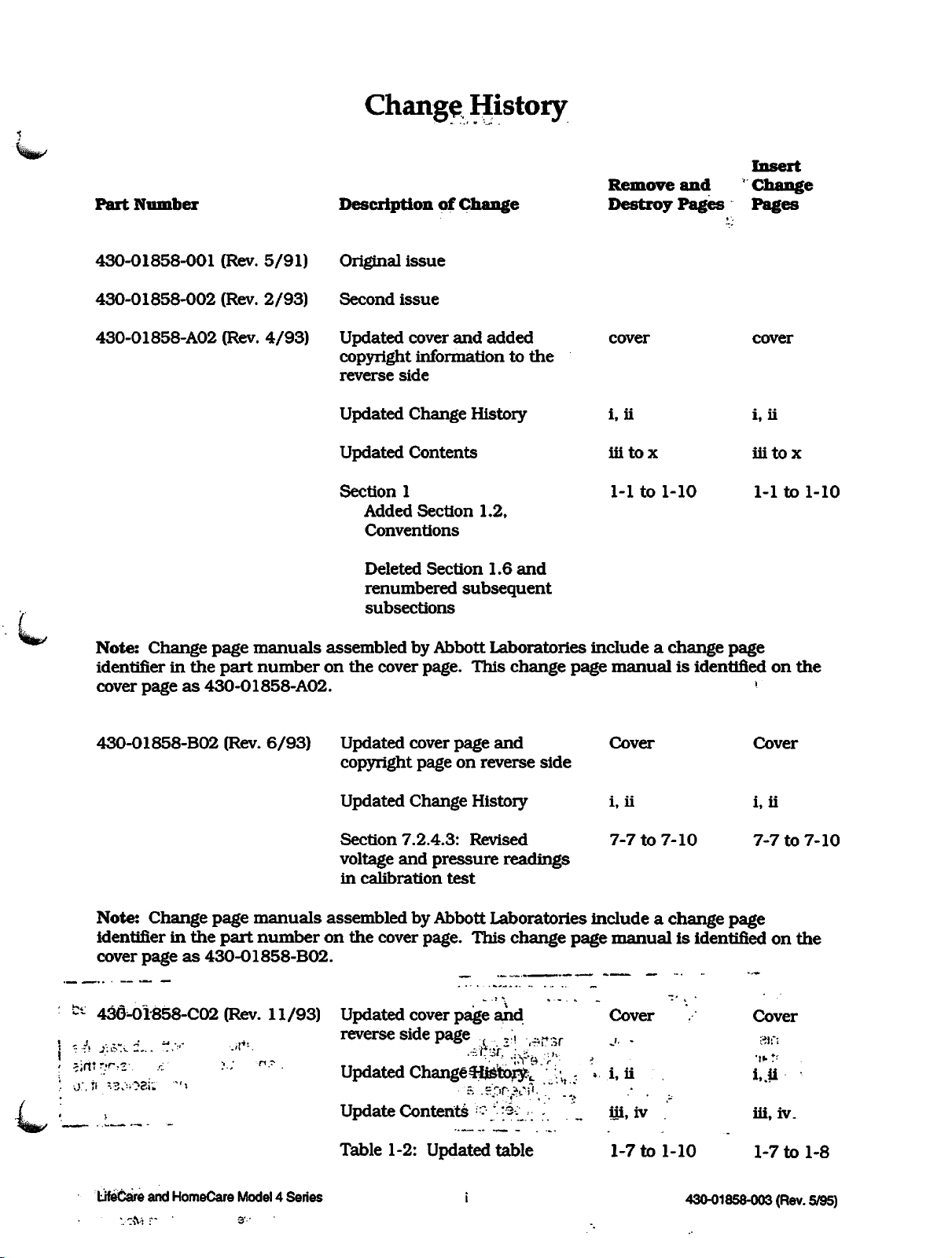
430-01858-001
430-01858-002
430-01858-A02
(Rev.
(Rev.
(Rev.
5/91)
2/93)
4/93)
Original
Second
Updated
copyright
reverse
Updated
Updated
Section
Added
Conventions
Deleted
renumbered
subsections
issue
issue
cover
and
added
informationtothe
side
Change
History
Contents
1
Section
Section
1.2,
1.6
subsequent
and
cover
i,
iii
1-1
cover
ii
tox
to
1-10
i,
iii
1-1
ii
tox
to
1-10
(
Note:
identifierinthe
cover
Change
page
part
manuals
number
pageas430-01858-A02.
assembledbyAbbott
on
the
cover
page.
Laboratories
This
change
includeachange
page
manualisidentifiedonthe
page
"^jp/
430-01858-B02
Note: Change page
identifierinthe
cover
pageas430-01858-B02.
'*•-
436^01858-C02 (Rev.
s;ritr.r?2-..
LifeCare
vita
n
and
r '
HomeCare
(Rev.
6/93)
manuals
part
number
?.;
^-
Model4Series
3':'
11/93)
Updated
copyright
Updated
Section
voltage
in
calibration
cover
page
pageonreverse
Change
7.2.4.3:
and
History
Revised
pressure
test
and
readings
side
Cover
i, ii i, ii
7-7
to
assembled by Abbott Laboratories include a
on
the
cover page.
Updated cover
reverse
Updated
side
Changeiijfeto^
Update Contents -\'-;^V:
Table 1-2:
This
page
page
Updated
.,
change
and
",:,
table
...H.^
':[\
r.
page
manual
Cover
J,
-
i,
ii
iii.
iv
1-7
to
Cover
7-10
change
7-7to7-10
page
is identifiedonthe
Cover
31 f;
i..U
iii,
iv.
1-
-10
430-01858-003 (Rev.5/95)
1-7
to
1-8
Page 4
Change History
Part
Number
DesciiptiotfbF6naiige
Remove
Destroy
Insert
and
Change
Pages Pages
s^ssr
Section
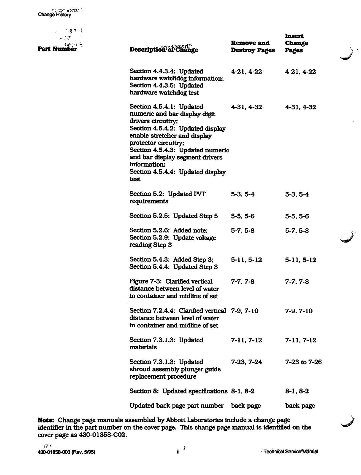
4.4.3.4: Updated 4-21,
hardware
Section
4.4.3.5:
hardware
Section
numeric
drivers
Section
enable
protector
Section
and
information;
Section
test
Section
requirements
Section
Section
Section
reading
4.5.4.1:
and
circuitry;
4.5.4.2: Updated display
stretcher
circuitry;
4.5.4.3:
bar
display
4.5.4.4: Updated display
5.2:
5.2.5:
5,2.6:
5.2.9: Update voltage
Step
watchdog
Updated
watchdog
Updated
bar
display
and
Updated
segment
Updated
Updated
Added
3
information;
test
digit
display
numeric
drivers
PVT
Step
5
note;
4-31,
5-3,
5-5,
5-7,
4-22
4-32
5-4
5-6
5-8
4-21,
4-22
4-31,4-32
5-3,
5-4
5-5,
5-6
5-7,
5-8
Note:
identifierinthe
cover
Change
page
part
pageas430-01858-C02.
manuals
number
Section
Section
Figure
distance
in
Section
distance
in
Section
materials
Section
shroud
replacement
Section
Updated
5.4.3:
5.4.4:
7-3:
container
7.2.4.4:
container
7.3.1.3:
7.3.1.3:
assembly
8:
Clarified
between
and
between
and
procedure
Updated
back
Added
Updated
page
assembledbyAbbott
on
the
cover
page.
Step
Step
vertical
levelofwater
midline
Clarified
levelofwater
midline
of
vertical
of
Updated
Updated
plunger
guide
specifications
part
number
Laboratories
This
change
3;
5-11,5-12
3
7-7,
set
7-9,
set
7-11,7-12
7-23,
8-1,8-2
back
includeachange
page
manualisidentifiedonthe
7-8
7-10
7-24
page
5-11,5-12
7-7,
7-9,
7-11,7-12
7-23
8-1,
back
page
7-8
7-10
to
8-2
page
7-26
430-01858-003 (Rev. 5/95)
Technical Sen/ice^Aaftiial
Page 5
'•i-j'
5/95)
(Rev.
430-01858-003
iii
4
Series
Model
and
HomeCare
JJeCare
:t«0.
..-,--•'•"l
/•^r.C
-•:
.3(V»v-
History
Change
Insert
Change
Pages Pages
and
Destroy
Remove
(Rev.
Third
issue
of
r
Change
Description
5/95)
430-01858-003
Part
Number
Page 6
Service
Manual.:.; j
Technical
IV
430-01858-003 (Rev. 5/95)
left
blank.
This
page
intentionally
>
i?3
J.A.~J
;>
Change-History
Page 7
Contents
Contents
.••o
^Il^/
Section
INTRODUCTION
1.1
1.2
1.3
1.4
1.5
1.6
1.7
Section
WARRANTY
Section
SYSTEM
Section
THEORY
4.1
43
1
SCOPE
CONVENTIONS
ACRONYMS
USER
ARTIFACTS
SERIES
INSTRUMENT
1.7.1
1.7.2
1.7.3
2
3
OPERATING
4
OF
GENERAL
4.1.1
4.1.2
4.1.3
4.1.4
EXTERNAL
4^.1
4^.2
4^.3
4.2.4
4.2.5
4.2.6
4.3
OPERATIONAL
4.3.1
43.2
4.33
4.4
MONITORS
4.4.1
AND
ABBREVIATIONS
QUALIFICATIONS
SPECIFIC
UNPACKING
INSPECTION
SELFTEST
OPERATION
FUNCTIONS
CASSETTE
FLOWDETECTOR
ALARMS
4.1.3.1
4.1.3.2
NUMERIC
ACC
FEATURES
INSTALLATION
MANUAL
AUDIBLEALARM
NURSE-CALL
AND
INTERFACE
CONNECTOR
NURSE-CALL
FLOW
RS-485
RS-232I/OPORT
20-MAI/OPORT
MODES
4.3.1.1
4.3.1.2
4.3.13
4.3.1.4
4.3.1.5
43.1.6
DETECTOR
DATAWAY
DESCRIPTION
OF
OPERATION
LOAD/OFF
SELFTESTMODE
LOCAL
REMOTE
BATTERY
SYSTEM
SILENCE/ASK
DATA
FLOW
4.4.1.1
4.4.1.2
4.4.1.3
4.4.1.4
RETENTION
AND
DETECTORS
MONITORING
FLOWDETECTOR
DROP
SIGNAL
CURRENT
SYNCHRONOUS
ALARM
BAR
DISPLAYS
PORTS
J23
JACK
J21
CONNECTOR
I/O
RECHARGE
CONTROL
CONTROL
DISCHARGED
FAILURE
FUNCTION
FUNCTION
AMPLITUDE
PROCEDURE
J22
CONNECTOR
MODE
MODE
MODE
MODE
MODE
SYSTEM
PROCESSOR
MODULATOR
DEMODULATOR
JlOl
,.,.
1-1
1-1
1-2
1-3
1-5
1-5
1-6
1-8
1-9
1-9
1-9
2-1
3-1
4-1
4-1
4-1
4-2
4-2
4-2
4-2
4-2
4-3
4-3
4-4
4-4
4-5
4-5
4-5
4-6
4-6
4-7
4-8
4-8
4-9
4-9
4-10
4-11
4-12
4-12
4-12
4-13
4-14
4-14
4-15
LifeCare
and
HomeCare
Model4Series
v
430-01858-003
(Rev.
5/95)
Page 8
Contents
4.4.2
4.43
4.5
ELECTRONICS
4.5.1
4.5.2
4.53
4.5.4
4.5.5
4.5.6
4.5.7
4.6
MECHANICAL
4.6.1
4.6.2
4.63
4.7
BATTERY
430-01858-003
4.4.1.5
4.4.1.6
4.4.1.7
PRESSURE
4.4.2.1
4.4.2.2
4.4.23
DROP
FLOW
FLOW
MEASURING
PRESSURE
PRESSURE
OCCLUSION
MALFUNCTION
4.43.1
4.4.3.2
4.43.3
4.43.4
4.4.3.5
4.4.3.6
4.43.7
INTERNAL
ROMTEST
POWER-UPTEST
HARDWARE
HARDWARE
SOFTWARE
MICROPROCESSOR
SUBSYSTEM
MPUPWA
4.5.1.1
4.5.1.2
4.5.1.3
4.5.1.4
4.5.1.5
MOTOR
4.5.2.1
4.5.2.2
4.5.2.3
4.5.2.4
DISPLAYPWA
DISPLAY
4.5.4.1
4.5.4.2
4.5.43
4.5.4.4
4.5.4.5
POWER
4.5.5.1
4.5.5.2
4.5.5.3
4.5.5.4
4.5.5.5
4.5.5.6
4.5.5.7
4.5.5.8
4.5.5.9
4.5.5.10
CURRENT
4.5.6.1
4.5.6.2
CONTROL
4.5.7.1
4.5.7.2
MICROPROCESSOR
MEMORY
MEMORY
MEMORY
I/O
PORTS
DRIVER
I/O
ADDRESS
INPUT
A/DCONVERTER
RS-485
DRIVER
HARDWARE
NUMERIC
DISPLAY
PROTECTOR
NUMERIC
DISPLAYTEST
SUPPLY
UNREGULATED
BATTERYPACK
BATTERY
DIODE
POWER
5
VDC
5
VDC
MOTOR
BATTERY
MEMORY
BOOST
AC
(MAINS)
DCOPERATION
SWITCHES
FRONT
REAR
SUBSYSTEM
CASSETTE
PUMPMECHANISM
MOTOR
AND
OPERATION
(Rev.
5/95)
AMPLITUDE
DETECTOR
ALGORITHM
SENSOR
SENSOR
ALARM
DETECTION
RAM
. . . . .
WATCHDOG
WATCHDOG
WATCHDOG
PRINCIPLES
CIRCUITRY
LATCH
PROTECTOR
PWA
DECODER
DATA
DATAWAY
POWER
REGULATOR
FAILURE
BUFFERS
PWA
WATCHDOG
AND
ENABLE
CIRCUITRY
AND
PWA
CHARGER
CONTROL
VOLTAGE
MONITOR
SUPPLY
CHARGER
BAR
BAR
SWITCH
DETECTOR
OPERATION
PANEL
PANEL
SWITCHES
SWITCHES
PRINCIPLES
MOTOR
OVERVIEW
THRESHOLD
PRESENCE
SYSTEM
PWA
PWA
ALGORITHM
CIRCUITRY
TEST
SANITY
CIRCUITRY
CIRCUITRY
...-.
PORT
DISPLAY
STRETCHER
DISPLAY
DC
POWER
CIRCUITRY
CIRCUITRY
CIRCUITRY
REGULATOR
CIRCUITRY
CIRCUITRY
PWA
. .
DRIVERS
DETECTION
(-004
AND
(-003
AND
TEST
CHECK
OF
OPERATION
.
CIRCUITRY
.
CIRCUITRY
DIGIT
AND
SEGMENT
SUPPLY
CIRCUITRY
CIRCUITRY
OF
OPERATION
vi
DETECTOR
HIGHER)
LOWER)
DRIVERS
DISPLAY
DRIVERS
CIRCUITRY
CIRCUITRY
...
Technical
Service
4-15
4-15
4-16
4-16
4-17
4-17
4-17
4-18
4-18
4-19
4-19
4-19
4-20
4-20
4-20
4-20
4-21
4-21
4-22
4-22
4-22
4-22
4-23
4-26
4-27
4-27
4-27
4-28
4-29
4-29
4-29
4-30
4-30
4-30
4-31
4-31
4-31
4-32
4-32
4-32
4-33
4-34
4-34
4-34
4-35
4-35
4-35
4-36
4-36
4-36
4-37
4-38
4-38
4-39
4-40
4-40
Manual
Page 9
Contents
\jjyjj~
Sections
MAINTENANCE
5.1 PREVENTIVE MAINTENANCE •'.'".'
5.1.1
5.1.2
5.1.3
5.2
PERFORMANCE
5.2.1
5.2.2
5.2.3
5.2.4
5.2.5
5.2.6
5.2.7
5.2.8
5.2.9
5.2.10
5.2.11
5.2.12
5.2.13
5.3
BATTERY
53.1
53.2
5.4
BATTERY
5.4.1
5.4^
5.4.3
5.4.4
5.5
PVTDATAFORM
AND
SERVICETESTS
INSPECTING THE PUMP
CLEANING
SANITIZING
EQUIPMENT
PUMP
DRY
CASSETTE
TEST
STARTUPTEST
PRESSURE
HIGH
AND
DELIVERY
PIGGYBACK
BATTERY
MALFUNCTION
ELECTRICAL
END
OF
MAINTENANCE
DEPTH
RECHARGING
CIRCUIT
TEST
LOW
BATTERY
BATTERY
THE
THE
VERIFICATION
AND
INSPECTION
SETUP
TEST
FLOW
AUDIBLE
EQUIPMENT
BATTERY
ALARM
ALARM
ACCURACY
TEST
CHARGING
SAFETY
PERFORMANCE
OF
DISCHARGE
ALARM
ALARM
SHUTDOWN
CHARGING
PUMP
PUMP
MATERIALS
TEST
AND
SILENCE
AND
(MODEL
TEST
SIMULATION
TEST
AND
REQUIRED
...];.
....."
....
....
TEST
LOW
TESTS
TEST
TEST
TEST
CIRCUIT
. . . .
4P
ONLY)
....
TEST
VERIFICATION
CHARGER
........
. . .
REQUIRED
SWITCH
FLOW
TEST
: ; .
. .
ALARM
.
TESTS
>:
:
:
TEST
TEST
\
.
(SIMULATED)
. . .
..:.......
.
. .
5-1
5-1
5-1
5-2
5-3
5-3
5-3
5-4
5-4
5-4
5-5
5-6
5-7
5-7
5-8
5-9
5-9
5-9
5-9
5-10
5-10
.
5-10
5-11
5-11
5-11
5-11
5-12
.
5-13
Section
TROUBLESHOOTING
6.1
6.2
6.3
6.4
6.5
6.6
6.7
6.8
Section
6
TECHNICAL
AUDIBLEALARMS
ALARM
ALARM
OBTAINING
PUMP
FVTTROUBLESHOOTING
TEST
TROUBLESHOOTING
CONNECTOR
7
REPLACEABLE
7.1
REPLACEABLE
7.2
ADJUSTMENT
7.2.1
7.2.2
7.2.3
7.2.4
TOOLS
SHROUD
SHROUD
PRESSURE
7.2.4.1
7.2.4.2
7.2.4.3
ASSISTANCE
CONDITIONS
CODES
AN
PARTS
AND
PARTS
PROCEDURES
AND
TAB
REAR
PRESSURE
CALIBRATION
CAUBRATION
ALARM
REPAIRS
LIST
MATERIALS
CHECK
TAB
SENSOR
HISTORY
v .
: .
. .
.
REQUIRED
ADJUSTMENT
CALIBRATION
SENSOR
CALIBRATION
(PRESSURE
.
AND
SENSOR
TEST
(PRESSURE SENSOR PWA-004
SETUP
PWA-003
AND
LOWER)
AND
HIGHER) . .
...
6-1
6-1
6-1
6-2
6-2
6-2
6-4
6-17
6-19
7-1
7-1
7-3
7-3
7-3
7-4
7-5
7-5
7-6
7-8
LifeCare
and
HomeCare
Model 4
Series
vii
430-01858-003 (Rev. 5/95)
Page 10
Contents
7.2.4.4
7.3
REPLACEMENT
7.3.1
7.3.2
7.3.2.1
7.3.2.2
7.3.2.3
7.33
7.3.4
7.3.4.1
7.3.4.2 FUSE
7.3.5
VELCRO
7.3.6
73.7
73.8
73.9
7.3.10
7.3.11
73.12
73.13
7.3.14
7.3.15
7.3.16
73.17
7.3.18
73.18.1
73.18.2
7.3.19
73.19.1
73.19.2
73.19.3
73.20
7.3.21
73.22
7.3.23
7.3.24
7.3.25
7.3.26
7.3.27
73.28
73.29
TOUCHSWTTCH
TRANSFORMER
7.330
7331
73.32
7.3.33
7.3.34
PRESSURE
SENSOR
TEST
PROCEDURES
SAFETY
REQUIRED
BATTERY
FUSE
AC
AC
NURSE-CALL
FLOW
FLOW
FEMALE
FLOW
CONNECTOR(S)
MAIN
POLE
POLE
AUDIBLE
SHROUD
ACCESSORY
CASE
PWA
AC
AC
AC
PIEZOELECTRIC
FEMALE
MAIN
MAIN
MAIN
FUSEHOLDERREPLACEMENT(115V~)
NURSE-CALL
PRESSURE
SET
RUBBER
MAINS
AND
EQUIPMENT
TOOLS
STANDARD
SPECIALTOOLS
MATERIALS
PACK
REPLACEMENT
FUSE
REPLACEMENT
AND
ANCHOR
POWER
POWER
CORD
CORD
CABLE
DETECTOR
DETECTOR
TERMINAL
DETECTOR
CONTROL
CLAMP
CLAMP
KNOB
SHAFT
ALARM
ASSEMBLY
(ACC)
REPLACEMENT
ONE-PIECE
CLAMSHELL
REPLACEMENT
POWER
DISPLAY
MOTOR
MOTHERBOARD
POWER
(MAINS)
POWER
CORD
POWER
CORD
TERMINAL
CONTROL
CONTROL
CONTROL
JACK
LEVEL
TYPE
SWITCH
FOOT
RECEPTACLE
AND
MATERIALS
HANDTOOLS
REPLACEMENT
FUSE
DRAWER
PAD
REPLACEMENT
STRAIN
PLUG
ASSEMBLY
ASSEMBLY
CONNECTOR
REPLACEMENT
KNOB
LEVEL
CASE
SUPPLY
PWA,
DRIVER
REPLACEMENT
RETAINER
PANEL
ALARM
CONNECTOR
SWITCH
SWITCH
SWITCH
REPLACEMENT
ASSEMBLY
REPLACEMENT
REPLACEMENT
REPLACEMENT
REPLACEMENT
SWITCH
PLUNGER
CONNECTOR
REPLACEMENT
CASE
PWA
DISPLAY
PWA
PWA
CORD
REPLACEMENT
REPLACEMENT
REPLACEMENT
REPLACEMENT
SELECT
REPLACEMENT
PAD
REPLACEMENT
ASSEMBLY
PRECAUTIONS
(115
RELIEF
REPLACEMENT
PLUG
REPLACEMENT
REPLACEMENT
REPLACEMENT
REPLACEMENT
REPLACEMENT
CLIP
SHAFT
SHAFT
WAFER
SWITCH
V~)
REPLACEMENT
BUSHING
REPLACEMENT
AND
CLOSED
HOUSING
REPLACEMENT
GUIDE
DRIVER
P10
REPLACEMENT
(OR
PINS)
PWA,
(115
V~)
REPLACEMENT
AND
CLOSED
ASSEMBLY
ASSEMBLY
REPLACEMENT
REPLACEMENT
(MICRO
REPLACEMENT
(100
V~,
REPLACEMENT
ENTRY
AND
MALE
REPLACEMENT
MPU
(100V-,
ENTRY
REPLACEMENT
LUBRICATION
ONLY)
PWA,
220
(115
(100
PIN
V~)
V~)
V~,
220
AND
220
V~)
(115
V~)
V~)
...
...
. .
7-10
7-11
7-11
7-11
7-12
7-12
7-12
7-13
7-14
7-14
7-15
7-15
7-16
7-16
7-17
7-17
7-18
7-19
7-20
7-20
7-21
7-22
7-23
7-24
7-26
7-26
7-28
7-30
7-30
7-31
7-33
7-34
7-35
7-36
7-36
7-38
7-39
7-40
7-43
7-44
7-45
7-46
7-46
7-47
7-48
7-49
Section
8
SPECIFICATIONS
430-01858-003
(Rev.
5/95)
viii
Technical
Service
8-1
Manual
Page 11
Rgures
^jjgs/
Section
DRAWINGS
Section
INDEX
9
10
Figures
Figure
Figure
Figure4-3. Pump Cassette
Figure5-1. DeliveryAccuracy Test Setup
Figure7-1. Shroud Tab Check
Figure7-2. Pressure Sensor AdjustmentResistors
Figure7-3. Calibration Test Setup
Figure7-4. Battery Pack Replacement
Figure
Figure
Figure
Figure 7-8. ACC.Connector Pin Arrangement
Figure7-9. Rear Panel Screw Removal (One-Piece Case)
Figure 7-10.
Figure
Figure
Figure
Figure
Figure 7-15.
Figure
Figure7-17.ACPower Cord Replacement
Figure7-18.Touchswitch Panel Replacement
Figure7-19.Piezoelectric AlarmReplacement
Figure
Figure 7-21.Main Control
Figure 7-22.Main Control Switch
Figure 9-1.
Figure 9-2. Schematic,
Figure 9-3. Schematic,
Figure 9-4. Schematic, Interconnect, International, Micro
Figure 9-5. Schematic, Pressure Sensor
Figure 9-6. Schematic, Motherboard
Figure 9-7. Schematic, MPU
Figure 9-8. Schematic, MPU
Figure 9-9. Schematic,
Figure 9-10. Schematic, Motor Driver PWA, Series 4
Figure 9-11.Schematic,
Figure 9-12.Schematic, Display
Figure 9-13. Schematic,
Figure 9-14.Schematic, Power
Figure 9-15.Schematic, Current Boost Charger,
Figure 9-16.IPB for
4-1.
FlowDetectorSchematicDiagram
4-2.
PowerControl Circuitry
7-5.
Main Control Knob Removal
7-6.
PoleClamp Knob Removal
7-7.
Shroud AssemblyPlunger Guide Replacement
Removing
7-11.
Case Screw Removal (Clamshell Case)
7-12.
Openingthe Clamshell Case
7-13.
Shield Removal
7-14.
Heat
PWA
7-16.
Motherboard PWA Removal
Chassis From Cover
Sink
Screw Removal
Removal
(115
7-20.
Main Control Switch Shaft Assembly
Block
Diagram, Series 4
the
Switch
System
System
Motor
Display
Display
Pump
Shaft
Assembly
Shaft
Assembly
Interconnect,
Interconnect, Micro 4/MDL4
PWA,
PWA,
Series 4
PWA,
Micro 4/Model4
Driver
Supply
PWA,
PWA,
Driver
PWA,
MDL
Micro 4
PWA, Micro
PWA,
PWA,
Model
Series 4 .
Micro
4
Series 4
Volt)
with
E-Ring Removal
4P
Micro
4/Model
4/Model
4/Model
MDL
4/PCA
Switch
4/MDL
4
4
Housing
4
4
Removed
9-1
10-1
4-14
4-33
4-39
5-5
7-4
7-6
7-8
7-14
7-20
7-21
7-24
7-26
7-27
7-28
7-29
7-29
7-30
7-31
7-32
7-33
7-35
7-37
7-39
7-42
7-42
7-43
9-3
9-5
9-9
9-13
9-17
9-21
9-25
9-29
9-31
9-33
9-35
9-39
9-43
9-45
9-65
9-69
LifeCare
and
HomeCare
Model4Series
ix
430-01858-003
(Rev.
5/95)
Page 12
Tables
Tables
Table
1-1.
Conventions
Table
1-2.
Model 4 Series CaseTypes and I/O Capabilities
Table 1-3. Series Specific Features - Model 4 Series
Table 4-1. ACC. Connector
Table 4-2. User Controls and Operating Modes
Table 4-3.
Table
4-4.
ASK
Function Messages
I/O
Address
Table 4-5. Numeric and Bar Displays
Table 5-1. Cleaning Solutions
Table
6-1.
Alarm
Codes
Table 6-2. Troubleshooting
Table 6-3. Troubleshooting Fluid Flow
Table 6-4. Troubleshooting Battery Operations
Table
6-5.
Troubleshooting
Table 6-6. Troubleshootingthe Pump Displays
Table 6-7. TroubleshootingExternal Controls
Table 6-8. Troubleshooting the PumpTouchswitches
Table 6-9. Troubleshooting the Pump Mechanism
Table
6-10.
Troubleshooting the Dataway Function (RS-485 Only)
Table 6-11.Troubleshooting
Table
6-12.
Troubleshooting Miscellaneous Conditions
Table 6-13.Troubleshooting
Table 6-14.
Test
Connector
Table9-1. Drawings
Table9-2. IPB for
the
Table
(J23)
Pump
J23
Pin Arrangement
Audible
Alarms
Core Failures
the
Nurse-Call Alarm
with
the
PVT
Pin
Assignments
1-2
1-6
1-7
4-4
4-6
4-11
4-24
4-29
5-2
6-3
6-4
6-5
6-9
6-11
6-12
6-13
6-13
6-13
6-15
6-16
6-16
6-18
6-19
9-1
9-89
430-01858-003 (Rev. 5/95)
Technical
Service
Manual
Page 13
^ Section1
INTRODUCTION
LifeCare®
are
identifiedbythe
•
Q
•
•
The
Model4except
LifeCare Micro
and
LifeCare
LifeCare
LifeCare
HomeCare
LifeCare
HomeCare
Model
Model
Micro
Model
Model4isabaseline
that
features
Model4Hversionofthe
For
details
Features.
about
the
1.1
SCOPE
The
manualisorganized
Model
following
4
4P
4H
Dual
Rate
delivery
Model4
various
into
4 SeriesInfusionPumps, herein
model
11
designations:
infusion
automatic
rates
from
hasalimited
pump
configurations,
sections:
pump.
The
LifeCare Model 4Pissimilartothe
piggybackingisavailableonModel 4P.
0.1to99.9
delivery
milliliters
rate
range
refertoSection 1.6,
referred
per
for
home
to asthe pump,
hour
(ml/hr).
care
applications.
Series
The
The
Specific
•
Section
Q
Section2Warranty
•
Section3System
•
Section4TheoryofOperation
•
Section
Q
Section6Troubleshooting
•
Section7Replaceable
•
Section8Specifications
Q
Section9Drawings
•
Section
•
Technical
The
material in
testing,
adjustment
Specific
system
1
Introduction
5
Maintenance
10
Index
Service
this
various
Bulletins
manual
service
procedures, troubleshooting,
instructions
operating
for
manuals.
Operating
and
Parts
is limited to technical information necessary for
tests,
pump
Manual
Service
and
interpreting
Tests
Repairs
and
system
alarm
and
authorized repairsonthe
operation are providedinthe
status
LifeCare
messages,
pump.
and
HomeCare
battery
field
Technical
Service
Manual
1-1
430-01858-003
(Rev.
5/95)
Page 14
Section1INTRODUCTION
Ifa problem in
contact
Abbott
pump
operation cannot be resolvedusing the information in this manual,
Laboratories (see Section 6.1, Technical Assistance).
Note: Figures are rendered as graphic representations to approximate the actual product;
therefore, figures may
exactly reflect the product. Display screens
and
touchswitch
not
labels may vary slightly,depending on the configuration ofthe pump system in use.
1.2
CONVENTIONS
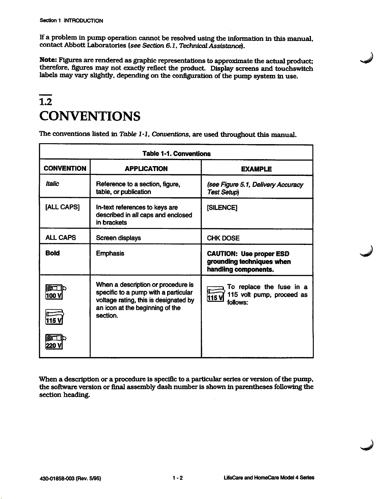
The conventions listed in Table 1-1, Conventions, are used throughout this manual.
Table
1-1.
Conventions
CONVENTION
Italic
[ALLCAPS]
Reference to a section, figure,
table,orpublication
In-text references to keys
described
in
brackets
APPLICATION
in all
caps
and
are
enclosed
EXAMPLE
(see
Figure5.1, DeliveryAccuracy
Test Setup)
[SILENCE]
ALL
Bold
loovl
115Vf
220
V|
CAPS
Screen
Emphasis
When
specific to a
voltage
an
iconatthe
section.
Whenadescriptionora
the
software
section
versionorfinal
heading.
displays
a description or procedure is
pump
with a particular
rating, this is
beginning of
designated
the
by
procedureisspecific to a
assembly
dash
numberisshowninparentheses
CHK
CAUTION:
grounding
handling
—d
j^vj
particular
DOSE
Use
proper
techniques
ESD
when
components.
To
115
'
follows:
replace
volt
the
pump,
fuse
proceed
seriesorversionofthe
following
in a
as
pump,
the
430-01858-003 (Rev. 5/95)
1-2
LifeCare
and
HomeCare
Mode!4Series
Page 15
1.3 ACRONYMS AND ABBREVIATIONS
Throughout
information
A
WARNING
ALL
this
as
TIMES.
follows:
THREATENING.
CAUTION:
contains
Note: A
1.3
A
CAUTION
information
note
highlights
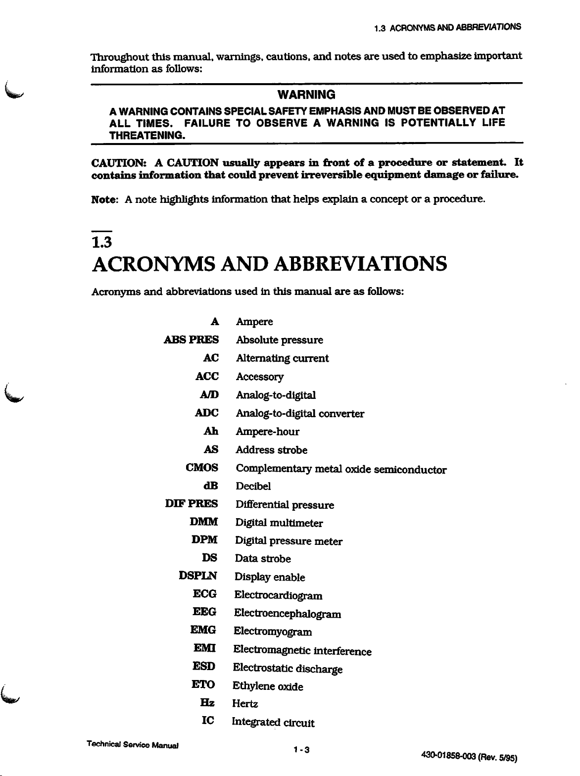
ACRONYMS
Acronyms
and
abbreviations
ABSPRES
manual,
CONTAINS
FAILURE
that
warnings, cautions,
WARNING
SPECIAL
TO
usually
could
information
AND
usedinthis
A
Ampere
Absolute
SAFETY
OBSERVE
appears
prevent
that
ABBREVIATIONS
pressure
and
notes
EMPHASIS
A
WARNING
in
front
ofaprocedure
irreversible
helps
explainaconceptora
manual
areasfollows:
are
used
AND
MUST
IS
POTENTIALLY
equipment
to emphasize
BE
OBSERVED
or
statement.
damage
procedure.
important
AT
LIFE
or
failure.
It
CMOS
DIFPRES
DMM
DPM
DSPLN
ECG
EEG
EMG
EMI
ESD
ETO
AC
ACC
A/D
ADC
Ah
AS
dB
DS
Hz
IC
Alternating
current
Accessory
Analog-to-digital
Analog-to-digital
converter
Ampere-hour
Address
Complementary
Decibel
Differential
Digital
Digital
Data
Display
strobe
pressure
multimeter
pressure
strobe
enable
metal
meter
oxide
Electrocardiogram
Electroencephalogram
Electromyogram
Electromagnetic interference
Electrostatic discharge
Ethylene
Hertz
Integrated
oxide
circuit
semiconductor
Technical Service Manual
1 _ o
430-01858-003
(Rev.
5/95)
Page 16
Section 1
INTRODUCTION
MAL
LEDCATH
ALM
CODE
MFULL
INIT
IOA
IOD
EPB
IRQ
kHz
kPa
KVO
LED
LSB
mA
I/O
IV
Initiate
Input/output
Input/output
Input/output
Illustrated
Interrupt
Intravenous
Kilohertz
Kilopascal
Keep
Light
LED
Least
Milliampere
Malfunction
Message
request
vein
emitting
cathode
significant
full
parts
open
alarm
address
data
breakdown
diode
bit
code
MHz
ml/hr
MPU
MSB
NCALL
OKBATT
ml
ms
mV
N/A
NC
NO
No.
P/N
psi
psig
Megahertz
Milliliter
Milliliter
per
Microprocessor
Millisecond
Most
significant
Millivolt
Not
applicable
Normally
Nurse
Normally
Number
OK
Part
Pounds
Pounds
call
battery
number
closed
open
per
per
square
square
hour
unit
bit
inch
inch
gauge
i.nn'a
(Do\i
PVC
PVT
PWA
PWB
PWRCTL
PWRUP
c,iQx,\
Polyvinyl
Performance
Printed
Printed
Power
Power
wiring
wiring
control
up
chloride
verification
assembly
board
1
.4
test
LifeCareand HomeCare
Model
4 Series
Page 17
1.4
USER
QUALIFICATIONS
\|§py
SFTWRREV
UART
VMEM
VMOT
WDSTB
RAM
ROM
RST
RTS
TRE
VDC
SD
SW
HA
V
jiF
Random
Read
Reset
Requesttosend
Serial
Software
Switch
Transmit
Universal
Volt
Volt
Voltage
Motor
Watchdog
Microampere
Microfarad
access
only
Data
revision
enable
asynchronous
direct
memory
voltage
memory
current
strobe
memory
receiver/transmitter
requester
Microsecond
\xs
1.4
USER
The
Model 4 Series
of
licensed
in
the
QUALIFICATIONS
physicians,
useofthe
infusion
andbylicensedorcertified
pump
pumps
andinthe
are
administration
1.5
ARTIFACTS
Nonhazardous,
administered
standards,
EEG
machines.
the
monitoring
its
sensing
physiological signals. To determine if
causedbythe
thatitis temporarily
it
was
probably
maintenance
appropriate
low-level
using
but
may
create
These
machineisnot
electrodes,
pump
caused
of
the
monitoring
electrical
potentials
infusion devices. These potentials
artifactsonvoltage-sensing
artifacts
varyata
operating
these
instead
not
deliveringfluid.
artifacts
of some
by electronic noise generated by
monitoring
system
equipment
documentation
for
useatthe
healthcare
of
intravenous
are
commonly
equipment
rate
thatisassociated
correctlyorhas
may
be
accentuated
the
abnormalityinthe
other
sourceinthe
Disappearanceofthe
should
for
eliminate
setup
directionorunder
professionals
(IV)
fluids.
observed
are
well
within
suchasECG,
with
the
looseordefective
so
as
to
monitoring
environment,
abnormality
the
pump.
the
artifact
and
maintenance
the
supervision
who
are
trained
when
fluids
accepted safety
EMG,
infusion
rate.
connections
simulate
actual
equipment
set
the
pump
indicates
Proper
setup
Refer to
instructions.
are
and
If
to
is
so
that
and
the
Nj|^j^
Technical
Service
Manual
1-5
430-01858-003 (Rev. 5/95)
Page 18
Section1INTRODUCTION
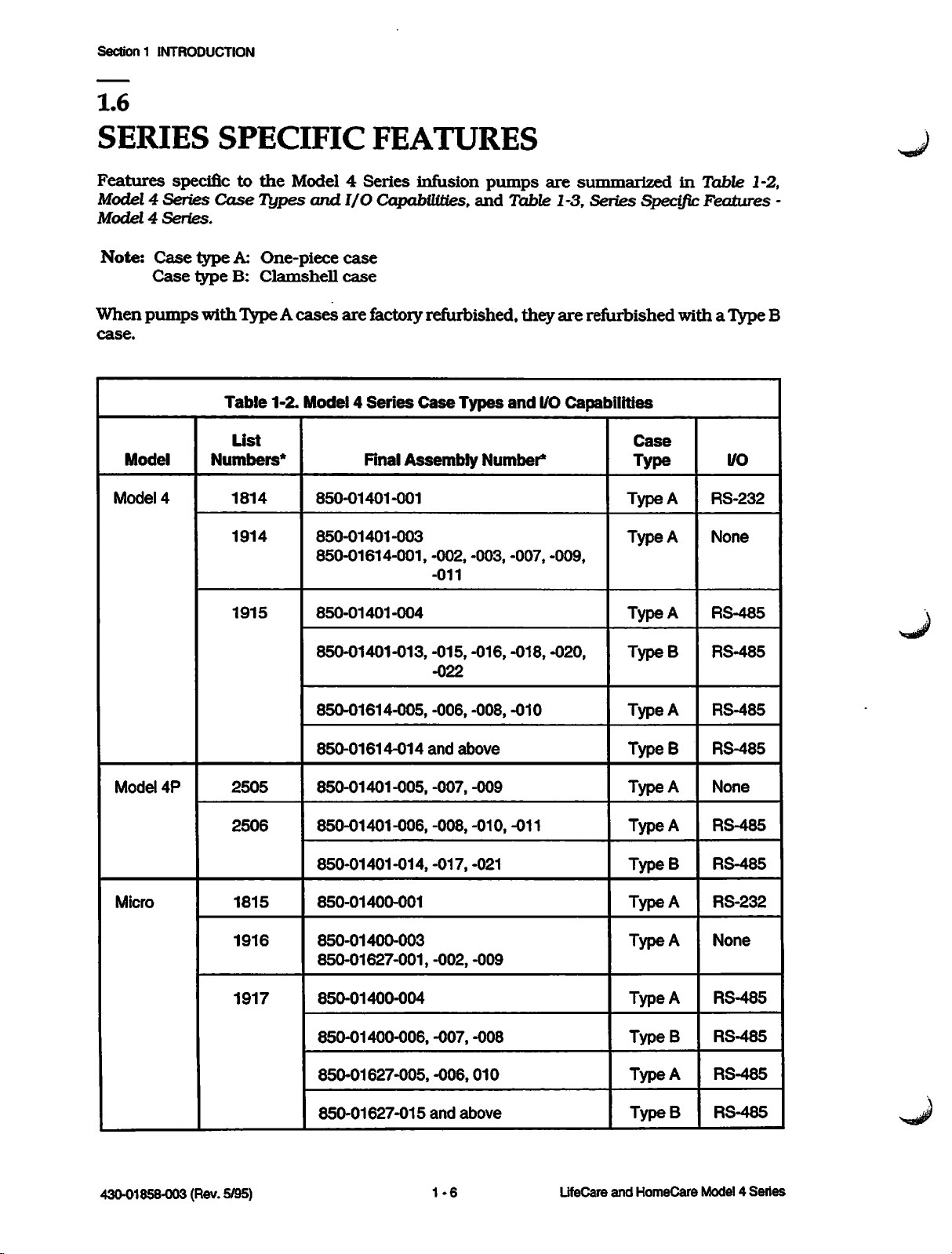
1.6
SERIES
Features
Model 4 Series
Model4Series.
Note:
When
case.
Model
Model
specific to
Case
Case
pumps
4
SPECIFIC
the
Case
Types
type
A:
One-piece
type
B:
Clamshell
with
Type A
Table
Numbers*
1-2.
List
1814
1914
FEATURES
Model 4
and
cases
Model4Series
Series
I/O
Capabilities,
case
case
are
factory refurbished,
Final
850-01401-001
850-01401-003
850-01614-001,-002,
infusion
Case
Types
Assembly
-011
pumps
and
Number*
-003,
are
summarized
in
Table 1-3, Series Specific Features -
they
are
and
-007,
refurbished
I/O
Capabilities
-009,
Type
Type
with
Case
Type
A
A
Table 1-2,
a Type B
I/O
RS-232
None
Model
Micro
4P
1915
2505
2506
1815
1916
1917
850-01401-004
850-01401-013,
850-01614-005,
850-01614-014
850-01401-005,
850-01401-006,
850-01401-014,-017,-021
850-01400-001
850-01400-003
850-01627-001,
850-01400-004
850-01400-006,
-015,
-022
-006,
and
-007,
-008,
-002,
-007,
above
-016,
-008,
-009
-010,
-009
-008
-018,
-010
-011
-020,
Type
TypeB
Type
TypeB
Type
Type
TypeB
Type
Type
Type
TypeB
A
RS-485
RS-485
A
RS-485
RS-485
A
None
RS-485
A
RS-485
RS-232
A
None
A
RS-485
A
RS-485
430-01858-003 (Rev. 5/95)
850-01627-005,
850-01627-015
-006,
and
1-6
010
above
LifeCare
and
Type
TypeB
HomeCare
A
Mode!4Series
RS-485
RS-485
Page 19
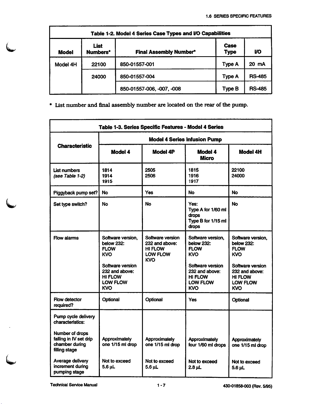
Table
1-2.
Model4Series
Case
Types
and
1.6
I/O
Capabilities
SERIES
SPECIFIC
FEATURES
N||^/
Model
*
Model
List
List
(see
4H
number
Characteristic
numbers
Table 1-2)
Piggyback pump
List
Numbers*
22100
24000
and
final
Table
set?
1814
1914
1915
No
850-01557-001
850-01557-004
850-01557-006,
assembly
1-3.
Series
Model
4
Final
Assembly
number
Specific
Model 4
2505
2506
Yes
Number*
-007,
-008
are locatedonthe
Model4Series
•
Infusion
Model
Features
Series
4P
Case
Type
Type
Type
TypeB
rearofthe
pump.
Pump
Model
1815
1916
1917
No No
4
Micro
22100
24000
A
A
Model
I/O
20
mA
RS-485
RS-485
4H
Set
type switch?
Row
alarms
Row
detector
required?
Pump
cycle delivery
characteristics:
Numberofdrops
falling in IV
chamber
filling
set
during
stage
drip
No
Software
below
FLOW
KVO
Software
232
HI
LOW
KVO
and
FLOW
FLOW
version,
232:
version
above:
Optional
Approximately
one
1/15
ml drop
No
Software
232
HI
LOW
KVO
and
FLOW
FLOW
version
above:
Optional
Approximately
one
1/15 ml drop
Yes:
Type A for 1/60ml
drops
TypeB
for
1/15
ml
drops
Software
below
FLOW
KVO
Software
232
HI
LOW
KVO
Yes
232:
and
FLOW
FLOW
version,
version
above:
Approximately
four 1/60 mldrops
No
Software
below
FLOW
KVO
Software
232
HI
LOW
KVO
232:
and
FLOW
FLOW
version,
version
above:
Optional
Approximately
one
1/15 ml drop
Average delivery
increment during
pumping
Technical
stage
Service
Manual
Nottoexceed
5.6
u.L
Nottoexceed
5.6
uL
1-7
Nottoexceed
2.8
\iL
Nottoexceed
5.6
^L
430-01858-003 (Rev. 5/95)
Page 20
Sectionl
INTRODUCTION
Characteristic
KVO
rate
Note: Rate may be
lessifset
rateislower
delivery
Flow monitoring:
Operating angle
from
vertical
Row
alarm
monitoring
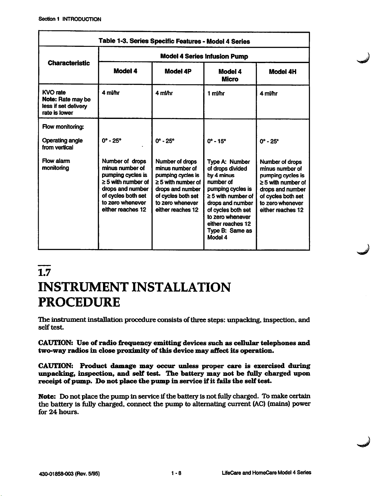
Table
1-3.
Model
4ml/hr
0°-25°
Number of
minus
number
Series
4
drops
pumping cycles is
> 5
with
number
drops
and
number
of
cycles
both
to
zero
whenever
either
reaches
Specific
4ml/hr
0°-25°
Number of drops
of
minus
pumping cycles is
of
> 5
drops
set
of cycles both
to
12
either
Features - Model 4
Model 4
Model
with
zero
number
number
and
number
whenever
reaches
Series
4P
of
set
12
Infusion
Model
Micro
1
ml/hr
0°-15°
Type A: Number
ofdrops divided
by 4 minus
number
of
pumping cycles is
> 5
with
drops
and
ofcycles both
to
zero
either
reaches
TypeB:
Model
Series
Pump
4
of
number
number
whenever
Same
4
4
0°-25°
Numberof drops
minus
pumping cycles is
> 5
drops
of
of
to
set
either
12
as
Model
ml/hr
with
cycles
zero
number
number
and
number
both
whenever
reaches
4H
of
of
set
12
1.7
INSTRUMENT
PROCEDURE
The
instrument
self
test.
CAUTION:
two-way
CAUTION:
unpacking,
receipt
Note:
the
for
of
Do
battery
24
hours.
radiosinclose
installation
Useofradio
Product
inspection,
pump.
not
Do
place
is fully charged,
INSTALLATION
procedure
frequency
proximity
damage
and
self
not
place
the
pumpinserviceif
connect
may
the
consistsofthree
emitting
of
this
device
occur
test.
pump
the
unless
The
in
the
batteryisnot
pump
steps:
devices
may
such
affect
proper
battery
may
serviceifit
to alternating
unpacking,
as
cellular
its
operation.
care
is
not
be
fully
fails
the
self
fully
charged.Tomake
current
inspection,
telephones
exercised
charged
test.
(AC)
(mains) power
and
and
during
upon
certain
430-01858-003 (Rev. 5/95)
1-8
LifeCare
and
HomeCare
Model4Series
Page 21
mjy-y
1.7.1
UNPACKING
Use
care
when
for
returning
container
1.7.2
the
also
INSPECTION
unpacking
pumptothe
the
pump.
factoryincaseitis
containsacopyofthe
Retain
system
1.7
INSTRUMENT
the
packing
damagedorfails
operating
manual.
slip
and
INSTALLATION
save
all
the
self
packing
test.
The
PROCEDURE
material
shipping
Inspect
the
the
delivering
CAUTION:
damaged;
1.7.3
SELF
contact
TEST
Note:Donot
the
self
test,
1.
Connect
2.
Connect
3.
Set
the
medium,
4.
Turn
5.
The
operations:
-
Initializes
been
packing
carrier
Inspect
place
proceed
the
the
AUD. ALM.
or
the
main
pump
reached
container
immediately.
the
pump
Abbott
the
power
flow
Laboratories
pumpinservice
as
follows:
cord
detectortothe
switchonthe
high.
control
switch
automatically
all
data
except
for
shipping
for
damage.
to a
properly
enters
historyifthe
damage.
(see
until
FLOW DET.
backofthe
to
LOCK/ON.
the
Should
Do
not
Section
the
self
grounded
pumptothe
self-test
four-hour
any
use
the
6.1,
Technical
test
has
AC
(mains)
receptacle
mode
data
damagebefound,
pumpifit
Assistance).
been
conducted.
outlet.
on
the
backofthe
desired
and
retention
volume
performs
interval
appears
To
level: low,
the
following
contact
to
be
conduct
pump.
has
-
-
-
-
-
If
the
Section
Technical
Tests
Checks
Illuminates
legends
Activates
Checks
pump
6.1,
Service
fails
Technical
random
failure
audible
critical
the
Manual
access
monitor
all
numeric
alarm
data
self
test,donot
Assistance).
memory
test
elements,
integrity
(RAM)
status
message
placeitin
1-9
and
read
display
service;
only
contact
memory
elements,
Abbott
(ROM)
and
front
Laboratories
430-01858-003
panel
(Rev.
(see
5/95)
Page 22
4
Series
Model
and
HomeCare
UfeCare
1-10
430-01858-003 (Rev. 5/95)
left
blank.
This
page intentionally
Section
1 INTRODUCTION
Page 23
^ Section 2
WARRANTY
Subject
Abbott,
and
periodofone
a
in
purchase.
fitness
Purchaser's
product
such
the
to
the
terms
warrants
be
free
from
year
material
causebebasedincontract,
price
and
Abbott
for a
particular
exclusive
Innoevent
of
workmanship
such
and
that
(a)
defectsinmaterial
after
makes
purpose,orany
remedy
shall
product,
consequential, or special
Warranty
The
altered,
judgment,
been
The
performs or
having
documentation
repairor
items
product
foregoing
or
to
altered,
foregoing
been
other
used
returnedtoAbbott
warranty
other
affect
effaced,
its
or
warranty
attempts
to perform
trained
and
approved spare parts. For purposesofthe
service"
means
stabilityorreliability,orin
by
suchasbatteries, flow detectors, detachable AC power cords,
conditions
the
product
purchase,
under
no
other
shall
Abbott's
and
herein,
shall
and
workmanship
and
(b)
the
normal
warranties,
other
be,atAbbott's
liability
negligence,
in
no
event
arising
damagesorlosses
mustbeproperly
shallbevoidinthe
than
in
accordance
removed.
event
shallalsobevoidinthe
any
majorrepair or
an
authorized
any
repairor service
representative
Abbott
Laboratories,
conformtoAbbott's
under
replaceable
use
and
service
expressorimplied,asto
matter.
option,
outofany
strict
liability,
shall
Abbott
or for
lost
packaged
the
product
with
product
the
event
event
any
other
normal
battery
the
shallbefree from
for a
repairorreplacementofthe
cause
other
tortorotherwise)
be
business,
and
has
been
manuals
the
serialorlot
person,
including
serviceonthe
of
Abbott
preceding sentence, "major
other
than
the
replacementofaccessory
herein
standard
use
and
periodof90
merchantability,
whatsoever
liable
for
revenues,
sent
freight prepaid.
misused,
so
as,
the
product
and
and
patient
referredtoas
specifications
service
days
incidental,
for
defects
after
(whether
exceed
or profits.
damaged,
in
Abbott's
number
has
Purchaser,
without
using
Abbott
pendants.
In
providing
responsibility or liability for
or service, regardlessofwhether
service. It
representative performingrepair or service is
Technical Service Manual 2 -1 430-01858-003(Rev.5/95)
any
is
understood
parts
for repair or service
the
actions or inactionsofthe
such
person
and
acknowledged
notanauthorized
has
of
been
that
the
product,
person performing
trained to perform
any
person
agentofAbbott.
Abbott
other
shall
such
than
have
such
repair or
an
no
repair
Abbott
Page 24
LifeCareand HomeCare Model4 Series
2-2
430-01858-003 (Rev. 5/95)
left
blank.
This
page
intentionally
2
WARRANTY
Section
Page 25
430-01858-003 (Rev. 5/95)
-1
Technical Service Manual 3
the
of
Operating
Assistance).
(see
Section 6.1,
a copy
insert
System
Laboratories
reference,
Abbott
contact
here.
For
convenient
MANUAL
available,
manual
pump.
every
HomeCare Model 4 Series Infusion Pumps
and
OPERATING
is
not
manual
operating
with
LifeCare
system
included
of
the
Technical
If
an
operating
appropriate
Manual is
A
copy
SYSTEM
^ Section 3
Page 26
Series
(Rev.
and
Model 4
HomeCare
3 - 2 LifeCare
5/95)
430-01858-003
left
blank.
This
page
intentionally
MANUAL
OPERATING
3
SYSTEM
Section
Page 27
Section
4
THEORY
This
section
Related
general
operation,
mechanical
Note:
an
Whenasignal
active
4.1
GENERAL
The
Model4Series
housed
mechanical
include
driver
The
pumping
(one
1/15
mechanism.
pumping
motor
milliliter
describes
drawings
functionsofthe
monitors
low
positive
printed
are
subsystem
signal.
displacement
subassemblies
wiring
mechanism
volumeiscalculatedasa
revolution
(ml)offluidina
OF
the
providedinSection 9, Drawings.
pump
and
detectors,
principlesofoperation.
nameisfollowedbyan
OPERATION
theory
of
operation
and
providesabrief
electronics
for
subsystem
asterisk,
FUNCTIONS
infusion
assemblies
pump
pump.
used
for
operation
(PWA),
contains
The
motor
the
electromechanical
driverishoused
and
controlofthe
battery
is stepper-motor driven to
functionofthe
equals
one
primed
pump
pump
stroke
chamber).
the
Model4Series
The
theoryofoperation
overviewofexternal
principles
suchasINIT ,
with
pump.
pack,
the
display
enableasimple
numberofstepsofthe
which
equals
the
drivers
all
The
panel,
control
of
asterisk
the
displacement
infusion
interface
operation,
withacassette
electrical
subassemblies
and
pump.
describes
ports,
and
indicates
and
the
pump
logic. The
stepper
motor
of
N^ggi/
The
flow
detector
to
the
numberofmotor
motor
number
revolutions
of
drops
DELIVERED
4.1.1
CASSETTE
The
cassetteisdesigned
An
air-trap
trappedinthe
chamber.
open,
resultinginno
pumpedtothe
The
cassette
compression
be
carried
pump
on
the
chamber
The
into
operation
model
monitors
fluid drops. The control logic
revolutions.
by
more
than
by
more
light
emitting
holds
chamber,anair
compressibilityofthe
deliveryofsolution.
patient.
must
be
than
diode
withanoutlet
air
bubble
correctly
chamberorfails to
the
compression
stops
and
a flow/KVO
and
versionofthe
When
four,
four, a flow
(LED)
bubblesoroutgassing
the
or
the
display
valve
that
numberofdrops
number
alarm
indicates
requires
maybecarried
air
primed.
clear
sufficient
chamber.
pump.
bubble
alarm
prevents
This
outlet
Incorrect
air
from
In
either
or low flow/KVO
compares
of
motor
is
generated
the
natureofthe
hydraulic
from
solution.
through
the
outlet
valve
feature
cassette
the
air
case,ifthe
the
exceeds
revolutions
pressuretooperate.
the
cassettetothe
valve
prevents
priming
trap,
permitting
flow
detectorisattached,
alarm
numberofdrops
the
number
exceeds
and
the
VOLUME
flow problem.
If
too
much
pumping
from
being
air
from
leaves
air
in
the
sounds,
depending
the
air
forced
being
the
air
to
of
is
Technical Service Manual
4-1
430-01858-003 (Rev. 5/95)
Page 28
Section4THEORY
4.1.2
OF
OPERATION
FLOW DETECTOR
The
flow
detector
providesacomparative
rateiscorrect
clean,
often
Useofthe
Table 1-3,
4.1.3
dry,
and
tracedtodirtyorimproperly
flow
Series
ALARMS
The
operational
messages
pump.
4.1.3.1
AUDIBLE
are
performs
The
flow
correctly
detectorismandatory
Specific
failures
displayed
ALARM
dual
valuetothe
detectorisphotoelectric.Itis
mounted
Features
described
on
functions:itindicates
control
on
theIVset
placed
-Model 4 Series).
throughout
the
VOLUME DELIVERED
logicsothe
flow detectors.
in
some
thereisfluid flowinthe
essential
drip
chamber
applications
Section 4
pump
cause
display
can
determineifthe
that
the
flow
assembly.
and
optionalinothers
an
alarmtosound.
on
the
Flow
front
line,
and
flow
detector
alarms
panelofthe
be
are
{see
Alarm
^J
RefertoFigure 9-14,
is
generatedbythe
The
piezoelectricalarm
Q6isactivated.
Power
Supply
piezoelectric
transducer
Q6isturned
PWA Schematic, Micro
alarm
producesa
on
by
piezoelectric alarm transducer signals
by
interrupt
RECHARGE position.
ALM.
alarm
4.1.3.2
NURSE-CALL
Referto Figure9-14,
is
activated
switchisin
and
initiate
actively
low de-energizes
4.1.4
NUMERIC
request
level
whenever
the
LOCK/ON
(INTT*).
high
RSTatpin5of
switch
ALARM
Power
The
the
Kl
AND
(IRQ)
The
whenever
piezoelectricalarm
on
the
backofthe
SupplyPWASchematic, Micro
the
Kl
nurse-call
position.
purposeofIN1T*
U7B oranactively
nurse-call
BAR
relay,
DISPLAYS
transducer,
the
signals
AUDIO,
the
locatedonthe
2.7
kilohertz(kHz) frequency after
TONE
AUDIO
main
2, and AUDIO 1. Q6 is turned
control switch is
transducer
pump.
relayisde-energized
Kl
is controlledbysignals
is to drive
Kl
high
NCALLatpin6of
causinganalarm.
4/Model4.The
sideofthe
or
reset
(RST)
volume
4/Model4.The
when
is controlledbythe
while
nurse
the
power is
audible
clamp
transistor
to
produce
in
the
LOAD/OFF
nurse-call
the
master
call (NCALL),
turned
U7B
while
alarm
casting.
the
off
AUD.
alarm
control
RST,
on.
An
INTT*
is
^J
RefertoFigure
Micro 4.
DELIVERED,
seven-segment,
430-01858-003 (Rev. 5/95) 4 - 2 LifeCare and HomeCare Model4 Series
There
9-11,
Display
are
VOLUME
plus
decimal, LED display.
PWA Schematic, MDL4,orFigure
four
numeric
DELIVERED,
displays
and
9-12,
Display
used
in
the
pump:
DELIVERY
The
LifeCare Micro LED display
RATE.
PWASchematic,
DOSE
Each
LIMIT,
display
DOSE
contains
is
an
a
Page 29
extra
receive
The
bar
are
backlighted
The
legends
only)
DET.
4.2
digit
for
input/output
display
REMOTE,
are
each
contains
displaying
data0(IODO)
provides
by
two
backlighted
four
LEDs
decimal
points.
Each
through
colored
LED
bars,
backlighting.
yellow
and
OPERATING (Model 4
byayellow
andisbacklighted
bar
LED
display
IOD7.
The
red,
respectively,
and
4H
containing
byared
legends
only),
four
bar.
4.2
EXTERNAL
INTERFACE
sharesacommon
BATT
LEDs.
(DS4)
and
contain
and
PIGGYBACK
The
and
two
legend
PORTS
data
bus
LOW
(DS5)
LEDs
each.
(Model 4P
NO FLOW
to
EXTERNAL
External
the
System
Micro
(ACC.)
Additionally,
(I/O)
Series
interface
4.2.1
ACC
ACC.
supply
of
the
names,
The
stopping
that
stage.
pumpingisinhibited.
pump
interface
pump
and
are
Interconnect
4/MDL
4 (International).
connector
certain
connector
Case
ports
JlOl,
Types
follows.
CONNECTOR
connector
PWA
pump.
and
RATE1*and
and
correspond
As
enters
J23isa
connector
Table
descriptions.
starting
inputs,
the
ports
showninFigure
J23,
and
4-1,ACC. Connector
RATE
with
when
failure
INTERFACE
on
the
Model4Series
9-2,
Schematic,
Micro
External
nurse-call
pump
versions
an
RS-232
I/O
Capabilities). A
I/O
J23
12-pin,
J16.
2*
the
each
RATE1*and
When
mode.
male
The
ACC.
signals
pump.
As
incremental
only
System
4/MDL4;and
Interconnect
interface
connector
are
equipped
port,ora
descriptionofModel4infusion
connector
connector
J23
PinArrangement,
are
bidirectional
outputs,
RATE1*and
delivery
RATE2*are
oneofthese
PORTS
infusion
J21,
withanRS-485
20-mA
that
allows
step
held
rate
pump
Figure
ports
include
and
I/O
provides
external
and
(32
below
signalsisheld
are
Schematic,
9-4,
Interconnect
the
flow
detector
Dataway
port
(refer to
accessto7
monitoring
provides
provide
an
RATE2*are
per
cycle)
0.5
volt
located
Model
following:
Table
pinsonthe
pin
external
low-going
during
direct
below
on
the
4P; Figure
Schematic,
accessory
connector
input/output
1-2,
pump
and
numbers,
means
the
pumping
current
0.5
VDC,
back
of
9-3,
J22.
Model
external
power
control
signal
for
pulses
(VDC)
the
4
The
CYCLE* signalistransmittedatthe
The
ALARM*
Technical
signal
Service
Manual 4 - 3
goes
low
when
completionofeach
the
pump
enters
the
alarm
pumping
stateorthe
cycle.
failure
430-01858-003
mode.
(Rev. 5/95)
Page 30
Section4THEORYOFOPERATION
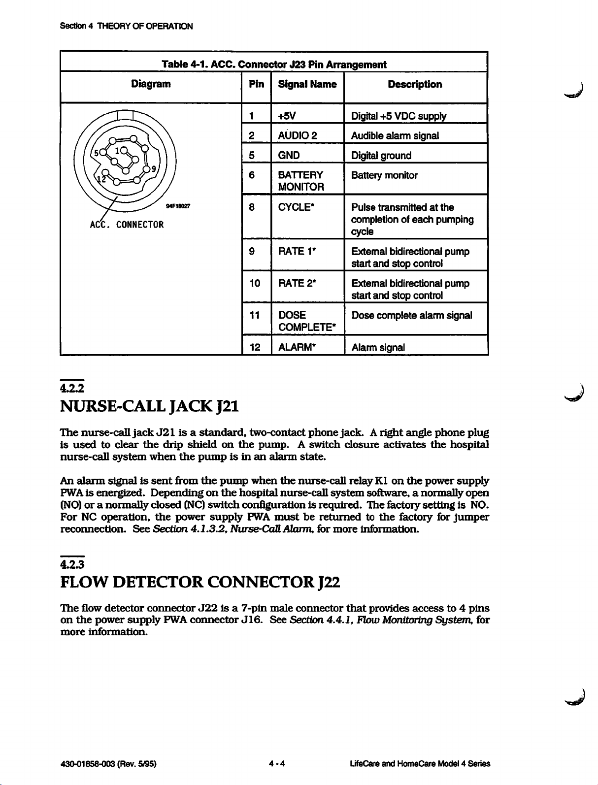
Table
4-1.
ACC.
Connector
J23
Pin
Arrangement
ACC.
Diagram
7^"
~~^S
CONNECTOR
94F18027
Pin
1
2
5
6
8
9
10
11
12
Signal
+5V
AUDIO
GND
BATTERY
MONITOR
CYCLE*
RATET
RATE
DOSE
COMPLETE*
ALARM*
Name
2
2*
Description
Digital +5 VDC
supply
Audible alarm signal
Digitalground
Battery
Pulse
completion of
monitor
transmitted
at
each
cycle
External bidirectional
start
and
stop
control
External bidirectional
start
and
stop
control
Dose
complete alarm signal
Alarm signal
the
pumping
pump
pump
4.2.2
NURSE-CALL
The
nurse-call
is
used
to
nurse-call
An
alarm
PWAisenergized.
(NO)ora
For NC
reconnection.
4.2.3
operation,
FLOW
The
flow
on
the
power
more
information.
jack
clear
the
system
signalissent
normally
See
DETECTOR
detector
connector
supply
JACK
J21isa
drip
when
the
from
J21
standard,
shield
on
pumpisinanalarm
the
pump
Dependingonthe
closed
Section
the
(NC)
power
4.1.3.2,
switch
supply
CONNECTOR
J22isa
PWA
connector
two-contact
the
pump.
A
phone
switch
state.
when
the
nurse-call
hospital
nurse-call
system
configurationisrequired.
PWA
must
be
returnedtothe
Nurse-CaR
Alarm,
for
J22
7-pin
male
connector
J16.
See
Section
4.4.1,
jack.Aright
closure
relayKlon
software,anormally
The
more
information.
that
provides
Flow
angle
activates
the
factory
settingisNO.
factory for
accessto4
Monitoring
phone
the
power
System,
plug
hospital
supply
open
jumper
pins
for
430-01858-003 (Rev. 5/95)
4-4
LifeCare
and
HomeCare
Model4Series
Page 31

4.2.4
4.2
EXTERNAL
INTERFACE
PORTS
>|$g^/
RS-485
Certain
Dataway
Capabilities, for a
capability.
The
RS
and
receive information between a
external
nurse
canbeobtained
limits
A
universal
driver
Section
To
use
modeisaccessed
mode,aDataway
withoutacommand
command,
makes
be
disabled.
remote
DATAWAY
versions
I/O
connector
485
Dataway
host
device
station
can
PWA.
4.5.2,
the
certain
operations.
console.
be
transmitted
asynchronous
Foradetailed
Motor DriverPWA,
Dataway
or
any
that
See
of
the
listofthe
I/O
suchasa
from
the
interface,
from
timerinthe
to
other
continued
Section
I/O
Model 4
JlOl.
connectorisa
Information
pump
to
transmit/receive
the
external
the
pump.
command
4.3.1,
Series
See
Model 4 Series
hospital
through
the
pump
description
and
the
pump
pump
fromaremote
interactive
ModesofOperation,
CONNECTOR
infusion
Table 1-2, Model 4
bidirectional,
maximum
patient
such
as
the
from
the
(UART) device,
of
Section
mustbeoperatinginthe
device
through
producesaDataway
Each
time
communications
pump
infusion
serial
of 31 electrically
data
management
status,
I/O
the
4.5.2.4,
alarm
port.
host
device.
operation
RS-485
the
the
pump
device,
for
JlOl
are
equipped
Series
pumps
data
history,ormalfunction
Information
Ul,ismounted
Dataway
I/O
alarmifone
receives a
the
timerisreset
with
additional
Case
with
interface
connected
systemora
suchasratesordose
of
the
remote
interface.
the
external
information
Dataway
Port
reset
with
an
RS-485
Types
RS-485
usedtotransmit
pumps
and
Dataway
and
computerized
on
the
UART,
mode.
When
minute
The
in
remote
remote
passes
Dataway
This
function
device
on
cannot
local
I/O
an
codes
motor
see
timer
and
Note:
and
number
to
4.2.5
For
Interface Manual,
430-01761
any
external
RS-232
This
technical
4.2.6
20-MA
This
technical
detailed
device.
I/O
PORT
service
I/O
PORT
service
Dataway
UfeCare
-XXX.
manual
manual
This
technical
information,
Model 4 Series Infusion
manual
does
does
shouldberead
not
support
not
support
the
the
see
the
Pumps
before
RS-232
20-mA
Technical Specification Guide
RS-485
connecting
I/O
port.
I/O
port.
Dataway,
the
Dataway
Manual
port
V%r>
Technical
Service
Manual 4 • 5
430-01858-003
(Rev. 5/95)
Page 32

Section4THEORY
4.3
OF
OPERATION
OPERATIONAL
This
section
the
data
4.3.1
MODES
The
Model4Series
1.
2.
3.
4.
5.
6.
Certain
by
the
pump.
describes
retention
function.
OF
OPERATION
infusion
Load/Off
Self
Local
Remote
Battery
System
recharge
test
control
control
discharged
failure
modesofoperation
See
Table4-2, User Controls
the
DESCRIPTION
six
modesofpump
pump
are
has
user
six
controlled.
and
operation,
the
silence/ASK
modesofoperationasfollows:
Other
OperatingModes, for
modesofoperation
additional
function,
are
controlled
information.
and
User
Control
LOAD/LOCK
control
DELIVERY
RATE
set
switch
volume
delivered
CLEAR
switch
DOSE
LIMIT
set
switch
Dose
LIMIT
ON/OFF
CLEAR
switch
Table
Load/
Off
Self
Test
X X X
4-2.
Reset
X
X
D
X
User
Local
Controls
and
ModeofOperation
Control
Operate
X X
Alarm
Operating
Remote
Control
Modes
Battery
Discharged
X X
System
Failure
X
START
switch
RESET
switch
430-01858-003 (Rev. 5/95)
X R X
X X X
4-6
LifeCare
and
HomeCare
Model4Series
Page 33

User
Control
Load/
Off
Table
Self
Test
4-2.
Reset
User
Local
Controls
and
ModeofOperation
Control
Operate
Alarm
Operating
Remote
Control
4.3
Modes
OPERATIONAL
Battery
Discharged
DESCRIPTION
System
Failure
SILENCE
switch
Audible
level
switch
Occlusion
pressure
selector
switch
Set
type
switch
(Microonly)
Note:
during
4.3.1.1
X =
reset
LOAD/OFF
To
enter
the
RECHARGE.
mode:
X X
X X X
X X X
active
state;
time-out
RECHARGE
pump
The
load/off
following
D =
alarm.
X X X
X X X
X
X
active
only
when
MODE
recharge
conditions
mode,
occur
X X
dose
turn
when
X X
control
the
main
the
pumpisin
function
X
X X X
X X
X X
control
is ON; R =
switchtoLOAD/OFF
the
load/off
active
recharge
only
•
Pump
Q
Displays
•
Cassette
Q
Mechanism
•
Nurse-call
Q
Dataisretained
The
following
Q
Failure
Q
Current
•
Dose
•
Audible
Q
Audible
•
Pump
additional
ceases
operation
and
legends
clamps
and
pivot
alarm
as
events
monitor
alarms
limitisenabled
alarm
alarm
retains
occur
is
and
is
is
operating
information)
are
not
illuminated
plunger
shroud
armisraisedtoits
is
disabled
specifiedinSection
when
the
pumpisin
tested
failure
enabled
silenced
or
messages
disabled
or
disabled
and
history
are
highest
4.3.3,
are
data
unlocked
position
Data
the
load/off
cleared
for
for
for
Retention
four
hours
cassette
cassette
recharge
insertion
or
removal
insertionorremoval
Function.
mode:
[see
Section
4.3.3
for
Technical
Service
Manual
4-7
430-01858-003 (Rev. 5/95)
Page 34

Section4THEORY
4.3.1.2
OF
OPERATION
SELF
To
TEST
enter
performs
• All
Q
•
data
been
RAM
Failure
• All
illuminated
Q
Audible
•
Critical
If
any
self
See
Table
successful,
4.3.1.3
LOCAL
MODE
the
pump
the
reached
and
monitor
numeric
data
test
self
test
mode,
following
except
ROM
operationsinself
history
are
test
dataisinitialized if
tested
status
elements, message display elements,
alarm
fails,
is
activated
integrityischecked
the
pump
enters
6-1, Alarm Codes, for a
the
pump
CONTROL
automatically
MODE
turn
the
is
checked
the
system
listoferror
enters
test
main
mode:
failure
the
control
the
codes
local
switchtoLOCK/ON.
four-hour
mode
and
control
data
and
front panel legends
andanerror
descriptions.
mode.
retention
interval
codeisdisplayed.
If
all
The
tests
pump
has
are
are
The
pump
mode,
Controls
If
transmits
does
When
Exit
or
Dataway
system
The
The
front
and
the
pump
status
not
permit
the
codeistransmitted,
the
local
by
sendingacommand
I/O
failure,orwhenadischarged
local
control
reset
successful
pressing
the
Note:Ifthe
dose,
operating
etc.),
parameters
enters
and
Operating
has
remote
control
Connector
state
self
test
[RESET]
pump
the
the
local
rear
panel
Modes).
an
RS-485
messages
control
modebyturning
JlOl).
mode
is
user
has
always
The
user
touchswitch.
must
be
should
and
control
mode
touchswitches
Dataway
and
permits
unless
the
from
REMOTE
the
Exit
from
the
battery
three
activity
the
first
state
can
also
stopped
press
critical
the
data
following a
control
I/O
port
connectedtoa
interrogation
remote
host
legendisilluminated
the
main
control
remote
the
host
local
is detected.
states:
reset,
enteredinthe
switch
during
the
operation
[RESET]
storedinRAM
successful
pump
operations
self
remote
from
the
remote
terminal
transmits
switchtoLOAD/OFF
terminal
control
[see
mode
operating,
local
control
pumptothe
for
touchswitch
that
reset
any
reason
first. [RESET] will
would
test.
[see
host
terminal.
instruction
on
the
Section
occurs
and
alarm.
mode
stateatany
(alarm,
otherwise
In
local
control
Table 4-2, User
terminal,
The
pump
code.
pump.
RECHARGE,
4.2.4,
RS-485
automatically
following a
time
change
save
be
lost
it
at
by
of
The
following
•
The
Q
The
representing
approximately
430-01858-003 (Rev. 5/95) 4 • 8 LifeCare and HomeCare Model 4
conditions
pumping
message
occurinthe
reset
mechanismisstopped
panel
the
1.3
displays
volume
seconds
two
deliveredinmilliliters.
state:
and
the
alternating
cassette
messages:
plungerisretracted
RESET
Each
message
and
is
displayed
a
number
for
Series
Page 35

•
The
Q If
flashes
•
All
The
operating
to
parameters
The
following
•
The
•
The
Q
All
touchswitches
pressure
active
Q
All
The
alarm
the
alarm
main
alarm
alarm
the
alarms
pump
user-set
front
alarm
soundsabeep
reset
state
RESET,
are
stateisthe
setbythe
conditions
mechanism
panel
select
circuits
exceeds
and
prevented
delivery
and
switch,
stateisentered
stateisaccomplished
control
state:
switch
to
onceaminute
five
minutes,
sounds
normal
user.
occurinthe
except
pumping
The
drives
the
operating
the
rateiscontinuously
controls
the
are
active
when
LOAD/OFF
main
and
are
control
the
an
alarm
by
pressing
RECHARGE.
the
pump
alarm
the
reset
timer,
state
during
state
canbeentered
operating
cassetteatthe
state:
indicatedonthe
inhibited
switch.
set
type
except
The
switch
conditionisdetected
the
[RESET]
automatically
cassette,
which
delivery
the
audible
(Micro only)
touchswitch
The
following
4.3
and
the
pump
only
rate
delivery
[RESET]
level
by
conditions
OPERATIONAL
enters
system
operates
from
setbythe
rate
and
switch,
on
the
the
pump.
orbyturning
DESCRIPTION
the
alarm
failure
according
the
reset
user
display
[SILENCE]
the
occlusion
back
panel
Exit
occurinthe
state,
alarms
state.
are
from
the
•
The
rate,orit
•
The
pumping
delivery
mechanism
canbestopped,
rate
display
can
either
depending
flashes
either
L zeros, as requiredby the alarmtype
• If
other
display
•
The
•
The
Q
The
•
The
[SILENCE]
4.3.1.4
REMOTE
The
remote
pump
models
control,
controls
touchswitches.
[PIGGYBACK]
alarm conditions
shows
nurse-call
alarm
[SILENCE]
message
all
alarmsinsequence
system
soundsapattern
touchswitch
display
touchswitchispressed,
CONTROL
control
the
REMOTE legendonthe
canbeused:
mode
equipped
The
touchswitches
with
the
[DOSE
occur
signals
shows
that
is
activated
either
before
MODE
canbeentered
the
RS-485
front panel is
main
control
LIMIT],
(4P only)
[DELIVERY
are
switch,
drive
the
on
the
alarm
the
number
the
existing
an
alarm
the
the
only
Dataway
inactiveinthe
condition
so
that
appropriate
appropriate
from
I/O
and
RATE],
cassetteatthe
type
representing
conditionisreset,
exists
the
alarm
can
alarm
response.
the
local control
port.
When
illuminated
the
[RESET],
remote
and
[LIMIT
keep
vein
open
the
KVO
the
be
silenced
indication,
the
only
[SILENCE],
ON/OFF/CLEAR],
control
or,
mode
and
pumpisin
four front panel
and
mode.
(KVO)
rateorall
message
when
only
the
on
remote
[START]
and
4.3.1.5
BATTERY
The
battery
DISCHARGED
discharged
batterypowerand
Technical
Service
Manual
MODE
mode
the
batterypackbecomesdischarged to
is entered automatically
4 • 9 430-01858-003 (Rev.
when
the
pump
the
point where proper operating
is operating on
5/95)
Page 36

Section4THEORY
OF
OPERATION
power
cannolongerbesupplied.
+7.15VDC.
•
Main
power
Q
History
Q
Pumpisinoperable
Q
Alarm
sounds
• Critical
Exit
from
the
•
Connect
•
Turn
the
pump
mode.
4.3.1.6
automatically
SYSTEM
The
system
mechanical
failure
failure
state
During
supplyisshut
data
memory
data
required
battery
the
pumptoAC
main
FAILURE
modeisentered
or
electrical
and
the
this
modeofoperation,
powerislost
and
all
a
continuous
for
continuing
discharged
(mains)
control
switchtoLOAD/OFF
completesaself
MODE
elements.
peripheral
Battery
discharged voltageisbetween
the
following
conditions
off
communications
tone
pump
and
control
functions
operationiserased
modeisaccomplishedbyperforming
whenever
There
failure
powerorreplace
RECHARGE
test
followinganexit
the
pump
are
two
states
state.
the
battery
and
from
detectsamalfunctioninanyofits
defined
for
+6.85
VDC
occur:
are
suspended
the
following:
pack.
thentoLOCK/ON.
the
this
battery
condition:
discharged
the
and
The
core
Core failure
failureinthe
failure
•
Pump
•
Pump
Q
Nurse-call
•
ASK
Q
Core
Peripheral
conditions:
Q
Malfunctioninthe
•
Mechanical
Q
Failureinnoncritical
•
Short-duration,
•
Any
In
the
stateisentered
microprocessororcore
state:
soundsacontinuous
operation
function
failure
failure
control
peripheral
when
stops
system
error
alarmisactivated
is
inhibited
codeisdisplayed
stateisentered
failure
failure
electric
nonpermanent
overridebythe
failure
state,
the
alarm
when
monitor
circuitry
failure
the
following
failure
circuitry.
monitor
The
tone
(unless
the
microprocessor
circuitry
failureinthe
monitor
conditions
detectsapermanentorlong-duration
following
preventedbythe
conditions
failure)
detects
oneofthe
occurinthe
following
microprocessor
occur:
core
•
Pump
•
VOLUME
Q
Alarm
430-01858-003(Rev. 5/95)
operation
DELTVERED
sounds
stops
display
flashes
MALFUNCT
4-10
LifeCare and HomeCare
Model
4 Series
Page 37

\sf^y
•
Oneormoreofthe
VOLUME
pressed
Exit
from
the
•
Turn
the
Q
Pump
4.3.2
automatically
DELIVERED
simultaneously
system
main
failure
control
failure
display
codes
when
showninTable
two
touchswitches,
6-1,
modeisaccomplishedbyeitherofthe
switch
enters
to
the
LOAD/OFF
battery
RECHARGE
discharged
mode
4.3
OPERATIONAL
Alarm
Codes,
[SILENCE]
following:
and
DESCRIPTION
appear
[RESET],
on
the
are
SILENCE/ASK
The
[SILENCE]
depending
When
alarms
When
the
for
the
touchswitch
causes
the
Function Messages.
displayed
messages
Touchswitches
[SILENCE]
touchswitch
on
the
pump
one
minute,
pump
aloneorsimultaneously
VOLUME
continuously
are
displayedinsequence
FUNCTION
on
stateofthe
isinan
except
is
in
DELIVERED
Duringanocclusion
alarm
the
while
Table
pump.
low
local
the
Power
the
pump
state,
battery,
or
with
displaytodisplay
front
panel
pressing
the
whichissilenced
remote
control
another
alarm,
the
[SILENCE]
touchswitch
the
message
touchswitchispressed,
when
4-3.
ASK
Condition
on
the
touchswitchisreleased.
Function
Messages
performs
for five
modes,
messages
and
OCCLUSION
oneoftwo
touchswitch
silences
minutes.
pressing
foratleast
the
1.25
listedinTable
pertainingtothe
the
remaining
Messages
PRESSURE
SWITCH
MAX
MID
MIN
POSITION
PRES
PRES
PRES
functions,
all
[SILENCE]
seconds
4-3,
ASK
alarm is
applicable
[SILENCE]
[SILENCE]
[SILENCE][CLEAR]
[SILENCE][RESET]
Technical
Service
Manual
Power
on (Microonly)
Occlusion
Absolute
alarm
pressure
Differential
Amplifier saturation
Power
Malfunction
on
4-11
pressure
SET
TYPE
SWITCH
TYPE
A
TYPEB
ABS
PRES
DIF
PRES
ABS
PRES
SFTWR
MALALMCODE
430-01858-003 (Rev. 5/95)
REV
Page 38

Section4THEORY
OF
OPERATION
Table
4-3.
ASK
Function
Messages
Touchswitches
[SILENCE][START]
4.3.3
DATA
Critical
touchswitch
Critical
of
dose
of
any
returning
RETENTION
operating
is
pressed
data
includes
function,
other
the
features
main
dataisautomatically
and
all
data
volume
criticaltopump
control
periodisexceeded,orwhen
mode.
History
power
Once
dataisheldinnonvolatile
are
lost,orthe
critical
data
has
pump
been
pumpispoweredonagain.
Condition
Pump
operating
FUNCTION
storedinmemory
the
main
control
requiredtodefine
delivered, delivery rate,
switchtoLOCK/ON.
the
pumpisin
memory
entersamalfunction
erased,
the
switchisturnedtoLOAD/OFF
operation.
either
andisnot
memory
for four
the
modeofoperation,
dose
limit,
dose
The
memory
Critical
the
values
dataiserased
battery
lost
unless
state.
reverttodefault
discharged
Messages
NUMBER
3 BITS = 1 psi (6.9 kPa)
hours
delivered,
hold
AC
OF
BITS
when
the
[RESETI
RECHARGE.
activity
and
state,
the
timeisrestored
when
the
four-hour
modeorthe
(mains)
values,
and
failure
battery
when
state
state
by
the
4.4
MONITORS
Monitors
system,
systems
4.4.1
FLOW
Refer
Interconnect
Micro
sensor),
the
The
voltage
power
usedasan
data
to
4/MDL
motor
flow
supply
bus
and
detectorsinthe
the
pressure
and
circuitry
MONITORING
Figure
Schematic,
4, International
the
drop
driver
detector
pulse
through
PWA.
inputtothe
and
usedasinputtothe
9-2,
signal
PWA.
clips
The
AND
Model4Series
measuring
are
describedinthe
System
processoronthe
onto
the
J22
outputofthe
motor
system,
Interconnect Schematic, Model 4P; Figure 9-3,
Micro
The
the
drip
flow
driver
DETECTORS
infusion
and
the
following
SYSTEM
4/MDL
flow monitoring
detector
PWA,
microprocessoronthe
4; or
power
chamberofthe
connectortothe
drop
detector
whereitis
pump
malfunction
sections.
Figure
system
supply
circuitryonthe
convertedtodata
consistofthe
detection
9-4,
Interconnect
flow
monitoring
circuitry.
Schematic,
consistsofa flow detector (drop
PWA,
and
associated circuitry
administration
drop
microprocessor
set
detector
power
for
and
provides a
circuitryonthe
supply
the
system
unit
(MPU) PWA.
These
System
on
PWA
I/O
is
The
flow
monitoring
fallinginthe
or
other
430-01858-003 (Rev. 5/95)
drip
flow
interruptions.
chamber
system
checks
and
for a correspondence
the
numberofpump
4-12
between
cyclestodetect
LifeCare and HomeCare Model 4
the
numberofdrops
fluid
supply
depletion
Series
Page 39

\^^y
In
the
Micro
made.
[SILENCE]
This
pump,
selection
touchswitch
the
flow
may
for
detector
be
read
more
than
also
on
checks
the
1.25
which
VOLUME
seconds.
4.4
set
type
switch
DELIVERED
MONITORS
selection
display
AND
by
DETECTORS
has
holding
been
the
Note:
andisan
Series).
4.4.1.1
The
flow
detectorisrequired
optional
accessory
for
for
others
some
versionsofthe
[see Table 1-3, Series Specific Features - Model 4
FLOWDETECTOR
RefertoFigure 4-1, Flow Detector Schematic Diagram.
drops
falling
Ql
through
(not
illustrated).
that
clipstothe
Diodes
through
wiring
phototransistors.
infrared
signal,SNSROUT,
Drop
Signal
within
the
Q3; two diodes, DS1
All
componentsofthe
drip
chamber.
DS1
and
DS2
Q3.
The
resulting
board
(PWB)
and
Whenadrop
energyisreduced,
whichistransferredtothe
Processor).
drip
chamber.
emit
narrow
currents
represent
resultingina
The
flow
and
DS2;
and
flow
detector
beamsofinfrared
are
summedatthe
the
total
infrared
falls
through
corresponding
detector
infrared
reside
the
dropsignal
Model4Series
The
flow
detector
consistsofthree
and
limited
withinapolycarbonate
light
acceptance
toward
outputofthe
energy
infrared
emitted
beam,
current
reductioninthe
processor
infusion
optically
pumps
senses
phototransistors,
angle
filters
housing
phototransistors
photo
from
the
sensor
the
diodestothe
total
amount
Ql
printed
of
output
(refertoSection 4.4.1.2,
Technical Service Manual
4-13
430-01858-003 (Rev. 5/95)
Page 40

Section4THEORY
OF
OPERATION
!PHOTO SENSOR PWB
CI
0.001
uF
PHOTO
2
(MATCHED)
EMITTER
TIL31
PWB
RED
WHT
Figure 4-1. Flow Detector
Schematic
Diagram
ELECTROSTATIC
SHIELD
X
BLK|_ij^GND"
GRN
|3<SNSR
-p<+5
-|^<LED
P22
OUT
VDC
CATH
94F13005
4.4.1.2
DROP
The
and
interference
SIGNAL
drop signal
rejects
extraneous
(EMI),
PROCESSOR
processor
splashes,
accepts
signals producedbydrops
signals produced
and
condensationon
signalprocessorcircuitryisresidentonthe
components:
amplitude
4.4.13
CURRENT
RefertoFigure9-14,
modulator
by
the
2.38
430-01858-003 (Rev. 5/95)
current
threshold
amplitude
detector.
AMPLITUDE
Power
consistsofU6D,
kHz
clock
signal,
modulator,
MODULATOR
Supply PWASchematic, Micro
and
transistor
DSLDCK. DSLDCKisbufferedbyU6D
fallinginthe
by
external light sources, electromagnetic
the
power
wallsofthe
supply
PWA
synchronous
drip chamber.
and
consistsofthe
demodulator,
4/Model4.The
Q3.
The
current
amplitude
drip
current
modulatorisdriven
priortoturning
4-14
LifeCare
and
HomeCare
chamber
The
drop
following
and
drop
amplitude
on
Model4Series
Page 41

4.4
MONITORS
AND
DETECTORS
transistor
through
return
LED
percent
for
phototransistors
abilityofthe
4.4.1.4
SYNCHRONOUS
RefertoFigure 9-14,
demodulator
R18,
associated
DEMCLK
DSLDCK
is
delayedbyabout
active, flow
Q3
resistor
lineasthe
CATH
duty
provides
cycle.
systemtoreject
consistsofa
integrated
components.
clocks,
hasa25
detector
without
R12
signal,
circuit
which
percent
loading
the
priortobeing
LED
CATH (refer to Figure
peak
currents
When
Ql
transistor
through
extraneous
DEMODULATOR
Power
Supply PWA Schematic, Micro
bandpass
(IC)
U3A,
The
synchronous
are
both
duty
53
milliseconds
diodes
DSl
clock
line.
transferredtothe
of
approximately
Q3isoff,
Q3 to reduce gain
infrared
filter
that
holding
2.38
cycle
and
capacitor C3,
kHz
while
(ms)
with
DS2
are
Figure 4-1, Flow DetectorSchematic Diagram).
is
closed.
approximately53ms
at
pin2or
capacitor
With
pin10of
C3.
this
clock
before
U3A, allowing
phasing, flow detector diodes
the
photo
sensor
SNSR
OUTtoreach
The
output
4-1,
photo
Flow
100
of
transistor
detector
Detector
milliamperes
resistorRl1
non
linearity,
light.
4/Model
includes
demodulator
signals
DEMCLK
capacitors
and
buffer
is
that
differinphase
hasa12.5
driven
respecttoDSLDCK.
enabled
Whenever
PWA
and
pin4of
DEMCLKisactive,
DSl
and
outputatP22-3
peak
provides
amplifier
percent
Whenever
DS2
(SNSR
value
before
Q3isconditioned
diodes
Schematic
DSl
(mA)
Diagram).
witha25
a low-level
which
4.
C6
enhances
The
synchronous
and
C8,
U1A
by
the
DSLDCK
and
duty
duty
cycle
DSLDCK
U3Aisopen
pin1of
are
turned
OUT)issampled
being
and
DS2
current
resistor
with
cycle.
that
(refer to
U3A
on
fully
stored
the
its
and
is
in
4.4.1.5
DROP
AMPLITUDE
RefertoFigure 9-14,
threshold
and
associated
reflections
80
millivolts
Resistors
and
an
integrator
for
the
is
rejected.
Upon
microprocessor
the
microprocessor.
approximately
splashes
4.4.1.6
detector
and
Rl,
the
pulse-width
signaltobe
acceptance
from
components.
splashes
(mV)
that
R2,
and
whose
accepted.
thatadrop
128
the
main
THRESHOLD
Power
provides
Supply PWASchematic, Micro
pulse-width
The
and
accepts
exceed3ms.
R15
formareference
discriminator
output
voltage
Any
ofasignal,
has
The
microprocessor
ms.
DRPAK*
drop
from
drop
U1D.
must
signal
drop
been
resets
setting
discrimination
amplitude
signals
withaduration
voltage
Diode
exceed
thatisless
latch
detected.
acknowledges
U6A.
The
U6A
again
DETECTOR
4/Model4.The
and
threshold
divider
CR1,
2.54
detector
resistor
VDC
for
(the
thanorequaltothe
U6A
outputs
The
DROP
lineissampled
DROPbyissuing
128
ms
pulse
and
being
drop
amplitude
consistsofU1C,
rejects
above
both
R3,
the
the
and
threshold
capacitor
reference
2.54
DROP
to
U1D,
short-duration
comparator
voltageofU1D)
VDC
indicate
every5ms
DRPAK* for
widthofDRPAK*
countedaslegitimate
U6A,
value
of
U1C
CI
form
reference
to
the
by
prevents
drops.
^Hisi/
FLOW
Refer
detected
connected,
Technical
DETECTOR
PRESENCE
to Figure 4-1, FlowDetectorSchematic
by
then
Service
measuring
the
Manual
the
voltage
LED
levelofLED CATH
cathode
DETECTION
Diagram
(LED CATH)
equals+5VDC
4-15
The
presenceofthe
voltage
level. If
minus
flow
the
flow
the
combined
430-01858-003
detector
detector
voltage
(Rev. 5/95)
is
is
Page 42

Section4THEORY
OF
OPERATION
dropofDSl
CATHisapproximately0VDC.
The
voltage levelofLED CATH is
located
4/Model
CATH is greater
levelofLED
4.4.1.7
FLOW
The
microprocessor
the
number
expects
depends
typeByields
position,
numberofdrops.
of
drops.
a
countof12, or
drops
exceeds
cycles
flow,
the
either
of
flow condition,
the
flow
and
on
the
DS2. If
motor
the
driver
4 or Figure9-10, MotorDriver PWASchematic, Series 4). If
than
1VDC,
CATHisless
than1VDC,
ALGORITHM
U3onthe
of
one
upon
the
The
exceeds
pump
alarm.
drops
1/15
the
one
MPU
drop
the
the
stops.
detectedinthe
ml
drop
per
set
type:
set
drop
per
pump
divides
For
and
when
the
set
typeB,the
cycle
the
pumpisstopped.
numberofpump
numberofdropsbymore
For
low
the
alarmissounded,
flow detector is
measuredbyU3,
PWA
(refer to Figure 9-9, Motor Driver PWA Schematic, Micro
then
the
flow detector is
MPU PWA
drip
pump
cycle. For
typeAyields
cycle (15
actual
counters
number
effective
are
cyclesbymore
flow,
the
not
connected,
then
the
flow
retains
chamber.
countofthe
the
four
drops
drops/ml).Ifthe
of
drops
numberofdrops
resettozero
If,
than
four, a flow
pump
cyclestothe
and
the
then
the
analog-to-digital (A/D)
assumedtobe
detectorisassumed
numberofpump
For
Models
Micro,
per
the
numberofdrops
pump
set
by
fourtoascertain
equals
when
eitherofthe
during
the
than
four, orifthe
countto12,
alarmisgenerated.
KVO
preset
message
display
the
voltage levelofLED
the
voltage levelofLED
present;ifthe
to
be
4, 4P,
and
cycle (60
type
switchisin
the
counters
4H,
drops/ml);
actual
the
numberofpump
minimum
indicates
converter
voltage
absent.
cycles
the
expected
an
effective
number
reaches
number
For
rate. For
the
nature
and
MPU
the
high
set
A
of
For
the
drops
assures
drops
the
[START]
check
Micro, a flow
are
detected
that
the
detected.
touchswitch
cassette
alarmissoundedifless
The
alarm
during
numberofdrops
also
any
one
occursifthe
pump
expected for
numberofdropsiscounted
has
been
pressed.
than
cycle. In
dropisexpected;analarmissoundedifmore
4.4.2
PRESSURE
The
pressure
The
pressure
sensor.
MEASURING
measuring
measuring
system
system
SYSTEM
measures
consistsofthe
pressure
set
type
switchisin
addition,
the
set
type
correspondstothe
during
For
three
than
the
first
set
type
A, four
drops are detected. For
two
drops
within
pressure
the
sensor
theAposition
the
Micro
complete
drops
are
detected.
cassette
PWA
and
microprocessor
number
pump
and
and
cycle
are
expected;
set
typeB,one
distal
the
tubing.
pressure
no
of
after
a
430-01858-003 (Rev. 5/95)
4-16
UfeCare and HomeCare Model 4
Series
Page 43

4.4.2.1
PRESSURE
The
pressure
in
the
cassette
fluid
through
tubing.
differential
pressures
exceeded,
MicroprocessorU3on
an
SENSOR
sensor
plunger
the
cassette
pressure
encountered
occlusion
PWA
PWA
measures
arm.
The
strainisproportionaltothe
outlet
(difference
during
alarmisgenerated
valve,
the
MPU PWA
between
delivery).
(-004
the
AND
pressure
and
therefore
monitors
the
pressure
When
and
HIGHER)
within
the
absolute
pump
4.4
MONITORS
the
cassettebysensing
force
requiredtomove
reflects
both
requiredtoinitiate
operation
the
the
absolute
differential
ceases.
pressureinthe
AND
DETECTORS
pressure
delivery
pressure
the
strain
distal
and
limit
the
the
and
is
Pressure
electrical
gauge
RefertoFigure 9-5,
and
PWA
andRlbalance
Resistor
7
hertz
output
pressure
and
differential
4A2.2
PRESSURE
The
mounted
of
the
sensor
the
temperature
sensingisaccomplished
resistanceofthe
connectstothe
+STROUT,
stable
R2
(Hz) for
to
hold
the
amplifier,
-STROUT
sets
noise
the
desired level.
filter
on
circuitry
output.
SENSOR
pressure
pressure
PWA formanactive
cassette
measuring
onabeam
sensor
pivot
compensation.
strain
pressure
Pressure
full-bridge
Ul.
CapacitorsCIand
and
the
gain
and,incombination
suppression.
the
power
for
stable
system
attachedtothe
PWA.
arm
and
senses
with
a full-bridge
gaugeis350
sensor
Sensor
strain
+STROUT priortoinputatUl,
The
supply
amplifier,
PWA
PWA
PWA Schematic, Micro
gauge
ResistorsR5andR6attenuate
PRESSURE.SIGNAL
PWA. Capacitors
Ul.
(-003
usesadual
endofthe
The
strain gauge
halfofthe
the
bridge
strain
ohms
through
outputs,
C2 filter
with
Resistor
AND
LOWER)
element,
cassette
rosette
circuit
duetopivot
strain
are
gauge
after
activationby+5AN.
a four-wire
transferredtothe
high
capacitor
output
C4
R4
and
90
plunger
and
The
straingauge RM is aligned along
arm
mountedtoa
jacketed
4/Model
frequency
and
capacitor
degree,
4 (Sheet 2).
pressure
noise.
pins13and
C8,
rolls
the
the
PRESSURE_SIGNAL
is
directedtoa two-pole
C5
are
partofthe
C3 are
strain
pivot
arm
and
componentsofthe
flexure.
Resistor
cable.
Resistors
5, respectively.
bandwidth
gauge rosette
R90
beam.
The
The
strain
-STROUT
sensor
R3
sample
partofthe
components
pressure
provides
at
Referto Figure 9-5, Pressure SensorPWASchematic, Micro
Ul
and
U2
and
associated components residing on
gain, chopper-stabilized amplifier for
Resistor R4 provides offset
The
outputofthe
U12B
amplification
converter.
is
4.4.2.3
and
associated
U1onthe
suppliedtoUl
OCCLUSION
for
pressure
components
the
pressure
pressure
by
U4
ALARM
Pressureismeasuredbytaking
stroke
endofthe
and
the
strainatthe
intake
phaseofthe
adjustment
sensor
on
the
topofthe
PWA is transferred to
form a
signal
sensor
power
ALGORITHM
the
difference
pump
the
low-level signal generatedbythe
and resistor R5 controls sensitivity adjustment.
low-pass
beforeitis
PWA
requires-5VDCaswellas+5
supply
PWA.
between
pump
cycle).
The
the
pressure
appliedtothe
stroke
differenceisduetothe
4/Model
pressure
U12Bonthe
the
strainatthe
(that
is,atthe
filter
4 (Sheet 1). Amplifiers
sensor
that
motor
beginning
the rubber diaphragm as the plunger moves up and down, and the
Technical
Service
Manual
4-17
430-01858-003
PWA form a high
strain gauge.
power
provides additional
bottomofthe
supply
driver PWA
VDC.
The-5VDC
PWA.
A/D
pump
andatthe
passive
force
stretch
caused by
(Rev.
5/95)
of
Page 44

Section4THEORY
OF
OPERATION
backpressure.
square
inch
[SILENCE]
nominal
stretch
value
and
outputtogive
duetocassette
The
difference is displayed in
gauge (psig))
touchswitches
for
the
differenceis62
cassette
the
absolute
and
mechanism
outlet
(34.5 kilopascals (kPa)) for
The
pressure
been
pressedisstoredasthe
from
the
differential
The
differential
back
panel.
the
[SILENCE]
differential
(55.2 ±
pressureisgreater
pressureisgreater
displayed
differential
touchswitch
measured
pressures
pressure.
The
pressure
20.7
kPa),
and
pressure)
for
measured
pressure
setting
touchswitch
limit
and
than
than
an
occlusion
canbecalledupto
more
than
during
MIN
in
the
VOLUME DELIVERED displayifthe
are
pressed
simultaneously
bitsat0.0
valve
opening
pressure
pressure)
reading.
differences,
absolute
the
pressure
second
intake
reference pressure.
during
the
third
limitisselectedbythe
may
be
read
from
the
for longer
than
to 12 ±4 psig(82.8 ±
pressureis4 ±2
the
limit
15 ± 5
alarm
setbythe
psig
(103.5±34.5
will
occlusion
result
the
1.25
seconds.
bits
(approximately three
while
the
psig (due
onlytothe
andissubtracted
The
reading
resultinginan
hasagreat
overall
readings.
phase
and
occlusion
after
This
reference
subsequent
pressure
the
VOLUME DELIVERED
1.25
seconds.
27.6
kPa), MID
psig
(27.6 ±
kPa),
The
typeofocclusion
message
pressure
displaybypressing
pressure
13.8
switch,orif
an
OCCLUSION
bits
per
pound
[START]
pump
is operating.
passive
from
diaphragm
the
amplifier
dealofvariability
toleranceof± 5
[START]
touchswitch
pressureissubtracted
pump
cycles to give
switch
locatedonthe
displaybypressing
MAX
pressure
sets
setsitto 8 ±3
kPa). If
the
message
alarm
differential
the
measured
(absolute
the
[SILENCE]
will
per
and
The
psig
has
the
the
psig
be
or
An
absolute
0.175
LOCK/ON,orduring
4.4.3
VDC
MALFUNCTION
The
malfunction
stagesofpump
LOCK/ONorLOAD/OFF
Alarm
by
pressing
malfunction
RAM
for
4.4.3.1
INTERNAL
When
the
occlusion
or
greater
detection
activity:
and
failure
the
alarmissounding.
use
with
RAM
main
control
alarm
than
pumping.
during
RECHARGE,
codes
are
[SILENCE]
the
RS-485
TEST
switchisturnedtoLOCK/ON,
occursifthe
4.4
VDC
either
DETECTION
circuitry
listedinTable
and
Dataway
the
[RESET]
Alarm
detects
self
and
I/O
and
RAMisexercisedbywritingacheckerboard
and
reading
is
foundtobe
the
inverseofthat
defective,amalfunction
pattern
to verify
alarm
pressure
when
CIRCUITRY
hardware
test
when
during
6-1,
Alarm
touchswitches
failure
port.
patterntoall
that
occurs.
amplifier
the
main
output
control
malfunctionsatany
the
main
control
normal
operation.
Codes.
These
simultaneously
codes
every
are
also
every
byteinthe
bits,
readingitback,
bit
is fully functional. If
remains
less
switchisturned
oneofthree
switchisrotated
codes
are
called
while
storedinthe
microprocessor
then
than
to
to
up
the
external
writing
any
bit
430-01858-003 (Rev. 5/95)
4-18
LifeCare
and
HomeCare
Model
4 Series
Page 45

4.4.3.2
ROM
After
and
do
4.4.3.3
POWER-UP
Refer
Micro
TEST
the
RAM
test,acomplex
compared
not
match,
againstachecksum
the
ROMisdefective,
TEST
to
Figure
9-7,
MPU
4/Model4.ResistorR2and
whichisreadatpin4of
after
pump
four-hour
(e.g.,
sets
critical
ifitis
initializationtodistinguish
data
retention
the
delivery
dataisleftasis.
still
low,amalfunction
mathematical
PWA
Schematic,
capacitor C8 form
microprocessor
period. If
rate,
turns
the
Following
alarm
checksumisgenerated
storedinROM.Ifthe
andamalfunction
Series4or
the
the
the
occurs.
buffer
between
PWR UP
dose
external
U8.
The
a cold
lineislow, U8
limit
off, etc.).Ifthe
RAM
test,
4.4
MONITORS
using
calculated
alarm
Figure
power-up
and
occurs.
9-8,
(PWRUP)
MPU
stored
PWA
PWRUPlineistested
powerup
andarestart
initializes
PWR
UP
lineishigh,
the
PWRUPlineistested
AND
DETECTORS
all
ROM
checksums
Schematic,
detector
immediately
during
all critical
bytes,
signal
the
data
the
again;
Ni^s/
4.4.3.4
HARDWARE
The
hardware
microprocessorbycomparinga25-Hz
fixed
frequency
significantly
nurse-call
relay,
RefertoFigure 9-13,
comparison,
25-Hz
(the
main
24.4-Hz
(counterAequals
outputatU15
one
counter
the
other
counter
both
inputsofU17B
theJandKinputs
The
outputofU17D
the
process.
If
one
counter
the
time
the
WATCHDOG
watchdog
signal
different,
and
on
derived
the
attemptstorestart
Display
the
four-bit
program
binary
signal
signal)orcounter
Q3A
and
to go low,
(either
(either
other
reaches
are
counter
and
counterAor
the
are
high,
low
producesnochangeinthe
not
only
counterAor
the
display
from
the
hardware
driver
signal
generatedbythe
reference oscillator
watchdog
the
microprocessor.
DriverPWA Schematic,
counter
watchdog
B (WDSTB)
Q4A;
allowing
counterB)has
count
its
outputislow.
clocks
reaches
U16
receives
strobe
(WDSTB)atpin
reaches
counterBequals
the
outputofU17Dtogo
of
12,
its
the
flip-flop,
counterB)has
the
countof12,
PWA
monitors
main
Yl.Ifthe
sounds
Series
the
Q3B
reachedatleast
respective
Clocking
state,
but
also
not
its
a
4. In
the
24.4-Hz
countof12,
and
Q4
the
J-K
and
clears
reachedatleast
respective
the
functionality
program
two
continuous
performing
signalatpin1and
9.
When
either
its
respective
Q4B)ishigh;
high
and
the
countof8bythe
output
the
the
willbehigh.
flip-flop
flip-flop
U16
Q4
output
U18B
countertorestart
the
of
witha24.4
frequencies
tone,
the
sets
frequency
counter
output
causing
clock
U18B. If
while
remains
countof8
willbelow,
the
Hz
are
the
the
the
time
Since
both
reset
by
resulting in the outputofU17Bbeing hi^tiand settingthe J-K flip-flop U18Bto cause the
reset
(RST)
linetogo
through
sounds
microprocessor
capacitor
the
alarm
monitors
MALFUNCTION
in
the
set
state
untilitis
switch
from
LOAD/OFF
oscillatorisoperating
andisoperatingatthe
high
and
CIO,
keeps
tone
continuously,
the
messageifthe
reset
RECHARGEtoLOCK/ON.
properly,
proper
the
RST
linetogo low.
the
motor
RST
RST
by
the
rate,
power
supply
and
activates
line
through
the
lineisfoundtobe
an
INIT
pulse
generated
This
microprocessorissuccessfully
andifeither
fails,
This
resets
disabledtoprevent
the
nurse-call
I/O
input
high.
process
buffer
The
by
U18B
turning
assures
passing
the
motor
willbedisabled.
the
microprocessor
further
alarm.
U8
and
flashes
flip-flop
the
main
that
the
the
sanity
pumping,
The
the
remains
control
reference
check
A
Technical Service Manual
4-19
430-01858-003 (Rev. 5/95)
Page 46

Section4THEORY
4.4.3.5
OF
OPERATION
HARDWARE
WATCHDOG
TEST
Refer to Figure9-13, Display Driver PWASchematic, Series 4.
tested
are performed, one
toggled to
on
2.5
the
the
the
watchdog
malfunctionifthe
performsnotest,
4.43.6
SOFTWARE
If
hardware
pump
watchdogisan
the
from RAM
passages
alarm
each
time
the
each
cause
the
display
seconds,
a hardware watchdog malfunction,
driver PWA
the
microprocessor
malfunction is stored
data
next
retention
time
malfunction.
period (four hours)
the
pumpisturned
lineislow.
but
WATCHDOG
the
microprocessor
watchdogatthe
at
an
incorrect rate,
independent
motor
flag.
and
The
software
predicts
differs from
sounds.
main
control
time
and
Again,
preparestorepeat
successfully
proper
the
the
detected occurrencesbymore
switchisturnedtoLOAD/OFF
the
pumpisturned
and
subsequent
checks
displayed
off,
the
The
the
software
subroutine,
watchdog
to see
the
has
not
WDSTBisheld
microprocessor
third
time
the
passes
rate,
the
butasoftware
watchdog
andisnot
also performs calculationsonthe
passageofthe
off. During
which
resetting
that
the
next
time
elapsed. If
of
RST
the
the
low long
monitors
the
pumpisturned
cycle
the
next
timeitis
hardware watchdog
malfunction
detects
affectedbythe
motor flag. If
than
The
hardware watchdog is
RECHARGE.
the
first test, WDSTB is
resultsinthe
the
microprocessor.
line
has
been
pump
is activated, as long as
high
frequency
Two
settingofU18B
After
set
high;ifnot,
test
is passed,
enoughtocauseahardware
the
RST
line
and
stores
off,
the
microprocessor
the
the
20
turned
test
causes
condition.
presenceorabsence
predicted
percent, a
off.
and
strobes
the
motor
The
software
rate
information
numberofflag
malfunction
tests
a
the
to
of
4.4.3.7
MICROPROCESSOR
The
microprocessor
outputs
microprocessor
accumulator
is
reasonable
testisnot
malfunction
and
the
that
passed,
condition a
nurse-call
and
certainty
sanity
the
microprocessor
sanity
index
WDSTBisnot
alarm
4.5
ELECTRONICS
OF
The
major
OPERATION
electronics
functions:
Q
Controls
subsystemofthe
delivery
SANITY
check
check
register,
that
consistsofa
must
includes
and
RAM
the
microprocessorisfunctional,
sent,
continuous
sounds.
tone
SUBSYSTEM
Model 4 Series
rateassetbythe
CHECK
setofinstructions
perform
many
causing
of
locations.Ifthe
a hardware
sounds,
front
panel
without
the
commonly
the
motor
infusion
controls
with
known
error
sanity
and
watchdog
power
every
used
checkispassed,
WDSTBissent.Ifthe
25
instructions,
malfunction.Inthis
supplyisshut
PRINCIPLES
pump
performs
inputs
ms.
the
and
The
the
there
down,
following
430-01858-003 (Rev. 5/95) 4 - 20 LifeCare and HomeCare Model 4
Series
Page 47

•
Provides
•
Processes
•
Displays
•
Provides
•
Allows
•
Furnishes
monitoring
I/O
• Provides
and
The
electronics
PWAs
and
•
MPU
Q
Motor
•
Display
Q
Display
•
Power
•
Pressure
Q
Motherboard
Q
Current
dose
limit
signals
rate,
dose,
audible
capabilitytouse
communications
and/or
port
internal
safety
subsystemofthe
associated
PWA
driver
supply
PWA
driver
sensor
boost
PWA
PWA
PWA
PWA
charger
capability
from
the
flow
volume,
alarm,
indicationofany
the
hospital
between
controlofpump
monitors
and
self-checkingfunctionstomonitor
Model 4 Series
interconnect
PWA
PWA
cabling:
4.5
ELECTRONICS
detector
and
and
status
the
information
alarmormalfunction
nurse-call
pump
and
system
host
operationifthe
infusion
SUBSYSTEM
pressure
PRINCIPLES
sensor
condition
asanalarm
computerorterminal
pumpisequipped
pump
consistsofthe
OF
OPERATION
indicator
for
withaDataway
pump
performance
following
remote
c
The
operationofthe
PWA
(-004
and
Higher),
the
motherboard
operation
(see
functionsofthe
since
they
areanintegral
principlesofoperation
the
alarm
4.5.1
MPU
circuitry,
PWA
RefertoFigure
Micro
4/Model4.The
microprocessor
pump
components
MPU PWA
circuitry,
4.5.1.1
and
PWA
Figure
power
9-7,
circuitry
consists
I/O
ports.
through
MICROPROCESSOR
pressure
and
has
9-6,
supply
for
sensor
Section
no
active
Motherboard
PWA
partofthe
the
remainderofthe
PWAisdescribedinSection
4.4.2.2,
Pressure
components,itis
PWA
Schematic,
are
describedinSection
monitoring
and
PWAs,aswellasthe
follow.
MPU PWA Schematic,
Series4or
MPU PWA provides microprocessor
of
control,
memory
the
connector
circuitry,
MPU
P5. In
PWA
exchanges
additiontothe
memory
CIRCUITRY
Sensor
not
detection
Figure
control
data,
latch
4.4.2.1,
PWA
(-003
and
coveredinthe
Series
4.4,
4).
In
Monitors
functionsofthe
control
9-8,
MPU PWA
for
the
control,
microprocessor
circuitry,
memory
Pressure
Lower).
principles
addition,
and
pump.
switches
Schematic,
pump.
and
status
circuitry,
Sensor
Since
of
some
Detectors,
The
and
Through
with
the
protector
nIIUs/
RefertoFigure
Micro
oscillator
Technical Service Manual
4/Model
Yl.
9-7,
4.
Microprocessor
MPU
PWA
The
microprocessor
Schematic,
U3isa
Series4or
circuitry
complementary
4-21
Figure
consists
metal
9-8,
MPU
of
microprocessor
oxide
semiconductor
PWA
Schematic,
U3
and
(CMOS)
430-01858-003 (Rev. 5/95)
Page 48

Section4THEORY
IC
that
provides central processing for
OF
bidirectional ports
bus
(BO
through
OPERATION
(PAO
throughPA07 and
B7),anaddress
bus
the
pump. U3 contains 112
PBO
throughPB07), a multiplexed address data
(A8
through
A12), a timer,
bytesofRAM,two 8-bit
and
oscillator
Yl.
OscillatorYlconsistsofthe
and
C4.
Ylisinternally dividedbyfive to provide a 1 MHz
4.5.1.2
MEMORY
CIRCUITRY
5 megahertz
(MHz)
crystal
Y2,
resistor
system
Rl,
and
frequency.
capacitors C3
Refer to Figure 9-7, MPU PWA Schematic, Series 4 or Figure 9-8, MPUPWA Schematic,
Micro
4/Model
2KX
8 IC. U5ismapped
by
the
voltage
operation.
disabledbythe
batteries
VMEM
ROMU9isan8K
U2AandUlA.
4.5.1.3
provides
MEMORY
After
remain
4.
The
memory
the
four
memory
into
(VMEM) signal. VMEM is a 5 VDC signal during normal
hour
circuitry
memory
memory
consistsofRAM
addresses
0(i6) to 3FF(i6)byICUl1A. U5 is
retention period
U5
has
and
passed
MCU PWA,VMEM remains activeatapproximately
charged or AC (mains) power is available.
non-volatile
x 8 IC. U9ismapped
LATCH
retentionofalarm
CIRCUITRY
into
and
memory
malfunction
addresses
The
ROM
U9.
RAM
U5isa
powered
pump
and
system
2.3
VDC as long as
uninterrupted
codes.
from 400(16)to1FFF(16)
power
activity
the
by
is
of
Memory
address-then-data
RAM or ROM,
B7,
byte
multiplexed,
busisthen
or
ROMisenabled,
4.5.1.4
MEMORY
Memory
non-I/O
microprocessor
and
into
latch
the
the
address
memory
the
prepared
PROTECTOR
protector
pumps).
is
low
complete
powerup
RAMCSline (U5-18)
to
the
5
VDC
4.5.1.5
I/O
RAM.
power
PORTS
At
the
decays
providedbyIC
bus
configuration.
order
address
strobe
latch
for
depending
circuitryisprovided
UllB
high
(AS) line (U3-6) goes lowtolatch
U4.
Since
memory
the
read or write operation.
on
and
UllC
and
powerdown.
through
U4.
byte
the
address
the
address
CIRCUITRY
prevent
ICsUlIC
MicroprocessorU3hasamultiplexed
Duringamicroprocessor
appearsonthe
high
order
address
is availableinparallel.
decodingbyICs U2A, U1A,
by
ICs
UllB
the
U5 RAM from accepting data during
During
andUlIB,
powerup,
microprocessor
When
and
and
initiationofpowerdown, REGON goes low,
and
the
microcomputer
shuts
down.
read or
write
busasBO
the
BO
bits
(A8
through
through
The
B7
A12) are
microprocessor
theDSline goes high,
andUl1A.
UllC
(also
PWR
UPislow, forcing
preventing
holding
U2C
any
and
data
CS
highasthe
cycle from
through
address
not
the
RAM
U2D
for
the
transfer
^^
Communication
I/O
ports:
system
430-01858-003 (Rev. 5/95) 4 - 22 LifeCare and HomeCare Model 4
components
the
between
interrupt
with
the
MPU PWA
request
which
(IRQ*)
the
MPU
and
line,
the
and
PWA
pump
the
must
is provided
reset
(RST) line.
communicate
through
Since
cannot
two
eight-bit
manyofthe
dosoat
the
Series
Page 49

1
MHz
microprocessor
through
The
IOD7
The
configured
and
the
portBlines
are
configuredasan
portAlines
for
IOA5
enables
strobetothe
control
microprocessor.
4.5.2
switch
two
eight-bit
are
are
output
the
hardware
and
frequency,
ports.
designated
eight-bit,
designated
only.
IOAO
microprocessor
watchdog.
the
RST
4.5
separate
input/output
bidirectional
input/output
through
IOA3
address
The
IRQ*
line
is
used
ELECTRONICS
I/O
busses
data
address
form
decoder.
SUBSYSTEM
for
address
(IOD)0through
I/O
data
bus.
(IOA) 0
the
I/O
address
WDSTB
lineisusedtosense
by
the
hardware
PRINCIPLES
and
data
IOD7. IODO
through
bus.
is
the
the
positionofthe
watchdog
OF
OPERATION
are
provided
through
IOA5
IOA4isunused
and
are
microprocessor
main
to
reset
the
MOTOR
RefertoFigure
Driver
an
Dataway
A/D
PWA
Schematic,
converter,
port.
DRIVER
9-9,
Motor Driver PWA Schematic, Micro
andaUART
For
I/O
PWA
Series4.The
whichisonly
addresses,
motor
see
driver
Table
PWA
usedifthe
4-4,
I/O
4/Model4or
consistsofthe
pumpisequipped
Address
Table.
Figure
I/O
address
with
9-10,
decoder,
an
Motor
RS-485
Technical Service Manual 4 - 23 430-01858-003 (Rev. 5/95)
Page 50

Section4THEORY
OF
OPERATION
Table
4-4.
I/O
Address
Table
Address
00
Device
LEDbars
SHIFT
0-1
and
numeric digitaldisplay drivers
REGISTER
LED
bars:
LOCATIONS:
BIT
LEGEND
0-1 Flow detector inoperative
2 Battery operation
3 Low (battery)
4-5 Piggyback (Model 4P)
4-5 Operating (other models)
6-7
For
numeric displays below: BIT SEGMENT
0 a
1 b
2 c
3 d
4 e
5 f
6 g
Remote
control
7 Decimal point
2 RATE, left
ADULT
most
digit 100 10
MICRO
3 next digit 10 1
4 next digit 1 0.1
5 DOSE, left most digit 1000 100
6
7
8
9 DOSE
10
11
next
digit
next
digit
next
digit 1 0.1
LIMIT,
left
most
digit 1000
100
10
100
next digit 100 10
next
digit 10 1
10
12 next digit 1 0.1
13
14
15
RATE
DOSE
dP
dP
dP
1
01
02
430-01858-003 (Rev. 5/95)
Messages/volume-delivered display
A/D
and
shift register clock
Bits
0-5
Bits
6-7
converter
Bits
0-4
ASCII
Unused
multiplexer
unused
Code
5 A/D converter multiplexerleast significant bit (LSB)
6 A/D converter multiplexer
7 A/Dconverter multiplexermost significantbit
Addr 0 (00000000)
Pressure
amplifier
1 (00100000) Battery voltage / 2
2 (01000000) Drop
3 (01100000)
4 (10000000)
5 (10100000) Digit
sensor
Pressure
Segment
check
LED
select
check
voltage
anode
voltage
6 (11000000) +2.5 V reference
7 (11100000) +5 V analog supply
4-24
LifeCare
and
(MSB)
HomeCare
Model4Series
Page 51

Table
4-4.
4.5
ELECTRONICS
I/O
Address
SUBSYSTEM
Table
PRINCIPLES
OF
OPERATION
Address
03
04
05
Device
Motor winding
energizer
Bits 0-3 Phasing (1=winding energized)
Miscellaneous
Bits 0 Drop
outputs
(active high
sensor
LEDcontrol (0=on)
unless
1 Nurse-call (1=on)
2
3
Message
Power
display
supply control (1=on)
clear
4 Motor/cassette interrupter LEDcontrol (0=on)
5 RTS flag (SIO port) (Model 4P only)
5
6 Audible
7
Miscellaneous
Bits 0
1
2 Accessory port
3 Accessory port
4 I/OA1signal
Pressure
Accessory
outputs
Accessory
Accessory
sensor
tone
control (1=on)
port
port
port
400
Pk det.
rate
stroke
rate
dose
dose
kHz
bit 1
bit 2
(CMimit
(0=limit
5 Motor voltage off(0=limit reached)
6 Drop acknowledge bit (0=acknowledge)
7 (Reserved for shift register input)
noted)
(0=clear)
reset
enable
(1=reset)
reached)
reached)
(0=enabled)
06
07
Keyboard buffer number1 (1=key
Bits
0
1
2
3
4
5
6
7
Miscellaneous
Bits
0
1
2
Increase
Decrease
Clear
Silence
Reset
Dose
Increase
Decrease
inputs,
1st
Start
Power
Drop-sensed
volume
limit
buffer
switch
up
rate
rate
on/off/clear
dose
dose
signal
3 Motorflag (interrupter) signal
4
5
6 Micro
Watchdog
Accessory
cassette
reset
port
7 Message-display-full signal
pressed)
limit
limit
signal
stop
bit 1
interruptersignal
n||^/
Technical
Service
Manual
4-25
430-01858-003
(Rev.
5/95)
Page 52

Section4THEORY
OF
OPERATION
Table
4-4.
I/O
Address
Table
Address
08
09
10
Miscellaneous inputs,
Bits 0
1
Digit
Accessory
2 UARTtransmit buffer empty
3
4
UART
Set
1=Set
5 Mode switch ([PIGGYBACK] touchswitch on front panel)
(Model4Ponly)
A/D
UART
Bits 0
6-7
5-7
converter
status
Unused
Unused
output
bits
Date
1 Parity error (PE)
2 Framing error (FE)
3 Overflow error (OE)
4 Transmitter ready (TRE)
5 Transmitter buffer ready (TBRE)
6-7
Unused
Device
2nd
buffer
driver shift registeroutput bit
port
stop
bit 2
reset
bit
type
0=Set
type A (60 drops/ml)
type
B (15 drops/ml)
(Model4Ponly)
(All
other
Models)
received (DR)
^nsT
4.5.2.1
I/O
11-15
11
12
13
14
15
ADDRESS
Unused (Model4Ponly)
UART
UART
receive
transmit
character
character
Display checking multiplexer
Bit
0-2
Bit3unused
Bit
Unused
Unused
segment
4-7
digit driver
driver
check
check
DECODER
RefertoFigure 9-9, Motor Driver PWA Schematic, Micro
Driver
which
lines
The
addresses
U10
devices,
PWA
Schematic,
consists
of
Series4.The
ICs
U8, U9,
IOA0, IOA1, IOA2, IOA3,
four
I/O
address
are
disabled
correspondstoone
listed
in
lines
Table
unless
external
4-4,
and
U10.
and
IOA5
IOAO
through
IOA5isactive
device
I/O
Address
motor
with
driver
These
from
IOA3
which
Table,
PWA
address
the
microprocessor,
define
flow).
Each
the
include
oneof16
I/O
4/Model4or
contains
decoders
the
possible
address
data
bus
the
front
Figure 9-10, Motor
I/O
address
receive
U3,
on
the
the
I/O
five
MPU PWA.
devices.
decodedbyU8,
communicates.
panel
displays
decoder,
address
All
U9,
and
These
and
430-01858-003 (Rev. 5/95)
4-26
LifeCare
and
HomeCare
Mode!4Series
Page 53

4.5
ELECTRONICS
SUBSYSTEM
PRINCIPLES
OF
OPERATION
keyboard,
buffers,
4.5.2.2
INPUT
RefertoFigure
Driver
buffer
supply
is
placed
microprocessor,
4.5.2.3
A/D
RefertoFigure
Driver
is
an
the
A/D
converter
and
miscellaneous
PWA
DATA
Schematic,
BUFFERS
9-9,
Motor
U8isresetatpowerup
PWA,
the
display
on
the
eight-bit
U3,
and
CONVERTER
9-9,
Motor
PWA
Schematic,
eight
channel,
multiplexed-input,
converterisclockedbya
associated
eight-bit
generatedbythe
controlledbyaddress
channels
circuitry.
bidirectional
three
follow:
The
I/O
A2,
and
multiplexer,
input
buffers
Driver
Series
PWA
4.
Data
andisgatedbyA7*. U7
driver PWA,
I/O
data
off-boardtothe
Driver
Series
400
4.
kHz
PWA
The
signal
eight-bit
data
bus.
most
significant
and
output
and
Schematic,
buffer
the
motor
bus
(IOD0-IOD7)
motor
Schematic,
A/D
eight-bit
generated
output
Input
bitsofthe
UART
output
U7isenabled
driver PWA,
driver
converter,
is
connected
channel
status,
three
latches.
Micro
4/Model4or
when
and
U8
input
and
the
and
transmitted
PWA
Micro
4/Model4or
U3orU5
binary
on
the
output
display
to
the
on
selectioniscontrolledbythe
I/O
address
bus.
enableiscontrolledbyaddress
transmit
Figure
A8*isactive
data
from
front
panel.
to
the
Figure
the
motor
converter.
driver
MPU
PWAbyU4
PWA
Conversion
A9.
The
and
receive
9-10,
low.
the
This
MPU
9-10,
driver
The
through
address
timing
eight
Motor
Data
power
data
PWA
Motor
PWA,
A/D
and
the
is
input
1.
Channel0measures
2.
Channel1monitors
pumpisoperatingonbattery
3.
Channel
4.
Channel3monitors
5.
Channel4measures
6.
Channel5measures
7.
Channel6monitors
8.
Channel7monitors
The
A/D
scaled.
the
4.5.2.4
For
converted
RS-485
On
versionsofthe
motor
Table
driver
1-3,
2
determines
converter
uses
example,
outputisexpressed
DATAWAY
Model4Series
PWA
has
Series
Specific
using
pressure.
the
unregulated
ifaflow
the
settingofthe
the
LED
the
LED
the
power
the+5VDC
the+5REF
an
input
PORT
an
interface
Features
DC
power
pack
andifthe
detector
is
connected.
occlusion
anode
cathode
voltagesofthe
supply
voltagesofthe
reference
reference
lineasthe
reference
voltageof2.5
as
10000000(2).
infusion
with
pump
the
RS-485
- Model 4 Series).
battery
supply.
VDC:
that
have
This
supply
packislow.
pressure
numeric
numeric
voltage
voltage
2.5
VDC/5x256
an
Dataway
I/O
voltagetodetermineifthe
select
switch.
and
and
(2.5
VDC
from
which
RS-485
function
port
Dataway
through
utilizes
( U2 for RS-485 receive/transmit functions during remote operation from a
^"^
Onversions of the
port,
the
UARTdeviceonthe
Model4Series
motor
infusion
pump that do not havean
driver PWA is designated U1
and
is configured for serial
bar
displays.
bar
displays.
nominal).
all
inputs
= 128.
JlOl
host
computer.
RS-485
are
Thus,
port,
the
(see
the
UART
Dataway
Technical Service Manual 4 -
27
430-01858-003 (Rev. 5/95)
Page 54

Section4THEORY
OF
OPERATION
data receive/transmit functions through
supported
The
RS-485 station ID
buffer
address
into
U3
high.
downconverter.
determine
The
RS-485
a high-speed differential tri-state
RTSCTL signal,
output
on
the
signal.
onlyactive
When
is
active
The
RS-485
identical to U12,
software,
output
RRI
input
the
RRI
by
software.
bits
U4.
This
buffer
15* (the
when
When
address
enabled, U3 provides a data
the
baud
requesttosend
places
outputofU10,
14 (address 14*
This
downconverter
rate
inputtothe
whichisapplied to
latch
U6.
The
inputs
MPU PWA,
The
operationofU12 is
when
RTSCTLishigh,
high.
the
(pin 25)ofthe
(pin 20)ofthe
signalisconnectedtothe
serial
UART
thus
effecting microprocessor controlofU12bymeansofthe
the
pumpisin
the
RTSB
data
lines (SDA
but
with
Ul
transmits
UAKT, or receives serial data from
UART.
(address
data
(RTS)
bits
representing
pin
9) is active low.
UART
lines
bus/line
the
to U6 are
such
that
a transmitting
line is active high;
and
a different external configuration.
serial
The
TRO signal is connected to
RO
the
power
0-5 and
outputofU10,
translates
Ul.
(RTSA
the
the
address
output
the
and
supply
PWA. These functions are
device address parity bit)
These
pin
to U2
status
RTSB)
bitsonthe
data
10, invertedbyU15) is active
which
of
are
connectedtoU12,
outputs
the
I/O
is
station
data
are
an
transceiver. This device is controlledbythe
DI
inputofU12 from
the
I/O
data
bus
bits
the
RSTA
and
RSTB
mode
as instructedbythe
when
SDB) are connected to U13,
datatothe
RS-485
the
output
0-7
from
05
(pin 15)ofthe
the
microprocessor
outputsofthis
host
RTSCTL is low,
the
whichisfunctionally
When
Dataway port
commanded
via
RS-485 Dataway port via
theDIinput
outputofU13.
input
bus
when
then
latched
eight-stage
ID
bits
which
RTSCTL
device
computer.
RSTA
the
TR03
to U13
not
to
to
is
are
line
by
the
and
The
operationofU13iscontrolledbythe
outputofUl
on
the
determines
the
SDA
(pin
24)
MPU
PWAtoserveasa
whether
line
or
on
whichisinvertedbyU15.
U13
is functioning as a serial data transmitting/receiving device
the
SDB
line.
data
ECTRE
ECTREisalso
inputtothe
signal
microprocessor.
from
the
senttothe
transmit
data
The
stateofECTRE
enable
buffer,
153
DISPLAY
Referto Figure9-11, DisplayPWASchematic,
Micro 4.
numeric
numeric
displays,
displays
showninTable4-5, Numeric
(Model4P only), BATT, LOW, NO FLOW DET, and REMOTE (Dataway option only).
The
alphanumeric
by
the
decoder/driver
the
ASCII
address
decodes
lineAlis
them,
line indicates
microprocessor
The
MCLR line is toggled before
and
reset
PWA
The
display
and
are
message
code
for
oneofthe
toggled.
then
that
the
setsamalfunction
the
character
PWA
contains
LED bars.
for
delivery
rate,
and
BarDisplays,are forbacklighting
display (DS2)
Ul.
The
decoder/driver,
eight
The
decoder/driver
drives
the
eight
eighth character
the
address
to
MDL
4 or Figure9-12, DisplayPWASchematic,
an
eight-character alphanumeric display,
The
alphanumeric display is for messages.
dose
limit,
and
dose
consistsof16-segment
characters
16-segment
has
alarmtoassure
from
stores
been
usedinthe
the
I/O
these
charactersinan
displaysata
written. If
that
all
characters
delivered.
the
serial
data
400
this
line does
The
legends PIGGYBACK
LED characters driven
access
bus
each
Hz rate.
have
display is updated (every40ms) to clear
zero.
LED
mode,
time
internal
The
not
go high,
been
The
received.
the
(TRE)
U7,
three
three
bars,
accepts
the
I/O
RAM,
MFULL
the
display
^^
on
as
430-01858-003 (Rev. 5/95) 4 - 28 LifeCare and HomeCare Model 4
Series
Page 55

The
numeric
PWA
andbydigit drivers
the
microprocessor
The
segment
transistors
for
the
seven-segment
U4,
whichisclocked
J23
Pin Arrangement^. Peak
RN6/RN7.
and
drivers
U2/U3,
RN6
must
bar
displays
U7/U3onthe
every5ms.
found
and
current-limiting
displays
by
the
havealower
on
display
numeric display LEDs, because
the
LEDsinthe
while
because
the
numeric
the
Legend
bars
numeric
displays.
displays remain illuminated for
are
dimmer
for
Table
4.5
ELECTRONICS
are drivenbysegment
display driver PWA. All displays are refreshed
the
display PWA
resistors
is decodedbythe
enable
current
value
the
LEDs in
The
equal
line
is limited to
than
bars
currents.
4-5. Numeric
Micro
microprocessor
DSPLEN*
RN7toequalize
the
bars
remain
and
Bar
SUBSYSTEM
drivers
consist
RN6/RN7.
of
PRINCIPLES
U2/U3/U4
eight-bit
The
drive for
latch
andiswrittentolatch
[see
Table
approximately
the
4-1, ACC. Connector
44
mA
currentsinthe
have higher forward voltages
illuminated
72
microseconds (us) every 5
Displays
Display
4,4H
for 1.3
ms
OF
on
the
by
4P
the
every 5
OPERATION
display
by
U4, drive
bars
and
resistors
bar
and
than
ms,
ms,
PIGGYBACK
OPERATING
BATT
LOW
NO
FLOW
REMOTE
4.5.4
DISPLAY
DET
DRIVER
DS4
DS5
DS6
DS7
DS8
PWA
DS3
DS4
DS5
DS6
DS7
Refer to Figure 9-13, Display Driver PWA Schematic, Series 4.
consistsofthe
drivers, display
segment
4.5.4.1
drivers.
HARDWARE
following circuitry: hardware watchdog,
enable
The
stretcher
following
WATCHDOG
and
sections
display protector,
detail
these
circuitries.
CIRCUITRY
numeric
and
The
display driver PWA
and
numeric
DS3
DS4
DS5
DS6
DS7
bar
display digit
and
bar
display
Referto Figure9-13, DisplayDriver
of
the
hardware
4.5.4.2
NUMERIC
watchdog
AND
circuitry, refer to Section 4.4.3.4, Hardware Watchdog.
BAR
DISPLAY
Refer to Figure9-13, Display Driver
are selected
Technical
Service
using
Manual
digit drivers U7/U3 and shift registers U2 and U8, which are serially
PWA
Schematic, Series 4. For a functional description
DIGIT
PWA
Schematic, Series 4. Numeric
4-29
DRIVERS
CIRCUITRY
and
bar displays
430-01858-003 (Rev. 5/95)
Page 56

Section4THEORYOFOPERATION
cascaded. IOD7 provides
outputtothe
inputofU8. Each
a Darlington transistor capableofsinking
numeric
the
Before
clocking 16 times
segments.
shift
registerisa logic 1.
the
bar or numeric displays are illuminated,
with
clock gated through U13A
the
illuminate
lines
KO
enabled until
bar displays, numericones
and
Kl
low,bytogglingAltwice while IOD7is held high. The
the
display protector times
the
serialdata inputto U8, which in
outputofthe
The
Darlington transistor is activatedifthe
a logical0 at
by
the
A1FST (Al
IOD7.
digit drivers
the
current from eight LEDs,
Clockingis accomplished using
Fast)
(1)
areclockedinto
out
(1.3 ms). The numeric displays are
turn
U7/U3,KOto K15,
corresponding position
the
shift registers are cleared
signal from
the
firsttwo positions, pulling
provides a serial data
consists
whether
the
400-kHz
the
output
buffers. To
bar
displays are
bar
illuminated seriallybyclearingthe shift registersagain, then clocking through a one
Each
digitisilluminated
segment
4.5.4.3
DISPLAY
CIRCUITRY
Referto
shift registers
enable
drivers
ENABLE
Figure
9-13, DisplayDriver
U8/U2
stretcher
during
sets
down-counterU5onthe
the
microcomputer
Section
4.5.4.5,
Display
for approximately72ms;
the
brief
off
periods between digits.
STRETCHER
PWA
AND
Schematic,
the
DISPLAY
Series4. The numeric and bardisplay
are enabled by the display enable
a lower limit on
display driver
to access
Test).
the
A/D
the
length
PWA
The display enable stretcherallows
converter during
segment
(DSPLEN*)
of
DSPLEN*
the
data
is latched
PROTECTOR
signal. The display
using
display
presettable
test
into
time
(refer to
of
or \
in
>**#
by
(1).
the
for
4.5.4.4
NUMERIC
Refer to Figure9-13, Display Driver
DISPLAYON*line,
at
pins4to7and
AND
AO*.
10 to 13.
BAR
holds
DISPLAY
the
When
PWA
output
DISPLAY ON*goes high,
down from 27ata 400-kHz rate. When
resultinginan
pulse.
The display protector disables
If
the
microcomputer
to
prevent
display driver PWA.
from U19, allowing it to
the
counter will reach a
causing
the
U19 clocking so
4.5.43
DISPLAY
output
pulse
lasting approximately
DSPLEN*ifDISPLAY
LED
destruction.
should
When
fail, a
The
the
display protector
DISPLAY
countata 6.25 kHz rate. If
countofeight within 1.3
DISPLEN* signaltogo high,
thatitremainsata
TEST
character
countofeight
SEGMENT
Schematic, Series 4.
pin14ofU5high
the
counter reaches zero,
67.5
ON*
that
remains
consistsofbinary
ON*
signal goes low,
the
ms.
which
disables
the
until
DRIVERS
An
active low signal on
and
jams
the
counter
the
counterU5beginstocount
the
\ls longer
than
the
is active low longer
illuminated
the
resetcondition is removed
DISPLAY
ON*
The Q3A
digitdrivers.
resetbythe
willbeturned
counter
signal remains low,
output
Q3A
DISPLAY ON*signal.
with
output
goes low,
DISPLAY ON*
than
U19onthe
then
goes high,
also
disables
1.3
the
data
ms.
off
RefertoFigure
is
turnedtoLOCK/ON,
430-01858-003 (Rev. 5/95) 4 - 30 LifeCare
9-13,
Display
a hardware
Driver
PWA Schematic,
test
is performed to verify proper functioningofall
Series4.After
the
main
and
HomeCare Model 4
control
switch
Series
Page 57

4.5
ELECTRONICS
SUBSYSTEM
PRINCIPLES
OF
OPERATION
displays.
message-full
The
Eight-bit
Ul
andUl1,
voltage
oneata
digit. (For
points
point) of
LED failsinthe
After
visual
The
numeric
latch
across
time.
are
checked.)
each
the
hardware
test.
operationofthe
(MFULL)
and
bar
U9, clockedbyA13,
which
one
segmentismeasured
The
testisrepeated
those
digit
digits
are
openorshort
test,
Becausenosingle
characters0and*are
4.5.5
POWER
RefertoFigure
Power
an
describes
power
elsewhere
for
internal
supply
SUPPLY
the
8 VDC,
the
power
in
Section
Model 4
9-14,
PWAisan
signal
displays
route
the
reserved
Then,
illuminated
all
displayed
PWA
Power
Series
2.5
ampere-hour
circuitry
integral
4.
message
is received
are
contains
LED
cathode
after
tested
display
by
the
and
while
for
each
segment
for
decimal
two
segments
while
circuit
segmentsofall
character
(the
the
condition,
displays
turns
alternatelytoilluminate
Supply
PWA
infusion
used
for
Schematic,
pumpsisobtained
(Ah)
(9000
these
power
partofother
driverisverified
sending
eight
measuring
addresses
anode
each
voltagestothe
segmentofthe
(except
pointsinthe
center
digit
drivers
the
MPU will
horizontal
are
on
allofthe
Micro
coulombs)
supplies.
functionsinthe
by
checking
characters.
the
for
voltage
the
two
across
analog
A/D
converter.
digitisilluminated,
for
the
decimal
Micro
are
illuminated
message
all
4/Model
from
pump,
segment
only
and
individually checked. If
signal
a malfunction.
for
2.5
display
segments.
4.
AC (mains)
battery
Someofthe
pack.
system
circuitryonthe
andisdescribed
that
the
each
LED.
multiplexers,
The
point)ineach
the
decimal
the
decimal
any
seconds
segments,
as
the
powerorfrom
This
section
a
4.5.5.1
UNREGULATED
RefertoFigure9-14,
Power
voltageisappliedtothe
The
secondaryofTl
through
J10
to
produces
the
AC (mains)
outputisfilteredbythe
4.5.5.2
BATTERY
RefertoFigure 9-14,
pack
powers
control
switchisrotated
approximately
CAUTION:
a
fully-charged
capacity
to
AC
(mains)
the
The
for
emergency
PACK
Power
pump
four
hoursofoperationata delivery
battery
condition.
power
except
DC
POWER
Supply
PWASchematic, Micro
SUPPLY
primaryoftransformer
14.2
VAC
under
inputs
2200
microfarad
Supply
and
memoryifAC
to LOCK/ON. A
charger
To
or
portable
during
of
the
(p.F)
PWA Schematic, Micro
(mains)
fully-charged
circuitryisdesigned
prevent
operation,
ambulatory
Tl
no-load
diode
capacitor
powerisnot
discharge
the
use.
CIRCUITRY
4/Model4.The
through
conditions,
rectifier
C31.
4/Model
battery
rateof125
to
maintain
and
to
pump
should
the
power
bridge
available
pack
ml/hr.
maintain
AC
cord
supplying
CR14.
4.
An8VDC
when
normally
the
battery
full
always
be
(mains)
and
this
The
the
provides
operating
connected
power
fuse(s).
voltage
rectifier
battery
main
pack
in
Technical
Service
Manual 4 - 31
430-01858-003
(Rev. 5/95)
Page 58

Section4THEORYOFOPERATION
4.5.5.3
BATTERY
Refer to Figure9-14, Power Supply PWASchematic,
circuitry
current-limited
The
constant
Ql,
and
outputofthe
junctionofQ21,
voltageto9.8
CHARGER
is located
source
voltage
associated
battery
which
VDC±0.04
CIRCUITRY
on
the
power
andasupplemental
source
consistsofa difference amplifier,Ul1A,
components.
supply
Transistor Q21 is an adjustable voltage reference.
chargeriscontrolledbythe
is nominally
VDC
intoa20
2.5
VDC. Resistor
mA
Micro
PWA
and
current
source.
amplified differenceofthe
load.
Current limiting is performedbytransistor Q20, which
flowing
limits
from
battery
supply
way,
supply,
Diode
connected
fails. Fuse F2 prevents damage to cables
the
through
the
output
the
unregulated DC
charger
and
motor
the
battery
making
CR8
isolates
to AC (mains) power. FuseFlpreventslarge overcharge
inputofthe
resistor
R62.Ifthe
currentbyreducing
supply
depends
regulators
charger
the
regulators.
most
the
on
the
increases,
uses
efficient
battery
total
only
current
passes
through
the
battery
through R62, so
system
the
excess
useofthe
charger from
and
R62
charger
drain.
voltage level
current
unregulated
As
available from
the
battery
printed circuit wiringifa
4/Model4.
consists
The
of
a constant-voltage,
transistors
R79isusedtoset
senses
the
the
exceeds
output
that
the
current
across
ground
0.9A,Q20
voltages.
current
drawnbythe5VDC
R62
decreases. In
the
DC
supply
pack
capacity.
when
currentsifthe
battery charger
Q19
voltageatthe
the
charger
return
current
turnsonand
All
the
current
limitingofthe
unregulated
the
pump
is
charger
short
occurs
and
The
this
DC
not
at
4.5.5.4
DIODE
RefertoFigure
CR12
regulators.
supplies
(mains) power,
CR12isreverse-biased
through
4.5.5.5
POWER
Refer to Figure 9-14,
circuitryonthe
U2B,
components.
POWER
form
powertothe
diode
CONTROL
U2C,
and
9-14,
an
automatic
When
the
CR11.
power
U2E;
SWITCH
Power
Supply
power
the
pump
regulators
unregulated
and
current
CIRCUITRY
Power
gates
Supply PWA Schematic,
supply
U7A,
CIRCUITRY
PWA Schematic, Micro
switch
is
not
through
DC
supply
flows from
PWA
consistsoftransistors
U5B,
that
connected to AC (mains) power,
diode CR12.
voltage is greater
U5C
and
determines
the
unregulated
Micro
U5D;
latches
4/Model
the
When
the
than
DC
4/Model4.The
Q18
and
U6B
4.
source
pumpisconnectedtoAC
the
supplytothe
Q13;
and
Referto Figure 4-2, Power Control Circuitry. During normal operation,
high
and
OK
is
transistors
U10.
When
for four
to
hours,
transistor
battery
Q18
and
the
microcomputer
POWER
Q18.
(OKBATT*) is low.
Q13
saturated
goes low.
The
same
effectisobtained
shuts
Since
The
power control
and
power appliedtothe5VDC
off
power after
IRQ* is high,
when
the
latch
the
IRQ*
battery
latch
pump
U6C is
U6C is reset,
set,
shutoff
Diodes
of
power
the
battery
battery
power control
Schmitt
U6C;
and
the
POWER signal
regulator
has
been
txirning
pointissensed
CR11
to
and
the
pack
voltage, so
regulators
triggers
associated
keeping
amplifier
turned
off
off
power
430-01858-003 (Rev. 5/95) 4 • 32 LifeCare
and
HomeCare Model 4
Series
Page 59

by
the
battery
of
the
stateofIRQ*.
After
pump
control
the
baseoftransistor
andtothe
Q18,
turning
reference
power
switch.
Schmitt-trigger
Q17.
microcomputer.
U6C
reset
and
INIT*
is
high
INTT*
the
main
the
main
alarm
FROM
MOTOR
DRIVER
assures
long
also
through
POWER
«
SWDC/RAWDC
that
enoughtoallow
energizes
control
control
monitor
When
has
and
been
the
Q18
on
Q13
and
At
the
INTT*
goes low for approximately 100
charging
switch
switchisturned
gate
capacitor
the
OKBATT* signal is low
the
nurse-call
activates
U7D
and
OKBATT* goes
shut
off,
main
control
through
inverters
capacitor
U2B
applying
same
time,
C29ofthe
the
microcomputer
relaytoverifyitisinthe
the
to
LOCK/ON.
assures
TO
MOTOR
VOLTAGE
REGULATOR
AND+5V
REGULATOR
REGULATOR
that
4.5
high,
power
ELECTRONICS
exceptinthis
oniscontrolled
SUBSYSTEM
case,
by
switchisturnedtoLOCK/ON,
C12
and
resistor
and
U2C
through
powertothe5VDC
IRQ*
goes
low,
generating
ms,
battery
and
that
and
monitor
the
the
keeping
power
R27
resistor
regulator
through
power control (PWRCTL) signal
supplytoinitialize.
non
nurse-call
the
system.
The
IRQ*
powerisnot
IRQ*
low
shut
remains
state
offbythe
^>R23
7
OK
|_T
BAT-
PRINCIPLES
OF
OPERATION
actionisindependent
the
actionofthe
powerisapplied
(power
R26;
an
the
U2E,
alarm
enables
amplifier
power
supply
this
interrupt
control
U6B,
state
by
low
foraslong
the
saturates
U10
to
and
the
audible
microprocessor.
\
INIT
U6C
S2
R2 Q2
main
to
PWA)
and
the
latch
CR3.
time
as
Uq^USBj)
Figure 4-2.
4.5.5.6
5
VDC
REGULATOR
CIRCUITRY
Refer to Figure 9-14, Power Supply PWA Schematic, Micro
of
the5VDC
voltage
emitter
deterrnines
amplifier
5
VDC.
the
regulatortooperate
regulatorisdividedbyresistors
and
the
reference voltageof2.5
voltageoftransistor
the
base
currentofthe
controls
The
series
transistor
pass
Q16
Q4tokeep
transistorisoperatedina
withalow
Power
VDC
follows
series
the
pass
the
input-output
Control
R58
Circuitry
and
R59.
is amplifiedbyerror
outputofU10A
transistor
error
closetozero
common-emitter
voltage
POWER
CONTROL
4/Model4.The
The
difference
amplifier
and,
Q4.
By
feedback
and
the
differential.
CR5
R28
^f-V\^-|
94F18025
output
together
action,
output
mode,
between
U10A
with
the
voltage
which
voltage
this
The
R56,
error
allows
at
The
regulator
exceeds
Technical
output
approximately
Service
Manual
currentissensedbyresistor
0.6
VDC,
transistor
Q15
4-33
R54.
turns
When
on,
increasing
the
voltage
drop
across
the
feedback
430-01858-003 (Rev. 5/95)
R54
voltage
Page 60

Section4THEORY
from
the
R58-R59 divider to
pass
transistor,
4.5.5.7
5
VDC
FAILURE
OF
OPERATION
and
the
limiting
DETECTOR
error amplifier,
the
output
thus
reducing
currenttoapproximately
the
CIRCUITRY
base
1.1 A.
drive to
the
series
RefertoFigure
supplyisdetectedbytransistors
power
to
supply
supply
the
baseoftransistor
failure, Q23 switchesonand
continuously.
baseoftransistor
current
the
the
4.5.5.8
away
main
baseofQ23,
MOTOR
9-14,
Power
PWA.
When
If +5 VDCispresent,
Q22
through
from
Q23,
control
switchisturned
and
the
VOLTAGE
Supply
the
main
Q23
through
resistor
thus,
the
audible
REGULATOR
PWA Schematic, Micro
Q22
and
Q23,
control
grounds
audio
to
alarmissilent.
switchisturnedtoLOCK/ON,
resistor
the
INIT*
R84;
R82. In
the
audio 1 line, causing
line is
this
1 line is
LOAD/OFF
Refer to Figure 9-14, Power Supply PWA Schematic,
regulatorissimilartothe
approximately
is performed
approximately
4.5.5.9
1.4A,anditincorporatesaremote
by
transistor
zero.
+5
Q8,
VDC
which
regulator,
when
except
turned
4/Model
and
resistors
the
high
(+5
switches
high
and
the
RECHARGE,
Micro
4/Model 4.
that
its
shutdown
on
reduces
4.
Lossofthe+5VDC
R82
through
absenceof+5
the
VDC)
andisapplied to
Q22
on
and
audible
no
alarmissilent
current
The
output
feature.
currentislimited
Remote
the
reference voltage to
R84
on
the
SWDCisapplied
VDC
due
to a
alarm to sound
the
shunts
is
available
motor
the
base
voltage
shutdown
to
to
If
BATTERY
MONITOR
RefertoFigure 9-14,
circuitryislocated
A/D
converter.
generatesalow
The
voltageatthe
by
resistors
diode
CR3
assure
With
the
pump
8.2
VDC
whichisdetected
the
BATT
and
If AC (mains)
voltage
illuminates
As
7.65
If
battery
(between
the
VDC,
which
battery
the
discharge
6.85
REGCK
battery
R45, R77,
that
connectedtoAC
LOW
powerisdisconnected,
is
the
BATT
packisdischarged
BATT
VDC
CIRCUITRY
Power
on
inputtothe
legends
detected
LOW
the
power
controls
alarm
and
R76
the
filter
by
legend.
legend
Supply
whenalow
regulators,
for
capacitor
the
off.
by
the
flashes,
continuessothat
and
7.15
VDC),
PWA Schematic, Micro
supply
(mains) power,
microprocessor
the
the
PWA
BATT
A/D
the
and
battery
less
converter
C29ischarged
regulator
One
output,
LOW
condition
the
drop
the
(through
input
microprocessor
and
the
the
the
voltageatthe
the
OKBATT*
battery
alarm
voltage fallstobetween
sounds,
line
4/Model4.The
REGCK,isconnectedtothe
legends
across
and
comparator
after
Q13
collector
occurs.
the
the
A/D
on
the
transistor
U12A
pumpispowered
voltageislarger
converter),
voltage decreasestothe
(through
comparator
goes
and
high,
the
A/D
the
nurse-callisactivated.
U12A
turning
battery
front
Q13,isscaled
panel
IC
and
U6B
monitor
battery
converter),
7.35
VDC
falls
below
off
the
regulator.
and
and
on.
than
turns
and
and
VREF
430-01858-003
(Rev. 5/95) 4 -
34
LifeCare
and
HomeCare
Mode) 4
Series
Page 61

4.5
ELECTRONICS
4.5.5.10
^
MEMORY
SUPPLY
CIRCUITRY
SUBSYSTEM
PRINCIPLES
OF
OPERATION
RefertoFigure
power
memoryisnot
when
Q14,
memory
PWA
Whenever
saturated
to
RAWDC
regulator
4.5.6
supply
the
pumpisdisconnected
and
Schottky
power
the5VDC
transistor
approximately
line
for
CURRENT
RefertoFigure
charger
contains
PWAisinstalledincertain
the
Differential
•
•
Window
•
60
minute
Q
200
mA
(transistors
•
AC
(mains)
9-14,
PWA
lost
supply
Power
contain
when
diode
Q10
Supply
provision
the
main
CR9onthe
that
powers
regulatorison,
from
2.3Vandissupplied
and
resistor
VMEM.
R51,
BOOST
9-15,
Current
following circuitry:
amplifier
comparator
battery
constant
Q3, Q4,
detector
(U3)
with
charger
current
Q5,
(transistor
PWA
Schematic,
for
powering
control
from
AC
(mains)
power
RAMs
voltage
the
5 V
supply.
from AC (mains)
with
voltage reference
CHARGER
Boost
Charger
Model 4
and
20
hysteresis
timer
source
Q6)
Ql)
mA
(U2)
Micro
4/Model
the
RAMssothat
switchisturnedtoLOAD/OFF
supply
U5
power.
and
memory
When
Transistor
PWA
composealow-quiescent-current
U6
and
controls
(VMEM)issupplied
the
5 V
powerorthe
4.
volatile
Q10,
gateUl1onthe
regulator
batteries
transistor
PWA
Schematic, MDL
Series
shut-off
(Ul)
pumps.
(transistors
circuitry
Q7, Q8,
The
4/PCA.
current
(Q2)
Q9)
and
Some
versionsofthe
RECHARGE
voltage
is off,
Q14
serving
The
boost
associated
data
reference
through
VMEM
through
current
charger
stored
MPU
drops
as
boost
PWA
logic
in
or
the
the
the
|^,
The
current
power
4.5.6.1
AC
RefertoFigure
with
operation,asdescribedinthe
(MAINS)
associated
hysteresis.
the
battery
and
Q4,
The
clock
is
pending
DECODE
disabled,
DECODE
on
the
Technical Service Manual 4 - 35 430-01858-003 (Rev. 5/95)
boost
charger
OPERATION
9-15,
capacitors
When
voltage
and
frequencyoftimer
the
signal
and
signal
SET
input
the
reaches
triggering
biasingofthe
on
output
removes
also
pin1of
PWA
Current
battery
Boost
and
is initially
10 VDC,
the
timer,
U2isdetermined
U2
pin13ofU2goes
the
supplytotransistor
locksin the
U2.
functions
following
Charger
resistors,
connected,
the
U2.
program
timer,
U2,
during
Schematic,
pump
sections.
functions
the
outputofUl
by
capacitor
inputs
high
Q9,
A,
which
causing
preventing
AC
(mains)
MDL
4/PCA.
asawindow
outputofUlisat
goes low, disabling
C5
and
B, C,
and
disables
battery
power
Voltage
and
detector
comparator
logic
transistors
resistor
D.
Upon
Q5,
since
chargingtostop.
R9;
time-out,
Q4isalready
high.
operationbyplacingalogic
battery
Ul,
with
After
Q3
time-out
the
The
high
Page 62

Section4THEORYOFOPERATION
The
AC
pump
timer
and
(mains)/DC
operates
U2
and
keeps
transistors
Ql
detector
on
AC (mains) power,
off.
consistsoftransistor
the
collectorofQlisat
Ql
Q6. During DC operation,
and
associated
resistors.
logic low,
the
+VRDC signal isatground
When
enabling
the
the
level
Currentislimitedto200
dividedbythe
is
enabled
IC
U3-B,
Currentissensed
PWA.
is
also
When
the
referencedat500
switchestoa logic
Q19)onthe
4.5.6.2
DC
OPERATION
resistance
and
disabledbytransistor
acts
as
a differential
across
current
input
to
mV
high
power
supply
mAbythe
valueofresistorR17. Transistor Q7 actsas a power
resistor
drops
below
comparator
from
the
and
turns
PWA
RefertoFigure 9-15, Current
operatesonbattery
the
voltage
transistors
4.5.7
detector
Q3,
Q4,
power
Ul
and
and
switches
Q5.
quotientofthe
Q9.
amplifier
R62inthe
withagainofapproximately
battery
approximately20mA,
U3-A,
battery
Resistor
Boost
the
Transistor
pin
6),isat
charger circuitryonthe
on
transistor
R26
Charger Schematic,
battery
to logic
Q6
pack
high
remains
voltage-base-emitteroftransistor
20
charging
100
Q2, disabling
and
capacitorC8
circuitryofthe
the
outputofU3-B,
mV
or below. Pin 3ofU3-A
MDL
power
the
actasa
4/PCA
supply
charging
noise
When
drainstoapproximately8VDC,
which
resets
disabled
the
because
timer
Qlisdisabled.
switch
decibels
power
supply
pin1(which
PWA.
circuit
(Q1
filter to Q8.
the
pump
pin4of
U2,
enabling
Q8
that
(dB).
is
U3-A
and
CONTROL
Control
are
4.5.7.1
FRONT
The
touchswitches,
switches
describedinthe
front
panelofthe
1.
2.
3.
4.
5.
6. DELIVERY RATE
7. DELIVERY RATE
8.
9.
10.
SWITCHES
are
locatedonboth
following
PANEL
as
[START]
[RESET]
[SILENCE]
[CLEAR]
[LIMIT
DOSE
DOSE
[PIGGYBACK] (4P
SWITCHES
pump
follows:
ON
OFF
LIMIT/DOSE DELIVERED
LIMIT/DOSE DELIVERED
sections.
contains
CLEAR]
[ft]
[U]
only)
the
front
nineorten
and
the
backofthe
(dependingonthe
[ft]
[U]
pump.
model)
These
switches
membrane-type
430-01858-003 (Rev. 5/95) 4 - 36 LifeCare
and
HomeCare Model 4
Series
Page 63

The
front
ground.
network
by
PWA
A
touchswitch
Touchswitch
RN1onthe
the
microprocessor
when
short
panel
enabled
beep
always
touchswitches
closures
display
circuitry
by
A6*
sounds
whenever
soundsabeep
driver
and
are
normally
are
converted
PWA.
through
A7*.
an
whenitis
4.5
The
tri-state
active
ELECTRONICS
open
withacommon
to logic
stateofthe
buffers
touchswitch
pressed,
SUBSYSTEM
levelsbypull-up
front
U3
and
is
whetheritis
PRINCIPLES
panel
UIOonthe
pressed.
OF
OPERATION
return
resistorsinresistor
touchswitchesisread
activeornot.
connected
motor
The
to
driver
[SILENCE]
Note:
2-1/2
When
minutes,
a front
or
failstoopen
messageisdisplayed.
The
front
panel
to a shaft.
permit
switch
resultifthe
cassette
wafer.
connected.
control
switchisturned
4.5.7.2
REAR
circuitryonthe
PANEL
User-accessible
follows:
the
the
The
backpressure
settings
(27.6±
This
slide
occlusion
Micro
drip
shield.
occlusion
(MIN, MID, MAX) correspond to differential
13.8
switch
switch,
The
The
main
The
only,
necessary
kPa),
can
depending
also
shaftofthe
insertion,
nurse
control
power
to
switches
pressure
set
pressure
8±3psig(55.2±20.7kPa),
be
panel
houses
the
main
and
call
switch
control
power
LOCK/ON.
SWITCHES
on
setting
type
switch
setting
to
cause
either
a vertically
on
pump
touchswitch
after
being
main
control
operates
enable
were
turnedtoLOAD/OFF
switch
supply
the
back
switch
(SW4). A
switch
the
configuration.
is
closed,analarm
control
switch,
switch
the
nurse-call
switch
PWA
wafer
through
prevents
sendsapower
panelofthe
(SW2),
legend
allows
pump
to
and12±4
mounted
pressed
drives
the
Model 4
audible
for
these
the
sound
alarm
toggle
continuously
sounds
whichisa
the
cassette
enable
false
wafer
nurse-call
RECHARGE
on
SWDC
line
Series
alarm
switchesison
user
to
an
occlusion
threshold
psig
(82.8±27.6
switchora
for
and
a MALFUNCTION
rotating
locking
and
the
alarms
with
command
when
infusion
level
switch
select
the
alarm.
pressuresof4±
kPa),
horizontally
approximately
knob
connected
mechanism
power
the
the
that
nurse-call
to
the
main
control
control
pump
(SW3),
the
and
label
increase
The
respectively.
mounted
to
would
power
are
as
on
above
in
three
2 psig
The
occlusion
connectedtoinput3on
switch
settings
The
of
In
Q6
audible
position.
MIN,
audible
three
positions:
the
HIGH
on
the
alarmisactivated.
piezoelectric
R25
remainsinseries
the
piezoelectric
The
set
type
alarm criteria to
for a 15
Technical Service Manual 4 - 37 430-01858-003 (Rev. 5/95)
drops/ml
pressure
MID,
alarm
position,
power
alarm,
switch,
OCSEL
and
level
HIGH,
supply
limiting
alarm,
on
suit
the
set.
setting
the
A/D
switch
converter,
changes
and
levels are O VDC, +2.5 VDC,
MAX,
switch
the
with
The
respectively.
(AUD. ALM.)
medium,
or LOW.
piezoelectric
PWA, allowing
In
the
medium
the
currenttoapproximately
the
piezoelectric alarm,
further
the
reducing
Micro
pump
typeofset
positionofthe
sets
alarmisconnected
maximum
position,
the
currenttoabout
only,
being used:
switch is
the
levelonthe
enables
the
audible
current
R25isswitched
and
allows
type
the
A for a 60
sensedbythe
the
microcomputertoread
and
+5
VDC
alarm
directlytothe
flow (above
1.9
mA.
signal
which
sound
In
the
OCSEL,
which
correspond
intensitytoone
driver
2.7
in
mA)
series
LOW
transistor
when
position,
R19isconnectedinparallel
0.3
mA
usertoselect
drops/ml
the
set,
MPU PWA
flow
and
through
the
with
the
with
monitor
type
the
the
is
to
B
Page 64

Section4THEORYOFOPERATION
STYPE signal. The STYPE signal governs how many drops
rate
settings
MECHANICAL
OF
The
the
describedinthe
Operationally,
cassette
LOCK/ON.
pivot
the
one-way
OPERATION
principle mechanical elementsofthe
cassette,
armofthe
motor
and
controls
pump
the
receptacleonthe
This
mechanism,
following sections.
mechanical
action also
pumpatthe
drives
fluid flow
the
pivot
through
the
high
and
SUBSYSTEM
and
elements
frontofthe
turnsonthe
topofits stroke.
arm
up
and
the
fluid lines.
low flow alarm operation.
LifeCare Model 4 Series infusion
motor
functionasfollows:
pump
when
power to
When
down,
and
and
motor
the
the
pump
the
valving
main
must
be presentto
PRINCIPLES
drivers.
the
control
motordrivers
[START]
inside
These
cassetteislocked
switchisturned
touchswitch is pressed,
the
cassette
match
pump
elements
and
places
include
into
causes
the
are
the
to
the
a
CASSETTE
The
pump
volumetrically. A spring-loaded
pressure
valve (5 to 7
cannot
cassette
developedinthe
pounds
be
achieved
when
operates
compression
per square
too
much
on
outlet
inch
a fluid
valveis biasedto
chamber
displacement
exceeds
(psi) (34.5 to 48.3
air is
presentinthe
permit
the
mechanical
kPa)).
compression
therefore mechanicallyimpossible forair tobepumpedthrough
lineofthe
The
cassette
trap
and
lies
between
when
The
into
the
immediately
pressure
is
metered
In
the
causingadropinpressureinthe
and
begins
administration
has
two
chamber
prevents
the
two-stage
compression
collects
them
the
diaphragmiscompressedbythe
from entering
inlet
pumping
closes
increases
outofthe
beyond
second stageofthe
opening
the
the
next
inlet
cycle.
set.
chambers
any
bubbles
and
outletvalves.
cycle begins
chamberbythe
the
inlet
valve, preventing backflow to
that
compression
pump
valve. Fluid
separatedbythe
that
may
forminthe
the
compression chamber.
The
volume of
plunger [see Figure 4-3, Pump Cassette).
with
the
pump
requiredtoopen
chamber
cycle,
compression
then
motor.
into
the
refills
diaphragm
inletvalve
and
partofthe
the
compression
diaphragm being moved
The
resulting
the
the
outlet
the
distal
valve, a
tubingtothe
returnstoits
chamber,
the
allowing
compression
principle
flow
only
to
when
resistanceofthe
The
necessary pressure
the
cassette
siphon
The
increaseinfluid
chamber
tube.A2.5mlair
set
above
compression
chamber
about
fluid container.
precise
patient.
original position,
the
outlet
deliver
the
chamber.
into
the
fluid
internal
It
the
distal
cassette
chamber
changes
1/16
inch
pressure
As
volumeoffluid
valvetoclose,
and
the
system
^J
is
the
To
prime
outlet
adjust
compression
position
430-01858-003 (Rev. 5/95) 4 - 38 UfeCare
the
pump
valve. A
fluid flow
chamber.
and
the
cassette,anover-travel positionofthe
detent
outlet
with
holds
the
After
valve
the
plungerinthis
manual
priming,
closestoprevent
flow control
the
clamp
plunger is
fluid flow.
plunger
priming position, so
and
remove
returnedtoits
mechanically
that
the
air
bubbles
operating
and
HomeCare
(undetented)
opens
user
from
Model 4
the
can
the
Series
Page 65

4.6
MECHANICAL
SUBSYSTEM
PRINCIPLES
OF
OPERATION
Note:
The
4P,or4H
pump,
switch
an
must
appears
for
the
appropriate
PROXIMAL
LifeCare
pump
alarm
after
(AIR
microcassette
without
sounds
be
turned
the
[START]
microcassette
INLET
CHAMBER
TRAP)
using
and
the
to
LOAD/OFF
cannot
force. If a
pump
be
inserted
non-microcassette
will
not
RECHARGE.
touchswitchispressedifthe
(type Aortype
PLUNGER
VALVE
start.
B).
into
To
The
the
reset
set
cassette
is
inserted
the
pump,
CHECK
type
switch
portofthe
into
the
main
CASSETTE
(Micro)isnot
COMPRESSION
CHAMBER
PLUNGER
OUTLET
Model
the
Micro
control
message
TIP
VALVE
4,
set
4.6.2
PUMP
The
pump
•
Locksapump
•
Causes
length
•
Measures
STANDPIPE
MECHANISM
mechanism
the
appropriatetodeliver
backpressurebymeasuring
set
cassette
performs
cassette
plungertocycle
Figure 4-3.
the
following
into
place
1/15
mloffluid
Pump
major
once
the
TO
PATIENT
Cassette
functions:
per
pump
force
requiredtodrive
motor
SPRING
94F18030
revolution,
the
cassette
with
stroke
plunger
With
the
main
control
insertedorremoved from
ascertain
Technical
proper
Service
seatingofthe
Manual
switch
the
turned
cassette
cassette.
to
LOAD/OFF
receptacle. A
4-39
RECHARGE,
detenting
the
cassette
action
allows
430-01858-003 (Rev. 5/95)
the
can
user
be
to
Page 66

Section4THEORYOFOPERATION
Turning
the
main
mechanism to lock
mechanism
When
4.6.3
one
pump
motion
the
MOTOR
The
pumping
by
the
microprocessor
Ul1,which
PWA
motor
The
motor
the
to
and
taming
reduced
motor
and
CR1
to firmly grasp
[START]
stroke per
throughacam
AND
actionofthe
sequential energizingofthe
through
controls
RV1
and
RV2
coilisturned
is operatedinoneoftwo
appropriate coilsbyturningonthe
on
the
by
turning
supply
on
off,
the
motherboard
control
the
switch
from
LOAD/OFF
cassette firmly in the receptacle and
the
ballofthe
touchswitchispressed,
motor
rotation.
arrangement
MOTOR
mechanism
The
DRIVERS
is controlledbya four-phase stepping
four windings.
the
I/O
data
bus.
the
motor
are varistors
off.
drive
used
transistors
to limit
modes.
proper drive transistors. In
off
the
the
motor
holding
supply,
current
PWA.
is suppliedbythe
RECHARGEtoLOCK/ON
the
pumping portionofthe
cassette plunger.
the
pumping
portionofthe
mechanism
motorrotation is translated into linear
motor
The
pump
Winding energizing
Ql,
Q2,
the
back
In
the
stepping
+5VDC
but
motor
the
holding
leavingonthe
5 VDC digital
Q3,
and
EMF
mode,
supply
mode,
drive
motor
which
is controlledbythe
dataislatchedinUl
Q4onthe
motor
is generated
full
current
for approximately 10
the
motor
transistors.
supply
through
causes
executes
pumping
rotated
driver
when
is applied
current
With
R12
the
or
a
ms
is
the
The
motor
the
output
VMOFF is
PWA
to
ground
BATTERY
The
pumpisintendedtooperate
emergency
include
cord.
locationtoanother.Anew,
of
operationata
If
the
than
of
the
be
immediately
The
pump
to
remain
symbol
voltage
regulator
latchU5orU7onthe
When
oneofthe
VMOFFishigh,itturns
and
shuts
two
off
the
OPERATION
backup
AC (mains)
An
instance
battery
125
pump
packisnot
ml/hr,
andtoavoid
shouldbeconnectedtoAC
fully charged.
illuminates
or
temporary
power
of
temporary
delivery
battery
cormectedtoAC
powerisexhaustedata fasterrate. To
whenthe pumpis
(VMOT)
signal
motor
failureorinadvertent
fully-charged
rateof125
newornot
damagetothe
The
AC
is turnedon andoffby the microcomputer through J
motor
lines
(mains)
driver
connected to
onQ8which,inturn,
power
on
portable operation.
portable
(mains) power
supply.
battery
operation
battery
ml/hr.
fully charged, orifthe
battery
power
(mains)
operatingonbattery
PWA,
which
the
baseofQ8
controls
shunts
OVERVIEW
poweronan
disconnectionofthe
pack
pack,
when
power
whenever
symbol
exception
Examples
includes
provides
delivery rate
the
AC
the
low
turns
power.
the
signal
on
the
power
the
+2.5
VDC
basis
only,
of
emergency
AC (mains)
patient
approximately
assure
(mains)
battery
possibletoallow
off
transfer
continued
power
alarm
and
the
settingishigher
battery
line
VMOFF.
reference
such
from
four
operation
cord
sounds.
the
***^
supply
as
backup
power
one
hours
should
battery
power
^J
Factors
and
430-01858-003 (Rev. 5/95) 4 -40 LifeCareand HomeCareModel4 Series
that
the
lengthofthe
most
commonly
recharge
affect
period.
battery
As
life are
a general rule,
the
depth
the
and
frequencyofdischarge
more
often
the
battery
is
Page 67

4.7
BATTERY
OPERATION
OVERVIEW
discharged and recharged, the sooner it
damage is leaving the battery in a less
will
need replacement. The primary cause of
than
fully charged state for
any
period of time.
. Battery damage can occur in a matter of hours and cause a permanent loss ofbattery
%b/ capacity. The
amount
of lost capacity depends on
the
degree of discharge,
the
storage
temperature, and the length oftime the battery was stored in a discharged state.
Note: A permanentlydamaged batterycannot be recharged to full capacity.
When the battery discharges below the acceptable levelwhile
alarm
continue operating
sounds
and
the
the
BATT
pump
LOWmessage displays. Althoughitis
on battery poweratthis point,
the
the
pump
not
battery
is operating, the
recommended to
will continue
providing poweruntil discharged.At this point, the pump enters the battery discharged
mode
and
operation
CAUTION:Assoonasthe
power.
ceases.
low
battery
alarm
occurs,
connect
the
pumptoAC
(mains)
Rechargingoccursany timethe pumpis connected toAC(mains)power. It is recommended
that
the
available
to
be
on
dependent
See
Section
pump
battery
for
be connected to AC (mains) power whenever practicable to maximize
charge during
the
battery
5.3,
Battery
Maintenance, for
to
recharge.
transport
Recharging
or ambulation.
while
more
information.
The
power switch does
the
pump
is
operatingisrate
not
have
Technical
Service
Manual
4-
41
430-01858-003
(Rev.
5/95)
Page 68

Ss^
4
Series
Model
and
HomeCare
LifeCare
4-42
5/95)
(Rev.
430-01858-003
left
blank.
This
page
intentionally
Sa#
OF
OPERATION
4
THEORY
Section
Page 69

^ Section 5
MAINTENANCE
TESTS
This
section
test
(PVT),
Series
infusion
PREVENTIVE
A
preventive
of
the
sanitizing,
Performance
Asaminimum
schedule
serviceorafter
and
pump.
and
during
contains
battery
pumps.
maintenance
Such
preventive
maintenance
a program
checking
Verification
requirement,
use.Inaddition,
any
repair
programisimportant
for proper operationofthe
Test
procedure.
AND
maintenance
information
MAINTENANCE
includes
clean
the
pump
clean
the
information,aperformance
for
for
periodic inspection, exterior cleaning
after
pump
and
the
longevity
pump
each
run
SERVICE
LifeCare
use.
the
and
and
trouble-free
using
the
Establisharegular
PVTaspartofany
verification
HomeCare
Model
operation
and
PVTinSection 5.2,
cleaning
scheduled
4
5.1.1
INSPECTING
Inspect
instrument
cleaning.
Inspect
•
•
• Pole
•
•
•
•
Q
•
•
Q
Q
Power
Pump
Main
Front
Accessory
Flow
Faceplate
Pressure
Screws
Flow
Accessories
Q
Plunger
the
pump
connections,ordamaged
Replace
the
following
and
case
clamp
control
and
detector
detector
any
accessory
and
switch
the
connector
connector
pads
guide
THE
periodically for
damagedordefective
subassemblies
pads
rear
(feet)
cords
panel
(ACC.)
PUMP
switches
(FLOW
signsofdefects
cables.
for
DET.)
Also
inspect
external
missingordamaged
such
the
parts.
as
pump
parts
worn
after
and
accessories,
repair
for
and
cosmetic
broken
during
defects:
Technical Service Manual
5-1
430-01858-003 (Rev. 5/95)
Page 70

Section5MAINTENANCE
5.1.2
AND
SERVICE
TESTS
CLEANING
The
following
and
promote
Follow
hospital
THE
procedures
trouble-free
protocol for
are
instrument
DISCONNECT THE PUMP FROM
INSTRUMENT.
ELECTRICAL
CAUTION:
instrument.
CAUTION:
components
solutions
and,
not
potentially,
combinations
Clean
the
water.
plastic,
the
exposed
cleaning
Remove
such
Do
FAILURE
SHOCK.
not
immerse
Do
not
allow
Certain
made
from
recommended
void
of
isopropyl
surfacesofthe
solutions
soap
residue
as
isopropyl
cleaning
some
the
listedinTable 5-1, Cleaning Solutions,ora
alcoholoracetone.
PUMP
designedtomaintain
operation.
establishing
TO
COMPLY
the
liquids
and
plastic
by
Abbott
product
alcohol
pump
with
the
WARNING
AC
(MAINS) POWER PRIOR TO CLEANING THE
WITH
pump
to
enter
sanitizing
materials.
Laboratories
warranty.
and
dimethyl
with
clear
water.
the
pump
in
the
cleaning
THIS
liquids.
pump
compounds
Using
Do
benzyl
a soft, lint-free
Do
not
Do
not
use
pump,
schedule.
WARNING
Immersion
electronics
abrasive
may
result
not
use
ammonium
cloth
use
solvents
abrasive
sustain
COULD
could
compartment.
may
cleaners
in
compounds
dampened
mild
that
cleaners.
system
slowly
product
RESULT
damage
or
longevity,
IN
the
degrade
cleaning
damage
containing
chloride.
with
one
solutionofsoapy
are
harmful
of
to
CAUTION:
in
Table
5-1.
manufacturer
CAUTION:
Cleaning
Vesphene®
Manu-Klenz®
Formula
Super
Household
LifeCare®
Germicidal
Towelette
C™
Edisonite®
To
avoid
The
for
Do
not
Solution
Use
bleach
pump
disinfecting
specific
spray
damage,
properties
information.
cleaning
Table
5-1.
Manufacturer
solutions
Calgon Vestal Laboratories
Calgon Vestal Laboratories
Diversey Corporation
S.M.Edison
Various
Manufactured
Laboratories
cleaning
Cleaning
Chemical
for
Abbott
solutions
of
cleaning
toward
Solutions
Co.
shouldbeused
solutions
any
openingsinthe
Preparation
Per
manufacturer's
Per
manufacturer's
Per
manufacturer's
Per
manufacturer's
Per
hospital
exceed
water
Per
manufacturer's
recommendation;
procedures;
one
part
onlyasdirected
vary;
consult
pump.
recommendation
recommendation
recommendation
recommendation
do not
bleachinten
use
undiluted
the
parts
430-01858-003 (Rev. 5/95)
5-2
LifeCare
and
HomeCare
Model4Series
Page 71

5.1.3
5.2
PERFORMANCE
VERIFICATION
TEST
SANITIZING
Sanitize
Cleaning
CAUTION:
radiation.
Note:
the
Solutions.
These
Not
all
external
Do
cleaning
THE
surfacesofthe
not
sterilize
methods
5.2
PERFORMANCE
As a
part
ofapreventive
conducted
requirements.
The
PVTisused
pump
The
PVT
malfunctioning
a preventive
verification
asaresultofthe
periodically
for
overall
troubleshooting.
can
be
used
pump,
maintenance
beforeapumpisreturnedtoservice
PVT,
PUMP
pump
the
pump
may
solutions
cause
are
the
sanitizers.
VERIFICATION
maintenance
per
hospital
verificationofpump
The
PVT
consistsofthe
for
diagnostic
and
for verificationofthe
schedule.Inaddition,
refertoTable
procedures
6-13,
usingacleaning
using
schedule,itis
heat,
instrument
Check
for
performance
tests
describedinthe
purposes
after
Troubleshooting
during
overall
the
PVT
repair.Ifany
solution
steam,
to
product
ethylene
malfunction.
labeling.
TEST
recommended
compliance
andasa
performanceofa
shouldbeused
with
diagnostic
the
troubleshooting
malfunctionisdetected
the
PVT.
listedinTable 5-1,
oxide
that
with
(ETO),
the
PVT
accreditation
tool
during
following sections.
of
pumpaspart
for
performance
or
be
a
of
\p,
Note:
and
5.2.1
EQUIPMENT
The
for
Technical Service Manual 5 - 3 430-01858-003 (Rev. 5/95)
The
PVT
mustbeperformed
reliable
product
evaluation
AND
following
the
Model4Series
•
Digital
•
Abbott
•
Dry
•
Waste
Q
21-gauge
•
Glassorflexible IV
• IV
Q
Safety
Q
Digital
• Three-way stopcock, List
Q
Accessory
•
Malfunction
pressure
LifeCare
cassette
water
pole
analyzer,
multimeter
equipment
infusion
meter
IV
collection
Butterfly®
Dynatech
connector
simulator
and
(DPM),
set,
container
needle,
containerofsterile
(DMM),
cable,
exactlyasdescribedinthis
information.
MATERIALS
materials,orequivalents,
pump:
List
No.
Nevada®
Fluke®
No.
P/N
plug,
Bio-Tek®
3704
List
No.
3233
561-D1617
List
No.
DPM
(List
No.
4492
water
Model
Model
561-81620-001
(tap
23ID
77
manualtoassure
REQUIRED
are
requiredtoperform
II
9243
for
Micro)
water
maybeusedasan
effective
the
PVT
alternate)
Page 72

Section5MAINTENANCE
•
•
5.2.2
Graduate,
Flow
25
detector,
ml
AND
List
SERVICE
(0.2
graduations)
No.
1907-25
TESTS
PUMP
Before
described
5.2.3
DRY
To
Note:Ifthe
Shroud
starting
CASSETTE
perform
Rear
1.
Insertadry
2.
Turn
LOCK/ON
3.
Verify
both
4.
Turn
cassette
INSPECTION
the
test
in
Section
the
locking
Tab
the
that
the
the
5.1.1,
dry
cassette
tabs
Adjustment
cassette
main
position
the
rear
left
and
main
control
should
withdraw
procedures,
Inspecting
TEST
test,
proceedasfollows:
do
not
seat
into
the
control
right
switch
without
locking
bindingordragging.
tabs
sidesofthe
switchtoLOAD/OFF
freely.
perform a
the
Pump.
properly,
shroud.
to
LOCK/ON.
are
cassette.
thorough
adjust
The
themasdescribedinSection 7.2.3,
cassette
seatedinthe
RECHARGE.
should
The
cassette
inspection
slideinfreely.
switch
should
hold
Remove
of
the
down
the
pump
move
notches
cassette.
to
as
the
on
The
5.2.4
TEST
DURING
Note:
the
container)
Accuracy
Before
For
set
(using a rigid container)orto
performing
1.
Attach
IV pole
appropriate
2.
Connect
the
3.
Turn
cassette
4. Have a
SETUP
PUMP
all
testing,
must
Test
Setup).
the
and
the
IV
container.
the
into
waste
TESTING,DONOT
the
vertical
be
18 ± 6
the
appropriate
prime
system
flow
main
control
the
water
inches
PVT,
set
LifeCare
the
operating
detectortothe
switchtothe
pump
receptacle.
receptacleathand.
distance
up
set.
WARNING
CONNECT
from
the
fluid levelinthe
(46 ± 15
the
pumpasfollows:
settothe
(For
the
manual).
pump,
LOAD
THE
PUMPTOA
the
cassette
centimeters
IVcontainer;
correct
priming
butdonot
OFF
RECHARGE
The
pumpisnow
PATIENT.
midlinetothe
container
(cm)) (see Figure 5-1, Delivery
hang
the
procedure,
attachitto
the
position
set
up
vent
filter
(using a non-rigid
container
from
refer to
drip
chamber
and
insert
for testing.
in
the
the
of
the
430-01858-003 (Rev. 5/95) 5 - 4 LifeCare and HomeCare Model 4 Series
Page 73

5.2.5
5.2
PERFORMANCE
VERIFICATION
TEST
START
To
perform
1.
2.
3.
Set
up
Turn
the
display
Gently
UP
the
the
the
wiggle
iUuminateonthe
4.
Disconnect
illuminates.
the
tests.
WATER
(BOTTLE OR BAG)
FLOW
DETECTOR
TEST
start
up
test,
proceed as follows:
pumpasdescribedinSection
main
control
legends
the
the
pump
Connect
switchtoLOCK/ON
iUuminate,
flow
detector
front
panel
display
from AC (mains)
the
pump
andadouble
connector.
to AC (mains)
5.2.4,
The
legend.
power
Test
Setup.
and
verify
that
confirmation
NO
and
FLOW
verify
DET
the
powertocomplete
all
beep
battery
LED
segments
sounds.
message
message
the
should
BATT
remainder
and
not
of
IV
INFUSION
21-GAU6E
BUTTERFLY
GRADUATED
CYLINDER
25
PUMP
SET
mL
18
± 6
INCHES
(46.±15
MIDLINE
0 ± 6
?
(0
±
INCHES
15
CM)
Figure 5-1. Delivery Accuracy
CM)*
VERTICAL DISTANCE
FILTER
CONTAINER; VERTICAL DISTANCE
TO
USINGANON-RIGID
Test
FLUID
CASSETTE
Setup
IN
THE
LEVEL IN THE CONTAINER
94F18004
IS
SET
USINGARIGID
CONTAINER.
TO VENT
IS
Technical
Service
Manual
5-5
430-01858-003 (Rev. 5/95)
Page 74

Section5MAINTENANCE
5.2.6
AND
SERVICE
TESTS
PRESSURE
TEST
AND
SILENCE
SWITCH
Ifthe pump fails the pressure test, and the pressure sensor
the test failure, refer to Section 7.2.4, Pressure Sensor
the
pressure
1.
Set
Make
midline
2. Connect
to
Note:
3.
Set
hold
DELIVERED display.
corresponding
4.
Set
5.
With
pump
occlusion,
6.
An
VOLUME DELIVERED
Press
should
switch
for
the
test
and
up
the
test
air.
certain
Turn
The
the
the
the
of
the
cassette.
the
DPM
the
DPM
pressure
[SILENCEJ
changeinthe
the
delivery
the
pressure
strokes,
the
pressure
alarm
one
should
and
hold
show
DIF
settingisdisplayed
flash,
three-way
followedbythe
stopcock.
silence switch test, proceedasfollows:
equipment as shown in
waterinthe
containerisat
Figure
to the end ofthe setwith a three-waystopcock. Openthe stopcock
main
control
must
be
switch on
touchswitch
Change
rateto300
switch
verify
sound
the
PRES.
the
display.
[SILENCE]
switchtoLOCK/ON.
0 ± 6
inches
the
backofthe
the
(0 ± 15 cm)
and
switch
read
settingtoMAX,
VOLUMEDELIVEREDdisplay.
ml/hr
set
DPM
should
andaflashing
When
for
(99.9
to MIN,
reads
read
The
touchswitch;
the
[SILENCE]
one
flash
pressure
ml/hr
press
0,
then
4.0
±1.5
OCCLUDED
DELIVERY RATE
(for
the
switch
Calibration
5-1, Delivery Accuracy Test Setup.
18
± 6
from
pumptothe
the
switch position on
for
Micro).
the
[START]
close
psig
(27.6 ±
the
VOLUME DELIVERED
touchswitchisreleased,
Micro,
setting).
PWA
inches
the
MIN
then
touchswitch.
the
three-way
10.3
message
display
the
set
Press
TEST
is suspected ofcausing
and Test To perform
(46 ± 15 cm)
midlineofthe
position. Press
MIN,
kPa).
should
should
typeAorBis
[RESET]
above
cassette.
the
VOLUME
and
observe
After
stopcock. At
appearinthe
flash
display
the
pressure
displayed
then
release
the
and
the
three
000.
Repeat
read:
respectively.
Note:
Note:Itis
of
7.
Start
[SILENCE]
If
8.
Press
Note:
differences,
pressure
430-01858-003(Rev. 5/95) 5 - 6
Steps5and6for
8.0±2.5
After
the
possibletogetanabsolute
the
absolute
the
pump.
touchswitch;
the
display
[RESET]
The
occlusion
resultinginthe
readings.
psig
MAX
pressure
At
reads
and
MID
and
(55.2 ± 17.3 kPa)
pressure
occlusion
the
DIF
PRES,
disconnect
pressure
test,donot
tolerance
(15 ±
VOLUME DELIVERED
repeat
the
reading
overall
MAX
pressure
(15.0±4.5
4.5
the
DPM.
varies
toleranceof±
pressures;atocclusion,
and
psig
step.
12.0 ±
release
readingatthe
psig,
(103.5
widely
3.5
psig (82.8 ±
the
three-way
103.5±31.1
±31.1
display
duetocassette
4.5
kPa))
should
psig
LifeCare
(31.1 kPa) for
and
MAX
press
HomeCare
pressure
24.2
stopcock.
position
kPa).
and
read
ABS
and
mechanism
Model
should
kPa),
because
hold
the
PRES.
absolute
4 Series
^J
Page 75

5.2.7
52
PERFORMANCE
VERIFICATION
TEST
HIGH
FLOW
(SIMULATED)
The
high
flow
alarm
With
the
equipment
1.
Connect
chamber.
2.
Set
to
position
3.
Usingapencilorsimilar
about
display
the
4.
Observe
Turn
5.
Set
6.
Press
strokes,
-
Alarm
the
the
delivery
twiceasecond;
flashes
other
models.
the
the
main
the
dose
Model4,4H,
Micro:
the
observe
tone
ALARM
AND
test
and
setupas
flow detector to
rate
to 1
A).
Press
the
note
HI
FLOW
The
DELIVERY RATE
control
limitto50
99.9
ml/hr;
[START]
4P:
the
switch
300
set
touchswitch. After
following:
AND
AUDIBLE
the
low flow
described
the
ml/hr,
[STARTJ
object
that
after
five
pump
ml,
ml/hr
type
operations
display
to
and
switchtoposition
LOW
alarm
FLOW
ALARM
test
canbeperformedinone
ALARM
TESTS
sequence.
in Section 5.2.4, TestSetup, proceedasfollows:
rearofthe
and
the
touchswitch.
interrupt
the
alarm
strokes
flashes
LOAD
set
the
pump,
dose
the
sounds
for
cease.
OFF
RECHARGE.
delivery
butdonot
attach
limit to50ml (Micro:
drop
path
within
and
the
VOLUME
the
000.
Model
Press
4P
the
and
[RESET]
rateasfollows:
it to
Set
type
the
flow
DELIVERED
flashes
touchswitch.
the
switch
detector
FLOW
A
the
pump
completes approximately five
drip
for
- VOLUME
the
- DELIVERY RATE
7.
Switch
volume
8.
Press
5.2.8
DELIVERY
Note:
re-release
Laboratories
To
Accuracy
perform
1.
Set
a
25mlgraduated
Note:
(ASTM
DELIVERED
Model
the
the
alarm
changes.
[RESET]
4P,
and
volume
touchswitch.
display
ACCURACY
testingisfor
test.Ifthereisany
(see
Section
the
delivery
up
the
equipment
Useacylinder
E694)orbetter
6.1,
accuracy
cylinderorburette.
display
FLOW
levels
and
KVO
flashes
through
Confirm
alternates
for
KVO
LOW,
between
the
Models4,4H,
rateof4
medium,
alarm
and
LOW
ml/hr
messages
TEST
informational
concernasto
Technical
test,
proceedasfollows:
as
showninFigure5-1, Delivery Accuracy
or
burette
(with
0.2mlgraduations).
purposes
the
accuracyofthe
Assistance).
certified
only,
or
calibrated
andisnottobe
FLOW
and
(1.0
ml/hr
and
HIGH. Verify
cease.
pump,
to
ClassAtolerances
and
KVO
Micro
for
the
used
returnitto
Test
Setup,
for
Micro)
that
as
Abbott
using
the
a
2.
Check
3.
Attach
theIVset
TechnicalService Manual 5 - 7 430-01858-003 (Rev. 5/95)
the
cassette
a flow
and
and
tubing
detectortothe
prime.
Turn
drip
the
for
air
chamber.
main
and
clearifnecessary.
Attacha21-gauge
control
switchtoLOCK/ON.
Butterfly
needle
to
Page 76

Section5MAINTENANCE
4.
Tap
the
needle
5.
Insert
is
dry).
the
Press the
DELIVERED.
6.
Set
the
delivery
-
Model4,4P:
-
7.
Model
-
Micro:
Press
Verify
4H:
Delivery
the
[START]
the
volumeinthe
AND
SERVICE
to eliminate
Butterfly
Press
rate
Delivery
Delivery
TESTS
any
needle
[LIMIT
into
ON/OFF
[CLEAR]
and
dose
rate:
rate:
350
rate:
99.9
touchswitch
graduate
drop of
the
wateronits
25 ml
graduated
CLEAR]
toclear
limitsasfollows:
400
ml/h;
VOLUME
ml/h;
ml/h;
and
is between 19
Dose:
Dose:
Dose:
allow
20
the
tip.
cylinder (confirm
touchswitch
DELIVERED.
20
ml
20
ml
ml
pumptooperate
and
21 ml.
twice
until
the
to reset
the
dose
cylinder
DOSE
end.
J
>mcs/
5.2.9
Note:
OFF
8.
Turn
9. If
Laboratories
Priortoeach
RECHARGE to
the
main
the
test
PIGGYBACK
The
piggyback
proceedasfollows:
1.
Set
2.
With
the
3.
Set
[PIGGYBACK]
secondary
detector
extinguishes
4.
Press
5.
Observe
and
6. Aftera
PRIMARY
testisconducted
up
the
the
dose
DOSE
the
primary
to
the
that
XXXX ML
rninimumof12
control
fails,
retest
(see
TEST
pump
limit
LIMIT
rateto200
touchswitch
dose
the
and
[START]
pumping
alternately,
and
XXXX ML
delivery
place
switch
accuracy
the
pistoninthe
to
withanew
Section
6.1,
Technical
(MODEL
on
the
as
describedinSection
off,
remove
display
limit
drip
the
touchswitch
and
NO FLOW DET
ml/hr,
and
to1ml.
chamber.
PIGGYBACK
occurs,
and
the
the
seconds,
alternately,
test,
turn
the
START/HOME position.
LOAD
OFF
RECHARGE.
cassette.Ifthe
Assistance).
4P
ONLY)
Model 4P only. To
5.2.4,
TestSetup.
the
flow
detector
and
the
set
the
secondary
Reconnect
Confirm
display
from piggyback
VOLUME DELIVERED
rotating
verify
that
and
legend
the
the
from
display
primary
the
flow
the
NO FLOW
mode.
barisdisplayed.
VOLUMEDELIVERED
rotating
main
control
test
fails
perform
the
pump
legend
dose
rate
detector
iUuminates.
illuminate.
limitto1
to
display
barisdisplayed.
switchtoLOAD/
again,
the
300
and
DET
contact
piggyback
and
observe
ml.
ml/hr,
attach
display
shows
display
Abbott
test,
that
Press
the
and
the
the
flow
legend
SECNDRY
shows
Note:
otherwise,
7.
When
verify
8.
Press
430-01858-003 (Rev. 5/95) 5 - 8 LifeCare and HomeCare Model 4
The
a CHK RATE
KVO
and
that
the
the
[RESET]
secondary
DOSE
rate
message
END
must
be
flashes.
occur
alternatelyonthe
DOSE DELIVERED display
touchswitch.
equaltoor
shows
greater
VOLUME DELIVERED
0001
ml,
than
and
the
pumping
primary
display,
stops.
rate;
Series
Page 77

5.2.10
5.2
PERFORMANCE
VERIFICATION
TEST
BATTERY
To perform
1.
Disconnect
2.
Set
into
CHARGING
the
battery
the
DMMtomeasure
the
ACC.
DMM readingisgreater
3. Connect the
the
DC voltage reading,
4.
Disconnect
5.2.11
MALFUNCTION
To perform
1.
2.
3.
4.
5.
the
malfunction simulation test, proceed as follows:
Insert
pump.
Press
the
malfunction
the
DELIVERED
sounds.
Press
the
[RESET]
Press
the
[START]
Disconnect
LOAD/OFF
TEST
charging test, proceed as follows:
the
pump
connector
pump
the
accessory
from AC (mains) power.
VDC,
then
insert
and
connect
than
or equalto +8.4 VDC.
to AC (mains)
but
connector
not
power;
greater
cable.
SIMULATION
[START]
display,
touchswitch
touchswitch
the
malfunction
RECHARGE,
simulator
touchswitch.
000
flashes
then
plug
Observe
on
and
confirm
and
confirm
simulator
remove
one
the
endofthe
other
endtothe
accessory
DMM.
connector
Verify
the DMM reading should be greater
than
+11.0 VDC.
TEST
into
the
ACC.
connectoronthe
the
DELIVERY
plug,
the
cassette.
MALFUNCT
the
alarm
pumping
turn
flashes
RATE
continues.
does
the
main
display,
not
occur.
control
on
and
that
backofthe
the
VOLUME
the
switch
cable
the
than
alarm
to
5.2.12
ELECTRICAL
To perform
analyzer,
1.
2.
5.2.13
END
If all
tests
to
Section6,Troubleshooting.
TechnicalService
the
electrical safetytest, connect
then
proceedasfollows:
Connectacase-to-ground
level
than
Using
AC
(mains)
0.1
ohm
OF
have
switch.
50
the
PERFORMANCE
Manual
\u\.
safety
connector
(100
been
The
milliohms).
successful,
SAFETY
leakage
analyzer,
and
TEST
lead
from
current
measure
the
return
the
pump
AC (mains) powercord to
the
safety
shouldbeat
the
pole
clamp
VERIFICATION
the
pump
5 - 9 430-01858-003(Rev. 5/95)
analyzer
least2microamperes
resistance
shaft
to service. If
sockettothe
between
Resistance
anyofthe
the
should
TEST
ground
the
audible
(pA)
lugofthe
not
tests
safety
alarm
but
less
exceed
fail, refer
Page 78

Section 5 MAINTENANCE AND
SERVICE
TESTS
5.3
BATTERY MAINTENANCE j
Proper battery use
the battery pack require replacement, refer to
Whenthe pump is neither connectedtoAC(mains)
retains50percentofa full
5.3.1
DEPTH
OF
Whenthe batterypack is discharged
sounds and the
CAUTION:
power.
When
and
maintenance are essential for optimum pump operation. Should
charge
DISCHARGE
BATT
LOW
message is illuminatedon the front panel display legend.
the
low
battery
foratleast
below
7.4
alarm sounds,
Section
one
VDC
7.3.3,
power,
month.
Battery
nor operating,the battery pack
PackReplacement
whilethe pumpis operating,analarm
connect
the
pump
to
AC (mains)
Although continuing to operate the pump is not recommended, the battery pack provides
power
activates
If
compromised
a
the
lead
battery
until
discharged to approximately 7.0 VDC. At
and
pump
pack
duetosulfation,areductionincharge
precipitate.
operation
ceases.
is frequently discharged to
the
7.0
dead
battery
carrying
VDC,
ability,
the
dead
threshold,
and
the
battery
battery
formation
alarm
life is
of
5.3.2
RECHARGING
Recharging
recommended
maximizeavailable
not
havetobeonfor
Note:Apermanently
occurs
that
any
time
the
pump
battery
the
damaged
be
charge
batterytorecharge.
the
pump
connected
during
battery
is
connected
to AC (mains) power
transportorambulation.
pack
cannotberechargedtofull
to AC (mains) power.
whenever
The
power
capacity.
It
practicable
switch
does
is
to
430-01858-003 (Rev. 5/95)
5-10
LifeCareand HomeCareModel4 Series
Page 79

5.4
5.4
BATTERY
CIRCUIT
ALARM
AND
CHARGER
TESTS
BATTERY
CHARGER
The
battery
1.
2.
3.
5Zl
TEST
Equipment
Q
DMM,
Q
Parallel
Q
Adjustable
5Z2
circuit
Low
battery
Battery
Battery
EQUIPMENT
required for
Fluke
network,
CIRCUIT
alarm
alarm
shutdown
charging
Model
DC
power
TESTS
and
charger
test
test
circuit
test
REQUIRED
the
battery
77,orequivalent
P/N
561-88419-001
supply
ALARM
tests
consistofthree
circuit alarm
(0-10 VDC)
and
AND
tests:
charger
testsisas
follows:
LOW
To
BATTERY
perform
1.
Disconnect
2.
Remove
Battery
3.
Set
power
Monitor
4.
Turn
muminated
touchswitch.
5.
Slowly
legend.
battery
5.4.3
BATTERY
To
perform
the
low
battery
the
the
battery
Pack
Replacement, for
the
DMMtomeasure
supply
the
reduce
voltageonthe
the
voltage
main
When
leads
on
the
the
SHUTDOWN
the
battery
ALARM
alarm
pump
the
from
pack
to
with
control
front
power
BATT
DMM
shutdown
test,
AC
cover
VDC,
the
the
switch
panel
supply
LOW
test,
TEST
proceedasfollows:
(mains) power.
on
the
instructions
then
disconnect
adjustable
DMM.
DC
to LOCK/ON.
display
test
voltage
message
should
starts
read
TEST
proceedasfollows:
bottom
on
battery
power
legend
while
between
of
the
the
battery
supply,
Confirm
at
all
observing
flashing
+7.35
pump.
pack
times.
and
and
See
removal.
pack
adjusted
the
BATT
Press
the
front
the
alarm
+7.65
and
VDC.
Section
connect
to
+8.5
message
the
panel
sounds,
7.3.3,
the
VDC.
is
(START)
display
the
•^tex
1.
Continuetoreduce
2.
The
voltage
shuts
Technical Service Manual
down.
must
the
read
power
between
supply
+6.85
voltage
and
5-11
until
+7.15
the
VDC
pump
immediately
shuts
430-01858-003 (Rev. 5/95)
down.
before
the
pump
Page 80

Section5MAINTENANCE
3.
Turn
the
main
AND
control
SERVICE
TESTS
switchtoLOAD/OFF
RECHARGE.
Note:
voltage
5.4.4
BATTERY
To
check
2. Connect
3.
4.
5.
the
1.
Disconnect
described in Section 7.3.3, Battery PackReplacement Disconnect
from
Connect
and
following:
-
Pump
-
Pump
Turn
Remove
the
The
reading
CHARGING
battery
the
internal
the
the
measure
models
models
the
main
the
battery
voltage readingatthis
takeninSection
5.4.2,
CIRCUIT
charger
the
pump
parallel
pumptoAC
the
control
parallel
pack
circuitry, proceedasfollows:
from AC (mains) power. Remove
charging
circuit
networktothe
(mains) power,
voltage
with
without
network.
wires
boost
boost
switch
are
across
charger
charger
to
Reconnect
not
pinched.
point
must
beatleast
Low
Battery
TEST
(red
and
black
charging circuit plug.
turn
the
main
the
network.
PWA:
15.0
VDC±2.5
PWA
9.40
LOAD/OFF
RECHARGE.
and
re-install
Replace
Alarm
the
leads).
control
The
DMM
VDC±0.1
the
the
battery
0.3
VDC
less
Test,
Step
5.
battery
switchtoLOCK/ON,
should
VDC
VDC
battery
pack
pack
the
pack.
cover.
battery
indicate
Verify
than
cover
the
as
pack
the
that
\
W^
430-01858-003(Rev. 5/95)
5-12
LifeCare
and HomeCare
Model
4 Series
Page 81

5.5
5.5
PVT
DATA
FORM
PVT
List
Number:
Inspection
1.
Inspect
foreign
2.
Inspect
3.
Inspect
4.
Verify
damage.
5.
Inspect
material.
6.
Inspect
housing
7.
Inspect
8. Verify
do
not
9. Verify
Inspect
10.
Velcro®
11.
Inspect
12.
Inspect
DATA
the
electrical
material.
the
case
for
the
pole
clamp
that
the
main
the
front
the
ACC.
and
brokenorbent
the
faceplate for
that
the
four
have
excessive
that
all
screws
the
flow
detector
strap is present.
any
accessories
the
plunger
FORM
cord
and
cracksorstains.
and
pads
and
and
bottom
control
rear
FLOW
wear.
are
guide
switch
panel
DET.
pins.
any
pressure
tight
for spillsordamage
for spillsordamage.
for
Serial
nurse-call
for
switches
connectors
damage.
has
no
cable
for
damage.
pads
cracksorother
Number:
for
damage
cracksorother
damageorforeign
for
cracked
(feet)
are
present
and
verify
that
damage.
or
and
the
Pass
Pass
Pass
Pass
Pass
Pass
Pass
Pass
Pass
Pass
Pass
Pass
Fail,
Fail.
Fail.
Fail.
Fail.
Fail.
Fail.
Fail.
Fail.
Fail.
Fail.
Fail.
L^
^^
Dry
Cassette
1.
Verify
2.
Verify
bindingordragging.
3.
Verify
right
4.
Turn
remove
Start-Up
Verify
1.
that
Turn
LED
2. Verify
produce
3.
Disconnect
BATT
Test
thatadry
thatthe
that
sidesofthe
the
main
the
Test
theTVsetisprimed.
the
main
segments
that
the
illuminates.
cassette
main
the
rear
cassette.
control
cassette.
control
and
wiggling
NO FLOW
the
unit
slides
control
locking
Verify
display
the
from
switch
tabs
switch
switch
flow
DET
to LOAD/OFF RECHARGE
that
to LOCK/ON
legends
detector
message.
AC (mains) power,
into
are
the
rotates
seated
light
the
shroud
properly
on
cassette
and
momentarily.
connection
and
easily.
without
both
the
withdraws
verify
that
does
not
verify
left
and
freely.
that
and
all
Pass
Pass
Pass
Pass
Pass
Pass
Pass
Fail.
Fail.
Fail.
Fail.
Fail.
Fail.
Fail.
Technical
Service
Manual
5-13
430-01858-003
(Rev.5/95)
Page 82

Section5MAINTENANCE
AND
SERVICE
TESTS
Pressure
1.
2.
Test
and
Press
and
hold
DELIVERED
display
MIN-MID-MAX
Check
occlusion
Silence
[SILENCEl
Switch
and
indicates
settings
(i.e., MID PRES).
pressureatMIN
Test
verify
the
that
correct switch
pressure
the
setting
VOLUME
MIN: (Specification = 4 ± 1.5 psig (27.6 ± 10.3 kPa))
3. Verify OCCLUDED
4. Verify
the
5. After
that
after
VOLUME DELIVERED
releasing
typeAorBfor
6.
Check
occlusionatthe
MID:
MAX:
7.
Check
display
absolute
indicates
MAX: (Specification = 15 ±
High
Flow
Alarm
Set
the
Press
1.
2.
3.
delivery
[START],
The
alarm
The
FLOW
The
DELIVERY RATE
rateto1
then
toneisactivated
message
flashesinVOLUME DELIVERED display.
pressing
[SILENCEl, DIF PRESisdisplayed
display.
[SILENCEl verify
micro)isdisplayed
MID
(Specification
(Specification = 12 ±
occlusion
DIF
Test
interrupt
alarm.
PRES,
ml/hr
the
and
= 8 ±
repeat
(01.0
flow
that
for
MAX
2.5
3.5
If
VOLUME
test.
4.5
for
micro).
detector
pressure
one
flash.
pressure
psig
(55.2±17.3
psig
psig
rapidly
switch
(82.8 ±
DELIVERED
(103.5
flashes
display
flashes
000
setting
and
for
record.
in
setting
(set
switch settings.
kPa))
24.2
kPa))
±31.1
and
kPa))
observe:
Pass
Pass
Pass
Pass
Pass
Pass
Pass
Pass
Pass
Pass
Pass
Fail
>^ay
Fail
Fail
Fail
Fail
Fail
Fail
Fail
Fail
Fail
Fail
Low
Flow/Audible
Models4,4H,
Micro:
Press
set
[START]
1.
Alarm
2.
VOLUME DELIVERED
and
the
delivery
and
toneisactivated
3. DELIVERY RATE
4.
Switch
HIGH.
Delivery
Deliver20ml
Use
the
Models4,and
Model
Micro:
the
Verify
Accuracy
following
4H:
350
99.9
ml/hr.
alarm
intoa25
4P:
ml/hr
Delivery:
Piggyback
Set
primary
secondary
1.
Press
DELIVERED
alternately,
2. Verify
Test
rateto200
rateto300
[START]
and
that
afteraminimumof12
DELIVERED
and
the
rotating
3.
Verify
display
LIMIT
thatafter dose limitis met, the
shows
display
Alarm
4P:
Test
set
rateto99.9
verify
that
display
volume
that
the
Test
ml
graduate,
rates:
400
ml/hr
ml
(Range=19to21 ml)
(Model
4P
ml/hr,
ml/hr,
and
verify
display
display
the
shows
rotating
shows
barisdisplayed.
KVO
and
shows
0001
the
delivery
after
display
flashes
levels
volume
Only)
dose
dose
pumping
DOSE
ML.
rateto300
ml/hr
and
select
five strokes:
flashes
through
changes.
limit
limit
SECNDRY
barisdisplayed.
FLOW
004
(01.0 for Micro)
LOW,
0.2
graduations.
to 1mland
to 1 ml.
occurs,
and
seconds,
PRIMARY
and
VOLUME
END
alternately,
ml/hr.
set
and
KVO
medium,
the
the
VOLUME
XXXX ML
the
VOLUME
XXXXML
DELIVERED
andthe
type
A
and
alternately,
DOSE
Pass
Pass
Pass
Pass
Pass
Pass
Pass
Pass
Fail_
Fail
Fail
Fail
Fail
Fail__
Fail
Fail_
s^/
}
****
430-01858-003(Rev. 5/95)
5-14
LifeCare
and HomeCare
Model
4 Series
Page 83

5.5
PVT
DATA
FORM
Battery
1. With
accessory
DMM
Battery
Acceptable
Connect
2.
Charging
Acceptable
greater
Malfunction
1.
Insert
and
and
2.
Press
3.
Press
Electrical
1. Record
(Acceptable
Record
2.
(Acceptable
Charging
the
pump
Test
disconnected from AC (mains) power,
connector
and
record
Voltage:
resultisgreater
AC (mains)
Batt
Voltage: VDC.
resultisgreater
than
11.0
Simulation
the
malfunction
press
[START].
an
audible
alarm
[RESET]. Verify
[START]. Verify
Safety
leakage
Test
current:
result:2to50nA)
ground
lug
result:<0.1
cable
the
reading:
VDC.
Power
VDC.
Test
simulator
Verify
occurs.
alarm
pumping
resistance:
into
the
ACC.
connector;
thanorequalto8.4
and
record
than
reading:
the
readinginStep1,but
plug into
that
MALFUNCT
continuestosound.
does
not
occur.
ohm)
the
and
VDC.
ACC.
000
insert
connect
connector
(Rate)
the
to
not
flash
Pass
Pass
Pass
Pass
Pass
Pass
Pass
Fail__
Fail_
Fail_
Fail_
Fail__
Fail
Fail
Performance
Test
Equipment
Pressure
Safety
DMM#
Gauge
Analyzer
Verification
#
#
Test
performed
by
Date
Technical
Service
Manual
5-15
430-01858-003
(Rev.
5/95)
Page 84

4 Series
Model
and HomeCare
LifeCare
5-16
430-01858-003 (Rev.5/95)
left
blank.
This
page
intentionally
ANDSERVICE TESTS
MAINTENANCE
Section 5
Page 85

Section
6
TROUBLESHOOTING
This
error
the
6.1
section
codes,
ACC.
contains
and
connector
informationonobtaining
troubleshooting
asatest
the
connector.
pump.
The
technical
section
assistance,
also
provides
alarm
messages
and
informationonusing
TECHNICAL
For
technical
manuals
Operations.
Send
all
From
outside
ContactanAbbott
information
Series
Infusion
63.
assistance,
within
authorized,
the
about
Pumps.
ASSISTANCE
product
the
United
prepaid
United
States,
Laboratories representative or call Technical
the
Abbott
return
States,
returnstothe
Technical
960
Mountain
contact
authorization,
contact
1-800-241-4002
Abbott
Laboratories
Support
Linda
View,
the
Abbott
following
Operations
Vista
Avenue
California
nearest
andtoorder
Laboratories
address:
94043
Abbott
Laboratories extended warranty program for
parts,
accessories,
Technical
Support
Laboratories representative.
Support
Operations for
the
Model 4
or
AUDIBLE
An
audible alarm
tone
patternofshort-long-short-long.
pumpisin
detects
Technical
an
alarm
Service
an
Manual
ALARMS
sounds
alarm
condition.
state.
eitheracontinuous
These
The
pump
automatically
6 -1 430-01858-003
alarm tone, indicating a power failure, or a
short-long-short-long
enters
an
alarm
tones
state
indicate
whenever
(Rev.
the
5/95)
it
Page 86

Section6TROUBLESHOOTING
6.3
ALARM
CONDITIONS
When the pump enters an alarm condition, access the alarm history data screen as
described
conditions occur,
alarm and failure codesas they appear on the
malfunctionmodeand in the alarm and failurehistory.
in
Section 6.5, Obtaining an Alarm History. If one or more alarm codes or
consult
one of
the
followingtables: Table6-1, AlarmCodes, details
VOLUME
DELIVERED
Table
6-2through
display duringthe
Table
the
6-12list
failure symptoms by category and provide alarm codes, possible causes, and corrective
actions for each condition. For additional information, referto
Operation: Section4.3.1.3, Local
6A
ALARM
CODES
Control
Mode;
and Section 4.3.1.6, System
Section
4.3.1,
Failure
Modes
Mode.
of
A rolling history of up to 32 alarms and pump failures is available when the pump is
connected to AC(mains) power or batterypower. Toaccess the alarm historyscreen, refer
to
Section
Note: Loss of
The
command
codes
6.5,
alarm
fromaremote
in
order
ObtaininganAlarm
both
AC (mains)
and
failure
of
occurrence.
history
terminal,
History.
and
DC (battery) power will
is also available
the
pump
will
through
transmit
erase
alarm
the
Dataway
the
last32alarms
and
I/O
failure
port
and
data.
Upon
failure
6.5
OBTAINING
When
mode,
1.25
display.
continuously
displayedinsequence
Table
Alarm
Alarm
touchswitches
Alarm
the
pumpisinamalfunction
press
secondstocause
6-1,
codes
codes
codes
the
During
while
Alarm
Codes,
01
through
21
through
simultaneously,
80
through
[SILENCEl
an
AN
alarm
occlusion
the
touchswitches
when
describes
17
76
87
ALARM
and
[RESET]
and
failure
alarm,
the
touchswitches
pump
are
accessible
are
accessible
or
through
are
I/O
stateineither
touchswitches
codestoappear
the
message
are
pressed;
alarm
through
eitherbypressing
the
RS-485
RS-485
Dataway
HISTORY
local
control
pertainingtothe
the
remaining
are
released.
codes.
the
RS-485
Datawayata
error
modeorremote
simultaneously
on
the
VOLUME DELIVERED
applicable
Dataway
the
[SILENCE)
remote
codes.
control
for
at
least
alarmisdisplayed
messages
only.
and
station.
are
[RESET]
•>^fr
430-01858-003 (Rev. 5/95)
6-2
LifeCare
and
HomeCare Model 4
Series
Page 87

Table
6-1.
Alarm
Codes
6.5
OBTAINING
AN
ALARM
HISTORY
^ijig/
L,
Code
01
02
04
05
06
07
08
10
11
12
13
14
15
17
21
22
23
24
25
Explanation
OPERATION
High flow
Low
flow
Occluded,
Occluded,
Dose
Check
Wrong
Battery
Reset
Flow
Dataway
absolute
differential
end
cassette
cassette
power
time-out
detector
lost
(low algorithm)
(interrupter detected)
low
inoperative
Occluded, amplifier saturation pulsedatlowfrequency
Check
Check
CORE
ROM
Critical
Failure monitor
Failure monitor
Processor
DISPLAY
rate
dose
failure
data
corrupted
does
does
self-check
not
reset
processor
when
pulsedathigh frequency
not reset processorwhen pulsed at lowfrequency
failure
31
32
33
34
35
41
42
43
51
61
63
64
65
66
67
Message
Numeric (rate, dose,
Numeric display
Numeric
Numeric
EXTERNAL
display filled, reply not received
dose
limit)
display shift registerfailure
display
display
CONTROL
segment
digit driver failure
data
failure
failure
External control UARTframing error
External
RAM
read/write
failure
Accessory port failure
TOUCHSWITCH
Touchswitch
MECHANISM
Motor
will
Motor slipping or
Motor
slipped3timesin10
Motor
stalled
Volume
not
owed
closed
home
stuck
too
longer
great
(motor slipping)
than
cycles
164
seconds
Rate/flag conflictasdetected by software
Technical
Service
Manual
6-3
430-01858-003 (Rev. 5/95)
Page 88

Section6TROUBLESHOOTING
Table
6-1.
Alarm
Codes
Code
71
72
73
74
75
76
80
81
82
83
84
85
86
87
Explanation
MISCELLANEOUS
Power-up line
Software
not
does
executed
not go high
within5ms
within
160 ms
Processorfailure detected byfailure monitor
Pressure
A/D
sensor
amplifier saturated
converterfailure
(0V,
2.5V,
5Vtests)
Microcassette interrupter failure
DATAWAY
(RS-485 ONLY)
Invalid request; not in remote
mode
reset
not correct
dose
off
dose
operate
checksum
off
error
Invalid request; not in
Invalid request;
Invalid request; primary
Invalid request; secondary
Invalid request; not in
Transmission
Illegal
command
incorrect,
6.6
PUMP
Before
LOAD/OFF
or
Inspecting
Table
possible
by
in
troubleshooting
malfunction
6-2
causes
observation
memory.
No
audible
TROUBLESHOOTING
an
alarm
RECHARGE
persists,
the
Pump,
through
and
only,
Symptom
alarm
thentoLOCK/ON
inspect
then
perform
Table
6-12
remedies.
anddonot
Table
6-2.
Defective piezoelectric
Defective power supply PWA
the
the
show
Fault
cause
Troubleshooting
or
malfunction,
pump
corrective
failure
symptoms
the
Possible
turn
the
main
and
allow
the
self
testtocomplete.Ifthe
for
signsofdamageasdescribedinSection
action
symptoms
listed
specifiedinthis
by
category,
withoutanalarm
control
section.
and
code
switch
describe
are
detected
pumptosoundanalarmorstoreanalarm
Audible
Cause
alarm
Alarms
Replace
(see
Replace
(see
Corrective
piezoelectric
Action
Section 7.3.24)
power
supply PWA
Section 7.3.19.1)
alarm
to
alarm
5.1.1,
their
code
Unabletochange
volume
Continuous
audible
all LED displays blank
430-01858-003 (Rev. 5/95)
alarm
alarm,
Defective
alarm
level
Discharged battery
6-4
switch
Replace
(see
Section 7.3.15)
Recharge
LifeCare
and
alarm
battery
HomeCare
level switch
Model4Series
Page 89

Table
6-3.
Troubleshooting
Fluid
Flow
6.6
PUMP
TROUBLESHOOTING
Alarm
Code
01
LED
Message
or
Symptom
High flow Drip
more
fill
Drip
above
Excessive agitation of
drip
during patient
Airin line (when using
vented
flexible containers only)
Possible
chamber
than
one
Cause
forming
drop
stroke of pump
chamber
score
chamber
filled
mark
or IV line
ambulation
pump
set
and
per
Corrective
ReplaceIVset
system
Action
(see
operating
Drain fluid from drip
chamber
below
closureofslide
suspended
(see
manual).
[RESET]
Stabilize
Remove
and
sterile
from
and
until fluid is
mark.
system
and
flow
filter from
cap
off
protective
spike.
continue
Check
drip
operating
Press
[START]
detector
vent
Reprime
clamp
chamber
with
cover
manual
just
on
spike
set
Dirty or defective flow
detector
Defective
flow
detector
circuitry
Cleanorreplace
detector
operating
Replace
PWA
(see
(see
system
manual)
power
Section 7.3.19.1)
flow
supply
Technical
Service
Manual
6-5
430-01858-003
(Rev.
5/95)
Page 90
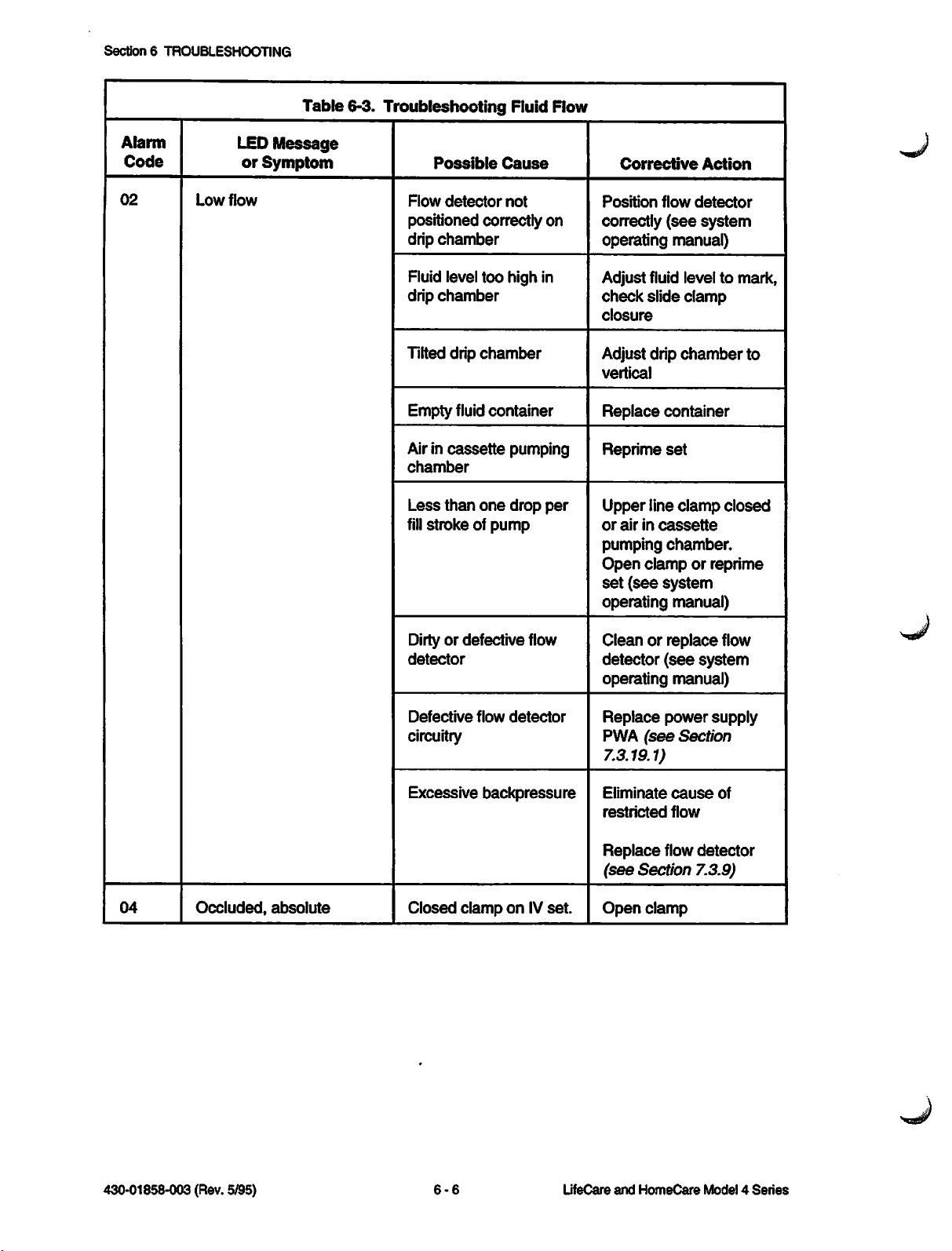
Section6TROUBLESHOOTING
Table
6-3.
Troubleshooting
Fluid Flow
Alarm
Code
02
Low
LED
or
flow
Message
Symptom
Flow
Possible
detector
Cause
not
positioned correctly on
drip
chamber
Fluid level too high in
drip
chamber
Tilted drip
chamber
Empty fluid container
Airin
cassette
chamber
Less
than
fill
stroke of pump
one
pumping
drop
per
Corrective
Position
correctly
operating
flow
(see
manual)
Action
detector
system
Adjust fluid level to
check
slide
clamp
closure
Adjust drip
vertical
Replace
Reprime
Upper
or
airincassette
pumping
Open
set
(see
chamber
container
set
line
clamp
chamber.
clamporreprime
system
operating manual)
mark,
to
closed
04
Occluded,
absolute
Dirtyor defective flow
detector
Defective
flow
detector
circuitry
Excessive
Closed
backpressure
clamp on IV
set.
Cleanorreplace
detector
(see
system
operating manual)
Replace
PWA
(see
power
Section
supply
7.3.19.1)
Eliminate
restricted
Replace
(see
Open
cause
flow
flow
detector
Section 7.3.9)
clamp
flow
of
430-01858-003 (Rev. 5/95)
6-6
LifeCare
and
HomeCare
Model4Series
Page 91

Alarm
Code
LED
or
Symptom
Table
Message
6-3.
Troubleshooting
Possible
Fluid
Cause
Flow
6.6
PUMP
TROUBLESHOOTING
Corrective
Action
05
06
07
08
Occluded,
Dose
end
CHECK
Wrong
cassette
differential
CASSETTE
Restrictions,
pinched
clogged
Pressure
such
as
tubing
or
filter
setting switch
inwrong position or faulty
Pressure
saturated
Dose
dose
Cassette
sensor
delivered
limit
not properly
PWA
equals
primed
Set
type switch in wrong
position (Micro only)
Wrong
cassette
installed
Find
and
remedy
restriction
Set
pressure
proper
replace
position or
(see
7.3.31)
Perform
calibration
pressure
and
Section 7.2.4)
Clear
dose
delivered
Reprime
Change
cassette
set
type switch
setting
Install proper
line
switch to
Section
sensor
test
cassette
(see
Technical
Service
Manual
6-7
430-01858-003 (Rev. 5/95)
Page 92

Section6TROUBLESHOOTING
Table
6-3.
Troubleshooting
Fluid Flow
Alarm
Code
12
Flow
LED
Message
or
Symptom
detector
inoperative
Possible
Flow
detector
connected
DET.
connector
to
Cause
not
FLOW
of pump.
Defective
Flow detector
flow
detector
presence
detection circuitry
defective
Corrective
Connect
(see
system
at
back
manual)
Replace
(see
Section 7.3.9)
flow
operating
flow
Action
detector
detector
Check DRPCH signal at
P6, pin43on motor
driver PWA. Signal
should
1
detectorisnot
connected
than1VDC
detectorisconnected.
VDC
be
when
less
and
flow
when
than
greater
flow
If
DRPCH signal is
incorrect,
supply PWA
replace
(see
power
Section 7.3.19.1).
Repair
connections
any
faulty
14
Occluded, amplifier failure
Dirtyflow
or
terminals
detector
pins
Misadjustedordefective
pressure
measuring
system.
Replace
connector
flow
pins
detector
(see
Section 7.3.11), or flow
detector
(see
Insert primed
and
not
pressure
pins 1
plug terminals
Section 7.3.10)
cassette
turn
pumponbut
start.
Measure
filter output,
and
5 on
motherboard. Voltage
should
+0.25
not,
be
and+0.97
see
between
Section
VDC.
5.2.6
do
J7,
If
430-01858-003 (Rev. 5/95)
6-8
LifeCare
and
HomeCare
Model4Series
Page 93

Table
6-3.
Troubleshooting
Fluid
Flow
6.6
PUMP
TROUBLESHOOTING
Alarm
Code
15
17
N/A
LED
Message
or
Symptom
Check
Check
Pump
than
delivers
than
rate
dose
delivers
less
setting,orconsistently
lessormore
setting.
fluid
fluid
Possible
Delivery rate is
when
pumpisstarted
single
solution
Secondary
Cause
000
mode
rate is
than primary rate in
piggyback
Secondary
rateisgreater
300
Dose
mode
or primary
than
ml/hr
limitis0000
(000.0 for Micro)
cassette
Airin
chamber
Excessive
pumping
backpressure
less
in
Corrective
Set
delivery rate to
desired
value
Increase
to a
value
primary
Reset
ml/hr
Set
value
rate
any
dose
Reprime
Eliminate
restricted
Action
secondary
greater
rate
limittodesired
than
over
set
cause
of
flow
rate
300
Alarm
Code
10
N/A
Symptom
Low
battery
Screen
blank,
inoperative,
alarm
(ornoalarm)
battery
power
Table
6-4.
pump
continuous
Defective
Misadjusted pump
mechanism
Incorrect
frequency
Troubleshooting
Discharged battery
Discharged battery
on
Possible
set
MPU
Battery
Cause
oscillator
Operations
Use
another
Contact
Laboratories
Check
set
Abbott
AS frequency on
MPU PWA U3, pin 6. If
not
1.0
MHz
±0.1%,
replace
MPU PWA
(see
Section 7.3.19.2)
Corrective
Connect
AC (mains)
Connect
AC (mains)
pump
power
pump
power
Action
to
to
Technical
Service
Manual
6-9
430-01858-003 (Rev. 5/95)
Page 94

Section6TROUBLESHOOTING
Alarm
Code
Symptom
Table
6-4.
Troubleshooting
Battery Operations
Possible
Cause
Corrective
Action
N/A
Operates
connected
power
on battery when
to AC (mains)
BlownAC (mains) power
fuse
Looseordefective
AC (mains)
power
cord
or powercord plug
Replace
Section 7.3.4)
measure
currentat350
fuse
(see
and
AC (mains)
ml/hr
(99.9 ml/hr, micro) with
dose
limit
active
For
100to120
VAC
devices,ifcurrent
exceeds
200
mA
RMS
(175 mA, micro), replace
power
supply PWA
(see
Section 7.3.19.1)
For
220to240
devices,ifcurrent
exceeds
replace
PWA
power
(see
100
Section
VAC
mA
supply
RMS,
7.3.19.1)
Check
power
Replace
Section
power
cord
power
7.3.20
cord
plug
cord
or
and
(see
Section 7.3.21)
430-01858-003 (Rev. 5/95)
Defective power supply
PWA
Replace
(see
Replace
PWA
power
cord
Section 7.3.7)
power
supply
(see
Section
7.3.19.1)
Defective primary circuit AC (mains) voltage on
component
power
supply PWA
between
should
between
measure
Otherwise,
pins 2
and
11
and17VAC.
check
P10
and
replaceasnecessary:
AC (mains)
(Section
Section 7.3.21),
cord
7.3.20
or
P10
(Section 7.3.25),
f
useholder
7.3.4.2
or
Section
(Section
7.3.29), or power supply
PWA
(Section 7.3.19.1)
6-10
LifeCare
and
HomeCare
Model4Series
plug
3
Page 95

Alarm
Code
N/A
Table
6-4.
Troubleshooting
Symptom
No
battery
short
battery
operation
or
Defective battery
operating time to low battery
alarm
Possible
Battery
Cause
Operat
pack
6.6
ions
Whenever
the
circuit
checked
Section
PUMP
TROUBLESHOOTING
Corrective
pack
battery
should
as
5.4.4
Action
a
defective
is replaced,
charging
be
described
in
Alarm
Code
Table
Symptom
6-5.
Troubleshooting
Discharged battery
pack
/^}—^X
f//r^^Y\\
1
[U<?fiCL/y^\
WB^y
^^^C~~~~\^^
ACC.
CONNECTOR
Possible
Core
Cause
\
MF18027
Failures
Replace
PWA
(see
power
Section
supply
7.3.19.1)
Before recharging, with
pump
disconnected
from
AC (mains) power,
measure
at
pin 6
(pin 5) of
connector).
voltageisless
7.2
battery
battery voltage
and
J23
VDC,
replace
pack
ground
(ACC.
Ifbattery
than
the
(see
Section 7.3.3)
Recharge
Corrective
battery
Action
pack
21
22
23
24
Technical
ROM
failure
Critical
data
Watchdog
processor
high frequency, or,
Watchdog
processor
low
frequency
Service
Manual
corrupted
does
when
does
when
not
reset
pulsed
not
reset
pulsed
Defective
PWA
Defective MPU PWA,
microprocessor,
only memories
Signal
generated
at
program is significantly
higher or lower
reference
at
Defective display driver
PWA, watchdog circuitry
Defective
6-11
ROM,
than
oscillator
MPU
MPU
read
by
PWA
Replace
MPU PWA
Section 7.3.19.2)
Replace
MPU PWA
Section 7.3.19.2)
Turn
main
control
off
and
on
three
times.
pump
still fails,
replace
display driver PWA
Section 7.3.19.2). If
pump
replace
continues
MPU PWA
to fail,
Section 7.3.19.2)
Replace
MPU PWA
Section 7.3.19.2)
430-01858-003 (Rev. 5/95)
(see
(see
switch
If
(see
(see
(see
Page 96

Section6TROUBLESHOOTING
Alarm
Code
25
Alarm
Code
31
32
Table
Symptom
Sanity
check
failure
Table
Symptom
Message
display filled,
reply not received
Numeric
display
registerfailure
6-5.
Troubleshooting
6-6.
Troubleshooting
shift
Core
Failures
Possible
Defective
PWA
Possible
Cause
ROM,
the
Cause
MPU
Pump
Microprocessordid not
receive proper signal,
indicating not all
characters
to
decoder/driver
were
written
Microprocessorfailed to
clear digit driver shift
registers on display
driver
PWA
Replace
Section 7.3.19.2)
Displays
Check
connection;
display PWA
Section 7.3.19.2) iffaulty
Replace
PWAormotor
PWA
7.3.19.2)
Corrective
MPU PWA
Corrective
for proper
display driver
(see
Action
(see
Action
replace
(see
driver
Section
34
33
35
Numeric display
failure
segment
Numeric display digit failure
Numeric display
greater
than
nine
data
failure
Defective
display,
Defective
displays or
drivers
numeric
segment
numeric
segment
drivers
Defective display driver
PWA, digit drivers
Defective
MPU
PWA
Replace
PWA
display driver
(see
Section
7.3.19.2)
Replace
PWA
display driver
(see
Section
7.3.19.2)
Replace
PWA
display driver
(see
Section
7.3.19.2)
Replace
MPU PWA
Section 7.3.19.2)
(see
430-01858-003 (Rev. 5/95)
6-12
LifeCare
and
HomeCare
Model4Series
Page 97

Table
6-7.
Troubleshooting
External
6.6
Controls
PUMP
TROUBLESHOOTING
Alarm
Code
41
42
43
Symptom
External UARTframing
error
External
RAM
failure
Accessory port failure
Table
6-8.
Troubleshooting
Possible
Defective
Defective
Cause
UART
MPU
PWA
ACRT1(RATE1)or
ACRT2 (RATE 2)
shortedtoground
Defective
motor
driver
PWA, output latch
circuitry
the
Pump
Corrective
Replace
PWA
7.3.19.2)
Replace
Section
Both
ground or high together.
Check
port,orreplace
pinsasnecessary
Replace
PWA
7.3.19.2)
Touchswitches
motor
(see
Section
MPU PWA
7.3.19.2)
signals
signals,
motor driver
(see
Section
Action
driver
must
clean
shorted
(see
be
Alarm
Code
51
Alarm
Code
61
Symptom
Touchswitch closed longer
than
163
seconds
Table
6-9.
Troubleshooting
Symptom
Motor
will
not
home
Possible
One
or more front
switch
signals
Cause
panel
shorted
ground
the
Pump
Possible
Mechanism
Cause
Misadjustedordefective
motor interrupter
Motor flag is
broken
loose
or
Defective motor voltage
supply
circuit
Corrective
to
Replace
replace
touchswitch
front
assemblyasnecessary
(see
Section 7.3.23)
Corrective
Contact
Laboratories
Contact
Laboratories
Abbott
Abbott
Replace power supply
PWA
(see
7.3.19.1)
Action
or
panel
Action
Section
Technical
Service
Manual
Defective
PWA
6-13
motor
driver
Replace
PWA
(see
motor
Section
driver
7.3.19.2)
430-01858-003 (Rev. 5/95)
Page 98

Section6TROUBLESHOOTING
Alarm
Code
63
64
66
Table 6-9. Troubleshooting
Symptom
Motorslipping or stuck
Motor slipped
three
times
in10cycles
Volume owed too great
because
motor slipping
the
Pump Mechanism
Possible
Defective
transistor
Cause
motor
Motor flag interrupter
defective
Defective
motor
Motorflag interrupter
defective
Motorflag detector
defective, dirty, broken,
or misadjusted
Defective power supply
PWA, motor flag
circuitry, motor voltage
regulator
Corrective
Replace
(see
PWA
Action
motordriver
Section
7.3.19.2)
Contact
Laboratories
Contact
Laboratories
Contact
Laboratories
Contact
Laboratories
Abbott
Abbott
Abbott
Abbott
Replace power supply
PWA
(see
Section
7.3.19.1),
check
motor
flag circuitry ground of
Q8onpower
PWA,
VMOT
measure
5 ±
supply
should
0.2
VDC
67
N/A
Rate/flag conflict
detected
Volume
because
by software
owed
too
motorslipping
as
great
Motor flag interrupter not
positioned correctly.
Pumping mechanism
binding or
Defective
stuck
MPU
PWA
Defective power supply
PWA, motor flag
circuitry, motor voltage
regulator
Motorflag interrupter
not
positioned correctly.
Pumping mechanism
binding or
stuck
Remove
of
measure
and
(measurements
pump
Replace
Q81;
0.20
ground for
VMOT
between
VDC
in reset)
MPU PWA
base
should
0.05
with
Section 7.3.19.2)
Replace
PWA
7.3.19.1),
(see
power
Section
check
supply
motor
flag circuitry ground of
Q8onpower
PWA, VMOT
measure
Remove
of
Q81;
measure
and
0.20
(measurements
pump
in reset)
supply
should
5 ±
0.2
ground for
VMOT
should
between
VDC
VDC
0.05
with
(see
base
430-01858-003 (Rev. 5/95)
6-14
LifeCare
and
HomeCare
Model4Series
Page 99

Alarm
Code
Table
Symptom
6-9.
Troubleshooting
the
Possible
Pump
Cause
6.6
Mechanism
PUMP
TROUBLESHOOTING
Corrective
Action
N/A
Alarm
Code
13
80
81
82
Rate/flag conflict
detected
Table
by software
6-10.
Troubleshooting
Symptom
Dataway
N/A
N/A
N/A
lost Dataway
as
Defective
the
communications
Installation
Dataway
Invalid
remote
Invalid
reset
Invalid request;
not
MPU
PWA
Dataway Function (RS-485 Only)
Possible
Cause
error
error
in
connector
request;
request;
not
not in
in
mode
correct
Replace
MPU PWA
(see
Section 7.3.19.2)
Corrective
RefertoLifeCare
4
Series
Action
Model
InfusionPumps
RS-485 Dataway
Technical Specification
Guide
and
Interface
Manual,
430-01761-XXX
P/N
83
84
85
86
87
N/A
N/A
N/A
N/A
N/A
Invalid request; primary
dose
off
Invalid
secondary
Invalid
operate
Transmission
checksum
Illegal
request;
dose
request;
incorrect;
error
command
off
not in
Technical
Service
Manual
6-15
430-01858-003 (Rev. 5/95)
Page 100

Section6TROUBLESHOOTING
Table
6-11.
Troubleshooting
the
Nurse-Call
Alarm
Symptom
Nurse-call
does
activate during
malfunction
Alarm
Code
11
Reset
minutes
not
alarm
Table
Symptom
more
or
6-12.
than
Possible
Cause
Defective power supply PWA,
nurse-call
Defective
Troubleshooting
five
circuits
main
Pump
longer
control
Miscellaneous
Possible
idle in
than
five minutes
switch
Cause
reset
Corrective
Replace
(see
Section
Replace
Check
circuits
power
main control switch.
continuity of nurse-call
NCC,
Action
supply PWA
7.3.19.1)
NC1,
power supply PWA with main
control
LOAD/OFF
switchinboth
RECHARGE
LOCK/ON positions
Conditions
Corrective
mode
Press
[START],
[RESET],orturn
off
NC2
Action
press
pump
on
and
N/A
71
72
73
Screen
blank, pump
inoperative,
alarm
(or no alarm) on
AC (mains)
Power-up line
high within
power
Software
within 5
Watchdog
processor
160msof
on
not
ms
has
failure
continuous
power
does
not go
executed
period
caught
+5 VDC power supply
has
failed
Loose
PWAs
Defective MPU PWA,
input buffer
Defective ROM, MPU
PWA
Oneormore
improperly
defective
PWAs
connected
Replace
PWA
7.3.19.1)
RefertoSection
Reseat
Replace
Section 7.3.19.2)
Replace
Section 7.3.19.2)
Check
or
PWAs
Iffailure
Abbott
power
(see
Section
PWAs
MPU
MPU PWA
connections
persists,
Laboratories
supply
4.5.6.1
PWA
contact
(see
(see
of
all
430-01858-003 (Rev. 5/95)
6-16
LifeCare
and
HomeCare
Model4Series
 Loading...