

Page 1

—
ABB Sw itzerland Ltd.
Low Voltage Products
Fulachstrasse 150
CH-8201 Schaffhausen
Telefon +41 (0) 5 8 586 41 11
Telefax +41 (0) 58 58 6 42 22
abb.ch
—
We reser ve the right to make technical
changes or mod ify the contents of this
document without prior notice. With regard to purchase orders, the agreed particul ars shall prevail. AB B AG does not accept any re sponsibilit y whatsoever for
potential errors or possible lack of information in this document.
We reser ve all rights in this do cument and
in the subject m atter and illus trations con tained therein. Any reproduction, disclosure to third part ies or utiliz ation of its
content s – in whole or in pa rts – is forbid den
without pr ior written consent of ABB AG .
Copyright© 2017 ABB
All ri ghts reserved
© Copyr ight 2017 ABB . All rights re served.
Specifications subject to change without notice.
2CCC451059C0203 REV B Nov 2 017
Page 2

—
SMISSLINE
Technical catalogue
SMISSLINE TP-Touch proof system
Power and safety
Page 3

2 TECHNICAL CATALOGUE SMISSLINE TP-TOUCH PROOF SYSTEM POWER AND SAFETY
—
Power behind bars
The world’s safest socket system
Small cause, large effect: as the world’s first
pluggable socket system, SMISSLINE TP ensures
that load-free devices and components can be
snapped on and off under voltage without
the need for additional personal protective
equipment to guard against electrical hazards.
That opens up completely new prospects for you
when it comes to installation, operation and
flexibility.
New Power Bar System 250 A
The new 250 A system is now available in the
shape of the SMISSLINE TP. The busbars have
a rated amperage of 250 A and therefore allow
a end feed of 250 A. This extends the spectrum
of potential applications.
Page 4

SMISSLINE TP-TOUCH PROOF SYSTEM POWER AND SAFETY 3
—
Efficiency you can touch
Plug in components during ongoing
operation
Even safer: Protection against electrical hazards
We have upgraded our unique SMISSLINE TP
socket system even further through the addition
of a pioneering innovation. With the new
SMISSLINE TP system, components can now be
plugged in or unplugged load-free without any
risk from electrical current running through the
body.
The SMISSLINE TP pluggable socket system is
completely finger-safe (IP20B) – when devices are
plugged in and unplugged, the system is always
touch-proof. This means that SMISSLINE TP prevents any danger to personnel from switching
arcs or accidental arcing.
Even more flexible: make additions and changes
during on going operation
Pluggable devices can be added and changed
quickly, safely and simply during ongoing operation. And this can be done without any need for
personal protective equipment.
This means that you benefit from more flexibility,
savings on installation and maintenance – and
improved safety. SMISSLINE TP provides greater
availability and operating safety than conventional systems.
Page 5

4 TECHNICAL CATALOGUE SMISSLINE TP-TOUCH PROOF SYSTEM POWER AND SAFETY
—
Absolutely safe without protective equipment
The SMISSLINE TP principle taken further
The ingenious Click system
Using the SMISSLINE TP system’s unique SMISS
CLICK function, five different protective devices
can easily be plugged into one pluggable socket
system with integrated busbars. In this way, the
SMISSLINE system allows the uncomplicated,
modular, flexible distribution of power up to a
rated current of 250 A. Plugging in the devices
quickly and without problems is essential for
time-saving, cost-effective planning and
execution.
Current measurement system
The CMS is a system for current measurement of
electrical lines. The system consists of a Control
Unit and sensors with different measurement
ranges (20 A, 40 A, 80 A). The sensors measure alternating, direct and mixed currents (TRMS).
The sensors get connected to the Control Unit by
a flat cable. You can remotely query the measurement data via a RS485 interface (Modbus RTU).
Page 6

SMISSLINE TP-TOUCH PROOF SYSTEM POWER AND SAFETY 5
SMISSLINE TP: The successful system is now
finger-safe
With SMISSLINE TP, fitters no longer require
personal pro tective equipment, and so both the
fitting and the operation/expansion of the installation can now be carried out more safely,
faster and thus more efficiently.
The RANGE
- Miniature circuit-breaker 1-, 2-, 3- and 4-pole
- Residual-current circuit-breaker 2- and 4-pole
- Combined RCCB-MCB 2- and 4-pole
- Surge arrester type 2
- Switch disconnector
- Motor protection switch
- Busbar system, contact rails max. 125 A;
incoming system with max. 250 A
- Wide range of accessories
Worth knowing: All SMISSLINE TP devices are
downwardly compatible with the existing
SMISSLINE pluggable socket system!
SMISSLINE TP at a glance
- Safe: load-free plugging in and unplugging
possible under power
- Flexible: rapid replacement, easy expansion,
mixed-pole layout possible
- Economical: saves time and space thanks to
the plug-in technology
Page 7

6 TECHNICAL CATALOGUE SMISSLINE TP-TOUCH PROOF SYSTEM POWER AND SAFETY
—
Pro E Power and pro E energy
SMISSLINE TP in ABB enclosures
Horizontal device arrangement
Modules for a horizontal device arrangement
for the SMISSLINE TP system The DIN rails are
designed to be equipped with the SMISSLINE TP
socket base rows.
Vertical device arrangement
Modules for a vertical device arrangement have
cable laying grids for fastening the cables.
The DIN rails are designed to be equipped with
the SMISSLINE TP socket base rows; it is also
possible to connect the SMISSLINE TP additional
sockets (N/PE terminals).
Front view hor izontal modu les
Front view ver tical modules
Floor-s tanding cabinet fitted with module s for
SMISSLINE TP devices an d for pro M DIN rail mounting devices and for fuse switch disconnectors.
Page 8

SMISSLINE TP-TOUCH PROOF SYSTEM POWER AND SAFETY 7
—
Planning aid SMISSLINE TP socket base
Socket base calculation with
SMISSLINE TP Designer Software
In Panel Design Configurator: SMISSLINE TP Designer
The new SMISSLINE TP Designer is integrated into the base
version of the Panel Design Configurator. This ensures
that Panel Design Configurator now offers simple project
planning and calculation for the SMISSLINE TP socket base
system.
The SMISSLINE TP Designer allows you to select and configure ABB SMISSLINE TP products in a graphical environment:
Advantages at a glance:
- Full integration in Panel Design Configurator
- Cabinet and module selection in Panel Design
Configurator
is possible specifically for the SMISSLINE TP socket base
- Components are fitted to the socket base in a graphical
environment
- Full range of SMISSLINE TP products for selection
- Configuration of accessories
- Automatic equipping
- Support for positioning the power supply
Information on:
- Incoming and outgoing power
- Checking and display of space units, power and
power loss
- Technical specifications for devices including price
calculation (in Panel Design Configurator)
- Printing or export (in Panel Design Configurator) of parts
lists, construction drawings or tender specifications
Accessories dialogue box
- The combination of devices and additional components
(such as auxiliary and signal contacts) is fully supported
- Automatic insertion of component combinations
- Automatic component selection for left/right positioning
Page 9

8 TECHNICAL CATALOGUE SMISSLINE TP-TOUCH PROOF SYSTEM POWER AND SAFETY
—
Remote Power Panel – Data Center
Application Note
Backup protection
Based on backup and selectivity requirements a Molded Case Circuit Breaker
(XT4) is used to protect the Sub-Distribution. The rating can go up to 250 A
per MCCB if parallel incoming is used. The Backup protection complies with
IEC/EN 60898-1 and IEC/EN 60947-2 and allows industrial use. With the
integrated COM-Module all voltages, currents, power factors and status data
is available through a Modbus RTU interface.
Circuit Monitoring System Control Unit – CMS-700
RPP’s heart is the Control Unit CMS-700 which aggregates the current readings
from the CMS and the Power Quality Values to create consumption data and
generate alarms in case of system errors. In addition to the optional front door
touch display CP651-WEB, a generic Modbus TCP and SNMP interface is supported. Typically this protocols are used to interface the data center infrastructure management system – DCIM.
Circuit Monitoring System – open core and solid core sensors
ABB’s CMS is the most compact, neat and hassle-free branch circuit monitoring
system available on the market. The sensors are mounted directly on the
SMISSLINE Miniature Circuit Breakers and there is no need of conventional
expensive and cumbersome cabling thanks to internal Modbus instead of typical
Current Transformer star wiring. The new range of open core sensors helps
to add branch monitoring into existing installations without the need to power off they system.
Touch proof system - SMISSLINE TP
The world’s first pluggable and touch proof socket system, SMISSLINE TP ensures
that load-free devices and components can be safely snapped on and off under
voltage without shutting down one single server. In addition maintenance can be
done by instructed personnel without electrician’s qualification. Moreover you
can save 20 % space for the typical A/B distribution in a data center. Compared to
a conventional build up time of 15 hours of an RPP like this – SMISSLINE needs only
8h which allows another 45 % of time saving.
Power Quality Analyzer
The Power Quality Analyzer has dual function. First, it provides the voltage and
power factor reference value to the PLC for calculating the effective power and
energy values for the branch circuit. It allows the class III system reports according to DIN EN 61000-2-4 secondly, it provides the following data for the complete
RPP:
- Active, reactive and apparent power
- Residual current monitoring
- Voltage quality (DIN EN 50160)
- Frequency and power factor
- Total harmonic distortion
Page 10

SMISSLINE TP-TOUCH PROOF SYSTEM POWER AND SAFETY
—
Remote Power Panel Range
Different sizes for different applications
Remote Power Panel families and technical features
compared at a glace:
na
Rated current of the assembly (I
Rated operational voltage 240/415 VAC
Number of branch circuits
per system
Operating temperature
Storage temperature -25 … +70 °C
CMS-700 Control Unit Communication Modbus RTU (RS485); Modbus TCP/IP; SNMP v1/2 and encrypted SNMP v3
Display Integrated webserver (CMS-700); optional front door device/display
Dimensions (mm) H x W x D 1950/550/350 1950/550/350 1950/800/350 1950/1050/350
) 250A 2x250A 3x250A 4x250A
with remote tripping
indication
with overvoltage module 112 112 168 222
with MID meter 42 42 63 84
Accuracy voltage
measurement
Accuracy branch current
measurement
RPP-250A RPP-500A RPP-750A RPP-1000A
128 128 192 256
84 84 128 170
-5 ... +40 °C
±1 %
±1 % full scale
—
International type numbering of ABB data center solutions
Example type number: RPP-500A-NP-INT-OVR-MID-PQ-TS
Electrical Specification Monitoring and Features
X1 X2 X3 X4 X5 X6 X7 X8
Product Input current Protection MCCB place-
RPP 250A P (single phase) INT (internal) Not selected Not selected Not selected Not selected
500A NP (phase and
neutral)
750A 3P (three phase) SINT (single line
1000A 3NP (three pha-
se and neutral)
KXXX
(tolerant tripping curve)
ment
EXT (external) RTI (remote
with internal)
SEXT (single line
with external)
Features Branch measu-
tripping indication)
OVR (overvoltage protection)
RTIOVR
(combination
RTI&OVR)
rement
BCM (branch
monitoring)
MID (billing
meters)
Power& network
analyzing
NET (network
analyzer)
PQ (power quality analyzer)
Display/Touch
TS (panel pc/
touchscreen)
Page 11
10 TECHNICAL CATALOGUE SMISSLINE TP-TOUCH PROOF SYSTEM POWER AND SAFETY
—
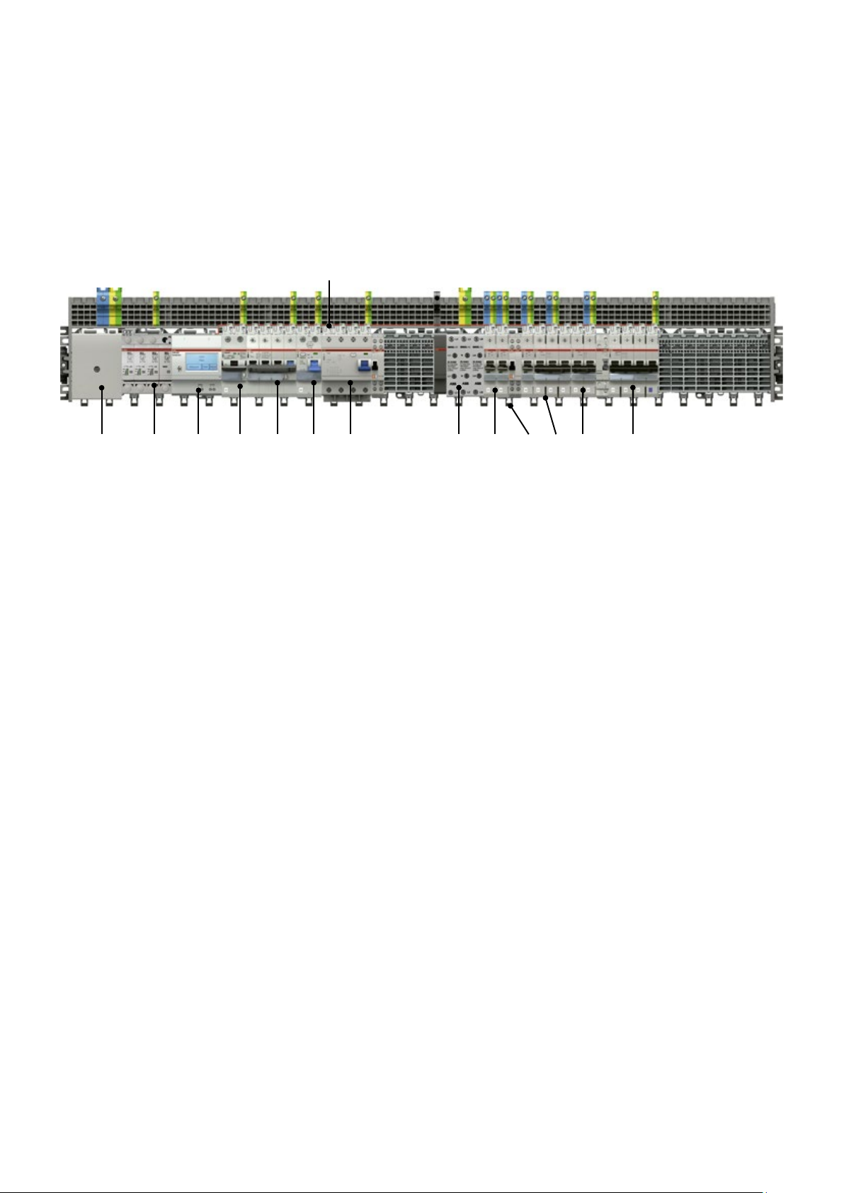
Six protection devices in one system
14
3 4 5 6 7 138 1210 1121 9
1 Incoming block 100/160 A
2 Surge arrester
3 Control unit for Current measurement
system
4 2-pole residual current operated
circuit breaker
with overcurrent protection
5 4-pole residual current operated
circuit breaker
with overcurrent protection
6 2-pole residual current operated
circuit breaker
7 4-pole residual current operated
circuit breaker
8 Incoming block 63 A
9 Miniature circuit breaker 1 pole
10 Device latch
11 Miniature circuit breaker 3 poles
12 Miniature circuit breaker 2 poles
13 4-pole residual current operated
circuit breaker with overcurrent protection
14 Current measurement sensor
Page 12

—
Table of conteants
SMISSLINE TP
012 – 027 Miniature circuit breaker S400
028 – 033 Residual current operated
11SMISSLINE TP-TOUCH PROOF SYSTEM POWER AND SAFETY
circuit breaker FS401
034 – 035 Residual current operated
circuit breaker F402, F404
036 – 037 Surge arrester OVR,
Switch disconnector
038 – 040 Combi module ,
Adapter for motor starter
041 – 044 Auxiliary switches and
signal contacts, Shunt trip,
Neutral disconnector
045 – 048 Motor operating device
049 – 050 CMS- Circuit Monitoring System
051 – 064 Busbar system 125 A
065 – 070 Power Bar System 250 A
Page 13

2CCC410018Z0001
123
4
2CCC404023Z0001
12345
6
2CCC404024Z0001
2CCC404025Z0001
132457/N
6 8/N
123
4
2CCC404023Z0001
1 3N
N
12 TECHNICAL CATALOGUE SMISSLINE TP-TOUCH PROOF SYSTEM POWER AND SAFETY
—
Miniature circuit breaker
Properties
General Information
The SMISSLINE miniature circuit-breaker is an energy-restricting circuit-breaker that has
high performance values and that is equally suitable for the industrial sector, for commercial
use and for installation at home.
If a short-circuit occurs, it guarantees excellent selectivity conditions to upstream overcurrent circuit breakers while the load on equipment that is connected downstream is limited to
a minimum amount.
The most important features
- High rated breaking capacity of 10 kA or 6 kA
- Optimum ease of installation and connection
- The pole conductors are protected against accidental contact
- Tripping characteristic on B, C, D, K, UCZ/UCC
Miniature circuit-breaker in accordance with standard EN 60898-1
This standard is for electrical installation material for household installations and for similar
purposes. It regulates the use of miniature circuit-breakers by the layman up to a maximum
of 125 A, a voltage of 440 VAC and up to a maximum of 25 kA.
Miniature circuit-breaker in accordance with standard EN60947-2
This standard is for low-voltage material used for industrial purposes. It regulates the use of
circuit-breakers (and not miniature circuit-breakers) by qualified personnel up to a maximum
voltage of 1000 VAC or 1500 VDC. This standard does not recognise any maximum values
when it comes to current and breaking capacity. In practice, the standard is also applied to
miniature circuit-breakers.
Brief description of tripping
The SMISSLINE miniature circuit breakers have a
Oscillogram of a short-circuit current
interruption
current-limiting operation. They have two different releases acting on the mechanism.
1. Thermal release, operating with a time delay,
for overload protection
2. Electro-magnetic release plunger operated
for short-circuit protection.
They offer:
– high short-circuit breaking capacity
– high selectivity to the back-up fuse
– In the event of short-circuits, low
electrodynamic and heating effects
on the cable and the point of fault
location due to the drastically lim-
2
ited let through energy ei
dt.
IK · 2 = peak val ue of prospective sh ort-circuit current
i
= Max . peak let through current of circuit breaker S 400
D
U
= Supply voltage
n
U
= Arc voltage of circuit breaker
B
t
= Total interruption time
K
Page 14

—
Miniature circuit breaker
Technical data S400E, S400M
—
General data
Tripping characteristics B,C,D,K
Standards
Poles
Rated current I
Rated frequency f
Rated insulation voltage U
Rated impulse withstand voltage U
Overvoltage category III
Pollution degree
Rated operational voltage U
Min. operating voltage
Rated short-circuit capacity I
Energy limiting class
Reference Ambient Air Temperature for Overload Tripping
Electrical and Mechanical Endurance
Rated operational voltage U
Min. operating voltage
Rated ultimate short-circuit capacity I
Rated service short-circuit capacity I
Reference Ambient Air Temperature for Overload Tripping
Electrical and Mechanical Endurance
Mechanical Data
Housing
Toggle black
Mechanical endurance
Environmental conditions (damp heat)
Ambient temperature
Storage temperature
Installation
Standed Cross-section of conductors (top/bottom)
Tightening torque
Screwdriver
Mounting plug in on bus bar system SMISSLINE
Mounting position any
Supply any
Dimensions and weight
Pole dim ension s (H x D x W)
Pole weight
n
i
e
e
imp.
cn
cu
cs
13SMISSLINE TP-TOUCH PROOF SYSTEM POWER AND SAFETY
Page 15

14 TECHNICAL CATALOGUE SMISSLINE TP-TOUCH PROOF SYSTEM POWER AND SAFETY
—
Miniature circuit breaker
Technical data S400UC
General data
Tripping characteristics UCC, UCZ
Standards
Poles
Rated current I
Rated frequency f
Rated insulation voltage U
Rated impulse withstand voltage U
Overvoltage category III
Pollution degree
Rated operational voltage U
Min. operating voltage
Rated ultimate short-circuit capacity I
Rated service short-circuit capacity I
Reference Ambient Air Temperature for Overload Tripping
Electrical and Mechanical Endurance I
Mechanical Data
Housing
Toggle black
Mechanical endurance
Environmental conditions (damp heat)
Ambient temperature
Storage temperature
Installation
Standed Cross-section of conductors (top/bottom)
Tightening torque
Screwdriver
Mounting plug in on bus bar system SMISSLINE
Mounting position any
Supply any
Dimensions and weight
Pole dim ension s (H x D x W)
Pole weight
n
i
e
imp.
cu
cs
n
I
n
Page 16

1
2
2CCC410018Z0001
2CCC404019Z0001
13
24
2CCC404020Z0001
13245
—
Miniature circuit breaker
Series S400 E–B, Icn = 6 kA
—
I
cn
[kA]
6
Ordering details for aux iliary switch and signal contac ts on page 41 – 45
I
[A]
n
Type name ABB IT number EAN number
Packaging
unit
15SMISSLINE TP-TOUCH PROOF SYSTEM POWER AND SAFETY
Module Weight
in
grams
Page 17
1
2
2CCC410018Z0001
2CCC404019Z0001
13
24
2CCC404020Z0001
13245
16 TECHNICAL CATALOGUE SMISSLINE TP-TOUCH PROOF SYSTEM POWER AND SAFETY
—
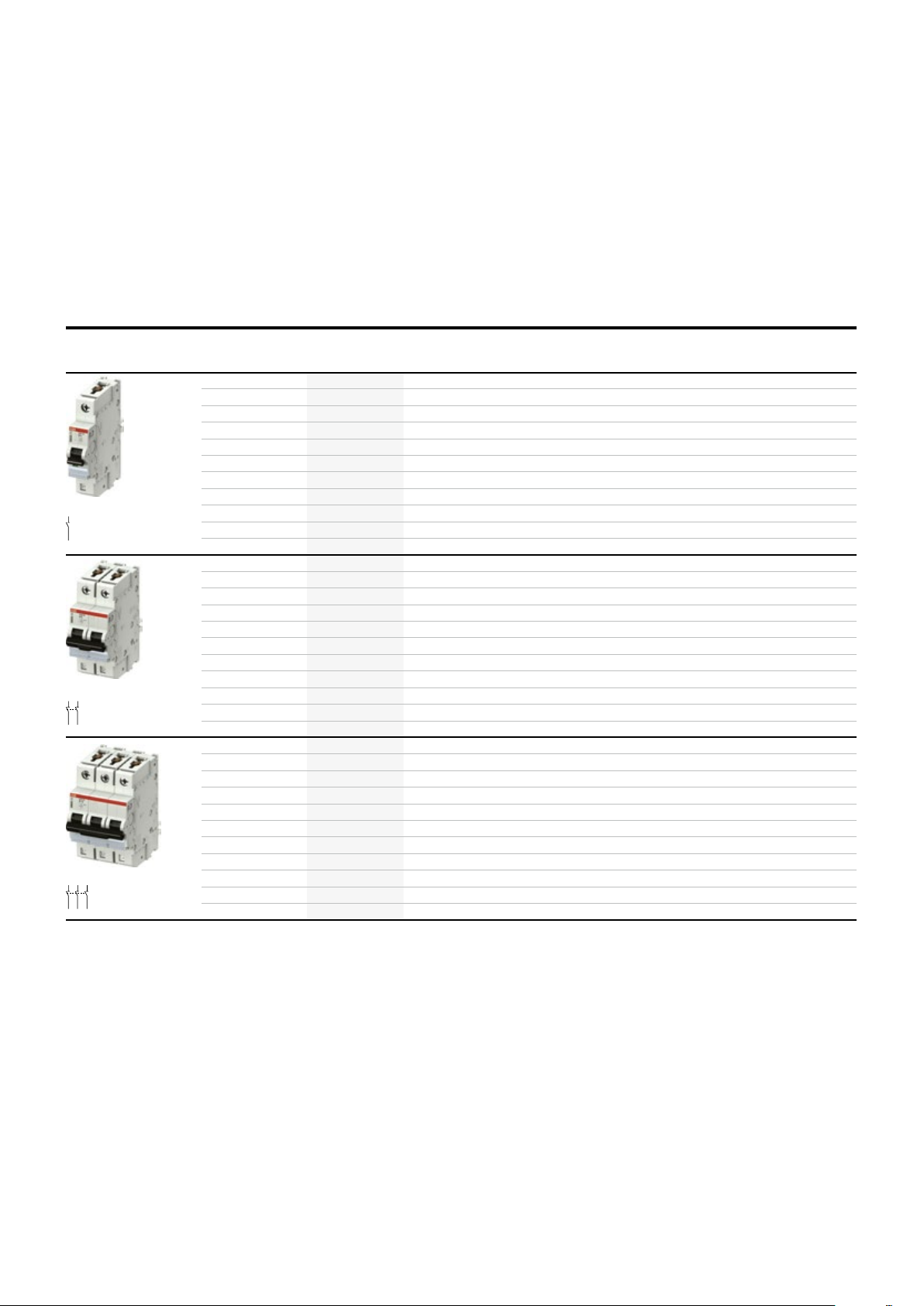
Miniature circuit breaker
Series S400 E–C, Icn = 6 kA
—
I
cn
[kA]
6
Ordering details for aux iliary switch and signal contac ts on page 41 – 45
I
[A]
n
Type name ABB IT number EAN number
Packaging
unit
Module Weight
in
grams
Page 18

2CCC404019Z0001
13/N
2 4/N
2CCC404021Z0001
1 3
2 4
5 7/N
6 8/N
—
Miniature circuit breaker
Series S400 E–C NP with protected neutral, Icn = 6 kA
—
I
cn
[kA]
I
[A]
n
Ordering details for aux iliary switch and signal contac ts on page 41 – 45
Type name ABB IT number EAN number
Packaging
unit
Module Weight
in
grams
17SMISSLINE TP-TOUCH PROOF SYSTEM POWER AND SAFETY
Page 19

2CCC404020Z0001
13245
6
2CCC404023Z0001
1
2
2CCC410018Z0001
18 TECHNICAL CATALOGUE SMISSLINE TP-TOUCH PROOF SYSTEM POWER AND SAFETY
—
Miniature circuit breaker
Series S400 M–B, Icn = 10 kA
—
I
cn
[kA]
1 3/N
2 4/N
Ordering details for aux iliary switch and signal contac ts on page 41– 45
I
[A]
n
Type name ABB IT number EAN number
Packaging
unit
Module Weight
in
grams
Page 20

2CCC404020Z0001
13245
6
2CCC404023Z0001
2 4/N
1
2
2CCC410018Z0001
—
Miniature circuit breaker
Series S400 M–C, Icn = 10 kA , Icu = 15 … 25 kA
—
I
1 3/N
EN
cu
[kA]
EN
I
cn
[kA]
I
[A]
n
Type name ABB IT number EAN number
Packaging
unit
19SMISSLINE TP-TOUCH PROOF SYSTEM POWER AND SAFETY
Module Weight
in
grams
Page 21

2CCC404020Z0001
13245
6
2CCC404023Z0001
3/N
1
2
2CCC410018Z0001
20 TECHNICAL CATALOGUE SMISSLINE TP-TOUCH PROOF SYSTEM POWER AND SAFETY
—
Miniature circuit breaker
Series S400 M–D, Icn = 10 kA
—
I
cn
[kA]
I
[A]
n
1
2 4/N
Ordering details for aux iliary switch and signal contac ts on page 41– 45
Type name ABB IT number EAN number
Packaging
unit
Module Weight
in
grams
Page 22

2CCC404020Z0001
13245
6
2CCC404023Z0001
2 4/N
1
2
2CCC410018Z0001
—
Miniature circuit breaker (MCB)
Series S400 M–K, Icu = 15 … 25 kA
—
1 3/N
I
cn
[kA]
I
[A]
n
Type name ABB IT number EAN number
Packaging
unit
21SMISSLINE TP-TOUCH PROOF SYSTEM POWER AND SAFETY
Module Weight
in
grams
Page 23

2CCC404021Z0001
2CCC404023Z0001
1 3/N
22 TECHNICAL CATALOGUE SMISSLINE TP-TOUCH PROOF SYSTEM POWER AND SAFETY
—
Miniature circuit breaker
Series S400 M–B with protected neutral Icn = 10 kA
—
I
cn
[kA]
2 4/N
1 3
5 7/N
2 4
6 8/N
Ordering details for aux iliary switch and signal contac ts on page 41– 45
The neu tral is protec ted with 100% of the nominal v alue of the pole conductor
I
[A]
n
Type name ABB IT number EAN number
Packaging
unit
Module Weight
in
grams
Page 24

2CCC404021Z0001
1 3
5 7/N
2CCC404023Z0001
1 3/N
—
Miniature circuit breaker (MCB)
Series S400 M–C with protected neutral Icn = 10 kA,
Icu = 15 … 25 kA
—
I
EN
cu
[kA]
2 4/N
2 4
6 8/N
Ordering details for aux iliary switch and signal contac ts on page 41– 45
The neu tral is protec ted with 100% of the nominal v alue of the pole conductor
EN
I
cn
[kA]
I
[A]
n
Type name ABB IT number EAN
number
Packaging
unit
Module Weight
23SMISSLINE TP-TOUCH PROOF SYSTEM POWER AND SAFETY
in
grams
Page 25
2CCC404021Z0001
2CCC404023Z0001
2 4/N
24 TECHNICAL CATALOGUE SMISSLINE TP-TOUCH PROOF SYSTEM POWER AND SAFETY
—
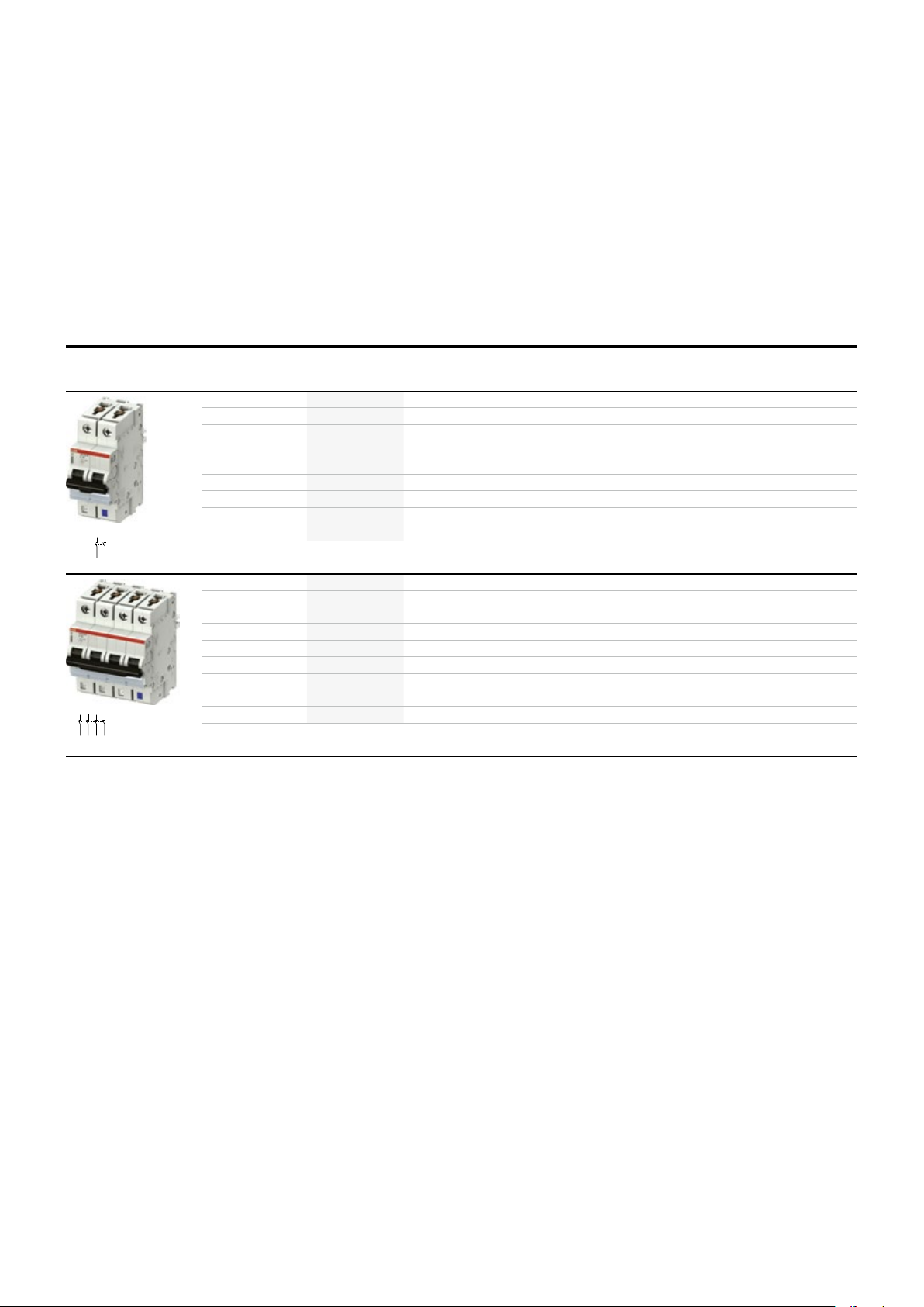
Miniature circuit breaker
Series S400 M–D with protected neutral Icn = 10 kA
—
1 3/N
I
cn
[kA]
I
[A]
n
Type name ABB IT number EAN number
Packaging
unit
Module Weight
in
grams
1 3
5 7/N
2 4
6 8/N
Ordering details for aux iliary switch and signal contac ts on page 41– 45
The neu tral is protec ted with 100% of the nominal v alue of the pole conductor
Page 26

2CCC404021Z0001
2CCC404023Z0001
1 3/N
2 4/N
—
Miniature circuit breaker
Series S400 M–K with protected neutral Icu = 15 … 25 kA
—
I
cu
[kA]
1 3
5 7/N
2 4
6 8/N
Ordering details for aux iliary switch and signal contac ts on page 41– 45
The neu tral is protec ted with 100% of the nominal v alue of the pole conductor
I
[A]
n
Type name ABB IT number EAN number
Packaging
unit
Module Weight
in
grams
25SMISSLINE TP-TOUCH PROOF SYSTEM POWER AND SAFETY
Page 27

+2
Z200445.eps
Z200446.eps
1 3
+2 4–
1
2
1
2
1
2
3
4
1
2
3
4
26 TECHNICAL CATALOGUE SMISSLINE TP-TOUCH PROOF SYSTEM POWER AND SAFETY
—
Miniature circuit breaker
Series S400 M-UC, application,
Icu = 10 … 25 kA
—
I
n
[A]
1 P 220 V=
1
2 P 440 V=
Ordering details for aux iliary switch and signal contac ts on page 41– 45
Type name ABB IT number EAN number
Packaging
unit
Module Weight
in
grams
Connection diagram, Connection diagram,
single-pole (max. 220 V=) S401M-UCC two-pole (max. 440 V=) S402M-UCC
Load
Mains
Load
Mains
Page 28

+2
Z200445.eps
Z200446.eps
1 3
+2 4–
1
2
1
2
1
2
3
4
1
2
3
4
—
Miniature circuit breaker
Series S400 M–UC, DC application,
Icu = 10 … 25 kA
—
I
n
[A]
1 P 220 V=
1
2 P 440 V=
Ordering details for aux iliary switch and signal contac ts on page 41– 45
Type name ABB IT number EAN number
Packaging
unit
27SMISSLINE TP-TOUCH PROOF SYSTEM POWER AND SAFETY
Module Weight
in
grams
Connection diagram, Connection diagram,
single-pole (max. 220 V=) S401M-UCZ two-pole (max. 440 V=) S402M-UCZ
Load
Mains
Load
Mains
Page 29

1/2 3/4/N
2CCC404027Z0001
28 TECHNICAL CATALOGUE SMISSLINE TP-TOUCH PROOF SYSTEM POWER AND SAFETY
—
Residual current operated circuit breaker
FS401
Residual current operated circuit breakers with
overcurrent protection (RCBO)
The SMISSLINE residual current operated circuit
breakers with overcurrent protection (RCBO) are
ideal for protecting people and property in all
new and existing distribution systems. The com-
bination of standby current and cable protection
2/1 4/3/N
in one single device greatly simplifies planning
and offers cost benefits. Using a RCBO can e.g.
satisfy the minimum level of protection required
by regulations in an apartment or in a particular
Typ e: RCD Type A Type F, short delay ARP
Rated voltage U
Number of poles:
Rated frequency f
Rated breaking capacity I
Current limitation class:
Total cut-off time (average value) acc. to
– at I
n
Minimum voltage for test button
Connection cross-sections
Terminal at load end
Degree of protection:
Endurance:
Resistance to climate, acc. to:
Mounting position: any any
Ambient temperature:
Vibration resistance:
Rated peak withstand current:
Plastic parts: halogen-free halogen-free
Contacts: cadmium-free cadmium-free
Please notice:
For the influe nce of the ambient temperature and the therm al influences of row mounted RCBO’s it i s necessary to calculate
with the same correc tion factors like w ith MCB’s.
:
n
:
n
:
cn
Opposing action stroke clamp on cylinder, touch finger-proof.
Suitable for connecting single, multi- and fine-wire conductors
distribution system. Should a residual current
arise, only the circuit directly affected is switched
off while all other circuits remain in operation.
The short time-delayed residual current operated
circuit breaker with overcurrent protection FS401
K is a version particularly suited to unfavourable
distribution and load situations. Without limiting
the personal protection function in any way, the
electronic short time delay prevents nuisance
tripping which may arise as a result of capacitive
discharge currents.
Page 30
2CCC404027Z0001
2/1 4/3/N
2CCC404027Z0001
1/2 3/4/N
2CCC404027Z0001
1/2 3/4/N
2/1 4/3/N
2CCC404027Z0001
—
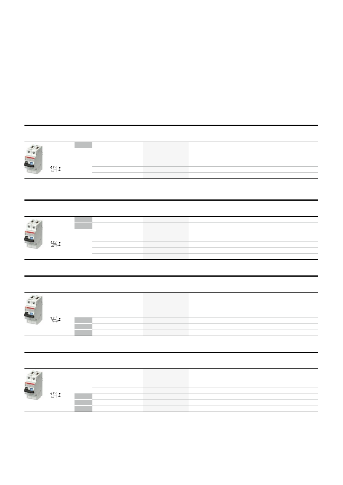
Residual current operated circuit breaker
with overcurrent protection
Series FS401 LN, Type A
—
I
I
Type name ABB IT number EAN
cn
[kA]
number
1/2 3/4/N
2/1 4/3/N
I
[A]
n
[mA]
new
Packaging
unit
29SMISSLINE TP-TOUCH PROOF SYSTEM POWER AND SAFETY
Module Weight
in
grams
—
I
[A]
I
n
cn
[kA]
I
[mA]
new
new
1/2 3/4/N
—
I
[A]
I
n
cn
[kA]
I
[mA]
2/1 4/3/N
new
new
new
—
I
[A]
I
n
cn
[kA]
I
[mA]
new
new
new
Ordering details for aux iliary switch and signal contac ts on page 41– 45
Type name ABB IT number EAN
number
Type name ABB IT number EAN
number
Type name ABB IT number EAN
number
Packaging
unit
Packaging
unit
Packaging
unit
Module Weight
in
grams
Module Weight
in
grams
Module Weight
in
grams
Page 31

1/2 3/4/N
2/1 4/3/N
2CCC404027Z0001
2/1 4/3/N
2CCC404027Z0001
2/1 4/3/N
2CCC404027Z0001
2CCC404027Z0001
30 TECHNICAL CATALOGUE SMISSLINE TP-TOUCH PROOF SYSTEM POWER AND SAFETY
—
Residual current operated circuit breaker with
overcurrent protection
Series FS401 LN, Typ F and short delay
—
I
I
I
[A]
n
[mA]
new
new
new
new
new
new
new
Type name ABB IT number EAN
cn
[kA]
number
Packaging
unit
Module Weight
in
grams
—
I
[A]
I
n
cn
[kA]
I
[mA]
new
new
new
1/2 3/4/N
new
new
new
new
—
I
[A]
I
n
cn
[kA]
I
[mA]
new
new
new
1/2 3/4/N
2/1 4/3/N
new
new
new
new
—
I
[A]
I
n
cn
[kA]
I
[mA]
new
new
new
1/2 3/4/N
new
new
new
new
Ordering details for aux iliary switch and signal contac ts on page 41– 45
Type name ABB IT number EAN
number
Type name ABB IT number EAN
number
Type name ABB IT number EAN
number
Packaging
unit
Packaging
unit
Packaging
unit
Module Weight
in
grams
Module Weight
in
grams
Module Weight
in
grams
Page 32

—
Residual current operated breaker RCBO
FS403
31SMISSLINE TP-TOUCH PROOF SYSTEM POWER AND SAFET Y
4-pole RCBO from the ABB SMISSLINE protective
devices range
The combination of circuit protection and a
residual current protection in one device as
4-pole RCBO simplifies both – planning and
installation. It enables you to provide perfect
protection
in one device. This protection consists of:
- Short circuit protection
- Overload protection
- Residual current protection
- Preventive fire protection
High rated short-circuit breaking capacity of
10 kA, conforming to EN 61009-1
10 kA short-circuit breaking capacity of the
The I
cn
RCBO complies with standard EN 61009-1.
This standard specifies testing and usage of
RCBO’s for household and similar uses.
The devices can also be used by non-professionals.
Features and benefits of the new devices:
- Overall width of 72 mm (4 modules)
- Rated sensitivity 30 mA
- Current rating 10 A to 32 A
- B and C tripping characteristics
- Easy Drive double deck terminals on the output side for connecting two conductors in one
chamber. The two chambers can accommodate conductors with different cross sections.
Typ e: RCD Type A, Type F, short delay ARP
Rated voltage U
Number of poles:
Rated frequency f
Rated breaking capacity I
Current limitation class:
– at I
Minimum voltage for test button
Standed Cross-section of conductors (top/bottom)
Tightening torque:
Degree of protection:
Endurance:
Resistance to climate:
Ambient temperature:
Vibration resistance:
Plastic parts:
contacts:
Approvals and standards:
:
n
:
n
:
cn
halogen free, according
cadminum free
Accessory:
Auxiliar y- and signal contac ts are to attach on to the lef t of the device through the cu stomer.
Page 33
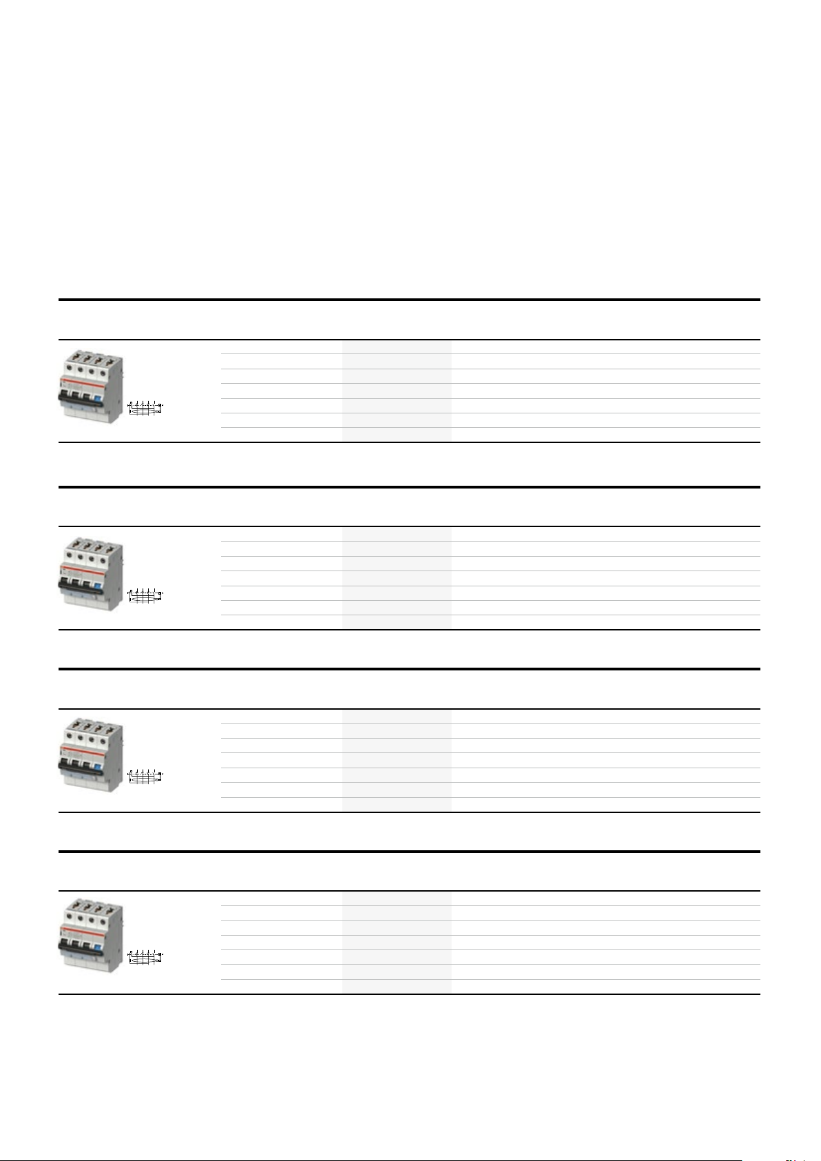
1/2 3/4 5/6 7/8/N
2/1 4/3 6/5 8/7/N
2CCC451099Z0001
2/1 4/3 6/5 8/7/N
2CCC451099Z0001
2/1 4/3 6/5 8/7/N
2CCC451099Z0001
2CCC451099Z0001
32 TECHNICAL CATALOGUE SMISSLINE TP-TOUCH PROOF SYSTEM POWER AND SAFET Y
—
Residual current operated circuit breaker with
overcurrent protection
Series FS403 3LN, Type A
—
I
I
I
[A]
n
[mA]
Type name ABB IT number EAN
cn
[kA]
number
Packaging
unit
Module Weight
in
grams
—
I
[A]
I
n
cn
[kA]
I
[mA]
1/2 3/4 5/6 7/8/N
—
I
[A]
I
n
cn
[kA]
I
[mA]
1/2 3/4 5/6 7/8/N
—
I
[A]
I
n
cn
[kA]
I
[mA]
1/2 3/4 5/6 7/8/N
2/1 4/3 6/5 8/7/N
Ordering details for aux iliary switch and signal contac ts on page 41– 45
Type name ABB IT number EAN
number
Type name ABB IT number EAN
number
Type name ABB IT number EAN
number
Packaging
unit
Packaging
unit
Packaging
unit
Module Weight
in
grams
Module Weight
in
grams
Module Weight
in
grams
Page 34

1/2 3/4 5/6 7/8/N
2CCC451099Z0001
2/1 4/3 6/5 8/7/N
2CCC451099Z0001
1/2 3/4 5/6 7/8/N
2CCC451099Z0001
—
Residual current operated circuit breaker with
overcurrent protection
Series FS403 3LN, Type F short delay
—
I
I
Type name ABB IT number EAN
cn
[kA]
number
VPE Module Weight
2/1 4/3 6/5 8/7/N
I
[A]
n
[mA]
new
new
new
new
new
new
new
33SMISSLINE TP-TOUCH PROOF SYSTEM POWER AND SAFET Y
in
grams
—
new
new
new
new
2/1 4/3 6/5 8/7/N
new
new
new
—
new
new
new
1/2 3/4 5/6 7/8/N
new
new
new
new
I
[mA]
I
[mA]
I
[A]
I
[A]
I
n
Type name ABB IT number EAN
cn
[kA]
number
I
n
Type name ABB IT number EAN
cn
[kA]
number
VPE Module Weight
in
grams
VPE Module Weight
in
grams
Page 35

34 TECHNICAL CATALOGUE SMISSLINE TP-TOUCH PROOF SYSTEM POWER AND SAFETY
—
Residual current operated circuit breaker F402, F404
Technical data
RCD Ty pe: Type A Typ e A
Rated voltage U
Number of poles:
Rated frequency f
Rated breaking capacity I
Total trip time (average value)
– at I
Resistance to short circuits (kA):
Connection
load side terminal
Degree of protection:
Endurance:
Resistance to climate acc. to:
Mounting position: any any
Ambient temperature:
Vibration resistance:
Plastic parts: halogen-free halogen-free
Contacts: cadmium-free cadmium-free
:
n
: / Hz)
n
: – –
:
m
#
#
in conjunction with an upstream fuse
Double lift terminal touch finger-proof, suitable for connecting
#
#
in conjunction with an upstream fuse
Rated voltage U
Number of poles:
Rated frequency f
Resistance to surge current:
Total trip time (average value)
– at I
Resistance to short circuits (kA):
Connection
load side terminal
Degree of protection:
Endurance:
Resistance to climate acc. to:
Mounting position: any any any
Ambient temperature:
Vibration resistance:
Plastic parts: halogen-free halogen-free halogen-free
Contacts: cadmium-free cadmium-free cadmium-free
:
n
:
n
#
:
Double lift terminal touch finger-proof, suitable for connecting
Page 36

1/2 3/4
2/1 4/3
5/6 7/8/N
6/5 8/7/N
2CCC404028Z0001
2CCC404026Z0001
—
2- and 4-pole residual current operated circuit
breaker
F402, F404, Type A
35SMISSLINE TP-TOUCH PROOF SYSTEM POWER AND SAFET Y
I
mA
1/2 3/4/N
2/1 4/3/N
—
—
n
A
Type name ABB IT number EAN
I
number
E number Pack-
aging
unit
Module Weight
in
grams
—
—
—
Ordering details for aux iliary switch and signal contac ts on page 41– 45
/
Page 37

36 TECHNICAL CATALOGUE SMISSLINE TP-TOUCH PROOF SYSTEM POWER AND SAFETY
—
Surge arrester OVR
Technical data
Typ
Technologie varistor Varistor/gaz tube (N)
System network TNS TT–TNS
Electrical features
Standard
Type / test class
Number of pole
Nominal voltage UN (L-N, L-L)
Type of voltage
Max. cont. operating voltage U
Nominal discharge current I
Maximum discharge current I
Maximum impulse current I
Voltage protection level U
Voltage protection level U
Voltage protection level U
Voltage protection level U
TOV (Temporary overvoltage) withstand U
c
n
max
imp
at In (L-N / N-PE / L-PE)
p
p
p
p
t
Response time Response time
Short-circuit withstand capability Isccr
Back up prootection circuit breaker
Pluggable cartridge Yes Yes
Integrated QuickSafe® technology Yes Yes
State indicator Yes Yes
Auxiliary contact (TS) Yes Yes
Installation
Wire range (L, N, PE)
Connection cross-section
Tightening torque
Auxiliary contact (TS)
Contacts information
Max. load/current
Min. load/current
Operating temperature
Storage temperature
cable or rope
cable or rope
—
Back up protection
Surge Protective Devices
Prospective short circuit
current at SPD location (Ip)
Circuit breaker maximum ratings
curve B or C
Fuse
(gL - gG)
Maximum ratings
p
I
n
U
c
1)
Maximum ratings , must be in accordance w ith the installation to follow coor dination rul es with main or upstream shor t circuit protection(s).
2)
up to Ip
Page 38

2CCC404030Z0001
2CCC451190Z0001
2CCC451191Z0001
—
Surge arrester Type 2,
Switch disconnector
—
Isn
[kA]
Type name ABB IT number EAN number Pack-
aging
unit
37SMISSLINE TP-TOUCH PROOF SYSTEM POWER AND SAFET Y
Module Weight
in
grams
OVR404 4 L
OVR404 3 LN
—
I
n
[A]
1/2 3/4
5/6 7/8/N
2/1 4/3
6/5 8/7/N
Ordering details for auxiliary switch and signal contacts on page xx–xx
—
The Cover ist for the Incoming terminals
Type name ABB IT number EAN number
Type name ABB IT number EAN number
Packaging
unit
E number Pack-
Module Weight
aging
unit
in
grams
Weight
in
grams
Page 39

Manual motor starter
38 TECHNICAL CATALOGUE SMISSLINE TP-TOUCH PROOF SYSTEM POWER AND SAFETY
—
Combi module:
starting solutions in kit form
Mounting possibilities
Direct-On-Line Starters
MS116
MS116 up to 16 A
MS116 > 16 A
MS132
MS132 up to 10 A
MS132 > 10 A
with control voltage
Mounting possibilities on the combi module:
The following combinations of contactor, motor circuit
breaker and connector are possible on the combi module.
I >
MS...
BEA...
Connecting link
+
AF...
Contactor
Reversing Starters
MS116
MS116 up to 16 A
MS116 > 16 A
MS132
MS132 up to 10 A
MS132 > 10 A
without control voltage
+
I >
BEA...
Connecting link
AF...
Contactor
MS...
Manual Motor Starter
Fixing clip
VM4
Mechanical
interlock unit
VE4
Electrical
interlock block
A2
A2
BER..-4
Connection set
Page 40

—
Combi module 32 A (IN), 6 A (IA, IB)
MS116/132 + AF contactor
—
Designation Type name ABB IT number EAN
top feed
top feed
top feed
top feed
Combi module
without plug-in contacts
Connection pin to mont
Intermediate
Set of
number
Packaging
unit
39SMISSLINE TP-TOUCH PROOF SYSTEM POWER AND SAFET Y
Module Weight
in
grams
—
Designation Type name ABB IT number EAN
empty
Intermediate
Top feed Bottom feed
The 9 mm wide additional housing is need to use when an un equal number (1, 3, 5, …) of combi modules o r adapter are plugged on t he socket.
This is needed to f ill the space into a full module (18 mm).
The 9 mm wide additional housing can be also use when on one side of the ma nual motor star ter an auxili ary contact is mounte d.
The order codes of manua l motor starter and the contac tors auf in the AB B catalogue DOC 1SB C100155 C0202 or in the l ocal ABB catalogu e.
number
Packaging
unit
Module Weight
in
grams
Page 41

40 TECHNICAL CATALOGUE SMISSLINE TP-TOUCH PROOF SYSTEM POWER AND SAFETY
—
Adapter for motor starter
MS116, MS132, MS325
—
Designation Type name ABB IT number EAN
empty
Intermediate
moduls together
Set of
number
Packaging
unit
Module Weight
in
grams
—
Type name ABB IT number EAN number
—
Auxiliary switch and signal contacts, connection support
Contact pin, short
for power supply
via auxiliary busbars
ZMS 915 ⑤ MS325 /
ZLS 5.., In max. 32 A
ZMS 916 ⑤ MS325,
max. 20 A
I
n
ABB IT number EAN number
ZMS 917 ⑤ MS325,
max. 20 A
I
n
ZMS 918 ⑤ MS325,
max. 20 A
I
n
Packaging
unit
Packaging
unit
ZMS 919 ⑤ MS325,
max. 20 A
I
n
Weight
in
grams
Weight
in
grams
Page 42

2CCC451029Z0001
13 21
14 22
2CCC451029Z0001
13 21
14 22
2CCC451029Z0001
13 21
14 22
2CCC451031Z0001
97
98 06
2CCC451030Z0001
97
98
2CCC451030Z0001
97
98
—
Auxiliary switches and signal contacts
Description, Technical data
General
The auxiliary switches and signal contacts are snapped on to the left of the protective devices.
On the miniature circuit breakers an optional mounting on the right is also possible.
For auxiliary switches and signal contacts supplied via SMISSLINE auxiliary busbars LA or LB
a version with integrated contacting pieces is available Conventional supply via the terminals
of the auxiliary devices is possible.
Function
The auxiliary switch works in the same way as the main contacts. The signal contact only operates
when the protective device trips.
This can be simulated with the white test button. Each time the signal contact is tripped, it must be
reset to its starting position using the orange-coloured reset button.
Auxiliary switch and signal contacts have special contacts whitch ensure high switching reliability
even in systems with low voltages or low currents (PLC, signal systems etc.).
Auxiliary switch contacts operate at the same time as the contacts of the protective device
(activated manually or automatically).
Normally open contact
05
NO (normally open)
Normally open contact
NC (normally close)
Signal contacts only operate when the protective device is tripped electrically as a result of a shortcircuit, a fault current or overcurrent (undervoltage for MS325).
Normally open contact
NO (normally open)
Normally open contact
NC (normally close)
13
joint operation with protective device
14
21
opposing operation with protective device
22
97
closes during automatic trip
98
05
opens during automatic trip
06
41SMISSLINE TP-TOUCH PROOF SYSTEM POWER AND SAFETY
—
Technical data for auxiliary switch and signal contact
Signal contact
Rated voltage U
Rated impulse withstand voltage
Rated current
– I
th
Minimum current/voltage
(to ensure reliable electrical operation)
Connection cross-sections:
Plastic parts: Free of halogen und cadmium Free of halogen und cadmium
Internal resistance Ri:
Power loss at rated current Pv:
Ambient temperature:
Tightening torque:
n
strand with sleeve strand with sleeve
Auxiliary switch
Page 43

42 TECHNICAL CATALOGUE SMISSLINE TP-TOUCH PROOF SYSTEM POWER AND SAFETY
—
Accessory mounting
Options for protective devices
F404
IS404
SK
HK
AS4 00 / ZLS931
L2
F402
2 HK / 1 HK, 1 SK
L2
S400
SK
HK
AS4 00 / ZLS931
2 HK / 1 HK, 1 SK
T
SKHKAS4 00 / ZLS931
2 HK / 1HK , 1 SK
NT4 01
ZLS728
SK
AS4 00 / ZLS931
HK
2 HK / 1HK , 1 SK
F4C-CM
SKHKAS4 00 / ZLS931
T
N
T
N
F4C-ARI
F4C-CM
F4C-ARI
2 HKHKAS4 00 / ZLS931
S2C- A1/A2
NT4 02
2 HK / 1 HK, 1 SK
T
N
FS403
On each protective device can be mounted:
1 auxiliary switch
or 1 signal contact
or 2 auxiliary contact switches
or 1 auxiliary switch and 1 signal contact
Contact description signal contact
97
98
05
06
97
98
07
08
95
96
SK40011 SK40020 SK40002
Contact description auxiliary switch
13
14
21
22
13
14
23
24
11
12
SBS10 / SBS01
SBH11
ZLS930
2 SBH / 1 SBS, 1 SBH
1L15L33
L2
0
T12T16T1
4
MS325
2 HK / 1 HK, 1 SK
T
L2
FS401
SK
HK
ZLS933
05
06
21
22
If you use an auxiliary switch and a signal
contact you must connect first the signal
contact on the MS325.
Page 44

2CCC451029Z0001
13
14 22
2CCC451029Z0001
13 21
14 22
2CCC451029Z0001
13 21
14 22
2CCC451031Z0001
97 05
98 06
2CCC451030Z0001
97
98
2CCC451030Z0001
97
98
—
Auxiliary switch and signal contacts
MCB S400, RCCB F404, RCCB F402, RCBO FS401
The auxiliary switch and signal contacts are supplied with one contacting piece.
—
Auxiliary switch
21
The signal contact collective alarm are supplied with two contacting pieces.
Type name ABB IT number EAN number
Packaging
unit
43SMISSLINE TP-TOUCH PROOF SYSTEM POWER AND SAFET Y
Module Weight
in
grams
—
Signal contacts
—
Signal contact collective alarm and auxiliary contact
for left side mounting
for right side mounting
Type name ABB IT number EAN number
Type name ABB IT number EAN number
Packaging
unit
Packaging
unit
Module Weight
in
grams
Module Weight
in
grams
Collective alarm, signal contact contacts the auxiliary busbars LA, LB
A cost-effective collective alarm solution can be implemented without additional wiring by using this
arrangement.
Page 45

2CCC451028Z0001
C1
C2 C4
12C1
C2
12C1
C2
44 TECHNICAL CATALOGUE SMISSLINE TP-TOUCH PROOF SYSTEM POWER AND SAFETY
—
Dummy, housing, Neutral disconnector, shunt trip
—
Connection support dummy housing
Connection support Type name ABB IT number EAN number
Dummy housing
C3
Packaging
unit
Module Weight
in
grams
—
Contacting pieces for auxiliary switch and signal contacts
Connection
Type name ABB IT number EAN number
support
Contacting piece for
Pack
HK/SK LA, LB
Contacting piece for
Pack
HK/SK LA, LB
Contact Pin Pack
—
Neutral disconnector
On the load side terminal two separate conductors can be clamped
Connection support Type name ABB IT number EAN number
Neutral disconnector
Neutral disconnector
—
Shunt trip
Rated voltage Type name ABB IT number EAN number
Packaging
unit
contains
contains
contains
Packaging
unit
contains
Packaging
unit
Module Weight
in
grams
–
–
Module Weight
in
grams
Module Weight
in
grams
Orders for this two ty pes can be done over DESTO
Page 46

—
F4C-CM motor operating devices
Technical specifications
Supply voltage:
Insulation voltage:
Power consumption:
Power consumption at rest:
F400
2) After openi ng due to a fault, w ait 8 seconds be fore performing the remote r esetting.
F4C-CM
via free voltage contacts
Closing time at ambient temperature:
Opening time at ambient temperature:
Delay time for remote resetting after
opening due to fault:
Number of operations:
Operating temperature:
Storage temperature:
Fixing:
Cables length of control circuit:
Cable cross-section:
Rated current:
Command terminals:
(supplied by motor operating device)
45SMISSLINE TP-TOUCH PROOF SYSTEM POWER AND SAFETY
Wiring diagrams for F4C-ARI motor operating devices
Use at 230 V AC via a TM15/12 bell transformer
NL
LOCKED STATE
OFF
ON
12 345
LOCKED
AUX
678910 11
5678
TM15/2
1234
230 V AC
MAX 1500m
open
closed / reset
NL
LOCKED STATE
OFF
ON
12 34 5
LOCKED
AUX
678910 11
12-30 V AC
12-48 V DC
MAX 1500m
open
closed / reset
Page 47
46 TECHNICAL CATALOGUE SMISSLINE TP-TOUCH PROOF SYSTEM POWER AND SAFET Y
—
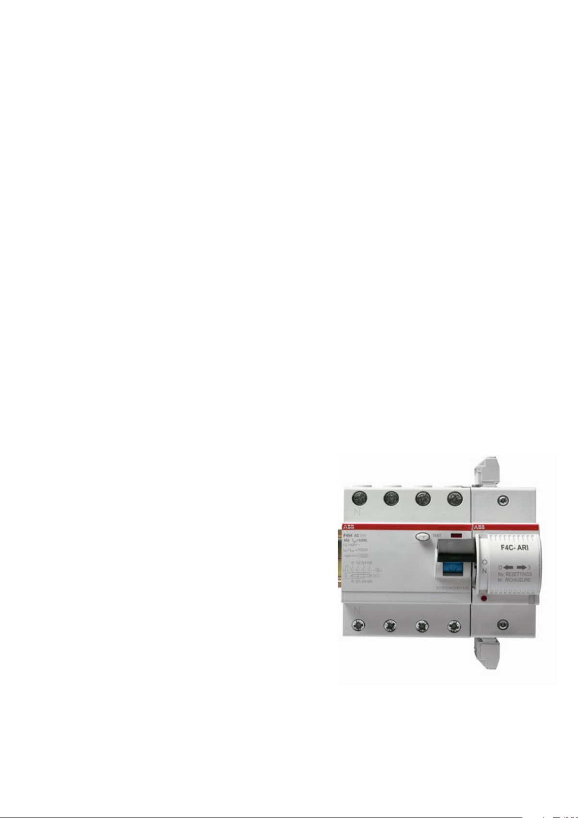
F4C-ARI auto-reclosing unit
Specific features
The F4C-ARI auto-reclosing device, installed to
the right side of the residual current circuit break-
ers, automatically performs three reclosing
attempts in the event of a fault. If the result of the
three reclosing attempts is negative, the device
enters a locked state.
The luminous two- colors red/green LED shows
the operating state of the auto-reclosing device.
- Blinking green LED: this is displayed for five
seconds after the device is powered up. When
the LED stops blinking, the device is ready to
operate.
- Steady green LED: the remote control is
activated and the device is powered.
- LED is off: no power supply.
- Blinking red LED: reclosing cycle in progress.
- Steady red LED: the remote control is excluded on the device or is in a locked state following three unsuccessful reclosing attempts,
or as a result of a remote opening command.
The lower section of the device contains an inte-
which indicates the position of the contacts of
the associated circuit breaker.
The associated residual current circuit breaker
can be remotely opened via a command with the
NO contact. The remote open command locks out
the resetting logic and brings the auto-reclosing
device into a locked state.
Operation of the close/reset and open commands
can be performed via an impulse command.
Remote commands and reclosing logic may be
deactivated locally by means of the mobile element on the front of the device. This is desirable
during maintenance interventions with the device
in the OFF position, in order to avoid remote-activated closing operations or automatic reclosing.
In this case, with the selector and the circuit
breaker in the OFF position, the device may be
physically locked by threading a padlock through
the with draw able element on the front.
The locked state can be reset:
- locally, by manually moving the mobile element on the front of the device to the OFF position and subsequently to the ON position.
The device will reset and automatically reclose
the circuit breaker;
- remotely, by means of a close command
(NO contact) which resets the device and
close the circuit breaker.
Using both of the resetting methods, the cycle of
three re closing attempts can be repeated.
Page 48

—
F4C-ARI motor operating devices
Technical specifications
Supply voltage:
Number of automatic reclosing attempts:
Counter reset time:
Insulation voltage:
Power consumption:
F400
F4C-ARI
Power consumption at rest:
Delay time for activation of automatic reclosing:
Reclosing time at ambient temperature:
Opening time at ambient temperature:
Number of operations:
Operating temperature:
Storage temperature:
rapid fi xing system
Cables length of control circuit:
Cable cross-section:
Rated current:
via dry contacts
Command terminals:
(supplied by motor operating device)
47SMISSLINE TP-TOUCH PROOF SYSTEM POWER AND SAFETY
Wiring diagrams for F4C-ARI motor operating devices
Low voltage use of several motor operating devices:
12 ... 30 V AC, 12 ... 48 V DC
12-48 V DC
12 345
LOCKED
AUX
67891011
closed / reset
open
1 2 n ...
12 345
LOCKED
AUX
67891011
closed / reset
open
12 345
LOCKED
AUX
67891011
closed / reset
open
Use of several motor operating devices at 230 V AC
via a single safety transformer
12-30 V AC 230 V AC
12 345
LOCKED
AUX
67891011
closed / reset
open
1 2 n ...
12 345
LOCKED
AUX
67891011
closed / reset
open
12 345
LOCKED
AUX
67891011
closed / reset
open
Page 49

48 TECHNICAL CATALOGUE SMISSLINE TP-TOUCH PROOF SYSTEM POWER AND SAFETY
—
F4C-ARI motor operating devices
—
Type name ABB IT number EAN number Packaging
unit
Modul Weight
in grams
For Supply vol tage 230V it is n eeded to use a safety transformer TS16/12 (2CSM161401R401R0811).
—
Type name ABB IT number EAN number Packaging
For Supply vol tage 230 V it is needed to use a safety transfor mer TS16/12 (2CSM161401R401R081 1).
—
Safety transformer
Type name ABB IT number EAN number Packaging
unit
unit
Modul Weight
in grams
Weight
in grams
Page 50

—
CMS – Current Measurement System
Technical data
Sensors
Measurement range
Measurement method
Crest factor of distorted wave forms
AC Temperature coefficient
DC Temperature coefficient
Resolution
Sampling rate internal
Cable feed through
Insulation Voltage
Weight
Dimensions B x H x T
49SMISSLINE TP-TOUCH PROOF SYSTEM POWER AND SAFETY
Control Unit
Supply voltage
Power dissipation
Interface
Protocol Modbus RTU
Data rate
Data refresh time
Insulation Voltage
Screw-type terminals
Mounting
Weight
Dimensions B x H x T
General Data Sensors and Control Unit
Operating temperature
Storage temperature
Electrostatic discharge (ESD)
Electromagnetic compatibility
(EMC)
or SMISSLINE TP busbar system
Page 51
50 TECHNICAL CATALOGUE SMISSLINE TP-TOUCH PROOF SYSTEM POWER AND SAFETY
—
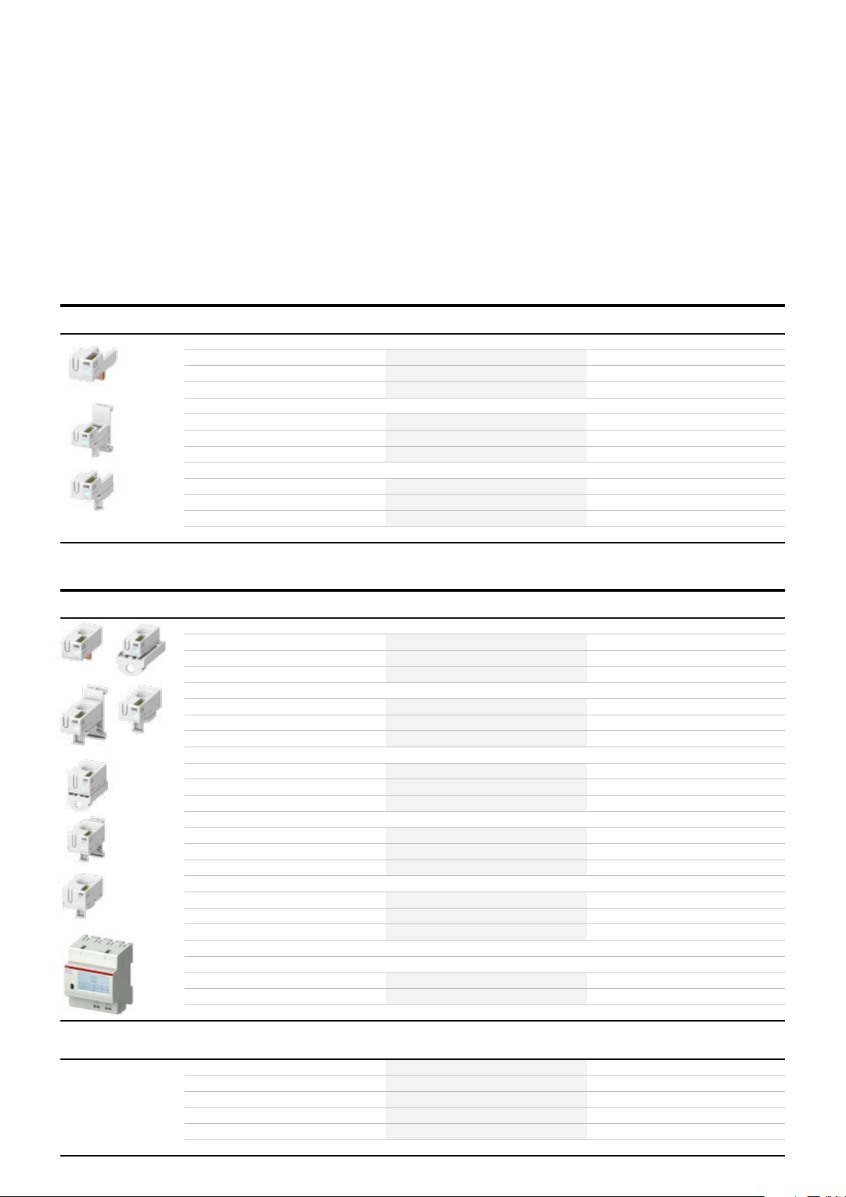
CMS – Circuit Monitoring System
—
Open-core sensors
Description
EAN
Bestelldetails
Artikelnr. Bestellnummer
Weight of
Packaging unit (pce.)
—
Solid-core sensors
Description
EAN
Control units
Bestelldetails
Artikelnr. Bestellnummer
Weight of
Packaging unit (pce.)
—
Accessories
Page 52

—
Approvals according to IEC/EN 61439-6
Busbar system 125 A
—
Power bar system touch proof:
Number of poles
Rated operational voltage (U
Rated insulation voltage (U
IP Code
Mounting position horizontal or vertical, direct mounting or mounting on DIN rail
Pollution degree
Rated impulse voltage (U
Rated current of the assembly (I
Auxiliary circuit
Rated current of a circuit (I
Rated current of Auxiliary circuit
Rated short-time withstand current (I
Auxiliary circuit
Rated peak withstand current (I
Auxiliary circuit
Rated diversity factor (RDF)
Rated frequency (f)
Rated conditional short-circuit current (I
Ambient air temperature
Size of CU auxiliary bars La Lb
)
e
)
i
)
imp
A)
n
)
nc
)
cw
)
pk
)
cc
)
)
51SMISSLINE TP-TOUCH PROOF SYSTEM POWER AND SAFETY
Rated conditional short-circuit
current (I
)
cc
Incoming current of main busbars
Incoming current
of auxiliary busbars (LA LB)
Short circuit protection device
(SCPD)
Fuse MCCB
ABB
T
max
ABB
T
max
ABB
T
max
ABB
ABB
Page 53

52 TECHNICAL CATALOGUE SMISSLINE TP-TOUCH PROOF SYSTEM POWER AND SAFETY
—
Technical data IEC and technical data UL508A
Busbar system 125 A
Maximum rated voltage Maximum rated current Cross-section of conductors
Combi module
LB
LA, LB
SMISSLINE TP system for UL 508 – Industrial Control Equipment,
CSA C22.2 No. 14-13 – Industrial Control Equipment File 20170427-E22211
Technical data UL508 Industrial Control Equipment SMISSLINE TP busbar system
Rated Voltage : 6 00 V AC
Rated Current (End Feed, left and right): 125 A left, 125 A right
Rated Current (Center Feed): 250 A max. if used with two feeder blocks.
Short Circuit Ratings: 50 kA, max. 480 V AC and 480 Y/277 V and 240 V AC or 35 kA, max. 600 V AC and 600 Y/347 V
—
Busbar
Maximum
nominal voltage
Maximum
nominal current
—
Maximum
nominal voltage
Maximum
nominal current
socket
addtional
socket
Feeder
Combimodule
Universaladpter
Termin als
Combi modul
Adapter moter
Page 54

SMISSLINE TP-TOUCH PROOF SYSTEM POWER AND SAFETY
—
Starter pack Touch proof 3L
Busbar system 125 A
—
Solutions
available
Busbars length
incl. Socket
end piece mm
Busbars lengthmmType name ABB IT number EAN
number
Packaging
Weight
in
grams
53
Page 55

54 TECHNICAL CATALOGUE SMISSLINE TP-TOUCH PROOF SYSTEM POWER AND SAFETY
—
Starter pack Touch proof 3LN
Busbar system 125 A
—
Solutions
available
Busbars length
incl. Socket
end piece mm
Busbars lengthmmType name ABB IT number EAN
number
Packaging
Weight
in
grams
Page 56

—
Starter pack Touch proof 3L LA LB
Busbar system 125 A
—
Solutions
available
Busbars length
incl. Socket
end piece mm
Busbars lengthmmType name ABB IT number EAN
number
Packaging
Weight
in
grams
55SMISSLINE TP-TOUCH PROOF SYSTEM POWER AND SAFET Y
Page 57

56 TECHNICAL CATALOGUE SMISSLINE TP-TOUCH PROOF SYSTEM POWER AND SAFETY
—
Starter pack Touch proof 3LN LA LB
Busbar system 125 A
—
Solutions
available
Busbars length
incl. Socket
end piece mm
Busbars lengthmmType name ABB IT
number
EAN
number
Packaging
Weight
in
grams
Page 58

—
Sockets Touch proof
Busbar system 125 A
—
Socket base
Description Typ e
(includes base and cover)
(includes base and cover)
name
ABB
IT number
EAN number
Pack
unit
Moduls
Weight
in
grams
57SMISSLINE TP-TOUCH PROOF SYSTEM POWER AND SAFETY
—
Busbars for the sockets
—
Socket end piece
Description Typ e
Description Typ e
To prevent displacement
of sockets and busbars
name
name
ABB
IT number
ABB
IT number
EAN number
EAN number
Pack-
Module Weight
aging
unit
Pack-
Module
aging
unit
left and
right
in
grams
Page 59

58 TECHNICAL CATALOGUE SMISSLINE TP-TOUCH PROOF SYSTEM POWER AND SAFETY
—
Incoming terminal block and components
—
Incoming terminal block 18 mm, 63 A 2,5 mm
2
to 25 mm2 max. 1 wire
Type name ABB
IT number
EAN
number
Packaging
unit
Module Weight
in
grams
—
Incoming terminal component 10 mm
Version Type name ABB IT number EAN number
Feeder component N
Feeder component N additional socket
Feeder component PE additional socket
Feeder component N additional socket
—
Standard incoming terminal block,
2
to 95 mm
2
(LA, LB)
Type name ABB IT number EAN number
Packaging
unit
Packaging
unit
Module Weight
in
grams
Module Weight
in
grams
Cover for standard incoming terminal block
Additional parts for standard incoming terminal block
(for auxiliary bus bars LA, LB)
N terminal for incom.
–
term. block
Incoming terminal block, low,
Page 60

—
Socket accessories
—
Intermediate piece
light grey, fills shock-proof empty module
Type name ABB IT number EAN number
Packaging
unit
Module Weight
in
grams
59SMISSLINE TP-TOUCH PROOF SYSTEM POWER AND SAFETY
—
Busbar insulator
—
Busbar cover
—
Add-on adapter
—
Mounting rail adapter
for isolation and spacing of separate
electrically protected covering
of main and auxiliary busbars.
Suitable to accept extension adapter
To mount conventional DIN devices
to equalize the installation depth
of standard DIN-rail mounted devices
alongside the SMISSLINE
plug-in system.
—
Locking device
Padlock –
–
Page 61

60 TECHNICAL CATALOGUE SMISSLINE TP-TOUCH PROOF SYSTEM POWER AND SAFETY
—
Universal adapters
IEC 32 A, 63 A, UL489 25 A, 45 A
—
Designation Type name ABB IT number EAN number
N wire top
N wire bottom
Packaging
unit
Module Weight
in
grams
N wire top
N wire bottom
N wire top
N wire bottom
N wire top
N wire bottom
—
—
Accessory
Dummy housing
Connector for multi-pole adapter
Set of
Page 62

—
Additonal socket touch proof
Busbar system 125 A
Additional socket
The additional socket can easily be fitted onto the
socket base to accomodate the external N and/or
PE busbars. This enables neutral connections
to be made where single-pole miniature circuit
breakers are used with unswitched neutral.
—
Additional socket for external N and PE busbars
Type name ABB IT number EAN number
Neutral terminals are clipped onto the ad ditional
socket and can be used as detachable neutral
connections. One N busbar and/or one PE busbar
can be fitted. Each socket base can be equipped
with an additional socket.
Pack-
aging
unit
Module Weight
in
grams
61SMISSLINE TP-TOUCH PROOF SYSTEM POWER AND SAFETY
Page 63

62 TECHNICAL CATALOGUE SMISSLINE TP-TOUCH PROOF SYSTEM POWER AND SAFETY
—
SMISSLINE TP
Terminal range IEC
N terminals and PE terminals
Corresponding N terminals (blue) or PE terminals
(yellow-green) are available for the power
supply and the outgoing conductors of the exter-
nal N and PE busbars for cross sections. The
terminals are fitted with label holders which can
be used with the marking adapter or the marking
label (Phoenix Contact type Clipline UC-TM).
N terminal for additional socket light blue, for external busbars
Type name ABB IT number EAN number
PE terminal for additional socket yellow-green, for external busbars
two holes
Connection for the terminals
2
ZLS912, 915 0,75 mm
up to 10 mm2 litz wire
with ferrule
2
1 mm
2 x 1 ,5 mm
up to 10 mm2 strand
2
or 2 x 2,5 mm2 allowed,
all other combinations it is only
allowed with one wire
2
ZLS91 3, 929 16 mm
up to 35 mm2 wire
with ferrule, max. 1 wire
2
ZLS95 4, 959 50 mm
up to 95 mm2 wire
with ferrule, max. 1 wire
Pack-
aging
unit
Module Weight
in
grams
Red/orange terminals for additional socket
—
Insulator block
The dark grey insulator block isolates the interrupted bus bar ends from one another and simultaneously marks the disconnection point externally.
Insulator block for additional socket
dark gray, to isolate
the N bus bar
on the additional socket
Type name ABB IT number EAN number
Pack-
aging
unit
Module Weight
in
grams
Page 64

—
SMISSLINE TP
Terminal range UL
63SMISSLINE TP-TOUCH PROOF SYSTEM POWER AND SAFET Y
Connection for the terminals
2
ZLS918 UL, 919U L 0,75 mm
up to 10 mm2 litz
wire with ferrule
2
1 mm
2 x 1,5 m m
up to 10 mm2 strand
2
or 2 x 2,5 mm2
allowed, all other com binatins
it is only allowed with one wire
2
ZLS91 3UL, 92 9UL 16 mm
up to 35 mm2 wire
with ferrule, max. 1 wire
2
ZLS95 4UL, 959 UL 50 mm
up to 95 mm2 wire
with ferrule, max. 1 wire
N terminal for additional socket light blue, for external busbars
Type name ABB IT number EAN number
PE terminal for additional socket yellow-green, for external busbars
Packaging
unit
Module Weight
in
grams
—
Insulator block
The dark grey insulator block isolates the interrupted bus bar ends from one another and simultaneously marks the disconnection point externally.
Insulator block for additional socket
dark gray, to isolate
the N bus bar
on the additional socket
Type name ABB IT number EAN number
Packaging
unit
Module Weight
in
grams
Page 65

64 TECHNICAL CATALOGUE SMISSLINE TP-TOUCH PROOF SYSTEM POWER AND SAFETY
—
Busbars 40 A and 125 A
—
Order data
busbar
–
–
–
–
–
–
–
–
–
–
–
–
–
–
–
–
Planning for the incorporation of feeder block and spare places should be taken into account.
The total lengths given above were calculated tak ing socket spac ings and tole rances into account.
For this reason , the indicate d busbar length is not necessarily a multiple of 1 8 mm (1 Module).
ABB
IT number
EAN
number
Module Length
incl.
end piece
Busbar
length
in mm
Order date
busbar
ABB
IT number
EAN
number
Page 66

—
Technical data according to IEC/EN 61439-6
Power Bar System 250 A
—
Busbar system touch proof:
Number of poles:
Rated operational voltage (U
Rated insulation voltage (U
Rated insulation voltage (U
IP Code:
Mounting position: horizontal or vertical, direct mounting or mounting on DIN rail
Pollution degree:
Rated impulse voltage (U
Rated current of the assembly (I
Auxiliary circuit:
Rated current of a circuit (I
Rated current of Auxiliary circuit:
Rated short-time withstand current (I
Auxiliary circuit:
Rated peak withstand current Main circuit (I
Rated peak withstand current Auxilary circuit (I
Rated frequency (f):
Rated conditional short-circuit current (I
Ambient air temperature:
Size of CU auxiliary bars La Lb:
):
e
) Main circuit:
i
) Auxilary circuit:
i
):
imp
A) :
n
) :
nc
):
cw
):
pk
):
pk
): see table below
cc
)
)
65SMISSLINE TP-TOUCH PROOF SYSTEM POWER AND SAFET Y
Rated conditional short-circuit
current (I
cc
Incoming current of main busbars
Incoming current
of auxiliary busbars (LA LB)
Short circuit protection device
(SCPD)
Fuse MCCB
ABB
T
max
ABB
T
max
ABB
Page 67

66 TECHNICAL CATALOGUE SMISSLINE TP-TOUCH PROOF SYSTEM POWER AND SAFETY
—
Starter 3L
Power Bar System 250 A
—
Solutions
available
Type
name
ABB
IT number
EAN number
Pack
unit
Moduls
Weight
in grams
Page 68

—
Starter 3LN
Power Bar System 250 A
—
Solutions
available
Type
name
ABB
IT number
EAN number
Pack
unit
Moduls
Weight
in grams
67SMISSLINE TP-TOUCH PROOF SYSTEM POWER AND SAFETY
Page 69

68 TECHNICAL CATALOGUE SMISSLINE TP-TOUCH PROOF SYSTEM POWER AND SAFETY
—
Starter 3LN LA LB
Power Bar System 250 A
—
Solutions
available
Type
name
ABB
IT number
EAN number
Pack
unit
Moduls
Weight
in grams
Page 70

—
Sockets and Incoming components
Power Bar System 250 A
—
Socket base
Description Type
name
ABB
IT number
EAN number
761 227
Pack
unit
Moduls
(1 PLE
18mm)
69SMISSLINE TP-TOUCH PROOF SYSTEM POWER AND SAFETY
Weight
in
grams
—
Busbars for the sockets
—
Socket end piece
6-module socket
Length 108 mm
(includes base and cover)
8-module socket
Length 144 mm
(includes base and cover)
Description Type
250 A busbar plated,
25 x 3 mm, for L1, L2, L3, N and PE
– Delivery length 1979 mm
40 A auxiliar y busbar plated,
5 x 2 mm, for LA und LB
– Delivery length 1979 mm
Description Type
ZLSP906 2CCF212053A0001 148 7324 10 6 113
ZLSP908 2CCF212052A0001 148 7300 10 8 147
name
ZLSP1250 2CCF212100 M0110 148 8222 1 110 1343
ZLS202 2CCF002773R0001 001 5719 10 110 240
name
ABB
IT number
ABB
IT number
EAN number
761 227
EAN number
761 227
Packaging
unit
Packaging
unit
Module Weight
in
grams
Module Weight
in
grams
To prevent displacement of main
sockets and busbars for the main socket
To prevent displacement of addtional
sockets and busbars addtional socket
—
Incoming terminal component 10 mm2 to 95 mm
Version Ty pe
Feeder component N ZLSP250 2CCV672600R0001 149 0782 1 2 112
Feeder component L1 ZLSP251 2CCV672601R0001 149 0805 1 2 112
Feeder component L2 ZLSP252 2CC V672602R0001 149 0829 1 2 112
Feeder component L3 ZLSP253 2CCV672603R0001 149 0843 1 2 112
Feeder component N additional socket ZLSP954 2CCV672608R0001 149 0867 1 2 10 0
Feeder component PE additional socket ZLSP959 2CCV672609R0001 149 0881 1 2 100
2
, 250 A
ZLSP920 2CCF212082A0001 148 7386 1 2 103
ZLSP921 2CCF212085A0001 148 7409 1 2 54
name
ABB IT number EAN number
761 227
Packaging
unit
Module Weight
in
grams
Page 71

70 TECHNICAL CATALOGUE SMISSLINE TP-TOUCH PROOF SYSTEM POWER AND SAFET Y
—
Additonal socket
Power Bar System 250 A
Additional socket
The additional socket can easily be fitted onto the
socket base to accomodate the external N and/or
PE busbars. This enables neutral connections
to be made where single-pole miniature circuit
breakers are used with unswitched neutral.
—
Additional socket for external N and PE busbars
Type
name
Neutral terminals are clipped onto the ad ditional
socket and can be used as detachable neutral
connections. One N busbar and/or one PE busbar
can be fitted. Each socket base can be equipped
with an additional socket.
ABB IT number EAN number
Packaging
unit
Module Weight
in
grams
—
Busbar insulator
—
Busbar cover
for isolation and spacing of separate
electrically protected covering of main
and auxiliary busbars.
Suitable to accept extension adapter
Type
name
Type
name
ABB IT number EAN number
ABB IT number EAN number
Packaging
unit
Packaging
unit
Module Weight
in
grams
Module Weight
in
grams
This item is need if the additional socket
will be mounted on a DIN rail.
Bag
–
Page 72

—
Table of conteants
Technical data
072 – 080 Busbar system
082 – 094 MCBs technical details
71SMISSLINE TP-TOUCH PROOF SYSTEM POWER AND SAFETY
095 – 102 RCDs technical details
103 IS404 technical details
104 – 105 OVR technical details
106 – 108 Surge and lightning protection
solutions
109 – 110 Auxiliary switches and signal
contacts
111 Shunt trip for S400
112 – 121 CMS – Current Measurement
System
Page 73

72 TECHNICAL CATALOGUE SMISSLINE TP-TOUCH PROOF SYSTEM POWER AND SAFETY
—
Smissline TP technical details
Busbar system 125 A Overview
21
2
1
30
5
3
1 Supply terminal
2 Incoming terminal block with a max. current
rating of 160 A 50 mm
2 x 10 mm
3 Cover for incoming terminal block
4 Supply cable
5 Residual current operated circuit breaker
with overcurrent protection RCBO FS401 and
FS403
6 Residual-current circuit breaker F404
8
4
2
(LA, LB)
6
5
2
(2 x 25 mm2) +
9
12
7
17
10 DIN adapter
11 Spare way cover
12 Device latch
13 Busbar L3 or DC +, –
14 Busbar L2 or DC +, –
15 Busbar L1 or DC +, –
16 Busbar N
17 Cover for socket
18 Sockets
19 Auxiliary busbar LA
7 Miniature circuit breaker S401 M
8 Signal contact
9 Plug contacts
Page 74
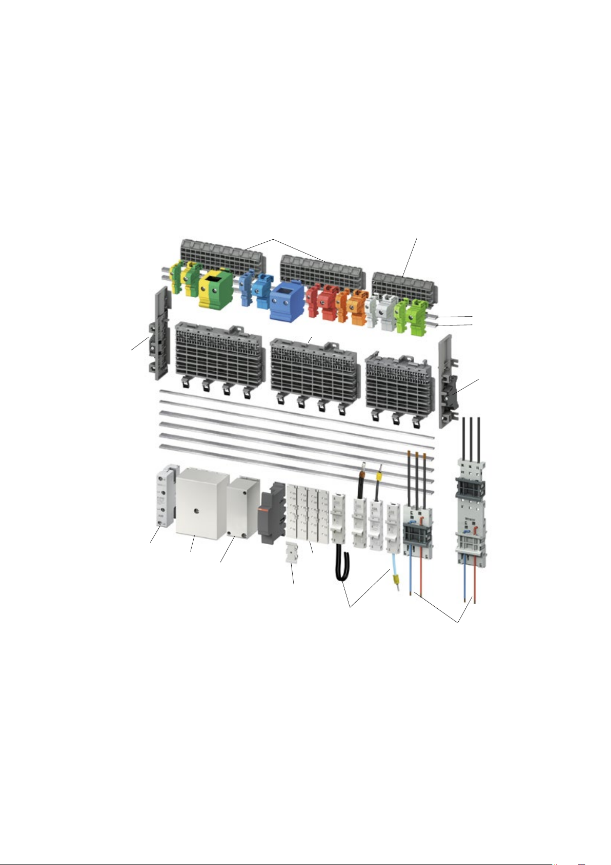
—
Smissline TP technical details
Busbar system 125 A Overview
18
73SMISSLINE TP-TOUCH PROOF SYSTEM POWER AND SAFETY
3027
28
29
23
23
19
20
16
13
14
15
31
32
24
20 Auxiliary busbar LB
21 Output circuits
11
10
26
25
31 Incoming terminal block 63A
32 Incoming terminal block 160A
22 Busbar isolator
23 Socket end piece on left and right
24 Incoming terminal component, centre power
supply 200 A, maximum 95 mm
2
25 Combi module with a current rating of 32 A
26 Adapter for DIN rail components
27 N- and PE Terminals, red and orange
Terminals for d.c. Application
28 Busbar PE, additional socket
29 Busbar N, additional socket
30 Additional socket
Page 75
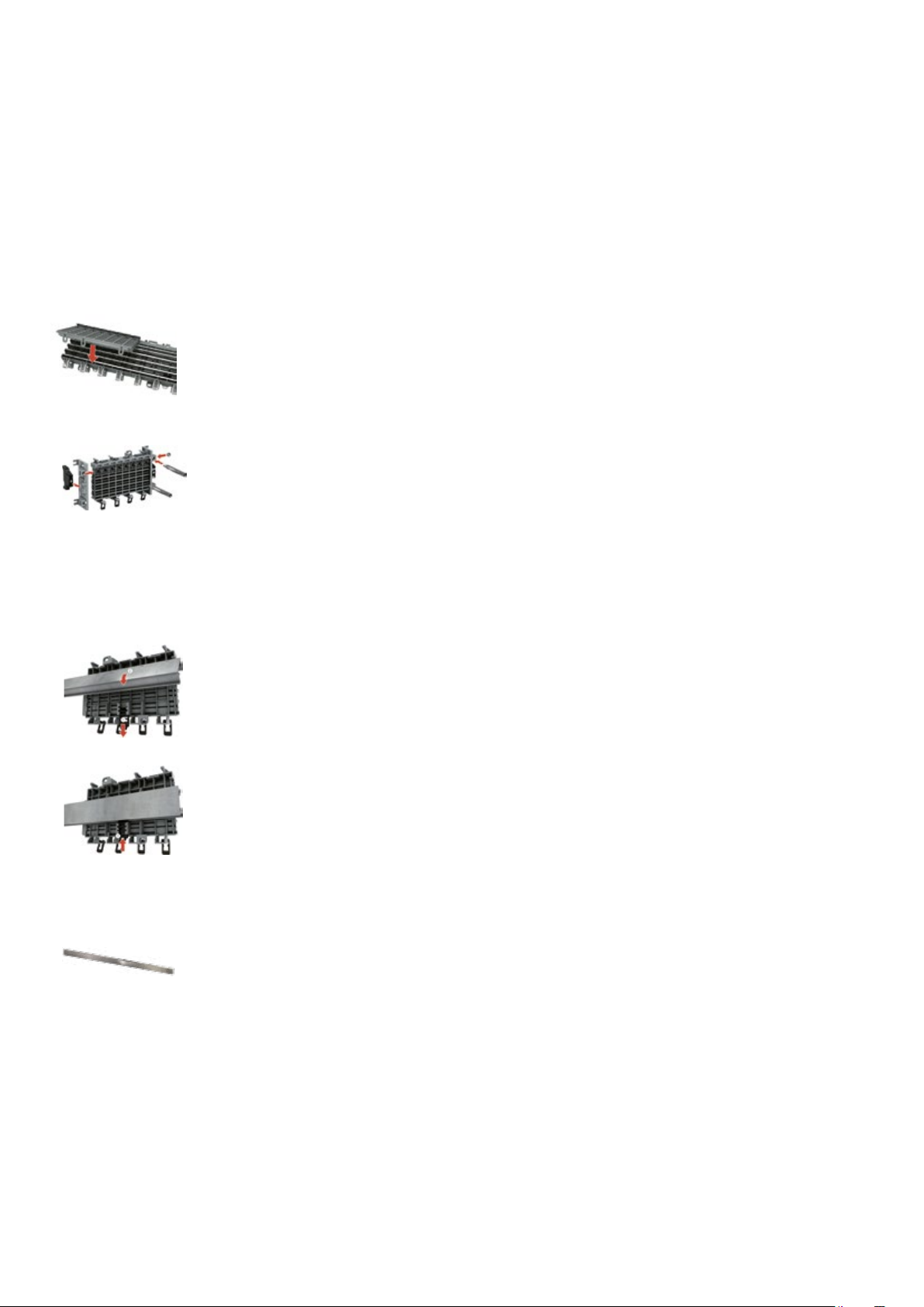
74 TECHNICAL CATALOGUE SMISSLINE TP-TOUCH PROOF SYSTEM POWER AND SAFETY
—
Smissline TP technical details
Busbar system 125 A
Socket bases ZLS906, ZLS908
The smissline socket system is a totally new kind of assembly and connection technology for the construction of distributions. Besides the classic method of snapping the devices onto 35-mm mounting
rails, the new family of devices can be directly attached to the socket bases with integrated busbars.
The time-consuming process of connecting up the supply is thereby no longer needed. In addition, in
the event of rearrangement or expansion, the replacement of devices in existing systems is made significantly easier.
The socket sections and the wide range of accessories make it possible to plan with the capability for
expansion and to construct distribution systems of any desired size in a short period of time.
6- and 8-module sockets are installed either by screwing them onto any flat surface or by snapping
them onto a 35 mm DIN mounting rail. Lateral movement or detachment of the sockets again is possible before final fixing.
- In order to determine the required socket length, the space necessary for
- the devices required
- the incoming terminal block and
- any reserve spaces needed must be determined.
Snap mounting
Pull down the slide with a screwdriver until it latches (socket can be moved).
Press on front of slid:
Fixed position
(Sockets fixed)
The key features
- System of any desired length (even number of poles)
- Integrated busbars
- Simple device change
- Long-term planning and problem free extension possible
- Significant time savings during assembly and connection
Busbars for the sockets and additional socket ZLS200
The busbars of size 10 x 3 mm can be loaded with currents up to 125 A. They are plated for perfect
contact wiith the devices plug-in contacts. The maximum available busbar length is 1979 mm. The same
busbar type is used, regardless whether it is fitted in the socket (L1, L2, L3, N) or in the additional
socket (N, PE). The busbars are inserted in to the socket from the front.
Auxiliary busbars for the socket ZLS202
The 5 x 2 mm auxiliary busbars are intended for a common power supply of auxiliary switches and signal
contacts. They are also plated and their max. delivery length is 1979 mm.
Like the main busbars, the auxiliary busbars are inserted in holders LA and LB from the front. Of course,
only on auxiliary busbar can be fitted.
Page 76

—
Smissline TP technical details
Busbar system 125 A Incoming
Incoming terminal blocks ZLS260 to 262
Compact terminal block with the construction width of 18 mm for 2 poles. The maximum rated current
is 63 A for L1, L2, L3N and 6 A for LA, LB.
General
The incoming terminal block is used to connect cables directly to the busbars. The terminals act
directly on the busbars and therefore fix the incoming terminal block. Removable terminal tops permit
the connection of continous conductrors (risers) white horizontal or vertical cable entry is also
possible.
Instead of using the incoming terminal block, the power supply can also be realized via a device
(e.g. residual current operated circuit breaker, miniature circuit breaker or switch disconnector).
Incoming terminal blocks ZLS224, 225
A standard incoming terminal block whose cover provides protection against accidental contact.
Construction height 50 mm. The base plate can be fitted with a maximum of 4 main terminals L1, L2, L3
and N for the busbars, and 2 auxiliary termiinals LA and LB for the auxiliary busbars.
75SMISSLINE TP-TOUCH PROOF SYSTEM POWER AND SAFETY
Incoming terminal blocks, low ZLS228, 229
Incoming terminal block with construction height of 36 mm.
Feed block left and right
In order to prevent the cables from crossing when two sockets rows are connected it is a good solution
to use a left and a right incoming block (see photo).
Incoming terminal component ZLS250 to 255
The incoming terminal component, with an installation width of 36 mm is available as a single-pole
component for the line conductors L1, L2, L3 and as neutral. The terminals act directly on the busbars
and thereby fix the incoming terminal component. The incoming terminal component, L1, L2, L3 and N
can be combined to meet specific needs. A maximum cable cross-section of 95 mm
to the incoming terminal component.
2
can be connected
Page 77

76 TECHNICAL CATALOGUE SMISSLINE TP-TOUCH PROOF SYSTEM POWER AND SAFET Y
—
Smissline TP technical details
Busbar system 125 A Incoming
—
01 Power supply left or
right, max imum 125 A.
bient air tempe rature
for 125 A continuously)
—
02 Power suppl y left
or right, ma ximum 100 A.
bient air tempe rature
for 125 A continuously)
—
03 Power supply in
centre , maximum 16 0 A.
A maximum of 1 25 A
is permitted o n either
side. A total of 16 0 A
must not be exceeded.
—
04 Incoming
maximum 63 A .
—
05 Inco ming terminal
component, in centre,
max imum 20 0 A.
But on each side not
more than 125 A.
—
01
—
02
—
03
—
05
—
04
Page 78

—
Incoming Power Bar System
250 A and 400 A
—
01 Power supply side
feed, m aximum 25 0 A.
—
02 Central fee d
250A , 400A total.
The cab les in the
connections must have
the same length.
Incoming terminal
blocks ZLP25X.
—
03 Side fe ed maximu m
250 A , 400 A tot al.
The cab les in the
connections must have
the same length.
77SMISSLINE TP-TOUCH PROOF SYSTEM POWER AND SAFETY
—
01
—
02
—
03
Page 79

78 TECHNICAL CATALOGUE SMISSLINE TP-TOUCH PROOF SYSTEM POWER AND SAFETY
—
Technical details
Busbar system power supply
Indirect supply via residual current operated circuit
breaker (RCCB)
(or switch disconnector)
The supply cable is connected at the top of the RCCB. This supply
variant gives the busbars and therefore all subsequent devices RCCB
protection. If several RCCB groups are planned, the busbars should be
separated and spaced using the dark grey busbar insulator ZLS938.
Attention must then be paid to the regulations governing protection of
the residual current circuit breaker by subsequent miniature circuit
breakers. The supply can also be fed in through the switch disconnector.
Direct supply to residual current operated circuit breaker
(or switch disconnector)
Instead of using the incoming terminal block, the power can also be
supplied via a device.
In this case, the supply cable is connected to the lower terminal of the
device. The residual current operated circuit breaker or switch disconnector can be supplied with 63 A regardless of its rated current, since
the plug-in connection arrangement of the device is suitable for this
amount of current.
For current in excess of 63 A, the incoming terminal block or the
incoming terminal component should be used.
Supply of auxiliary busbars LA and LB
The two auxiliary busbars LA and LB can be supplied using the additional terminal ZLS 233 via a incoming terminal block. The maximum
operating current of the auxiliary busbars is 40 A.
Incoming block for two auxiliary busbars LA, LB
The pluggable incoming block is especially for the two auxiliary
busbars LA, LB. The maximum rated current is 6 A.
Page 80

—
Smissline TP technical details
Busbar system 125 A accessories
Socket end piece ZLS920
To prevent displacement of sockets and busbars (particulary when installed vertically) end pieces
can be fitted at the start and finish of each row of sockets. These simultaneously ensure electrically
protected covering of the busbar end faces and mechanical fixing of the sockets oh the mounting rail.
79SMISSLINE TP-TOUCH PROOF SYSTEM POWER AND SAFET Y
Intermediate piece ZLS725
The light grey intermediate piece matches the device profile and fills empty module spaces.
Busbar insulator ZLS938
The dark grey busbar insulator electrically isolates the separated busbar ends from each other
(e.g. when using several RCD protected groups) and also identifies the isolation point from outside.
It conforms with the device profile and its space requirement is 1 module.
Busbar cover ZLS100
If component modules or spare modules are not requiered, the busbar cover ensures electrically
protected covering of the main and auxiliary busbars. The cover (4 modules) can be divided anywhere.
The openings allow voltage measurements on the busbars without removing the cover.
Extension adapter ZLS101
The extension adapter, single or several side by side, can be plugged into the busbar cover via the
built-in holding device. This enables conventional DIN devices with 45 mm cap size to be snapped onto
the SMISSLINE socket. By plugging in several extension adapters one on top of the other, heights can
be adjusted in multiples of 7 mm
Page 81

80 TECHNICAL CATALOGUE SMISSLINE TP-TOUCH PROOF SYSTEM POWER AND SAFETY
—
Definitions
Rated short-circuit breaking capacity I
cn
According to EN 60898-1
The maximum current which a switching device
can switch off without damage at a rated operational voltage and rated operational frequency.
It is specified as an effective value.
Rated ultimate short-circuit breaking
capacity I
cu
According to EN 60947-2
Ultimate short-circuit breaking capacity that a
circuit breaker can switch off without damage at
a rated operational voltage and rated operational
frequency. It is specified as an effective value.
Rated service short-circuit breaking capacity I
cs
According to EN 60947-2
Service short-circuit breaking capacity that a circuit breaker can switch off without damage at a
rated operational voltage and rated operational
frequency. It is specified as an effective value.
Rated insulation voltage U
i
The rated insulation voltage (Ui) is the voltage to
which dielectric checks and creepage distances
refer. The maximum rated operational voltage
must not exceed its rated insulation voltage.
Rated impulse withstand voltage U
imp
Peak of a withstand voltage of a specified form
and polarity with which the circuit can be loaded
under specified test conditions without a breakdown and to which clearances relate.
The rated impulse withstand voltage must be
equal to or greater than the values of the withstand over-voltages (transient overvoltages)
which occur in the system in which the device is
used.
Rated short-time withstand current I
cw
The rated short-time withstand current is the effective value of the short-circuit current, as specified by the manufacturer for this circuit, that the
circuit can conduct without damage. Unless otherwise specified, a time of 1 s shall apply.
Rated conditional short-circuit current I
cc
The rated conditional short-circuit current is the
value of the prospective short-circuit current,
as specified by the manufacturer, for a switching
device combination that the latter can conduct
during the total break time. The information
about the specified short-circuit device must be
given by the manufacturer.
Rated fused short-circuit current I
cf
The rated fused short-circuit current is the conditional rated short-circuit current if the short-circuit device is a fuse in accordance with IEC 60269
[IEV 441-17-21, modified].
Rated peak withstand current I
pk
The rated peak withstand current is the peak
value of the withstand current of the circuit of a
combination of switching devices, as specified
by the manufacturer.
Back-up protection
Assignment of two overcurrent protective
devices in series, where the protective device,
generally but not necessarily on the supply side,
effects the overcurrent protection with or
without the assistance of the other protective
device and prevents excessive stress on the
latter [IEC 60947-1, definition 2.5.24].
Total selectivity
Overcurrent discrimination where, in the presence of two overcurrent protective devices in
series, the protective device on the load side
effects the protection without causing the other
protective device to operate [IEC 60947-2,
definition 2.17.2].
Partial selectivity
Overcurrent discrimination where, in the presence of two overcurrent protective devices in
series, the protective device on
the load side effects the protection up to a given
level of overcurrent, without causing the other
protective device to operate [IEC 60947-2, definition 2.17.3].
Page 82

Multiples of rated current
Multiples of rated current
Seconds Minutes
Tripping curve
from cold state
Seconds Minutes
Tripping curve
from cold state
Multiples of rated current
Seconds
Multiples of rated current
Multiples of rated current
Multiples of rated current
Minutes
Tripping curve
from cold state
Seconds Minutes
Tripping curve
from cold state
Seconds Minutes
Tripping curve
from cold state
Multiples of rated current
Seconds Minutes
Tripping curve
from cold state
—
MCBs technical details
Trip characteristics
81SMISSLINE TP-TOUCH PROOF SYSTEM POWER AND SAFET Y
EN60898 -1
Tripping curve
from cold state
Minutes
Seconds
Multiples of rated current
Trip characteristics: B
Thermal trip
Electromagnetic trip
n
n
n
AC
DC
EN60898 -1 EN60 898-1
Tripping curve
from cold state
Minutes
Seconds
Multiples of rated current
Trip characteristics: C
Thermal trip
Thermal trip
Electromagnetic trip
n
n
AC
n
DC
n
Tripping curve
from cold state
Minutes
Seconds
Trip characteristics: D
Thermal trip
Electromagnetic trip
n
n
n
AC
DC
EN60 947-2
Tripping curve
from cold state
Minutes
Seconds
Multiples of rated current
Trip characteristics: K
Thermal trip
Electromagnetic trip
n
AC
DC
n
n
EN60 947-2
Tripping curve
from cold state
Seconds Minutes
Multiples of rated current
Trip characteristics: UC
Z C
n n DC
n
n AC
n
n
Seconds Minutes
Tripping curve
from cold state
Multiples of rated current
Page 83

30
82 TECHNICAL CATALOGUE SMISSLINE TP-TOUCH PROOF SYSTEM POWER AND SAFETY
—
MCBs technical details
Trip characteristics
I1 = 1,1 3 x In I 2 = 1,45 x I n
Trip characteristics example of trip curve interpretation of
B-characteristics
a Thermal trip characteristics:
Lower test current I
= defined as non-tripping current.
1
The circuit breaker withstands 1.13 times the rated current for
at least 60 minutes.
Upper test current I
= defined as trip current.
2
The circuit breaker trips at 1.45 times the rated current within
60 minutes.
3600
1000
Tripping time in s
100
10
1
5
a
1
1 Limiting
characteristics
from cold status
1
AC
b Electro-magnetic trip characteristics AC:
The circuit breaker withstands 3 times the rated current for
more than 0.1 sec. (in this example, up to around 2 sec.).
The circuit breaker trips in less than 0.1 sec. at 5 times
the rated current.
—
Trip behaviour of different trip characteristics
Thermal release Electromagnetic release
Trip characteristics
and current ratings
B
C
D
K
Test c urrents:
lower
I
n
n
n
x I
n
Application characteristics: B
Miniature circuit breaker for circuits
supplying loads generating no or only
minor inrush currents (boilers, electric
heaters, cookers).
upper
test current
I
n
n
n
n
n
n
Application characteristics: D
Miniature circuit breaker for circuits
supplying loads producing very high
inrush currents (transformers,
ca pacitor banks).
Main circuit breaker for the back-up
Application characteristics: C
The ‘standard’ miniature circuit
protection of downstream connected
circuit breakers.
breaker for circuits supplying loads
producing inrush currents particular to
inductive loads (TV sets, fluorescent
and discharge lamps) and for socket
outlets.
Trip time Test c urrents:
lower
test current
n
n
n
x I
n
Application characteristics: K
Circuit breaker for equipment:
The characteristics of these types enable the close protection requirements
for equipment to be met.
Application characteristics: UC
Device protection in DC systems of up
to 250 V = with a time constant of
<15 ms (emergency networks, electroplating, etc.).
0,1
0,01
1 2 3
upper
test current
n
n
n
n
b
DC
5
Multi ple of rated current
10
Trip time
20
Page 84

—
MCBs technical details
Internal resistances at rated voltage and power losses
—
Internal resistances and power loss per pole (cold resistance at room temperature)
Rated
current
A
I
n
B
PV [W]
C
PV [W]
D
PV [W]
K
PV [W]
83SMISSLINE TP-TOUCH PROOF SYSTEM POWER AND SAFET Y
Rated
current
In A
UCC
PV [W]
UCZ
PV [W]
Page 85
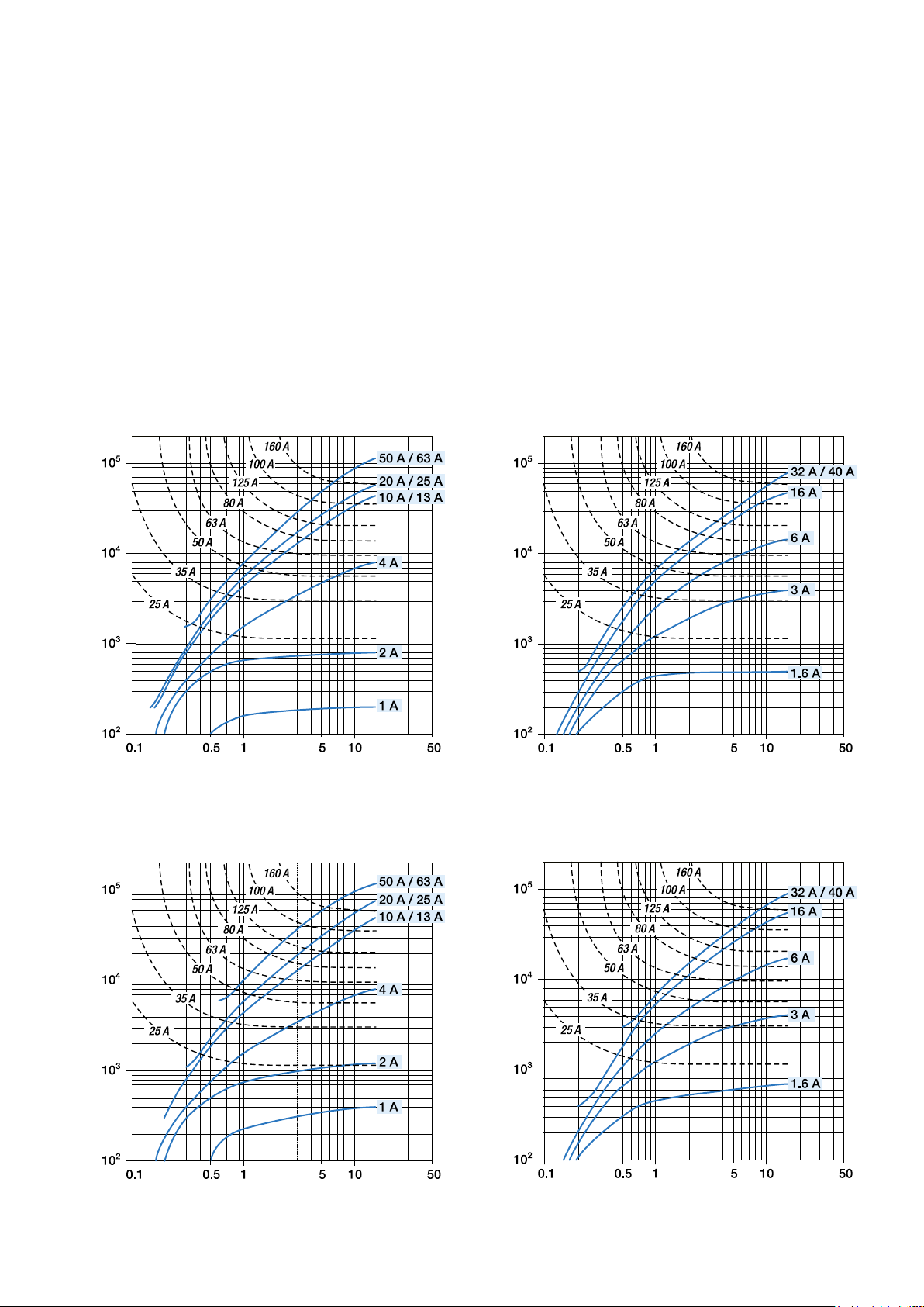
84 TECHNICAL CATALOGUE SMISSLINE TP-TOUCH PROOF SYSTEM POWER AND SAFET Y
Prospective short-circuit current Ik [kA]
let-through energy I
2
t [A
2
s]
let-through energy I
Prospective short-circuit current Ik [kA]
let-through energy I
2
t [A
2
s]
let-through energy I
—
MCBs technical details
Limitation of specific let-through energy I2t
l2t diagrams - Specific let-through energy value l2t
2
t curves give the values of the specific let-through energy expressed in A2s (A=amps; s=seconds) in relation to
The I
the per spective short-circuit current (I
S400 characteristics B–C
) in kA.
rms
s]
2
t [A
2
let-through energy I
S400 characteristics D–K
s]
2
t [A
2
Prospective short-circuit current Ik [kA]
s]
2
t [A
2
s]
2
t [A
2
Prospective short-circuit current Ik [kA]
let-through energy I
Prospective short-circuit current Ik [kA]
Prospective short-circuit current Ik [kA]
Page 86

—
Ip [kA]
Irms [kA]
Ip [kA]
Irms [kA]
MCBs technical details
85SMISSLINE TP-TOUCH PROOF SYSTEM POWER AND SAFET Y
Peak current I
p
Limitation curves – Peak current values
curves give the values of the peak current, expressed in kA, in relation to the perspective symmetrical short-circuit
The I
p
current (kA).
Characteristics B–C
100
50
20
10
5
2
1
0.5
50 63 A
32 40 A
20 25 A
13 16 A
8 10 A
6 A
4 A
3 A
2 A
1,6 A
0,5 1 A
Characteristics K–D
100
0.2
0
0
0.2 0.5 12 5102050 100
50
20
10
5
2
1
0.5
0.2
S400 ES400M
50 63 A
32 40 A
20 25 A
13 16 A
8 10 A
6 A
4 A
3 A
2 A
1,6 A
0,5 1 A
0
0
0.2 0.5 12 5102050 100
S400 ES400 M
Page 87

86 TECHNICAL CATALOGUE SMISSLINE TP-TOUCH PROOF SYSTEM POWER AND SAFETY
—
Power supply:
overload and short-circuit protection
Overload and short-circuit protection of the
plug-in socket system
Protection of the busbar system without
upstream overcurrent protection
An important factor for the protection of the
busbar system (sockets, incoming terminal block,
incoming terminal component, adapter, combi
module or terminals) is the characteristic of the
rated peak withstand current I
withstand current I
system is 35 kA.
Protection of the busbar system with upstream
overcurrent protection
The rated short-circuit current Icf of the
SMISSLINE busbar system is 50 kA.
If, on the power supply side, a circuit breaker of
the type Sace Tmax 200 A, a high performance
circuit breaker S800 or a NH fuse is positioned
upstream of the busbar system, then due to the
short-circuit current limiting effect of this protection device, a larger prospective short-circuit
current of up to 50 kA for the plug-in socket system is permissible.
of the SMISSLINE busbar
pk
. The rated peak
pk
Residual-current circuit breaker
A back-up fuse with max. 100 A gL/gG or a high
performance circuit breaker S800 100 A is
required for short-circuit protection upstream or
downstream (see Coordination table, page 2/42).
A back-up fuse is not required up to the level of
the internal short-circuit withstand rating.
Thermal protection can be ensured by means of
downstream miniature circuit breakers, but only
if the rated currents do not exceed the value of
the current rating of the residual- current circuit
breaker in consideration of a utilisation factor.
Surge arrester OVR
An upstream overcurrent protection device with
max. 160 A gL/gG is necessary for short- circuit
protection (in the case of non-independent interruptions of the secondary current).
Back-up fuses for devices with a universal
adapter
In principle, the same requirements apply as for
directly plugged-in devices.
Overload and short-circuit protection of devices
on the busbar system
The rated short-circuit breaking capacity (or
rated breaking capacity) of the protective
devices, together with the maximum short-circuit
current at the installation location of the devices
on the busbar system, must be taken into consideration.
This is not only relevant for the SMISSLINE busbar
system, but is also applicable to the distribution
construction.
Miniature circuit breaker
If the prospective short-circuit current at the installation location of a miniature circuit breaker is
not greater than its rated breaking capacity, no
back-up protection via an upstream over current
protection device is necessary.
If the prospective short-circuit current at the
installation location of a miniature circuit breaker
is greater than its rated short-circuit breaking
capacity, the current ratings of the upstream
overcurrent protection device must not exceed
the table values in the back-up tables (catalogue,
page 2/20 onwards).
Page 88

—
Back-up and selectivity dates:
Online on ABB webpage SOC
Back-up and selectivity dates
SOC - Selected Optimized Coordination
See as well ABB on https://applications.it.abb.com/SOC/
87SMISSLINE TP-TOUCH PROOF SYSTEM POWER AND SAFET Y
Page 89

88 TECHNICAL CATALOGUE SMISSLINE TP-TOUCH PROOF SYSTEM POWER AND SAFETY
—
MCBs technical details
Back-up protection with fuses, S800
a) If the short-circuit current at the point of installation of the circuit breaker is not greater than the nominal breaking
capacity of the MCB, an upstream fuse is not needed. If a fuse is fitted upstream for installation reasons, any nominal
current may be selected for the fuse.
b) If the short-circuit current at the point of installation of the circuit breaker is greater than its nominal breaking capacity,
the nominal currents of the upstream fuses must not exceed the values specified in the table (back-up protection of
the circuit breaker).
Upstream: Fuse NH..gL/gG
L.
I
cu
[kA]
[kA]
S. NH gL/gG
[kA]
I
[A]
n
I
cn
all
types
I
cn
all
–
types
S.
I
[A]
n
L.
Char. B, C, D, K
I
[kA]
cu
[kA]
I
cn
B, D
E. = Upstream
L. = Dow nstream
Selectivity limits are specified in kA
Char. B, C, D, K
L.
Char. B, C, D
L.
Char. B, C, D
L.
[kA]
I
cu
C, K
I
[kA]
cu
Icn [kA]
B, D
[kA]
I
cn
C, K
S.
In [A]
S.
In [A]
S.
In [A]
Consulting the back-up table
This table provides the value (in kA) for which the back-up protection is ensured between a given combination of circuit
breakers. The table covers possible combinations between the S800 or SACE series Tmax and between SMISSLINE miniature
circuit breakers 400 M.
Page 90

—
MCBs technical details
89SMISSLINE TP-TOUCH PROOF SYSTEM POWER AND SAFET Y
Back-up protection with T
Sace T
Downstream l
Downstream l
max
Version Version B C N N N N S S S H H L V
B, C
C, K
B, D
Version Version B C N S H L V
B, C
C, K
B, D
UpStream
[A] lcu [kA]
n
UpStream
[A] lcu [kA]
n
max
an XT
Supply side
Load side
Char. B, C, D
I
L.
B
Example 1: With a S8 00 nominal current 5 0 A is a Back-up protect ion till a nominal current
of 25 A to a S400 given. The Back- up protecti on ist till 36 kA.
Example 2: Th ere is no Back-up prote ction between supply si de and the load side given.
Back-up protection
The tab les given prov ide the valu e (in kA, re ferring to the break ing capacity) for which the back-up
protec tion among the combination of selected circuit breakers is verified . The tables cover the
possib le combinations bet ween S800 a nd those betwe en the above mention ed circuit breaker s and
the ABB series of mod ular circuit breake rs S400.
The val ues indicate d in the tables refer to th e voltage:
– Vn of 230/400VAC
cu
E.
[kA]
In [A]
Page 91

90 TECHNICAL CATALOGUE SMISSLINE TP-TOUCH PROOF SYSTEM POWER AND SAFETY
OEPM0108
89
1.0
Fm Factor
Number of devices
—
MCBs technical details
Influence of ambient temperature
Allowable current of miniature circuit breakers depending on ambient temperature and max. load current for row
mounted miniature circuit breakers.
Practical procedure
Conditions often arise which allow for simple consideration of the ambient temperature and thermal influences of row
mounted circuit breakers according to EN 60898 and EN 60947-2. The following procedure has proven to be effective:
1. Selection of circuit breaker according to the rated current of the equipment or the current carrying capacity of the
cable depending on whitch of these is the lower value.
2. Consideration of thermal factors
– for an ambient temperature
– for thermal influence of row mounted circuit breakers
3. This results in the rated current of the circuit breaker to be selected for the relevant current
This procedure considers all thermal influence factors and results in an optimum choice of the rated current for the circuit
breaker.
Basis for the simplified procedure
1. Different ambient temperature
For more accurate calculations and very high or very low ambient temperatures, the following tables apply:
2. Influence of row mounted devices at continuous load
If the circuit breakers are lined up close to one another and have equally high load levels, a correction factor must be taken.
This influence can be reduced if fillers and/or spacers (9 mm wide) are used.
—
Influence of adjacent devices S400
0.9
0.8
0.7
0.6
1234567
Influence of adjacent devices
Correction factor Fm
No. of
adjacent devices
correction
factor
Page 92

—
MCBs technical details
Influence of ambient temperature
—
In (A) Ambient temperature T (°C)
91SMISSLINE TP-TOUCH PROOF SYSTEM POWER AND SAFETY
—
In (A) Ambient temperature T (°C)
Page 93

92 TECHNICAL CATALOGUE SMISSLINE TP-TOUCH PROOF SYSTEM POWER AND SAFETY
x
1
2
60 V
()
0 V
x
1
2
x
3
4
125 V
()
0 V
x
1
2
x
3
4
125 V
()
0 V
()
0 V
x
1
2
x
3
4
60 V 60 V
60 V
15
125 V
—
MCBs technical details
Protection of circuits with fluorescent lamps
Protection of circuits with fluorescent lamps
The following table gives the maximum permissible number of fluorescent lamps which can be protected by a single-pole
circuit breaker of characteristic. The figure for multi-pole circuit breakers is reduced by 20%.
Rated current FL not compensated FL compensated in parallel FL with electronic ballast
KVG KVG EVG
1)
E VG: Two-lamp ve rsion, lamps switched togethe r, e lectronic ballast
KVG: Conventional ballast
Use of miniature circuit breakers S400 M for DC systems
A standard miniature circuit breaker type S400 M and S400 E can be used in a DC system by observing the following conditions: Single pole miniature circuit breaker max. 60 V DC. 2-pole miniature circuit breaker with 2-poles in series max. 125 V
DC. The polarity needs not to be taken into account. Load connection can either be at the top or at the bottom of the MCB.
Example of permissible DC voltages depending on the number of poles and the circuit configeration
in earthed DC systems:
x
1
2
x
x
3
1
4
2
x
x
3
1
4
2
x
x
3
1
4
2
0 V
()
Examples for different voltages between a conductor and earth where voltages between conductors are identical:
x
+–
x
3
1
4
2
125 V
+
0 V
()
x
x
3
4
2
125 V
x
x
6
0 V
()
7
8
60 V
60 V
0
()
Page 94

—
L + L –
1
2
3
4
1
L + L –
1
2
3
4
L + L – M
1
2
3
4
1
L + L –
1
2
3
4
L + L – M
1
2
3
4
L + L – M
1
2
3
4
MCBs technical details
S400UC
UC = Universal Current = AC/DC
S400UC MCBs can be used in the one-pole version as 250 V d.c., and in the 2-pole version
with series connection of two poles up to 440 V d.c..
For DC incoming supply from above
S400 UC-... MCBs have, in the area of arc chutes, permanent magnets, it is therefore necessary to take into account the polarity during the installation process.
Doing so ensures that in the case of a short circuit the magnetic field of the permanent magnets corresponds with the electromagnetic field of the short-circuit current, therefore safely
leading the short circuit into the arc chute. Incorrect polarities may cause damage to the
MCB.
This is why – in the case of top-fed devices – terminal 1 must be connected to (–)
and terminal 3 (+).
93SMISSLINE TP-TOUCH PROOF SYSTEM POWER AND SAFETY
—
Example for permissible voltages between the conductors depending
on the number of poles and circuit layout:
voltage U
between
conductors
voltage U
between
conductor and earth
supply
N
N
1
1
2
L + L –
1
3
2
4
L –
L + L –
1
3
2
4
1
1
3
2
4
L + L – M
Page 95
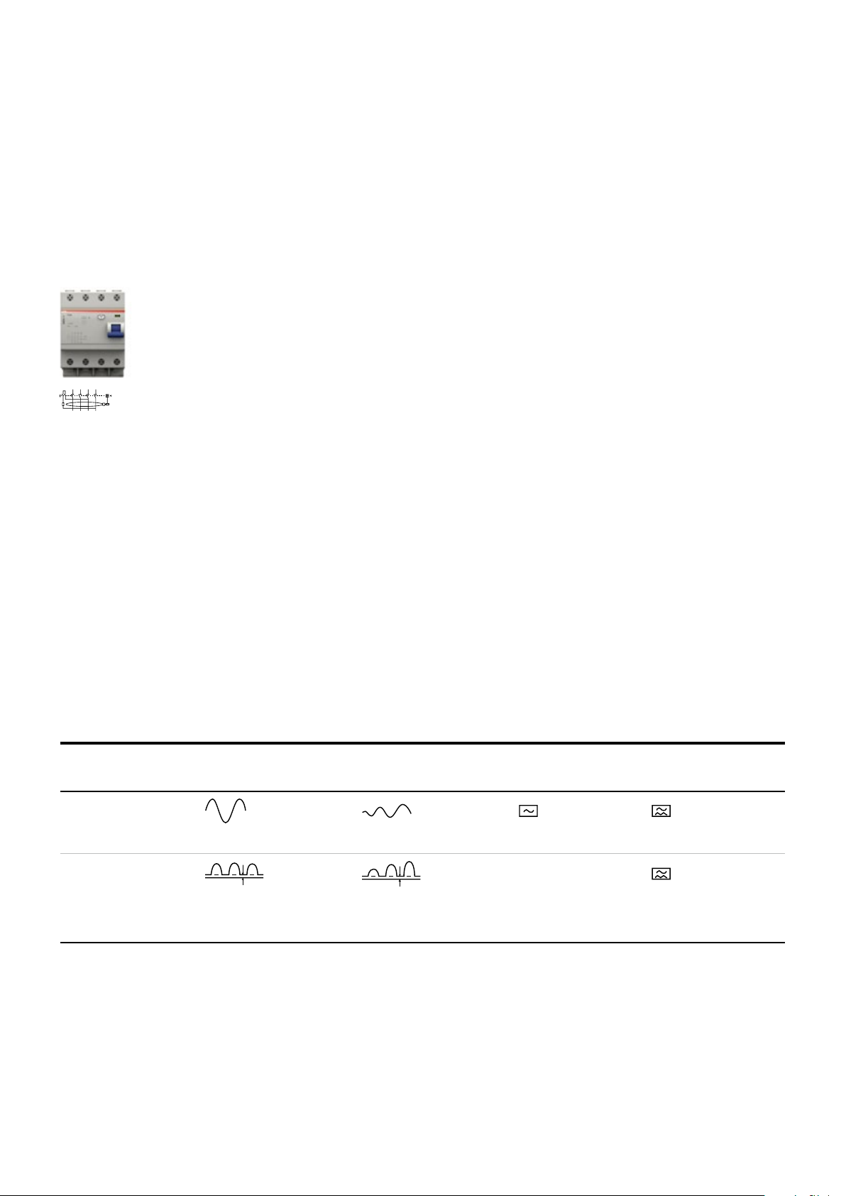
94 TECHNICAL CATALOGUE SMISSLINE TP-TOUCH PROOF SYSTEM POWER AND SAFETY
1/2 3/4
2/1 4/3
5/6 7/8/N
6/5 8/7/N
2CCC404028Z0001
—
RCDs technical details
Properties
General information about residual current operated circuit breakers
The residual current operated circuit breaker prevents personal injury and damage to property caused
by electric current. Use of this circuit breaker is required in various national and international standards
for electrical installations.
Modern residual current operated circuit breakers respond to small residual currents. Interruption
occurs in a fraction of a second even before a hazardous situation for people, animals and property
can arise.
The principle of magnetic tripping independable of the supply voltage ensures perfect and safe
operation even in the event of undervoltage and neutral interruptions.
The key features
- High short-circuit resistance 10 kA
- Sensitive for alternating and pulsating DC residual currents
- 2- and 4-pole types
- Nominal residual trip currents 10, 30, 100, 300 and 500 mA
- Snap-on auxiliary switches and signal contacts
- Nominal currents 25, 40, 63 A
- Double terminals
According to the wave form of the earth leakage currents they are sensitive to,
the RCDs may be classed as:
- A type (for alternating and/or pulsating current with DC components
- AC type (for alternating current only)
ABB SMISSLINE RCD’s are all type A.
Shape of the fault current Correct RDC function
alternating current
Type AC
sinusoidal a.c. rampant slowly rising
pulsating current sensitiv
Type A
pulsating d.c. rampant with or without
overlapping DC components
slowly rising
Selectivity
RCDs raise similar issue to those surrounding the installation of MCBs, and in particular the need
to reduce to a minimum the parts of the system out of order in the event of a fault.
For RCBOs the problem of selectivity in the case of short-circuit currents may be handled
with the same specific criteria as for MCBs.
However, for correct residual current protection, the more important aspects are linked to tripping
times. Protection against contact voltages is only effective if the maximum times indicated
on the safety curve are not exceeded.
Page 96

—
RCDs technical details
Properties
The variety of residual current devices has continuously increased in
last decades following the technology evolution and the massive
introduction of electronics in all fields of applications.
According to the capability to detect different waveforms of residual
current and the relative sophisticated type testing, today the
spectrum of RCDs types covers from pure AC loads up to high
95SMISSLINE TP-TOUCH PROOF SYSTEM POWER AND SAFET Y
frequency and DC related applications with an increasing level of
protection passing from AC types up to F and B types.
Type B
Full type F features.
DC currents.
Type F
Full type A-APR short delay
features.
currents
up to 1 kHz.
Type
AC
A
A-APR
F
B
Type AC
Type A-APR
Full type A features.
Alternating
current only.
Type A
Full type AC features.
with DC components.
Page 97

96 TECHNICAL CATALOGUE SMISSLINE TP-TOUCH PROOF SYSTEM POWER AND SAFETY
Fehlerstrom-Schutzeinrichtungen unterscheiden sich hinsichtlich ihrer Eignung zur Erkennung
verschiedener Fehlerstromformen.
Die unten stehende Tabelle enthält eine Übersicht über die Klassifizierung von RCDs aufgrund
der Wellenform der Ableitströme gegen Erde:
– TypAC, nur wechselstromsensitiv;
– TypA, wechselstrom- und/oder pulsstromsensitiv (mit Gleichstromkomponenten);
– TypA bietet Schutz bei sinusförmigen Wechselfehlerströmen bis zu 1.000Hz sowie bei
pulsierenden und glatten Gleichfehlerströmen.
– TypF mit einer Bemessungsfrequenz von 50Hz oder 60Hz ist für Anlagen konzipiert, die
Frequenzumrichter zwischen Phasenleiter und Neutralleiter oder zwischen Phasenleiter
und geerdetem Mittelleiter enthalten. Schutzeinrichtungen dieses Typs eignen sich für den
Schutz bei sinusförmigen Wechselfehlerströmen mit der entsprechenden Bemessungs-
frequenz, bei pulsierenden Gleichfehlerströmen und bei unter Umständen auftretenden
gemischten Formen.
Wellenform
des
Stroms
Ordnungsgemäße Funktion von Fehlerstrom-
Schutzeinrichtungen des Typs
AuslösestromAC A F B
n n n n
0,5 bis 1,0 IDn
–
n n n
0,35 bis 1,4 IDn
–
n n n
Anschnittwinkel 90°:
0,25 bis 1,4 IDn
–
n n n
Anschnittwinkel 135°:
0,11 bis 1,4 IDn
–
n n n
max. 1,4 IDn + 6m A
– –
n n
max. 1,4 IDn + 10mA
– –
n n
0,5 bis 1,4 IDn
– – –
n
0,5 bis 2,0 IDn
– – –
n
Frequenz 150Hz
0,5 bis 2,4 IDn
– – –
n
Frequenz 40 0Hz
0,5 bis 6 IDn
Fehlerstrom-Schutzeinrichtungen unterscheiden sich hinsichtlich ihrer Eignung zur Erkennung
verschiedener Fehlerstromformen.
Die unten stehende Tabelle enthält eine Übersicht über die Klassifizierung von RCDs aufgrund
der Wellenform der Ableitströme gegen Erde:
– TypAC, nur wechselstromsensitiv;
– TypA, wechselstrom- und/oder pulsstromsensitiv (mit Gleichstromkomponenten);
– TypA bietet Schutz bei sinusförmigen Wechselfehlerströmen bis zu 1.000Hz sowie bei
pulsierenden und glatten Gleichfehlerströmen.
– TypF mit einer Bemessungsfrequenz von 50Hz oder 60Hz ist für Anlagen konzipiert, die
Frequenzumrichter zwischen Phasenleiter und Neutralleiter oder zwischen Phasenleiter
und geerdetem Mittelleiter enthalten. Schutzeinrichtungen dieses Typs eignen sich für den
Schutz bei sinusförmigen Wechselfehlerströmen mit der entsprechenden Bemessungs-
frequenz, bei pulsierenden Gleichfehlerströmen und bei unter Umständen auftretenden
gemischten Formen.
des
Stroms
Ordnungsgemäße Funktion von Fehlerstrom-
Schutzeinrichtungen des Typs
AuslösestromAC A F B
n n n n
0,5 bis 1,0 IDn
–
n n n
0,35 bis 1,4 IDn
–
n n n
Anschnittwinkel 90°:
0,25 bis 1,4 IDn
–
n n n
Anschnittwinkel 135°:
0,11 bis 1,4 IDn
–
n n n
max. 1,4 IDn + 6mA
– –
n n
max. 1,4 IDn + 10mA
– –
n n
0,5 bis 1,4 IDn
– – –
n
0,5 bis 2,0 ID n
Fehlerstrom-Schutzeinrichtungen unterscheiden sich hinsichtlich ihrer Eignung zur Erkennung
verschiedener Fehlerstromformen.
Die unten stehende Tabelle enthält eine Übersicht über die Klassifizierung von RCDs aufgrund
der Wellenform der Ableitströme gegen Erde:
– TypAC, nur wechselstromsensitiv;
– TypA, wechselstrom- und/oder pulsstromsensitiv (mit Gleichstromkomponenten);
– TypA bietet Schutz bei sinusförmigen Wechselfehlerströmen bis zu 1.000Hz sowie bei
pulsierenden und glatten Gleichfehlerströmen.
– TypF mit einer Bemessungsfrequenz von 50Hz oder 60Hz ist für Anlagen konzipiert, die
Frequenzumrichter zwischen Phasenleiter und Neutralleiter oder zwischen Phasenleiter
und geerdetem Mittelleiter enthalten. Schutzeinrichtungen dieses Typs eignen sich für den
Schutz bei sinusförmigen Wechselfehlerströmen mit der entsprechenden Bemessungs-
frequenz, bei pulsierenden Gleichfehlerströmen und bei unter Umständen auftretenden
gemischten Formen.
des
Stroms
Ordnungsgemäße Funktion von Fehlerstrom-
Schutzeinrichtungen des Typs
AuslösestromAC A F B
n n n n
0,5 bis 1,0 IDn
–
n n n
0,35 bis 1,4 IDn
–
n n n
Anschnittwinkel 90°:
0,25 bis 1,4 IDn
–
n n n
Anschnittwinkel 135°:
0,11 bis 1,4 IDn
–
n n n
max. 1,4 IDn + 6mA
– –
n n
max. 1,4 IDn + 10mA
– –
n n
0,5 bis 1,4 IDn
– – –
n
0,5 bis 2,0 ID n
Fehlerstrom-Schutzeinrichtungen unterscheiden sich hinsichtlich ihrer Eignung zur Erkennung
verschiedener Fehlerstromformen.
Die unten stehende Tabelle enthält eine Übersicht über die Klassifizierung von RCDs aufgrund
der Wellenform der Ableitströme gegen Erde:
– TypAC, nur wechselstromsensitiv;
– TypA, wechselstrom- und/oder pulsstromsensitiv (mit Gleichstromkomponenten);
– TypA bietet Schutz bei sinusförmigen Wechselfehlerströmen bis zu 1.000Hz sowie bei
pulsierenden und glatten Gleichfehlerströmen.
– TypF mit einer Bemessungsfrequenz von 50Hz oder 60Hz ist für Anlagen konzipiert, die
Frequenzumrichter zwischen Phasenleiter und Neutralleiter oder zwischen Phasenleiter
und geerdetem Mittelleiter enthalten. Schutzeinrichtungen dieses Typs eignen sich für den
Schutz bei sinusförmigen Wechselfehlerströmen mit der entsprechenden Bemessungs-
frequenz, bei pulsierenden Gleichfehlerströmen und bei unter Umständen auftretenden
gemischten Formen.
des
Stroms
Ordnungsgemäße Funktion von Fehlerstrom-
Schutzeinrichtungen des Typs
AuslösestromAC A F B
n n n n
0,5 bis 1,0 IDn
–
n n n
0,35 bis 1,4 IDn
–
n n n
Anschnittwinkel 90°:
0,25 bis 1,4 IDn
–
n n n
Anschnittwinkel 135°:
0,11 bis 1,4 IDn
–
n n n
max. 1,4 IDn + 6mA
– –
n n
max. 1,4 IDn + 10mA
– –
n n
0,5 bis 1,4 IDn
Fehlerstrom-Schutzeinrichtungen unterscheiden sich hinsichtlich ihrer Eignung zur Erkennung
verschiedener Fehlerstromformen.
Die unten stehende Tabelle enthält eine Übersicht über die Klassifizierung von RCDs aufgrund
der Wellenform der Ableitströme gegen Erde:
– TypAC, nur wechselstromsensitiv;
– TypA, wechselstrom- und/oder pulsstromsensitiv (mit Gleichstromkomponenten);
– TypA bietet Schutz bei sinusförmigen Wechselfehlerströmen bis zu 1.000Hz sowie bei
pulsierenden und glatten Gleichfehlerströmen.
– TypF mit einer Bemessungsfrequenz von 50Hz oder 60Hz ist für Anlagen konzipiert, die
Frequenzumrichter zwischen Phasenleiter und Neutralleiter oder zwischen Phasenleiter
und geerdetem Mittelleiter enthalten. Schutzeinrichtungen dieses Typs eignen sich für den
Schutz bei sinusförmigen Wechselfehlerströmen mit der entsprechenden Bemessungs-
frequenz, bei pulsierenden Gleichfehlerströmen und bei unter Umständen auftretenden
gemischten Formen.
des
Stroms
Ordnungsgemäße Funktion von Fehlerstrom-
Schutzeinrichtungen des Typs
AuslösestromAC A F B
n n n n
0,5 bis 1,0 IDn
–
n n n
0,35 bis 1,4 IDn
–
n n n
Anschnittwinkel 90°:
0,25 bis 1,4 IDn
–
n n n
Anschnittwinkel 135°:
0,11 bis 1,4 IDn
–
n n n
max. 1,4 IDn + 6mA
– –
n n
max. 1,4 IDn + 10mA
– –
n n
0,5 bis 1,4 IDn
Fehlerstrom-Schutzeinrichtungen unterscheiden sich hinsichtlich ihrer Eignung zur Erkennung
verschiedener Fehlerstromformen.
Die unten stehende Tabelle enthält eine Übersicht über die Klassifizierung von RCDs aufgrund
der Wellenform der Ableitströme gegen Erde:
– TypAC, nur wechselstromsensitiv;
– TypA, wechselstrom- und/oder pulsstromsensitiv (mit Gleichstromkomponenten);
– TypA bietet Schutz bei sinusförmigen Wechselfehlerströmen bis zu 1.000Hz sowie bei
pulsierenden und glatten Gleichfehlerströmen.
– TypF mit einer Bemessungsfrequenz von 50Hz oder 60Hz ist für Anlagen konzipiert, die
Frequenzumrichter zwischen Phasenleiter und Neutralleiter oder zwischen Phasenleiter
und geerdetem Mittelleiter enthalten. Schutzeinrichtungen dieses Typs eignen sich für den
Schutz bei sinusförmigen Wechselfehlerströmen mit der entsprechenden Bemessungs-
frequenz, bei pulsierenden Gleichfehlerströmen und bei unter Umständen auftretenden
gemischten Formen.
des
Stroms
Ordnungsgemäße Funktion von Fehlerstrom-
Schutzeinrichtungen des Typs
AuslösestromAC A F B
n n n n
0,5 bis 1,0 IDn
–
n n n
0,35 bis 1,4 IDn
–
n n n
Anschnittwinkel 90°:
0,25 bis 1,4 IDn
–
n n n
Anschnittwinkel 135°:
0,11 bis 1,4 IDn
–
n n n
max. 1,4 IDn + 6mA
– –
n n
max. 1,4 IDn + 10mA
Fehlerstrom-Schutzeinrichtungen unterscheiden sich hinsichtlich ihrer Eignung zur Erkennung
verschiedener Fehlerstromformen.
Die unten stehende Tabelle enthält eine Übersicht über die Klassifizierung von RCDs aufgrund
der Wellenform der Ableitströme gegen Erde:
– TypAC, nur wechselstromsensitiv;
– TypA, wechselstrom- und/oder pulsstromsensitiv (mit Gleichstromkomponenten);
– TypA bietet Schutz bei sinusförmigen Wechselfehlerströmen bis zu 1.000Hz sowie bei
pulsierenden und glatten Gleichfehlerströmen.
– TypF mit einer Bemessungsfrequenz von 50Hz oder 60Hz ist für Anlagen konzipiert, die
Frequenzumrichter zwischen Phasenleiter und Neutralleiter oder zwischen Phasenleiter
und geerdetem Mittelleiter enthalten. Schutzeinrichtungen dieses Typs eignen sich für den
Schutz bei sinusförmigen Wechselfehlerströmen mit der entsprechenden Bemessungs-
frequenz, bei pulsierenden Gleichfehlerströmen und bei unter Umständen auftretenden
gemischten Formen.
des
Stroms
Ordnungsgemäße Funktion von Fehlerstrom-
Schutzeinrichtungen des Typs
AuslösestromAC A F B
n n n n
0,5 bis 1,0 IDn
–
n n n
0,35 bis 1,4 IDn
–
n n n
Anschnittwinkel 90°:
0,25 bis 1,4 IDn
–
n n n
Anschnittwinkel 135°:
0,11 bis 1,4 IDn
–
n n n
max. 1,4 IDn + 6mA
Fehlerstrom-Schutzeinrichtungen unterscheiden sich hinsichtlich ihrer Eignung zur Erkennung
verschiedener Fehlerstromformen.
Die unten stehende Tabelle enthält eine Übersicht über die Klassifizierung von RCDs aufgrund
der Wellenform der Ableitströme gegen Erde:
– TypAC, nur wechselstromsensitiv;
– TypA, wechselstrom- und/oder pulsstromsensitiv (mit Gleichstromkomponenten);
– TypA bietet Schutz bei sinusförmigen Wechselfehlerströmen bis zu 1.000Hz sowie bei
pulsierenden und glatten Gleichfehlerströmen.
– TypF mit einer Bemessungsfrequenz von 50Hz oder 60Hz ist für Anlagen konzipiert, die
Frequenzumrichter zwischen Phasenleiter und Neutralleiter oder zwischen Phasenleiter
und geerdetem Mittelleiter enthalten. Schutzeinrichtungen dieses Typs eignen sich für den
Schutz bei sinusförmigen Wechselfehlerströmen mit der entsprechenden Bemessungs-
frequenz, bei pulsierenden Gleichfehlerströmen und bei unter Umständen auftretenden
gemischten Formen.
des
Stroms
Ordnungsgemäße Funktion von Fehlerstrom-
Schutzeinrichtungen des Typs
AuslösestromAC A F B
n n n n
0,5 bis 1,0 IDn
–
n n n
0,35 bis 1,4 IDn
–
n n n
Anschnittwinkel 90°:
0,25 bis 1,4 IDn
Anschnittwinkel 135°:
Fehlerstrom-Schutzeinrichtungen unterscheiden sich hinsichtlich ihrer Eignung zur Erkennung
verschiedener Fehlerstromformen.
Die unten stehende Tabelle enthält eine Übersicht über die Klassifizierung von RCDs aufgrund
der Wellenform der Ableitströme gegen Erde:
– TypAC, nur wechselstromsensitiv;
– TypA, wechselstrom- und/oder pulsstromsensitiv (mit Gleichstromkomponenten);
– TypA bietet Schutz bei sinusförmigen Wechselfehlerströmen bis zu 1.000Hz sowie bei
pulsierenden und glatten Gleichfehlerströmen.
– TypF mit einer Bemessungsfrequenz von 50Hz oder 60Hz ist für Anlagen konzipiert, die
Frequenzumrichter zwischen Phasenleiter und Neutralleiter oder zwischen Phasenleiter
und geerdetem Mittelleiter enthalten. Schutzeinrichtungen dieses Typs eignen sich für den
Schutz bei sinusförmigen Wechselfehlerströmen mit der entsprechenden Bemessungs-
frequenz, bei pulsierenden Gleichfehlerströmen und bei unter Umständen auftretenden
gemischten Formen.
des
Stroms
Ordnungsgemäße Funktion von Fehlerstrom-
Schutzeinrichtungen des Typs
AuslösestromAC A F B
n n n n
0,5 bis 1,0 IDn
–
n n n
0,35 bis 1,4 IDn
Fehlerstrom-Schutzeinrichtungen unterscheiden sich hinsichtlich ihrer Eignung zur Erkennung
verschiedener Fehlerstromformen.
Die unten stehende Tabelle enthält eine Übersicht über die Klassifizierung von RCDs aufgrund
der Wellenform der Ableitströme gegen Erde:
– TypAC, nur wechselstromsensitiv;
– TypA, wechselstrom- und/oder pulsstromsensitiv (mit Gleichstromkomponenten);
– TypA bietet Schutz bei sinusförmigen Wechselfehlerströmen bis zu 1.000Hz sowie bei
pulsierenden und glatten Gleichfehlerströmen.
– TypF mit einer Bemessungsfrequenz von 50Hz oder 60Hz ist für Anlagen konzipiert, die
Frequenzumrichter zwischen Phasenleiter und Neutralleiter oder zwischen Phasenleiter
und geerdetem Mittelleiter enthalten. Schutzeinrichtungen dieses Typs eignen sich für den
Schutz bei sinusförmigen Wechselfehlerströmen mit der entsprechenden Bemessungs-
frequenz, bei pulsierenden Gleichfehlerströmen und bei unter Umständen auftretenden
gemischten Formen.
des
Stroms
Ordnungsgemäße Funktion von Fehlerstrom-
Schutzeinrichtungen des Typs
AuslösestromAC A F B
n n n n
0,5 bis 1,0 IDn
—
RCDs technical details
Properties
Auslöseströme
Proper functionning of residual current
protective devices of type
RCD type
Type AC Type A Type F Type B
■ ■ ■ ■
–
–
–
– –
– –
– – –
– – –
■ ■ ■
■ ■ ■
■ ■ ■
■ ■
■ ■
■
■
Page 98

—
300 mA
s
30 mA
10 mA
RCDs technical details
Properties
Partial selectivity
97SMISSLINE TP-TOUCH PROOF SYSTEM POWER AND SAFETY
A
B
Total selectivity
Outgoing lines without
person protection
0.5 x I I
I
0.5 x I I
I
dubious
selectivity
safe
selectivity
Protection of comp lete
installation
safe
selectivity
High sensitivity or short time del ayed
resid ual current operated ci rcuit
breaker for person protection
Amperometric (partial) selectivity
Selectivity may be created by placing low-sensitivity RCDs upstream and higher-sensitivity RCDs downstream.
An essential condition which must be satisfied in order to achieve selective co-ordination is that the I
value of the breaker upstream (main breaker) is more than double the I value of the breaker downstream. The operative rule to obtain an amperometric (partial) selectivity is I
of the downstream breaker (e. g.: F404, 300 mA upstream; F402, 100 mA downstream).
= 3 x I
of the upstream breaker
In this case, selectivity is partial and only the downstream breaker trips for earth fault currents
< I < 0,5 x I).
I
Chronometric (total) selectivity
To achieve total selectivity, delayed or selective RCDs must be installed.
The tripping times of the two devices connected in series must be co-ordinated so that the total interruption time t
, for any current value. In this way, the downstream breaker completes its opening before the up-
t
1
of the downstream breaker is less than the upstream breaker’s no-response limit time
2
stream one.
double that of the downstream device in accordance with IEC 64-8/563.3, comments. The operative
rule to obtain an amperometric (partial) selectivity is I
of the upstream breaker = 3 x I of the down-
stream breaker (e. g.: F404, S type, 300 mA upstream).
For safety reasons, the delayed tripping times of the upstream breaker must always be below the
safety curve.
Page 99

98 TECHNICAL CATALOGUE SMISSLINE TP-TOUCH PROOF SYSTEM POWER AND SAFETY
—
RCDs technical details
Standard, short-time delayed and selective type
The use of multiple electronic reactors for the supply of fluorescent lamps instead generates permanent leakage currents and inrush currents that can provoke nuisance tripping of a standard residual
current breaker.
IT system loads and other electronic equipment (e.g. dimmers, computers, inverters) with capacitive
input filters connected between the phases and ground can also generate permanent earth leakage
currents whose sum may provoke the nuisance tripping of a standard residual current breaker.
For these situations, the SHORT-TIME DELAY breakers allow a greater number of devices to be connected to the installation.
Soft-starters for motors are loads which can generate high-frequency capacitive currents (provoked by
the harmonics) toward ground or fed into the network. Also in this case, the use of SHORT-TIME DELAY
residual breakers reduces the sensibility to nuisance tripping.
Compared with standard type breakers, SHORT-TIME DELAY residual current breakers are therefore
characterised, for any given sensibility, by:
- Higher residual trip current
- Tripping time delay
- Better resistance to overvoltages, harmonics and impulse disturbances.
Regulations
The tests set out in the IEC 61008 and IEC 61009 standards verify the resistance of residual current
breakers to unwanted tripping provoked by operation overvoltages, using a ring wave impulse shape of
value of 200 A.
surge test with a 3000 A peak current, but limit the requirement to residual current devices classified
as selective; no test is required for other types.
The ABB range of SHORT-TIME DELAY anti-nuisance tripping breakers and blocks pass the general
of 3000 A prescribed for selective devices.
The F402 K and F404 K should therefore be used to prevent unwanted tripping.
Three different types of Residual current operated circuit breaker
- standard RCD 30 mA
- selective RCD 300 mA
S
- short-time delay RCD 30 mA K
t (s)
0.5
0.3
0.2
0.15
short-time delay 30mA K
0.13
0.10
0.06
0.05
Tripping
0.04
0.01
standard 30mA
selectiv 300mA S
0
22 22 22 100 150 300 600 1500
standard 30mA
selectiv 300mA
I∆n2 x I
∆n
∆n
I
5 x I
∆n
∆n
I
2 x I
∆n
5 x I
∆n
I
(mA)
∆n
-
- The selectiv RCD 300 mA tripp after circa 200 mA and a release time of circa 180 ms.
-
Page 100

—
RCDs technical details
Standard, short-time delayed and selective type
Unwanted tripping
In the event of disturbance in the mains, the RCDs normally present in the system are tripped, breaking
the circuit even in the absence of a true earth fault.
Disturbances of this kind are most often caused by:
- operation overvoltages caused by inserting or removing loads (opening or closing protection of
control devices, starting and stopping motors, switching fluorescent lighting systems on and off,
etc.)
- overvoltages of atmospheric origin, caused by direct or indirect discharges on the electrical line.
Under these circumstances, breaker tripping is unwanted, since it does not satisfy the need to avoid
the risks due to direct and indirect contacts. On the contrary, the sudden and unjustified interruption
of the power supply may result in very serious problems.
99SMISSLINE TP-TOUCH PROOF SYSTEM POWER AND SAFETY
SHORT-TIME DELAY RCDs
The ABB range of SHORT-TIME DELAY anti-disturbance residual current circuitbreakers and blocks was
designed to overcome the problem of unwanted tripping due to overvoltages of atmospheric or operation origin.
The electronic circuit in these devices can distinguish between temporary leakage caused by disturbances on the mains and permanent leakage due to actual faults, only breaking the circuit in the latter
case.
SHORT-TIME DELAY residual current circuit-breakers and blocks have a slight delay into the tripping
time, but this does not compromise the safety limits set by the Standards in force (release time
=150 ms).
at 2 I
Guaranteeing conventional residual current protection, their installation in the electrical circuit therefore allows any unwanted tripping to be avoided in domestic and industrial systems in which service
continuity is essential.
This delay makes the SHORT-TIME DELAY residual current devices especially suited for installations
involving motor starters/variable speed drives, fluorescent lamps or IT/electronic equipment.
—
Table of RDC selectivity
Upstream I
Downstream I
[mA]
inst
inst
inst
inst
S
inst
S
inst = instantaneous S = sele ctive ■ = amperometric (partial) selectivity ■ = chronometric (total) selectivity
[mA]
inst
inst
■ ■ ■ ■ ■
inst
■ ■ ■ ■
inst
■ ■
S
inst
 Loading...