

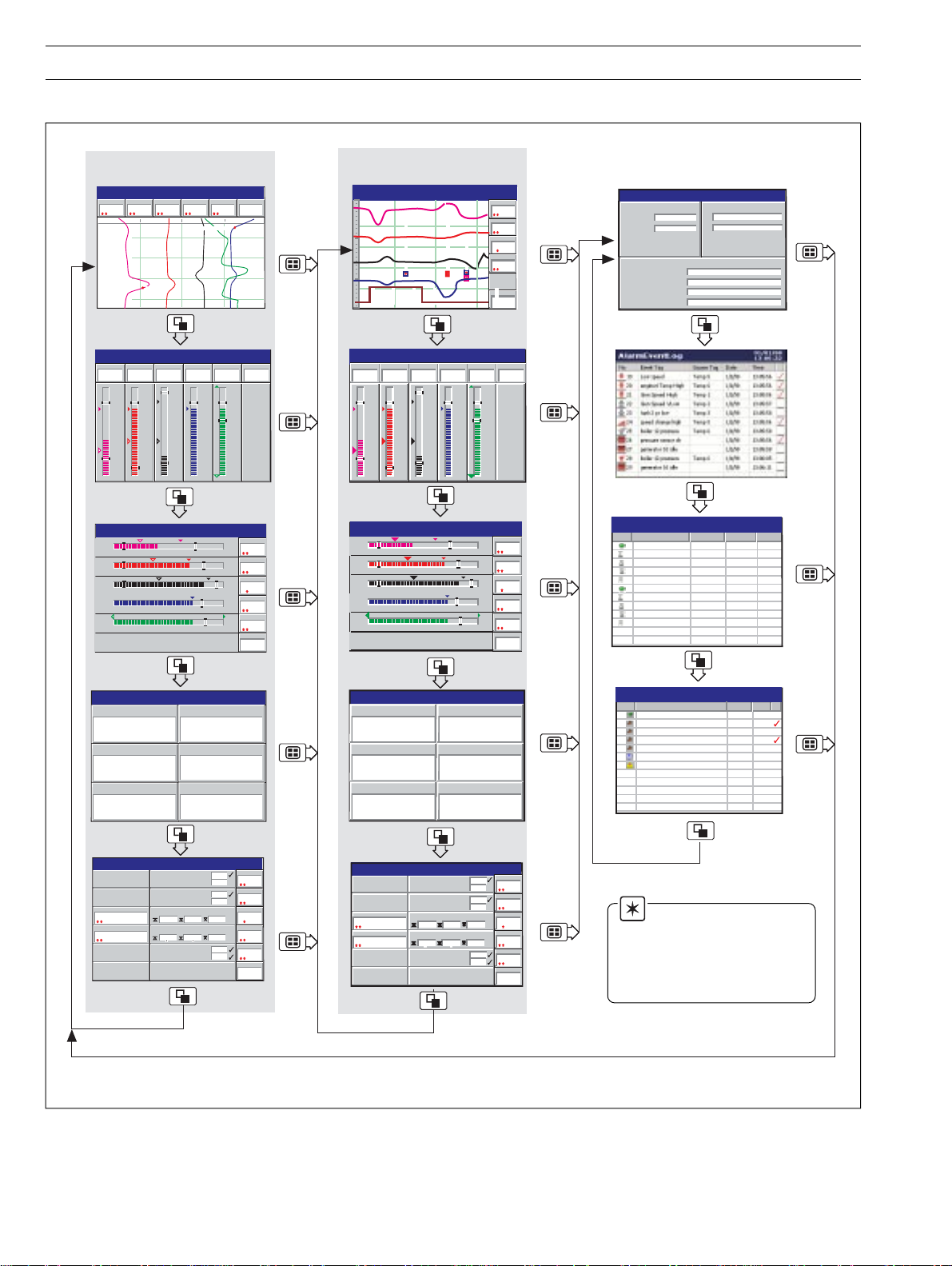
Page 1
Chart
Digital
Bar
Process
Connection
Details
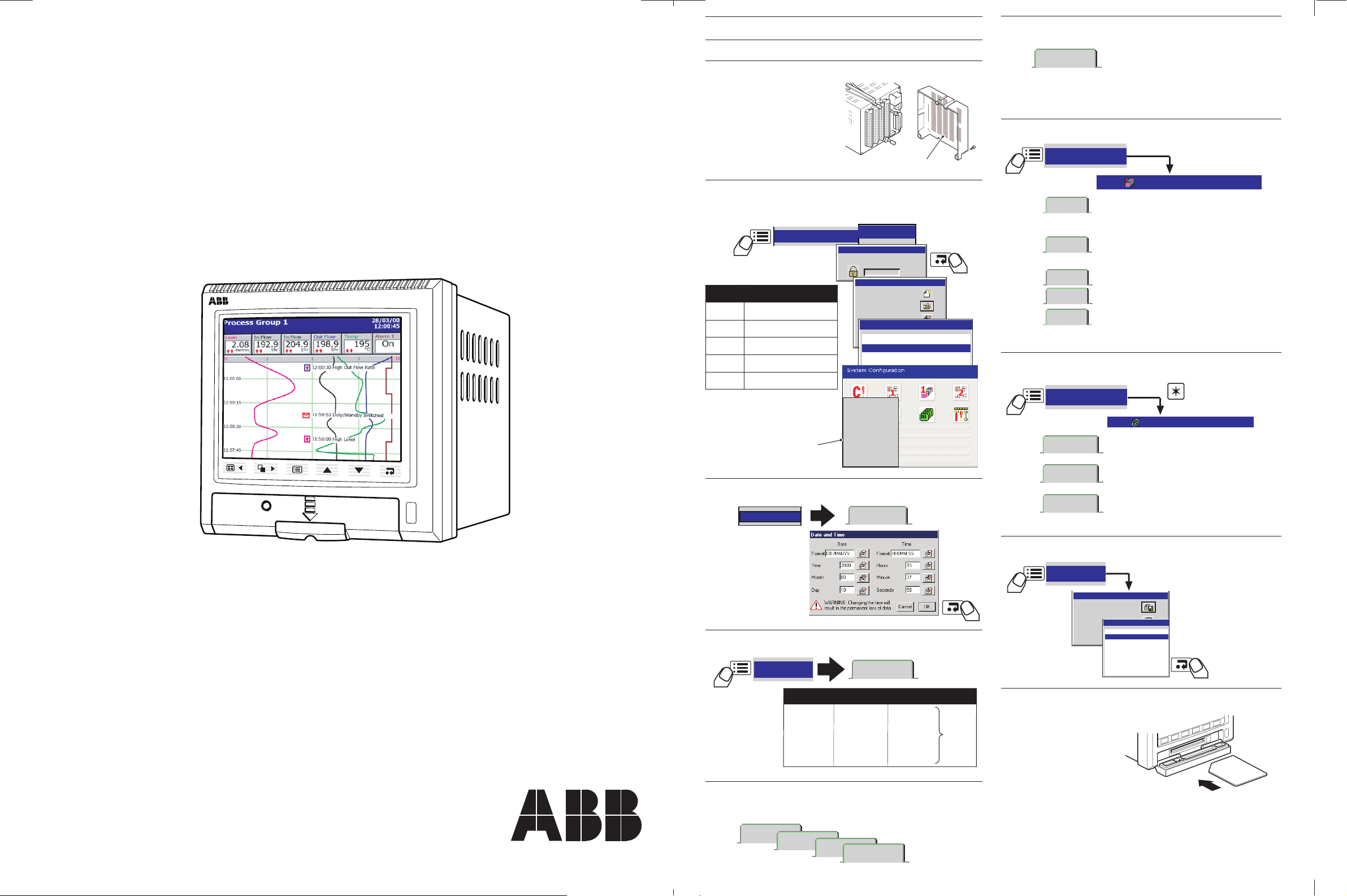
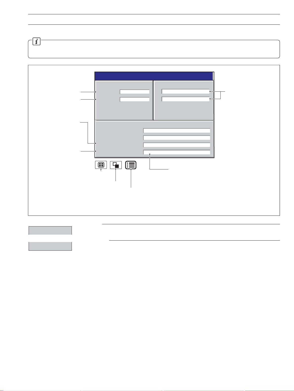
Insert media to start the archiving process automatically
Archive
• Set the Archive File Enables
– i.e. the files to be archived
• Set the Filename Tag
• Set the New File Interval
(hourly, monthly or none)
A:Analog i/p
• Set the Mains Rejection Frequency
• Select the Relay Source and the Relay
Polarity
• Select the Analog Output Source & Ranges
•Select the Digital Output Sources & Polarity
C:Relay
C:Hybrid
Note. Modules fitted
are detected automatically
I/O Modules
I/O Modules
<configuration filename>.cfg
Save as Current Configuration
Save Configuration
Cancel
Exit
<configuration filename>.cfg
Internal Storage
External Storage
Chart speed Sample Rate On board storage
10 mm/h 60s 12 months
20 mm/h 30s 6 months 6
60 mm/h 10s 2 months Channels
120 mm/h 5s 30 days Enabled
240 mm/h 2s 14 days
720 mm/h 1s 6 days
Recording
Group 1
Setup
Common
SM1000
Setup
Analog i/p
Totalizer
• Select the Channel Source
• Set the Input Filter Type: Instantanteous or Max.
and Min. Values during the sample interval.
• Select the input type, linearizer, ranges and
tag name
• Select the Alarm type, set the alarm trip points,
the tag and the hysteresis.
• Set the Count Rate, Preset & Predetermined
Count values
Alarm A
Alarm B
Channel n.n
Channels 1.1 - 1.6
Configuration
Operator 1
Operator 2
Operator 3
Operator 4
Operator 1
Use the up and down keys to select your password.
Confirm with Enter key
0000
Operator 1
New Configuration
Open a Configuration
Edit Existing Configuration
Cancel
Disable Recording During Configuration
Main
Configuration
Menu
5.0
50.2
QSmilliamp
QSFlow
QSTHC_C
QSTHC_F
Configuration File
Common
Group 1
Channels 1.1 - 1.6
Group 2
Channels 2.1 - 2.6
Functions
I/O Modules
Exit
tratSkciuQ
etalpmeT
yrammuS
6.1ot1.1slennahC
pmAilliMSQ
,stupniAm02ot4
stinu0.001ot0
C_CHTSQ
F_CHTSQro
KepytelpuocomrehT
0001ot0 ° 0001ot0roC °F
C_DTRSQ
F_DTRSQro
stupni001tP
0001ot0 ° 0001ot0roC °F
wolFSQ
,rh/l081ot0,Am02ot4
delbanerezilatoT
yriaDSQ
mralAssecorPwoL/hgiHdeyaleD
09ot01–egnaRgnireenignE °C
User Guide
SM1000 QUICK START GUIDE
Set Up the Archive Files
6
Videographic Recorder
SM1000
Make Connections
1
& Power-up the
Instrument
Select the Configuration Level
2
and a Quick Start Template
Change the Channel Configurations
7
Set Up I/O
8
Set the Time and Date
3
Set the Sample Rate
4
Select the Views Required
5
and the Operator Menu Choices
Exit Configuration and Save Changes
9
Start Recording!
10
Page 2
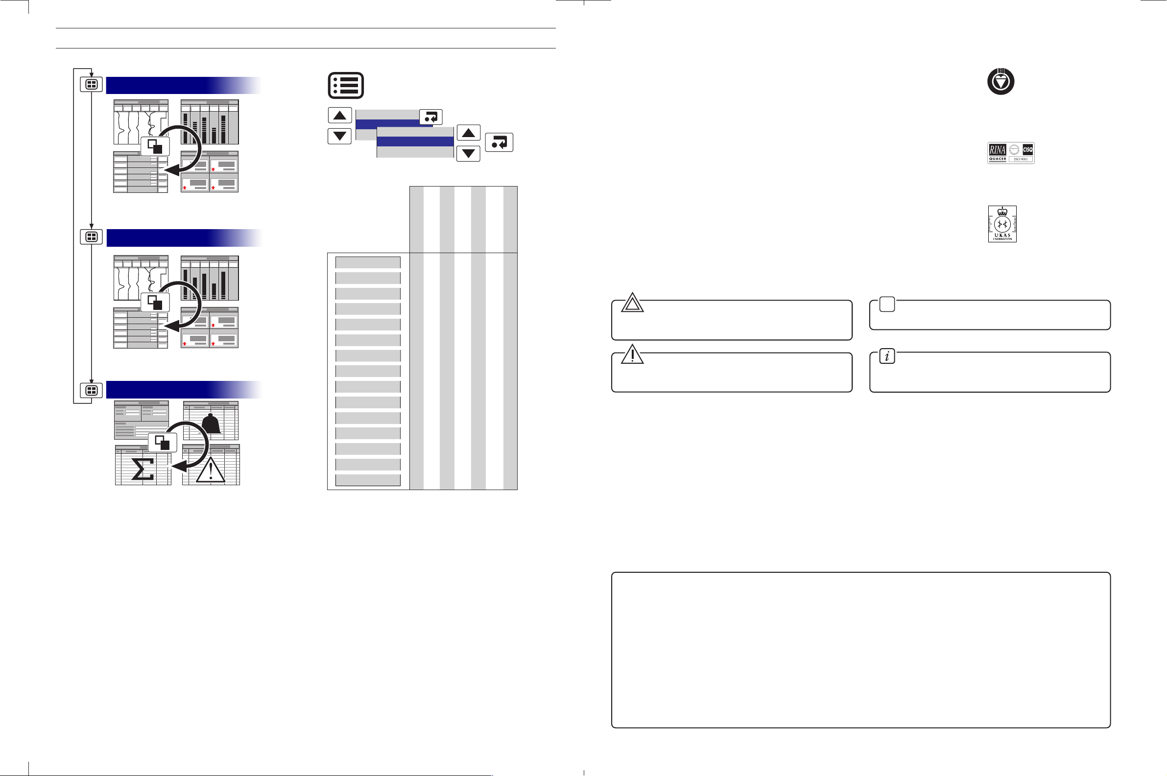
Setup
Operator messages
Alarm acknowledge
Process Tune
Standby Switched
Day Shift
Chart View
Bar View
Indicator View
Process View
Alarm Event Log
Totalizer Log
Audit Log
Configuration
Set up
Historical review
View select
Operator messages
Chart annotation
Screen interval
Scales
Trace select
Channel select
Max/Min reset
Totalizer stop/Go
Totalizer reset
Filter
Alarm acknowledge
✔✔ ✔ ✔ ✔✔ ✔
✔✔ ✔ ✔ ✔✔ ✔
✔
✔
✔✔ ✔ ✔
✔
✔
✔
✔
✔
✔✔
✔✔
✔✔
✔✔
✔✔ ✔ ✔ ✔✔ ✔
Process Group 1
Process Group 2
Logs
Operator Functions
R
E
G
I
S
T
E
R
E
D
0255
ABB
The Company
We are an established world force in the design and manufacture of instrumentation for
industrial process control, flow measurement, gas and liquid analysis and environmental
applications.
As a part of ABB, a world leader in process automation technology, we offer customers
application expertise, service and support worldwide.
We are committed to teamwork, high quality manufacturing, advanced technology and
unrivalled service and support.
The quality, accuracy and performance of the Company’s products result from over 100 years
experience, combined with a continuous program of innovative design and development to
incorporate the latest technology.
The NAMAS Calibration Laboratory No. 0255 is just one of the ten flow calibration plants
operated by the Company, and is indicative of our dedication to quality
and accuracy.
Use of Instructions
Warning.
An instruction that draws attention to the risk of injury or
death.
✶
Note.
Clarification of an instruction or additional information.
BS EN ISO 9001
Cert. No. Q5907
EN 29001 (ISO 9001)
Lenno, Italy – Cert. No. 9/90A
Stonehouse, U.K.
Caution.
An instruction that draws attention to the risk of damage to
the product, process or surroundings.
Although
Warning hazards are related to personal injury, and Caution hazards are associated with equipment or property damage,
Information.
Further reference for more detailed information or
technical details.
it must be understood that operation of damaged equipment could, under certain operational conditions, result in degraded
process system performance leading to personal injury or death. Therefore, comply fully with all
Warning and Caution notices.
Information in this manual is intended only to assist our customers in the efficient operation of our equipment. Use of this manual
for any other purpose is specifically prohibited and its contents are not to be reproduced in full or part without prior approval of the
Marketing Communications Department.
Health and Safety
To ensure that our products are safe and without risk to health, the following points must be noted:
1. The relevant sections of these instructions must be read carefully before proceeding.
2. Warning labels on containers and packages must be observed.
3. Installation, operation, maintenance and servicing must only be carried out by suitably trained personnel and in accordance with the
information given.
4. Normal safety precautions must be taken to avoid the possibility of an accident occurring when operating in conditions of high pressure
and/or temperature.
5. Chemicals must be stored away from heat, protected from temperature extremes and powders kept dry. Normal safe handling procedures
must be used.
6. When disposing of chemicals ensure that no two chemicals are mixed.
Safety advice concerning the use of the equipment described in this manual or any relevant hazard data sheets (where applicable) may be
obtained from the Company address on the back cover, together with servicing and spares information.
Page 3

CONTENTS
1 INTRODUCTION .............................................................. 2
2 OPERATION .....................................................................3
2.1 Powering Up the Instrument .............................................. 3
2.2 Displays and Controls ....................................................... 3
2.3 Chart Views (Horizontal and Vertical) ................................. 4
2.4 Bargraph Views (Horizontal and Vertical).......................... 10
2.5 Digital Indicator View ....................................................... 12
2.6 Process View .................................................................. 14
2.7 Alarm Event Log .............................................................. 16
2.8 Totalizer Log .................................................................... 18
2.9 Audit Log ........................................................................ 20
2.10 Status View ..................................................................... 21
3 SETUP............................................................................ 22
3.1 Introduction ..................................................................... 22
3.2 Accessing the Setup Level .............................................. 22
3.3 Setup Menu .................................................................... 23
3.4 Archiving ......................................................................... 25
3.4.1 SmartMedia Handling and Care .......................... 25
3.4.2 Media Status ...................................................... 25
3.4.3 Inserting and Removing Media ........................... 26
3.4.4 Archive File Types ............................................... 27
3.4.5 Channel Data Files .............................................. 27
3.4.6 Filename Example .............................................. 27
3.4.7 Log files .............................................................. 27
3.4.8 Online/Offline ...................................................... 27
3.4.9 Archiving Updates .............................................. 28
3.4.10 File Formats ........................................................ 28
3.4.11 Digital Signatures ................................................ 28
4 CONFIGURATION.......................................................... 30
4.1 Introduction ..................................................................... 30
4.1.1 Configuration Method ......................................... 30
4.1.2 Configuration Access ......................................... 30
4.2 Overview of Configuration ............................................... 32
4.2.1 Adjusting Screen Contrast .................................. 33
4.3 Making Changes to Parameters ...................................... 33
4.4 Common Configuration ................................................... 36
4.4.1 Setup ................................................................. 36
4.4.2 Security .............................................................. 37
4.4.3 Logs ................................................................... 38
4.4.4 Operator Messages ............................................ 38
4.5 Process Group Configuration .......................................... 39
4.5.1 Setting the Recording Parameters ...................... 39
4.5.2 Configuring the Chart Display ............................. 41
4.5.3 Configuring the Bargraph display ........................ 43
4.5.4 Configuring the Process View ............................. 44
4.5.5 Digital Indicator View .......................................... 45
4.5.6 Archiving ............................................................ 46
4.6 Channel Configuration ..................................................... 49
4.6.1 Recording Channel Setup ................................... 50
4.6.2 Analog Input Configuration ................................. 52
4.6.3 Digital Input Configuration ................................... 54
4.6.4 Alarm Configuration ............................................ 55
4.6.5 Totalizer Configuration ........................................ 60
4.7 I/O Module Configuration ................................................ 63
4.7.1 Analog Inputs ..................................................... 63
4.7.2 6-Relay Modules ................................................ 64
4.7.3 Hybrid Modules .................................................. 64
4.7.4 RS485 Modules .................................................. 65
4.7.5 Ethernet Modules ............................................... 66
4.8 Functions ........................................................................ 67
4.8.1 Custom Linearizers ............................................. 67
4.8.2 Real Time Alarms ............................................... 68
5INSTALLATION .............................................................. 69
5.1 Siting............................................................................... 69
5.2 Mounting ......................................................................... 70
5.3 Electrical Connections ..................................................... 71
5.4 Analog Inputs .................................................................. 72
5.5 RS422/485 Serial Communications ................................. 73
5.6 Mains Power Connections............................................... 74
5.7 Relay Output Board Connections .................................... 74
5.8 Hybrid I/O Module Connections ...................................... 74
5.8.1 Digital Output Connections ................................. 74
5.8.2 Digital Input Connections .................................... 74
5.8.3 Analog Output Connections ............................... 74
APPENDIX 1 – SIGNAL SOURCES ....................................75
APPENDIX 2 – MODBUS GUIDE ....................................... 76
A2.1 Introduction ..................................................................... 76
A2.2 Setting Up ....................................................................... 76
A2.3 Modbus Commands Supported ...................................... 76
A2.4 Modbus Exception Responses ........................................ 76
A2.5 Operating Mode Modbus Coils ........................................ 76
A2.6 Operating Mode Modbus Registers ................................. 79
A2.7 Comms Analog and Digital Inputs ................................... 81
APPENDIX 3 – STORAGE CAPACITY ................................ 81
A3.1 Internal Storage Capacity ................................................ 81
A3.2 Archive Storage Capacity ................................................ 82
APPENDIX 4 – DEFAULT SETTINGS .................................83
A4.1 Company Standard ......................................................... 83
A4.1.1 Common Configuration ...................................... 83
A4.1.2 Process Groups 1 and 2 ..................................... 83
A4.1.3 Recording Channels ........................................... 83
A4.1.4 I/O Modules........................................................ 84
A4.2 QuickStart Templates ...................................................... 84
A4.2.1 QSMilliAmp......................................................... 84
A4.2.2 QSFlow .............................................................. 84
A4.2.3 QSTHC_C .......................................................... 85
A4.2.4 QSTHC_F........................................................... 85
A4.2.5 QSRTD_C .......................................................... 85
A4.2.6 QSRTD_F ........................................................... 85
A4.2.7 QSDEMO ........................................................... 85
A4.2.8 QSDAIRY ........................................................... 85
APPENDIX 5 – SPARE PARTS & ACCESSORIES ............. 87
APPENDIX 6 – ERROR & DIAGNOSTICS INFORMATION 88
INDEX ..................................................................................89
Note.
For optional accessories, refer to
APPENDIX 5.
Keys
Mounting Clamps
Shunt Resistors
(1 per analog input)
Standard Accessories
1
Page 4
1 INTRODUCTION
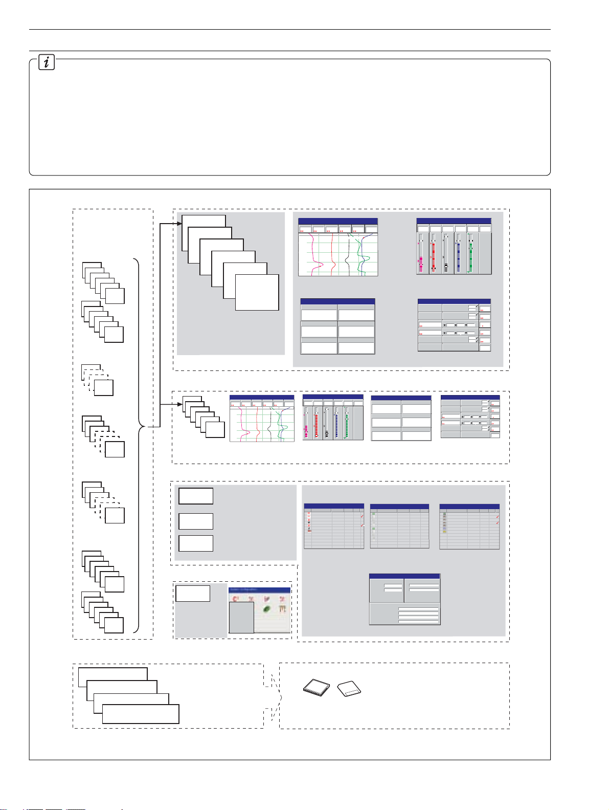
Functional Overview – Fig. 1.1.
• 12 Recording Channels as standard, divided into 2
Process Groups, each with 6 Recording Channels.
•Two Alarms and one Totalizer are assigned to each
Recording Channel.
• Recording Channels 1.1 to 1.6 pre-assigned to Process
Group 1. Recording Channels 2.1 to 2.6 pre-assigned to
Process Group 2.
Sources
Note. Sources can be
assigned to any
recording channel in
either process group.
Analog Inputs
A1
A2
A3
A4
A5
A6
B1
B2
B3
B4
B5
B6
Internal sources –
see Appendix 1
Process Group 1
1.1
1.2
1.3
1.4
1.5
•Two process groups as
standard provide 12 recording
channels, irrespective of the
number of external inputs.
Recording
Channels
1.1 to 1.6
1.6
• Recording sources derived from universal analog inputs,
the Modbus serial link, optional digital inputs or internal
analog and digital signals.
• Any source can be assigned to any recording channel.
• Data from assigned sources can be displayed in Chart,
Bargraph, Indicator and Process formats.
• Three instrument logs record alarm events, totalizer
values and system/configuration changes.
Chart View
In Flow
Pressure
Level
204.9
4
2.08
bar
metres
010
12:00:00
11:59:00
11:58:00
High Level
11:57:00
28/03/00
14:52:00
Alarm 1
Temp
Out Flow
On
195
198.9
°C
l/hr
l/hr
High Out Flow Rate
Chart View (Section 2.3)
Digital Indicator
LevelLevel
2.08
In Flow
204.4
0005402801
Temp
195
Pressure
Out Flow
198.4
Alarm 1
4
0005402060
On
28/03
/00
Digital Indicator View (Section 2.5)
Vertical Bargraph
In Flow
Pressure
Level
204.9
4
2.08
bar
metres
5.0
5.0
300
2.5
2.5
150
0.0
0.0
0
Bargraph View (Section 2.4)
Process View
Tank 1 Low Level
Tank 1 High Level
Tank 1 Low Pressure
Tank 1 High Pressure
Total Daily In Flow
Storage Tank 1 In Flow
00054
225.4 110.9 201.0
02801
Total Daily Out Flow
litres
Storage Tank 1 Out Flow
00054
229.1 100.1 200.9
02060
litres
Tank 1 Low Temp
Tank 1 High Temp
Process View (Section 2.6)
28/03/00
14:52:00
Alarm 1
Temp
Out Flow
On
195
198.9
°C
l/hr
l/hr
300
250
150
125
0.0
0
28/03/
00
Level
1.2
2.0
4.
8
Press
metres
0.2
4
4.
bar
In
20
4.9
Out
l/hr
19
8.9
Temp
l/hr
15
19
25
5
Alarm
°C
On
Comms
Analog Inputs
1
2
3
24
Comms
Digital Inputs
1
2
3
24
Digital Inputs
C1
C2
C3
C4
C5
C6
D1
D2
D3
D4
D5
D6
Recorded Data
Recording Channels 1.1 to 1.6
(Process Group 1)
Recording Channels 2.1 to 2.6
(Process Group 2)
Instrument Logs
Configuration Data
Process Group 2
2.1
2.2
2.3
2.4
2.5
2.6
Recording
Channels
2.1 to 2.6
Instrument Logs
Alarm/Event Log
Totalizer Log
Audit Log
*if option fitted
Configuration Data
Configuration
Data
Stores all
instrument
configuration,
calibration and
user preferences
Files stored in instrument's
on-board flash memory.
Newest data overwrites
oldest.
28/03/00
Chart View
Pressure
Level
2.08
metres
010
12:00:00
11:59:00
11:58:00
11:57:00
Temp
Out Flow
In Flow
198.9
204.9
4
l/hr
l/hr
bar
High Out Flow Rate
High Level
Chart View
Records all alarm
transistions and all
operator messages
Records all totalizer
activity*
Records all system
acfivity
Common
Group 1
Channels 1.1 - 1.6
Group 2
Channels 2.1 - 2.6
Functions
I/O Modules
Exit
14:52:00
Alarm 1
On
195
°C
Vertical Bargraph
Level
2.08
metres
5.0
2.5
0.0
Bargraph View
Alarm Event Log
(Section 2.7)
Alarm Event Log
00 Tank 1 High Level Level 28/08/00 14:01
01 Tank 1 High Level Level 28/08/00 14:03
02 High Out Flow Rate Out Flow 28/08/00 14:09
03 Tank 1 High Level Level 28/08/00 14:11
04 High Out Flow Rate Out Flow 28/08/00 14:12
05 High Out Flow Rate Out Flow 28/08/00 14:15
06 Duty/Standby Change Out Flow 28/08/00 14:31
Archive Data
Pressure
204.9
4
bar
5.0
2.5
0.0
On
195
198.9
°C
l/hr
l/hr
300
300
250
150
150
125
0
0.0
0
LevelLevel
In Flow
Temp
2.08
204.4
0005402801
195
Pressure
Out Flow
Alarm 1
198.4
0005402060
On
4
28/03/00
14:52:00
Digital Indicator
Alarm 1
Temp
Out Flow
In Flow
Digital Indicator View
To ta lizer Log
(Section 2.8)
28/03/00
Totalizer Log
14:52:00
No Tag/Value Source Tag Date Time
Total Daily In Flow In Flow 28/03/00 14:52
0005402801 Litres
225.4 l/hr
110.9 l/hr
201.0 l/hr
Total Daily Out Flow Out Flow 28/03/00 14:52
0005402060 Litres
229.1 l/hr
100.1 l/hr
200.9 l/hr
•Views provide a window on the stored data.
Status View
VERSION
Software
System
ARCHIVING
Group 1 Filename
Group 2 Filename
% Memory used
Time left
SM 2001/1
1.0.130
Process Group 1
Process Group 2
80.5%
5 days
CJ TEMPERATURES
25°C / 77°F
A
25°C / 77°F
B
• Status View
Data saved to archive storage media
Archive Media
28/03
/00
Audit Log
(Section 2.9)
28/03/00
Audit Log
14:52:00
No Alarm Event Tag Source Tag Date Time
00 Power Restored 25/03/00 11:59
01 I/O Configuration JM 25/03/00 12:01
02 Common Configuration JM 25/03/00 12:05
03 Group 1 Configuration JM 25/03/00 12:09
04 Ch1.1 to 6 Config JM 25/03/00 12:10
05 AIN Cal, Module A JM 25/03/00 12:15
06 System Alarm
28/03/00
14:52:00
Process View
Total Daily In Flow
00054
02801
Total Daily Out Flow
litres
00054
02060
litres
Process View
Tank 1 Low Level
Tank 1 High Level
Tank 1 Low Pressure
Tank 1 High Pressure
Storage Tank 1 In Flow
225.4 110.9 201.0
Storage Tank 1 Out Flow
229.1 100.1 200.9
Tank 1 Low Temp
Tank 1 High Temp
28/03/
00
Level
1.2
2.0
4.
8
Press
metres
0.2
4
4.
bar
In
20
4.9
Out
l/hr
19
8.9
Temp
l/hr
15
19
25
5
Alarm
°C
On
28/03/00
14:52:00
Fig. 1.1 Functional Overview
2
Page 5
2 OPERATION
2.1 Powering Up the Instrument
When power is first applied to the instrument, its processor carries out a number of self-tests and displays the start up screen.
At the end of the start up sequence the instrument displays the Operator View that was being displayed when the instrument was
powered down.
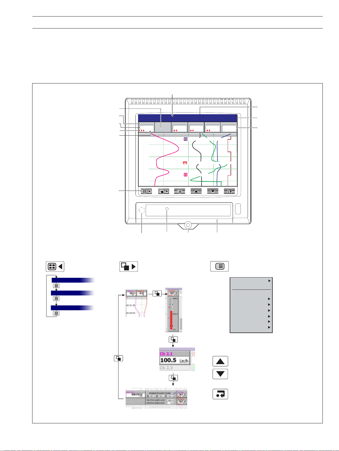
2.2 Displays and Controls – Figs. 2.1 and 2.2
In normal day-to-day use, the instrument is operated via the Operator Keys located along the bottom of the screen.
Process Group Name
Group Key
Selects a different
process group.
Process Group 1
Process Group 2
Instrument Status & Logs
Channel not enabled
Short Channel Tag
Current Value
Alarm Status
Engineering Units
Operator Keys
Process Group 1
Level
010
12:00:00
11:59:15
11:58:30
11:57:45
Programming
Socket
(Inside Door)
View Key
Selects a different process view
or log.
Chart View –
see Section 2.3
Digital Indicator
View – see
Section 2.5
2.08
metres
In Flow
204.9
l/hr
Door Lock
Bargraph Views –
see Section 2.4
Jacking
Screw and
Fitting for
Tamper-proof
Temp
Out Flow
198.9
l/hr
12:00:30 High Out Flow Rate
11:58:53 Duty/Standby Switched
11:58:00 High Level
Seal
195
Media
Door
Status Icons –
see inside rear fold-out
28/03/00
14:52:00
Alarm 1
On
°C
Menu Key
Displays or hides the context-sensitive operator
menu associated with each view:
Current
Date and Time
Digital ON or OFF tag,
according to input status
Configuration
Setup
Historical Review
Operator Messages
Chart Annotation
Screen Interval
Scales
Trace Select
Alarm Acknowledge
Also cancels the menu without making a
change or returns to the previous menu level.
Up/Down Keys
Highlights menu items and scrolls through
previously recorded data.
Process View – see Section 2.6
Fig. 2.1 Displays and Controls
Enter Key
Selects the highlighted menu item.
3
Page 6
…2 OPERATION
…2.2 Displays and Controls
Process Group 1
(Recording Channels 1.1 to 1.6)
Chart View
Pressure
Level
2.08
metres
010
12:00:00
11:59:00
11:58:00
11:57:00
Vertical Bargraph
Pressure
Level
2.08
metres
5.0
2.5
0.0
Horizontal Bargraph
0.0
0.0
0
0
0
Out Flow
In Flow
198.9
204.9
4
l/hr
bar
High Level
Out Flow
In Flow
198.9
204.9
4
l/hr
bar
5.0
300
2.5
150
0.0
0
2.5
2.5
150
150
125
l/hr
High Out Flow Rate
l/hr
300
150
0.0
28/03/00
14:52:00
Alarm 1
Temp
On
195
°C
28/03/00
14:52:00
Alarm 1
Temp
On
195
°C
250
125
0
28/03/00
14:52:00
Level
2.08
5.0
metres
Pressure
4
5.0
bar
In Flow
204.9
300
l/hr
Out Flow
198.9
300
l/hr
Temp
195
250
°C
Alarm 1
On
Process Group 2
(Recording Channels 2.1 to 2.6)
Process Group 1
12:00:30 High Out Flow Rate
11:59:15
5.0
2.5
0.0
12:00:00
11:58:30
11:57:45
In Flow
204.9
4
l/hr
bar
300
150
0
2.5
2.5
150
150
125
12:00:00
010
Vertical Bargraph
Pressure
Level
2.08
metres
5.0
2.5
0.0
Horizontal Bargraph
0.0
0.0
0
0
0
11:58:00 High Level
11:58:53 Duty ON, Standby OFF
11:57:00
Out Flow
198.9
l/hr
300
150
0.0
28/03/00
12:00:45
Level
2.08
metres
Pressure
In Flow
204.9
l/hr
Out Flow
198.9
Alarm 1
On
11:56:15
11:57:45
28/03/00
14:52:00
Alarm 1
Temp
On
195
°C
250
125
0
28/03/00
14:52:00
Level
2.08
5.0
metres
Pressure
5.0
In Flow
204.9
300
Out Flow
198.9
300
Temp
195
250
Alarm 1
On
25°C / 77°F
25°C / 77°F
28/03/00
14:52:00
28/03/00
14:52:00
Instrument Status
VERSION
Software
4
bar
l/hr
4
bar
l/hr
l/hr
°C
SM 2001/1
System
1.0.130
ARCHIVING
Group 1 Filename
Group 2 Filename
% Memory used
Time left
Totalizer Log
No Tag/Value Source Tag Date Time
Total Daily In Flow In Flow 28/03/00 14:52
0005402801 Litres
225.4 l/hr
110.9 l/hr
201.0 l/hr
Total Daily Out Flow Out Flow 28/03/00 14:52
0005402060 Litres
229.1 l/hr
100.1 l/hr
200.9 l/hr
CJ TEMPERATURES
A
B
Process Group 1
Process Group 2
80.5%
5 days
Digital Indicator
Level
Level
In Flow
204.4
Temp
Process View
Total Daily In Flow
0005402801
Total Daily Out Flow
0005402060
2.08
578494
0005402801
195
Tank 1 Low Level
Tank 1 High Level
Tank 1 Low Pressure
Tank 1 High Pressure
litres
litres
Tank 1 Low Temp
Tank 1 High Temp
Pressure
Out Flow
Alarm 1
Storage Tank 1 In Flow
225.4 110.9 201.0
Storage Tank 1 Out Flow
229.1 100.1 200.9
198.4
On
1.25
4.75
0.25
4.75
150
250
28/03/00
14:52:00
578494
0005402060
28/03/00
14:52:00
Level
Pressure
In Flow
204.9
Out Flow
198.9
Temp
Alarm 1
2.08
On
Audit Log
No Alarm Event Tag Date Time
00 Power Restored 25/03/00 11:59
01 I/O Configuration 25/03/00 12:01
02 Common Configuration 25/03/00 12:05
03 Group 1 Configuration 25/03/00 12:09
04 Ch1.1 to 6 Config 25/03/00 12:10
05 AIN Cal, Module A 25/03/00 12:15
06 System Alarm
Note. Only process
groups and views that have
been enabled are displayed –
see Section 4.5, Process
Group Configuration.
2.08
578494
198.4
0005402060
On
1.25
4.75
0.25
4.75
150
250
28/03/00
14:52:00
4
28/03/00
14:52:00
Level
Pressure
In Flow
204.9
Out Flow
198.9
Temp
Alarm 1
2.08
On
metres
3
m
metres
4
bar
l/hr
l/hr
195
°C
Digtial Indicator
metres
m
Pressure
3
Out Flow
Alarm 1
Level
Level
2.08
4
2.08
578494
In Flow
204.4
0005402801
Temp
195
metres
4
bar
l/hr
l/hr
195
°C
Process View
Total Daily In Flow
0005402801
Total Daily Out Flow
0005402060
litres
litres
Tank 1 Low Level
Tank 1 High Level
Tank 1 Low Pressure
Tank 1 High Pressure
Tank 1 Low Temp
Tank 1 High Temp
Storage Tank 1 In Flow
225.4 110.9 201.0
Storage Tank 1 Out Flow
229.1 100.1 200.9
28/03/00
14:52:00
Fig. 2.2 Overview of Operator Displays
4
Page 7
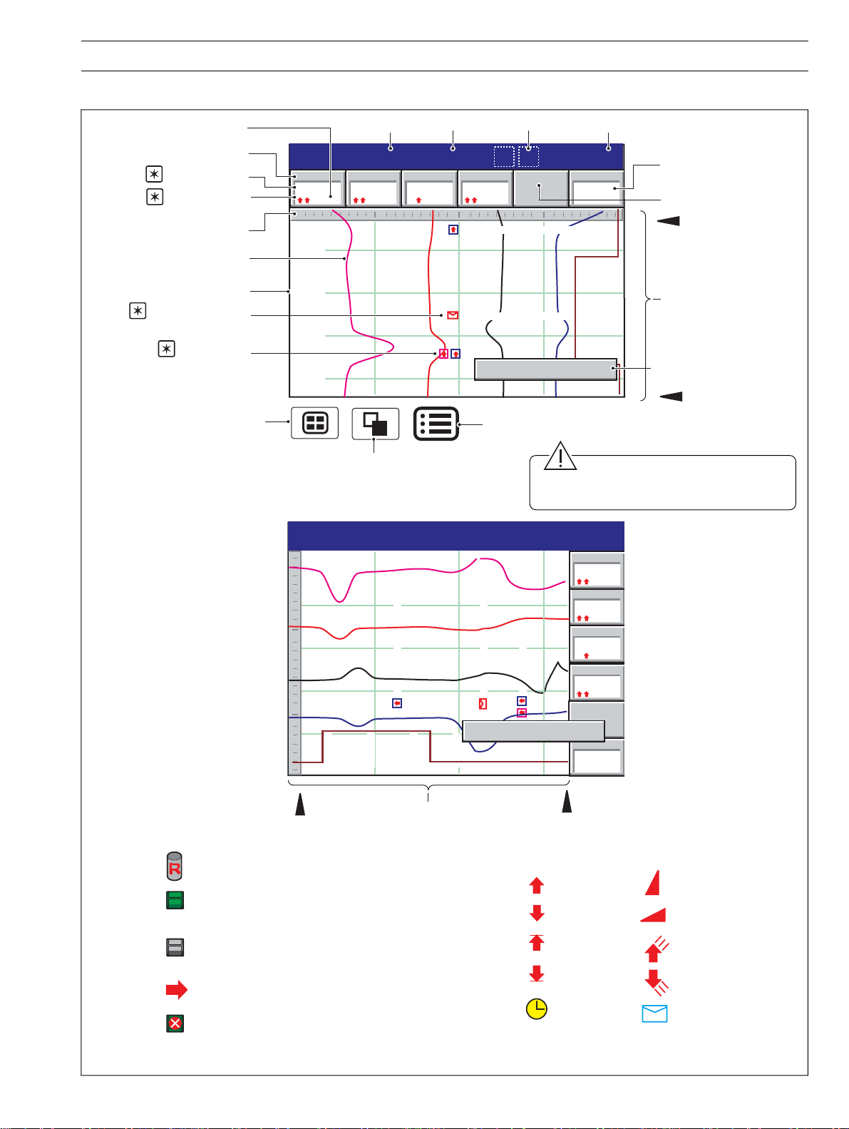
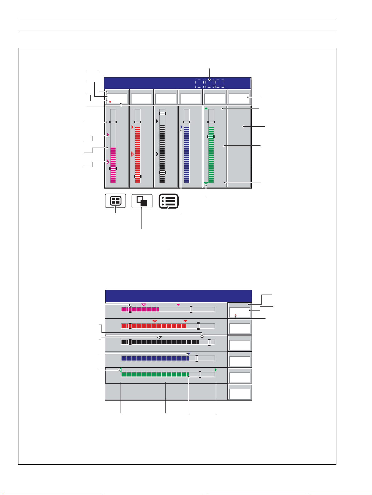
2.3 Chart Views (Horizontal and Vertical) – Fig. 2.3
2 OPERATION…
Units
Short Channel Tag
1
Current Value
2
Alarm Status
Scale Bar
Chart Trace
Time Stamp
3
Operator Message
Annotation
3
Alarm Event
Annotation
Selects next Process Group
(if enabled) or Status View
In Flow
204.9
Title Bar
Out Flow
198.9
l/hr
l/hr
12:00:30 High Out Flow Rate
11:58:53 Duty ON, Standby OFF
11:58:00 High Level
Duty/Standby Change
Status Icons
28/03/00
Current Date and Time
12:00:45
Alarm 1
On
Digital On/Off Tag
Channel Not Used
Newest Data
Screen Interval
Operator Message
(appears for 1 second)
Group Tag
Process Group 1
metres
Pressure
4
bar
Level
2.08
010
12:00:00
11:59:15
11:58:30
11:57:45
Oldest Data
Opens the Operator Menu for
the current view
Selects the next enabled
view in the group
(Bar, Digital or Process)
Caution. Do not remove media
while the external media update icon is
displayed.
Process Group 1
12:00:30 High Out Flow Rate
11:58:53 Duty ON, Standby OFF
28/03/00
12:00:45
Level
Pressure
In Flow
204.9
Out Flow
11:58:00 High Level
198.9
2.08
metres
4
bar
l/hr
l/hr
010
Newest Data
Status Icons
Historical Review active – see overleaf
External archive media on-line
(green icon – shaded area indicates % used)
External archive media off-line
(grey icon – shaded area indicates % used)
External archive media update in progress.
Media 100% full, archiving stopped (white
cross on red background)
12:00:00
11:59:15
11:58:30
Screen Interval
Fig. 2.3 Chart View
Duty/Standby Change
12:00:00
11:57:00
11:57:45
Alarm Event Icons
Digital Indicators and Chart View
Alarm 1
11:56:15
Oldest Data
High Process
Low Process
High Latch
Low Latch
Real time
On
Fast Rate
Slow Rate
High Annunciate
Low Annunicate
Operator Message
5
Page 8
…2 OPERATION
…2.3 Chart View
Notes.
1. Current Values
The Current Value, shown on the digital indicators at the top of the screen, is the latest instantaneous value and its update
rate is not affected by the recording sample rate.
If the current value in the digital indicator is displayed in red, recording has been stopped for that channel – see Section 4.5.1,
Setting the Recording Parameters.
Traces are shown only when that particular channel is being recorded. When channels are set to stop, the trace continues
to be shown for up to one sample period.
2. Alarm Status
•Flashing Red – Alarm Active and Unacknowledged
•Continuous Red – Alarm Active and Acknowledged
3. Alarm Event and Operator Message Annotations
Alarm Event and Operator Message annotations are not shown on the chart unless enabled –
see 'Chart Annotation' on Page 8 and Section 4.5.2.
If Alarm event annotation is enabled and an alarm becomes active, a red alarm icon surrounded by a channel-colored box is
displayed at the point at which the alarm occured, together with the alarm time and tag.
11:58:00 1.1A High Level
If more than one alarm occurs in the same sample period:
• If the second alarm on a channel becomes active its icon is added behind the first.
• If more than one operator messages is active (max. six) a second icon is added behind the first.
• New alarm icons appear to the left of earlier icons.
• The time and tag of the oldest alarm (right-most icon) only is displayed.
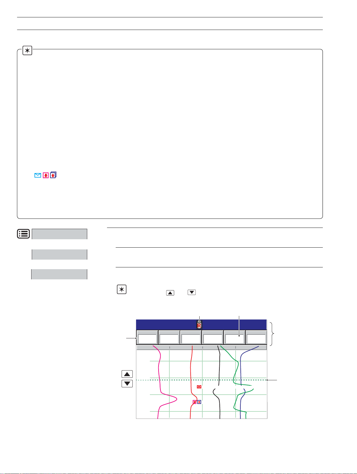
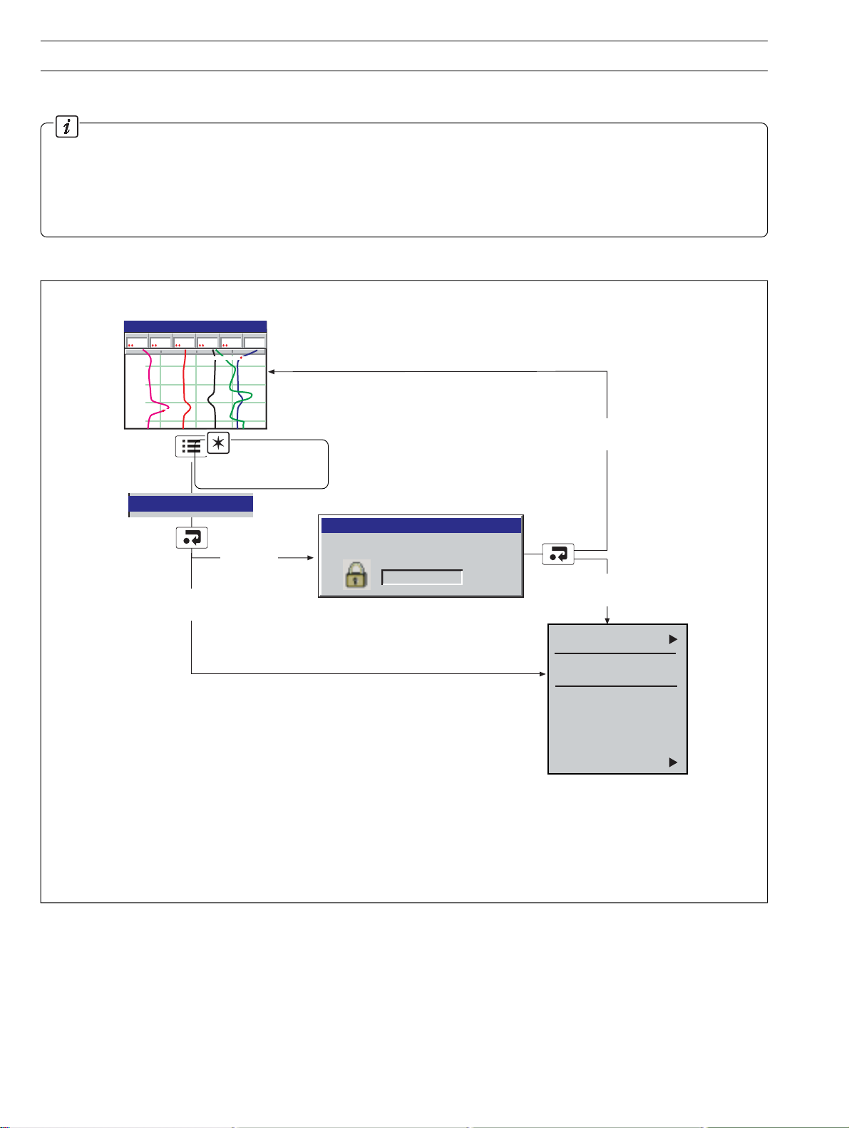
Configuration
Setup
Historical Review
Select the Configuration Level – see Section 4.
Select the Setup Level – see Section 3.
Select Historical Review to view previously recorded data stored in the instrument's
onboard memory.
Note. Use the and keys to move backwards and forwards through the
recorded data.
Digital
Indicators
Historical
Review Active
Process Group 1
In Flow
204.9
4
bar
2.08
metres
Pressure
Level
010
12:00:00
11:59:00
11:58:00
11:57:00
Out Flow
198.9
l/hr
11:58:23 Duty/Standby Pumps Switched
11:57:30 High Level
Invalid data – e.g.
recording disabled
Temp
- - - -
l/hr
°C
28/03/00
11:59:30
Alarm 1
On
Values displayed
indicate the process
status at the cursor
position
Cursor
6
Page 9
…2.3 Chart View
2 OPERATION…
Notes.
While in Historical Review mode:
• Recording of new data continues unless stopped from the Setup Menu – see
Section 3.3.
• Invalid historical data (e.g. when recording has stopped) is denoted by '– – – –' in the
digital indicator.
• Where the trace at the cursor position represents more than one sample, the indicators
flash between the maximum and minimum values of those samples.
• Menu options remain active, allowing the screen interval to be changed, different
scales and channels to be selected, etc.
• Operator messages are added to the alarm event log at the present time, not historical
time.
• All data stored in the instrument's internal memory can be viewed.
• The display can be scrolled back to the start of the oldest data.
•Archiving to removeable media does not occur but all data recorded in the internal
memory buffer during this time is archived on exiting Historical Review mode.
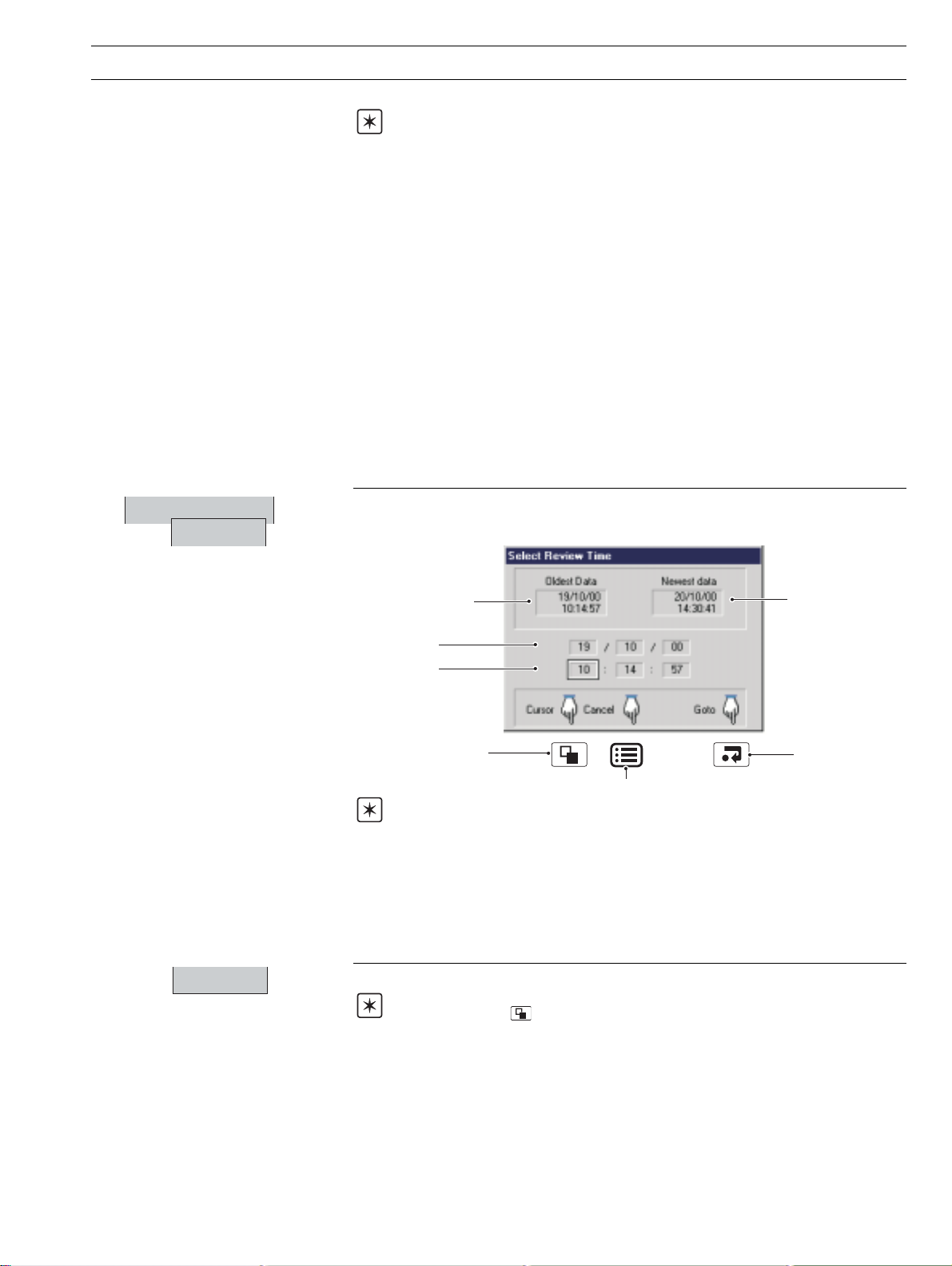
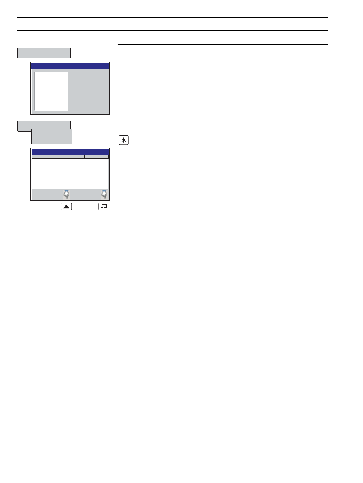
✔ Historical Review
Goto
Select Goto to move to data stored in the instrument's onboard memory that was
recorded at a specific date and time.
Oldest data in
internal memory
Ta rget date
Ta rg et time
Moves cursor between
target day, month, year,
hours, minutes & seconds
Returns to Menu
Newest data in
internal memory
Goes to the chart
view display, at the
selected date and
time.
Notes.
• Once internal memory becomes full, oldest data is overwritten by newest data. If
historical review has been selected for some time, the oldest data present may no longer
be available.
• The instrument exits historical review mode automatically after 3 hours or when the
oldest channel data file start time (which changes as files wrap) is earlier than the time
that historical review mode was selected.
Exit
Select Exit to return to the real-time recording display.
Note. Pressing the key also exits Historical Review mode and displays the next
enabled view.
7
Page 10
…2 OPERATION
…2.3 Chart View
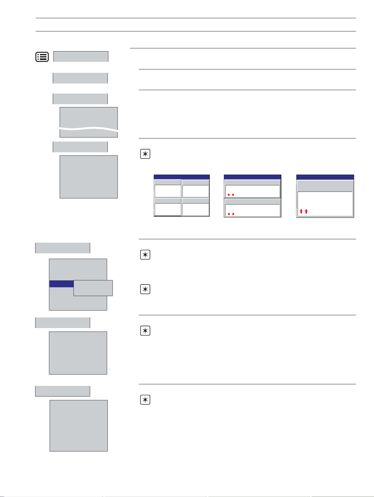
Operator Messages
Message 1
Duty/Stby Switched
Message 3
Message 6
Chart Annotation
✓ Alarms
✓ Operator Messages
Screen Interval
18 Seconds/Screen
90 Seconds/Screen
1 Minute/Screen
✔3 Minutes/Screen
7 Days/Screen
Add one of six preset Operator Messages to the alarm event log. The selected message
is displayed briefly in a dialog box. If Operator Message annotation is selected (see Chart
Annotation below) the message is also added to the chart.
Note. When the instrument is in Historical Review mode, Operator Messages
generated are added at the current time, not the time indicated by the cursor.
If an alarm or operator message is obscuring part of a chart trace, use the Chart
Annotation option to hide or display alarms and messages on the screen.
Select the annotation required. ✓ indicates the annotations selected.
The possible combinations are: No annotation (Alarms and Operator Messages both
disabled); Alarm annotation only or Alarms and Operator Message annotation. Operator
Message Annotation cannot be enabled unless Alarm Annotation is also enabled.
Notes.
• If more than 15 icons are present on the screen, chart annotation is disabled
automatically.
• When chart annotation is disabled, new operator messages and alarms are still added
to the Alarm event log – see Section 2.7
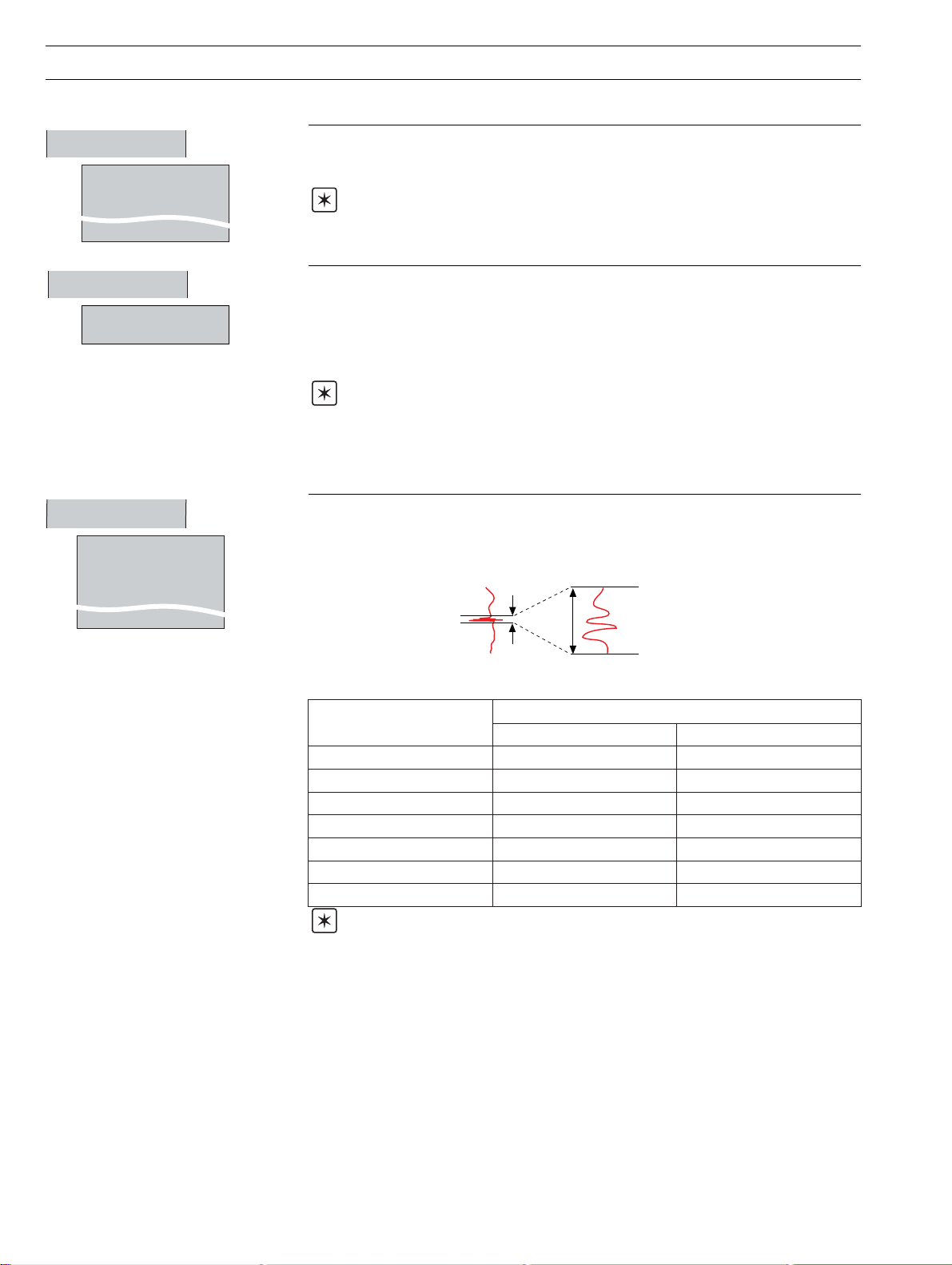
Use the Screen Interval to change the amount of data displayed on the screen. A longer
screen interval displays more data, a shorter screen interval displays data over a shorter
time period, but in more detail. In both cases, the full trace is preserved by plotting the
maxiumum and minimum samples for each display point.
Longer interval =
better overview
Shorter interval
= more detail
The maximum screen interval is determined by the sample rate.
gnitteSetaRelpmaS
s1<neercs/setunim9otpUneercs/setunim31otpU
s01dna1neewteBneercs/ruoh1otpUneercs/sruoh5.1otpU
s02nahtssel,s01nahteroMneercs/sruoh21otpUneercs/sruoh81otpU
s04dna02neewteBneercs/yad1otpUneercs/syad5.1otpU
s06dna04neewteBneercs/yad2otpUneercs/syad3otpU
s041nahtssel,s06nahteroMneercs/syad3otpUneercs/syad5.4otpU
s041nahteroMneercs/syad7otpUneercs/syad01otpU
weiVtrahClacitreVweiVtrahClatnoziroH
lavretnIneercSxaM
Notes.
•A 'Please Wait' dialog box appears while the instrument retrieves data from storage.
• Selecting a different screen interval does not affect the rate at which data is sampled.
• When in historical review mode, changing the scan interval may cause the time at the
cursor position to change slightly.
8
Page 11

…2.3 Chart View
2 OPERATION…
Scales
Select
✔ Ch 1.1 Level
Ch 1.2 Pressure
Auto Scroll
Trace Select
✔ Ch 1.1 Level
✔ Ch 1.2 Pressure
✔ Ch 1.3 In Flow
✔ Ch 1.4 Out Flow
Ch 1.5 Temp
✔ Ch 1.6 Alarm 1
Show all
Alarm Acknowledge
Ch 1.1 Level
Ch 1.2 Pressure
Ch 1.3 In Flow
Ch 1.4 Out Flow
Ch 1.5 Temp
Ch 1.6 Alarm 1
All
Scales
Select
Select the scale displayed in the scale bar at the top of the chart window. For digital
channels, the On and Off tags are displayed at the corresponding position on the scale bar.
Select Auto Scroll to display the scale for each channel in turn for a few seconds.
Note. If Auto Scroll is selected, only enabled and selected channels' scales are
displayed.
Hide individual channel traces to improve chart clarity.
Traces are identified by the Channel Number (e.g. Ch1.1) and its short tag. In this example,
the trace for Channel 5 is not shown.
Note. The recording of a channel's data is not affected by this operation and the
instantaneous channel values are still shown on the indicators at the top of the screen.
Used to acknowledge active alarms in the current process group either individually or
globally.
Note. Active alarms are identified by a flashing red 'Alarm Status' icon in the bottom
left hand corner of the associated channel indicator – see Fig. 2.4.
If neither alarm on a particular channel is configured, the short channel tag is shown
greyed-out in the menu.
9
Page 12
…2 OPERATION
2.4 Bargraph Views (Horizontal and Vertical)
Short Channel Tag
Current Value
Alarm Status –
see Rear fold-out
Engineering Units
Alarm Trip Level
(not shown for slow and
fast rate alarms)
Maximum Value
(solid color)
Instantaneous Value
Minimum Value
(white fill)
Process Group 1
metres
5.0
2.5
Pressure
5.0
2.5
Level
2.08
Status Icons –
see Rear Foldout
28/03/00
14:52:00
195
250
125
Alarm 1
On
°C
Digital On or Off tag,
according to input status
Engineering Range High Value
Digital
Channel
Engineering Range
Middle Value
Temp
l/hr
300
150
300
150
Out Flow
198.9
l/hr
In Flow
204.9
4
bar
0.0
Selects the next Process Group
(if enabled) or Status View
Selects the next enabled view in the group
(Digital Indicator, Process or Chart)
Opens the Operator Menu for
Alarm Trip Level
Process Group 1
(not shown for slow and
fast rate alarms)
Maximum Value
(solid color)
Minimum Value
(white fill)
Identical Maximum
and Minimum Values
Minimum below
engineering limit,
Maximum above
engineering limit
0.0
0.0
0
0
0
0.0
0
0.0
Identical Maximum and Minimum Values
the current view
A – Vertical Bargraph View
2.5
2.5
150
150
125
0
Minimum below engineering
limit, maximum above
engineering limit
28/03/00
14:52:00
Level
5.0
5.0
300
300
250
2.08
metres
Pressure
In Flow
204.9
Out Flow
198.9
Temp
195
Alarm 1
4
bar
l/hr
l/hr
°C
On
Engineering Range Low Value
Short Channel Tag
Current Value
Alarm Status – see
Rear Fold-out
10
Engineering
Range
Low Value
Engineering
Range
Middle Value
Instantaneous
Value
Engineering
Range High
Value
B – Horizontal Bargraph View
Fig. 2.4 Bargraph Views
Page 13

…2.4 Bargraph Views (Horizontal and Vertical)
2 OPERATION…
Configuration
Setup
Operator Messages
Message 1
Duty/Stby Switched
Message 3
Message 6
Max/Min Reset
Ch 1.1 Level
Ch 1.2 Pressure
Ch 1.3 In Flow
Ch 1.4 Out Flow
Ch 1.5 Temp
Ch 1.6 Alarm 1
All
Alarm Acknowledge
Ch 1.1 Level
Ch 1.2 Pressure
Ch 1.3 In Flow
Ch 1.4 Out Flow
Ch 1.5 Temp
Ch 1.6 Alarm 1
All
Select the Configuration level – See Section 4.
Select the Setup level – see Section 3.
Add one of six preset messages to the alarm event log. The selected operator message is
displayed on-screen briefly.
Reset the Maximum and Minimum value markers on one or all channels to the current
value.
Note. These Maximum and Minimum values are for display purposes only. They are
not saved or archived and are not connected to the Totalizer Maximum and Minimum
Values displayed in the Process View.
Note. These Maximum and Minimum values are reset whenever the current
configuration has been changed or is re-saved.
Acknowledge active alarms in the current process group either individually or globally.
Note. Active alarms are identified by a flashing red 'Alarm Status' icon in the bottom
left hand corner of the associated channel indicator – see Fig. 2.4.
If neither alarm on a particular channel is configured, the short channel tag appears
greyed-out in the menu.
11
Page 14
…2 OPERATION
2.5 Digital Indicator View – Fig. 2.5
Status Icons
4
578494
28/03/00
14:52:00
metres
bar
3
m
litre/h
3
m
Short Channel Tag
Current Value
Alarm Status –
see Rear Fold-out
Engineering Units
Selects the next Process Group
(if enabled) or the Status View
Notes.
• Indicators resize automatically according to the number of channels displayed.
•Totalizer option must be fitted and Totalizers must be configured and enabled before they can be
displayed – see Section 4.6.5.
•Totalizer values are shown in red if the totalizer is not running.
Process Group 1
Level
Level
2.08
2.08
578494
In Flow
204.4
0005402801
Temp
195
Selects the next enabled
view in the group
(Process, Chart or Bargraph)
Pressure
metres
metres
3
m
2.08
Out Flow
litre/h
m
3
198.4
0005402060
Alarm 1
°C
Opens the Operator Menu for
the current view
On
Channel Units
To talizer Units
To ta lizer Value
12
Fig. 2.5 Digital Indicator View
Page 15
…2.5 Digital Indicator View
2 OPERATION…
Configuration
Setup
Operator message
Message 1
Duty/Stby Switched
Message 3
Message 6
Channel select
✔ Ch 1.1 Level
✔ Ch 1.2 Pressure
✔ Ch 1.3 In Flow
✔ Ch 1.4 Out Flow
✔ Ch 1.5 Temp
✔ Ch 1.6 Alarm 1
Select the Configuration level – see Section 4.
Select the Setup level – see Section 3.
Add one of six preset operator messages to the alarm event log. The selected message is
displayed on screen briefly.
Hide or display individual channel indicators.
Note. The display is re-adjusted according to the number of channels selected. This
has no effect on the recording of the channel.
Process Group 1
Level
26.78
Out Flow
198.4
0005402060
metres
m
gal/hr
3
In Flow
204.4
Temp
28/03/00
14:52:00
0005402801
m
195
°C
Process Group 1
In Flow
gal/hr
3
204.4
Out Flow
0005402801
198.4
m
m
28/03/00
gal/hr
3
gal/hr
3
14:52:00
Process Group 1
In Flow
204.4
0005402801
28/03/00
14:52:00
gal/hr
3
m
One Channel SelectedTwo Channels SelectedThree or Four
Channels Selected
Totalizer stop/go
Ch 1.1 Level
Ch 1.2 Pressure
Ch 1.3 In Flow
Ch 1.4 Out Flow
✔ Stop
Ch 1.5 Temp
Ch 1.6 Alarm 1
All
Totalizer reset
Ch 1.1 Level
Ch 1.2 Pressure
Ch 1.3 In Flow
Ch 1.4 Out Flow
Ch 1.5 Temp
Ch 1.6 Alarm 1
Alarm acknowledge
Ch 1.1 Level
Ch 1.2 Pressure
Ch 1.3 In Flow
Ch 1.4 Out Flow
Ch 1.5 Temp
Ch 1.6 Alarm 1
All
Go
Stop and start individual totalizers.
Note. Displayed only if Totalizer option fitted.
Channel totalizers that have not been enabled in the configuration level are shown greyed
out.
Note. When a totalizer is not running (i.e. Stop is selected), the corresponding
totalizer value is shown in red.
Reset the totalizer value to the totalizer preset value.
Notes.
• Displayed only if Totalizer option fitted.
• Channel totalizers that have not been enabled in the Configuration level are shown
greyed out
Acknowledge active alarms individually, in the current process group or globally.
Note. Active alarms are identified by a flashing red 'Alarm Status' icon in the bottom
left hand corner of the associated channel indicator.
If neither alarm on a particular channel is configured, the short channel tag is greyed-out in
the menu.
13
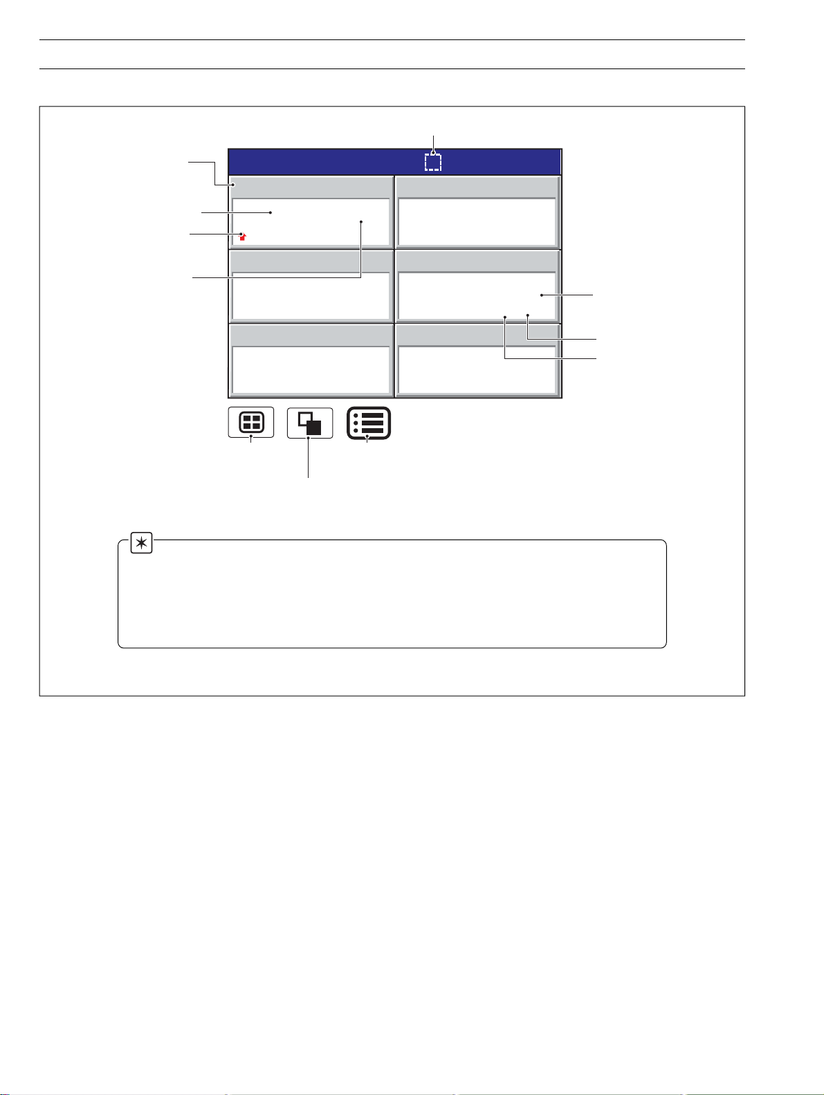
Page 16
…2 OPERATION
2.6 Process View – Fig. 2.6
Note. This view is available only if the Totalizer option is fitted.
To ta lizer not
enabled in
configuration level
To ta lizer
Tag Name
To ta lizer
Value
Selects the next Process Group
(if enabled) or the Status View
Selects the next enabled view
(Bargraph, Digital Indicator or Chart)
Opens the Operator Menu for
Alarm Tag
Process Group 1
Total Daily In Flow
0005402801
Total Daily Out Flow
0005402060
the current view
Tank 1 Low Level
Tank 1 High Level
Tank 1 Low Pressure
Tank 1 High Pressure
Low In Flow Rate
High In Flow Rate
litres
High Out Flow Rate
litres
Tank 1 Low Temp
Tank 1 High Temp
Alarm Trip Level
1.25
4.75
0.25
4.75
280
250
150
200
40
Alarm Acknowledged
28/03/00
14:52:00
Level
2.08
metres
Pressure
4
bar
In Flow
204.9
l/hr
Out Flow
198.9
l/hr
Temp
195
°C
Alarm 1
On
Short Channel Tag
Instantaneous Value
Alarm Status
A – Process View (Alarms)
Channel Source Long Tag
Total Daily In Flow
0005402801
litres
Storage Tank 1 In Flow
225.4 110.9 201.0
Max
Min
Average
In Flow
204.9
l/hr
Values since last totalizer reset or totalizer wrap. Calculated only while
the totalizer is enabled. Updated only while the totalizer is running.
B – Process View (Statistics)
Notes.
• Only totalizers that have been enabled in the configuration level are displayed.
• When a totalizer is not running (i.e. Stop is selected), the corresponding totalizer value is shown
in red.
Fig. 2.6 Process View
14
Page 17

…2.6 Process View
2 OPERATION…
Configuration
Setup
View Select
✔ Alarms
Statistics
Operator Messages
Message 1
Duty/Stby Switched
Message 3
Message 6
Totalizer Stop/Go
Ch 1.1 Level
Ch 1.2 Pressure
Ch 1.3 In Flow
Ch 1.4 Out Flow
✔ Stop
Ch 1.5 Temp
Ch 1.6 Alarm 1
All
Go
Select the Configuration level – see Section 4.
Select the Setup level – see Section 3.
Switch between the Alarm View and Statistics View.
Note. If a channel's totalizer has not been enabled in the Configuration level, Alarm
trip levels are shown in place of the channels statistics. If no alarms are enabled, the
channel long tag is displayed for that channel.
Add one of six preset messages to the alarm event log. The selected message is displayed
on screen briefly. Messages are set in the Configuration level – see Section 4.
Stop and start individual totalizers.
Note. Channel totalizers that have not been enabled in the Configuration level are
shown greyed out.
Note. When a totalizer is not running (i.e. Stop is selected), the corresponding
totalizer value is shown in red.
Totalizer Reset
Ch 1.1 Level
Ch 1.2 Pressure
Ch 1.3 In Flow
Ch 1.4 Out Flow
Ch 1.5 Temp
Ch 1.6 Alarm 1
Alarm Acknowledge
Ch 1.1 Level
Ch 1.2 Pressure
Ch 1.3 In Flow
Ch 1.4 Out Flow
Ch 1.5 Temp
Ch 1.6 Alarm 1
All
Reset the totalizer value to the totalizer preset value.
Note. Channel totalizers that have not been enabled in the Configuration level are
shown greyed out.
Acknowledge active alarms in the current process group, either individually or globally.
Note. Active alarms are identified by a flashing red 'Alarm Status' icon in the bottom
left hand corner of the associated channel indicator – see Fig. 2.6.
If neither alarm on a particular channel is configured, the channel short tag is greyed out in
the menu.
15
Page 18
…2 OPERATION
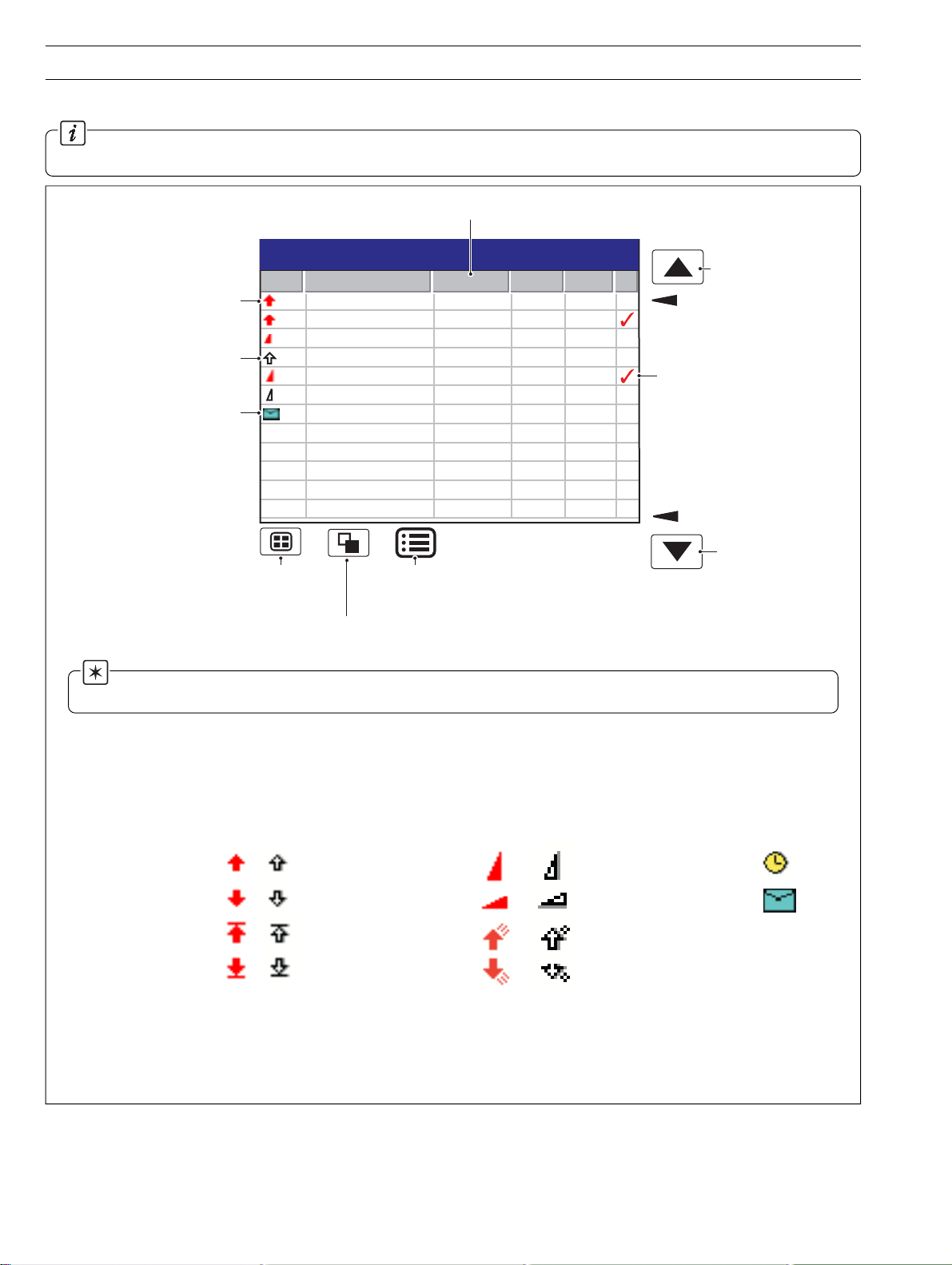
2.7 Alarm Event Log – Fig. 2.7
Information. This view provides an historical log of all alarm events in the sequence in which they occurred. To view the
current status of all alarms, choose the Process View – see Section 2.6.
Short tag of the alarm's source
28/03/00
14:52:00
View previous
page of data
Oldest Data
Alarm Acknowledged
Newest Data
View next
page of data
Alarm becomes active
(Active transition)
Alarm becomes inactive
(Inactive transition)
Operator Message
Alarm Event Log
No Alarm Event Tag Source Tag Date Time
00 Tank 1 High Level Level 28/08/00 14:01:22
01 Tank 1 High Level Level 28/08/00 14:03:51
02 High Out Flow Rate Out Flow 28/08/00 14:09:09
03 Tank 1 High Level Level 28/08/00 14:11:33
04 High Out Flow Rate Out Flow 28/08/00 14:12:47
05 High Out Flow Rate Out Flow 28/08/00 14:15:01
06 Duty/Standby Change Out Flow 28/08/00 14:31:19
Selects
Process
Group 1
Selects the
Totalizer Log
Opens the
Operator Menu for
the current view
Note. When the alarm event log has reached the maximum number of entries, the oldest data is overwritten by the
newest. Entries are renumbered so that the number of the oldest entry is always 00.
High Process Alarm
Low Process Alarm
High Latch Alarm
Low Latch Alarm
Active
Inactive
A – Alarm Event View
Active
Fast Rate Alarm
Slow Rate Alarm
High Annunciate Alarm
Low Annunicate Alarm
B – Alarm Event Icons
Fig. 2.7 Alarm Event Log
Inactive
Real time alarm
Operator Message
16
Page 19

…2.7 Alarm Event Log
2 OPERATION…
Configuration
Setup
Filter
Group 1 Alarms
Group 2 Alarms
Operator Messages
Active Transitions Only
Alarm Acknowledge
Group 1 Alarms
Group 2 Alarms
Ch 1.1 Level
Ch 1.2 Pressure
Ch 1.3 In Flow
Ch 1.4 Out Flow
Ch 1.5 Temp
Ch 1.6 Alarm 1
All
Select the Configuration level – see Section 4.
Select the Setup level – see Section 3.
Select the entries displayed in the log. 4 Indicates categories currently displayed.
Note. Hiding and displaying log entries does not affect the recording of events in the
log.
Note. All selected alarm event transitions (from inactive to active, from active to
acknowledged, from acknowledged to inactive, from active to inactive) appear in the
sequence in which they occurred.
Note. Selecting 'Active Transitions Only' displays entries for alarms when made
active and hides all acknowledged & inactive transistions.
Used to acknowledge active alarms in each of the process groups, either individuallly or
globally.
Note. If neither alarm on a particular channel is configured, the short channel tag is
greyed-out in the menu.
17
Page 20
…2 OPERATION
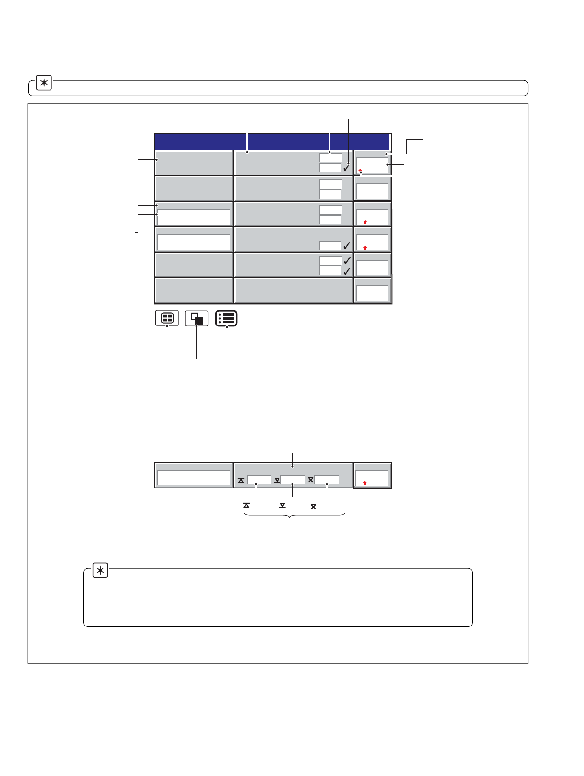
2.8 Totalizer Log – Fig. 2.8
Information.
• This view is displayed only if the Totalizer option is fitted.
• This view provides an historical log of totalizer activity. To view the current totalizer status, choose the Process or Digital View.
• When the totalizer log has reached the maximum number of entries defined in the Configuration level (see Section 4.4.3), the
oldest data is overwritten by the newest.
• The logging of totalizer values can be triggered at pre-determined intervals or by a digital signal assigned to the Totalizer Log
Source – see Section 4.6.5.
View previous
page of data
Icon –
see list below
Log Entry Number
Batch total at the
time of the event
Max., min. and
average of the value
being totalized at the
time of the event
Note. Maximum, Minimum and Average statistics are not shown unless
enabled in the Filters menu – see overleaf.
Totalizer Log
No Tag/Value Source Tag Date Time
00 Total Daily In Flow In Flow 28/03/00 14:52
0005402801 Litres
225.4 l/hr
110.9 l/hr
201.0 l/hr
01 Total Daily Out Flow Out Flow 28/03/00 14:52
0005403191 Litres
235.8 l/hr
110.9 l/hr
210.0 l/hr
02 Total Daily Out Flow Out Flow 28/03/00 15:01
0005403120 Litres
Selects
Process
Group 1
Selects the
Audit Log
Opens the
Operator Menu for
the current view
28/03/00
14:52:00
Oldest
Data
Newest
Data
View next page
of data
18
Totalizer Started
Totalizer Stopped
Totalizer Wrapped
Totalizer Reset
Intermediate Value Reached
Timed Event
Triggered Event
Power Failed
Power Restored
Fig. 2.8 Totalizer Log
Batch Total
Maximum input
Minimum input
Average input
Page 21

…2.8 Totalizer Log
2 OPERATION…
Configuration
Setup
Filter
Group 1 Totalizers
Group 2 Totalizers
Statistics
Select the Configuration level – see Section 4.
Select the Setup level – see Section 3.
Select the log entries that are displayed. This does not affect which events are recorded in
the log.
Note. ✔ indicates entries displayed.
'Statistics' displays the maximum, minimum and average values of the analog value being
totalized.
These values are reset when the totalizer is reset and are updated only when the totalizer
is running.
19
Page 22
…2 OPERATION
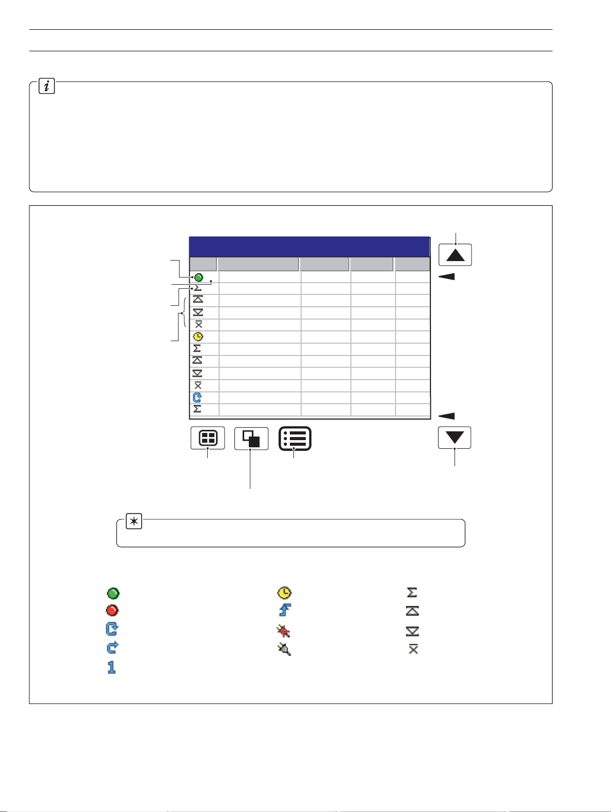
2.9 Audit Log – Fig. 2.9
Information.
• This view provides an historical log of system activity.
• When the audit log has reached the maximum number of entries, the oldest data is overwritten by the newest.
View previous
page of data
Audit Log
No Alarm Event Tag Date Time
00 Power Restored 25/03/00 11:59
01 Configuration Change, Oper 1 25/03/00 12:01
02 Input Calibration 25/03/00 12:15
03 System Alarm 25/03/00 13:17
28/03/00
14:52:00
Oldest Data
Media Inserted
Media Removed
System Error
Time/date Changed
Configuration
Selects
Process
Group 1
Opens the
Operator Menu for
Selects the
Status View
the current log
File Deleted
Power Failed
Power Restored
Calibration Change
Fig. 2.9 Audit Log
Select the Configuration level – see Section 4.
Newest Data
View next
page of data
Configuration Change
File Created
FTP Logon
20
Setup
Select the Setup level – see Section 3.
Page 23
2.10 Status View – Fig. 2.10
Information.
• This view provides an overview of the instrument's status.
2 OPERATION
Instrument Software Version
Operating System Version
Amount of memory used
on the archive media
currently installed
Approximate time left
before the current archive
media is full, assuming the
amount of data recorded
remains the same
Selects Process Group 1
Selects the Alarm Event Log
Instrument Status
VERSION
Software
System
ARCHIVING
Group 1 Filename
Group 2 Filename
% Memory used
Time left
Opens the Operator Menu for
the current view
SM 2001/01
1001/1
CJ TEMPERATURES
25°C / 77°F
A
25°C / 77°F
B
Process Group 1
Process Group 2
80.5%
5 days
Time Left Display Format
>=1 Day: Days, e.g. '5 Days'
>=1 Hour, <1 Day: Hours, e.g. '10 hours'
<1 Hour: Minutes, e.g. '25 minutes'
Fig. 2.10 Status View
28/03/00
14:52:00
Cold junction temperatures
for Modules A & B; measured
by the built-in cold junction
circuitry.
'Not Used' is displayed if none
of the inputs on the module
are thermocouples.
Configuration
Setup
Select the Configuration level – see Section 4.
Select the Setup level – see Section 3.
21
Page 24
3 SETUP
3.1 Introduction
Information.
Users with Setup access can:
• Start/Stop recording.
• Switch between primary and secondary recording rates.
• Set archiving 'on-line' and 'off-line'.
•View internal and external archive media file directories and delete files
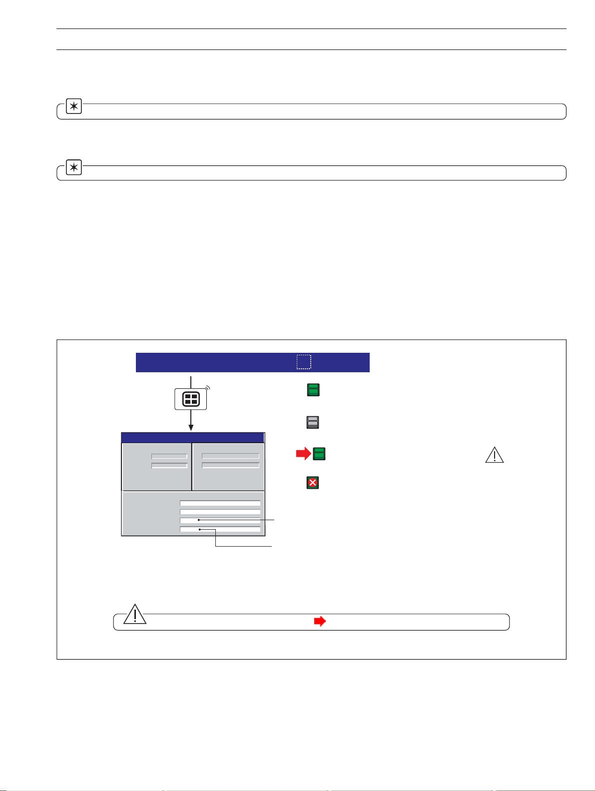
3.2 Accessing the Setup Level – Fig. 3.1
l/hr
High Out Flow Rate
28/03/00
Alarm 1
Temp
On
195
°C
Process Group 1
Pressure
Level
2.08
metres
010
12:00:00
11:59:00
11:58:00
11:57:00
bar
4
High Level
In Flow
204.9
Out Flow
198.9
l/hr
Note. Can be
activated from any
operator screen.
Setup
Setup
Setup
Security
Enabled
Setup Security
Not Enabled
Use the up and down keys to select your password.
Confirm with Enter key
0000
Invalid Setup
Password
Valid Setup
Password
Recording Control
Reset archiving
On-Line
Off-Line
Update
File Viewer
22
Fig. 3.1 Accessing the Setup Level
Page 25

3.3 Setup Menu
3 SETUP…
Recording Control
All
✔ Primary
Reset archiving
Stop
Secondary
Use this menu to stop and start recording or change the sample rate for the channels in the
current Process Group.
The Primary and Secondary sample rates allow a slow rate to be selected for normal
conditions and a faster rate for abnormal alarm conditions in order to record the maximum
amount of detail. The rates are set during configuration – see Section 4.5.1.
Notes.
• Switching between primary & secondary sample rates does not affect the screen
interval on the Chart View.
• When the channels are set to 'Stop' the instantaneous values in the associated
indicator are displayed in red and, after the end of the next sample period, no further
samples are plotted on the associated traces.
• Digital recording channels can only be set to 'Stop' or 'Go'.
• Recording control can also be implemented using digital sources – see Sections 4.5.1
and 4.6.1.
If selected, the date of the oldest unarchived data is set to that of the oldest data in the
internal flash memory. This allows all data in the internal memory to be re-archived to
external media.
Note. Ideally, a blank media storage card should be inserted prior to selecting this
function. If the original archive files are still present on the inserted card after Reset
acrchiving, the new, re-archived files are annotated '_1' to distinguish them from the
original archive files, e.g.
original archive file: 10_00 25Feb02 Zone abc.d00
re-archived file: 10_00 25Feb02 Zone abc_1.d00
On-line
Off-line
To re-archive data:
Insert archive media, with sufficient free space, into the instrument.
Select 'Off-line' in the Setup Menu
Select 'Reset archiving' in the Setup Menu
Select 'On-line' in the Setup Menu
Select amount of data to be archived (if >1 hour of data in internal memory)
Places the archive media on-line, starting the archiving process. Any un-archived data is
stored automatically to the removeable media. If there is un-archived data more than one
day old, a selection box is displayed – see 'Update' overleaf.
Notes.
• When an archive media card/disk is inserted, it is placed automatically on line.
• The On-line function is disabled (greyed out) in the Setup Menu when in Historical
Review mode.
Places the archive media off-line. Recording of channel data into internal memory
continues uninterrupted but archiving to the removeable media is suspended until it is put
on-line again.
Notes.
• Always set the external media Off-line before removing it.
• The Off-line function is disabled (greyed out) in the Setup Menu when in Historical
Review mode.
23
Page 26
…3 SETUP
…3.3 Setup Menu
Update
Select the amount of data to archive
No historical data
< 1 day old
< 2 days old
< 3 days old
< 4 days old
< 5 days old
< 6 days old
< 7 days old
< 2 weeks old
All historical data
More than 1 day of
unarchived data has been
detected. Please select the
amount of data to be
archived and press enter.
Saves any unarchived data to the removeable media.
Any unarchived data less than one day old is saved automatically to removeable
media. If there is any un-archived data more than one day old, a selection box is
displayed, allowing the user to determine which data is archived to external
memory.
Once selected, all data within the selected time frame is archived. Older unarchived data remains in the internal memory buffer until overwritten by newer
data, but is not available for archiving to removeable media.
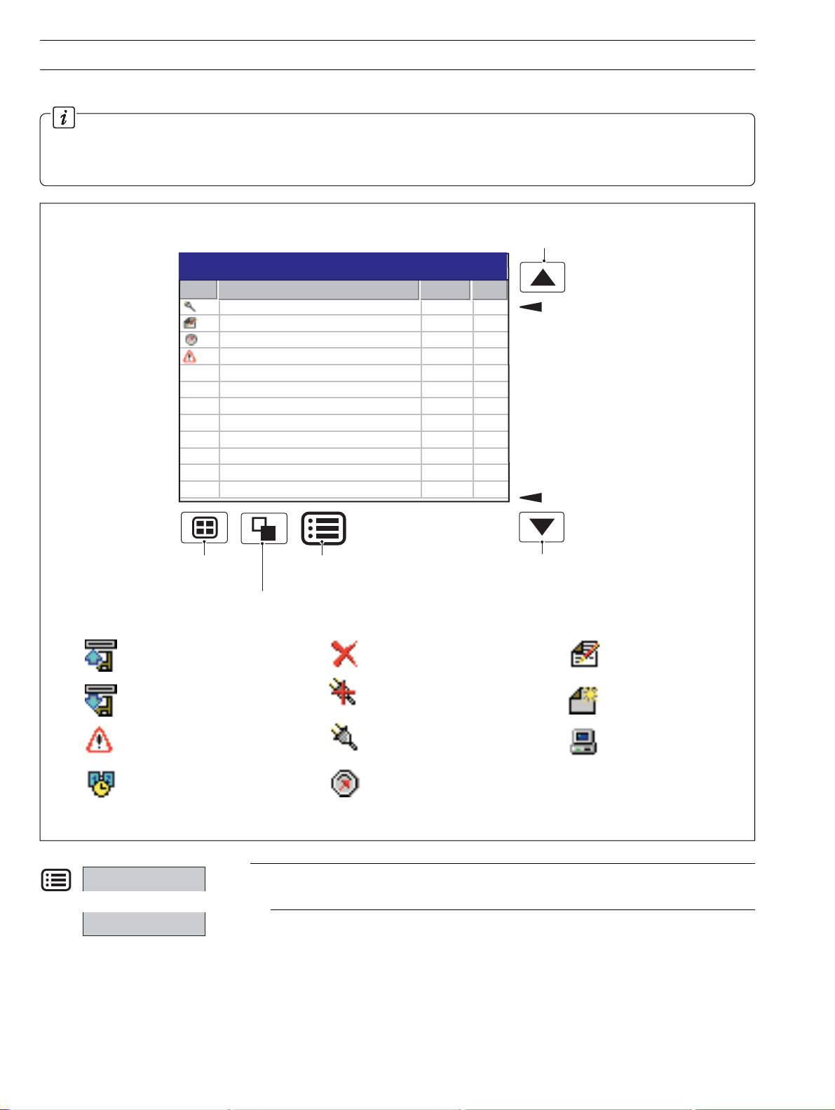
File Viewer
Internal
External
External File Viewer
Name Size
SM2000.cfg 17848
12_10_59 011100 SM2000.cfg 17848
13_09_48 311200 SM2000.cfg 17848
13_59_37 280800 SM2000.cfg 17848
21_49_58 010100 SM2000.cfg 17848
Delete
Use the file viewer to view a list of the files stored in internal memory and on external archive
media.
Note. Files stored in internal memory cannot be deleted.
Exit
24
Page 27
3 SETUP…
3.4 Archiving
Recorded data, logs and configuration files stored on the instrument's internal memory can be archived to files created on removeable
media. Parameters for archiving Process Groups 1 and 2 data are setup independently.
Note. For further information on Archiving refer to Section 4.5.6 – Archiving Configuration.
3.4.1 SmartMedia Handling and Care
Note. The instrument is designed to work only with 3.3V SmartMedia cards.
Follow the manufacturers' recommendations.
1) Avoid touching the gold connectors on SmartMedia cards to prevent damage to the card from static electricity. Before touching
a memory card, ensure that you are discharged of static electricity by touching a grounded metal object.
2) Keep the gold contacts on the card clean to prevent card corruption on insertion of the card. Clean the contacts using a soft, clean
cloth before re-insertion in the instrument.
3) Do not bend the card or subject it to impacts.
4) Keep the card in an anti-static film case when not in use.
5) Do not place the card in direct sunlight.
3.4.2 Media Status – Fig. 3.2
Process Group 1
28/03/00
External archive media on-line
(green icon, shaded area indicates % used)
External archive media off-line
(grey icon, shaded area indicates % used)
Instrument Status
VERSION
CJ TEMPERATURES
°°
°°
28/03/00
External archive media update in progress.
External media 100% full, archiving stopped
ARCHIVING
Amount of memory used on the external archive
media currently installed
(white cross on red background)
Approximate time left before the current external
archive media is full, assuming the amount of data
recorded remains the same.
Time Left Display Format
>=1 Day: Days, e.g. '5 Days'
>=1 Hour, <1 Day: Hours, e.g. '10 hours'
<1 Hour: Minutes, e.g. '25 minutes'
Caution. Do not remove media while the icon (media update in progress) is displayed.
Fig. 3.2 Media Status Icons
25
Page 28
…3 SETUP
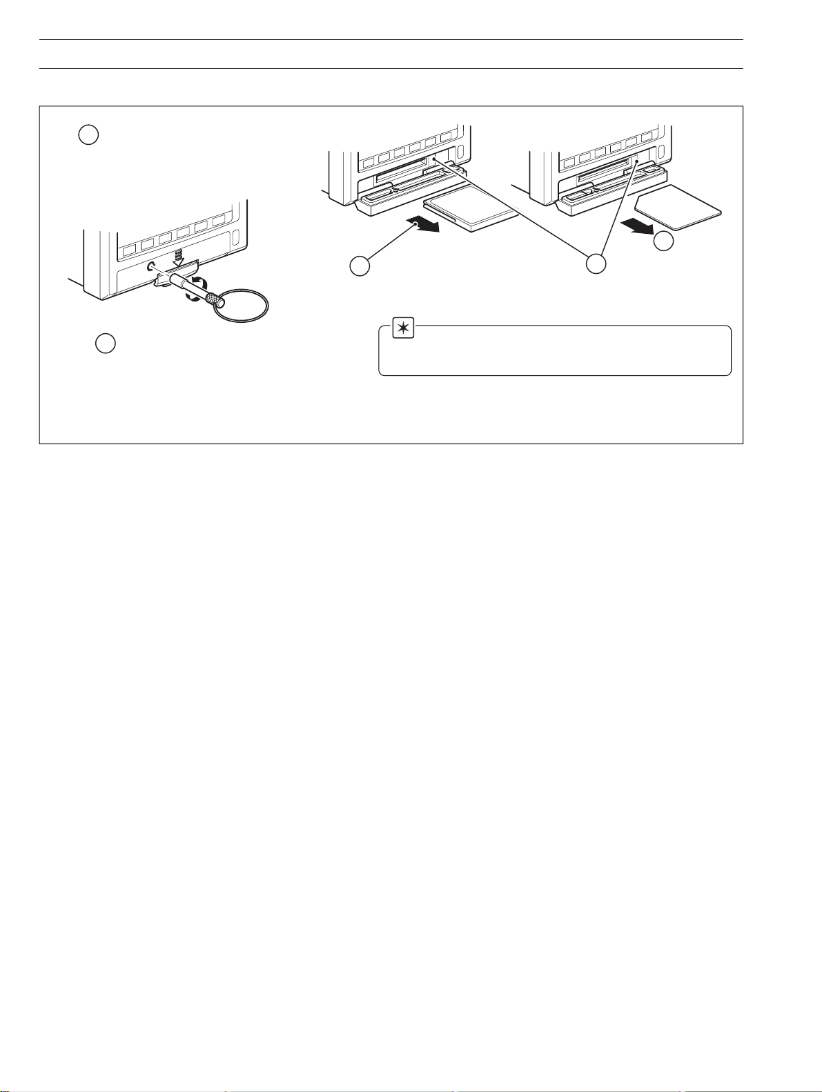
3.4.3 Inserting and Removing Media – Fig. 3.3
1
Ensure that the media is put off-line –
see Section 3.3
4
Withdraw the media
Compact Flash Media SmartMedia
3
Press the eject button
4
Unlock the media door with the key supplied
2
and press the release catch to open the door
Fig. 3.3 Inserting and Removing External Media
Note. When inserting the media into the instrument:
• Ensure that the media is the correct type for the instrument.
• Do not use excessive force.
26
Page 29

3 SETUP…
3.4.4 Archive File Types
Archive files created by the instrument are given filenames
automatically. Each type of archived file is given a different file
extension:
noisnetxE/epyTstnetnoC
/selifatadlennahC
**D.*
/selifgoltnevemralA
**E.*
/selifgolrezilatoT
**T.*
/selifgoltiduA
**A.*
erutangislatigiD
**S.*/selif
)spuorg
.elifatad
puorgssecorptnerruc
.slennahcgnidrocers’puorg
ehtnislennahcgnidrocerlatigidrogolanA
,stnevemralaehtfodrocerlacirotsihehT
.smralaemitlaerrosegassemrotarepoynafo
dnarezilatotllafodrocerlacirotsihehT
ehtotgnitalerseulavlacitsitatsdetaicossa
.goltiduaehtmorfseirtnelacirotsihehT
Note. Totalizer files are created only if the totalizer
option is fitted.
3.4.5 Channel Data Files
Channel data files can be configured to contain data gathered over
a predefined period of time using the 'New File Interval' setting.
lavretnielifweNemaneliF
ylruoH>emanelif<*>raey,htnom,yad<>sruoh<
yliaD.>gatemanelif<*>raey,htnom,yad<
ylhtnoM>gatemanelif<*>raey,htnom<
enoN>gatemanelif<
*nommoCnites'tamrofetaD'ehtotgnidroccadettamroF
Note. The New File Interval is set in the Configuration
level – see Section 4.5.6.
In addition to new files being created according to the New File
Interval selection, they are also created in the following
circumstances if automatic update is enabled and the media is
on-line or if a manually triggered update is in progress:
• The instrument's power is lost then restored.
• The instrument is taken offline and the archive media
removed, replaced or refitted.
• The instrument's configuration is changed.
• One of the current files exceeds the maximum
permissible size.
When one of these conditions occurs, new channel data files are
created for each enabled group and the file extension index on
each new file is incremented by one from the previous file.
Example – if the original file had an extension of .*D00, after one
of the above events a new file will be created with the same
filename but an extension of .D01.
.1.4.4noitceSees–noitarugifnoC
3.4.6 Filename Example
'New file interval' set to hourly, filename tag set to 'Process
Group 1'; date is 10th October 2000; Channel data and alarm
event log files only enabled:
9:00 am New file created in which all channel data recorded
between 9:00 and 9:59:59 is archived in the following
file:
09_00_10Oct00_Process_Group_1.d00
yrotsihehtsulpslennahcs’puorgehtotdetaler
09:12am Power interrupt occurs
09:13am Power restored and new file created:
09_00_10Oct00_Process_Group_1.d01
10:00am New file created in which all data recorded between
llarofemasehtsielifsihtfotnetnoceht:etoN(
10:00 and 10:59:59 is archived.
10_00_10Oct00_Process_Group_1.d01
lennahcgnidnopserrocehtroferutangislatigiD
Note.
• Hourly files start exactly on the hour.
• Daily files start at 00:00:01.
• Monthly files start at 00:00:01 on the first of the month.
3.4.7 Log files
The Alarm Event, Totalizer and Audit Logs are each archived into
one file. The filenames have the following formats, with the date
and the time indicating the first entry in the file:
eliFgoLemaneliF
tnevEmralA00e.>emanelif<*>yy,mm,dd<>nimruoh<
rezilatoT00t.>emanelif<*>yy,mm,dd<>nimruoh<
tiduA00a.>gattnemurtsni<*>yy,mm,dd<>nimruoh<
If one of the archive log files becomes full (>64000 entries) a new
file is created with an extension incremented by 1, e.g. a01, e01
etc.
Note. Totalizer logs are created only if the totalizer
option is fitted.
3.4.8 Online/Offline
Before data can be archived to external media, the external
media must be placed on-line and one or more archive file
enables must be set.
• External archive media is placed on-line automatically
when inserted.
• External archive media is set on-line and off-line in the Set
up menu – see Section 3.3.
•To avoid loss of data, external media must be set off-line
before removal.
Note. Data stored in the internal memory buffer can
still be stored to the archive media when the archive media
is placed on-line again (providing it is not off-line so long that
the un-archived data in the internal memory is overwritten).
noitarugifnoCnommoCnites'tamrofetaD'ehtotgnidroccadettamroF*
27
Page 30

…3 SETUP
3.4.9 Archiving Updates
Data from the instrument's internal memory is archived to
external memory in the following circumstances:
• Automatically, if 'Update type' is set to 'Automatic' during
configuration.
• When the operator selects 'Update' from the Setup menu.
• When a digital signal assigned to the archive update
source becomes active.
If there is un-archived data more than one hour old when
the external media is inserted or placed on-line, or when
'Update' is selected from the Setup menu, the operator is
prompted to select the data to be archived:
Select the amount of data to archive
No historical data
< 1 hour old
< 2 hours old
< 4 hours old
< 8 hours old
< 12 hours old
< 1 day old
< 2 days old
< 3 days old
All historical data
More than 1 hour of
unarchived data has been
detected. Please select the
amount of data to be archived
and press enter.
If a large amount of unarchived data exists, a progress bar
appears. During this time operator views cannot be
accessed, but new data continues to be recorded to the
internal buffer memory.
Updating Archive...
50%
Cancel
3.4.10 File Formats – Figs. 3.4 to 3.7
The archived data is stored in a comma delimited (*.csv) format
so that it can be imported directly in to a standard spreadsheet
– such as Microsoft Excel™ and Lotus 1-2-3™. The files can
also be read as an ASCII text file by a text viewer. When imported
in to a spreadsheet, the files appear as shown in
Figs. 3.4 to 3.7.
3.4.11 Digital Signatures – Fig. 3.4
A digital signature file is created for each channel data file using
the same filename but with a *.S** extension. The file contains a
unique 'fingerprint' of the contents of the data file that can be
used to prove if the data has been tampered with or corrupted.
Data validation can be carried out on a PC using the Company's
DataManager software.
28
Fig. 3.4 Channel Data File Sample
Page 31

Fig. 3.5 Alarm Event Log Sample
3 SETUP
Fig. 3.6 Totalizer Log Sample
Fig. 3.7 Audit Log Sample
29
Page 32

4 CONFIGURATION
4.1 Introduction
This section details the configuration of the instrument locally
using the front panel membrane switches. The instrument can
also be configured on a PC using the configuration software
package. The configuration can then be transferred to the
instrument via the configuration socket, or one of the archive
media options.
In addition, up to 16 different configurations can be stored on
internal memory and restored when required.
4.1.1 Configuration Method
To configure an instrument:
• Access the Configuration Level – see Fig. 4.1.
• Make changes to parameters as detailed in
Figs. 4.2 and 4.3.
Note. The Configuration level cannot be accessed while the Security switch is set to the 'Configuration level
protected' position.
Unscrew the jacking screw
2
securing the instrument to
the case.
Switch off the power to
3
the instrument and
withdraw it from the case
4.1.2 Configuration Access – Figs. 4.1 and 4.2
Access to the Configuration level is determined by the setting of
the security switch and the 'Configuration Security' parameter:
'ytiruceSnoitarugifnoC'
gnitteSretemaraP
)2.4.4noitceSeeS(
drowssaP'
'detcetorP
noitarugifnoC
ytiruceS
hctiwS
gnitteS
)1.4.giFeeS(
Set the position of the yellow Security switch to
4
'Configuration Level Not Protected'
detcetorP
toN
detcetorP
Configuration level protected
Configuration level not protected
drowssaP
sseccA
eerF
sseccA
hctiwS'
'detcetorP
sseccAoN
eerF
sseccA
Remove tamper-proof
1
seal, if fitted
Note. The red switch is for factory use only.
Ensure that it remains in the position closest to the
rear of the instrument.
Fig. 4.1 Setting the Security Switch
Re-apply power to the
5
instrument and wait for
the Operator Level to display
Access the Configuration Level
6
as shown in Fig. 4.2
30
Page 33

…4.1.2 Configuration Access – Figs. 4.1 and 4.2
Operator 1
Configuration
Operator 1
Use the up and down keys to select your password.
Confirm with Enter key
0000
Operator 2
Operator 3
Operator 4
Displayed only if 'Configuration Security'
parameter is set to 'Password Protected'
– see Section 4.4.2
4 CONFIGURATION…
Operator 1
Edit Current Configuration
Open a Configuration
New Configuration
Cancel
Disable recording in configuration
Check this box to stop
recording while in the
configuration mode
Use to highlight
a different selection.
Use to accept the
selection
Cancel and return to the
operator level
Edit the currently active configuration.
Changes are not implemented until saved
on exit from the configuration level
Internal Storage
QSRTD_F
QSRTD_C
QSTHC_F
QSTHC_C
QSFlow
QSMilliamp
QSDemo
Company standard
SM2000
QSDairy
External Storage
Use the key to
switch between internal
and external storage.
Press to cancel.
Open a configuration previously saved
to internal or external archive storage
media (up to 16 configurations can be
stored in internal memory). Alternatively,
open one of the QuickStart templates –
see APPENDIX 4.
Open a new configuration with the default
settings detailed in APPENDIX 4
Common
Group 1
Channels 1.1 - 1.6
Group 2
Channels 2.1 - 2.6
Functions
I/O Modules
Exit
Note. If New Configuration or Open a Configuration is selected and the modified configuration file is later saved as the
current configuration, new internal data files for all enabled recording channels are created and any unarchived data is lost.
Fig. 4.2 Accessing the Configuration Level
31
Page 34

…4 CONFIGURATION
4.2 Overview of Configuration – Fig. 4.3
Common
Group 1
Channels 1.1 - 1.6
Group 2
Channels 2.1 - 2.6
Functions
I/O Modules
Exit
Common Configuration
Setup
Security Logs
Configuration type
Number of groups
Global alarm ack source
Instrument tag
Date & Time
Language
Contrast
Operator Messages
Basic
1
dd mmm yy; hh:mm:ss
English
See Appendix 1
SM1000
6
Select 'Common' from the Configuration menu.
1
Select the required parameter using the
2
and keys.
3
Edit selected parameter by pressing the
key.
Select not required tab using the
4
Common Configuration
Setup
Security Logs
Configuration type
Number of groups
Common
Group 1
Date & Time
Channels 1.1 - 1.6
Group 2
Global alarm ack source
Channels 2.1 - 2.6
Functions
Instrument tag
I/O Modules
Exit
Language
Contrast
Operator Messages
Basic
1
dd mmm yy; hh:mm:ss
English
See Appendix 1
SM1000
6
Press key to display menu. Select the next item
5
required and activate using the
When all configuration changes are complete select
6
Exit to save or cancel changes.
key.
Note. The number of Process Group and Channel Options change to reflect the number of Process Groups that are
currently enabled.
Fig. 4.3 Overview of Configuration Steps
and keys.
32
Page 35

4.2.1 Adjusting Screen Contrast – Fig. 4.4
Common Configuration
Setup
Security Logs
Configuration type
Number of groups
Date & Time
Global alarm ack source
Instrument tag
Contrast
Language
Contrast
Operator Messages
Basic
100
1
dd mmm yy; hh:mm:ss
English
See Appendix 1
0
SM1000
6
1
2
Fig. 4.4 Adjusting Screen Contrast
4.3 Making Changes to Parameters – Figs. 4.5 to 4.7
4 CONFIGURATION…
Adjust the contrast to the required level using the and keys
(0 = darkest and 100 = lightest).
Press the
or
Press the
key to save selected contrast level
key to cancel the selection.
Configuration Tab
Set Up
Parameter
Parameter Value
Broken sensor detection
Note. The appropriate
data entry box is displayed
automatically – see Fig. 4.6.
Channel 1.1
Analog i/p
Engineering range
Fault detect level (%)
Alarm A Totalizer Scales
Input Type
Short tag
Long tag
Filter time constant
Sub-menu
4.0 - 20.0 mA
0 to 20000 Litres/sec
8 Character
20 Characters
In seconds
110%
Upscale
Channel 1.1
Analog i/p A1
Type
Linearizer type
Electrical range low
Electrical range high
Higher-level windows
remain visible to identify
location within the
configuration structure
Selection List
Use to highlight a
different selection.
Use to accept the selection
milliamps
Linear
4.0
20.0
Edit Button
OK
Channel 1.1
Analog i/p A1
Type
Off
Linearizer type
millivolts
Linearizer units
milliamps
Electrical range low
Volts
Resistance
Electrical range high
Resistance thermometer
Thermocouple
Type
4 to 20mA
Linear
None
50.2
5.0
OK
Note. Use the key to select a different channel (see Fig 4.10)
Fig. 4.5 Locating Parameter Settings
33
Page 36

…4 CONFIGURATION
…4.3 Making Changes to Parameters – Figs. 4.5 to 4.7
Tick Box
1. Totalizer reset enable
2. Totalizer stop/go enable
3. Message select enable
4. Alarm acknowledge enable
Note. Items not selected are
indicated by an X in the parameter
window
1 2 X 4
Parameter Limits
Numeric (0.0...1000.0)
999.9
List Box
Use and keys to select
item and
key to toggle
selected item on or off.
OK
Off
millivolts
milliamps
Volts
Resistance
Resistance thermometer
Thermocouple
Highlight text box and use and
keys to insert text at different position.
Flashing Cursor
Use these keys
to navigate and
to select highlighted
item.
Note. Values outside the given
range or with too many decimal places
are highlighted
123.45
Note. Tags with a high percentage of capital letters and wide characters such as 'W' or 'M' may appear truncated in
some Operator Views. In such cases, use lower case letters or fewer characters.
Fig. 4.6 Data Entry Dialog Boxes
Spacebar
34
Page 37

…4.3 Making Changes to Parameters – Figs. 4.5 to 4.7
Common
Group 1
Channels 1.1 - 1.6
Group 2
Channels 2.1 - 2.6
Functions
I/O Modules
Exit
4 CONFIGURATION…
<configuration filename>.cfg
Save as Current Configuration
<configuration filename>.cfg
Internal Storage
External Storage
Save Configuration
Cancel
Process Group 1
Pressure
Level
2.08
metres
010
12:00:00
11:59:00
11:58:00
11:57:00
bar
4
High Level
In Flow
204.9
Out Flow
198.9
l/hr
l/hr
High Out Flow Rate
28/03/00
14:52:00
Alarm 1
Temp
On
195
°C
Note.
• The current, active, configuration is saved on internal storage with the filename 'SM1000.cfg'.
• Selecting 'Save as Current Configuration' causes recording to be suspended for a short time while the new configuration
is implemented.
• When saving the current configuration to internal storage, the file is saved automatically with the 'SM1000.cfg' filename,
and with a <time><date><instrument tag>.cfg filename.
• When saving the current configuration to external storage, the file is saved automatically to internal storage with the
'SM1000.cfg' filename, as well as to the external archive media as <time><date><instrument tag>.cfg.
• When 'Save Configuration' is selected the configuration file is stored as <time><date><instrument tag>.cfg on internal or
external storage.
• Changes are saved to non-volatile memory only when one of the save options above has been selected. Any powerdown
before this results in lost configuration changes.
• Selecting 'Cancel' causes unsaved changes to be discarded and returns the instrument to the Operating Level.
Caution.
New internal data files for enabled recording channels are created if any of the following configuration parameters have been
changed: Recording channel source; Primary sample rate; Secondary sample rate; Primary/secondary sample rate source;
Input filter type; Engineering range; Channel tag. Any unarchived data is lost.
Fig. 4.7 Exiting Configuration Mode
35
Page 38

…4 CONFIGURATION
4.4 Common Configuration
Common
Group 1
Channels 1.1 - 1.6
Group 2
Channels 2.1 - 2.6
Functions
I/O Modules
Exit
4.4.1 Setup
Common Configuration
Setup
Security Logs
Configuration type
Number of groups
Global alarm acknowledge
Instrument tag
Date & time
Language
Operator Messages
Basic
1
dd/mmm/yy; hh:mm:ss
English
See Appendix 1
SM 2000
Fig. 4.8 Selecting Common Configuration
Setup
Security Logs
Configuration Type
Number of Groups
Date and Time
Operator Messages
Configuration type
Basic
Fixed as Basic
Enter the number of Process Groups required.
1
Each Process Group has 6 recording channels pre-assigned
to it – Group 1 (Ch1.1 to 1.6), Group 2 (Ch2.1 to 2.6).
If the Number of Groups is changed from 2 to 1,
configuration data for Process Group 2 is retained but not
used.
Set the current date and time.
28/03/00; 12:00:45
36
Caution. Setting an earlier time or date results in all
data currently in the internal buffer memory past that date
being lost. If you wish to retain this information, make sure it
has been stored to external archive media prior to changing
the time or date – see 'Update', Section 3.3.
Note. Changes to the date and time are effective
immediately, not when the configuration is saved.
Page 39

...4.4.1 Setup
4 CONFIGURATION…
Language
Global Alarm Ack Source
Instrument tag
4.4.2 Security
Setup Logs
Security
User 1
User 2
User 2
English
None
SM1000
Operator Messages
Operator 1
Operator 2
Name
Password
Operator 2
****
Select the language to be used to display standard user
prompts and menu items.
A digital source can be used to acknowledge active alarms in
both Process Groups 1 and 2. Refer to APPENDIX 1 for a full
list of sources available.
Enter the tag to be used to identify the instrument on
configuration and audit log files.
Change the user name and password used to access the
configuration level when 'Password protection' is enabled –
see below.
Note. User 1 has 'administrator' type priviledges
allowing them to change any of the user names and
passwords. Other users can change only their own user
name and password. For users 2, 3 and 4 access can be
enabled or disabled. If it is disabled then the configuration
levels cannot be accessed using that user name.
When a change to the instrument's configuration occurs, the
user's ID is added to the audit log entry.
User 3
User 4
Configuration security
Setup level security
Setup Level Password
Access
Enabled
Operator 3, No access
Operator 4, No access
Password protected
On
****
OK
Set the method of access to the Configuration level. If
'Password protected' is selected, access is by means of the
password set above.
Note. If 'Switch protected' is selected, access to the
Configuration level for all users is prohibited once the
changes have been saved and made active. Access to the
configuration level can then be achieved only by setting the
security switch to the 'Configuration not protected' position
– see Fig. 4.1.
When set to 'On', access to the Setup level is protected by a
single password for all users.
Displayed only when Setup Level Security is set to 'On'
37
Page 40

…4 CONFIGURATION
4.4.3 Logs
Setup Security
Logs
Operator Messages
Set the maximum number of entries in each instrument log.
Alarm Log Size
Totalizer Log Size
Audit Log Size
200
200
200
4.4.4 Operator Messages
Setup Logs
Security
Message 1
Message 2
Operator Messages
20 Characters
20 Characters
Note. Changing the log size results in the current log
entries being deleted.
Alarm Event log records all process alarm transitions
The
(inactive to active, unacknowledged to acknowledged or
active to inactive), real-time events and Operator Messages
– see Section 2.7
Totalizer log records all activity associated with the
The
totalizers: start, stop, reset, wrap, current total and
intermediate totals – see Section 2.8.
Audit log records all system changes and events – see
The
Section 2.9.
Log sizes must be set in the range 10 to 200. The size of the
logs has no effect on the amount of memory available for
storing channel data.
Operator Messages can be triggered via the Operator
Menus or a digital signal.
Message 3
Message 4
Message 5
Message 6
Operator Message 1
Source ID
20 Characters
20 Characters
20 Characters
20 Characters
Message 1
Tag
None
Tag
Enter the message text – 20 characters maximum.
Source ID
Select the internal or external source used to add the tag to
the Alarm Event log.
OK
38
Page 41

4.5 Process Group Configuration
Common
Group 1
Channels 1.1 - 1.6
Group 2
Channels 2.1 - 2.6
Functions
I/O Modules
Exit
Note. If only one Process Group has been selected in the common configuration setup, only one Process Group is
displayed in the configuration menu.
Process Group 1
or
Process Group 2
Recording
Recording enable source
Primary sample rate
Secondary sample rate
Sample rate select source
Fig. 4.9 Selecting Process Group Configuration
4 CONFIGURATION…
Group Configuration
Chart Bar Process Digital Archive
20 Characters
Tag
On, Off
MM:SS
MM:SS
None
4.5.1 Setting the Recording Parameters
Recording
Recording enable source
Chart Bar Process Digital Archive
20 Characters
Tag
None
Enter the Process Group tag that appears in the title bar
when any operator views from that group are displayed.
Set the edge-triggered digital source (e.g. Alarm Signal,
Real-time Event) used to enable/disable recording of all
channels in the group.
DisabledEnabled
39
Page 42

…4 CONFIGURATION
...4.5.1 Setting the Recording Parameters
Primary sample rate
mm:ss
•1
Set the rate at which all recording channels in the group are
sampled and stored to internal memory. This is also the time
interval between samples stored on archive media, if
archiving is enabled.
Note. If a sample rate of less than 1s is selected then
the time interval between samples stored on archive media is
set to 1s.
etaRelpmaS
s1
s3
s6
s21
s63
s27
trahCtnelaviuqE
deepS
h/mm027
h/mm042
h/mm021
h/mm06
h/mm02
h/mm01
egarotSdraob-nO
)slennahC6(emiT
sruoh7.22
syad8.2
syad7.5
syad5.11
shtnom1.1
shtnom3.2
Note 1. Sample rates must be set using one of the
following combinations of units:
• Minutes or minutes and seconds
• Seconds
•Tenths of seconds (minutes and seconds must first be
set to zero).
Note. The rate at which data is displayed in the Chart
View (the screen interval) is set separately – see
Section 4.5.2.
Secondary sample rate
Sample rate select source
mm:ss
None
Note. The sample rate determines the maximum
screen interval that can be selected.
etaRelpmaS
gnitteS
s1<setunim9otpUsetunim31otpU
s01ot1ruoh1otpUsruoh5.1otpU
s02<,s01>sruoh21otpUsruoh81otpU
s04ot02yad1otpUsyad5.1otpU
s06ot04yad2otpUsyad3otpU
s041<,s06>syad3otpUsyad5.4otpU
s041>syad7otpUsyad01otpU
weiVtrahClacitreVweiVtrahClatnoziroH
Primary and Secondary sample rates allow a slow rate to be
•1
selected for normal conditions and a faster rate for abnormal
alarm conditions in order to record the maximum amount of
detail. The sample rate is selected by the sample rate source
– see following parameter.
Set the digital source (e.g. alarm signal, real-time event) used
•1
to switch between the primary and secondary sample rates.
PrimarySecondary
Edge-triggered signal
lavretnIneercSxaM
•1 A new internal data file for all the recording channels in this group is created if this parameter is changed. All historical data stored
internally for these channels will be lost.
40
Page 43

4.5.2 Configuring the Chart Display
Major Chart Divisions
4 CONFIGURATION…
Minor Chart Divisions
Scale Bar
Chart Trace
Time Stamp
Operator Message
Annotation
Alarm Event
Annotation
195
28/03/00
12:00:45
Alarm 1
°C
On
Screen Interval
Group 1
In Flow
204.9
4
bar
2.08
metres
Pressure
Level
010
12:00:00
11:59:15
11:58:30
11:57:45
Out Flow
198.9
l/hr
12:00:30 High Out Flow Rate
11:58:53 Duty/Standby Switched
11:58:00 High Level
Temp
l/hr
Chart Divisions
Process Group 1
12:00:30 High Out Flow Rate
11:58:53 Duty ON, Standby OFF
28/03/00
12:00:45
Level
Pressure
In Flow
204.9
Out Flow
11:58:00 High Level
2.08
metres
198.9
4
bar
l/hr
l/hr
Recording
Chart view enable
Chart annotation
Major chart divisions
Minor chart divisions
Chart
Bar Process Digital
Vertical
None
4
0
12:00:00
010
11:59:15
11:58:30
Screen Interval
Archive
Alarm 1
12:00:00
11:57:45
11:57:00
11:56:15
On
Select the Horizontal or Vertical chart view.
Select the annotations displayed on the chart. Alarm events
and operator messages are displayed on the chart adjacent
to the point at which the alarm occurred – see Section 2.3.
This initial setting can be changed by the operator if 'Chart
annotation select enable' is enabled in the Chart view menu
enables – see 'Menu Enables' opposite.
Set the number of major vertical divisions to be displayed on
the scale bar and the chart.
Set the number of minor vertical divisions to appear between
the major chart divisions on the scale bar.
41
Page 44

…4 CONFIGURATION
…4.5.2 Chart
Screen interval
Menu enables
Chart menu enables
1. Message select enable
2. Alarm acknowledge enable
3. Scale select enable
4. Trace select enable
5. Screen interval select enable
6. Historical review enable
7. Chart annotation select enable
3 minutes/screen
1 2 3 X 5 6 X
OK
Set the amount of historical data displayed on the screen.
Limits are enforced according to the sample rate selected:
etaRelpmaS
gnitteS
s1<setunim9otpUsetunim31otpU
s01ot1ruoh1otpUsruoh5.1otpU
s02<,s01>sruoh21otpUsruoh81otpU
s04ot02yad1otpUsyad5.1otpU
s06ot04yad2otpUsyad3otpU
s041<,s06>syad3otpUsyad5.4otpU
s041>syad7otpUsyad01otpU
weiVtrahClacitreVweiVtrahClatnoziroH
lavretnIneercSxaM
Select the menu items to be accessible from the Chart View.
Message select enable
Allows the operator to activate one of six pre-configured
messages.
Alarm acknowledge enable
Allows the Operator to acknowledge any alarms associated
with the current group.
Scale select enable
Allows the operator to display the scale for one enabled
channel, or all channels in turn, on the scale bar at the top of
the screen.
Trace select enable
Allows individual chart traces to be displayed or hidden.
Screen interval select enable
Allows the Operator to change the amount of data displayed
on the screen at one time.
Historical review enable
Allows the Operator to scroll back through previously
recorded data that is no longer visible on screen.
Chart annotation select enable
Allows the display of Alarm events and Operator messages
on the chart to be enabled or disabled by the operator.
Note. Menu items that are not enabled appear greyed-
out on the Chart View menu.
42
Page 45

4.5.3 Configuring the Bargraph display
Group 1
Level
2.08
metres
Alarm Trip Level
(not shown for slow and
fast rate alarms)
Maximum Value
(solid color)
Instantaneous Value
Minimum Value
(white fill)
5.0
2.5
Pressure
4 CONFIGURATION…
28/03/00
14:52:00
195
250
125
Alarm 1
On
°C
Engineering High Value
Engineering Middle Value
Temp
l/hr
300
150
300
150
Out Flow
198.9
l/hr
In Flow
204.9
4
bar
5.0
2.5
Recording
Chart
Bar graph view enable
Bar graph markers
Menu enables
Bar graph menu enables
1. Message select enable
2. Alarm acknowledge enable
3. Max/min reset enable
Bar
Process Digital Archive
Horizontal
Max, Min and Alarm Trips
1 2 3
0.0
Analog Channels
0.0
0
0.0
0
Engineering Low Value
Digital
Channel
Identical Maximum
and Minimum
Values
Minimum below
engineering limit,
maximum above
engineering limit
Select the Bargraph views that can be displayed in the
current Process Group.
Select the markers (channel-colored max./min. indicators
and alarm trip points) to be displayed on the bargraph.
Select the menu items to be accessible from the Bargraph
views.
Message select enable
Allows the Operator to activate one of six pre-configured
messages.
Alarm acknowledge enable
Allows the Operator to acknowledge any alarms associated
OK
with the current group.
Max/min reset enable
Allows the operator to reset the maximum and minimum
values of one or more channels to the current value.
Note. Menu items that are not enabled appear greyed
out on the Bargraph menu.
43
Page 46

…4 CONFIGURATION
4.5.4 Configuring the Process View
Note. This view is displayed only if the Totalizer option is fitted.
Alarms View – Totalizer Enabled
Totalizer Tag Name
Total Daily In Flow
0005402801
Totalizer Value
Statistics View – Totalizer Enabled
Total Daily In Flow
0005402801
litres
litres
Low In Flow Rate
High In Flow Rate
Alarm
Ta g
Channel Long Tag Name
Storage Tank 1 In Flow
225.4 110.9 201.0
40
280
Alarm Trip
Level
In Flow
204.9
In Flow
204.9
Alarm Acknowledged
l/hr
l/hr
Recording
Chart
Process view enable
Totalizer view select
Menu enables
Process view enables
Alarms View or Statistics View – Totalizer not Enabled
Alarms View – Alarms A and B not Enabled
Total Daily In Flow
0005402801
Process
Bar Digital Archive
On
Statistics
1 2 3 X X
1. Message select enable
2. Alarm acknowledge enable
3. Totalizer reset enable
4. Totalizer stop/go enable
5. View select enable
Max
Values since last Totalizer Reset or Totalizer wrap.
Updated only if the Totalizer is Enabled and Running.
Low In Flow Rate
High In Flow Rate
Storage Tank 1 In Flow
litres
Min
Average
40
280
In Flow
204.9
In Flow
204.9
Set to 'On' to allow the operator to display the Process View.
Select the Totalizer View to be displayed – Alarms or
Statistics. This setting can be changed by the Operator if
'View select enable' is ticked below.
Select the menu items to be accessible from the Process
View.
Message select enable
Allows the Operator to activate one of six pre-configured
messages.
Alarm acknowledge enable
allows the Operator to acknowledge any alarms associated
with the current group.
Totalizer reset enable
Allows the Operator to reset the totalizers on any or all
channels.
OK
Totalizer stop/go enable
Allows the Operator to stop and start totalizers on any or all
channels.
View select enable
Allows the Operator to select the Alarms and Statistics views.
l/hr
l/hr
44
Note. Menu items that are not enabled appear greyed-
out on the Process View menu.
Page 47

4.5.5 Digital Indicator View
4 CONFIGURATION…
Short Channel Tag
Current Value
Alarm Status
Units
Recording
Totalizer display enable
Chart
Digital view enable
Group 1
Level
Level
2.08
2.08
578494
578494
metres
metres
m
m
In Flow
204.4
0005402801
l/hr
m
Temp
195
Bar Process Archive
On
On
Digital
°C
m
3
3
3
3
Pressure
Out Flow
198.4
0005402060
Alarm 1
On
28/03/00
14:52:00
4
2.08
578494
metres
3
m
l/hr
3
m
bar
Channel Units
To ta lizer Units
To ta lizer Value
Note. Displayed only if
totalizer option is fitted and
totalizers enabled for display.
Set to 'On', to allow the Digital Indicator View to be selected
for display by the operator.
Note. This view is displayed only if the Totalizer option
is fitted.
Menu enables
Digital menu enables
1. Message select enable
2. Alarm acknowledge enable
3. Totalizer reset enable
4. Totalizer stop/go enable
5. Channel select enable
1 2 3 4 5
OK
Set to 'On' to add the channel totalizer value and units to the
indicator displays (if the totalizer for that channel is enabled).
Select the menu items to be accessible from the Digital Indicator
view.
Message select enable
Allows the Operator to activate one of six pre-configured
messages.
Alarm acknowledge enable
Allows the Operator to acknowledge any alarms associated
with the current group.
Totalizer reset enable
Allows the Operator to reset the totalizer value to the preset
totalizer value on any or all channels.
Totalizer stop/go enable
Allows the Operator to start and stop the totalizer.
Channel select enable
Allows the Operator to display or hide individual channels.
Notes.
• Menu items that are not enabled appear greyed-out on
the Digital Indicator View menu.
•Totalizer menu options can be enabled only if the totalizer
option is fitted.
45
Page 48

…4 CONFIGURATION
4.5.6 Archiving Introduction
Recorded data, logs and configuration files stored in the
instrument's internal memory can be archived to files created in
removeable media. Parameters for archiving Process Group 1
are setup independently from Process Group 2 parameters.
File Formats
The archived data is stored in a comma separated file ('.csv')
format so that it can be imported directly in to a standard
spreadsheet – such as Microsoft Excel and Lotus 1-2-3. The
files may also be read as an ASCII text file by a text viewer – see
Section 3.4.
Archiving Updates
Saving data to the removable archive media can be triggered in
a number of ways:
• Automatic update (archive update type set to automatic on
archive configuration).
• Update request selected from the setup menu.
• Digital signal assigned to the archive update source in
configuration.
Archive File Types
Archive files created by the instrument are given filenames
automatically. Each type of archive file is given a different
filename extension:
noisnetxE/epyTstnetnoC
/selifatadlennahC
**D.*
/selifgoltnevemralA
**E.*
/selifgolrezilatoT
**T.*
/selifgoltiduA
**A.*
erutangislatigiD
**S.*/selif
)spuorg
.elifatad
puorgssecorptnerruc
.slennahcgnidrocers’puorg
ehtnislennahcgnidrocerlatigidrogolanA
,stnevemralaehtfodrocerlacirotsihehT
.smralaemitlaerrosegassemrotarepoynafo
dnarezilatotllafodrocerlacirotsihehT
ehtotgnitalerseulavlacitsitatsdetaicossa
.goltiduaehtmorfseirtnelacirotsihehT
Note. Totalizer files are created only if the totalizer
option is fitted.
Channel Data Files
Channel data files can be configured to contain data gathered
over a predefined period of time:
lavretnielifweNemaneliF
ylruoH>emanelif<*>raey,htnom,yad<>sruoh<
yliaD.>gatemanelif<*>raey,htnom,yad<
ylhtnoM>gatemanelif<*>raey,htnom<
enoN>gatemanelif<
*nommoCnites'tamrofetaD'ehtotgnidroccadettamroF
In addition to new files being created according to the New File
Interval selection they are also created under the following
conditions if an automatic update is enabled and the media is
on-line or a manually-triggered update is in progress:
• The instrument's power is lost then restored.
• The instrument is taken offline and the archive media
removed, replaced or refitted.
.1.4.4noitceSees–noitarugifnoC
• The instrument's configuration is changed.
• One of the current files exceeds the maximum permissible
size.
• Historical review mode is accessed.
If one of these conditions occurs, new channel data files are
created (for each enabled Process Group) and the extension
index on each new file is incremented by one from the previous
file. Example – if the original file had an extension of .*D00, after
one of the above events a new file is created with the same
filename but with an extension of .D01.
Log files
The Alarm Event, Totalizer and Audit Logs are each archived into
one file. The filenames have the following formats, with the date
and the time indicating the first entry in the file:
eliFgoLemaneliF
tnevEmralA00e.>emanelif<*>yy,mm,dd<>nimruoh<
rezilatoT00t.>emanelif<*>yy,mm,dd<>nimruoh<
tiduA00a.>gattnemurtsni<*>yy,mm,dd<>nimruoh<
Note. Totalizer logs are created only if the totalizer
option is fitted.
If one of the archive log files becomes full (>64 000 entries) a new
file is created with an extension incremented by 1, e.g. a01, e01
etc.
Digital Signatures
A digital signature file is created for each channel data file using
yrotsihehtsulpslennahcs’puorgehtotdetaler
the same filename but with a *.S** extension. The file contains a
unique 'fingerprint' of the contents of the data file that can be
used to prove if the data has been tampered with or corrupted.
Data validation can be carried out on a PC using the Company's
DataManager software.
Data Verification and integrity
llarofemasehtsielifsihtfotnetnoceht:etoN(
When data is saved to the archive media it is checked
lennahcgnidnopserrocehtroferutangislatigiD
automatically to verify that the date value stored on the media
matches exactly what is stored in the internal memory.
Backing up Archived Data
It is advisable to back-up critical data stored on SmartMedia or
Compact Flash cards on a regular basis. The instrument's
internal memory provides a buffer for the most recent data so if
data stored on archive media is lost, it can be re-archived – see
Reset Archiving on page 23.
To ensure that all required data is available for re-archiving, it is
recommended that data archived on archive media is removed
and backed-up before the instrument's internal buffer
overwrites that data. The amount of time that data remains in the
instrument's internal memory depends on the sample rate and
the number of channels selected. See Table A3.1 on page 79 for
details.
noitarugifnoCnommoCnites'tamrofetaD'ehtotgnidroccadettamroF*
46
Page 49

epyTeliFstnetnoCnoisnetxE
atadlennahC
selif
lennahcgnidrocerlatigidrogolanA
puorgssecorptnerrucehtnislangis
00D.*
tnevemralA
selifgol
mralaehtfodrocerlacirotsihehT
slennahcs’puorgehtotdetalerstneve
rotarepoynafoyrotsihehtsulp
.smralaemitlaerrosegassem
00E.*
golrezilatoT
selif
dnarezilatotllafodrocerlacirotsihehT
otgnitalerseulavlacitsitatsdetaicossa
.slennahcgnidrocers’puorgeht
00T.*
selifgoltiduA.goltiduaehtniseirtnelacirotsihehT00A.*
lavretnIeliFweNemaneliF
ylruoH>emanelif<*>raey,htnom,yad<>sruoh<
yliaD.>gatemanelif<*>raey,htnom,yad<
ylhtnoM>gatemanelif<*>raey,htnom<
enoN>gatemanelif<
*nommoCnites'tamrofetaD'ehtotgnidroccadettamroF
.1.4.4noitceSees–noitarugifnoC
4 CONFIGURATION…
…4.5.6 Archiving
Sample Rates – Fig. 4.10
Data is saved to the archive file at the same rate as it is saved to internal memory i.e. at either the group's primary or secondary
recording sample rate.
Recording
Chart Bar Process Digital
Archive file enables
Archive file enables
Primary
rate
Secondary
rate
Group Sample
Rate
Archive
*.d, *.e, *.t, *.a
1. Channel data file enable (*.d)
2. Alarm event log file enable (*.e)
3. Totalizer log file enable (*.t)
4. Audit log file enable (*.a)
Internal Memory
1.1
1.2
1.3
1.4
1.5
1.6
Recording
Channels
Archive Media
Archive
Channel
Archive rate is always
same as channel
sample rate. Archive
channel data is a direct
copy of channel data on
internal memory
Fig. 4.10 Archiving Sample Rates
Select the data types that are to be archived to the storage
media: Channel Data; Alarm Event Log; Totalizer Log; Audit Log.
Note. The Audit log can be archived only with Process
Group 1 files.
Note. The totalizer log file can be enabled only if the
totalizer option is fitted.
Data
Filename tag
New file interval
20 Characters
Off, Hourly, Daily, Monthly
OK
Enter the filename that will be used to identify the instrument
to which the archive files belong.
Note. The following characters cannot be used in the
filename tag: \, /, :, *, ?, ", <, >, |, superscript characters, ~,
Ω and º. These are greyed-out on the keyboard.
Set the frequency with which new channel data files are
created.
47
Page 50

…4 CONFIGURATION
…4.5.6 Archiving
Archive Update
ro
.)'etadpU
.)'etadpU
Archive Update
Update type
Digital update source
etadpucitamotuA
langislatigiD
Man, None
Select the archiving trigger and the interval – see Table 4.2.
Update type
Manual
The frequency with which data is copied from the
instrument's internal memory to the removeable storage
None
OK
media.
Digital update source
The digital update source is used to archive all unarchived
data from the instrument's internal memory to the
removeable media.
ataDdevihcra-nUtsedlO
sreggirTevihcrAdlOyaD1<dlOyaD1>
.unemputeSehtmorftseuqer'etadpU'
.unemputeSehtmorftseuqer'enilnO'
evihcrA'ees–noitarugifnoCgnirudtes(
evihcrA'ees–noitarugifnocgniruddengissa(
.)s03yreve
.evihcra
.aidemevihcraelbavomereht
otyllacitamotuaderotssiataddevihcra-nuynA
elbavomerotdevassiataddevihcra-nuynA
.xorppa(slavretninoitalugertaaidemevihcra
elbavomerotdevassiataddevihcra-nuynA
.A/N
.aidemevihcra
detcelesehtnihtiwataddevihcra-nuehtllA
ataddevihcra-nuredlO.devihcrasiemarfemit
litnureffubyromemlanretniehtnisniamer
ebtonlliwtubatadrewenybnettirwrevo
.aidemelbavomerotgnivihcrarofelbaliava
elbavomerotdevassiataddevihcra-nullA
Table 4.1 Archive Triggers
48
Page 51

4.6 Channel Configuration
Common
Group 1
Channels 1.1 - 1.6
Group 2
Channels 2.1 - 2.6
Functions
I/O Modules
Exit
Process Group 1,
Channels 1.1 to 1.6
1.1
1.2
1.3
1.4
1.5
1.6
Setup
Setup
Setup
Channel 1.1
Analog i/p
Input Type
Channel 1.2
Analog i/p
Input Type
Channel 1.6
Analog i/p
Input Type
4 CONFIGURATION…
Alarm A Totalizer Scales
Alarm B Totalizer
4 to 20 mA, Linear
Alarm A Totalizer Scales
Alarm B Totalizer
4 to 20 mA, Linear
Alarm A Totalizer Scales
Alarm B Totalizer
4 to 20 mA, Linear
Fig. 4.11 Recording Channel Configuration
49
Page 52

…4 CONFIGURATION
4.6.1 Recording Channel Setup
Setup
Source ID
Trace colour
None
Red
•1
Select the signal source for the selected channel. This can be
any external analog or digital signal. See APPENDIX 1 for full
list.
Note. The tabs change according to selection.
Alarm A Alarm BAnalog i/p A1 TotalizerSetup
Source ID
Analog i/p A1
A – Analog Source
Comms Dig i/p 1 TotalizerSetup
Source ID
Comms Dig i/p 1
B – Digital Source
The trace color cannot be changed. The trace colors are:
1st 2nd 3rd 4th 5th 6th
Magenta Red Black Green Blue Brown
•1 If this parameter is changed, a new internal data file for this recording channel is created. All historical data stored internally for this
channel is lost.
50
Page 53

…4.6.1 Recording Channel Setup
Filter type
Instantaneous
4 CONFIGURATION…
Select the filter to be applied to the electrical input prior to
sampling.
•1
Notes.
• Applicable to analog sources only.
• Filters are applied to the recorded values shown on the
chart view only, not to instantaneous values displayed on
the channel indicators or bargraphs.
Raw
Input
Value
100
Sample Interval
0
12:00:00
(Previous
Sample)
Max.Value over sample interval
Instantaneous Value at time of sample
Avg. Value over sample interval
Min.Value over sample interval
t
12:00:01
(Current
Sample)
Instantaneous – A single value based on process
conditions at the time of sampling.
Average – The average value of the analog signal
since the previous sample.
Minimum – The minimum value of the analog signal
since the previous sample.
Maximum – The maximum value of the analog signal
since the previous sample.
Max/Min – Two values are recorded to capture the
maximum & minimum signal values since
the previous sample. This allows the
memory use to be extended by permitting
a slower sample rate to be selected
without losing the transient behaviour of
the signal.
•1 If this parameter is changed, a new internal data file for this recording channel is created. All historical data stored internally for this
channel is lost.
51
Page 54

…4 CONFIGURATION
4.6.2 Analog Input Configuration
Note.
• This tab is displayed only if the Source ID is set to an analog signal – see Section 4.6.1.
• If an analog input is assigned to more than one recording channel, changes to any of its parameters and tags are applied to
each channel the input is assigned to.
• If an analog input is already assigned to another channel, the edit keys are not available.
Setup
Analog i/p A1
Analog i/p A1
Input type
Linearizer Type
Linearizer units
Alarm A TotalizerAlarm B
4 – 20mA
milliamps
Type
Linear
Degrees C
Set the electrical characteristics of the input.
Note. Simulated input types have been made available
for evaluating instrument features without the need for
process connections.
Caution. Ensure that the appropriate electrical
connections have been made. An optional external voltage
divider (part no. GR2000/0375) is required for operation when
this parameter is set to 'Voltage' – see Section 5.4. Voltages
under 2V can be measured without a divider using the milliVolt
range. An external shunt is required for current ranges – see
Section 5.4.
Select the linearizer type and the units used to condition the
input signal before it is sampled.
Notes.
• For thermocouple applications using an external fixed cold
junction, select 'mV' input type and the appropriate
linearizer type.
• Linearizer Units are displayed only if a temperature
linearizer type (Thermocouple or RTD) is selected.
Electrical range low
Electrical range high
5.2
52.0
OK
Notes.
• mA, mV, V or Resistance input types only.
• An optional external voltage divider (part no.
GR2000/0375) is required on each channel where the
'Input type' parameter (above) is set to 'Voltage' – see
Section 5.4. The electrical range low and high should be
set to the actual voltage applied to the divider, not the
voltage after it has been divided down.
The range of the electrical input signal is determined by the
input type:
Input
Type
Min.
Max.
Standard Inputs
mV mA Ω
V
000
0
2000 50 5000
20
Limits of Electrical Ranges
52
Page 55

…4.6.2 Analog Input Configuration
4 CONFIGURATION…
Engineering range
Engineering range
0 to 2000 l/sec
2000
High
0
Low
l/sec
Units
OK
•1
Specify the display range and units of the engineering value
corresponding to the electrical high and low values, within
the limits defined below:
THC/RTD Type
Type B
Type E
Type J
Type K
Type L
Type N
Type R&S
Type T
Pt100
Power 5/2
Power 3/2
SqRoot
Custom
Linearizer 1
Custom
Linearizer 2
Linear
Limits of Engineering Ranges
°C °F
Min. Max. Min. Max.
–18 1800 0 3270
–100 900 –140 1650
–100 900 –140 1650
–100 1300 –140 2350
–100 900 –140 1650
–200 1300 –325 2350
–18 1700 0 3090
–250 300 –400 570
–200 600 –325 1100
–999 to +9999
Example – for an electrical input range of 4.0 to 20.0 mA,
representing a pressure range of 50 to 250 bar, set the 'Low'
value to 50.0 and the 'High' value to 250.0.
Short tag
8 Character
•1
Enter the tag name to be displayed on channel indicators and
used to identify the channel in archive files. (8 characters max.).
Note. Tags with a high percentage of capital letters
and wide characters such as 'W' or 'M' may appear
truncated in some Operator Views. In such cases, use lower
case letters or fewer characters.
Long tag
20 Characters
•1
Enter the tag name to be displayed on the process view and used
in the archive files (20 characters max.).
•1 If this parameter is changed, a new internal data file for this recording channel is created. All historical data stored internally for this
channel is lost.
53
Page 56

…4 CONFIGURATION
…4.6.2 Analog Input Configuration
Filter time constant
Fault detect level (%)
In seconds
10%
Set the time period over which the process variable is to be
filtered prior to being sampled (0 to 60 seconds).
Set a tolerance level (between 0 and 100% of the
engineering range) to allow for deviation of the input signal
above or below the input span before an input failure is
detected.
Example – setting the fault detection level to 10% on an input
range of 50 to 250 bar causes an 'Analog Input Failure' fault
to be detected below 30 bar and above 270 bar.
In the event of an input failure, recorder channels can be set
Broken sensor direction
Upscale
to drive upscale, downscale or in the direction of failure.
Upscale – channel value driven beyond full scale.
None – driven in direction of failure.
Downscale – channel value driven below zero.
4.6.3 Digital Input Configuration
Note. This tab is displayed only if the Source ID for this Recording Channel is a digital source – see Section 4.6.1.
Set Up
Digital I/P
Digital ON tag
Totalizer
Closed
Enter the tag to be displayed on channel indicators when the
•1
digital signal is active (6 characters max.) .
Digital OFF tag
Full
Note. Tags with a high percentage of capital letters
and wide characters such as 'W' or 'M' may appear
truncated in some Operator Views. In such cases, use lower
case letters or fewer characters.
Enter the tag to be displayed on channel indicators when the
•1
digital signal is inactive (6 characters max.).
•1 If this parameter is changed, a new internal data file for this recording channel is created. All historical data stored internally for this
channel is lost.
54
Page 57

4.6.4 Alarm Configuration
4 CONFIGURATION…
Trip Point
Process
Variable
Alarm On
Alarm Off
Trip Point
Process
Variable
Hysteresis
Hysteresis
High Process
Low Process
Fig. 4.12 High/Low Process Alarms
Hysteresis
Alarm On
High Latch Alarm Action
Alarm Latched
Alarm acknowledged
by operator
Alarm On
Alarm Off
Alarm Off
Process
Variable
Trip Point
Hysteresis
Alarm On
Low Latch Alarm Action
Alarm Latched
Alarm acknowledged
Fig. 4.13 High/Low Latch Alarms
Alarm Off
by operator
55
Page 58

…4 CONFIGURATION
…4.6.4 Alarm Configuration
Trip Point
Hysteresis
Process
Variable
Alarm On
Process
Variable
Hysteresis
Trip Point
Alarm On
Deviation Abt exceeded –
low rate alarm becomes
active, new period starts
Deviation
High Rate Alarm
Alarm On
Alarm Off
Low Rate Alarm
Alarm On
Alarm Off
Alarm Off
Alarm acknowledged
by operator
High Annunciate Alarm Action Low Annunciate Alarm Action
Alarm acknowledged
by operator
Fig. 4.14 High/Low Annunciate Alarms
Deviation exceeded –
high rate alarm
becomes active, low
rate alarm becomes
inactive, new period starts
Deviation within limits
at end of time period –
high rate alarm
becomes inactive, low
rate alarm becomes
active
Deviation exceeded –
high rate alarm becomes
Deviation
Period
active, low rate alarm
becomes inactive,
new period starts
Alarm Off
Deviation within limits
at end of time period –
alarm becomes
inactive
56
Fig. 4.15 Fast/Slow Rate Alarms
Page 59

…4.6.4 Alarm Configuration
4 CONFIGURATION…
Process variable goes
above trip point but
alarm is not activated
because enable signal
is low (Alarm Disable).
Process
Variable
Alarm Enable signal is
switched On. Alarm delay
timer is started.
Process variable goes
above trip point but
alarm is not activated
because alarm delay
time has not expired.
Delay Time
Alarm delay timer expires,
alarm is now enabled.
Alarm is activated
because process variable
is above trip point.
Process variable goes
below trip (hysteresis)
point therefore alarm
is de-activated.
Process variable goes
above trip point, alarm is
activated (alarm is
enabled and delay time
has expired).
Trip Point
Hysteresis
Alarm Enabled
Alarm Disabled
Alarm On
Alarm Off
Alarm Enable signal is
switched Off. Alarm is
disabled immediately.
Alarm de-activates.
Fig. 4.16 Delayed High/Low Process Alarms
57
Page 60

…4 CONFIGURATION
…4.6.4 Alarm Configuration
Note. This tab is displayed only if the Recording Channel source is an Analog signal.
Setup
Analog i/p
Alarm type
Hysteresis
Digital i/p Totalizer
Alarm A
Off
20 Characters
Tag
20000
Trip
1000
Set the alarm type:
High/Low process – see Fig. 4.12
High/Low latch – see Fig. 4.13
High/Low annunciate – see Fig 4.14
Fast/Slow rate – see Fig. 4.15
Delayed High/Low process – see Fig. 4.16
Enter an Alarm Tag to identify the alarm when it is displayed
in the Chart, Process and Alarm Event views.
Set the value, in engineering units, at which the alarm is to
activate.
Note. Process, Delayed High/Low process, Latch and
Annunciate alarms only.
Set the hysteresis value, in engineering units.
Note. Process, Delayed High/Low process, Latch and
Annunciate alarms only.
Process Variable
Hysteresis
Trip Point
Hysteresis
Alarm On
High Trip
Low Trip
Alarm Off
Alarm On
Alarm Off
58
Time hysteresis
Delay time
Off
0 Secs
When an alarm trip value is exceeded, the alarm does not
become active until the time hysteresis value has expired. If
the signal goes out of the alarm condition before the time
hysteresis has expired, the hysteresis value is reset.
Note. Process, Latch and Annunciate alarms only.
Output
Time in seconds (s)
Timer
Started
40 00
Timer
Reset
Timer
Started
70 130
Hysteresis
Time
Elapsed
Alarm
Trip Point
Alarm On
Alarm Off
Timer
Reset
Set the period of time for which to delay alarm activation after
the enable signal is switched on. Once the delay time has
expired, the alarm operates in the same manner as a
standard High/Low process alarm.
Note. Delayed High/Low process alarms only.
Page 61

…4.6.4 Alarm Configuration
4 CONFIGURATION…
Deviation
Period
Rate filter
Enable source
0.0%
0 Secs
0 Secs
See Appendix 1
Set the minimum or maximum amount of deviation allowed
within the Rate Alarm Period before the alarm is activated
Note. Fast/Slow rate alarms only – see Fig. 4.15.
Set the time period over which the deviation is measured. For
high rate alarms, the alarm becomes active if the value
changes by more than the devation value within the alarm
period. For low rate alarms, the alarm becomes active if the
channel value changes by less than the deviation within the
alarm period.
Notes.
• Fast/Slow rate alarms only – see Fig. 4.15.
•A rate alarm remains active until the rate has been within
limits for at least one complete Alarm Period.
Set the filter time to be used to reduce the number of
spurious alarm trips. The source signal is averaged over the
filter period prior to the rate alarm being determined.
Note. Fast/Slow rate alarms only – see Fig. 4.15.
When the 'Enable source' is active, the alarm is enabled.
When the source is inactive the alarm is disabled. If set to
'None' the alarm is always enabled.
Log enable
On
Note. For Delayed Process alarm operation, see
Fig. 4.16.
Set to 'On' to record all changes in the alarm state in the
Alarm event log – see Section 2.7.
59
Page 62

…4 CONFIGURATION
4.6.5 Totalizer Configuration
Note. This Tab is displayed only if the Totalizer option is fitted.
Note. Current totalizer values are displayed in the Digital Indicator View and Process View – see Sections 2.5 and 2.6
(Operation), and Sections 4.5.4 and 4.5.5 (Configuration).
Information. For analog sources, the total value of a signal is calculated by counting pulses produced at a rate proportional
to the input. For digital sources, off/on transistions are can be scaled to produce a batch total.
Setup
Analog i/p Digital i/p Alarm A
Enable
Count Enable/Wrap Enable
Count enable
Wrap enable
Tag
Units
Stop/Go
Count up, Wrap On
Count up
On
Outlet Flow Total
Gal
Stop
Totalizer
OK
Set the Count direction and the Wrap action.
When the count direction is set to 'Up', the totalizer counts
up from the preset value to the predetermined value – see
'Count Range' opposite.
If Wrap Enable is set to 'On', the total is reset automatically to
the Preset value once the Predetermined value is reached.
If 'Wrap' is set to 'Off', the count stops when the predetermined value is reached.
Note. A wrap pulse, with a duration of 1s, occurs if the
total reaches the predetermined count and 'Wrap Enable' is
set to 'On'. If 'Wrap Enable' is set to 'Off', the wrap pulse
becomes active when the predetermined count is reached
and remains active until the totalizer is reset. The pulse can
be assigned to a relay, digital output or digital counter.
Enter the totalizer tag to be displayed in the Process View
and the Totalizer Log (20 characters max).
Enter the totalizer units to be displayed in Operator Views
Set the digital signal used to start and stop the totalizer and
determine its action on power failure.
60
Stop/Go
Stop/Go recovery
Stop/Go source
Last
None
OK
Stop/go recovery:
Last – On power recovery, the totalizer continues in the
same state as before the failure, i.e. stopped or
running.
Stop – Totalizer stops counting
Go – Totalizer starts counting from the last recorded
value.
Stop/go source
Set the digital source used to stop and start the totalizer –
see APPENDIX 1.
Note. This signal is edge-triggered. A rising edge
(inactive to active) starts the totalizer. A falling edge (active to
inactive) stops the totalizer.
Start
Stop
Page 63

…4.6.5 Totalizer Configuration
4 CONFIGURATION…
Count range
Count range
Preset count
Predetermined count
Intermediate count
Reset source
Log update
Log update
Log update time
0 to 100000000
0
1000000000
900000000
See Appendix 1
Off, None
5 min
OK
Set the Preset count – the value the totalizer counts from and
the value applied when the totalizer is reset.
Set the Predetermined count – the value at which the
totalizer stops or wraps.
Note. A counter configured to count up must have a
Preset count lower than the Predetermined count. A counter
configured to count down must have a Preset count greater
than the Predetermined count.
Set the required number of decimal places on the higher of
the Preset or Predetermined counts.
Set the Intermediate count – causes a digital source to become
active when the count value is reached. This can be used as
an alarm threshold to indicate when the Predetermined count is
about to be reached.
Set the Reset source – an edge-triggered signal that causes
the totalizer to reset on a rising edge – see APPENDIX 1.
Set the frequency with which totalizer values are added to
the Totalizer log.
lavretnigoL...yrevedetadpugoL
nim5ruohehttsapsetunimcte...51,01,5,0
nim01ruohehttsapsetunim.cte...,03,02,01,0
nim51ruohehttsapsetunim54,03,51,0
nim02ruohehttsapsetunim04,02,0
nim03ruohehttsapsetunim03,0
nim06ruohehtnO
sruoh2.cte,ma4,ma2,thgindiM
sruoh3.cte,ma6,ma3,thgindiM
sruoh4.cte,ma8,ma4,thgindiM
sruoh8.cte,mp4,ma8,thgindiM
sruoh21ma21,thgindiM
sruoh42thgindiM
Log update source
None
Set the source used to trigger the addition of the current
totalizer values to the Totalizer log – see APPENDIX 1.
OK
61
Page 64

…4 CONFIGURATION
…4.6.5 Totalizer Configuration
Count rate/Cut-off
Count rate/Cut off
Input Signal
m3/hr
150
75
0
m3/sec
1hr
The totalizer pulse rate is
proportional to the input signal.
At this point it is
0.0208 pulses per second
0.01, 9999
Count rate
Cut off
0.04167
0.0208
Area = total
volume of
flow
t
10.000
0.0
0
Totalizer Value
Units
1hr
OK
2000
1000
t
Note. Analog Sources only. The Count rate is
determined by the maximum number of engineering units (or
pulses) per second and the smallest totalizer increment:
engineering full scale value (rate)
engineering units (in seconds)
Example – to totalize a flow with a maximum rate of
2500 litres/min (= 2.5m3/min) to the nearest 0.1m3, the
calculation is as follows:
150 m3/hr
3600 seconds
0.04167 pulses/second.
=
The resulting value must be within the range 0.00001 to
99.99999. The totalizer increment is determined by the
number of decimal places in the predetermined count – see
'Count Range' above
The Totalizer Cutoff (analog sources only) is the lowest input
value (in engineering units) at which the totalizer is to stop
counting.
On
Off
Count rate
Input Signal
100.00000
t
1min.
0
To talizer Value
Units
1min.
Note. Digital Sources only. A digital totalizer pulse can
be scaled to represent a value of between 0.00001 and
1000. The totalizer is then incremented by this amount each
time there is an off/on transition.
Example – a count of 5 digital pulses with the Count rate set
to 100 would increase the totalizer from 0 to 500 in 100 unit
steps.
500
400
300
200
100
t
62
Page 65

4.7 I/O Module Configuration
4 CONFIGURATION…
4.7.1 Analog Inputs
A:-Analog i/p
Mains rejection frequency
Input A1
System Configuration
Common
Group 1
Channels 1.1 - 1.6
Group 2
Channels 2.1 - 2.6
Functions
I/O Modules
Exit
A:- Analog i/p
I/O Modules
C: Relay
Relay B1
Relay B2
Relay B3
Relay B4
Relay B5
Relay B6
Alarm 1.1A, Positive
Totalizer 1.2 Intermediate,
None, Positive
None, Positive
None, Positive
None, Positive
Note. The instrument detects the type of module fitted in each position automatically.
Fig. 4.17 I/O Module Configuration
50 Hz
Set the Mains rejection frequency used to filter electrical
noise induced on the signal lines by power supply cables.
Input Adjustment
999.0
Inputs can be fine-tuned to remove process offset errors or
system scale errors.
A1 Input Adjust
A1 Input Adjust
Actual Value
Desired Value
Reset Adjustment
Offset Adjust
Span Adjust
Input A2
Input A6
999.0
999.0
1.0
0.0
±0.000
0.950 to 1.050
OK
Note. Input Adjustment frames only appear if
recording is enabled during configuration – i.e. the 'Disable
recording during configuration is not selected on entry to the
Configuration level.
Note. Changes to the Analog Input Type
(Section 4.6.2) must be saved to the current configuration
before commencing input adjustment.
Actual value / Desired value
1. Adjust the process or simulated input signal to a known
value below 50% of the engineering range.
2. If the 'Actual value' (in engineering units) is different from
expected, set the 'Desired value' to the correct value.
3. Repeat steps 1 and 2 for a value above 50% of the
engineering range.
4. Repeat steps 1 to 3 for each input.
Reset adjust
Resets the Offset adjust to zero and the Span adjust to 1.
Offset adjust / Span adjust
These are calculated values applied to the raw input signal.
Cannot be adjusted by the user.
Note. If simulating thermocouple inputs, connect the
millivolt source using appropriate compensating cable – see
Section 5.4.2. For 2-lead resistance thermometers, either
connect the resistance box at the sensor end of the leads or
add the lead resistance to the calibration values.
63
Page 66

…4 CONFIGURATION
4.7.2 6-Relay Modules
A:- Analog i/p
C:- Relay
Relay C1
Relay C2
Relay C3
Relay C4
Relay C5
Relay C6
4.7.3 Hybrid Modules
A:- Analog i/p C:- Hybrid
Digitial o/p C1 + C2
Digital Outputs C5 and C6
C5 Source
C5 Polarity
Alarm State 1.1A, +ve
Totalizer 1.2 Intermediate,
None, Positive
None, Positive
None, Positive
None, Positive
None, None
None
Positive
The Relay Source is a digital source used to energize/
de-energize the relay.
Note. If the relay is used to provide a totalizer count
pulse, the maximum pulse frequency is 5Hz. Consideration
must also be given to the mechanical life of the relay.
When the polarity is set to Positive, the relay is energized
when the digital source is active (On).
The digital output source is the internal digital source that is
used to activate/de-activate the digital output.
When the polarity is set to positive, the digital output is
energized when the digital source is active (On).
C6 Source
C6 Polarity
Digtial outputs C3 + C4
Digtial outputs C5 + C6
None
Positive
OK
None, None
None, None
64
Page 67

…4.7.3 Hybrid Modules
Analog output C1 source
None
4 CONFIGURATION…
The Analog output source can be any internal or external
analog signal.
Analog output C1 range
Analog output C2 source
Analog output C2 range
Analog Outputs
Engineering low
Engineering high
Electrical low
Electrical high
Off
Analog i/p A1
0.0-100.0, 4.0-20.0mA
0.0
100.0
4.0 mA
20 mA
OK
The Analog output range is the engineering range of the
output signal – see below.
The 'Engineering low' and 'Engineering high' settings allow
the engineering values corresponding to the 'Electrical low'
and 'Electrical high' values to be set.
The 'Electrical low' and 'Electrical high' values are the
minimum and maximum values of the current output, in
Electrical units. Range: 0 to 21mA.
Source range high
Analog output
engineering high
Analog output
engineering low
Source range low
21mA
0mA
Analog output
electrical high
Analog output
electrical low
4.7.4 RS485 Modules
A:- Analog i/p C:- RS485
Protocol
Type
Baud rate
Parity
Address
Modbus
Four wire
19200
Odd
99
Refer to APPENDIX 2 for information on using the Modbus
link.
Set according to the number of transmission wires
connected to the instrument: 4-wire, 2-wire.
Set the Baud rate used by the host system: 1200, 2400,
4800, 9600, 19200, 38400, 115200.
Set the Parity used by the host system: None, Odd, Even.
Set a unique Modbus Address that allows the host system to
identify the instrument on a Modbus link.
Note. Maximum 31 slaves per loop.
65
Page 68

…4 CONFIGURATION
4.7.5 Ethernet Modules
A:- Analog i/p
C:- Ethernet
IP-address
192.168.1.1
Note. Changes to the IP address, Subnet mask and
Default gateway are implemented only after the instrument
has been restarted. Change the addressing parameters, exit
and save the configuration, wait until the 'Please Wait'
message disappears then power down and restart the
instrument.
Set the IP address to be assigned to the instrument. The IP
address is used by the TCP/IP protocol to distinguish
between different sources. The address is a 32-bit value
expressed with four values (0 to 255), each separated by a
period (.).
FTP User 1
Subnet mask
Default gateway
FTP User 1
User name
Password
Access level
255.255.255.0
0.0.0.0
Operator 1:PASS
User 1
******
Read
OK
The subnet mask is used to indicate which part of the IP
address is for the network ID and which is for the host ID. Set
as '1's each bit which is part of the network ID, e.g.
255.255.255.0 indicates first 24 bits are for the Network ID.
Set the IP address for the gateway (router, switch etc.)
required to communicate with other networks. This setting
may not be required. The default setting is 0.0.0.0
The FTP User name and password are used during logon to
enable the FTP server. Access for up to four different users is
provided. These passwords can also be used to allow
access to some functionality provided by the web server.
Enter the name of user required for FTP login.
Enter the password required for FTP login.
Select whether this FTP user has full access (i.e. the ability to
read, write and delete files) or read-only access.
Note. If a user is given full access via FTP, that user is
able to delete both data and configuration files. This could
result in erroneous operation of the instrument.
66
Page 69

4.8 Functions
Common
Group 1
Channels 1.1 - 1.6
Group 2
Channels 2.1 - 2.6
Functions
I/O Modules
Exit
4.8.1 Custom Linearizers
Linearizer
Adjust custom linearizer 1
Adjust custom linearizer 2
Fig. 4.18 Functions Configuration
Functions
RTA 2 RTA 3 RTA 4
RTA 1
4 CONFIGURATION…
Linearizer
RTA 1 RTA 2 RTA 3 RTA 4
Adjust custom linearizer 1
Adjust custom linearizer 2
Adjust custom linearizer 1
x% y%
5.0
10.0
15.0
20.0
25.0
30.0
35.0
40.0
45.0
5.0
10.0
15.0
20.0
25.0
30.0
35.0
40.0
45.0
Use the and and the and keys to
highlight the point to be modified.
Use the
key to open the digipad to change the position
of the point.
Select the
key to return to the Adjust custom linearizer
screen.
100
Select the key to return to the Functions screen
Each linearizer has 20 breakpoints. Both X and Y values are
set as percentages.
Custom linearizers can be applied to any analog input by
selecting them as the linearizer type for that input – see
Section 4.6.2.
0
0
100
67
Page 70

…4 CONFIGURATION
4.8.2 Real Time Alarms
Linearizer
RTA 1
Alarm Tag
Daily enables
Daily enables
1st of the month enable
RTA 2 RTA 3 RTA 4
Real Time Alarm 1
None
Sunday
Monday
Tuesday
Wednesday
Thursdsay
Friday
Saturday
Off
On time
00:00
Enter the Tag that is displayed in the Alarm Event log.
OK
Set the day(s) on which the alarm is activated.
When set to 'On' the real-time alarm is activated on the first
day of each month.
On time
Every hour
Duration
Log enable
Hours
Minutes
Off
Off
Off
0
0
Set the time at which the alarm becomes active.
If 'Every hour' is set to 'On', then the 'hours' setting cannot
be adjusted and the alarm is activated at the same time every
hour, determined by the 'minutes' setting, or on the hour if
'minutes' is set to 'Off'.
OK
Set the duration for which the alarm remains active.
When set to 'On', an entry is added to the Alarm event log
each time the real-time alarm becomes active.
68
Page 71

A – Within Temperature Limits
B – Within Humidity Limits
D – Use Screened Cable
C – Environmental Limits
50°C
Max.
(40°C with
LS120
Media
Option)
0°C
Min.
0 to 95% RH
IP66 / NEMA 4X front
IP40 rear (with extension)
IP20 rear (without extension)
+
5 INSTALLATION
EC Directive 89/336/EEC
In order to meet the requirements of EC Directive 89/336/
EEC for EMC regulations, this product must not be used in
a non-industrial environment.
Warning. Before making any connections, ensure
that the power supply, any powered control circuits and high
common mode voltages connected to the instrument are
switched off.
5.1 Siting – Figs. 5.1 and 5.2
Sensors
Keep to minimum
distance
A – Close to Sensors
B – At Eye-level Location
C – Avoid Vibration
Fig. 5.1 General Requirements
Caution. Select a location away from
strong electrical and magnetic fields. If this is not
possible, particularly in applications where mobile
communications equipment is expected to be used,
screened cables within earthed metal conduit must
be used.
Fig. 5.2 Environmental Limits
69
Page 72

…5 INSTALLATION
5.2 Mounting – Figs. 5.3 and 5.4
Dimensions in mm (in.)
144.0 (5.67)
Gasket
144.0
(5.67)
7.0
(0.27) 155.0 (6.1)
3 (0.12)
34 (1.34)
Gasket
Fig. 5.3 Mounting Dimensions
3
40 (1.57)
29 (1.14)
Fit the panel clamps
Earth
Stud
138
(5.43 )
30
(1.2)
+1.0
–0.0
+0.04
–0.0
Panel Cut-out
+1.0
138
–0.0
+0.04
(5.43 )
–0.0
Cut a hole in the panel - see Fig. 5.3.
1
Insert the instrument
2
Tighten the panel clamp securely by hand.
4
Caution. This is critical in order to
to ensure proper compression of the panel
seal and achieve the NEMA 4X hosedown
rating.
70
Fig. 5.4 Fitting the Instrument
Page 73

5.3 Electrical Connections – Fig 5.5
• Always route signal leads and power cables separately, preferably in earthed
Module Positions
A B C D
• It is strongly recommended that, for signal inputs and relay connections,
• The terminals accept cables up to 2.5mm
E
5 INSTALLATION…
Information.
metal conduit.
screened cable is used, with the screen connected to the earth stud.
2
cross-section.
A, B
1
2
3
4
5
6
7
8
9
10
11
12
13
14
15
16
17
18
19
20
Analog Input
mA
+
THC
V*, mV
–
+
THC
V*, mV
–
+
THC
V*, mV
–
+
THC
V*, mV
–
+
THC
V*, mV
–
+
THC
V*, mV
–
mA
mA
mA
mA
mA
RTD
RTD
RTD
RTD
RTD
RTD
*Note. An external divider (part no. GR2000/0375) is
required for each channel for voltage input ranges above 2V
C, D
1
2
3
4
5
6
7
8
9
10
11
12
13
14
15
16
17
18
19
20
Relay
NC
NO
C
NC
NO
C
NC
NO
C
NC
NO
C
NC
NO
C
NC
NO
C
C, D
1
2
3
4
5
6
7
8
9
10
11
12
13
14
15
16
17
18
19
20
PSU
+
–
+
–
24V
45mA
24V
45mA
C
Ethernet
Transmit
LED
Continuity/
receive LED
RJ45
Connector
C, D
1
2
3
4
5
6
7
8
9
10
11
12
13
14
15
16
17
18
19
20
GR2000/0375
di1
di2
di3
di4
di5
di6
COM
COM
do1
do2
do3
do4
do5
do6
COM
COM
+
–
C
RS485HybridTransmitter
1
2
3
4
5
6
7
8
E
Power
Supply
L
1
N
2
3
+
4
24Vdc
5
–
6
7
8
9
10
11
12
13
14
15
+
16
+
a01
–
+
a02
–
17
18
19
20
–
+
–
COM
Tx
Tx/Rx
Note. An external voltage divider (part no. GR2000/0375) is required for each channel on which 'Input type' is set
to 'Voltage' – see Sections 4.6.2 and 5.4.1.
Fig 5.5 Electrical Connections
71
Page 74

…5 INSTALLATION
5.4 Analog Inputs
5.4.1 Current and Voltage – Fig. 5.6
Caution.
• When the 'Input type' is set to 'Voltage', inputs
must be connected through a 500kΩ voltage
divider (part no. GR2000/0375). Voltages up to 2V
can be measured without a divider, using the
milliVolt range.
•To avoid damage to multi-channel instruments, high
common mode voltages up to 500V r.m.s. max. must
be present on all channels, or not at all.
• The maximum channel-to-channel voltage (between
any two channels) must not exceed 12.5V (100V high
spec. inputs) or permanent damage to the instrument's
input circuitry may occur. To prevent such damage, link
the negative terminals on all inputs. For applications
where the available isolation is required, this link must not
be fitted.
+
–
3rd
Lead
+
–
C – Thermocouple
E – 2-lead RTD
(and resistance)
White
Red
+
–
Voltage divider
(GR2000/0375)
required for
voltage inputs
A – Voltage
+
–
3rd
Lead
Each lead must be of equal
resistance and less than 10Ω
White
Red
Red
D – 3-lead RTD
10Ω Resistor
supplied in
accessory pack.
B – Current
Caution. Under no circumstances must the
spare input terminal be linked to the negative.
Sleeved
Link
+
5.4.2 Thermocouple – Fig. 5.6
Use the correct compensating cable between the thermocouple
and the terminals – see Table 5.1.
Automatic cold junction compensation (ACJC) is incorporated
but an independent cold (reference) junction may be used.
5.4.3 Resistance Thermometer (RTD) – Fig. 5.6
On applications requiring long leads it is preferable to use a
3-lead resistance thermometer.
If 2-lead resistance thermometers are used, each input must be
calibrated to take account of the lead resistance.
5.4.4 Transmitter Power Supply – Fig. 5.7
Information. The power supply board provides a 24V
supply capable of driving two 2-wire transmitters. Two
additional 24V power supplies are provided on the
transmitter power supply module boards, each of which is
capable of driving two 2-wire transmitters.
3481SB1.69CMISNA41734NID03.oNtraP7394SB
elpuocomrehTfoepyT+–esaC+– esaC+– esaC+– esaC
)K(lA-iN/rC-iNnworBeulBdeRwolleYdeRwolleYdeRneerGneerGneerGetihWneerG
)E(iN-uC/rC-iN––––––teloiVetihWteloiV
)N(lisiN/lisirciNegnarOeulBegnarOegnarOdeRegnarO––kniPetihWkniP
)SdnaR(hR-tP/tPetihWeulBneerGkcalBdeRneerGdeRetihWetihWegnarOetihWegnarO
)B(hR-tP/hR-tP––––yerGetihWyerG
)T(iN-uC/uCetihWeulBeulBeulBdeReulBdeRnworBnworBnworBetihWnworB
)J(noC/eFwolleYeulBkcalBetihWdeRkcalBdeReulBeulBkcalBetihWkcalB
)01734NID(noC/eF––––
Note. Refer also to Fig. 5.5 for terminal numbers.
Fig. 5.6 Analog Input Connections
2-wire Transmitter Power Supply
Analog Input
+
–
(24V d.c., 45mA max.)
–
+
Tx
10Ω Shunt
+
–
Fig 5.7 Transmitter Power Supply
elbaCgnitasnepmoC
*
01734NID
der/eulBeulBeulB
*
*
*
*
*
*
*
stiucricefasyllacisnirtnirofeulBesaC
––
72
Table 5.1 Thermocouple Compensating Cable
Page 75

5.5 RS422/485 Serial Communications
The serial interface option module has been designed to operate
using the Modbus Remote Terminal Unit (RTU) Master/Slave
protocol.
An appropriate RS422/485 communications driver must fitted
to the host (Master) computer. It is strongly recommended that
the interface has galvanic isolation to protect the computer from
lightning damage and increase signal immunity to noise pick-up.
The maximum serial data transmission line length for both
and RS485 systems is 1200m. The types of cable that can be used
are determined by the total line length:
Up to 6m – standard screened or twisted pair cable.
Up to 300m – twin twisted pair with overall foil screen and an
integral drain wire.
Up to 1.2km – twin twisted pair with separate foil screens and
integral drain wires.
Notes.
•To prevent false triggering of slaves when the master
(host computer) is inactive, pull-up and pull-down
resistors must be fitted to the RS422/485 interface in the
host computer.
Resistors are normally connected to the interface by
means of hard-wired links or switches – refer to the
manufacturer's instructions.
• For long transmission lines, a 120Ω termination resistor
must be fitted to the last slave in the chain.
• Connections on links with multiple slaves must be made
in parallel.
• When connecting cable screens, ensure that no 'ground
loops' are introduced.
RS422
5 INSTALLATION…
Host Computer
'B'
Terminal Block D
16
17
18
19
20
Tx+/Rx+
Tx–/Rx–
COM
Tx+
Tx–
Rx+
Rx–
GND
A – 2-wire Connection
Host Computer
0V
Terminal Block D
Tx+
16
Tx–
17
18
19
20
Rx+
Rx–
COM
1.8kΩ
Pull-up
Resistor
B – 4-wire Connection
Fig. 5.8 RS422/485 Serial Communications
'A'
+5V
1.8kΩ Pull-up
Resistor
'
'
1.8kΩ Pull-down
Resistor
0V
+5V
1.8kΩ Pull-up
Resistor
'
1.8kΩ
Pull-down
+5V
Resistor
0V
'
'
1.8kΩ
Pull-down Resistor
0V
'
73
Page 76

…5 INSTALLATION
5.6 Mains Power Connections – Fig 5.9
Fuse,
1A, Type T
Line
Neutral
Terminal Block E
Caution. Use fuse rating – 1A (max.) type T.
A - A.C. Supply
Fuse,
3A, Type T
24V dc
+
-
Terminal Block E
Caution. Use fuse rating – 3A (max.) type T.
B - D.C. Supply
Fig. 5.9 Mains Power Supply
L
85 – 265V
N
50/60Hz
1
2
3
4
5
5.8 Hybrid I/O Module Connections
5.8.1 Digital Output Connections – Fig 5.11
Six digital outputs are provided on the Hybrid option board.
do1
9
COM
COM
do2
do3
do4
do5
do6
Digital Output
Load
Common
10
11
12
13
14
15
16
Information.
Voltage level 5V. Load: 450Ω min. 15kΩ max.
Note. Refer to Fig. 5.5 for terminal numbers.
Fig. 5.11 Digital Output Connections
5.8.2 Digital Input Connections – Fig 5.12
Six digital inputs are provided on Hybrid option boards.
5.7 Relay Output Board Connections – Fig. 5.10
Note.
• The maximum total combined current flowing through the
relays is 36A. The maximum individual relay current is 5A.
• The polarity is setup during I/O module configuration –
see Section 4.7.2, 3-Relay and 6-Relay Modules.
17
14
11
7
4
1
18
15
12
8
5
2
19
16
13
9
6
3
Terminal Block C or D
Note. Relay contacts are fitted with arc
suppression components as standard.
Fig. 5.10 Relay Connections
Terminal Blocks C or D
1
2
3
4
5
6
COM
7
COM
8
Switch Input
di1
di2
di3
di4
di5
di6
Input State
or
0V
5V
or
or
Logic Input
5V
0V
Logic State
Dxx active
Dxx in-active
Fig. 5.12 Digital Input Connections
5.8.3 Analog Output Connections – Fig 5.13
Two analog outputs are provided on the Hybrid option board.
17
18
19
20
+
a01
–
+
a02
–
74
Fig. 5.13 Analog Output Connections
Page 77

APPENDIX 1 – SIGNAL SOURCES
emaNecruoSnoitpircseD
secruoSgolanA
:
:
:
:
:
:
:
:
:
:
:
1AP/IgolanA
6AP/IgolanA
1BP/IgolanA
6BP/IgolanA
42ot1NIAsmmoC
xam1.1statS
xam6.1statS
xam1.2statS
xam6.2statS
nim1.1statS
nim6.1statS
nim1.2statS
nim6.2statS
gva1.1statS
gva6.1statS
gva1.2statS
gva6.2statS
liaf1.1statS
liaF6.2statS
setatSrorrE
etatSliaF1ANIA
etatSliaF6BNIA
liaf1NIAsmmoC
liaf42NIAsmmoC
lluf%001evihcrA
lluf%08evihcrA
tneserpaidemcrA
enil-noevihcrA.ssergorpnisignivihcranehwevitcA
seulavtupnigolanA P/IgolanAmorf(
situpnigolananafiylnoelbaliavA.)eludom
.noitisoptnavelerehtnidettif
.seulavtupnigolanA ehtaivdevieceR
ees–knilsnoitacinummoclairessubdoM
.2xidneppA
.eulaVtupnIscitsitatSmumixaM eulaV
tsallennahcneviganorezilatotehtecnis
golananoylnoelbaliavA.teserroparw
sirezilatottnavelerehtfidnaslennahc
.levelnoitarugifnocehtnidelbane
.eulaVtupnIscitsitatSmuminiM eulaV
tsallennahcneviganorezilatotehtecnis
golananoylnoelbaliavA.teserroparw
sirezilatottnavelerehtfidnaslennahc
.levelnoitarugifnocehtnidelbane
.eulaVtupnIscitsitatSegarevA ecniseulaV
roparwtsallennahcneviganorezilatoteht
ehtnidelbanesirezilatottnavelerehtfi
.levelnoitarugifnoc
.eruliaFeulaVtupnIrezilatoT tupnirezilatoT
rezilatotehtnehwdetavitcA.eruliafeulav
sirosparwrezilatotehtnehwderaelc,sliaf
fislennahcgolanarofylnoelbaliavA.teser
ehtnidelbanesirezilatottnavelereht
.levelnoitarugifnoc
.eruliaFtupnIgolanA ehtnehwevitcA
noitceSnideificeps'leveLtceteDtluaF'eht
.2.6.4
siaidemevihcraelbavomerehtnehwevitcA
.lluf%001
siaidemevihcraelbavomerehtnehwevitcA
.lluf%08
siaidemevihcraelbavomerehtnehwevitcA
.tneserp
:
:
:
:
:
:
:
dnaslennahcgolananoylnoelbaliavA.teser
:
:
:
edistuositupnigolanaehttadetcetedlangis
:
:
emaNecruoSnoitpircseD
setatStupnIlatigiD
1AP/IlatigiD
6AP/IlatigiD
1BP/IlatigiD
6BP/IlatigiD
1CP/IlatigiD
6CP/IlatigiD
1DP/IlatigiD
6DP/IlatigiD
1P/IgiDsmmoC
42P/IgiDsmmoC
A1.1etatsmralA
B1.1etatsmralA
A6.2etatsmralA
B6.2etatsmralA
A1.1etatskcamralA
B1.1etatskcamralA
A6.2etatskcamralA
B6.2etatskcamralA
1mralaemitlaeR
4mralaemitlaeR
1.1etatsnuR
6.2etatsnuR
1.1eslupparW
6.2eslupparW
1.1P/OegatSts1
6.2P/OegatSts1
1.1esluptnuoC
6.2esluptnuoC
setatStupnIlatigiD dirbyhlanoitpomorf(
C,B,AsnoitisopeludomtadettifsdraobO/I
.dettifsieludomehtfielbaliavaylnO.)Dro
.setatStupnIlatigiD deviecerslangislatigiD
2xidneppAees–knillairessubdoMaiv
.setatSmralA tnavelerehtfiylnoelbaliavA
.levelnoitarugifnocehtnidelbanesimrala
.setatSegdelwonkcAmralA ylnoelbaliavA
ehtnidelbanesimralatnavelerehtfi
;0=mraladegdelwonkcA.levelnoitarugifnoc
.1=mraladegdelwonkcanU
ylnosmralarotaicnunnAdnahctaL,ssecorP
.setatSmralAemiTlaeR fiylnoelbaliavA
ehtnidelbanesimralatnavelereht
.levelnoitarugifnoc
.setatSnuRrezilatoT rezilatotelihwevitcA
tnavelerehtfiylnoelbaliavA.gninnursi
.levelnoitarugifnocehtnidelbanesirezilatot
.esluPparWrezilatoT ehtfiylnoelbaliavA
ehtnidelbanesirezilatottnaveler
.5.6.4noitceSees–levelnoitarugifnoc
1rofevitcA:'nO'ottes'elbanEparW'fI
sahtnuocdenimretederpehtnehwdnoces
.dehcaerneeb
ehtnehwevitcA:'ffO'ottes'elbanEparW'
dnadehcaerneebsitnuocdenimretederp
.tesersirezilatotehtlitnuevitcasniamer
etaidemretnI(tuptuOegatStsriFrezilatoT
.)tnuoC
etaidemretniehtnehwdnoces1rofevitcA
noitceSees–dehcaerneebsahtnuoc
sirezilatottnavelerehtfiylnoelbaliavA.5.6.4
.levelnoitarugifnocehtnidelbane
.esluPtnuoCrezilatoT sm001rofevitcA
elohwenoybsetadpurezilatotehtemithcae
a,teserasecalplamicedowtfi.g.E.tnuoc
eulavrezilatotehtnehwdetarenegsieslup
ot99.1ro00.1ot99.0morfstnemercni
00.2
Table A1.1 Signal Sources
75
Page 78

APPENDIX 2 – MODBUS GUIDE
A2.1 Introduction
A Modbus/RS485 serial communications link is available as an
option.
The instrument is designed to act as a Remote Terminal Unit
(RTU) slave when communicating with a master (host) system.
A2.2 Setting Up
a) Connect the instrument to a Modbus link – see Section 5.5.
b) Set the RS485 configuration parameters – see Section 4.4.5
c) Add the instrument to the link configuration on the host
system – refer to information supplied with the host system.
A2.3 Modbus Commands Supported
The following Modbus commands are supported:
01 Read Coil Status – reads the on/off status of 16
consecutive digital states, starting at a specified address.
The instrument returns zeros for points which do not contain
defined data
03 Read Holding Registers – reads 8 consecutive anolog
values, starting from a specified address. The instrument
returns zeros for registers which do not contain defined data.
05 Force Single Coil – sets the value of a single coil (digital
signal) at the specified address. The data value must be
FF00
instrument returns an exception response if the register is
not currently writeable.
06 Preset Single Register – sets the value of a single register
(analog value) at the specified address. The instrument
returns an exception response if the register is not currently
writeable. Limits defined in configuration are applied to the
value before storage.
08 Loopback Diagnostic Test – used to test the integrity of
Modbus transmissions. The instrument returns the message
recieved.
15 Force Multiple Coils – the instrument carries out updates
that are valid and returns an exception response if any of the
coils are not currently writeable.
16 Preset Multiple Registers – the instrument carries out
updates that are valid and generates an exception response
if any of the registers are not currently writeable.
• Negative numbers are represented in '2's complement'
• The instrument cannot accept a new message until the
• The instrument monitors the elapsed time between
to set the signal ON and zero to turn it OFF. The
Hex
Information.
format, e.g 1000 = 03E8 (Hex), –1000 = FC18 (Hex)
current message has been processed and a reply sent to
the master (maximum response time 50ms).
receipt of characters from the host. If the elapsed time
between two characters is 3.5 character times, the slave
assumes the second character received is the start of a
new message.
A2.4 Modbus Exception Responses
If the instrument detects one of the errors listed in Table A2.1
while receiving a message from the host system, it replies with a
response message consisting of the instrument's Modbus
address, the function code, the error code and error check
fields.
edoCemaNnoitinifeD
10noitcnuFlagellI
20
30eulaVataDlagellI
70
80
noitcaelbawollana
ataDlagellI
sserddA
evitageN
tnemgdelwonkcA
ytiraPyromeM
rorrE
sserddaelbawollanatonsi
rorreegassemdevieceR
tonsideviecernoitcnufegassemehT
dleifatadehtniecnerefersserddaehT
evalsdesserddaehtnielbawollaton
enonirorrenasetacidnikcehcytiraP
deviecersretcarahcehtfoeromro
Table A2.1 Modbus Exception Responses
A2.5 Operating Mode Modbus Coils
Tables A2.2 to A2.7 detail the contents of each Modbus coil.
Each coil is assigned a register that can have one of two values:
0000 and 0001.
tupnIgolanA
1A1000
2A2000
3A3000
4A4000
5A5000
6A6000
1B7000
2B8000
3B9000
4B0100
5B1100
6B2100
devreseR0500ot3100
Table A2.2 Analog Input Fail States
lioCsubdoM
deliaftupnI=1,KOtupnI=0.ylnOdaeR
sidleifatadehtnidecnerefereulavehT
76
Page 79

…A2.5 Operating Mode Modbus Coils
APPENDIX 2 – MODBUS GUIDE…
mralA
evitcanI/evitcA
sseccAdaeR evitcanimralA=0
evitcamralA=1
sseccAetirW enoNtceffEoN=0
.oNeltiTlioCsubdoMlioCsubdoM
1A1.1mralA15001010
2B1.1mralA25002010
3A2.1mralA35003010
4B2.1mralA45004010
5A3.1mralA55005010
6B3.1mralA65006010
7A4.1mralA75007010
8B4.1mralA85008010
9A5.1mralA95009010
01B5.1mralA06000110
11A6.1mralA16001110
21B6.1mralA26002110
31A1.2mralA36003110
41B1.2mralA46004110
51A2.2mralA56005110
61B2.2mralA66006110
71A3.2mralA76007110
81B3.2mralA86008110
91A4.2mralA96009110
02B4.2mralA07000210
12A5.2mralA17001210
22B5.2mralA27002210
32A6.2mralA37003210
42B6.2mralA47004210
devreseR0010ot57000510ot5210
egdelwonkcAmralA
evitcani
rodegdelwonkcA=0
dnaevitcA=1
degdelwonkca-nu
egdelwonkcA=1
eltiT
1egasseMrotarepO1510
2egasseMrotarepO2510
3egasseMrotarepO3510
4egasseMrotarepO4510
5egasseMrotarepO5510
6egasseMrotarepO6510
devreseR0020ot7510
rebmuNlioC
'0'snrutersyawlA:daeR
etavitcA=1:etirW
Table A2.4 Operator Messages
srebmuNlioCsubdoM
;evitcanItupnIrotuptuO=0.ylnOdaeR
evitcAtupnIrotuptuO=1
lennahCstupnIlatigiDstuptuOlatigiDstuptuOyaleR
desUtoN2120ot10202620ot15202130ot1030
1C312036203130
2C412046204130
3C512056205130
4C612066206130
5C712076207130
6C812086208130
1D912096209130
2D022007200230
3D122017201230
4D222027202230
5D322037203230
6D422047204230
desUtoN0520ot52200030ot57200530ot5230
Table A2.5 Digital I/O States
Table A2.3 Alarm States
77
Page 80

…APPENDIX 2 – MODBUS GUIDE
…A2.5 Operating Mode Modbus Coils
sretsigeRsubdoM
oG/potSteseResluPparWesluPegatSts1eruliaFetarwolF
daeR
etirW
11.1rezilatoT15301040154010501550
22.1rezilatoT25302040254020502550
33.1rezilatoT35303040354030503550
44.1rezilatoT45304040454040504550
55.1rezilatoT55305040554050505550
66.1rezilatoT65306040654060506550
71.2rezilatoT75307040754070507550
82.2rezilatoT85308040854080508550
93.2rezilatoT95309040954090509550
014.2rezilatoT06300140064001500650
115.2rezilatoT16301140164011501650
216.2rezilatoT26302140264021502650
devreseR0040ot36300540ot31400050ot3640
deppotS=0
gninnuR=1
potS=0
tratS=1teseR=1
tesertsalecnisemiT*
Table A2.6 Totalizer Digital Signals
*s1>=0
*s1<=1
evitcanI=0
evitcA=1
evitcanI=0
evitcA=1
KO=0
deliaF=1
rebmuNlennahC
1puorGssecorP2puorGssecorP
langiS1.12.13.14.15.16.11.22.23.24.25.26.2
etatSliaFlennahCR100112011401160118011011121114111611181110211221
etatSAmralAR200122012401260128012011221124112611281120212221
etatSBmralAR300132013401360138013011321134113611381130213221
egdelwonkcAAmralAW/R400142014401460148014011421144114611481140214221
egdelwonkcABmralAW/R500152015401560158015011521154115611581150215221
oG/potSrezilatoTW/R600162016401660168016011621164116611681160216221
teseRrezilatoTW/R700172017401760178017011721174117611781170217221
parWrezilatoTR800182018401860188018011821184118611881180218221
egatStsriFrezilatoTR900192019401960198019011921194119611981190219221
liaFetarwolFrezilatoTR010103010501070109010111031105110711091101210321
devreseR
ot1101
0201
ot1301
0401
ot1501
0601
ot1701
0801
ot1901
0011
ot1111
0211
ot1311
0411
ot1511
0611
ot1711
0811
ot1911
0021
ot1121
0221
Table A2.7 Channel Digital Signals
ot1321
0421
78
Page 81

APPENDIX 2 – MODBUS GUIDE…
A2.6 Operating Mode Modbus Registers
Tables A2.8 to A2.10 detail the contents of the Modbus registers
accessible while the instrument is in the operating mode.
Two data types are used:
• 32-bit single precision floating point data in IEEE format
• 64-bit double precision floating point data in IEEE format
Note. When writing to a parameter that occupies
more than one register position then all registers relating to
that parameter MUST be written to as part of a multiple
register write. If this is not acheived a NAK exception
response is issued. Individual registers can be read without
causing an exception response.
When accessing a parameter that occupies more than one
register position, the lowest numbered register contains the
most significant data.
stupnIgolanA
1A2000dna1000
2A4000dna3000
3A6000dna5000
4A8000dna7000
5A0100dna9000
6A2100dna1100
1B4100dna3100
2B6100dna5100
3B8100dna7100
4B0200dna9100
5B2200dna1200
6B4200dna3200
devreseR0010ot5200
sretsigeRsubdoM
gnitaolfnoisicerpelgnis,ylnodaeR
9999+ot999–rebmuntniop
emaNdnarebmuNmralA
1A1.1mralA2010dna1010
2B1.1mralA4010dna3010
3A2.1mralA6010dna5010
4B2.1mralA8010dna7010
5A3.1mralA0110dna9010
6B3.1mralA2110dna1110
7A4.1mralA4110dna3110
8B4.1mralA6110dna5110
9A5.1mralA8110dna7110
01B5.1mralA0210dna9110
11A6.1mralA2210dna1210
21B6.1mralA4210dna3210
31A1.2mralA6210dna5210
41B1.2mralA8210dna7210
51A2.2mralA0310dna9210
61B2.2mralA2310dna1310
71A3.2mralA4310dna3310
81B3.2mralA6310dna5310
91A4.2mralA8310dna7310
02B4.2mralA0410dna9310
12A5.2mralA2410dna1410
22B5.2mralA4410dna3410
32A6.2mralA6410dna5410
42B6.2mralA8410dna7410
devreseR0520ot9410
Table A2.9 Alarm Trip Levels
sretsigeRtnioPpirT
)tniopgnitaolfnoisicerpelgnis(
9999+ot999–:daeR
9999+ot999–:etirW
Table A2.8 Analog Inputs
79
Page 82

…APPENDIX 2 – MODBUS GUIDE
…A2.6 Operating Mode Modbus Registers
11.1rezilatoT
22.1rezilatoT
33.1rezilatoT
44.1rezilatoT
55.1rezilatoT
66.1rezilatoT
71.2rezilatoT
82.2rezilatoT
93.2rezilatoT
014.2rezilatoT
115.2rezilatoT
216.2rezilatoT
mumixaM
etarwolF
1520
2520dna
3520
4520dna
5520
6520dna
7520
8520dna
9520
0620dna
1620
2620dna
3620
4620dna
5620
6620dna
7620
8620dna
9620
0720dna
1720
2720dna
3720
4720dna
devreseR
5720
0030ot
muminiM
etarwolF
noisicerpelgnis,ylnodaeR
9999+ot999–,tniopgnitaolf
1030
2030dna
3030
4030dna
5030
6030dna
7030
8030dna
9030
0130dna
1130
2130dna
3130
4130dna
5130
6130dna
7130
8130dna
9130
0230dna
1230
2230dna
3230
4230dna
5230
0530ot
sretsigeRsubdoM
hctaBtnerruC hctaBsuoiverP
egarevA
etarwolF
1530
2530dna
3530
4530dna
5530
6530dna
7530
8530dna
9530
0630dna
1630
2630dna
3630
4630dna
5630
6630dna
7630
8630dna
9630
0730dna
1730
2730dna
3730
4730dna
5730
0040ot
latoThctaB
,ylnodaeR
,noisicerpelbuod
ot0dengisnu
9999999999+
1040
4040ot
5040
8040ot
9040
2140ot
3140
6140ot
7140
0240ot
1240
4240ot
5240
8240ot
9240
2340ot
3340
6340ot
7340
0440ot
1440
4440ot
5440
8440ot
9440
0550ot
mumixaM
etarwolF
1550
2550dna
3550
4550dna
5550
6550dna
7550
8550dna
9550
0650dna
1650
2650dna
3650
4650dna
5650
6650dna
7650
8650dna
9650
0750dna
1750
2750dna
4750
5750dna
6750
0060ot
muminiM
etarwolF
1060
2060dna
3060
4060dna
5060
6060dna
7060
8060dna
9060
0160dna
1160
2160dna
3160
4160dna
5160
6160dna
7160
8160dna
9160
0260dna
1260
2260dna
3260
4260dna
5260
0560ot
egarevA
etarwolF
,noisicerpelgnis,ylnodaeR
9999+ot999–,tniopgnitaolf
1560
2560dna
3560
4560dna
5560
6560dna
7560
8560dna
9560
0660dna
1660
2660dna
3660
4660dna
5660
6660dna
7660
8660dna
9660
0760dna
1760
2760dna
3760
4760dna
5760
0070ot
latoThctaB
,ylnodaeR
,noisicerpelbuod
ot0dengisnu
9999999999+
1070
4070ot
5070
8070ot
9070
2170ot
3170
6170ot
7170
0270ot
1270
4270ot
5270
8270ot
9270
2370ot
3370
6370ot
7370
0470ot
1470
4470ot
5470
8470ot
9470
0580ot
80
Table A2.10 Totalizer Totals
Page 83

APPENDIX 2 – MODBUS GUIDE
APPENDIX 3 – STORAGE CAPACITY
A2.7 Comms Analog and Digital Inputs A3.1 Internal Storage Capacity
latigiD.smmoC
stupnI
:etirW/daeR
tupnI
rebmuNrebmuNlioCrebmuNlioCsretsigeR
11061562580dna1580
22062564580dna3580
33063566580dna5580
44064568580dna7580
55065560680dna9580
66066562680dna1680
77067564680dna3680
88068566680dna5680
99069568680dna7680
010160660780dna9680
111161662780dna1780
212162664780dna3780
313163666780dna5780
414164668780dna7780
515165660880dna9780
616166662880dna1880
717167664880dna3880
818168666880dna5880
919169668880dna7880
020260760980dna9880
121261762980dna1980
222262764980dna3980
323263766980dna5980
424264768980dna7980
devreseR056ot526007ot5760001ot9980
golanA.smmoC
eruliaFstupnI
evitcA=1;evitcanI=0
Table A2.11 Modbus Inputs
golanA.smmoC
stupnI
tniopgnitaolF
)9999+ot999–(
elpmaS
etaR
36 9 21
1.0
sdnoces
2.0
sdnoces
3.0
sdnoces
4.0
sdnoces
5.0
sdnoces
6.0
sdnoces
7.0
sdnoces
8.0
sdnoces
9.0
sdnoces
0.1
sdnoces
0.2
sdnoces
0.3
sdnoces
0.4
sdnoces
0.5
sdnoces
0.6
sdnoces
0.7
sdnoces
0.8
sdnoces
0.9
sdnoces
0.01
sdnoces
sruoh5.4sruoh3.2sruoh5.1sruoh1.1
sruoh1.9sruoh5.4sruoh.3sruoh3.2
sruoh6.31sruoh8.6sruoh5.4sruoh4.3
sruoh2.81sruoh1.9sruoh1.6sruoh5.4
sruoh7.22sruoh4.11sruoh6.7sruoh7.5
syad1.1sruoh6.31sruoh1.9sruoh8.6
syad3.1sruoh9.51sruoh6.01sruoh.8
syad5.1sruoh2.81sruoh1.21sruoh1.9
syad7.1sruoh5.02sruoh6.31sruoh2.01
syad9.1sruoh7.22sruoh2.51sruoh4.11
syad8.3syad9.1syad3.1sruoh7.22
syad7.5syad8.2syad9.1syad4.1
syad6.7syad8.3syad5.2syad9.1
syad5.9syad7.4syad2.3syad4.2
syad4.11syad7.5syad8.3syad8.2
syad3.31syad6.6syad4.4syad3.3
syad2.51syad6.7syad1.5syad8.3
syad1.71syad5.8syad7.5syad3.4
syad0.91syad5.9syad3.6syad7.4
slennahCforebmuN
etunim1 shtnom7.3shtnom9.1shtnom2.1syad4.82
01
setunim
shtnom4.73shtnom7.81shtnom5.21shtnom3.9
ruoh1 sraey7.81sraey3.9sraey2.6sraey7.4
sruoh21 sraey4.422sraey2.211sraey7.47sraey0.65
Table A3.1 Internal Storage Capacity
81
Page 84

…APPENDIX 3 – STORAGE CAPACITY
A3.2 Archive Storage Capacity
Note. The times shown are for archiving of a single group. If two groups are archived, the durations must be halved.
elpmaS
emiT
0.1
sdnoces
0.2
sdnoces
0.3
sdnoces
0.4
sdnoces
0.5
sdnoces
0.6
sdnoces
0.7
sdnoces
0.8
sdnoces
0.9
sdnoces
0.01
sdnoces
1
etunim
01
setunim
1
ruoh
21
sruoh
bM1bM44.1bM2bM4bM8bM61bM23bM46bM821
sruoh0.5sruoh2.7sruoh0.01sruoh1.02syad7.1syad3.3syad7.6syad4.31syad8.62
sruoh0.01sruoh4.41sruoh1.02syad7.1syad3.3syad7.6syad4.31syad8.62shtnom8.1
sruoh0.51sruoh7.12syad3.1syad5.2syad0.5syad0.01syad1.02shtnom3.1shtnom7.2
sruoh1.02syad2.1syad7.1syad3.3syad7.6syad4.31syad8.62shtnom8.1shtnom5.3
sruoh1.52syad5.1syad1.2syad2.4syad4.8syad7.61shtnom1.1shtnom2.2shtnom4.4
syad3.1syad8.1syad5.2syad0.5syad0.01syad1.02shtnom3.1shtnom7.2shtnom3.5
syad5.1syad1.2syad9.2syad9.5syad7.11syad4.32shtnom6.1shtnom1.3shtnom2.6
syad7.1syad4.2syad3.3syad7.6syad4.31syad8.62shtnom8.1shtnom5.3shtnom0.7
syad9.1syad7.2syad8.3syad5.7syad1.51syad1.03shtnom0.2shtnom0.4shtnom9.7
syad1.2syad0.3syad2.4syad4.8syad7.61shtnom1.1shtnom2.2shtnom4.4shtnom8.8
syad5.21syad1.81syad1.52shtnom7.1shtnom3.3shtnom6.6sraey1.1sraey2.2sraey4.4
shtnom1.4shtnom9.5shtnom2.8sraey4.1sraey8.2sraey5.5sraey0.11sraey0.22sraey0.44
sraey1.2sraey0.3sraey1.4sraey3.8sraey5.61sraey0.33sraey0.66sraey1.231sraey2.462
sraey7.42sraey6.53sraey5.94sraey0.99sraey1.891sraey2.693sraey5.297sraey0.5851sraey0.0713
eziSaideM
82
Table A3.2 External (Archive) Storage Capacity
Page 85

APPENDIX 4 – DEFAULT SETTINGS
A4.1 Company Standard
A4.1.1 Common Configuration
Setup
Configuration type Basic
Number of groups 1
Time format hhmmss
Date format ddmmyy
Language English
Global alarm
acknowledge source None
Instrument tag SM1000
Security
User names Operator 1, 2 etc.
User passwords 0
Configuration security type Password protected
Setup level security Off
Setup level password 0
Logs
Alarm log size 200
Totalizer log size 200
•1
Audit log size 200
Operator messages (all)
Ta g “ ”
Message source ID None
A4.1.2 Process Groups 1 and 2
Recording
Group 1 tag Process group 1
Group 2 tag Process group 2
Recording enable source None
Sample rate source None
Primary sample rate 10s
Secondary sample rate 1s
Chart View
Chart view enable On
Annotation Off
Screen interval 3 minutes
Major chart divisions 3
Minor chart divisions 10
Menu enables
Message select False
Alarm acknowledge True
Scale select False
Trace select False
Screen interval select True
Historical review True
Chart annotation select False
Bargraph View
Bargraph view enable Off
Markers No markers
Menu enables
Message select False
Alarm acknowledge True
Max./min. reset False
…A4.1.2 Process Groups 1 and 2
Process View
Process view enable Off
View select Statistics
Menu enables
Message select False
Alarm acknowledge False
Totalizer reset False •1
Totalizer stop/go False •1
View select False
Digital Indicator View
Digital indicator view enable Off
Menu enables
Message select False
Alarm acknowledge True
Archiving
Data file enable False
Alarm event log file enable False
Totalizer log file enable False •1
Audit log file enable False
New file generation interval Off
Auto update enable False
Digital save source None
A4.1.3 Recording Channels
Setup
Source indentifiers
Channels 1.1 to 1.6 Analog input A1 to A6
Channels 2.1 to 2.6 Analog input B1 to B6
Trace colors
Channels 1.1 and 2.1 Magenta
Channels 1.2 and 2.2 Red
Channels 1.3 and 2.3 Black
Channels 1.4 and 2.4 Green
Channels 1.5 and 2.5 Blue
Channels 1.6 and 2.6 Brown
Filter type (all channels) Instantaneous
Analog Inputs (A1 to A6 and B1 to B6)
Type mA
Electrical range (high) 20
Electrical range (low) 4
Engineering range (high) 100
Engineering range (low) 0
Filter time 0
Linearizer type Linear
Fault detect level 10%
Broken sensor drive Downscale
Engineering units %
Mains frequency 50Hz
Short tag I/P xx
Long tag Analog input xx
Digital recording channels
Long tag Blank
Short tag Blank
On tag On
Off tag Off
•1 Applicable only to instruments fitted with the totalizer options.
83
Page 86

…APPENDIX 4 – DEFAULT SETTINGS
…A4.1.3 Recording Channels
Process Alarms (all channels)
Type None
Log enable True
Time hysteresis 0
Trip 0.0
Recording channel x.x alarm tag
Alarm A tag x.xA
Alarm B tag x.xB
To ta lizers •1
Integrator rate 1
Cut off 0
Stop/go source None
Reset source None
Count enable Off
Preset value 0
Predetermined value 999999999.9
Intermediate value 999999999.9
Wrap enable On
Total units Blank
Stop/go recovery mode Last
Log update time Off
Channel x.x totalizer tag Total flow x.x
A4.1.4 I/O Modules
Relay modules (all sources)
Source None
Polarity Positive
Hybrid modules
Digital outputs
Source None
Polarity Positive
Analog outputs
Electrical range (low) 4
Electrical range (high) 20
Engineering range (low) 0
Engineering range (high) 100
Analog output source None
RS485 Module
Protocol Modbus
Type 4-wire
Baud rate 19200
Parity Odd
Address 1
Ethernet Module
IP address 0.0.0.0
Sub-net mask 0.0.0.0
FTP User 1/Password Operator 1: Pass
FTP User 2/Password Operator 2: Pass
FTP User 3/Password Operator 3: Pass
FP User 4/Password Operator 4: Pass
A4.1.5 Functions
Custom Linearizers 1 and 2
X co-ordinates 0.0, 5.0, 10.0, 15.0,
20.0, 25.0, 30.0, 35.0,
40.0, 45.0, 50.0, 55.0,
60.0, 65.0, 70.0, 75.0,
80.0, 85.0, 90.0, 95.0,
100.0
Y co-ordinates As X co-ordinates
Real-time Alarms 1 to 4
X tag Real time alarm x
Daily enables
(Sun, Mon, Tues etc.) All false
Monthly enable False
Hourly enable False
On hour 0
On minute 0
Duration (hours) 0
Duration (minutes) 0
Log enable False
A4.2 QuickStart Templates
A4.2.1 QSMilliAmp
Bargraph
View enable Vertical
View markers Max. and min. markers
Menu enable
Max./min. reset True
Process
Menu enables
Alarm acknowledge True
Totalizer reset True •1
Totalizer stop/go True •1
View select True
Digital indicator
View enable On
Archiving
Data file enable True
New file generation interval Hourly
Auto update enable True
A4.2.2 QSFlow
As A4.2.1 QSMilliAmp, except:
Analog inputs
Engineering range (high) 180
Engineering units 0
Totalizers
Count enable Up •1
Log update time 1 hour •1
I/O modules
Analog output
Engineering range (high) 180
•1 Applicable only to instruments fitted with the totalizer options.
84
Page 87

APPENDIX 4 – DEFAULT SETTINGS…
A4.2.3 QSTHC_C
As A4.2.1 QSMilliAmp, except:
Analog inputs
Type THC
Electrical range (high) 0
Electrical range (low) 0
Linearizer type Type K
Engineering units °C
A4.2.4 QSTHC_F
As A4.2.3 QSTHC_C, except engineering units set to °F
A4.2.5 QSRTD_C
As A4.2.3 QSTHC_C, except analog input type set to
PT100
A4.2.6 QSRTD_F
As A4.2.3 QSRTD_C, except analog input type set to °F
A4.2.7 QSDEMO
Operator messages
Message source ID
Message 1 Start of batch
Message 2 End of batch
Message 3 Standby mode active
Message 4 Cleaning in progress
Chart View
Menu enables
Message select True
Scale select True
Trace select True
Chart annotation select True
Bargraph View
View enable Vertical and horizontal
View markers Max. min. and alarms
Menu enables
Message select True
Max./min. reset True
Process View
View enable On
View select Statistics
Menu enable
Message select True
Alarm acknowledge True
Totalizer reset True •1
Totalizer stop/go True •1
View select True
Digital Indicator View
View enable On
Menu enable
Message select True
Archiving
Data file enable True
Alarm event log file enable True
Totalizer log file enable True •1
Audit log file enable True
New file generation interval Hourly
Auto update enable True
…A4.2.7 QSDEMO
Alarms
Source indentifier ch1.6 Alarm 1.1A
Analog inputs
Type Simulated sine wave
Electrical range (high) 0
Electrical range (low) 0
Engineering units
Ch1.1 °C
Ch1.2 Bar
Ch1.3 Gal/h
Ch1.4 Litres
Ch1.5 °F
Analog input short tags
A1 Temp 1
A2 Pressure
A3 In flow
A4 Volume
A5 Temp 2
Digital channel
Long tag Valve status
Short tag Valve
On tag Open
Off tag Close
Alarms
Alarm 1.1A type High process
Totalizer
Count enable Up •1
Log update time 1 hour •1
Real-time events
Daily enables
(Mon, Tues, Wed etc.) All true
Every hour True
Duration (minutes) 10
Log enable True
A4.2.8 QSDAIRY
Inputs
Type RTD
Linearizer type Pt100
Linearizer units °C
Engineering range (high) 90°C
Engineering range (low) –10°C
Analog input short tags
Ch1.1 Tank
Ch1.2 Return
Analog input long tags
Ch1.1 Tank Temperature
Ch1.2 Return Temperature
Broken sensor
protection drive Upscale
Fault detection level 10%
Filter 0 sec
•1 Applicable only to instruments fitted with the totalizer options.
85
Page 88

…APPENDIX 4 – DEFAULT SETTINGS
…A4.2.8 QSDAIRY
Alarms
Acknowledgement type None
Global acknowledgement
source None
Alarm type Delayed high/low
process
Trip level
Alarm 1.1A 10°C
Alarm 1.1B 12°C
Hysteresis 0.5°C
Alarm 1.1A 10°C
Alarm 1.1B 12°C
Delay
Alarm 1.1A 7200 sec
Alarm 1.1B 1200 sec
Enable source
Alarm 1.1A Digital I/P C1
Alarm 1.1B Digital I/P C2
Log enable On
Relays
Source
Relay C1 Logic equation 1
Relay C2 None
Relay C3 None
Polarity +ve
Vertical chart view
Screen interval 2 days/screen
Primary sample rate 1 minute
Archiving
New file generation interval Daily
File types enabled Data file; Audit log file;
Alarm event log file
Logic equations
Logic equation 1 Alarm state 1.1B
and !Digital I/P C1 or
Alarm state 1.1A
All other logic equations Off
86
Page 89

APPENDIX 5 – SPARE PARTS & ACCESSORIES
Media Door Keys
Keys
GR2000/0135 (qty 2)
Key ring
B11788
Panel Clamps
Panel clamp (qty 2)
GR2000/0130
Panel clamp screw (qty 2)
GR2000/0131
'O' Ring (qty 2)
B7244
Voltage Divider Board
GR2000/0375
SmartMedia Card
16Mb
B11860
32Mb B11861
64Mb B11862
128Mb B11863
Compact Flash Card
16Mb
B11864
32Mb B11865
64Mb B11866
128Mb B11867
20-way Terminal Block
B10750
8-way Terminal Block
B10751
Instrument to Panel Seal
PR100/0186
Terminal Compartment
GR2000/0716
SmartMedia to 31/2 inch
Floppy Disk Drive Adapter
B11826
Compact Flash Card
Reader/Parallel Port Adapter
B11827
Documentation Pack
This manual
IM/SM1000
Quick reference guide
IM/SM1000–Q
End User Licence Agreement
IM/SM1000–LA
Removeable Media Options
(in place of existing option, if fitted)
Compact Flash upgrade pack
GR2000/0700
SmartMedia upgrade pack
GR2000/0702
Optional I/O Boards
(Max. 4, including factory fitted
option boards – see Fig. 5.5
for possible combinations)
3-Relay board upgrade pack
GR2000/0703
6-Relay board upgrade pack
GR2000/0704
Hybrid I/O board upgrade pack
GR2000/0705
Transmitter PSU board upgrade pack
GR2000/0706
6-Channel analog I/P board upgrade pack
GR2000/0708
RS485 serial communications board upgrade pack
GR2000/1722
Ethernet board upgrade pack
GR2000/0722
87
Page 90

APPENDIX 6 – ERROR & DIAGNOSTICS INFORMATION
egasseMrorrE noitcA
dracegarotsehtniselifehtgnitadpudehsiniftonsahmetsysehT"
".dracegarotsehtnoatadtsolnitluseryamos
odoteruliaF:GNINRAW.wondracegarotsehttresni-eresaelP.redlof
ehttahtosredlofdracegarotsehttamrofotmetsysehtekiluoydluoW"
egarotsehtnoseliflla,seYtcelesuoyfI:GNINRAW?tiesunacmetsys
"!desareeblliwredlofdrac
.drac
sniatnoctI.dettamrofyllufssecusneebsahredlofdracegarotsehT"
"ecapselbasufobMXX
"redlofdracegarotsehtgnittamrofelihwderuccororrenA" yrtdnadracehtevomeR.xobegassemehtraelcotyekretnEehtsserP
neve,yllaunitnocnosiworraevihcraderehtdnaylwolssnurtinuehT
pu-hctacotataddevihcranuonyltnerappasierehtnehw
.egassemrorreeht
.retnEsserP
.dracehttamrof
raelcotyekretnEehtsserpdnayletaidemmidracegarotsehttresni-eR
otyekuneMehtsserp,yltcerrocdettamrofebotdeveilebsidracehtfI
stsisreprorreehtfI.tresni-erdnadracehtevomeR.gnittamroflecnac
ehtnoatadllasesaresihtetoN.dracehttamrofotyekretnEehtsserp
.dracrehtonayrt,stsisreprorreehtfI.niaga
noyrotcerid0001MSehtnitsixe)005>(selifforebmunegralyrevafI
gniruddecneirepxeebyamyaledemos,dracaidemelbaevomereht
dnaatadehtpukcabotelbasivdasitisecnatsmucrichcusnI.gnivihcra
88
Page 91

INDEX
A
Alarm Event Log ..............................................................16
Archiving .................................................................... 46
Log Size .................................................................... 38
Alarms ................................. 5, 6, 16, 55, 56, 57, 58, 59
Acknowledging ..........................9, 11, 13, 15, 17, 37
Annunciate ................................................................ 56
Delayed Process ................................................. 57, 58
Displaying Current...................................................... 14
Hysteresis .................................................................. 58
Latch ......................................................................... 55
Process ..................................................................... 55
Rate........................................................................... 56
Real Time .................................................................. 68
Ta g ............................................................................ 58
Time Hysteresis ......................................................... 58
Trip Level ................................................................... 58
Analog
Inputs ................................................... 52, 63, 72, 75
Outputs ..................................................................... 65
Recording Channel Setup ..........................................50
Archiving .................................................................. 25, 46
Backing-up Archived Data ......................................... 46
File Enables ............................................................... 47
Filenames .................................................................. 47
Media Off-Line ........................................................... 23
Media On-Line ...........................................................23
Memory Used/Time Remaining ..................................21
Reset ......................................................................... 23
Sample Rate Setting ..................................................47
Storage Capacity .......................................................82
Updates .............................................................. 24, 48
Audit Log......................................................................... 20
Archive File Enable ..................................................... 47
Log Size .................................................................... 38
Auto Scroll......................................................................... 9
Average Values......................................................... 14, 18
See also Filter Type
B
Bargraph Views ...............................................................10
Configuration ............................................................. 43
Basic Configuration ......................................................... 36
Broken Sensor Direction .................................................. 54
C
Channel Data
Archiving ............................................................. 23, 46
Reviewing ....................................................................6
Channel Tag ............................................................. 53, 54
Chart Divisions ................................................................ 41
Chart Speed – See Sample Rates; Screen Interval
Chart View......................................................................... 4
Configuration ............................................................. 41
Clock............................................................................... 36
Colors ............................................................................. 50
Common Configuration ................................................... 36
Comms Analog I/P .......................................................... 72
Comms Digital I/P............................................................ 74
Configuration
Access ...................................................................... 30
Archiving .................................................................... 46
Common Configuration.............................................. 36
Displays ............................................................41 to 45
I/O Modules ...............................................................62
Operator Messages ................................................... 38
Overview.................................................................... 32
Process Groups ......................................................... 38
QuickStart Templates .................................................84
Recording Channels .................................................. 48
Saving ....................................................................... 34
Using a Previously Saved Configuration ..................... 30
Count Direction – See Totalizers
Count Enable – See Totalizers
Count Range – See Totalizers
Custom Linearizer ........................................................... 67
Cutoff – See Totalizers
D
Daily Enables – See Real Time Alarms
Date and Time ................................................................. 36
Deleting Files ...................................................................24
Deviation (Rate Alarms).................................................... 56
Digital
6-Relay Modules ........................................................ 64
Hybrid Modules ......................................................... 64
Input Tags ..................................................................54
Inputs ........................................................................ 54
Outputs ..................................................................... 64
Digital Indicator View ....................................................... 12
Configuration ............................................................. 45
Digital Input ..................................................................... 74
Digital Signatures............................................... 27, 28, 46
Disable Recording – See also Input Adjustment; Recording
Control
During Configuration ..................................................30
Displays
Configuration ....................................................41 to 45
Overview...................................................................... 4
Duration – See Real Time Alarms
89
Page 92

…INDEX
E
Editing a Configuration .................................................... 32
Electrical Ranges .............................................................52
Engineering Ranges......................................................... 53
Error Messages ............................................................... 88
Ethernet .......................................................................... 66
Default Gateway ........................................................ 66
IP Address .................................................................66
Subnet Mask ............................................................. 66
Events .............................................................................16
See also Alarms
Exporting Channel Data ................................................... 28
External Media – See also SmartMedia Handling and Care
Archiving Channel Data .............................................. 25
Full............................................................................. 25
Inserting/Removing ....................................................26
Memory Used/Time Remaining ..................................21
Saving a Configuration To .......................................... 34
Status Icons............................................................... 25
Storage Capacity .......................................................81
Updating .................................................................... 24
F
Fast Rate Alarms .............................................................56
Fault Detect Level ............................................................ 54
File Enables – See Archiving
File Viewer .......................................................................24
Filenames – See Archiving
Filter Time Constant ........................................................ 54
Filter Type ........................................................................ 51
Filtering Log Entries .................................................. 16, 18
Functions ........................................................................ 67
G
Global Alarm Acknowledgement ............ 9, 11, 13, 15, 17
Goto .................................................................................. 7
H
High/Low Annunciate Alarms........................................... 56
High/Low Latch Alarms ................................................... 55
High/Low Process Alarms ............................................... 55
Historical Review Mode ..................................................... 6
Hybrid I/O Modules ......................................................... 74
Hysteresis............................................................... 55 to 58
I
I/O Modules..................................................... 63 to 65, 74
Input Adjustment ............................................................. 63
Input Type .......................................................................52
Instantaneous Filters ........................................................ 51
Instrument Status View .................................................... 21
Instrument Tag ................................................................. 37
Intermediate Count .......................................................... 61
Internal Storage Capacity ................................................ 81
M
Mains Rejection Frequency.............................................. 63
Major and Minor Chart Divisions ...................................... 41
Maximum and Minimum Values
Bargraph View .................................................... 10, 43
Process View ............................................................. 14
Reset .........................................................................43
Totalizer Log .............................................................. 18
Modbus
Coils .......................................................................... 76
Commands ................................................................ 76
Exception Responses ................................................ 76
N
New File Interval .............................................................. 46
Number of Process Groups ............................................. 36
O
Off-Line ........................................................................... 23
On Time – See Real Time Alarms
On-Line ........................................................................... 23
Operator Messages ........................................... 4 to 17, 38
P
Passwords ............................................................... 30, 37
Period – See Alarms: Rate
Polarity – See I/O Modules
Power Supplies ............................................................... 74
Predetermined Count ...................................................... 61
Preset Count ...................................................................61
Primary/Secondary
Archive Sample Rates ................................................ 47
Channel Sample Rates .............................................. 40
Process View................................................................... 14
Configuration ............................................................. 44
Q
QuickStart Templates ...................................................... 84
R
Rate Alarms..................................................................... 56
Rate Filter ........................................................................59
Real Time Alarms ............................................................ 68
Recording Channel Configuration .................................... 48
Recording Control – Starting/Stopping ............................ 23
Relay Output Connections ............................................... 74
Reset Source................................................................... 61
Resistance Thermometer (RTD) .......................................72
RS485 – See Modbus
L
Language ........................................................................ 37
Linearizer .................................................................. 52, 67
Logs
Update Source .......................................................... 61
Updating .................................................................... 61
Long Channel Tag ............................................. 14, 44, 53
90
Page 93

S
Sample Rates ........................................................... 23, 40
Saving
Channel Data – See Archiving
Configuration ............................................................. 34
See also Archiving
Screen Contrast
Adjustment ................................................................ 33
Screen Interval..................................................... 8, 40, 42
Security – See Passwords
Setup Level ..................................................................... 22
Security ..................................................................... 37
Short Tag ......................................................................... 53
Signal Source I/D............................................................. 50
Simulated Inputs.............................................................. 52
Slow Rate Alarms ............................................................56
SmartMedia Handling and Care ....................................... 25
Software Version ............................................................. 21
Statistics .................................................... 14, 18, 44, 75
Stop/Go – See Totalizers
Storage Media – See External Media
T
Tags
Alarm Tags .................................................................58
Archive Filename Tags ............................................... 47
Instrument Tags ......................................................... 37
Long Tags ..................................................................53
Operator Message Tags .............................................38
Process Group Tags .................................................. 39
Short Tags ................................................................. 53
Totalizer Tags ............................................................. 60
Thermocouple ................................................................. 72
Time – See Date and Time
Time Hysteresis ...............................................................58
Totalizers ........................................................... 14, 18, 60
Count Direction .......................................................... 60
Wrap Enable ..............................................................60
Trace Color ...................................................................... 50
Transmitter Power Supply ................................................ 72
INDEX
U
User Names .................................................................... 37
W
Wrap – See Totalizers: Wrap Enable
91
Page 94

NOTES
92
Page 95

PRODUCTS & CUSTOMER SUPPORT
Process Group 1
Alarm Event Icons
Status Icons
DO NOT REMOVE MEDIA WHILE THIS
SYMBOL IS DISPLAYED
Audit Log Icons
Power Failed
Power Restored
Calibration Change
Configuration Change
File Created
Media Inserted
Media Removed
System Alarm
Date/time Changed
File Deleted
FTP Logon
Historical Review Active
Archive media on-line
(green icon – shaded area indicates % used)
Archive media off-line
(grey shaded area indicates % used)
Media update in progress
Media 100% full archiving stopped
Process Group 1 Configuration
Process Group 2 Configuration
Channel 1.1 to 1.6 Configuration
Channel 2.1 to 2.6 Configuration
Common Configuration
Functions Configuration
I/O Module Configuration
28/03/00
14:52:00
Process Group Name
Totalizer Icons
Totalizer Started
Totalizer Stopped
Totalizer Wrapped
Totalizer Reset
Intermediate Value Reached
Power Failed
Power Restored
Timed Event
Triggered Event
Batch Total
Maximum Rate
Minimum Rate
Average Rate
Totalizer Icons
High Process Alarm
Low Process Alarm
High Latch Alarm
Low Latch Alarm
High Rate Alarm
Low Rate Alarm
High Annunciate Alarm
Low Annunicate Alarm
Operator Message
Real Time Alarm
SYMBOLS AND ICONS
Products
Automation Systems
• for the following industries:
– Chemical & Pharmaceutical
– Food & Beverage
– Manufacturing
– Metals and Minerals
– Oil, Gas & Petrochemical
– Pulp and Paper
Drives and Motors
• AC and DC Drives, AC and DC Machines, AC motors to 1kV
• Drive systems
• Force Measurement
• Servo Drives
Controllers & Recorders
• Single and Multi-loop Controllers
• Circular Chart , Strip Chart and Paperless Recorders
• Paperless Recorders
• Process Indicators
Flexible Automation
• Industrial Robots and Robot Systems
Flow Measurement
• Electromagnetic Magnetic Flowmeters
• Mass Flow Meters
• Turbine Flowmeters
• Wedge Flow Elements
Marine Systems & Turbochargers
• Electrical Systems
• Marine Equipment
• Offshore Retrofit and Referbishment
Customer Support
We provide a comprehensive after sales service via a
Worldwide Service Organization. Contact one of the following
offices for details on your nearest Service and Repair Centre.
United Kingdom
ABB Limited
Tel: +44 (0)1480-475-321
Fax: +44 (0)1480-217-948
United States of America
ABB Inc.
Tel: +1 215-674-6000
Fax: +1 215-674-7183
Client Warranty
Prior to installation, the equipment referred to in this manual
must be stored in a clean, dry environment, in accordance with
the Company's published specification. Periodic checks must be
made on the equipment's condition.
In the event of a failure under warranty, the following
documentation must be provided as substantiation:
1. A listing evidencing process operation and alarm logs at time
of failure.
2. Copies of operating and maintenance records relating to the
alleged faulty unit.
Process Analytics
• Process Gas Analysis
• Systems Integration
Transmitters
• Pressure
• Temperature
• Level
• Interface Modules
Valves, Actuators and Positioners
• Control Valves
• Actuators
• Positioners
Water, Gas & Industrial Analytics Instrumentation
• pH, conductivity, and dissolved oxygen transmitters and
sensors
• ammonia, nitrate, phosphate, silica, sodium, chloride,
fluoride, dissolved oxygen and hydrazine analyzers.
• Zirconia oxygen analyzers, katharometers, hydrogen purity
and purge-gas monitors, thermal conductivity.
Page 96

CONFIGURATION LEVEL OVERVIEW
• Configuration Type
• No. of Process Groups
• Current Date/time
• Language
• Global Alarm
Acknowledge Source
• Usernames
• Passwords
• Config. Access Method
• Alarm, Totalizer & Audit
Log Sizes
•Tag Name
• Activating Source
• Add to Event Log Enable
•Group Tag
• Sample Rates
• Recording Enable
• Annotations
• Chart Divisions
• Screen Interval
• Operator Menu Options
• Display On/Off &
• Operator Menu Options
• Channel Data, Log
Archive Options
• Filenames
Process Groups 1 and 2
Setup
Security
Logs
Operator Messages
Recording
Chart
Bar
Process
Digital
Archive
Common Configuration
• Source ID
• Input Filter Type
• Recording Enable
• Input Type
•Tags, Units & Values
• Linearizer
• Fault Detection
• ON Tag
• OFF Tag
•Type, Source, Tag,
•Trip Level
• Hysterisis
• Source
• Count Rate, Cut-off,
Direction
•Tag Name
•Totalizer Units
• Count, Preset,
Intermediate &
Predermined Values
• Mains Rejection
Frequency
• Input Scale/Offset Adjust
• Source & Polarity
• Digital Output Source &
Polarity
• Analog Output Source,
Electrical Range,
Engineering Range
•Protocol
• 2-/4-Wire
• Baud Rate
• Parity
• IP address
• Sub-net mask
• Default gateway
• FTP username/password
•Breakpoints
• On Time
• Duration
•Weekly Enables
Group 1 Channels and Group 2 Channels
I/O Modules
Functions
Setup
Analog i/p
Digital i/p
Alarm A
Alarm B
Totalizer
A:Analog
C:Relay
C:Hybrid
C:RS485
C:Ethernet
Linearizer
RTA1
RTA2
RTA3
RTA4
ABB has Sales & Customer Support
expertise in over 100 countries worldwide
www.abb.com
ABB Limited
Howard Road, St. Neots
Cambridgeshire, PE19 8EU
UK
Tel: +44 (0)1480-475-321
Fax: +44 (0)1480-217-948
ABB Inc.
125 E. County Line Road
Warminster, PA 18974
USA
Tel: +1 215-674-6000
Fax: +1 215-674-7183
The Company’s policy is one of continuous product
improvement and the right is reserved to modify the
information contained herein without notice.
Printed in UK (08.02)
© ABB 2002
IM/SM1000 Issue 4
 Loading...