

ABB S200, S200P, S200MR, S200MUC Technical specifications

Technical specifications
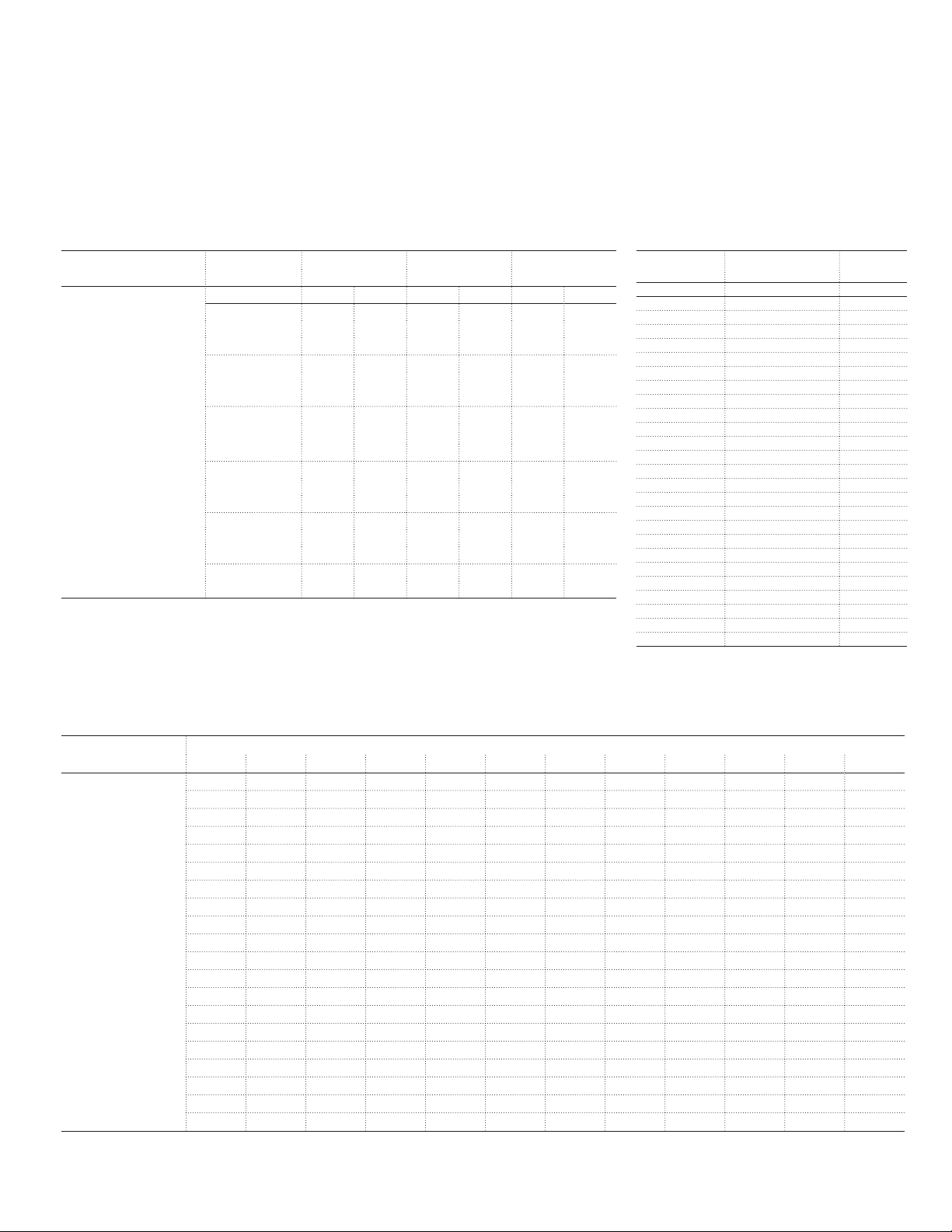
S200, S200P, S200MR, S200MUC—UL 1077, CSA 22.2 No. 235
Technical specifications
S200 S200P S200MR S200MUC
Number of poles 1, 2, 3, 4 1, 2, 3, 4 1, 2, 3, 4 1, 2, 3, 4
Trip curves B, C, D, K, Z B, C, D, K, Z K C, K, Z
Rated current 0.5-63 A 0.2-63 A 0.2-63 A 0.2-63 A
Rated voltage 277/Y480 VAC 277/Y480 VAC 277/Y480 VAC 277/Y480 VAC
60/110 VDC (1/2-pole) 250/500 VDC (1/2-pole)
Short circuit interrupt rating 6 kA 10 kA (up to 25 A) 10 kA 10 kA (DC)
º
Calibration temperature 25
Protection degree IP 20 IP 20 IP 20 IP 20
Mounting position Any Any Any Any
Mounting/installation 35 mm DIN rail 35 mm DIN rail 35 mm DIN rail 35 mm DIN rail
Terminal/cable size AWG 18-4 AWG 18-4 AWG 18-4 AWG 18-4
Service life, mechanical 20,000 operations 20,000 operations 20,000 operations 20,000 operations
Ambient temperature -25
Shock resistance (IEC 60068-2-27) 25 g - 2 shocks - 13 ms 25 g - 2 shocks - 13 ms 25 g - 2 shocks - 13 ms 25 g - 2 shocks - 13 ms
C 25 ºC 25 ºC 25 ºC
º
C to +55 ºC -25 ºC to +55 ºC -25 ºC to +55 ºC -25 ºC to +55 ºC
6 kA (32-63 A) 6 kA (AC)
Auxiliary contact S2C-H6R and signal contact S2C-S6R
Rated current 10
Rated voltage AC/DC 24
Contact 1 pole, single throw
Connection capacity mm
Tightening torque 11 in. lbs (1.2 Nm)
Shock resistance acc. to DIN IEC 68-2-6 5 g, 20 frequency cycles 5...150...5 Hz at 24 VAC/DC, 5 mA auto-reclosing < 10 ms
Mechanical service life 10,000 operations
2
18-14 AWG (0.75...2.5)
Shunt trip
S2C-A1 S2C-A2
Rated voltage AC 12...60 V 110...415 V
DC 12...60 V 110...250 V
Maximum release duration <10 ms <10 ms
Minimum release voltage AC 7 V 55 V
DC 10 V 80 V
Consumption on release AC 40...200 VA 55...210 VA
DC 40...200 VA 55...110 VA
Coil resistance
Terminals 18...6/0.75-16 AWG/mm
Tightening torque 18/2 in. lbs/Nm 18/2 in. lbs/Nm
3.7 V 225 V
2
18...6/0.75-16 AWG/mm
2
Undervoltage release
S2C-UA S2C-UA S2C-UA S2C-UA S2C-UA S2C-UA S2C-UA S2C-UA S2C-UA S2C-UA
12 DC 24 AC 24 DC 48 AC 48 DC 110 AC 110 DC 230 AC 230 DC 400 AC
Standards
Rated voltage AC 24 V 48 V 110 V 230 AC 400 V
DC 12 V 24 V 48 V 110 V 230 V
Frequency 50 ... 60 HZ
Release trip 0.35 UnOVO 0.7 Un V
Terminals 2 x 16/2 x 1.5 AWG/mm
Consumption 0.2 VA 3.6 VA 2 VA 3.6 VA 2.1 VA 3.5 VA 2.2 VA 3.7 VA 2.3 VA 2.4 VA
Resistance to corrosion constant atmosphere: 23/83 – 40/93 – 55/20; variable atmosphere: 25/95 – 40/93
Protection degree IPXXB / IP2X
Tightening torque 3.5/0.4 in. Ibs/Nm
IEC/EN 60947-1110...415 V
2
º
C/RH
38 Miniature Circuit Breakers | US Catalog
Technical specifications
S200, S200P, and S200MR—UL 1077, CSA 22.2 No. 235
Internal resistance and power loss per pole
Internal resistance per pole in mV, power loss per pole in W.
S200 and S200P
Type Rated current Device series Device series Device series
I
n
A mΩ W mΩ W mΩ W
0.5 5500 1.4 6340 1.6 10100 2.5
1 1440 1.4 1550 1.6 2270 2.3
1.6 630 1.6 695 1.8 1100 2.8
2 460 1.8 460 1.9 619 2.5
3 150 1.3 165 1.5 202 1.8
4 110 1.8 120 2.0 149 2.4
6 55 2.0 52 1.9 104 3.7
S200 and S200P
1)
Current intensities 0.5-4 apply exclusively to C-type trip characteristics.
8 15 1.0 38 1.5 53.9 3.45
10 13.3 1.3 12.6 2.0 17.5 1.7
13 13.3 2.3 12.6 1.26 — —
16 7.0 1.8 7.7 2.0 10.9 2.8
20 6.25 2.5 6.7 2.7 6.0 2.4
25 5.0 3.2 4.6 2.9 4.1 2.6
32 3.6 3.7 3.5 3.6 2.8 2.9
40 3.0 4.8 2.8 4.5 2.5 4.1
50 1.3 3.25 1.25 2.9 1.8 4.4
63 1.2 4.8 0.7 5.2 1.3 5.2
B, C, D
1)
K Z
S200MR
Rated current Internal resistance
per pole
A mΩ W
0.2 25300 1.01
0.3 13700 1.23
0.5 4740 1.19
0.75 2067 1.16
1 1270 1.27
1.5 610 1.56
2 442 1.77
3 140 1.26
4 109 1.75
5 50 1.26
6 54 1.94
8 22 1.41
10 18.2 1.82
13 14.8 2.50
15 8.1 1.83
16 11.1 2.83
20 8.5 3.40
25 5.5 3.43
30 3.8 3.39
32 4.6 4.70
35 3.9 4.76
40 2.8 4.40
50 1.7 4.25
60 1.7 6.18
63 1.9 7.56
Power loss
per pole
Temperature derating
Max operating current depending on the ambient temperature of a circuit breaker characteristics type B, C and D
B, C, D, K, and Z Ambient temperatures T (Cº/Fº)
-40/-40 -30/-22 -20/-4 -10/14 0/32 10/50 20/68 30/86 40/104 50/122 60/140 70/158
0.67 0.65 0.62 0.60 0.58 0.55 0.53 0.50 0.47 0.44 0.41 0.37
1.33 1.29 1.25 1.20 1.15 1.11 1.05 1.00 0.94 0.88 0.82 0.75
2.13 2.07 2.00 1.92 1.85 1.77 1.69 1.60 1.51 1.41 1.31 1.19
2.67 2.58 2.49 2.40 2.31 2.21 2.11 2.00 1.89 1.76 1.63 1.49
4.0 3.9 3.7 3.6 3.5 3.3 3.2 3.0 2.8 2.6 2.4 2.2
5.3 5.2 5.0 4.8 4.6 4.4 4.2 4.0 3.8 3.5 3.3 3.0
8.0 7.7 7.5 7.2 6.9 6.6 6.3 6.0 5.7 5.3 4.9 4.5
10.7 10.3 10.0 9.6 9.2 8.8 8.4 8.0 7.5 7.1 6.5 6.0
13.3 12.9 12.5 12.0 11.5 11.1 10.5 10.0 9.4 8.8 8.2 7.5
Amps
17.3 16.8 16.2 15.6 15.0 14.4 13.7 13.0 12.3 11.5 10.6 9.7
21.3 20.7 20.0 19.2 18.5 17.7 16.9 16.0 15.1 14.1 13.1 11.9
26.7 25.8 24.9 24.0 23.1 22.1 21.1 20.0 18.9 17.6 16.3 14.9
33.3 32.3 31.2 30.0 28.9 27.6 26.4 25.0 23.6 22.0 20.4 18.6
42.7 41.3 39.9 38.5 37.0 35.4 33.7 32.0 30.2 28.2 26.1 23.9
53.3 51.6 49.9 48.1 46.2 44.2 42.2 40.0 37.7 35.3 32.7 29.8
66.7 64.5 62.4 60.1 57.7 55.3 52.7 50.0 47.1 44.1 40.8 37.3
84.0 81.3 78.6 75.7 72.7 69.6 66.4 63.0 59.4 55.6 51.4 47.0
112.6 107.2 102.1 97.2 92.6 88.2 84.0 80.0 76.0 72.2 68.6 65.2
140.7 134.0 127.6 121.6 115.8 110.3 1050 100.0 95.0 90.3 85.7 81.5
175.9 167.5 159.5 151.9 114.7 137.8 131.3 125.0 118.8 113.8 107.2 101.8
US Catalog | Miniature Circuit Breakers 39
 Loading...