

Page 1
—
ABB MEASUREMENT & ANALYTICS | OPERATING INSTRUCTION | OI/RS85– EN REV. K
RS85
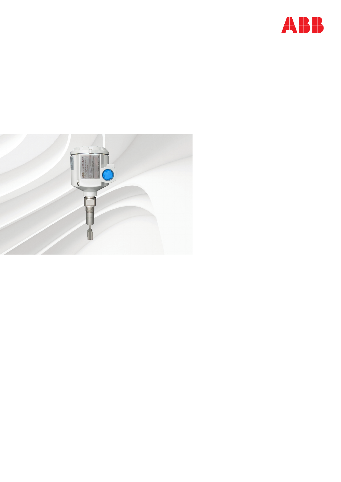
Vibrating fork level switch
K–TEK Level products
Measurement made easy
Introduction
This operating instruction manual provides the
following information:
• installation
• setup
• time delay
• troubleshooting
Page 2

2
RS85 VIBRATING FORK LEVEL SWITCH | OI/RS85-EN REV. K
Contents
1 Description .................................3
2 Installation .................................5
3 Setup . . . . . . . . . . . . . . . . . . . . . . . . . . . . . . . . . . . . . 10
4 Time delay .................................13
5 Troubleshooting........................... 14
6 Warranty statement ........................15
7 ABB RMA form ..............................16
Page 3
RS85 VIBRATING FORK LEVEL SWITCH | OI/RS85-EN REV. K
1 Description
3
Introduction
The RS85 switch is a vibrating fork switch designed for liquid
level detection. The robust sensor design and built–in
temperature compensation ensure reliable response even in
the presence of very extreme process conditions. The LED
indicators of the RS85 modular electronics allow for simple
set–up and status detection. Configuration is via
pushbuttons or a provided magnet. The rugged construction
allows it to withstand the rigors of just about any industrial
environment.
Theory of operation
The RS85 vibrating switch utilizes a piezoelectric driven
tuning fork that exhibits a change in resonant frequency
when the forks are immersed in any liquid. 'Smart'
microprocessor–based electronics keep the sensor in a
resonant state as it changes from dry to wet or wet to dry.
The resonant frequency is continuously monitored for
changes created by a wet or dry sensor and an alarm (change
in LED) is provided along with a DPDT relay. An important
feature of this device is that its resonant frequency is not
significantly affected by coating on the fork unless the space
between the forks is bridged. The RS85 ability to identify true
liquid level in viscous, coating or aerated liquid is
unparalleled. The self–test option continuously checks for
fault conditions such as a damaged sensor and under fault
conditions displays a blinking red LED visible through the
glass cover. Applications include high/low liquid level
detection and are unaffected by parameters such as specific
gravity, dielectric constant or mounting position of the
sensor.
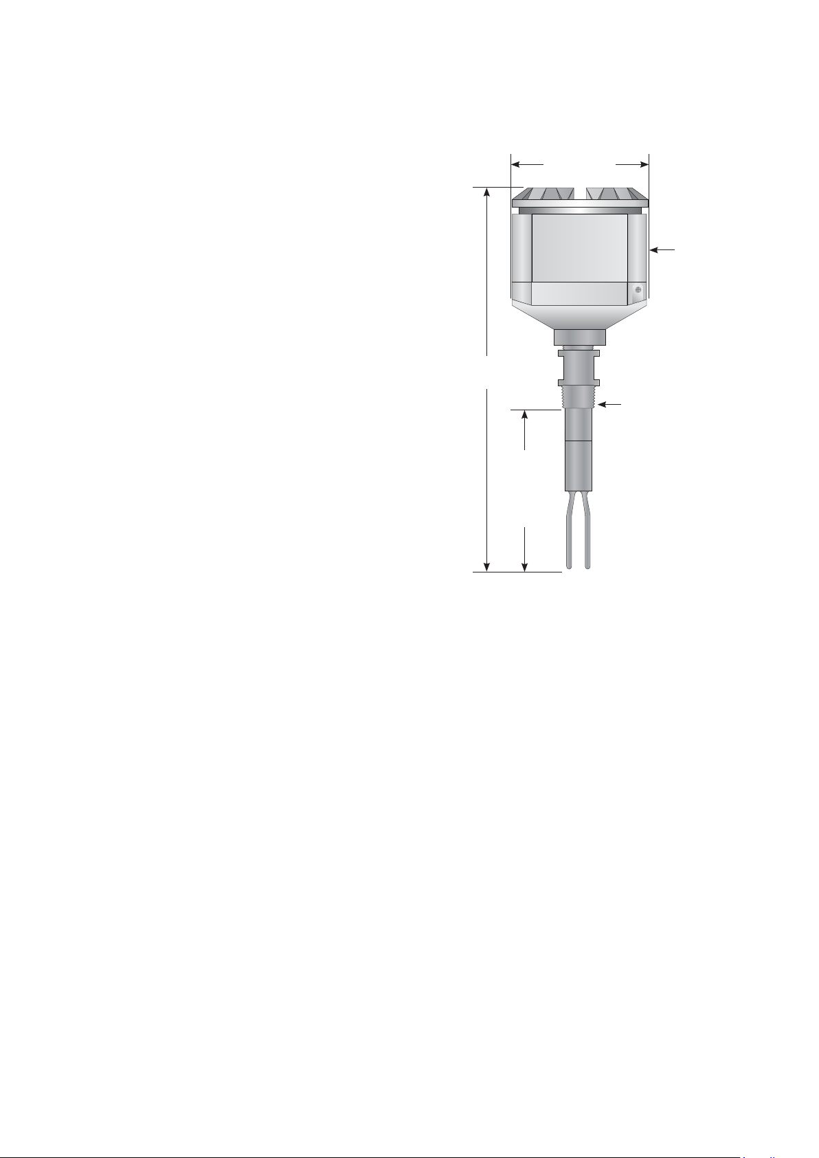
Dimensions
111 mm
19.05 mm (¾ in)
FNPT
cable entry
279 mm (11 in)
Standard
19.05 mm (¾ in)
MNPT standard
Standard
86 mm
PL*
*Trip point 19.05 mm (¾ in)
from end of probe type
Figure 1
Specification
For detailed specifications consult the RS85 data sheet (DS/
RS85–EN).
Page 4
4
RS85 VIBRATING FORK LEVEL SWITCH | OI/RS85-EN REV. K
... 1 Description
Sample applications
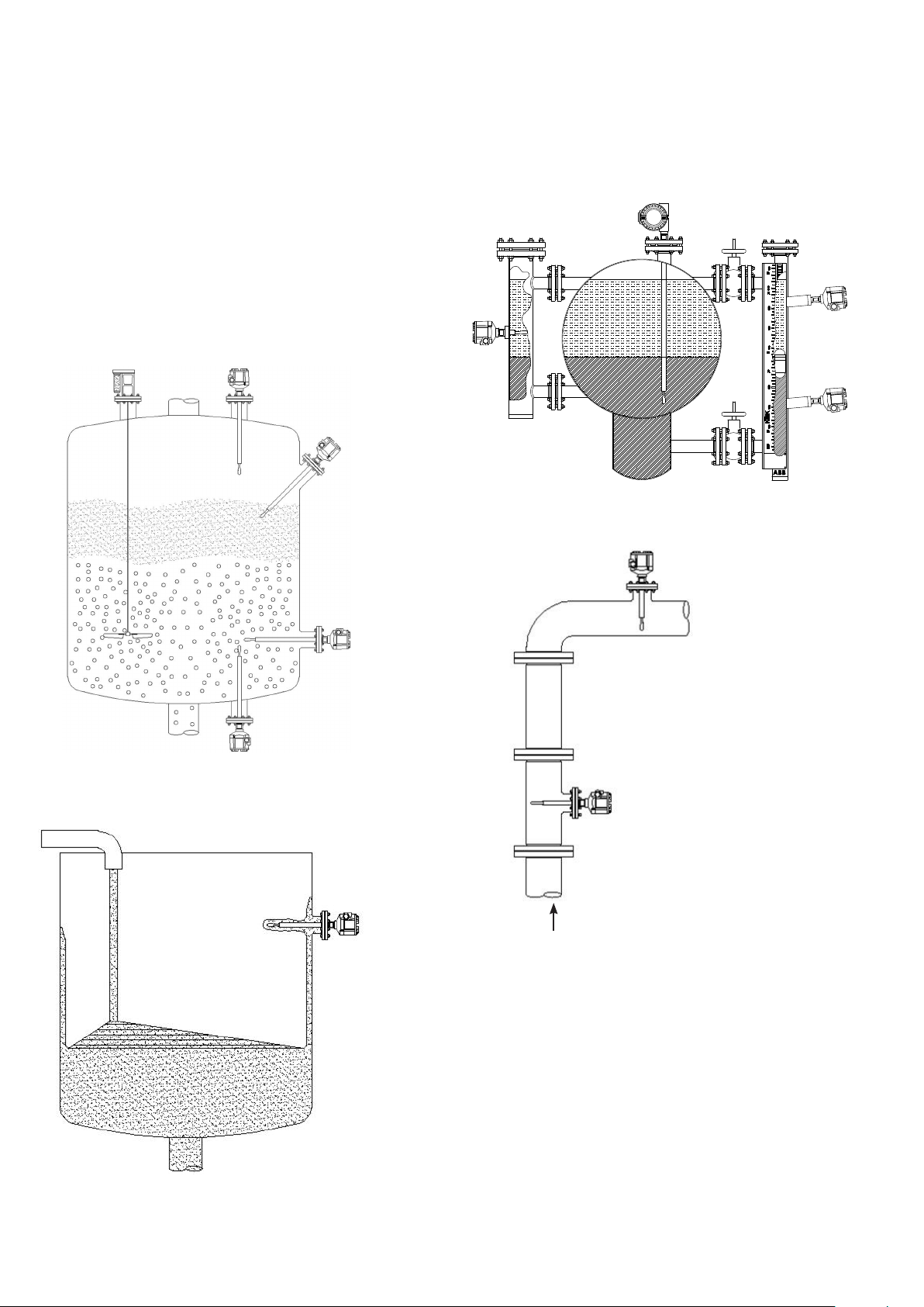
The RS85 can be used for level detection in tanks, vessels or
piping containing all types of hot or cold liquids and is
suitable for high/low level detection applications in
hazardous areas. The RS85 can be mounted in any
orientation. In vertical applications where room allows, the
unit can be extended into the vessel (up to 84 in) with an
extension tube. The RS85 is also available with Teflon
coatings or alloy wetted parts for use in corrosive fluid and
sticky applications.
RS85
switches
mounted in
external
chamber
Figure 4
RS85 dual compartment
housing and custom
insertion length
RS85
switches
mounted in KM26
magnetic level
gauge
.
.
.
.
2
.
.
Figure 2
Figure 3
Empty pipe detection, level in
vertical pipe
(not to be used as a flow
switch) maximum velocity
.5FPS
Figure 5
Page 5
RS85 VIBRATING FORK LEVEL SWITCH | OI/RS85-EN REV. K
2 Installation
Mounting
After unpacking the unit, inspect it for any evidence of
shipping damage. Inspect the fork tines to insure that they
are not bent. Forks should be parallel to each other. Any
claims for damage due to shipping must be filed with the
carrier who handled the package (s).
• Select a mounting location for the switch and the sensor
probe. Your unit may be an integral mounting option or the
remote mounting option. The integral mounting unit
consists of a single enclosure that includes the electronic
module and the sensor probe. The remote mounting unit
consists of two enclosures, one containing the electronic
module and the other containing the sensor probe.
• Be sure that there is sufficient clearance around the
mounting position to allow for the turning radius of the
switch or remote sensor enclosure as the unit is screwed
into place. Allow sufficient room above the vessel entry to
be able to insert the probe into the opening of the vessel.
• The standard size of the threaded vessel coupling is ¾ in
NPT for most probes. Other size threaded connections or
flanges are also available.
• Install and tighten threaded process connection switches
with a spanner wrench on the wrench flats of the threaded
connection.
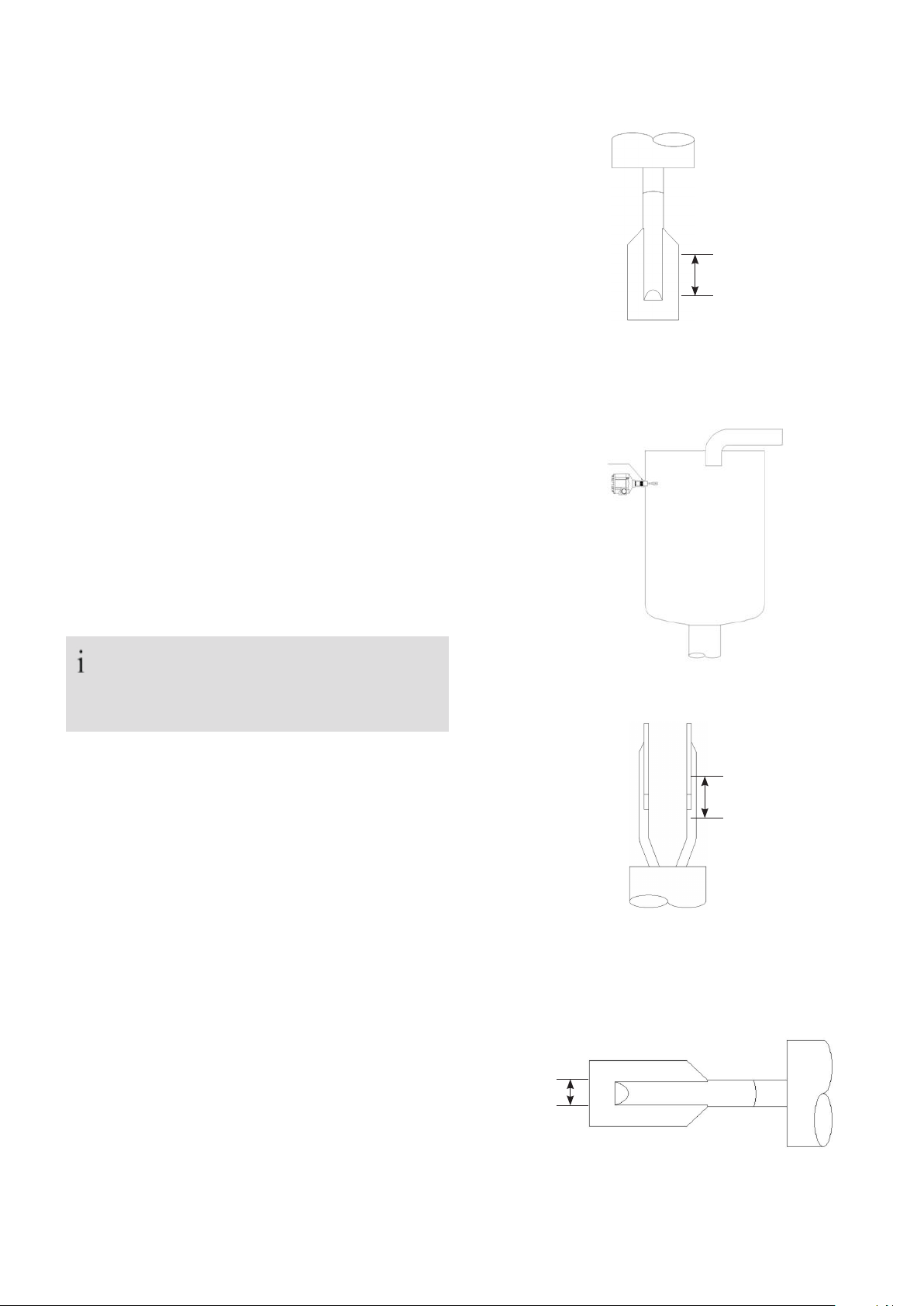
5
Switch point
Top mounted
Figure 6
RS85 mounted via
¾ in NPT
connector
NOTE
Do not rotate switch housing on process connection.
Switch performance may be affected.
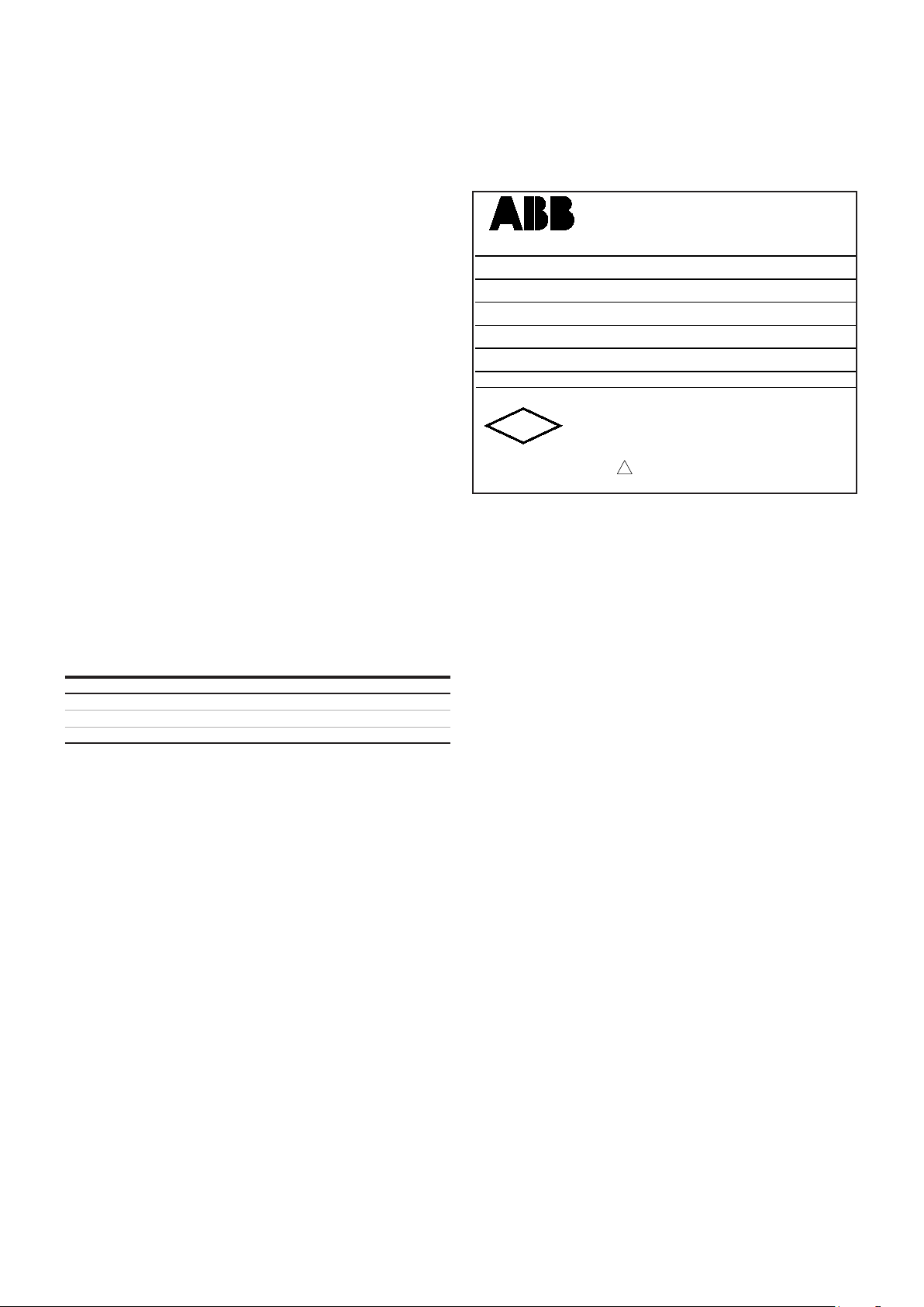
• The information included on the enclosure label should be
visible. If necessary clean the label using a cloth soaked
with either water or isopropyl alcohol.
Tank mounting
The RS85 can be mounted for high or low level detection using
a flange or the standard ¾ in NPT connection.
Switch point and mounting position
Switch points on the sensor depend on the mounting
position. The switch point is determined by the position of
the tuning fork.
Figure 7
Switch point
Bottom mounted
Figure 8
Switch Point
Figure 9
Side mounted
Page 6
6
RS85 VIBRATING FORK LEVEL SWITCH | OI/RS85-EN REV. K
2 ...Installation
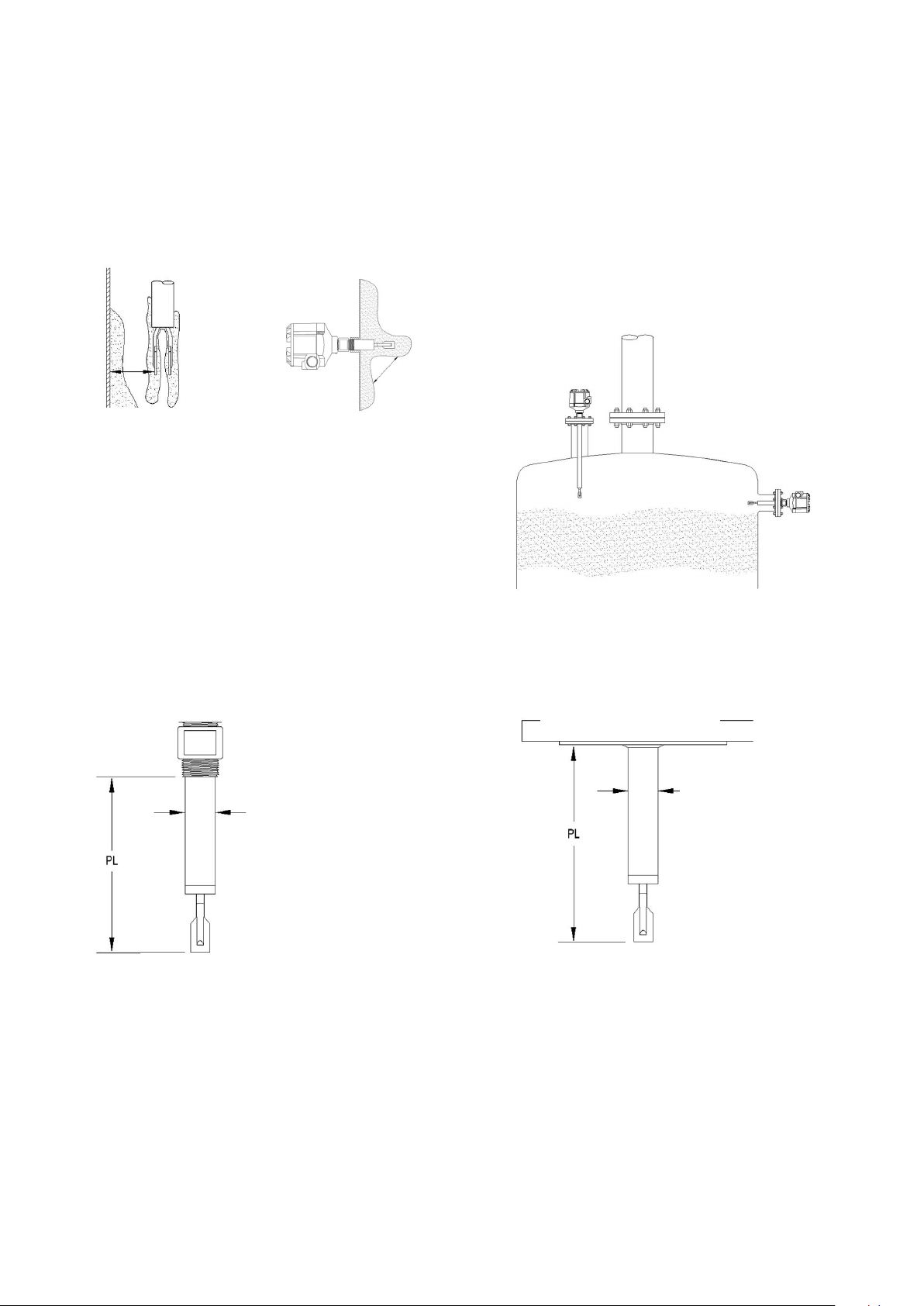
Mounting for vessel wall build–up
If there is a potential for build–up on the vessel wall, mount
the RS85 with sufficient distance between the wall and the
fork assembly to prevent bridging.
*
Vertical top mounted
Figure 10
*Ensure that there is sufficient distance between the build–up
expected on the tank and the forks.
Extended into vessel,
side mounted
*
Extended Probe Lengths (PL)
The sensor length 'PL' for the RS85 will differ based on the
process connection. A threaded sensor PL is measured from
the bottom process thread to the tip of the fork tine. A
flanged sensor PL is measured from the face of the flange to
the tip of the fork tine.
Mounting position with extension tubes
If ordering the RS85 with an extended probe length, ensure
there is adequate space between outside walls or ceilings and
the vessel mounting point
A short extended probe length (up to 20 in) can be mounted
in any orientation. An RS85 with an extended probe length
over 20 in (up to 84 in) must be mounted vertically.
Figure 12
Figure 11
19.05 and 25.4 mm
(¾ In and 1 in)threaded
21.5 mm
(0.8500 in) dia.
From lower edge of thread
Flange connection
21.5 mm
(0.8500 in) dia.
Figure 13
Page 7
RS85 VIBRATING FORK LEVEL SWITCH | OI/RS85-EN REV. K
2 ...Installation
7
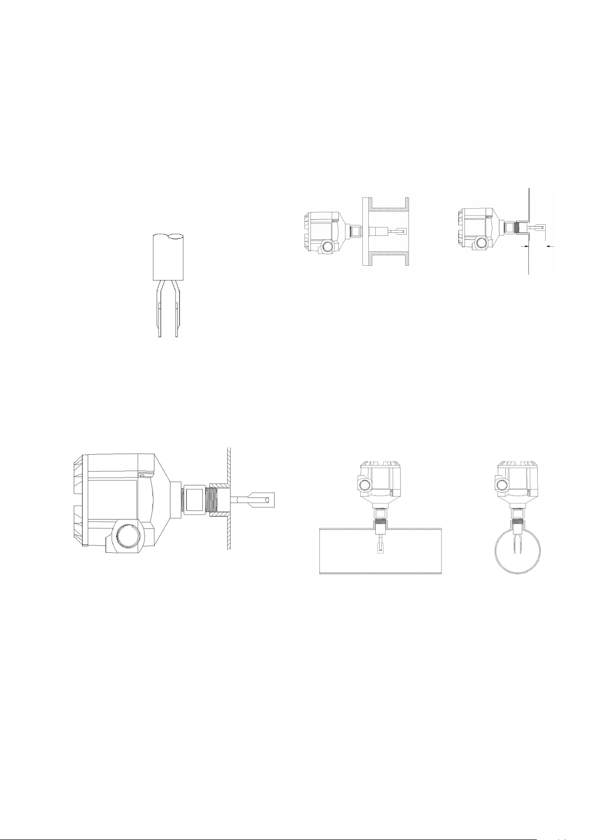
Mounting for high viscosity liquids
High viscosity liquids require proper mounting to ensure
accurate, repeatable service. With high viscosities, the
optimum mounting is vertical from the vessel top or
horizontal (flush mounted from the side).
Note: Horizontal mounting: Position the forks so that the
narrow edge of the tines are vertical. This ensures that the
liquid or gelatinous process can run off easily.
Vertical top mounted
Mounting for low viscosity liquids
Mounting positions for low viscosity liquids are shown below.
If the RS85 fork is nozzle mounted with a flange and does not
extend beyond the wall of the vessel, a minimum nozzle
diameter of 2 in is required. If mounted into a threaded
nozzle, forks should protrude past the wall of the vessel.
Min.
Min. 2 in
(DN50)
* Deburr the nozzle surfaces
Figure 15
1 in
(25)
Pipe mounting and empty pipe detection
The RS85 can be mounted into pipe lines of 2 in and larger
diameters.
Note: To avoid blockage of the flowing material, ensure
narrow edge of forks is parallel with pipe walls.
Figure 14
Flush side mounted
Correct side
mount fork
orientation
To maintain optimum performance in flow or no flow
applications, the liquids should have low viscosities and low
flow velocities. (less than .5 FPS)
Figure 16
Empty pipe detection
Page 8

LED 1 LED 2
S2
RS85
8
RS85 VIBRATING FORK LEVEL SWITCH | OI/RS85-EN REV. K
2 ...Installation
CAUTION
When making the opening in the vessel, observe all
safety requirements of the area in which the work is
being done. Be especially careful when working with
pressure vessels.
The Model RS80/RS85 unit may not work properly if:
• there is a conductive bridge between the paddles of the
fork.
• the fork tines are not in vertical position.
• there is a high turbulence level
• probe is located near a material fill line.
• probe is mounted improperly.
The model RS80/RS85 unit may be damaged if:
• temperature in the housing exceeds appropriate limits.
• the process temperature exceeds probe’s operating
limits.
• the electronic module is subjected to excessive vibration
or shock.
• vessel pressure exceeds process operating pressure
rating of probe.
• probe is located near a material fill line.
If any of the above statements apply to your application, do
not install the switch until you contact your local
representative or the ABB factory for further instructions.
Integral and remote units
Integral units
• Install the switch into the vessel coupling and connect
conduit between the switch and the power supply source
as required.
• Be sure the conduit is suitable for the environment in
which the units are to be used.
Remote units
• Install the remote sensor probe into the vessel coupling.
Select a suitable location for the instrument housing that
allows convenient access for calibration and meets
environmental conditions of the unit.
• Connect conduit between the remote sensor housing and
the instrument housing.
• Connect the RG62 type coaxial cable assembly supplied
with the unit from the remote probe to the instrument
input.
• Connect conduit between the switch and the supply.
source as required (figure 17 and 19). Be sure the conduit
is suitable for the environment in which the units are to
be used.
CAUTION
Due to the extremely wide range of control and/or
alarm applications in which the unit may be used, it
is not possible to show all conceivable wiring
diagrams. Consult your representative or factory if
further assistance is needed.
Caution
Be sure that all wiring and conduit conforms to the
requirements of the National Electrical Code and any
enforcing authorities or agencies having jurisdiction over the
installation. Be sure that any special conditions, such as
hazardous area locations, are given full consideration.
• After installation and wiring, it is necessary to set–up the
unit to the particular vessel and material that will be
measured, using the standard calibration procedure.
• The Resonator Vibrating Switch is designed to monitor
levels of liquid products with a viscosity not greater than
1000 cp.
NOTE
A) All field wiring connected to the RS85 switch must
comply with applicable National Electric Code or
applicable guidelines.
B) Do not use the switch on vessels with operating
temperatures above 200 °F without having the high
temperature option (all Teflon insulation).
C) Any conduit or fittings in close proximity to a
magnetically activated switch should be aluminum or
some other non–magnetic material. This is necessary
to avoid interference with the operation of the
magnetically activated reed switches.
D) Unit is designed for installation in an overvoltage
category 1, pollution degree 2, as outlined by section 6
of the IEC 1010 standard.
E) The maximum altitude of operation is 6560 ft
(2000 m).
F) Protective grounding: The level switch is equipped
with grounding screw locations, both internal and
external of the housing.
LED 1 LED 2
S1
RS85
S2
24VDC
L N
120VAC
+ -
240VAC
Figure 17
C1
C2
NC1
NO1
NC2
NO2
Page 9
RS85 VIBRATING FORK LEVEL SWITCH | OI/RS85-EN REV. K
REV REASON APPROVED DATE
A
ECN0221
E.F.
03/27/06
B
ECN0347
E.F.
12/05/06
C
ECN0348
E.F.
04/04/07
D ECN1053 MS
11/30/16
E
WRM ECR-1145
DWM
04/17/17
F
ECR-1145
DWM
09/11/18
12
3
4
C
D
CAUTION: DO NOT OPEN WHEN EXPLOSIVE ATMOSPHERE IS PRESENT
TAG NO:
MAX TEMP - HOUSING: 158°F; SENSOR:
WORKING / MAX PRESSURE:
MODEL NO:
SERIAL NO:
APPROVED
FM
MADE IN USA WARMINSTER PA 18974 TAG0121
SINGLE SEAL
CL I, DIV 1, GRPS A,B,C,D
CL II, DIV 1, GRPS E,F,G. CL III,
T6 AT 70°C AMBIENT
CONDUIT SEAL NOT REQUIRED
!
SEE MANUALNEMA 4X
K-TEK PRODUCTS
2 ...Installation
9
Installation requirements (Ex d):
The RS85 is intended for mounting in the boundary of a zone
0 and zone 1 hazardous area
When the HT6 – High temperature extension option is used
both the enclosure and the HT6 adapter must be entirely
located in zone 1.
The RS85 must be installed in accordance with an appropriate
code of practice such as EN/ IEC 60079–14.
Flameproof joints are not intended to be repaired.
Cable entry temperatures may reach 80 °C. Use field wires
suitable for this temperature.
Cable or conduit entries must be fitted with a suitably
certified cable entry device with or without the use of a
suitably approved thread adaptor, where conduit is used a
suitably approved stopping box shall be provided
immediately on the entrance of the enclosure.
Unused cable entry holes shall be closed by a suitably
approved Ex d blanking plug.
Markings
K-TEK PRODUCTS
MODEL NO:
SERIAL NO:
TAG NO:
MAX TEMP - HOUSING: 158°F; SENSOR:
WORKING / MAX PRESSURE:
CAUTION: DO NOT OPEN WHEN EXPLOSIVE ATMOSPHERE IS PRESENT
CL I, DIV 1, GRPS A,B,C,D
FM
APPROVED
MADE IN USA WARMINSTER PA 18974 TAG0121
Figure 18
CL II, DIV 1, GRPS E,F,G. CL III,
T6 AT 70°C AMBIENT
CONDUIT SEAL NOT REQUIRED
SEE MANUALNEMA 4X
!
SINGLE SEAL
Temperature classes are based on the following table in
relation to the maximum process temperature:
Table 1
Maximum process temperature Temperature class
Page 10
10
RS85 VIBRATING FORK LEVEL SWITCH | OI/RS85-EN REV. K
3 Setup (Configuring Switch)
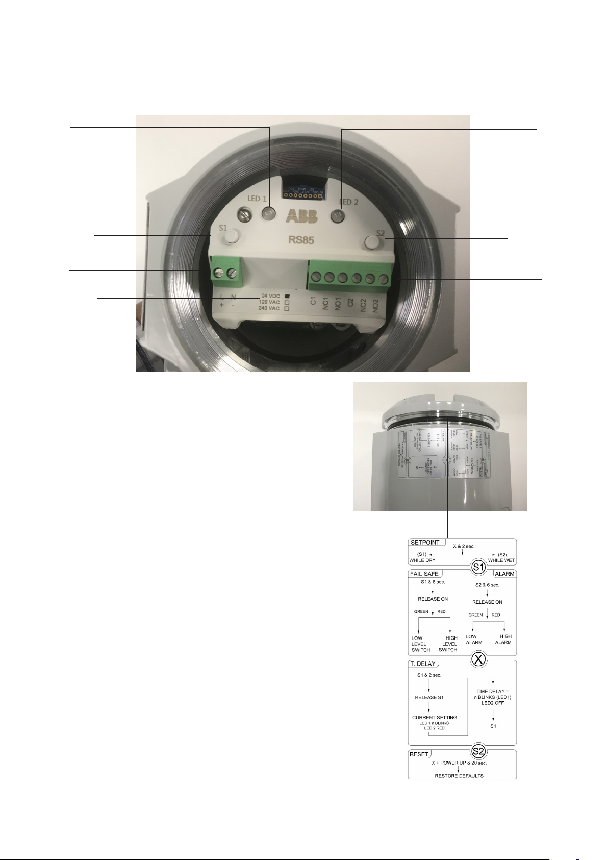
Accessing setup adjustments
LED 1
S1
pushbutton
Power
input
Power
requirement
Figure 19
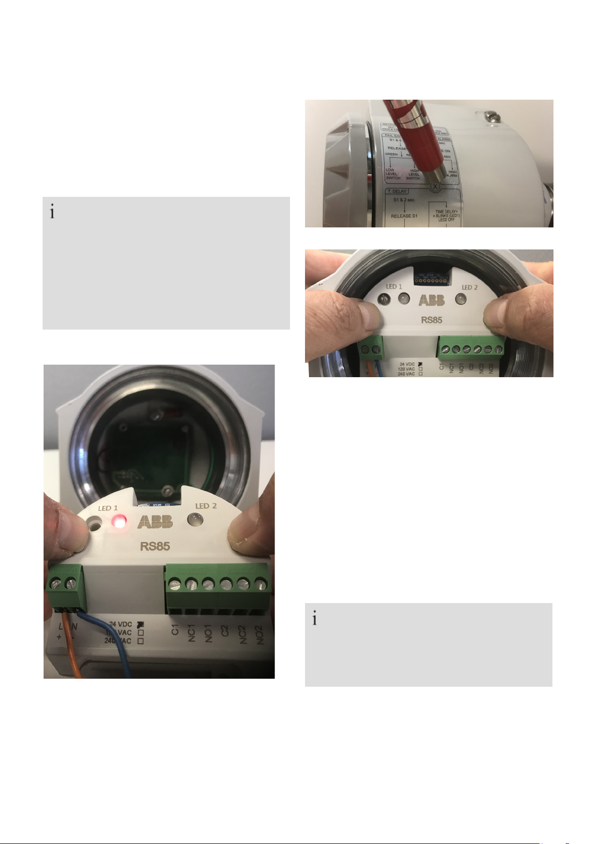
Setup of the RS85 may be achieved using a (1) magnet
(provided with switch) positioned on the housing or (2) by
means of the pushbuttons on the module. In the following
operations, pushbuttons (Figure 19) will correspond to
magnet positions (Figure 20) as follows:
LED 2
S2 pushbutton
Relay
S1 position = S1 button only
S2 position = S2 button only
X position = S1 and S2 simultaneously
During normal operation, LED1 will light either RED or GREEN
based on the settings of the switch.
Initial setup instructions:
Step 1: RS85 (resets to factory defaults)
Power up the electronic module with it disconnected
from the fork assembly (Figure 21). Press S1 and S2
buttons of the electronic module and hold for several
Seconds while a sequence of red and green lights display
ending with LED1 RED (Figure 21). The RS85 electronic
module is now set to factory defaults. Re–install the
electronic module in the fork assembly.
RS85
magnet
position
label
Figure 20
Page 11
RS85 VIBRATING FORK LEVEL SWITCH | OI/RS85-EN REV. K
3 ...Setup (configuring switch)
Factory default settings/reset
Each RS85 will be supplied with the following factory default
settings:
Fail safe mode = high
Time delay = instant
Set points = factory defaults
NOTE
To restore the default settings, always remove the
electronic module from the fork assembly. Then with
power connected to the electronic module Press S1 and
S2 buttons of the electronic module (figure 21) and hold
for several seconds while a sequence of red and green
lights display ending with LED1 RED. Re–install the
electronic module in the fork assembly.
11
Figure 22
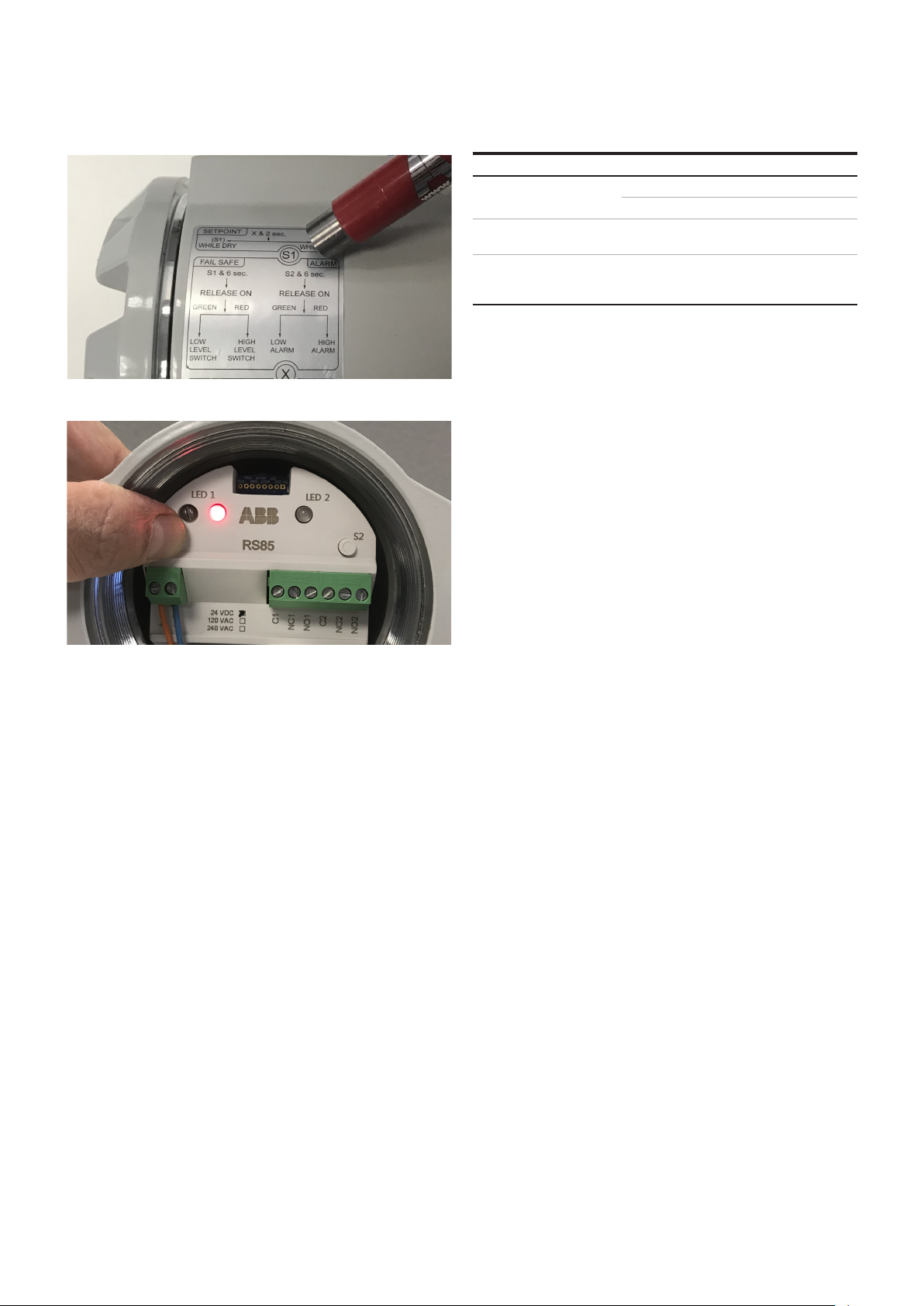
Figure 23
On Initial installation it is recommended that the RS85 be
calibrated to the process conditions/connection. The purpose
is to establish a dry frequency threshold value reference.
Step 2: Calibrating to the process conditions/
connections
With the vibrating fork installed (via. the process
connection) and under dry fork condition power up the
unit. Press S1 and S2 buttons of the electronic module
simultaneously (Figure 23) or hold magnet on ‘X’ of the
magnet position label (Figure 22) for several Seconds. A
sequence of red and green lights will display ending with
LED1 GREEN. The RS85 vibrating fork switch is now
configured to operate under process conditions.
NOTE
The module should be reset to factory defaults (step
1) always before the module is calibrated to process
conditions.
Figure 21
Page 12
12
RS85 VIBRATING FORK LEVEL SWITCH | OI/RS85-EN REV. K
3 ...Setup (configuring switch)
Figure 24
Table 2 – Fail safe/relay operation
Fail safe
Low level switch (fail safe
low)
High level switch (fail safe
high)
Default setting
Relay state (led)
Dry fork Wet fork
Off (red)
On (green) Off (red)
On (green)
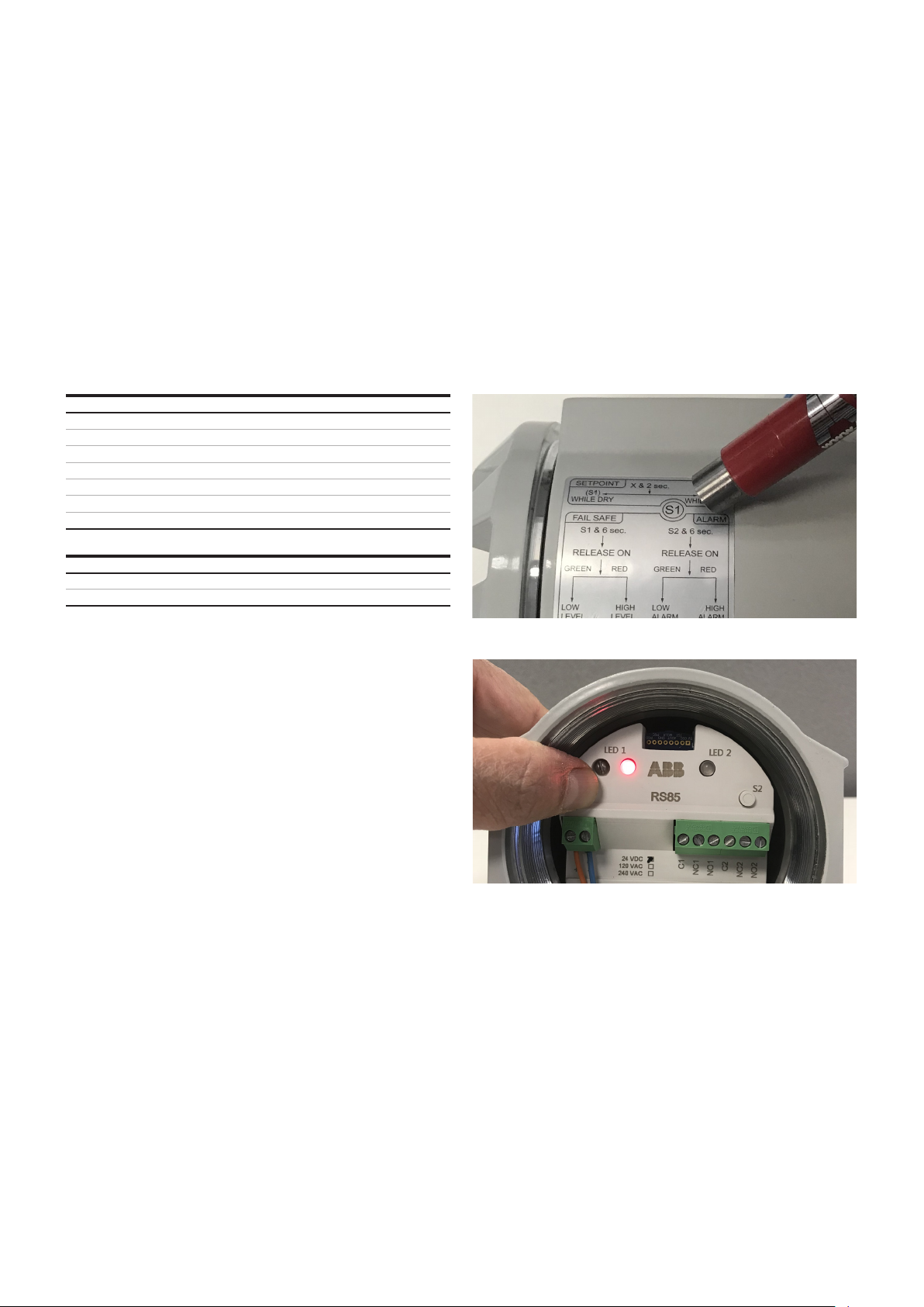
Figure 25
Fail safe/relay operation
A fail safe relay operation is used to energize the relay when
the switch is in normal condition. This will indicate that the
switch has power. Therefore in a fail safe high application, the
relays will be energized when the level is below the switch (dry
fork) and de–energized when the level is above the switch
(wet fork). Likewise, setting the switch Fail Safe to Low will
cause the relays to be energized when the level is above the
switch (wet fork) and de–energize when the level is below
switch (dry fork). The default setting for the fail safe or relay
operation of the resonator is high. To change the fail safe
operation for the relays, place the magnet in the S1 position
(Figure 24) or press pushbutton S1 (Figure 25) for 5 seconds.
LED1 will change back and forth from red to green. Removing
magnet on red will change fail safe to green (fail safe high).
Removing magnet on green will change fail safe to red (fail
safe low). Should power be lost, the relay will de–energize.
Page 13
RS85 VIBRATING FORK LEVEL SWITCH | OI/RS85-EN REV. K
4 Time delay
13
The RS85 time delay option allows changing the time
response of the relay output, which is very useful in
applications with severe turbulence or agitation.
In typical applications, the RS85 in default settings will
activate the relays instantaneously when the switch point has
been reached. In certain applications it may be necessary to
delay the action of the relays in the switch. If this is desired, a
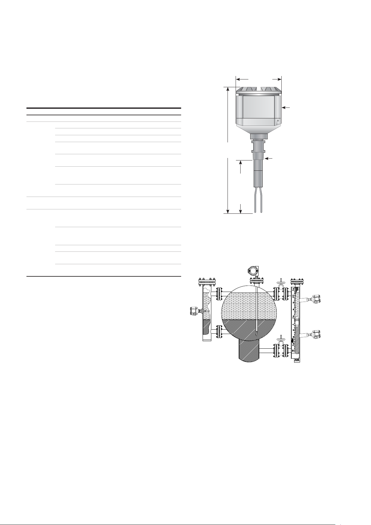
time delay for the relays can be set. To enter the time delay
setup mode, place the magnet on 'S1' (figure 26) or press
pushbutton S1 (figure 27) for more than 1 second but less
than 6 seconds. The following sequence of LED’s will be
observed:
Table 3 – Time delay adjustment
OPERATION LED 1 LED 2
Normal Green or red Off
Off Off
Displaying current time delay 'Green' Red
Off Off
S1 PER table 4 'Green' Off
'_' – indicates a blinking LED
Table 4 – Time delay setting
Seconds
After LED2 turns 'off', LED1 will blink in correspondence to the
different time delay settings per table 4. When the desired
time delay is reached, place the magnet on the 'S1' position
(see figure 26). The time delay will be set and the RS85 will
return to normal operation. If a time delay is not selected, the
RS85 will return to its current operating mode without
changing the current time delay setting. During normal
operation of the switch, if a time delay is selected, LED1 will
change color when the switch point has been reached. The
relays will respond after the elapsed time delay on both
energized and de–energized actions.
While LED2 is lit RED, LED1 will blink the current time delay
setting per table 4.
Figure 26
Figure 27
Page 14
14
RS85 VIBRATING FORK LEVEL SWITCH | OI/RS85-EN REV. K
5 Troubleshooting
Fault mode
If a fault is detected, either electrical or mechanical, LED 2 will
blink in RED and the normal ON relay is de–energized. This
LED is integral to the modular electronics and can only be
seen through the glass viewing cover.
Table 5 – Fault mode
Fault Reason Remedy
No Power Check power
Faulty wiring Check wiring
Faulty electronic Module Replace module
Confirm that density is above
.5 SG
Clean fork
Exchange fork and
process connection (requires
sending to factory)
Replace module; put fuse in
contact circuit
Set correct mode at electronic
module
Recalibrate switch in process
connection
Set time delay
Remove water, screw cover and
cable gland tight
Does not
switch
Switches
incorrectly
Sporadic
faulty
switching
Density of liquid too low
Fork encrusted with too
much buildup
Fork corroded or bent
Contacts welded together
(after short–circuit)
Fail–safe mode
set wrong
Relay switches on & off
while in dry fork conditions
Thick heavy foam, very
turbulent conditions,
foaming liquid
Extreme RFI Use shielded cable
Water in housing
Output overloaded Reduce load: (cable) capacitance
Standard single compartment dimensions
111 mm
19.05 mm (¾ in)
FNPT conduit
279 mm (11 in)
standard
19 mm (¾ in)
MNPT
standard
Standard
86 mm
PL*
Figure 28
Resonator sample applications
RS85 dual
RS85
switches
mounted
in external
chamber
compartment
housing and custom
insertion length
RS85
switches
mounted in
KM26 magnetic
level gauge
Figure 29
.
.
.
.
2
.
.
Page 15

RS85 VIBRATING FORK LEVEL SWITCH | OI/RS85-EN REV. K
6 Warranty statement
15
5 YEAR WARRANTY FOR:
KM26 Magnetic Liquid Level Gauges; MagWave Dual Chamber
System; LS Series Mechanical Level Switches (LS500, LS550,
LS600, LS700, LS800 & LS900) (does NOT include switching
mechanisms, ie. MS30, MS40, MS41, PS35 & PS45); EC External
Chambers, STW Stilling Wells and ST95 Seal Pots.
2 YEAR WARRANTY FOR:
AT100, AT100S and AT200 series transmitters; RS85 liquid
vibrating fork switches; TX & TS, thermal dispersion switches;
IR10 and PP10 External Relays; MT2000, MT5000, MT5100 and
MT5200 radar level transmitters; RI100 Repeat Indicators; KP
paddle switches; A02 & A75 RF capacitance level switches;
Buoyancy Level Switches (MS50, MS10, MS8D & MS8F);
Magnetic Level Switches (MS30, MS40, MS41, PS35, PS45 and
LMS100).
1 YEAR WARRANTY FOR:
AT500 and AT600 series transmitters; LaserMeter and
SureShot series laser transmitters; LPM200 digital indicator;
DPM100 digital indicators; APM100 analog indicators; KVIEW
series digital indicators and controllers; GRANUPOINT and
SLUDGEPOINT vibrating fork switches, SOLITRAK Electro–
Mechanical Continuous Measuring Devices, KSONIK ultrasonic
level switches, transmitters & transducers, ChuteMaster
Microwave Transmitter / Receiver and TiltMaster Switches.
SPECIAL WARRANTY CONSIDERATIONS:
ABB Inc, K–TEK Products, does not honor OEM warranties for
items not manufactured by ABB Inc, K–TEK Products, (i.e.
Palm Pilots). These claims should be handled directly with the
OEM.
ABB Inc, K–TEK Products, will repair or replace, at ABB Inc, K–
TEK Product’s, election, defective items which are returned to
ABB Inc, K–TEK Products, by the original purchaser within the
period specified above from the shipment date of the item
and which is found, upon examination by ABB Inc, K–TEK
Products, to its satisfaction, to contain defects in materials
or workmanship which arose only under normal use and
service and which were not the result of either alterations,
misuse, abuse, improper or inadequate adjustments,
applications or servicing of the product. ABB Inc, K–TEK
Products’s, warranty does not cover the repair or replacement
of units that fail from the effects of excessive vibration unless
the units are originally designed for vibration application. In
addition, ABB Inc, K–TEK Products’s warranty does not
include on–site repair or services. Field service rates can be
supplied on request.
If a product is believed to be defective, the original purchaser
shall notify ABB Inc, K–TEK Products, and request a Returned
Material Authorization before returning the material to ABB
Inc, K–TEK Products, with transportation prepaid by the
purchaser. (To expedite all returns/repairs from outside of
the United States, consult ABB Inc, K–TEK Product’s customer
service team ([email protected]) to determine an
optimal solution for shipping method and turnaround time.)
The product, with repaired or replaced parts, shall be
returned to the purchaser at any point in the world with
transportation prepaid by ABB Inc, K–TEK Products, for best–
way transportation only. ABB Inc, K–TEK Products, is not
responsible for expedited shipping charges. If the product is
shipped to ABB Inc, K–TEK Products, freight collect, then it
will be returned to the customer freight collect.
If inspection by ABB Inc, K–TEK Products, does not disclose
any defects in material or workmanship, ABB Inc, K–TEK
Product’s, normal charges for repair and shipment shall apply
(minimum 250.00 USD).
The materials of construction for all ABB Inc, K–TEK products,
are clearly specified and it is the responsibility of the
purchaser to determine the compatibility of the materials for
the application.
THE FOREGOING WARRANTY IS ABB INC, K–TEK PRODUCT’S,
SOLE WARRANTY AND ALL OTHER WARRANTIES EXPRESSED,
IMPLIED, OR STATUTORY, INCLUDING ANY IMPLIED
WARRANTY OF MERCHANTABILITY OF FITNESS FOR A
PARTICULAR PURPOSE, ARE EXCLUDED AND NEGATED TO
THE MAXIMUM EXTENT PERMITTED BY LAW. NO PERSON OR
REPRESENTATIVE IS AUTHORIZED TO EXTEND ANY OTHER
WARRANTY OR CREATE FOR ABB INC, K–TEK PRODUCTS, ANY
OTHER LIABILITY IN CONNECTION WITH THE SALE OF ABB
INC, K–TEK’S PRODUCTS. THE REMEDIES SET FORTH IN THIS
WARRANTY ARE EXCLUSIVE OF ALL OTHER REMEDIES
AGAINST ABB INC, K–TEK PRODUCTS. ABB INC, K–TEK
PRODUCTS, SHALL NOT BE LIABLE FOR ANY
CONSEQUENTIAL, INCIDENTAL, OR SPECIAL DAMAGES OF
ANY KIND. ABB INC, K–TEK PRODUCT’S, SOLE OBLIGATION
SHALL BE TO REPAIR OR REPLACE PARTS (FOUND TO BE
DEFECTIVE IN MATERIALS OR WORKMANSHIP) WHICH ARE
RETURNED BY THE PURCHASER TO ABB INC, K–TEK
PRODUCTS.
Page 16
16
7 ABB RMA Form
RS85 VIBRATING FORK LEVEL SWITCH | OI/RS85-EN REV. K
ABB Inc.
K–TEK Products
125 E. County Line Road
Warminster PA 18974–4995, USA
Tel: +1 215 674 6000
Fax: +1 215 674 7183
Email: ktek–[email protected]
*** IMPORTANT CUSTOMER NOTICE: PLEASE READ PRIOR TO RETURNING PRODUCTS TO ABB***
Be sure to include the Return Authorization (RA) number on the shipping label or package to the attention: Customer Service. A copy of this document should also be included with the packing list. ABB wants to maintain a safe work environment
for its employees. In the event, the returned product or material has been in contact with a potentially hazardous chemical,
per federal regulations, the customer must provide evidence of decontamination and the related chemical composition
and characteristics. In order to expedite your return, please include the applicable Material Safety Data Sheets (MSDS) and
decontamination tags by affixing these documents in close proximity to the shipment label for identification purposes.
Return Authorization Form
Customer: Date:
Contact Name: Product:
Contact Email: Serial No:
Contact Phone: Job No:
Contact Fax: Service Rep:
Completed by Customer
Reason
Problem Found: None
Action: None
Requested:
Is expedited return shipping requested? Yes
If yes, please provide a purchase order or your shipper’s account number (ex. FedEx or UPS). ABB pays return transport
via standard ground shipments only.
If purchase order is issued, a copy of purchase order must be included with return documentation.
Is ABB authorized to repair items determined to be non-warranty? Ye s
If yes, a copy of purchase order must be included with return documentation.
Account #:
Customer PO:
Has product been in contact with any potentially hazardous chemical? Yes
If yes, documentation product and forward MSDS to ABB, “ATTN: Customer Service”
Date:
Return Repaired Product to Address
Shipping Address: Billing Address:
Ship Via:
Page 17

Notes
RS85 VIBRATING FORK LEVEL SWITCH | OI/RS85-EN REV. K
17
Page 18

18
Notes
RS85 VIBRATING FORK LEVEL SWITCH | OI/RS85-EN REV. K
Page 19

Notes
RS85 VIBRATING FORK LEVEL SWITCH | OI/RS85-EN REV. K
19
Page 20

—
ABB Inc.
Measurement & Analytics
125 E. County Line Road
Warminster PA 18974–4995, USA
Tel: +1 215 674 6000
Fax: +1 215 674 7183
ABB Inc.
8940 Bluebonnet Blvd. – Suite 100
Baton Rouge, LA 70810 USA
Tel: +1–225–408–0800
abb.com/measurement
We reserve the right to make technical changes or modify the contents of this document without
prior notice. With regard to purchase orders, the agreed particulars shall prevail.
ABB does not accept any responsibility whatsoever for potential errors or possible lack
of information in this document.
We reserve all rights in this document and in the subject matter and illustrations contained therein.
Any reproduction, disclosure to third parties or utilization of its contents – in whole
or in parts – is forbidden without prior written consent of ABB.
© 2018 ABB
OI_RS85–EN_Rev. K_ 11. 2018
 Loading...