

Page 1

—
RELION® PROTECTION AND CONTROL
611 series
Operation Manual
Page 2

Page 3
Document ID: 1MRS757453
Issued: 2019-04-10
Revision: C
Product version: 2.0
© Copyright 2019 ABB. All rights reserved
Page 4

Copyright
This document and parts thereof must not be reproduced or copied without written
permission from ABB, and the contents thereof must not be imparted to a third party,
nor used for any unauthorized purpose.
The software or hardware described in this document is furnished under a license and
may be used, copied, or disclosed only in accordance with the terms of such license.
Trademarks
ABB and Relion are registered trademarks of the ABB Group. All other brand or
product names mentioned in this document may be trademarks or registered
trademarks of their respective holders.
Warranty
Please inquire about the terms of warranty from your nearest ABB representative.
www.abb.com/relion
Page 5

Disclaimer
The data, examples and diagrams in this manual are included solely for the concept or
product description and are not to be deemed as a statement of guaranteed properties.
All persons responsible for applying the equipment addressed in this manual must
satisfy themselves that each intended application is suitable and acceptable, including
that any applicable safety or other operational requirements are complied with. In
particular, any risks in applications where a system failure and/or product failure
would create a risk for harm to property or persons (including but not limited to
personal injuries or death) shall be the sole responsibility of the person or entity
applying the equipment, and those so responsible are hereby requested to ensure that
all measures are taken to exclude or mitigate such risks.
This product has been designed to be connected and communicate data and
information via a network interface which should be connected to a secure network.
It is the sole responsibility of the person or entity responsible for network
administration to ensure a secure connection to the network and to take the necessary
measures (such as, but not limited to, installation of firewalls, application of
authentication measures, encryption of data, installation of anti virus programs, etc.)
to protect the product and the network, its system and interface included, against any
kind of security breaches, unauthorized access, interference, intrusion, leakage and/or
theft of data or information. ABB is not liable for any such damages and/or losses.
This document has been carefully checked by ABB but deviations cannot be
completely ruled out. In case any errors are detected, the reader is kindly requested to
notify the manufacturer. Other than under explicit contractual commitments, in no
event shall ABB be responsible or liable for any loss or damage resulting from the use
of this manual or the application of the equipment.
Page 6

Conformity
This product complies with the directive of the Council of the European Communities
on the approximation of the laws of the Member States relating to electromagnetic
compatibility (EMC Directive 2014/30/EU) and concerning electrical equipment for
use within specified voltage limits (Low-voltage directive 2014/35/EU). This
conformity is the result of tests conducted by ABB in accordance with the product
standard EN 60255-26 for the EMC directive, and with the product standards EN
60255-1 and EN 60255-27 for the low voltage directive. The product is designed in
accordance with the international standards of the IEC 60255 series.
Page 7
Safety information
Dangerous voltages can occur on the connectors, even though the
auxiliary voltage has been disconnected.
Non-observance can result in death, personal injury or substantial
property damage.
Only a competent electrician is allowed to carry out the electrical
installation.
National and local electrical safety regulations must always be
followed.
The frame of the protection relay has to be carefully earthed.
When the plug-in unit has been detached from the case, do not touch
the inside of the case. The relay case internals may contain high
voltage potential and touching these may cause personal injury.
The protection relay contains components which are sensitive to
electrostatic discharge. Unnecessary touching of electronic
components must therefore be avoided.
Whenever changes are made in the protection relay, measures should
be taken to avoid inadvertent tripping.
Page 8

Page 9

Table of contents
Table of contents
Section 1 Introduction.......................................................................7
This manual........................................................................................ 7
Intended audience.............................................................................. 7
Product documentation.......................................................................8
Product documentation set............................................................8
Document revision history............................................................. 8
Related documentation..................................................................9
Symbols and conventions...................................................................9
Symbols.........................................................................................9
Document conventions.................................................................. 9
Functions, codes and symbols.................................................... 10
Section 2 Environmental aspects...................................................15
Sustainable development................................................................. 15
Disposal of a protection relay........................................................... 15
Section 3 611 series overview........................................................17
Overview...........................................................................................17
Local HMI......................................................................................... 17
Display.........................................................................................18
LEDs............................................................................................19
Keypad........................................................................................ 20
Local HMI functionality................................................................ 22
Protection and alarm indication.............................................. 22
Parameter management ........................................................23
Front communication..............................................................24
Web HMI...........................................................................................24
Command buttons....................................................................... 26
Authorization.....................................................................................27
Audit trail......................................................................................28
Communication.................................................................................30
Self-healing Ethernet ring............................................................ 30
Ethernet redundancy................................................................... 31
Secure communication................................................................ 33
PCM600 tool.....................................................................................34
Connectivity packages.................................................................34
PCM600 and relay connectivity package version........................34
Section 4 Using the HMI.................................................................37
Using the local HMI.......................................................................... 37
611 series 1
Operation Manual
Page 10

Table of contents
Logging in....................................................................................37
Logging out..................................................................................38
Turning the display backlight on.................................................. 38
Selecting local or remote use...................................................... 39
Identifying the device...................................................................39
Identifying relay's IEC 61850 version..................................... 40
Adjusting the display contrast......................................................40
Changing the local HMI language............................................... 41
Changing display symbols...........................................................41
Changing setting visibility............................................................ 41
Navigating in the menu................................................................42
Menu structure....................................................................... 42
Scrolling the display............................................................... 43
Changing the default view...................................................... 43
Browsing setting values...............................................................43
Editing values.............................................................................. 44
Editing numerical values........................................................ 44
Editing string values............................................................... 46
Editing enumerated values.....................................................46
Committing settings..................................................................... 46
Clearing and acknowledging....................................................... 47
Using the local HMI help..............................................................48
Using the Web HMI.......................................................................... 48
Logging in....................................................................................48
Logging out..................................................................................49
Identifying device.........................................................................49
Navigating in menus.................................................................... 50
Menu structure....................................................................... 51
Showing parameters....................................................................52
Editing values.............................................................................. 55
Committing settings..................................................................... 58
Clearing and acknowledging....................................................... 60
Selecting programmable LEDs view............................................61
Selecting event view....................................................................62
Selecting disturbance records view............................................. 64
Saving disturbance records....................................................64
Triggering disturbance recorder manually..............................65
Deleting disturbance records..................................................66
Selecting phasor diagrams.......................................................... 66
Selecting fault records................................................................. 69
Selecting signal configuration......................................................71
Import and export of settings....................................................... 76
Exporting settings ..................................................................76
2 611 series
Operation Manual
Page 11

Table of contents
Importing settings .................................................................. 77
Exporting report summary........................................................... 79
Using Web HMI help....................................................................80
Section 5 IED operation ................................................................ 83
Normal operation.............................................................................. 83
Disturbance identification................................................................. 83
Disturbance recording triggering................................................. 84
Disturbance record analysis........................................................ 84
Disturbance reports..................................................................... 84
Relay self-supervision................................................................. 84
Relay parametrization.......................................................................85
Settings for relay functionality......................................................85
Settings for different operating conditions................................... 85
Section 6 Operating procedures.....................................................87
Monitoring.........................................................................................87
Indications................................................................................... 87
Monitoring indication messages............................................. 87
Monitoring an internal relay fault ........................................... 87
Monitoring condition monitoring data..................................... 88
Measured and calculated values................................................. 88
Measured values.................................................................... 88
Using the local HMI for monitoring......................................... 89
Recorded data............................................................................. 89
Creating disturbance recordings............................................ 89
Monitoring disturbance recorder data.....................................90
Controlling and reading of disturbance recorder data............ 90
Monitoring fault records..........................................................91
Monitoring events................................................................... 91
Remote monitoring...................................................................... 92
Monitoring protection relays remotely.................................... 92
Controlling........................................................................................ 92
Controlling via the control menu.................................................. 92
Controlling with the closing delay................................................ 93
Resetting IED................................................................................... 94
Clearing and acknowledging via the local HMI............................94
Changing the IED functionality......................................................... 95
Defining the setting group............................................................95
Activating a setting group....................................................... 95
Copying a setting group......................................................... 96
Browsing and editing setting group values.............................96
Activating programmable LEDs................................................... 97
Setting autoscroll delay............................................................... 98
611 series 3
Operation Manual
Page 12

Table of contents
Section 7 Troubleshooting .............................................................99
Fault tracing......................................................................................99
Identifying hardware errors..........................................................99
Identifying runtime errors.............................................................99
Identifying communication errors.................................................99
Checking front communication link operation.........................99
Checking time synchronization.............................................100
Running the display test............................................................ 100
Indication messages.......................................................................100
Internal faults.............................................................................100
Warnings................................................................................... 102
Correction procedures.................................................................... 103
Rebooting the software..............................................................103
Restoring factory settings.......................................................... 103
Setting passwords..................................................................... 104
Identifying relay application problems....................................... 104
Inspecting wiring...................................................................105
Sample data interruptions.................................................... 105
Section 8 Commissioning.............................................................107
Commissioning checklist................................................................ 107
Checking the installation.................................................................107
Checking of the power supply................................................... 107
Checking CT circuits..................................................................108
Checking VT circuits..................................................................108
Checking binary input and output circuits..................................109
Checking binary input circuits...............................................109
Checking binary output circuits............................................ 109
Authorizations.................................................................................110
User authorization..................................................................... 110
Setting IED and communication..................................................... 111
Setting the communication between protection relays and
PCM600.....................................................................................111
Communication link options between PCM600 and
protection relays................................................................... 111
Communication settings............................................................ 112
Serial communication ports and drivers............................... 113
Serial link diagnostics and monitoring.................................. 114
Defining Ethernet port settings............................................. 116
Defining serial port settings.................................................. 116
Setting communication protocol parameters........................ 117
Connecting jumper connectors.............................................117
Setting the local HMI................................................................. 117
4 611 series
Operation Manual
Page 13

Table of contents
Changing the local HMI language........................................ 117
Adjusting the display contrast...............................................117
Changing display symbols....................................................118
Changing the default view.................................................... 118
Setting the system time and time synchronization............... 118
Setting IED parameters............................................................. 120
Defining setting groups.........................................................120
Relay parametrization.......................................................... 122
Defining disturbance recorder channel settings................... 123
Configuring analog inputs.....................................................123
Testing protection relay operation.................................................. 123
Selecting the IED test mode...................................................... 123
Testing the digital I/O interface..................................................124
Testing functions....................................................................... 124
Selecting the internal fault test.................................................. 125
Selecting the IED blocked or IED test and blocked mode......... 125
ABB Product Data Registration...................................................... 126
Section 9 Glossary....................................................................... 127
611 series 5
Operation Manual
Page 14

6
Page 15

1MRS757453 C Section 1
Introduction
Section 1 Introduction
1.1 This manual
The operation manual contains instructions on how to operate the protection relay
once it has been commissioned. The manual provides instructions for monitoring,
controlling and setting the relay. The manual also describes how to identify
disturbances and how to view calculated and measured power grid data to determine
the cause of a fault.
1.2 Intended audience
This manual addresses the operator, who operates the protection relay on a daily basis.
The operator must be trained in and have a basic knowledge of how to operate
protection equipment. The manual contains terms and expressions commonly used to
describe this kind of equipment.
611 series 7
Operation Manual
Page 16

Planning &
purchase
Engineering
Installation
Commissioning
Operation
Maintenance
Decommissioning,
deinstallation & disposal
Quick start guide
Quick installation guide
Brochure
Product guide
Operation manual
Installation manual
Connection diagram
Engineering manual
Technical manual
Application manual
Communication protocol manual
IEC 61850 engineering guide
Point list manual
Cyber security deployment guideline
Section 1 1MRS757453 C
Introduction
1.3 Product documentation
1.3.1 Product documentation set
1.3.2 Document revision history
8 611 series
GUID-0777AFDA-CADF-4AA9-946E-F6A856BDF75E V1 EN
Figure 1: The intended use of manuals in different lifecycles
Product series- and product-specific manuals can be downloaded
from the ABB Web site http://www.abb.com/relion.
Document revision/date
A/2011-11-18 1.0 First release
B/2016-02-22 2.0 Content updated to correspond to the
C/2019-04-10 2.0 Content updated
Product series version History
product series version
Download the latest documents from the ABB Web site
http://www.abb.com/substationautomation.
Operation Manual
Page 17
1MRS757453 C Section 1
Introduction
1.3.3 Related documentation
Product series- and product-specific manuals can be downloaded from the ABB Web
http://www.abb.com/substationautomation.
site
1.4 Symbols and conventions
1.4.1 Symbols
The electrical warning icon indicates the presence of a hazard which
could result in electrical shock.
The warning icon indicates the presence of a hazard which could
result in personal injury.
The caution icon indicates important information or warning related
to the concept discussed in the text. It might indicate the presence of
a hazard which could result in corruption of software or damage to
equipment or property.
The information icon alerts the reader of important facts and
conditions.
The tip icon indicates advice on, for example, how to design your
project or how to use a certain function.
Although warning hazards are related to personal injury, it is necessary to understand
that under certain operational conditions, operation of damaged equipment may result
in degraded process performance leading to personal injury or death. Therefore,
comply fully with all warning and caution notices.
1.4.2 Document conventions
A particular convention may not be used in this manual.
• Abbreviations and acronyms are spelled out in the glossary. The glossary also
contains definitions of important terms.
• Push button navigation in the LHMI menu structure is presented by using the
push button icons.
611 series 9
Operation Manual
Page 18
Section 1 1MRS757453 C
Introduction
To navigate between the options, use and .
• Menu paths are presented in bold.
Select Main menu/Settings.
• WHMI menu names are presented in bold.
Click Information in the WHMI menu structure.
• LHMI messages are shown in Courier font.
To save the changes in nonvolatile memory, select Yes and press
.
• Parameter names are shown in italics.
The function can be enabled and disabled with the Operation setting.
• Parameter values are indicated with quotation marks.
The corresponding parameter values are "On" and "Off".
• Input/output messages and monitored data names are shown in Courier font.
When the function starts, the START output is set to TRUE.
• This document assumes that the parameter setting visibility is "Advanced".
1.4.3 Functions, codes and symbols
All available functions are listed in the table. All of them may not be applicable to all
products.
Table 1: Functions included in the relays
Function
Protection
Three-phase non-directional
overcurrent protection, low stage,
instance 1
Three-phase non-directional
overcurrent protection, high stage,
instance 1
Three-phase non-directional
overcurrent protection, high stage,
instance 2
Three-phase non-directional
overcurrent protection, instantaneous
stage, instance 1
Non-directional earth-fault protection,
low stage, instance 1
Non-directional earth-fault protection,
low stage, instance 2
Non-directional earth-fault protection,
high stage, instance 1
Non-directional earth-fault protection,
instantaneous stage
Three-phase directional overcurrent
protection, low stage, instance 1
Three-phase directional overcurrent
protection, low stage, instance 2
Table continues on next page
IEC 61850 IEC 60617 IEC-ANSI
PHLPTOC1
PHHPTOC1
PHHPTOC2
PHIPTOC1
EFLPTOC1 Io> (1) 51N-1 (1)
EFLPTOC2 Io> (2) 51N-1 (2)
EFHPTOC1 Io>> (1) 51N-2 (1)
EFIPTOC1 Io>>> 50N/51N
DPHLPDOC1 3I> -> (1) 67-1(1)
DPHLPDOC2 3I> -> (2) 67-1(2)
3I> (1) 51P-1 (1)
3I>> (1) 51P-2 (1)
3I>> (2) 51P-2 (2)
3I>>> (1) 50P/51P (1)
10 611 series
Operation Manual
Page 19

1MRS757453 C Section 1
Introduction
Function IEC 61850 IEC 60617 IEC-ANSI
Three-phase directional overcurrent
protection, high stage, instance 1
Directional earth-fault protection, low
stage, instance 1
Directional earth-fault protection, low
stage, instance 2
Directional earth-fault protection, high
stage
Transient/intermittent earth-fault
protection
Non-directional (cross-country) earth
fault protection, using calculated Io
Negative-sequence overcurrent
protection, instance 1
Negative-sequence overcurrent
protection, instance 2
Negative-sequence overcurrent
protection for machines, instance 1
Negative-sequence overcurrent
protection for machines, instance 2
Phase discontinuity protection PDNSPTOC1 I2/I1> 46PD
Residual overvoltage protection,
instance 1
Residual overvoltage protection,
instance 2
Residual overvoltage protection,
instance 3
Three-phase undervoltage protection,
instance 1
Three-phase undervoltage protection,
instance 2
Three-phase undervoltage protection,
instance 3
Three-phase overvoltage protection,
instance 1
Three-phase overvoltage protection,
instance 2
Three-phase overvoltage protection,
instance 3
Positive-sequence undervoltage
protection, instance 1
Positive-sequence undervoltage
protection, instance 2
Negative-sequence overvoltage
protection, instance 1
Negative-sequence overvoltage
protection, instance 2
Frequency protection, instance 1 FRPFRQ1 f>/f<,df/dt (1) 81(1)
Table continues on next page
DPHHPDOC1 3I>> -> (1) 67-2(1)
DEFLPDEF1 Io> -> (1) 67N-1 (1)
DEFLPDEF2 Io> -> (2) 67N-1 (2)
DEFHPDEF1 Io>> -> 67N-2
INTRPTEF1 Io> -> IEF 67NIEF
EFHPTOC1 Io>> (1) 51N-2 (1)
NSPTOC1 I2> (1) 46 (1)
NSPTOC2 I2> (2) 46 (2)
MNSPTOC1 I2>M (1) 46M (1)
MNSPTOC2 I2>M (2) 46M (2)
ROVPTOV1 Uo> (1) 59G (1)
ROVPTOV2 Uo> (2) 59G (2)
ROVPTOV3 Uo> (3) 59G (3)
PHPTUV1 3U< (1) 27(1)
PHPTUV2 3U< (2) 27(2)
PHPTUV3 3U< (3) 27(3)
PHPTOV1 3U> (1) 59(1)
PHPTOV2 3U> (2) 59(2)
PHPTOV3 3U> (3) 59(3)
PSPTUV1 U1< (1) 47U+(1)
PSPTUV2 U1< (2) 47U+(2)
NSPTOV1 U2> (1) 47O-(1)
NSPTOV2 U2> (2) 47O-(2)
611 series 11
Operation Manual
Page 20

Section 1 1MRS757453 C
Introduction
Function IEC 61850 IEC 60617 IEC-ANSI
Frequency protection, instance 2 FRPFRQ2 f>/f<,df/dt (2) 81(2)
Three-phase thermal protection for
feeders, cables and distribution
transformers
Loss of load supervision LOFLPTUC1 3I< 37
Motor load jam protection JAMPTOC1 Ist> 51LR
Motor start-up supervision STTPMSU1 Is2t n< 49,66,48,51LR
Phase reversal protection PREVPTOC1 I2>> 46R
Thermal overload protection for
motors
Circuit breaker failure protection CCBRBRF1 3I>/Io>BF 51BF/51NBF
Three-phase inrush detector INRPHAR1 3I2f> 68
Master trip, instance 1 TRPPTRC1 Master Trip (1) 94/86 (1)
Master trip, instance 2 TRPPTRC2 Master Trip (2) 94/86 (2)
High-impedance differential
protection for phase A, instance 1
High-impedance differential
protection for phase B, instance 2
High-impedance differential
protection for phase C, instance 3
Switch onto fault CBPSOF1 SOTF SOTF
Other
Input switch group ISWGAPC ISWGAPC ISWGAPC
Output switch group OSWGAPC OSWGAPC OSWGAPC
Selector SELGAPC SELGAPC SELGAPC
Minimum pulse timer (2 pcs) TPGAPC TP TP
Minimum pulse timer (2 pcs, second
resolution), instance 1
Move (8 pcs), instance 1 MVGAPC MV (1) MV (1)
Control
Circuit-breaker control CBXCBR1 I <-> O CB I <-> O CB
Emergency start-up ESMGAPC1 ESTART ESTART
Autoreclosing DARREC1 O -> I 79
Condition monitoring and supervision
Trip circuit supervision, instance 1 TCSSCBR1 TCS (1) TCM (1)
Trip circuit supervision, instance 2 TCSSCBR2 TCS (2) TCM (2)
Runtime counter for machines and
devices
Phase segregated CT supervision
function for phase A, instance 1
Phase segregated CT supervision
function for phase B, instance 2
Phase segregated CT supervision
function for phase C, instance 3
Table continues on next page
T1PTTR1
MPTTR1 3Ith>M 49M
HIAPDIF1 dHi>(1) 87(1)
HIBPDIF1 dHi>(2) 87(2)
HICPDIF1 dHi>(3) 87(3)
TPSGAPC TPS (1) TPS (1)
MDSOPT1 OPTS OPTM
HZCCASPVC1 MCS 1I(1) MCS 1I(1)
HZCCBSPVC1 MCS 1I(2) MCS 1I(2)
HZCCCSPVC1 MCS 1I(3) MCS 1I(3)
3Ith>F 49F
12 611 series
Operation Manual
Page 21

1MRS757453 C Section 1
Introduction
Function IEC 61850 IEC 60617 IEC-ANSI
Logging
Disturbance recorder RDRE1 DR (1) DFR(1)
Fault recorder FLTRFRC1 - FR
Measurement
Three-phase current measurement,
instance 1
Sequence current measurement CSMSQI1 I1, I2, I0 I1, I2, I0
Residual current measurement,
instance 1
Three-phase voltage measurement,
instance 1
Three-phase voltage measurement,
instance 2
Sequence voltage measurement,
instance 1
Residual voltage measurement RESVMMXU1 Uo Vn
Frequency measurement, instance 1 FMMXU1 f f
Three-phase power and energy
measurement, instance 1
1)
CMMXU1 3I 3I
RESCMMXU1 Io In
VMMXU1 3U 3U
VMMXU2 3U(B) 3U(B)
VSMSQI1 U1, U2, U0 U1, U2, U0
PEMMXU1 P, E P, E
1) In REB611, CMMXU is used for measuring differential phase currents
611 series 13
Operation Manual
Page 22

14
Page 23

1MRS757453 C Section 2
Environmental aspects
Section 2 Environmental aspects
2.1 Sustainable development
Sustainability has been taken into account from the beginning of the product design
including the pro-environmental manufacturing process, long life time, operation
reliability and disposing of the protection relay.
The choice of materials and the suppliers have been made according to the EU RoHS
directive (2002/95/EC). This directive limits the use of hazardous substances which
are the following:
Table 2: Maximum concentration values by weight per homogeneous material
Substance Proposed maximum concentration
Lead - Pb 0.1%
Mercury - Hg 0.1%
Cadmium - Cd 0.01%
Hexavalent Chromium Cr (VI) 0.1%
Polybrominated biphenyls - PBB 0.1%
Polybrominated diphenyl ethers - PBDE 0.1%
Operational reliability and long life time have been assured with extensive testing
during the design and manufacturing processes. Moreover, long life time is supported
by maintenance and repair services as well as by the availability of spare parts.
Design and manufacturing have been done under a certified environmental system.
The effectiveness of the environmental system is constantly evaluated by an external
auditing body. We follow environmental rules and regulations systematically to
evaluate their effect on our products and processes.
2.2 Disposal of a protection relay
Definitions and regulations of hazardous materials are country-specific and change
when the knowledge of materials increases. The materials used in this product are
typical for electric and electronic devices.
All parts used in this product are recyclable. When disposing of a protection relay or
its parts contact a local waste handler who is authorized and specialized in disposing
of electronic waste. These handlers can sort the material by using dedicated sorting
processes and dispose of the product according to the local requirements.
611 series 15
Operation Manual
Page 24

Section 2 1MRS757453 C
Environmental aspects
Table 3: Materials of the protection relay parts
Protection relay Parts Material
Case Metallic plates, parts and screws Steel
Plastic parts
Electronics plug in module Various
Plug-in unit Electronics plug in modules Various
Electronics LHMI module Various
Plastic parts
Metallic parts Aluminium
Package Box Cardboard
Attached material Manuals Paper
1) Polycarbonate
2) Liquid crystal polymer
3) Polybutylene terephthalate
4) Polyamide
PC1), LCP
PC, PBT3), LCP, PA
2)
4)
16 611 series
Operation Manual
Page 25

1MRS757453 C Section 3
611 series overview
Section 3 611 series overview
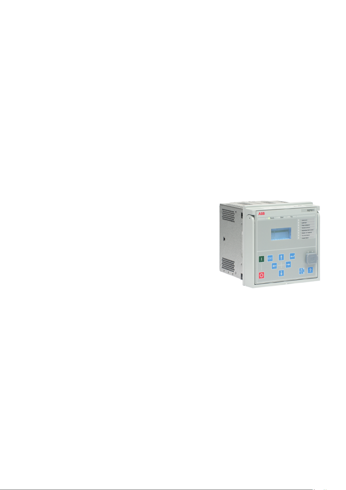
3.1 Overview
The 611 series is part of ABB’s Relion® product family. The 611 series protection
relays offer functionality within basic protection and control configurations. There are
product variants for feeder, motor, busbar and voltage protection applications. The
relays, characterized by their compactness and withdrawable-unit design, are
designed for most utility substations and industrial power systems including radial,
looped and meshed distribution networks that may also involve distributed power
generation.
The 611 series relays support the Edition 1 and Edition 2 versions of the IEC 61850
standard for communication and interoperability of substation automation devices,
including fast GOOSE messaging. The 611 series relays are able to use IEC 61850 and
Modbus® communication protocols simultaneously. The relays also support the
parallel redundancy protocol PRP and the high-availability seamless redundancy
HSR protocol. IEEE 1588 v2 is available for high-accuracy time synchronization in
all variants with an optional redundant Ethernet communication module.
3.2 Local HMI
The LHMI is used for setting, monitoring and controlling the protection relay. The
LHMI comprises the display, buttons, LED indicators and communication port.
611 series 17
Operation Manual
Page 26

REF611
Overcurrent
Earth-fault
Phase unbalance
Thermal overload
AR sequence in progress
Disturb.rec.trigged
Trip circuit failure
Breaker failure
Section 3 1MRS757453 C
611 series overview
GUID-E15422BF-B3E6-4D02-8D43-D912D5EF0360 V1 EN
Figure 2: Example of the LHMI
3.2.1 Display
The LHMI includes a graphical display that supports two character sizes. The
character size depends on the selected language. The amount of characters and rows
fitting the view depends on the character size.
Table 4: Small display
Character size
Small, mono-spaced (6 × 12 pixels) 5 20
Large, variable width (13 × 14 pixels) 3 8 or more
1) Depending on the selected language
The display view is divided into four basic areas.
1)
Rows in the view Characters per row
18 611 series
Operation Manual
Page 27

1
3
4
2
1MRS757453 C Section 3
611 series overview
GUID-24ADB995-439A-4563-AACE-1FAA193A8EF9 V1 EN
Figure 3: Display layout
1 Header
2 Icon
3 Content
4 Scroll bar (displayed when needed)
• The header area at the top of the display view shows the current location in the
menu structure.
• The icon area at the upper right corner of the display shows the current action or
user level.
Current action is indicated by the following characters.
• U: Font/Firmware is being updated
• S: Parameters are being stored
• !: Warning and/or indication
Current user level is indicated by the following characters.
• V: Viewer
• O: Operator
• E: Engineer
• A: Administrator
• The content area shows the menu content.
• If the menu contains more rows than the display can show at a time, a scroll bar
is displayed on the right.
The display is updated either cyclically or based on changes in the source data such as
parameters or events.
3.2.2 LEDs
The LHMI includes three protection indicators above the display: Ready, Start and
611 series 19
Operation Manual
Trip.
Page 28

Section 3 1MRS757453 C
611 series overview
There are also 8 programmable LEDs on front of the LHMI. The LEDs can be
configured with the LHMI, WHMI or PCM600.
3.2.3 Keypad
The LHMI keypad contains push buttons which are used to navigate in different views
or menus. With the push buttons you can give open or close commands to one object
in the primary circuit, for example, a circuit breaker, a contactor or a disconnector. The
push buttons are also used to acknowledge alarms, reset indications, provide help and
switch between local and remote control mode.
GUID-A9613A2B-0084-4D1D-A4E3-D04E72A1728E V1 EN
Figure 4: LHMI keypad with object control, navigation and command push
buttons and RJ-45 communication port
1
Close
2 Escape
3 Up
4 Enter
5 Uplink LED
6 Communication LED
7 Open
8 Left
9 Down
10 Right
11 Remote/Local
12 Help
13 Communication port
20 611 series
Operation Manual
Page 29
1MRS757453 C Section 3
611 series overview
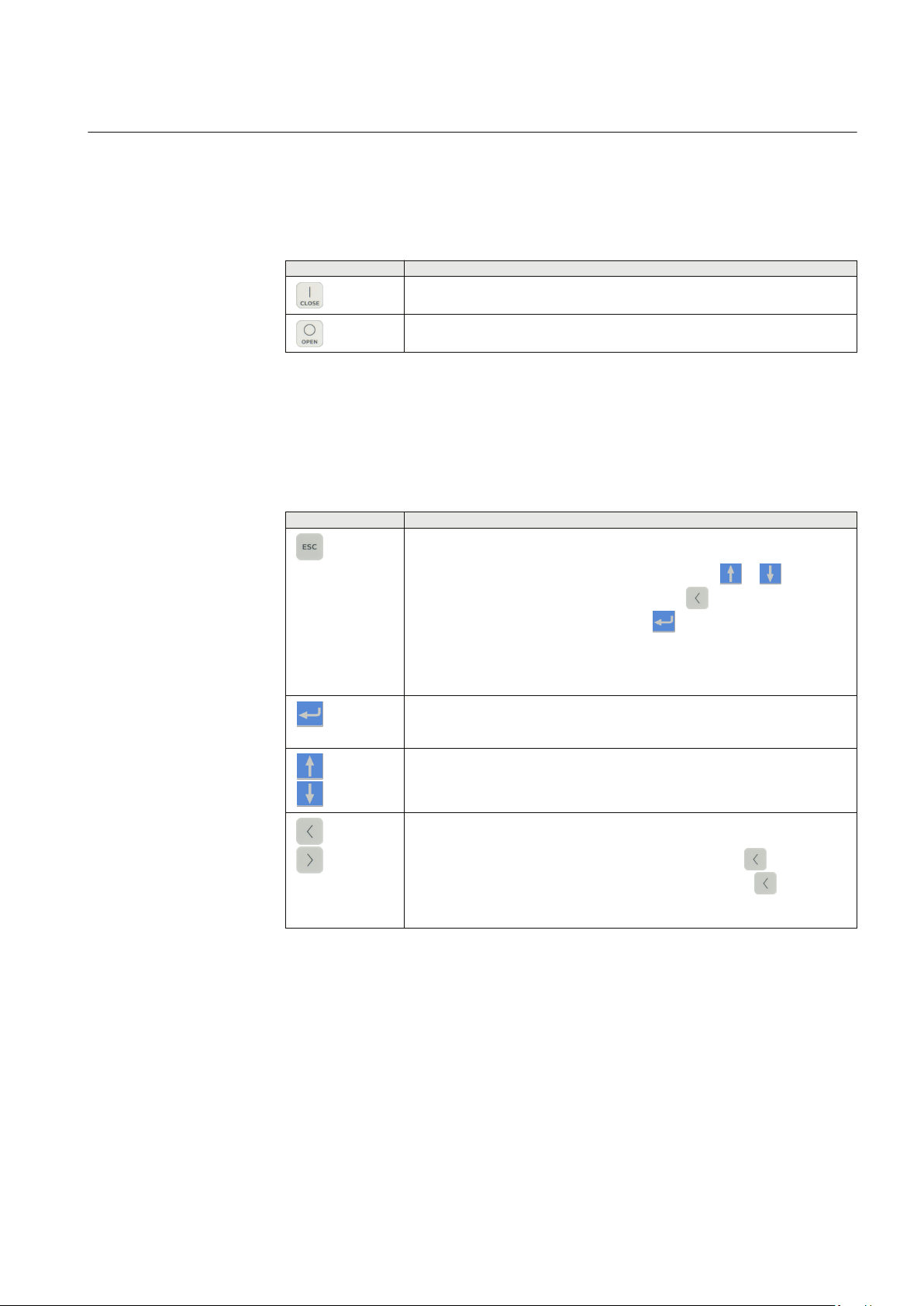
Object control
If the control position of the IED is set to local with the R/L button, the IED can be
controlled using the object control buttons.
Table 5: Object control push buttons
Name
Close
Open
Navigation
The arrow buttons are used for navigation. To scroll information, press the arrow
button several times or simply keep it pressed down.
Table 6: Navigation push buttons
Name Description
ESC
Description
Closing the object.
Opening the object.
• Leaving setting mode without saving the values.
• Cancelling certain actions.
•
Adjusting the display contrast in combination with or .
•
Changing the language in combination with .
•
Inserting a space in combination with
• Clearing indications and LEDs. The first three-second press clears the
indications. The second three-second press clears the programmable
LEDs. Requires appropriate user rights.
when editing a string.
Enter
Up
Down
Left
Right
• Entering parameter setting mode.
• Confirming a new value of a setting parameter.
• Moving up and down in menus.
• Scrolling active digits of a parameter when entering a new setting value.
• Moving left and right in menus.
• Changing the active digit of a parameter when entering a new setting value.
•
Deleting a character when editing a string by pressing .
•
Logging out, when the user is currently logged in. Press for three
seconds in the main menu.
611 series 21
Operation Manual
Page 30
Section 3 1MRS757453 C
611 series overview
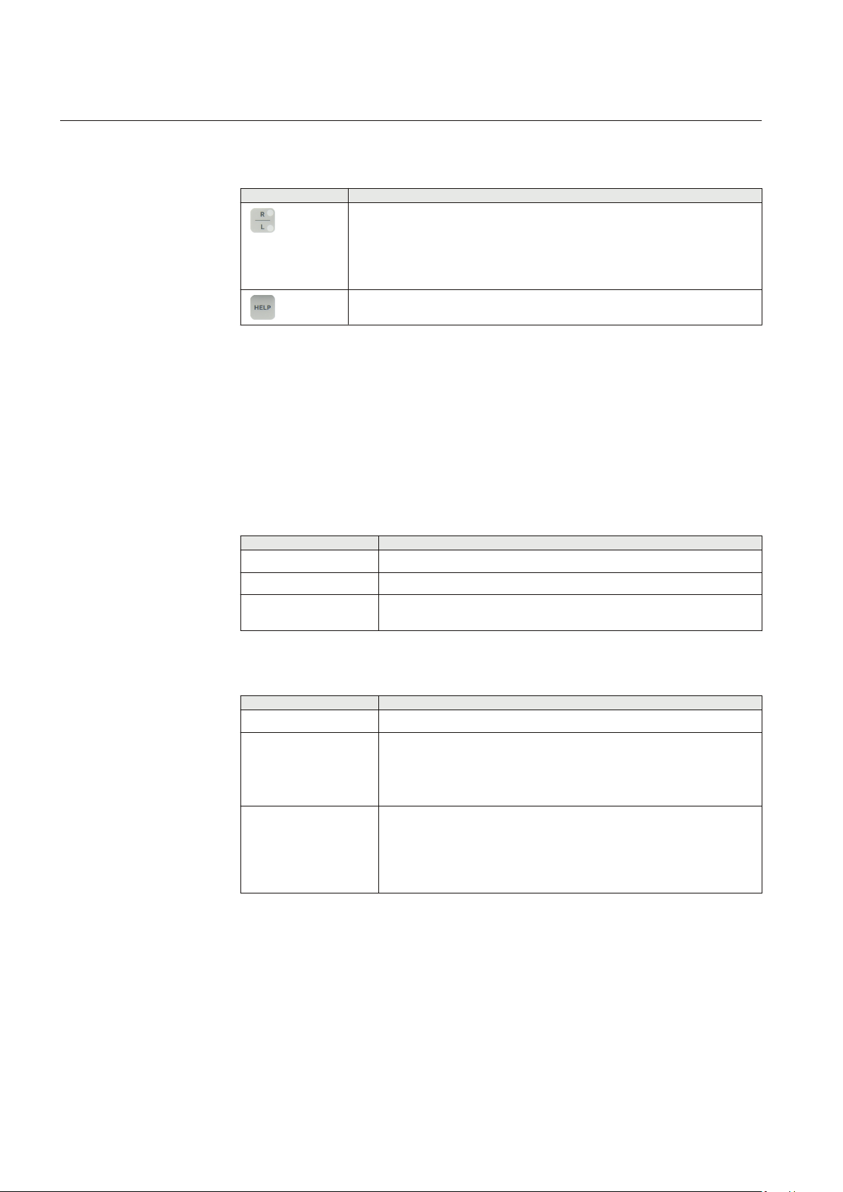
Commands
Table 7: Command push buttons
Name
R/L
Description
Changing the control position (remote or local) of the device.
• When the R LED is lit, remote control is enabled and local control disabled.
• When the L LED is lit, local control is enabled and remote control disabled.
• When none of the LEDs are lit, both control positions are disabled.
Help
Showing context sensitive help messages.
3.2.4 Local HMI functionality
3.2.4.1 Protection and alarm indication
Protection indicators
The protection indicator LEDs are Ready, Start and Trip.
Table 8: Ready LED
LED state
Off Auxiliary supply voltage is disconnected.
On Normal operation.
Flashing Internal fault has occurred or the protection relay is in test mode. Internal
Table 9: Start LED
LED state
Off Normal operation.
On A protection function has started and an indication message is displayed.
Description
faults are accompanied by an indication message.
Description
• If several protection functions start within a short time, the last start is
indicated on the display.
Flashing
22 611 series
A protection function is blocked or the protection relay is in the test and
blocked mode.
• The blocking indication disappears when the blocking is removed or
when the protection function is reset.
Operation Manual
Page 31

1MRS757453 C Section 3
611 series overview
Table 10: Trip LED
LED state Description
Off Normal operation.
On A protection function has tripped and an indication message is displayed.
• The trip indication is latching and must be reset via communication.
• If several protection functions trip within a short time, the last trip is
indicated on the display.
Alarm indicators
The 8 matrix programmable LEDs are used for alarm indication.
Table 11: Alarm indications
LED state Description
Off Normal operation. All activation signals are off.
On • Non-latched mode: activation signal is still on.
• Latched mode: activation signal is still on, or it is off but has not been
acknowledged.
• Latched flashing mode: activation signal is still on but has been
acknowledged.
Flashing
• Non-latched flashing mode: activation signal is still on.
• Latched flashing mode: activation signal is still on, or it is off but has
3.2.4.2 Parameter management
The LHMI is used to access the relay parameters. Three types of parameters can be
read and written.
• Numerical values
• String values
• Enumerated values
Numerical values are presented either in integer or in decimal format with minimum
and maximum values. Character strings can be edited character by character.
Enumerated values have a predefined set of selectable values.
Changing the function block on or off affects the visibility of its
parameters in the menu.
not been acknowledged.
Changing the value of certain relay parameters affects the visibility or
range of other parameters in the menu. This indicates which
parameters or parameter values become obsolete due to the change.
611 series 23
Operation Manual
Page 32

2
1
Section 3 1MRS757453 C
611 series overview
The relay changes the visibility or range of these parameters
immediately even before the changed values have been committed.
Some parameters may be hidden because the function is off or the
setting visibility is set to “basic” instead of “advanced”.
3.2.4.3 Front communication
The RJ-45 port in the LHMI enables front communication. Two LEDs are located
above the communication port.
• The green uplink LED on the left is lit when the cable is successfully connected
to the port.
• The yellow communication LED on the right flashes when the protection relay
communicates with the connected device.
A070816 V2 EN
Figure 5: RJ-45 communication port and indication LEDs
1
Uplink LED
2 Communication LED
When a computer is connected to the protection relay, the relay's DHCP server for the
front interface assigns an IP address to the computer. The fixed IP address for the front
port is 192.168.0.254.
3.3 Web HMI
The WHMI allows secure access to the protection relay via a Web browser. When the
Secure Communication parameter in the protection relay is activated, the Web server
is forced to take a secured (HTTPS) connection to WHMI using TLS encryption.The
WHMI is verified with Internet Explorer 8.0, 9.0, 10.0 and 11.0.
24 611 series
Operation Manual
Page 33

1MRS757453 C Section 3
611 series overview
WHMI is enabled by default. To disable the WHMI, select Main
Menu/Configuration/HMI/Web HMI mode via the LHMI. Reboot
the protection relay for the change to take effect.
WHMI offers several functions.
• Programmable LEDs and event lists
• System supervision
• Parameter settings
• Measurement display
• Disturbance records
• Fault records
• Phasor diagram
• Signal configuration
• Importing/Exporting parameters
• Report summary
The menu tree structure on the WHMI is almost identical to the one on the LHMI.
GUID-CD531B61-6866-44E9-B0C1-925B48140F3F V2 EN
Figure 6: Example view of the WHMI
The WHMI can be accessed locally and remotely.
• Locally by connecting the laptop to the protection relay via the front
communication port.
• Remotely over LAN/WAN.
611 series 25
Operation Manual
Page 34

Section 3 1MRS757453 C
611 series overview
3.3.1 Command buttons
Command buttons can be used to edit parameters and control information via the
WHMI.
Table 12: Command buttons
Name Description
Enabling parameter editing
Disabling parameter editing
Writing parameters to the protection relay
Refreshing parameter values
Printing out parameters
Committing changes to protection relay's nonvolatile flash memory
Rejecting changes
Showing context sensitive help messages
Error icon
Clearing events
Triggering the disturbance recorder manually
Saving values to TXT or CSV file format
Freezing the values so that updates are not displayed
Receiving continuous updates to the monitoring view
Deleting the disturbance record
Deleting all disturbance records
Saving the disturbance record files
Viewing all fault records
Clearing all fault records
Importing settings
Exporting settings
Table continues on next page
26 611 series
Operation Manual
Page 35

1MRS757453 C Section 3
611 series overview
Name Description
Selecting all
Clearing all selections
Refreshing the parameter list view
3.4 Authorization
Four user categories have been predefined for the LHMI and the WHMI, each with
different rights and default passwords.
The default passwords in the protection relay delivered from the factory can be
changed with Administrator user rights.
User authorization is disabled by default for the LHMI and can be
enabled with the Local override parameter via the LHMI path Main
Menu/Configuration/Authorization/Passwords. WHMI always
requires authentication.
Table 13: Predefined user categories
Username
VIEWER Read only access
OPERATOR •
ENGINEER
ADMINISTRATOR
User rights
Selecting remote or local state with
• Changing setting groups
• Controlling
• Clearing indications
• Changing settings
• Clearing event list
• Clearing disturbance records
• Changing system settings such as IP address, serial baud rate or
disturbance recorder settings
• Setting the protection relay to test mode
• Selecting language
• All listed above
• Changing password
• Factory default activation
(only locally)
For user authorization for PCM600, see PCM600 documentation.
611 series 27
Operation Manual
Page 36

Section 3 1MRS757453 C
611 series overview
3.4.1 Audit trail
The protection relay offers a large set of event-logging functions. Critical system and
protection relay security-related events are logged to a separate nonvolatile audit trail
for the administrator.
Audit trail is a chronological record of system activities that allows the reconstruction
and examination of the sequence of system and security-related events and changes in
the protection relay. Both audit trail events and process related events can be
examined and analyzed in a consistent method with the help of Event List in LHMI
and WHMI and Event Viewer in PCM600.
The protection relay stores 2048 audit trail events to the nonvolatile audit trail.
Additionally, 1024 process events are stored in a nonvolatile event list. Both the audit
trail and event list work according to the FIFO principle. Nonvolatile memory is based
on a memory type which does not need battery backup nor regular component change
to maintain the memory storage.
Audit trail events related to user authorization (login, logout, violation remote and
violation local) are defined according to the selected set of requirements from IEEE
1686. The logging is based on predefined user names or user categories. The user audit
trail events are accessible with IEC 61850-8-1, PCM600, LHMI and WHMI.
Table 14: Audit trail events
Audit trail event
Configuration change Configuration files changed
Firmware change Firmware changed
Firmware change fail Firmware change failed
Attached to retrofit test case Unit has been attached to retrofit case
Removed from retrofit test case Removed from retrofit test case
Setting group remote User changed setting group remotely
Setting group local User changed setting group locally
Control remote DPC object control remote
Control local DPC object control local
Test on Test mode on
Test off Test mode off
Reset trips Reset latched trips (TRPPTRC*)
Setting commit Settings have been changed
Time change Time changed directly by the user. Note that this is not used
View audit log
Login Successful login from IEC 61850-8-1 (MMS), WHMI, FTP or
Logout Successful logout from IEC 61850-8-1 (MMS), WHMI, FTP or
Table continues on next page
Description
when the protection relay is synchronised properly by the
appropriate protocol (SNTP, IRIG-B, IEEE 1588 v2).
Administrator accessed audit trail
LHMI.
LHMI.
28 611 series
Operation Manual
Page 37

1MRS757453 C Section 3
611 series overview
Audit trail event Description
Password change Password changed
Firmware reset Reset issued by user or tool
Audit overflow Too many audit events in the time period
Violation remote Unsuccessful login attempt from IEC 61850-8-1 (MMS),
Violation local Unsuccessful login attempt from IEC 61850-8-1 (MMS),
PCM600 Event Viewer can be used to view the audit trail events and process related
events. Audit trail events are visible through dedicated Security events view. Since
only the administrator has the right to read audit trail, authorization must be used in
PCM600. The audit trail cannot be reset, but PCM600 Event Viewer can filter data.
Audit trail events can be configured to be visible also in LHMI/WHMI Event list
together with process related events.
WHMI, FTP or LHMI.
WHMI, FTP or LHMI.
To expose the audit trail events through Event list, define the
Authority logging level parameter via Configuration/
Authorization/Security. This exposes audit trail events to all users.
Table 15: Comparison of authority logging levels
Audit trail event
Configuration change ● ● ● ● ●
Firmware change ● ● ● ● ●
Firmware change fail ● ● ● ● ●
Attached to retrofit test
case
Removed from retrofit
test case
Setting group remote ● ● ● ●
Setting group local ● ● ● ●
Control remote ● ● ●
Control local ● ● ●
Test on ● ● ●
Test off ● ● ●
Reset trips ● ● ●
Setting commit ● ●
Time change ●
View audit log ●
Login ●
Table continues on next page
None
● ● ● ● ●
● ● ● ● ●
Configurati
on change
Authority logging level
Setting
group
Setting
group,
control
Settings
edit
All
611 series 29
Operation Manual
Page 38

Section 3 1MRS757453 C
611 series overview
Audit trail event Authority logging level
Logout ●
Password change ●
Firmware reset ●
Violation local ●
Violation remote ●
3.5 Communication
The protection relay supports a range of communication protocols including IEC
61850 and Modbus®. Operational information and controls are available through
these protocols. However, some communication functionality, for example,
horizontal communication between the protection relays, is only enabled by the IEC
61850 communication protocol.
The IEC 61850 communication implementation supports all monitoring and control
functions. Additionally, parameter settings, disturbance recordings and fault records
can be accessed using the IEC 61850 protocol. Disturbance recordings are available
to any Ethernet-based application in the IEC 60255-24 standard COMTRADE file
format. The protection relay can send and receive binary signals from other devices
(so-called horizontal communication) using the IEC 61850-8-1 GOOSE profile,
where the highest performance class with a total transmission time of 3 ms is
supported. The protection relay meets the GOOSE performance requirements for
tripping applications in distribution substations, as defined by the IEC 61850
standard.
The protection relay can support five simultaneous clients. If PCM600 reserves one
client connection, only four client connections are left, for example, for IEC 61850
and Modbus.
All communication connectors, except for the front port connector, are placed on
integrated optional communication modules. The protection relay can be connected to
Ethernet-based communication systems via the RJ-45 connector (100Base-TX) or the
fiber-optic LC connector (100Base-FX). An optional serial interface is available for
RS-485 communication.
3.5.1 Self-healing Ethernet ring
For the correct operation of self-healing loop topology, it is essential that the external
switches in the network support the RSTP protocol and that it is enabled in the
switches. Otherwise, connecting the loop topology can cause problems to the
network. The protection relay itself does not support link-down detection or RSTP.
The ring recovery process is based on the aging of the MAC addresses, and the linkup/link-down events can cause temporary breaks in communication. For a better
performance of the self-healing loop, it is recommended that the external switch
30 611 series
Operation Manual
Page 39

Managed Ethernet switch
with RSTP support
Managed Ethernet switch
with RSTP support
Client A Client B
Network
Network
1MRS757453 C Section 3
611 series overview
furthest from the protection relay loop is assigned as the root switch (bridge priority
= 0) and the bridge priority increases towards the protection relay loop. The end links
of the protection relay loop can be attached to the same external switch or to two
adjacent external switches. A self-healing Ethernet ring requires a communication
module with at least two Ethernet interfaces for all protection relays.
GUID-A19C6CFB-EEFD-4FB2-9671-E4C4137550A1 V2 EN
Figure 7: Self-healing Ethernet ring solution
3.5.2 Ethernet redundancy
IEC 61850 specifies a network redundancy scheme that improves the system
availability for substation communication. It is based on two complementary
protocols defined in the IEC 62439-3:2012 standard: parallel redundancy protocol
PRP and high-availability seamless redundancy HSR protocol. Both protocols rely on
the duplication of all transmitted information via two Ethernet ports for one logical
network connection. Therefore, both are able to overcome the failure of a link or
switch with a zero-switchover time, thus fulfilling the stringent real-time
requirements for the substation automation horizontal communication and time
synchronization.
PRP specifies that each device is connected in parallel to two local area networks.
HSR applies the PRP principle to rings and to the rings of rings to achieve costeffective redundancy. Thus, each device incorporates a switch element that forwards
frames from port to port. The HSR/PRP option is available for all 611 series protection
relays.
IEC 62439-3:2012 cancels and replaces the first edition published in
2010. These standard versions are also referred to as IEC 62439-3
611 series 31
Operation Manual
Page 40

Managed
Ethernet switch
IEC 61850 PRP
Managed
Ethernet switch
Section 3 1MRS757453 C
611 series overview
Edition 1 and IEC 62439-3 Edition 2. The protection relay supports
IEC 62439-3:2012 and it is not compatible with IEC 62439-3:2010.
PRP
Each PRP node, called a double attached node with PRP (DAN), is attached to two
independent LANs operated in parallel. These parallel networks in PRP are called
LAN A and LAN B. The networks are completely separated to ensure failure
independence, and they can have different topologies. Both networks operate in
parallel, thus providing zero-time recovery and continuous checking of redundancy to
avoid communication failures. Non-PRP nodes, called single attached nodes (SANs),
are either attached to one network only (and can therefore communicate only with
DANs and SANs attached to the same network), or are attached through a redundancy
box, a device that behaves like a DAN.
GUID-AA005F1B-A30B-48F6-84F4-A108F58615A2 V1 EN
Figure 8: PRP solution
In case a laptop or a PC workstation is connected as a non-PRP node to one of the PRP
networks, LAN A or LAN B, it is recommended to use a redundancy box device or an
Ethernet switch with similar functionality between the PRP network and SAN to
remove additional PRP information from the Ethernet frames. In some cases, default
PC workstation adapters are not able to handle the maximum-length Ethernet frames
with the PRP trailer.
There are different alternative ways to connect a laptop or a workstation as SAN to a
PRP network.
32 611 series
Operation Manual
Page 41

IEC 61850 HSR
Ethernet
switch
Redundancy
box
Redundancy
box
Redundancy
box
X
X
Unicast tr affic
Message is recognized as a
duplicat e and is
immediate ly forwarded
X
Sending de vice removes
the mes sage from the ring
Devices not supporting HSR
Sender
Receiver
1MRS757453 C Section 3
611 series overview
• Via an external redundancy box (RedBox) or a switch capable of connecting to
PRP and normal networks
• By connecting the node directly to LAN A or LAN B as SAN
• By connecting the node to the protection relay's interlink port
HSR
HSR applies the PRP principle of parallel operation to a single ring, treating the two
directions as two virtual LANs. For each frame sent, a node, DAN, sends two frames,
one over each port. Both frames circulate in opposite directions over the ring and each
node forwards the frames it receives, from one port to the other. When the originating
node receives a frame sent to itself, it discards that to avoid loops; therefore, no ring
protocol is needed. Individually attached nodes, SANs, such as laptops and printers,
must be attached through a “redundancy box” that acts as a ring element. For example,
a 615 or 620 series protection relay with HSR support can be used as a redundancy
box.
GUID-B24F8609-0E74-4318-8168-A6E7FCD0B313 V1 EN
Figure 9: HSR solution
3.5.3 Secure communication
The protection relay supports secure communication for WHMI and file transfer
protocol. If the Secure Communication parameter is activated, protocols require TLS
based encryption method support from the clients. In this case WHMI must be
Secure Communication is “ON”.
connected from a Web browser using the HTTPS protocol and in case of file transfer
the client must use FTPS.
As a factory default,
611 series 33
Operation Manual
Page 42

Section 3 1MRS757453 C
611 series overview
3.6 PCM600 tool
Protection and Control IED Manager PCM600 offers all the necessary functionality
to work throughout all stages of the protection relay life cycle.
• Planning
• Engineering
• Commissioning
• Operation and disturbance handling
• Functional analysis
The whole substation configuration can be controlled and different tasks and
functions can be performed with the individual tool components. PCM600 can
operate with many different topologies, depending on the customer needs.
For more information, see the PCM600 documentation.
3.6.1 Connectivity packages
A connectivity package is a software component that consists of executable code and
data which enables system tools to communicate with a protection relay. Connectivity
packages are used to create configuration structures in PCM600. The latest PCM600
and connectivity packages are backward compatible with older protection relay
versions.
A connectivity package includes all the data which is used to describe the protection
relay. For example, it contains a list of the existing parameters, data format used, units,
setting range, access rights and visibility of the parameters. In addition, it contains
code which allows software packages that use the connectivity package to properly
communicate with the protection relay. It also supports localization of text even when
it is read from the protection relay in a standard format such as COMTRADE.
Update Manager is a tool that helps in defining the right connectivity package versions
for different system products and tools. Update Manager is included with the products
that use connectivity packages.
3.6.2 PCM600 and relay connectivity package version
• Protection and Control IED Manager PCM600 Ver.2.7 or later
• REB611 Connectivity Package Ver.2.0 or later
• REF611 Connectivity Package Ver.2.0 or later
• REM611 Connectivity Package Ver.2.0 or later
• REU611 Connectivity Package Ver.2.0 or later
34 611 series
Operation Manual
Page 43

1MRS757453 C Section 3
611 series overview
Download connectivity packages from the ABB Web site
http://www.abb.com/substationautomation or directly with Update
Manager in PCM600.
611 series 35
Operation Manual
Page 44

36
Page 45

1MRS757453 C Section 4
Using the HMI
Section 4 Using the HMI
4.1 Using the local HMI
To use the LHMI, logging in and authorization are required. Password authorization
is disabled by default and can be enabled via the LHMI.
To enable password authorization, select Main menu/
Configuration/Authorization/Passwords. Set the Local override
parameter to “False”.
4.1.1 Logging in
1.
Press
2.
Press or to select the user level.
GUID-7B40EC73-2324-4E9A-9DF7-CC742744EC1B V1 EN
Figure 10: Selecting access level
3.
Confirm the selection with .
4. Enter the password when prompted digit by digit.
•
Activate the digit to be entered with and .
•
Enter the character with and .
or or to activate the login procedure.
GUID-C8BDDF55-EB8B-42AD-8184-3939BF51B4C4 V1 EN
Figure 11: Entering password
5.
Press to confirm the login.
•
To cancel the procedure, press .
611 series 37
Operation Manual
Page 46

Section 4 1MRS757453 C
Using the HMI
GUID-39601B65-8E32-49F7-AE8A-C16B71770D69 V1 EN
Figure 12: Error message indicating wrong password
The current user level is shown on the display's upper right corner in
the icon area.
4.1.2 Logging out
An automatic logout occurs 30 seconds after the backlight timeout.
1.
Press for three seconds in the main menu.
2.
To confirm logout, select Yes and press
GUID-65BD2160-B3FF-4FD0-8028-C5F0CB67FE54 V1 EN
Figure 13: Logging out
•
To cancel logout, press .
4.1.3 Turning the display backlight on
The display backlight is normally off. It turns on during the display test at power up.
• To turn on the backlight manually, press any LHMI push button.
The backlight turns on and the panel is ready for further operations.
If the panel has not been used for a predefined timeout period, the backlight is
switched off. The user is logged out from the current user level 30 seconds after the
display backlight has turned off.
.
The display returns to the default view and all unconfirmed operations such as
parameter editing and breaker selection are cancelled.
38 611 series
Operation Manual
Page 47

1MRS757453 C Section 4
Using the HMI
Change the backlight timeout period in Main menu/
Configuration/HMI/Backlight timeout.
4.1.4 Selecting local or remote use
The control position of the protection relay can be changed with the R/L button. In
local position primary equipment, such as circuit breakers or disconnectors, can be
controlled via the LHMI. In remote position, control operations are possible only from
a higher level, that is from a control center.
•
Press for two seconds.
• When the L LED is lit, local control is enabled and remote control disabled.
• When the R LED is lit, remote control is enabled and local control disabled.
• When neither of the LEDs is lit, both control positions are disabled.
• When the L and R LEDs are lit, both remote and local control are enabled.
By default, the control position cannot be local and remote
simultaneously. See the technical manual for more information
on local and remote control.
To control the protection relay, log in with the appropriate user
rights.
4.1.5 Identifying the device
The Information menu includes detailed information about the device, such as
revision and serial number.
The protection relay information is shown on the display for a few seconds when the
device starts. The same information is also found in the protection relay menu.
1. Select Main menu/Information.
2.
Select a submenu with
and .
611 series 39
Operation Manual
Page 48

Section 4 1MRS757453 C
Using the HMI
GUID-36916877-1917-4472-AA11-37897C5FD709 V1 EN
Figure 14: Selecting a submenu
3.
Enter the submenu with .
4.
Browse the information with and .
GUID-2437E75E-0B00-4B47-89D2-FD4E5690BCC6 V1 EN
Figure 15: Protection relay information
4.1.5.1 Identifying relay's IEC 61850 version
The relay's IEC 61850 version information identifies if the relay is configured as
Edition 1 or Edition 2 device.
1. Select Main menu/Information/System identifiers.
2.
Enter the submenu with .
GUID-D8F6EB65-75D5-4EE6-BC96-1153FC832AB3 V1 EN
Figure 16: Identifying IEC 61850 version
4.1.6 Adjusting the display contrast
Adjust the display contrast anywhere in the menu structure to obtain optimal
readability.
•
To increase the contrast, press simultaneously and .
•
To decrease the contrast, press simultaneously
40 611 series
and .
Operation Manual
Page 49

1MRS757453 C Section 4
Using the HMI
The selected contrast value is stored in the non-volatile memory if you are logged in
and authorized to control the protection relay. After an auxiliary power failure, the
contrast is restored.
4.1.7 Changing the local HMI language
1.
Select Main menu/Language and press .
2.
Change the language using or .
3.
Press
4. Commit the changes.
to confirm the selection.
GUID-8588E7BB-6C58-4D6E-8690-27D46738B25F V1 EN
Figure 17: Changing the LHMI language
To change the language using a shortcut, press and
simultaneously anywhere in the menu.
4.1.8 Changing display symbols
Use the keypad to switch between the display symbols IEC 61850, IEC 60617 and
IEC-ANSI.
1. Select Main Menu/Configuration/HMI/FB naming convention and press
.
2.
Change the display symbols with or .
3.
Press
to confirm the selection.
The protection relay has to be rebooted if the WHMI display symbols
are changed. With the LHMI, the change takes effect immediately.
4.1.9 Changing setting visibility
The basic settings contain the most used parameters. The advanced settings contain all
parameters.
611 series 41
Operation Manual
Page 50

Section 4 1MRS757453 C
Using the HMI
1.
Select Main Menu/Configuration/HMI/Setting visibility and press .
2.
Change the setting visibility with
shown.
Basic
•
Advanced
•
3.
Press to confirm the selection.
GUID-ECF76371-3DF5-4833-966A-447D52FCF492 V1 EN
Figure 18: Viewing basic parameters
or to select which parameters are
4.1.10 Navigating in the menu
Navigate the menus and change the display views on the screen with the keypad.
•
To move up or down in a menu, press or .
•
To move downwards in the menu tree, press
•
To move upwards in the menu tree, press .
•
To enter setting mode, press .
•
To leave setting mode without saving, press .
4.1.10.1 Menu structure
The Main menu contains main groups which are divided further into more detailed
submenus.
• Control
• Events
• Measurements
• Disturbance records
• Settings
• Configuration
• Monitoring
• Tests
• Information
• Clear
• Language
.
42 611 series
Operation Manual
Page 51

1MRS757453 C Section 4
Using the HMI
4.1.10.2 Scrolling the display
If a menu contains more rows than the display can show at a time, a scroll bar is
displayed on the right.
GUID-3DB7835C-EA13-46C3-AAF5-455C07D454EC V1 EN
Figure 19: Scroll bar on the right
•
To scroll the view upwards, press .
•
To scroll the view downwards, press .
•
To jump from the last row to the first row, press again.
•
Press to jump from the first row to the last row.
•
To scroll parameter names and values that do not fit the screen, press . Press
once to return to the beginning.
4.1.10.3 Changing the default view
The default view of the display is Measurements unless set otherwise.
1.
Select Main menu/Configuration/HMI/Default view and press .
2.
Change the default view with or .
3.
Press to confirm the selection.
4.1.11 Browsing setting values
1.
Select Main menu/Settings/Settings and press
2.
Select the setting group to be viewed with or .
.
611 series 43
Operation Manual
Page 52

Section 4 1MRS757453 C
Using the HMI
GUID-3A58D472-E755-4244-9B1C-EA18EB6B5709 V1 EN
Figure 20: Selecting a setting group
3.
Press to confirm selection.
4.
To browse the settings, scroll the list with and and to select a submenu
press . To move back to the list, press .
GUID-E1C19F9C-079D-479C-BAF0-71E6E2FAF112 V1 EN
Figure 21: Example of submenus in the Settings menu
4.1.12 Editing values
• To edit values, log in with the appropriate user rights.
Changing the function block on or off affects to the visibility of its
parameters in the menu. Setting function block off hides the function
parameters. When changing function block on or off the parameters'
visibility changes immediately. Commit the settings for the activation
of the function.
Changing the value of certain relay parameters affects the visibility or
range of other parameters in the menu. This indicates which
parameters or parameter values become obsolete due to the change.
The relay changes the visibility or range of these parameters
immediately. Commit the settings for the activation of the function.
4.1.12.1 Editing numerical values
1. Select Main menu/Settings and then a setting.
The last digit of the value is active.
44 611 series
Operation Manual
Page 53

1MRS757453 C Section 4
Using the HMI
• When the symbol in front of the value is ↑, the active value can only be
increased.
• When the symbol is ↓, the active value can only be decreased.
• When the symbol in front of the value is ↕, the active value can either be
increased or decreased.
GUID-91310FC1-E8FB-452E-B9B6-4D65C874278C V1 EN
Figure 22: Last digit is active and it can only be increased
2.
Press to increase or to decrease the value of an active digit.
One press increases or decreases the value by a certain step. For integer values,
the change is 1, 10, 100 or 1000 (...) depending on the active digit. For decimal
values, the change can be fractions 0.1, 0.01, 0.001 (...) depending on the active
digit.
For parameters with defined steps, digits smaller than the step
value cannot be edited.
3.
Press or to move the cursor to another digit.
4. To select the minimum or maximum value, select the arrow symbol in front of
the value.
•
To set the value to the maximum, press .
•
To set the value to the minimum, press .
GUID-604A2ED9-E1A7-4986-8CDD-92E43188CA48 V1 EN
Figure 23: Arrow symbol is active, the value is set to the maximum
After pressing , the previous value can be restored by pressing once, and
vice versa. Another press of or sets the value to the lower or higher limit.
The symbol in front of the value is ↕, when the previous value is shown.
611 series 45
Operation Manual
Page 54

Section 4 1MRS757453 C
Using the HMI
GUID-F65419AD-767F-488E-9915-4BBEB859D15A V1 EN
Figure 24: Restoring the previous value
4.1.12.2 Editing string values
1. Activate the setting mode and select a setting.
When editing string values, the cursor moves to the first character.
2.
Press
One press changes the value by one step.
3.
Press to move the cursor to the right. Press to delete the character on the
left side of the cursor.
or to change the value of an active character.
4.1.12.3 Editing enumerated values
1. Activate the setting mode and select a setting.
When editing an enumerated value, the selected value is shown inverted.
2.
Press
or to change the value of an active enumerated value.
One press changes the enumerated value by one step in the parameter specific
order.
4.1.13 Committing settings
Editable values are stored either in RAM or in non-volatile flash memory. Values
stored in flash memory are in effect also after reboot.
Some parameters have an edit-copy. If editing is cancelled, the values with an editcopy are immediately restored to the original value. The values without an edit-copy,
such as string values, are restored to the original value only after a reboot even though
the edited value is not stored in the flash memory.
1.
Press
2.
Press to move upwards in the menu tree.
3.
To save the changes in non-volatile memory, select Yes and press .
to confirm any changes.
46 611 series
Operation Manual
Page 55

1MRS757453 C Section 4
Using the HMI
GUID-2366EB35-75C9-48AC-8D11-E2B058BCF996 V1 EN
Figure 25: Confirming settings
•
To exit without saving changes, select No and press .
• If the parameter has an edit-copy, the original parameter value is
restored.
• If the parameter does not have an edit-copy, the edited parameter
value remains visible until the protection relay is rebooted.
However, the edited value is not stored in non-volatile memory and
the reboot restores the original value.
•
To cancel saving settings, select Cancel and press
.
After certain parameters are changed, the protection relay has to be
restarted.
4.1.14 Clearing and acknowledging
The Clear view is used to reset, acknowledge or clear all messages and indications,
including LEDs and latched outputs as well as registers and recordings. Events and
alarms assigned to programmable LEDs are cleared in the Clear view as well.
1. Select Main menu/Clear to activate the clear menu.
GUID-6A5EE8B5-5F4B-4F35-958D-645F1134D69B V1 EN
Figure 26: Clear view
2.
Select the item to be cleared with or .
3.
Press , change the value with or and press again.
The item is now cleared.
4. Repeat steps 2 and 3 to clear other items.
611 series 47
Operation Manual
Page 56

Section 4 1MRS757453 C
Using the HMI
Use the button as a shortcut for clearing. The first three-second
press clears the indications. The second three-second press clears the
programmable LEDs.
4.1.15 Using the local HMI help
1.
Press
2.
Scroll the text with or if the help text exceeds the display area.
3.
To close the help, press .
to open the help view.
4.2 Using the Web HMI
WHMI is enabled by default. As secure communication is enabled by default, the
WHMI must be accessed from a Web browser using the HTTPS protocol.
If the WHMI was previously disabled, it can be enabled again via the LHMI.
1. To enable the WHMI, select Main menu/Configuration/HMI/Web HMI
mode via the LHMI.
2. Reboot the relay for the change to take effect.
3. Log in with the proper user rights to use the WHMI.
To establish a remote WHMI connection to the protection relay,
contact the network administrator to check the company rules for IP
and remote connections.
Disable the Web browser proxy settings or make an exception to the
proxy rules to allow the protection relay's WHMI connection, for
example, by including the relay's IP address in Internet Options/
Connections/LAN Settings/Advanced/Exceptions.
4.2.1 Logging in
1. Open Internet Explorer.
2. Type the protection relay's IP address in the Address bar and press ENTER.
3. Type the username with capital letters.
4. Type the password.
48 611 series
Operation Manual
Page 57

1MRS757453 C Section 4
Using the HMI
A070923 V5 EN
Figure 27: Entering username and password to use the WHMI
5. Click OK.
The language file starts loading and the progress bar is displayed.
4.2.2 Logging out
The user is logged out after session timeout. The timeout can be set in Main menu/
Configuration/HMI/Web HMI timeout.
• To log out manually, click Logout on the menu bar.
4.2.3 Identifying device
The Information menu includes detailed information about the device, for example,
revision and serial number.
1. Click the Information menu in the left navigation bar.
2. Click a submenu to see the data.
611 series 49
Operation Manual
Page 58

Section 4 1MRS757453 C
Using the HMI
GUID-0526D2B8-9C7C-4C29-9E1C-C9DF549B2970 V1 EN
Figure 28: Device information
4.2.4 Navigating in menus
The menu tree structure on the WHMI is almost identical to the one on the LHMI.
• Use the menu bar to access different views.
• The General view shows the protection relay version and status.
• The Events view contains a list of events produced by the application
configuration.
• The Programmable LEDs view shows the status of programmable LEDs.
• The Phasor diagrams view shows phasor diagrams.
• The Disturbance records view shows the list of disturbance records.
• Signal configuration
• Logout ends the session.
50 611 series
Operation Manual
Page 59

1MRS757453 C Section 4
Using the HMI
GUID-C08AA4D5-0F4E-4DC5-9194-8338A19761AC V1 EN
Figure 29: Navigating in Web HMI menus
4.2.4.1 Menu structure
The Main menu contains main groups which are divided further into more detailed
submenus.
• Control
• Events
• Measurements
• Disturbance records
• Settings
• Configuration
• Monitoring
• Tests
• Information
• Clear
• Language
• Parameter list
• WHMI settings
611 series 51
Operation Manual
Page 60

Section 4 1MRS757453 C
Using the HMI
4.2.5 Showing parameters
Some function blocks have a function-specific On/Off setting. When the function
setting is “Off”, all settings are hidden and when the function setting is “On”, all
settings are visible based on the other visibility and hiding rules.
Switch a function block on or off via the Operation parameter under
the required function block.
GUID-F6EDA317-5965-463D-9335-0FD22A315D28 V1 EN
Figure 30: Function block On
52 611 series
Operation Manual
Page 61

1MRS757453 C Section 4
Using the HMI
GUID-9C2AD6B3-594A-4BCC-A2B9-5A875962D368 V1 EN
Figure 31: Function block Off
The Parameter list page offers filtering functionality where only chosen parameters
are displayed, saved or printed. There are various options for filtering.
• Enabled settings hides settings of disabled function blocks.
• Writable settings displays only writable settings. This option is checked by
default.
• Basic settings displays only basic settings.
• Setting group displays only settings of the selected setting group. With “All”
selected, all setting groups are displayed.
Options can be combined. For example, with the Enabled settings and Writable
settings selected, only enabled and writable settings are displayed. If none of the
options is selected, all settings are displayed.
The values “Basic” or "Advanced" of the Setting visibility parameter
in Main Menu/Configuration/HMI have no effect on the Parameter
list page. This page has its own Basic settings option which can be
used to hide or show the advanced settings on the Parameter list page.
GUID-B0106F5F-4798-475B-9DFB-58921B167310 V1 EN
Figure 32: Parameter list filter
1. Click Parameter list in the left navigation bar.
611 series 53
Operation Manual
Page 62

Section 4 1MRS757453 C
Using the HMI
GUID-93613E3F-4CD3-4578-9F97-424282B1228B V2 EN
Figure 33: Displaying parameters
2. Select only those settings that are wanted to be shown and click Refresh. If
nothing is selected, all settings are shown.
54 611 series
Operation Manual
Page 63

1MRS757453 C Section 4
Using the HMI
GUID-C2331A22-4BC6-4D24-9B8F-A8EB7A22CCCA V1 EN
Figure 34: Enabled settings
3. Select text (.txt) or comma separated values (.csv) file format and click Save to
save the settings.
4. Click Print to print all the selected parameters.
4.2.6 Editing values
1. Select a menu in the left navigation bar.
2. Click a submenu to see function blocks.
3. Click a function block to see the setting values.
4. Click Enable Write.
Some parameters, for example the Web HMI mode, cannot be
set via the WHMI.
611 series 55
Operation Manual
Page 64

Section 4 1MRS757453 C
Using the HMI
GUID-C6FA8F5E-19CC-47AD-A000-8DFF91B3FFE7 V2 EN
Figure 35: Enable writing to edit a value
The selected setting group is shown in the Setting Group drop-down list. The
active setting group is indicated with an asterisk *.
5. Edit the value.
• The minimum, maximum and step values for a parameter are shown in the
Min., Max. and Step columns.
•
Setting group values are indicated with .
56 611 series
Operation Manual
Page 65

1MRS757453 C Section 4
Using the HMI
GUID-35C049F6-D716-451D-9886-CFC607295675 V2 EN
Figure 36: Editing a value
• If the entered value is within the accepted value range, the selection is
highlighted in green. If the value is out of range, the row is highlighted in
red and a warning dialog box is displayed. Write to IED is unavailable.
GUID-12C28E34-2871-423A-B9D9-A03FB55362AC V2 EN
Figure 37: Warning indicating that the entered value is incorrect
• If writing values fails, a warning dialog box is displayed.
611 series 57
Operation Manual
Page 66

Section 4 1MRS757453 C
Using the HMI
GUID-E85F77ED-C27F-426B-AAAD-9C6E10994A7C V2 EN
Figure 38: Warning indicating that the values were not written to the
IED
If writing is enabled accidentally, click Disable Write. Disable
Write cannot be selected when a value has already been written to the
protection relay. After clicking Write to IED, click either Commit or
Reject.
4.2.7 Committing settings
Editable values are stored either in RAM or a nonvolatile flash memory. Values stored
in the flash memory are in effect also after a reboot.
Some parameters have an edit-copy. If editing is cancelled, the values with an editcopy are immediately restored to the original value. The values without an edit-copy,
such as string values, are restored to the original value only after a reboot even though
the edited value is not stored in the flash memory.
1. Click Write to IED after editing parameter values to put the values into
protection relay's database for use.
58 611 series
Operation Manual
Page 67

1MRS757453 C Section 4
Using the HMI
GUID-F286D262-E9AB-4168-8BF1-FC37688D91BF V1 EN
Figure 39: Writing values to protection relay
The values are not stored to the flash memory.
2. Click Commit to write the values to the flash memory.
• Click Reject to cancel saving settings.
• If the parameter has an edit-copy, the original parameter value is
restored.
• If the parameter does not have an edit-copy, the edited parameter
value remains visible until the protection relay is rebooted.
However, the edited value is not stored in the nonvolatile memory
and thus the reboot restores the original value.
GUID-88F499E6-799A-44D0-869A-1F01E7ED6722 V2 EN
Figure 40: Committing changes
Committing values takes a few seconds.
611 series 59
Operation Manual
Page 68

Section 4 1MRS757453 C
Using the HMI
If the values are not committed, they are not taken into use and they are
lost after a reboot.
4.2.8 Clearing and acknowledging
All messages and indications, including LEDs and latched outputs as well as registers
and recordings, can be reset, acknowledged or cleared using the Clear menu.
1. Click Clear in the left navigation bar.
GUID-BD2CC4E6-6363-4EEA-9402-415901CC74FA V2 EN
Figure 41: Selecting clear menu
2. In the New Value list, select Clear to choose the item to be cleared.
3. Click Write to IED.
60 611 series
Operation Manual
Page 69

1MRS757453 C Section 4
Using the HMI
GUID-3CAE395C-EC4D-409A-99EB-C3434680BB61 V2 EN
Figure 42: Clearing indications and LEDs
4.2.9 Selecting programmable LEDs view
The programmable LEDs view shows the status of the programmable LEDs. These
are the same LEDs that are located on the upper right side of the LHMI panel.
• Click Programmable LEDs on the menu bar.
611 series 61
Operation Manual
Page 70

Section 4 1MRS757453 C
Using the HMI
GUID-20C268F8-B2BA-41E1-A17D-5DBAE8CEFA2F V2 EN
Figure 43: Monitoring programmable LEDs
4.2.10 Selecting event view
The event view contains a list of events produced by the application configuration.
When the event page is opened, it displays up to 100 latest events at one time. The
event list is updated automatically.
1. Click Events on the menu bar.
62 611 series
Operation Manual
Page 71

1MRS757453 C Section 4
Using the HMI
GUID-4E351C8C-EE76-46F5-B83B-14230676BCE8 V2 EN
Figure 44: Monitoring events
2. Click Freeze to stop updating the event list.
3. Select a page from the drop-down list to view older events or select View all to
show all events on the same page.
GUID-4FD2F9CC-D690-4A68-8E17-E6DE420ADED9 V2 EN
Figure 45: Events view
4. To save the events in TXT or CSV file formats, select the file format from the
drop-down list and click Save.
611 series 63
Operation Manual
Page 72

Section 4 1MRS757453 C
Using the HMI
The CSV file can be opened with a spreadsheet program such as
OpenOffice.org Calc or Microsoft Excel.
5. Click Clear events to clear all events from the protection relay.
6. Click Print to print all the selected events.
4.2.11 Selecting disturbance records view
Disturbance records are listed in the disturbance records view.
• Click Disturbance records on the menu bar.
GUID-FD3ED365-053B-4613-B290-2F3F46D04A0D V1 EN
Figure 46: Selecting disturbance records view
4.2.11.1 Saving disturbance records
1. Click Disturbance records on the menu bar.
2. To save the disturbance record files, click the icon in the Download Files
column of the record.
64 611 series
Operation Manual
Page 73

1MRS757453 C Section 4
Using the HMI
GUID-76B94DE7-6020-4466-833A-2A22DB6A4367 V1 EN
Figure 47: Saving a disturbance record
3. Open the disturbance record files with a suitable program.
4.2.11.2 Triggering disturbance recorder manually
1. Click Disturbance records on the menu bar.
2. Click Manual trigger.
GUID-BD629C96-3A49-47C3-B09B-B2776C9CF467 V2 EN
Figure 48: Manual triggering
611 series 65
Operation Manual
Page 74

Section 4 1MRS757453 C
Using the HMI
4.2.11.3 Deleting disturbance records
1. Click Disturbance records on the menu bar.
2. Delete records.
• Click Delete all to delete all records.
• Select one or more recordings and click Delete to delete selected records.
GUID-9B5D6FB6-68F0-472F-B23D-6369158D6BD7 V2 EN
Figure 49: Deleting disturbance records
3. Click OK to confirm or Cancel to cancel the deletion.
4.2.12 Selecting phasor diagrams
Install or enable the SVG plugin to view the phasor diagrams, if
needed.
1. Click Phasor diagrams on the menu bar.
66 611 series
Operation Manual
Page 75

1MRS757453 C Section 4
Using the HMI
GUID-BC13067A-6C27-4532-9BD8-FD9BA724BFFF V1 EN
Figure 50: Monitoring phasors
2. Toggle the diagram visibility by selecting the diagram from the drop-down
menu.
GUID-91F00B72-85EE-4577-B828-7B6E158F4CBF V1 EN
Figure 51: Toggling the diagram visibility
611 series 67
Operation Manual
Page 76

Section 4 1MRS757453 C
Using the HMI
Visible diagrams are indicated with an asterisk *.
3. Change the size of the diagram by changing the zoom value.
GUID-D1C26F94-FCD1-4A0B-AE94-A3E4DACB8682 V1 EN
Figure 52: Zooming the diagram
4. Click Freeze to stop updating the phasor diagram.
No updates are displayed in the diagram.
68 611 series
Operation Manual
Page 77

1MRS757453 C Section 4
Using the HMI
GUID-8BA2E56F-8828-4C5E-807C-F1F780F6E0C8 V1 EN
Figure 53: The arrow extends outside the circle if the current value is too
high
4.2.13 Selecting fault records
1. Fom the main menu, select Monitoring/Recorded data/Fault record or click
Fault records on the menu bar to view a list of all available fault records.
2. Click a record from the Fault records list to open the fault record details
view.
3. To go back to the list view, click Fault records on the menu bar or click the View
all button.
4. To save the records in TXT or CSV file formats, select the format from the File
format drop-down list and click Save.
• When the fault record details view is shown, only the shown fault record
is saved.
• When fault record list view is shown, all fault records are saved.
5. To clear all fault records from the protection relay, click Clear records.
This can be done only when the fault record list view is shown.
6. To print all fault records, click Print when the fault record list view is shown.
7. To print only one record, open it in the details view and click Print.
611 series 69
Operation Manual
Page 78

Section 4 1MRS757453 C
Using the HMI
GUID-2D4814EC-F4F7-4FF6-9E40-65D8C7F83487 V1 EN
Figure 54: Fault record list view
GUID-0E215160-B6E8-4ACB-B91A-DEAC98501FFC V1 EN
Figure 55: Fault record details view
70 611 series
Operation Manual
Page 79

1MRS757453 C Section 4
Using the HMI
4.2.14 Selecting signal configuration
The signal configuration view provides an easy tool to manage the application
configuration, simplifying the configuration work. The signal configuration is done
with three switch group functions including input switch group ISWGAPC, output
switch group OSWGAPC and selector switch group SELGAPC.
1. Click Signal configuration on the menu bar to open the overview page.
The switch groups used in the protection relay are categorized into four logical
groups.
• Binary inputs
• GOOSE
• Internal signals
• Binary outputs and LEDs
Each group is represented by an area enclosed in a rectangle with a general
description text.
GUID-3DC3C22C-ED52-4C1C-A9E8-5559DEA5724D V2 EN
Figure 56: Overview
2. Click the corresponding area to view a specific logical group.
The switch groups included in the logical group are shown as a matrix view on
the respective page. This view allows to change or map the connections from
binary inputs to functions, GOOSE signals to functions, functions to functions,
functions to binary outputs and functions to LEDs through corresponding switch
group functions.
611 series 71
Operation Manual
Page 80

Section 4 1MRS757453 C
Using the HMI
GUID-EAB8BB7D-C914-436D-8DDC-643EDF49ED40 V2 EN
Figure 57: Binary input configuration
GUID-B804DF59-FFE6-42FE-8E41-5A2A125DCD46 V2 EN
Figure 58: GOOSE configuration
72 611 series
Operation Manual
Page 81

1MRS757453 C Section 4
Using the HMI
GUID-4CF3B8E5-F756-4892-AE71-C4AA5895F075 V2 EN
Figure 59: Internal signal configuration
611 series 73
Operation Manual
Page 82

Section 4 1MRS757453 C
Using the HMI
GUID-085A93F1-AD8B-42E4-9362-407C7057EA20 V2 EN
Figure 60: Binary outputs and LEDs configuration
3. On the Binary Outputs and LEDs Configuration matrix view, click Expand
all to see the expanded page for configuring individual OSWGAPC instances.
Use the Expand all and Collapse all buttons to move from the Binary Outputs
and LEDs Configuration overview page to the more detailed view and back.
74 611 series
Operation Manual
Page 83

1MRS757453 C Section 4
Using the HMI
GUID-17AA5E7D-88EA-4B1D-AC4E-20EDBAC329F6 V1 EN
Figure 61: Binary outputs and LEDs configuration expanded view
4. Click Enable Write to edit field values.
Figure 62 shows an example view of updating or changing the input signal
configuration. One of the binary input channels has been mapped to one
blocking input of a protection function through input switch group ISWGAPC
and selector switch group SELGAPC functions.
• Click one of the input switch group ISWGAPC connection channel shown
in green.
• Click and select the binary input in the selector switch group SELGAPC
function shown in green.
• Write the connection setting to IED and refresh values.
611 series 75
Operation Manual
Page 84

Section 4 1MRS757453 C
Using the HMI
GUID-B6CE346B-D178-4FD1-B77C-084430E985AF V1 EN
Figure 62: Example view of changing binary input connections
For more information on editing field values, see the
corresponding chapter.
4.2.15 Import and export of settings
Protection relay's setting parameters can be imported and exported in the XRIO file
format.
4.2.15.1 Exporting settings
Relay setting parameters can be exported in XRIO file format.
1. Click Import/Export on the menu bar.
2. Click Export Settings. The export file includes all parameters except status
parameters and parameters writable only in LHMI.
76 611 series
Operation Manual
Page 85

1MRS757453 C Section 4
Using the HMI
GUID-7BF72874-B597-4EB9-B37D-72D58578647D V1 EN
Figure 63: Exporting settings
3. Click Save to export the settings to the computer.
4.2.15.2 Importing settings
The parameter export and import function can be utilized, for example, when the relay
parameters are set using the WHMI instead of PCM600. The relay settings engineered
with PCM600 can be exported to XRIO files and imported to the WHMI. The WHMI
can be used to write the settings to the protection relays. The WHMI can also be used
to read the relay setting parameters and to export those to files, which can be used by
PCM600. WHMI imports all parameters from the import file except lockable and read
only parameters.
The exporting and importing of settings is sensitive to the protection
relay contents. Settings are exported and imported for one protection
relay at a time. The export files of a specific protection relay can be
exchanged between PCM600, WHMI and the actual physical
protection relay. To avoid errors and to efficiently manage the
exporting and importing of settings, for example, in a substation with
several devices, ensure that the names of the export files identify the
protection relay to which the file should be imported.
Ensure that the correct settings are imported to the correct protection
relay. Wrong settings may cause the protection relay to malfunction.
1. Click Import/Export on the menu bar.
2. Click Browse and choose the file to be imported.
611 series 77
Operation Manual
Page 86

Section 4 1MRS757453 C
Using the HMI
GUID-977DDC47-343A-446E-BF59-E06F8330AAD1 V1 EN
Figure 64: Browsing import settings
3. Click Import Settings.
Wait until the file transfer is complete.
GUID-9752BEBA-ECEA-4CB9-B77A-A887DBE744BB V1 EN
Figure 65: Importing settings
4. Click OK to commit the imported settings to the protection relay.
Wait until the import is complete.
• Click Cancel to cancel the importing. Both the WHMI and the protection
relay revert to the settings in use prior to the import.
78 611 series
Operation Manual
Page 87

1MRS757453 C Section 4
Using the HMI
GUID-3F9E3F90-BEC8-40D9-85CF-B837B5F3DE26 V1 EN
Figure 66: Writing parameter settings
GUID-25214819-0E23-4A36-98DE-99B47A63D46A V1 EN
Figure 67: Parameter settings written to protection relay
Only editable parameters are written to the protection relay during the
import. If part of the import fails, the faulty parameters are listed
separately.
4.2.16 Exporting report summary
The Report summary page allows exporting events, fault records, disturbance records
and the parameter list.Events, fault records and the parameter list are saved in TXT
format. Saved files contain all events, fault records and settings.Disturbance records
are saved in CFG and DAT formats.
1. Click Report summary on the menu bar.
2. Select the items to be exported.
611 series 79
Operation Manual
Page 88

Section 4 1MRS757453 C
Using the HMI
Click Select all to select all items and click Clear all to clear all selections.
3. From the Disturbance records drop-down list, select the amount of records to
be saved.
• All
• Last 1
• Last 10
4. Click Save to export the ZIP file with the selected files.
GUID-9693E936-E4D0-48CD-B0FE-9F928935198A V1 EN
Figure 68: Report summary page
4.2.17 Using Web HMI help
The context-sensitive WHMI help provides information on a single parameter, for
example.
•
Move the mouse over the
to display the help dialog box.
80 611 series
Operation Manual
Page 89

1MRS757453 C Section 4
Using the HMI
GUID-1769ECA8-EC02-4260-B658-8698D54E89DB V2 EN
Figure 69: Opening the WHMI help
611 series 81
Operation Manual
Page 90

82
Page 91

1MRS757453 C Section 5
IED operation
Section 5 IED operation
5.1 Normal operation
In a normal protection relay use situation, the basic operation includes monitoring and
checking procedures.
• Monitoring measured values
• Checking object states
• Checking function setting parameters
• Checking events and alarms
All basic operations can be performed via the LHMI, WHMI or with PCM600.
For more information, see the PCM600 documentation.
5.2 Disturbance identification
Disturbances and their causes can be identified by indicator LEDs: Ready, Start and
Trip. During normal operation, the Ready LED is steady green.
Table 16: Disturbance indications
LED
Start LED Yellow, steady Protection started
Start LED Yellow, flashing Protection function blocked
Trip LED Red, steady Protection operated
Ready LED Green, flashing Internal fault
State Description
Further actions to be taken to identify the disturbance:
• Checking programmable LEDs
• Reading event history
• Checking fault records
• Analyzing disturbance recordings
611 series 83
Operation Manual
Page 92

Section 5 1MRS757453 C
IED operation
Document the disturbance before clearing the information from the
protection relay.
Only authorized and skilled personnel should analyze possible errors
and decide on further actions. Otherwise, stored disturbance data can
be lost.
5.2.1 Disturbance recording triggering
Disturbance recordings are normally triggered by protection relay applications when
they detect fault events. Disturbance recordings can also be triggered manually or
periodically. The manual trigger generates an instant disturbance report. Use this
function to get a snapshot of the monitored signals.
5.2.2 Disturbance record analysis
The protection relay collects disturbance records of fault events which are set to
trigger the disturbance recorder. Disturbance data is collected and stored for later
viewing and analysis. The disturbance recorder data can be read and analyzed with
PCM600.
For more information, see the PCM600 documentation.
5.2.3 Disturbance reports
PCM600 can be used for creating reports of disturbance recorder data.
For more information, see the PCM600 documentation.
5.2.4 Relay self-supervision
The relay self-supervision handles internal run-time fault situations.The main
indication of an internal fault is a flashing green Ready LED.
Internal faults can be divided to hardware errors, run-time errors in the application or
operating system and communication errors. Further actions always depend on the
cause of the error.
84 611 series
Operation Manual
Page 93

1MRS757453 C Section 5
IED operation
Only authorized and skilled personnel should analyze the errors and
decide on further actions.
The protection relay records system registrations, relay status data and events.
Document all the recorded data from the protection relay before
resetting the tripping and relay lockout functions.
5.3 Relay parametrization
Protection relay parameters are set via the LHMI, WHMI or PCM600.
Setting parameters need to be calculated according to the electrical network
conditions and the electrical characteristics of the protected equipment. The
protection relay's settings need to be verified before the protection relay is connected
to a system.
Document all changes to parameter settings.
For more information, see the PCM600 documentation.
5.3.1 Settings for relay functionality
Function settings can be edited one by one by navigating to the individual setting
values, for example via the LHMI. The values in other setting groups should be known
before editing a certain setting value.
After completing the editing of setting group values, the new values are activated. The
user can either commit the edited values or discard them. Setting values can also be
copied from one setting group to another.
5.3.2 Settings for different operating conditions
Protection relay settings can be designed for various operation conditions by defining
different setting values to different setting groups. The active setting group can be
changed by the relay application or manually via the LHMI, WHMI or PCM600.
611 series 85
Operation Manual
Page 94

86
Page 95

1MRS757453 C Section 6
Operating procedures
Section 6 Operating procedures
6.1 Monitoring
6.1.1 Indications
The operation of the protection relay can be monitored via three different indications
on the LHMI.
• Three indicator LEDs with fixed functionality: Ready, Start and Trip
• 8 programmable LEDs
• Information on the display
6.1.1.1 Monitoring indication messages
Indication messages and tripping data are shown in a dialog box. Only one dialog box
can be shown at a time, therefore the relay has internal priority for indication messages
and tripping data. Internal fault and warning messages have always higher priority
than start or trip information. Trip information has always higher priority than start
information.
1. Read the indication message in the dialog box.
The message can indicate the starting or tripping of protection functions or an
internal fault in the device.
2.
Press
activate the Clear view and to clear messages.
GUID-851D3AA9-F22C-49E9-B964-032A24C94B9F V1 EN
Figure 70: Indication message
to close the indication message without clearing it or press to
6.1.1.2 Monitoring an internal relay fault
The flashing green LED indicates an internal relay fault. Internal relay fault messages
are shown in a dialog box. Only one dialog box can be shown at a time, therefore the
611 series 87
Operation Manual
Page 96

Section 6 1MRS757453 C
Operating procedures
relay has internal priority for indication messages and tripping data. Internal fault has
always higher priority than a warning.
See the troubleshooting section for more details.
GUID-216C00ED-ACFF-43AA-A2A6-B53C0FDE8D49 V1 EN
Figure 71: Fault indication
1. Select Main menu/Monitoring/IED status/Self-supervision to monitor the
latest fault indication.
2.
Press or to scroll the view.
6.1.1.3 Monitoring condition monitoring data
1. Select Main menu/Monitoring/I/O status/Condition monitoring.
2.
Press or to scroll the view.
3.
Press
to enter or to exit a submenu.
With PCM600 the user can map output signals from condition monitoring related
function blocks to the appropriate destinations.
6.1.2 Measured and calculated values
Measurement view in Main Menu/Measurements shows the momentary actual
values for various power system measurements.
All values show the momentary measurement value and some include demand values
calculated from a set period.
Invalid or questionable measurement values are presented in
parentheses.
6.1.2.1 Measured values
Measured values can be accessed through the LHMI, WHMI or PCM600.
88 611 series
Operation Manual
Page 97

1MRS757453 C Section 6
Operating procedures
Table 17: Examples of the measured values
Indicator Description
IL1-A Current measured on phase L1
IL2-A Current measured on phase L2
IL3-A Current measured on phase L3
I0-A
U0-kV
U12-kV Measured phase-to-phase voltage U12
f-Hz Measured frequency
S-MVA Total apparent power
P-MW Total active power
Q-MVar Total reactive power
PF Average power factor
Ng-Seq-A Negative-phase-sequence current
Ps-Seq-A Positive-phase-sequence current
Zro-Seq-A Zero-phase-sequence current
Ng-Seq-kV Negative-phase-sequence voltage
Ps-Seq-kV Positive-phase-sequence voltage
Zro-Seq-kV Zero-phase-sequence voltage
Measured earth-fault current
Measured residual voltage
6.1.2.2 Using the local HMI for monitoring
1. Select Main menu/Measurements to monitor measured and calculated values.
The list of protection relay's basic measurements is shown.
2.
Scroll the view with
and .
6.1.3 Recorded data
The protection relay is provided with intelligent and flexible functionality that collects
different kinds of data. The recorded data gives substantial information for post fault
analysis.
• Disturbance records
• Fault records
• Events
6.1.3.1 Creating disturbance recordings
Normally disturbance recordings are triggered by the protection relay applications but
the recording can also be triggered manually.
611 series 89
Operation Manual
Page 98

Section 6 1MRS757453 C
Operating procedures
1. Select Main menu/Disturbance records.
2.
Select Trig recording with
3.
Press , change the value with or and press again.
GUID-01F7D531-894B-4D66-A777-4DE7B301EE43 V1 EN
Figure 72: Changing the value
The disturbance recorder is now triggered.
6.1.3.2 Monitoring disturbance recorder data
Upload individual disturbance recordings from the protection relay with the PCM600
software to monitor disturbance recorder data.
or .
1. Select Main menu/Disturbance records.
All the disturbance recorder information is listed.
2.
Scroll the view with
or .
The following items are listed in the view:
• Number of recordings currently in the protection relay's memory.
• Remaining amount of recordings that fit into the available recording
memory.
• Recording memory used in percentage.
• If the periodic triggering function is used, the time to trigger which
indicates the remaining time to the next periodic triggering of the
disturbance recorder.
GUID-42054948-9852-436A-AA73-FCD44FAA2E60 V1 EN
Figure 73: Monitoring disturbance recorder via the LHMI
6.1.3.3 Controlling and reading of disturbance recorder data
Disturbance recorder data can be controlled and read with PCM600. It can also be read
via WHMI.
90 611 series
Operation Manual
Page 99

1MRS757453 C Section 6
Operating procedures
For more information, see the PCM600 documentation.
6.1.3.4 Monitoring fault records
Timestamps of the fault records are shown as a list. The first fault record is the newest.
1. Select Main Menu/Monitoring/Recorded data/Fault record.
2.
To navigate between the fault records, press and .
3.
To enter or exit a submenu, press or .
GUID-DE6008BE-30F6-4FD7-A6C3-E65CDC6FCBE0 V1 EN
Figure 74: Monitoring fault records
6.1.3.5 Monitoring events
Event view contains a list of events produced by the application configuration. Each
event takes one view area. The header area shows the currently viewed event index
and the total amount of the events. The most recent event is always first.
The HMI Event Filtering tool can be used to configure the event
visibility in the LHMI.
1. Select Main Menu/Events.
2.
Press to view the first event.
Date, time, device description, object description and event text elements of the
event are shown.
3.
Press
or to scroll the view.
GUID-6D652E3A-0ECD-4025-9FE2-1535AEA9B1D4 V1 EN
Figure 75: Monitoring events
611 series 91
Operation Manual
Page 100

Section 6 1MRS757453 C
Operating procedures
6.1.4 Remote monitoring
The protection relay supports comprehensive remote monitoring.
6.1.4.1 Monitoring protection relays remotely
Use the PCM600 tool and WHMI to operate the protection relay remotely.
• Read maintenance record and version log.
• Analyze disturbance record data.
• Create disturbance records.
• Monitor protection relay values.
For more information, see the PCM600 documentation.
6.2 Controlling
6.2.1 Controlling via the control menu
The primary equipment can be controlled via the LHMI with the Open and Close
buttons when the protection relay is set to the local-control mode and accessing the
control operations is authorized.
1.
Press to open or to close the object.
2. Enter the password when prompted.
3.
To confirm the operation, select Yes and press
GUID-6210E7B8-A5E3-4869-B654-18EB78E9D3DF V1 EN
Figure 76: Opening circuit breaker
.
•
To cancel the operation, select No and press .
92 611 series
Operation Manual
 Loading...