

Page 1
Relion® 650 series
Switchsync™ PWC600 Version 1.1
User manual
Page 2

Page 3
Document ID: 1MRK 511 463
Issued: February 2020
Revision: A
Product version: 1.1
© Copyright 2020 ABB. All rights reserved
Page 4

Copyright
This document and parts thereof must not be reproduced or copied without written
permission from ABB, and the contents thereof must not be imparted to a third party, nor
used for any unauthorized purpose.
The software and hardware described in this document is furnished under a license and may
be used or disclosed only in accordance with the terms of such license.
This product includes software developed by the OpenSSL Project for use in the OpenSSL
Toolkit (http://www.openssl.org/).
This product includes cryptographic software written/developed by: Eric Young
(eay@cryptsoft.com) and Tim Hudson (tjh@cryptsoft.com).
This product includes software provided by the jQuery Foundation (
the Flot project (http://www.flotcharts.org/).
http://jquery.org/) and by
Trademarks
ABB and Relion are registered trademarks of the ABB Group. Switchsync is a trademark of the
ABB PG Group. All other brand or product names mentioned in this document may be
trademarks or registered trademarks of their respective holders.
Warranty
Please inquire about the terms of warranty from your nearest ABB representative.
ABB Power Grids Sweden AB
Grid Automation Products
SE-721 59 Västerås
Sweden
Telephone: +46 (0) 21 32 50 00
Facsimile: +46 (0) 21 14 69 18
http://www.abb.com/substationautomation
Page 5

Disclaimer
The data, examples and diagrams in this manual are included solely for the concept or product
description and are not to be deemed as a statement of guaranteed properties. All persons
responsible for applying the equipment addressed in this manual must satisfy themselves that
each intended application is suitable and acceptable, including that any applicable safety or
other operational requirements are complied with. In particular, any risks in applications where
a system failure and/or product failure would create a risk for harm to property or persons
(including but not limited to personal injuries or death) shall be the sole responsibility of the
person or entity applying the equipment, and those so responsible are hereby requested to
ensure that all measures are taken to exclude or mitigate such risks.
This document has been carefully checked by ABB but deviations cannot be completely ruled
out. In case any errors are detected, the reader is kindly requested to notify the manufacturer.
Other than under explicit contractual commitments, in no event shall ABB be responsible or
liable for any loss or damage resulting from the use of this manual or the application of the
equipment.
Page 6

Conformity
This product complies with the directive of the Council of the European Communities on the
approximation of the laws of the Member States relating to electromagnetic compatibility
(EMC Directive 2004/108/EC) and concerning electrical equipment for use within specified
voltage limits (Low-voltage directive 2006/95/EC). This conformity is the result of tests
conducted by ABB in accordance with the product standard EN 60255-26 for the EMC directive,
and with the product standards EN 60255-1 and EN 60255-27 for the low voltage directive. The
product is designed in accordance with the international standards of the IEC 60255 series.
Page 7

Table of contents
Table of contents
Section 1 Introduction...................................................................................................11
1.1 This manual.................................................................................................................................. 11
1.2 Intended audience...................................................................................................................... 11
1.3 Product documentation.............................................................................................................11
1.3.1 Product documentation set....................................................................................................11
1.3.1.1 Related documents............................................................................................................. 11
1.3.2 Document revision history......................................................................................................12
1.4 Symbols and conventions......................................................................................................... 12
1.4.1 Symbols...................................................................................................................................... 12
1.4.2 Document conventions........................................................................................................... 12
Section 2 Safety information....................................................................................... 13
2.1 Safety information......................................................................................................................13
2.1.1 Symbols on the product.......................................................................................................... 13
2.1.2 Warnings.....................................................................................................................................13
2.1.3 Caution signs.............................................................................................................................14
Section 3 Switchsync PWC600 overview....................................................................17
3.1 Introduction................................................................................................................................. 17
3.2 Hardware overview.....................................................................................................................17
3.3 Functioning principle.................................................................................................................18
3.4 Application overview................................................................................................................. 20
3.4.1 Common applications.............................................................................................................20
3.4.2 Variable applications................................................................................................................21
3.5 User interfaces............................................................................................................................ 21
3.6 Communication...........................................................................................................................21
3.7 PCM600 tool................................................................................................................................ 22
3.7.1 Connectivity packages............................................................................................................ 22
3.8 Environmental aspects..............................................................................................................23
3.8.1 Sustainable development....................................................................................................... 23
3.8.2 Disposing of the IED................................................................................................................ 23
Section 4 Application.................................................................................................... 25
4.1 Introduction.................................................................................................................................25
4.2 Load applications....................................................................................................................... 25
4.2.1 Capacitor banks........................................................................................................................26
4.2.2 Shunt reactors.......................................................................................................................... 26
4.2.2.1 Re-ignition free window.................................................................................................... 26
4.2.3 Power transformers.................................................................................................................27
4.2.4 Discharged transmission lines and cables..........................................................................28
4.3 Switching targets.......................................................................................................................28
4.3.1 Target reference ......................................................................................................................29
User manual
1
© Copyright 2020 ABB. All rights reserved
Page 8

Table of contents
4.3.2 Target definition...................................................................................................................... 29
4.3.2.1 Controlled energization targets...................................................................................... 29
4.3.2.2 Controlled de-energization targets................................................................................30
4.3.3 Circuit breaker properties...................................................................................................... 32
4.4 Optimization of accuracy..........................................................................................................32
4.4.1 Parameter compensation....................................................................................................... 32
4.4.2 Adaptive correction................................................................................................................. 33
4.4.2.1 Adaptive correction for closing....................................................................................... 33
4.4.2.2 Adaptive correction for opening.....................................................................................34
4.4.3 Overall optimization................................................................................................................ 34
4.4.3.1 Optimization of closing operations................................................................................34
4.4.3.2 Optimization of opening operations..............................................................................35
4.5 Monitoring and supervision..................................................................................................... 36
4.5.1 Electrical operations monitoring.......................................................................................... 37
4.5.1.1 Circuit breaker electrical status.......................................................................................38
4.5.1.2 Detection of electrical switching instants.....................................................................39
4.5.1.3 Detection of re-ignitions/re-strikes...............................................................................40
4.5.1.4 Interrupter wear..................................................................................................................42
4.5.2 Mechanical operations monitoring...................................................................................... 43
4.5.3 Recommended alarms............................................................................................................ 44
4.5.4 Selection of feedback signals................................................................................................45
4.5.5 Trip circuit supervision........................................................................................................... 46
Section 5 Specific load applications .......................................................................... 47
5.1 Standard load applications...................................................................................................... 47
5.1.1 Grounded capacitor bank.......................................................................................................48
5.1.1.1 Controlled energization.................................................................................................... 48
5.1.1.2 Controlled de-energization.............................................................................................. 49
5.1.2 Ungrounded or delta connected capacitor bank.............................................................. 50
5.1.2.1 Controlled energization.....................................................................................................51
5.1.2.2 Controlled de-energization...............................................................................................52
5.1.3 Grounded non-coupled reactor............................................................................................. 53
5.1.3.1 Controlled energization.................................................................................................... 54
5.1.3.2 Controlled de-energization.............................................................................................. 54
5.1.4 Non-coupled ungrounded or delta connected reactor ....................................................55
5.1.4.1 Controlled energization.................................................................................................... 56
5.1.4.2 Controlled de-energization...............................................................................................57
5.1.5 Magnetically coupled grounded reactor............................................................................. 59
5.1.5.1 Controlled energization.................................................................................................... 59
5.1.5.2 Controlled de-energization.............................................................................................. 60
5.1.6 Transformers with different configurations...................................................................... 61
5.1.6.1 Controlled energization.................................................................................................... 65
5.1.6.2 Controlled de-energization.............................................................................................. 69
5.1.7 Transmission line and power cable...................................................................................... 70
5.1.7.1 Controlled energization..................................................................................................... 71
5.1.7.2 Controlled de-energization............................................................................................... 72
2
User manual
© Copyright 2020 ABB. All rights reserved
Page 9

Table of contents
5.2 Special load applications.......................................................................................................... 73
5.2.1 Impedance grounded reactor................................................................................................ 74
5.2.1.1 Controlled energization.....................................................................................................74
5.2.1.2 Controlled de-energization...............................................................................................78
5.2.2 Energization of ungrounded capacitor bank with three-pole operated circuit
breaker....................................................................................................................................... 80
5.2.3 Non-coupled Reactor energization and de-energization with L3 as lead phase.........82
5.2.3.1 Controlled energization.....................................................................................................82
5.2.3.2 Controlled de-energization...............................................................................................83
5.2.4 Variable applications...............................................................................................................84
5.2.5 Adaptive correction for coupled transformers using load voltage feedback............. 86
Section 6 Installation.................................................................................................... 89
6.1 Unpacking, inspecting and storing........................................................................................ 89
6.1.1 Removing transport packaging............................................................................................ 89
6.1.2 Inspecting the product........................................................................................................... 89
6.1.2.1 Identifying the product.....................................................................................................89
6.1.2.2 Checking delivery items.................................................................................................... 89
6.1.2.3 Inspecting the IED.............................................................................................................. 89
6.1.2.4 Returning an IED damaged in transit............................................................................. 89
6.1.3 Storing....................................................................................................................................... 90
6.2 Checking environmental conditions and mounting space................................................90
6.3 Rack mounting the IED..............................................................................................................90
6.4 Arranging ventilation................................................................................................................. 91
6.5 Safety against laser exposure..................................................................................................91
Section 7 Hardware interfaces.................................................................................... 93
7.1 Connectors.................................................................................................................................. 93
7.2 Physical connections................................................................................................................. 93
7.2.1 Connecting protective earthing............................................................................................93
7.2.2 Connecting wires .................................................................................................................... 94
7.2.2.1 Connecting to screw-compression type terminals..................................................... 94
7.3 Inputs............................................................................................................................................95
7.3.1 Measuring inputs..................................................................................................................... 95
7.3.2 Auxiliary supply voltage input............................................................................................... 96
7.3.3 Binary inputs............................................................................................................................. 96
7.4 Outputs........................................................................................................................................ 98
7.4.1 Outputs for circuit breaker control...................................................................................... 98
7.4.2 Outputs for signalling............................................................................................................. 98
7.4.3 IRF................................................................................................................................................99
7.5 Trip circuit supervision (TCS).................................................................................................. 99
7.5.1 TCS with external resistor....................................................................................................100
7.5.2 TCS without external resistor.............................................................................................. 101
7.6 Communication interfaces..................................................................................................... 101
7.6.1 Ethernet RJ-45 front connection......................................................................................... 101
7.6.2 Station communication rear connection ..........................................................................102
7.6.3 EIA-485 serial rear connection.............................................................................................102
User manual
3
© Copyright 2020 ABB. All rights reserved
Page 10

Table of contents
7.6.4 Process bus rear connection ...............................................................................................103
7.6.5 Recommended industrial Ethernet switches .................................................................. 103
7.7 Connection diagrams.............................................................................................................. 103
Section 8 Setting up a project in PCM600............................................................... 105
8.1 Protection and Control IED Manager PCM600...................................................................105
8.2 PCM600 projects...................................................................................................................... 105
8.3 Installing Connectivity packages.......................................................................................... 105
8.3.1 Installing IED Connectivity package from USB stick.......................................................106
8.3.2 Installing IED Connectivity package from Update Manager......................................... 106
8.4 Project handling in PCM600................................................................................................... 107
8.4.1 Creating a new project..........................................................................................................108
8.4.2 Importing a project................................................................................................................108
8.4.3 Opening a project.................................................................................................................. 109
8.4.4 Exporting a project................................................................................................................109
8.4.5 Backing up projects...............................................................................................................109
8.4.6 Exporting the substation to SCD file..................................................................................110
8.5 Building a plant structure........................................................................................................ 111
8.5.1 IEC 61850 naming conventions to identify an IED........................................................... 112
8.6 Inserting a PWC600 IED...........................................................................................................114
8.6.1 Inserting an IED from the template library........................................................................114
8.6.2 Inserting a configured IED.................................................................................................... 115
8.6.3 Setting an IED's IP address in the project..........................................................................116
8.7 Setting up communication between PCM600 and the IED.............................................. 118
8.7.1 Setting up IP addresses.........................................................................................................118
8.7.2 Setting up the PC or workstation for point-to-point access to IEDs front port....... 118
8.7.3 Setting up the PC to access the IED via a network.......................................................... 122
8.7.4 Security warning..................................................................................................................... 123
8.8 Setting technical key................................................................................................................ 123
8.9 Exporting an IED object...........................................................................................................126
Section 9 Application engineering............................................................................ 129
9.1 Engineering process overview .............................................................................................. 129
9.2 Using Switchsync Setting Tool.............................................................................................. 129
9.2.1 General description................................................................................................................129
9.2.2 Starting Switchsync Setting Tool....................................................................................... 130
9.2.3 Navigating between steps....................................................................................................132
9.2.4 Setting parameters overview...............................................................................................132
9.2.5 Description of setting parameters in SST.........................................................................135
9.2.5.1 Power system.................................................................................................................... 135
9.2.5.2 System time....................................................................................................................... 136
9.2.5.3 Breaker control.................................................................................................................. 136
9.2.5.4 Circuit breaker................................................................................................................... 137
9.2.5.5 Reference signals..............................................................................................................138
9.2.5.6 Controlled switching........................................................................................................140
9.2.5.7 Adaptive correction..........................................................................................................144
9.2.5.8 Compensation...................................................................................................................146
4
User manual
© Copyright 2020 ABB. All rights reserved
Page 11

Table of contents
9.2.5.9 Alarms enabling................................................................................................................ 150
9.2.5.10 Time synchronization.......................................................................................................154
9.2.5.11 Breaker times.....................................................................................................................155
9.2.6 Defining or editing a custom circuit breaker....................................................................157
9.2.6.1 Initiating of CB model creation or editing................................................................... 157
9.2.6.2 Editing the data ................................................................................................................157
9.2.6.3 Viewing the data .............................................................................................................. 157
9.2.6.4 Circuit breaker definition................................................................................................158
9.2.6.5 Transferring custom CB files..........................................................................................158
9.2.7 Intermediate saving...............................................................................................................159
9.2.8 Completing Switchsync Setting Tool.................................................................................160
9.3 Writing parameters to the IED...............................................................................................162
9.4 Modification of the default pre-configuration...................................................................164
9.4.1 Precautions..............................................................................................................................164
9.4.2 General information for working with PCM600...............................................................165
9.4.3 Working with the Application Configuration tool........................................................... 166
9.4.3.1 Adding application worksheets in the configuration............................................... 166
9.4.3.2 Function blocks.................................................................................................................168
9.4.3.3 Adding a function to the application............................................................................ 171
9.4.3.4 Function block execution parameters.......................................................................... 172
9.4.3.5 Signals and signal management....................................................................................173
9.4.3.6 Adding user-defined names............................................................................................174
9.4.3.7 Connections and variables..............................................................................................174
9.4.3.8 Saving the configuration................................................................................................. 176
9.4.3.9 Single-phase reference signal.........................................................................................177
9.4.3.10 Validation............................................................................................................................177
9.4.4 Working with the Parameter Setting tool......................................................................... 179
9.4.4.1 Displaying options............................................................................................................179
9.4.4.2 Modifying settings............................................................................................................179
9.4.4.3 Enabling setting groups..................................................................................................180
9.4.4.4 Copying setting group values.........................................................................................181
9.4.5 Local HMI engineering...........................................................................................................182
9.4.5.1 Local HMI engineering process...................................................................................... 182
9.4.5.2 LEDs and function keys................................................................................................... 183
9.4.5.3 Single-line diagram engineering....................................................................................186
9.4.6 Configuration adjustments for coupled loads.................................................................195
9.4.6.1 Coupled load energized from YN end...........................................................................196
9.4.6.2 Ungrounded load.............................................................................................................. 197
9.4.6.3 Coupled transformer using load voltage feedback................................................... 198
9.4.7 Modification of event and waveform record signals...................................................... 199
9.4.8 Modification of alarm signals..............................................................................................201
9.4.9 Modification of operation log input...................................................................................202
9.4.10 Modification of binary inputs and outputs ..................................................................... 203
9.4.10.1 Adding binary inputs and outputs to Application Configuration.......................... 204
9.4.11 Generic IEC61850 function block configuration .............................................................205
9.4.12 Connection of GOOSE close and open commands.........................................................206
User manual
5
© Copyright 2020 ABB. All rights reserved
Page 12

Table of contents
9.4.13 Connection of compensation signals via analog GOOSE..............................................206
9.4.14 Implementing setting groups for controlled switching.................................................207
9.4.14.1 Hardware connections.................................................................................................... 208
9.4.14.2 Application configuration...............................................................................................209
9.4.14.3 Settings...............................................................................................................................210
9.4.15 Activating trip circuit supervision (TCS)............................................................................ 211
9.4.15.1 TCS with external resistor............................................................................................... 211
9.4.15.2 TCS without external resistor.........................................................................................211
9.5 Writing the configuration to the IED.................................................................................... 212
Section 10 Local HMI..................................................................................................... 215
10.1 Local HMI elements.................................................................................................................. 215
10.1.1 Display...................................................................................................................................... 216
10.1.2 LEDs.......................................................................................................................................... 218
10.1.3 Keypad...................................................................................................................................... 218
10.1.4 Local HMI functionality..........................................................................................................219
10.1.4.1 Status and alarm indication............................................................................................219
10.1.4.2 Parameter management ................................................................................................ 220
10.1.4.3 Front port communication............................................................................................. 220
10.2 Logging on................................................................................................................................. 221
10.3 Logging off................................................................................................................................ 223
10.4 Navigating in the menu...........................................................................................................224
10.4.1 Menu structure....................................................................................................................... 224
10.4.2 Scrolling the display.............................................................................................................. 224
10.4.3 Changing the default view....................................................................................................225
10.5 Identifying the device.............................................................................................................. 225
10.6 Changing the local HMI language......................................................................................... 226
10.7 Settings and configuration parameters..............................................................................226
10.7.1 Browsing setting values....................................................................................................... 226
10.7.2 Editing setting........................................................................................................................ 227
10.7.2.1 Editing numerical values................................................................................................. 227
10.7.2.2 Editing string values........................................................................................................ 229
10.7.2.3 Editing enumerated values.............................................................................................229
10.7.2.4 Changing system time.....................................................................................................229
10.7.3 Saving settings....................................................................................................................... 229
10.8 Monitoring ................................................................................................................................ 230
10.8.1 Measured and calculated values......................................................................................... 230
10.8.2 Recorded data........................................................................................................................ 230
10.8.2.1 Operation log.................................................................................................................... 230
10.8.2.2 Waveform records............................................................................................................ 232
10.8.2.3 Events................................................................................................................................. 234
10.8.3 Remote monitoring................................................................................................................235
10.8.3.1 Monitoring the IED remotely.......................................................................................... 235
10.8.4 Application indications.........................................................................................................236
10.8.5 Internal IED fault ....................................................................................................................236
10.9 Clearing status information................................................................................................... 237
6
User manual
© Copyright 2020 ABB. All rights reserved
Page 13

Table of contents
10.10 Using the local HMI help..........................................................................................................238
Section 11 Web HMI.......................................................................................................241
11.1 Logging in.................................................................................................................................. 241
11.2 Home page (Device information)..........................................................................................243
11.3 Menu structure......................................................................................................................... 244
11.4 Warning and error messages.................................................................................................245
11.5 Selecting a list view..................................................................................................................245
11.6 Navigating between pages.................................................................................................... 246
11.7 Operation records....................................................................................................................246
11.7.1 Viewing operation records...................................................................................................248
11.7.2 Downloading operation records.........................................................................................248
11.8 Waveform records....................................................................................................................248
11.8.1 List of waveform records..................................................................................................... 249
11.8.2 Waveform viewer................................................................................................................... 250
11.8.3 Viewing and managing waveform record graphs............................................................251
11.9 Alarms......................................................................................................................................... 252
11.9.1 Viewing and acknowledging alarms...................................................................................252
11.10 Events and internal events..................................................................................................... 253
11.11 Trend graphs............................................................................................................................. 253
11.11.1 Changing the range of data points in equidistant view................................................ 254
11.11.2 Changing the range of data points in time view............................................................. 255
11.12 Generating reports.................................................................................................................. 256
11.13 IED menu.................................................................................................................................... 257
11.14 Logging out...............................................................................................................................259
Section 12 Commissioning...........................................................................................261
12.1 Commissioning checklist........................................................................................................261
12.2 Preparations.............................................................................................................................. 261
12.3 Checking IED operation.......................................................................................................... 262
12.4 Checking CT circuits................................................................................................................ 262
12.5 Checking VT circuits................................................................................................................ 262
12.6 Checking binary input and output circuits..........................................................................263
12.6.1 Binary input circuits...............................................................................................................263
12.6.2 Binary output circuits............................................................................................................263
12.6.3 Circuit breaker control wiring............................................................................................ 263
12.7 Checking optical connections............................................................................................... 264
12.8 Circuit breaker operating times............................................................................................264
12.8.1 Entering operating times manually....................................................................................264
12.8.2 Circuit breaker timing test mode....................................................................................... 266
12.8.2.1 Electrical connections..................................................................................................... 266
12.8.2.2 LHMI navigation................................................................................................................ 267
12.8.2.3 Circuit breaker contact status....................................................................................... 270
12.8.2.4 Operation............................................................................................................................271
12.8.2.5 Concluding circuit breaker test mode..........................................................................272
12.8.2.6 Applying the acquired operating times from CB test mode....................................273
12.9 Live switching........................................................................................................................... 274
User manual
7
© Copyright 2020 ABB. All rights reserved
Page 14

Table of contents
12.9.1 Capacitor bank....................................................................................................................... 274
12.9.2 Shunt reactor.......................................................................................................................... 274
12.9.3 Power transformer.................................................................................................................275
12.9.4 Transmission line or power cable....................................................................................... 275
12.10 Concluding commissioning....................................................................................................276
Section 13 IED operation ..............................................................................................277
13.1 Start-up.......................................................................................................................................277
13.1.1 Checking IED operation.........................................................................................................277
13.1.2 IED start-up sequence .......................................................................................................... 277
13.2 Normal operation..................................................................................................................... 277
13.3 Controlled switching operations...........................................................................................277
13.3.1 Switching operation mode...................................................................................................278
Section 14 Requirements on external equipment..................................................... 281
14.1 Circuit breaker...........................................................................................................................281
14.2 Current transformers...............................................................................................................281
14.3 Voltage transformers...............................................................................................................281
14.4 Non-conventional instrument transformers and merging units.................................... 281
14.5 SNTP server................................................................................................................................282
Section 15 Maintenance................................................................................................283
15.1 IED maintenance.......................................................................................................................283
15.2 Optimizing accuracy for circuit breaker changes..............................................................283
Section 16 Troubleshooting ........................................................................................ 285
16.1 Application diagnostics ......................................................................................................... 285
16.1.1 Resetting persistent signals................................................................................................305
16.2 Fault tracing.............................................................................................................................. 305
16.2.1 Identifying hardware errors.................................................................................................305
16.2.2 Identifying runtime errors................................................................................................... 306
16.2.3 Identifying communication errors..................................................................................... 306
16.2.3.1 Checking communication link operation.................................................................... 306
16.2.3.2 Checking merging unit status....................................................................................... 307
16.2.3.3 Checking time synchronization..................................................................................... 307
16.2.4 Running the display test.......................................................................................................307
16.3 Indication messages............................................................................................................... 308
16.3.1 Internal faults......................................................................................................................... 308
16.3.2 Warnings..................................................................................................................................308
16.3.3 Additional indications...........................................................................................................309
16.4 Correction procedures............................................................................................................309
16.4.1 Changing and setting the password................................................................................. 309
16.4.2 Identifying IED application problems................................................................................309
16.4.2.1 Inspecting the wiring.......................................................................................................309
Section 17 Technical data............................................................................................. 313
17.1 Dimensions ............................................................................................................................... 313
17.2 Power supply............................................................................................................................. 313
8
User manual
© Copyright 2020 ABB. All rights reserved
Page 15

Table of contents
17.3 Measuring inputs ..................................................................................................................... 313
17.4 Binary inputs..............................................................................................................................314
17.5 Signal outputs .......................................................................................................................... 315
17.6 Power outputs .......................................................................................................................... 315
17.7 Data communication interfaces ........................................................................................... 316
17.8 Enclosure class ......................................................................................................................... 317
17.9 Ingress protection.................................................................................................................... 318
17.10 Environmental conditions and tests.................................................................................... 318
17.11 Electromagnetic compatibility tests....................................................................................319
17.12 Insulation tests.........................................................................................................................320
17.13 Mechanical tests....................................................................................................................... 321
17.14 Product safety .......................................................................................................................... 321
17.15 EMC compliance ....................................................................................................................... 321
Section 18 Glossary....................................................................................................... 323
User manual
9
© Copyright 2020 ABB. All rights reserved
Page 16

10
Page 17

1MRK 511 463 A Section 1
Introduction
Section 1 Introduction
1.1 This manual
The user manual provides basic instructions on how to install and use Switchsync PWC600.
The manual also describes setting up a secure system, including password procedures and
levels of access in the system. The manual provides instructions for engineering, mechanical
and electrical installing, commissioning and operating, to cover the common use cases of the
product.
1.2 Intended audience
This manual addresses new users as well as not frequent users of Switchsync PWC600,
providing an easy start or refresh on using the product. The manual offers quick assistance to
operators and field personnel as well as engineering and commissioning personnel.
1.3 Product documentation
1.3.1 Product documentation set
The user manual provides basic instructions on how to install and use Switchsync PWC600.
The manual provides instructions for engineering, mechanical and electrical installing,
commissioning and operating, to cover the common use cases of the product.
GUID-44873E8A-0624-49D3-AA84-4DA61C513D66 v3
GUID-0EFD9002-000E-43C2-A39F-D790486D43C1 v5
GUID-DBA0DD95-55A1-42D3-B161-8F1C487BA9AB v7
The communication protocol manual describes a communication protocol supported by the
IED. The manual concentrates on vendor-specific implementations.
The cyber security deployment guideline describes setting up a secure system, including
password procedures and levels of access in the system.
The technical manual contains application and functionality descriptions and lists function
blocks, logic diagrams, input and output signals, setting parameters and technical data sorted
per function. The manual can be used as a technical reference during the engineering phase,
installation and commissioning phase, and during normal service.
1.3.1.1 Related documents
Documents related to Switchsync PWC600 Identity number
Communication protocol manual, IEC 61850 1MRK 511 464-UEN
Cyber Security deployment guidelines 1MRK 511 465-UEN
User Manual 1MRK 511 463-UEN
Technical manual 1MRK 511 462-UEN
MICS 1MRG 035 293
PICS 1MRG 035 460
PIXIT
TICS
GUID-42926503-028A-4885-96EA-39CE83211411 v6
1MRG 035 547
1MRG 035 548
1)
1)
User manual
1) Switchsync PWC600 1.1 is based on Relion 650 series, version 1.3. So the PIXIT and TICS from Relion 650
series, version 1.3 are applicable for Switchsync PWC600 1.1 too.
11
© Copyright 2020 ABB. All rights reserved
Page 18

Section 1 1MRK 511 463 A
Introduction
1.3.2 Document revision history
Document revision/date Product version History
A/2020-02 1.1 First release
1.4 Symbols and conventions
1.4.1 Symbols
The caution icon indicates important information or warning related to the
concept discussed in the text. It might indicate the presence of a hazard which
could result in corruption of software or damage to equipment or property.
The information icon alerts the reader of important facts and conditions.
The tip icon indicates advice on, for example, how to design your project or
how to use a certain function.
GUID-2FDA8977-F1F8-424B-B6E4-A68B78BD49C6 v9
D0E747T201305151541 v1
Although warning hazards are related to personal injury, it is necessary to understand that
under certain operational conditions, operation of damaged equipment may result in
degraded process performance leading to personal injury or death. It is important that the
user fully complies with all warning and cautionary notices.
1.4.2 Document conventions
• Abbreviations and acronyms in this manual are spelled out in the glossary. The glossary
also contains definitions of important terms.
• Push button navigation in the LHMI menu structure is presented by using the push button
icons.
For example, to navigate between the options, use
• HMI menu paths are presented in bold.
For example, select Main menu/Settings.
• LHMI messages are shown in Courier font.
For example, to save the changes in non-volatile memory, select Yes and press .
• Parameter names are shown in italics.
For example, the function can be enabled and disabled with the
and .
Operation
D0E809T201305141505 v3
setting.
12
User manual
© Copyright 2020 ABB. All rights reserved
Page 19
1MRK 511 463 A Section 2
Safety information
Section 2 Safety information
2.1 Safety information
2.1.1 Symbols on the product
All warnings must be observed.
Read the entire manual before doing installation or any maintenance work on
the product.
Class 1 Laser product. Take adequate measures to protect your eyes and do not
view directly with optical instruments.
2.1.2 Warnings
Observe the warnings during all types of work related to the product.
Only electrically skilled persons with the proper authorization and knowledge of
any safety hazards are allowed to carry out the electrical installation.
GUID-E48F2EC3-6AB8-4ECF-A77E-F16CE45CA5FD v4
IP1504-1 v2
GUID-C9B6638A-57E7-4E05-9A33-A60E359C54AF v1
M2366-2 v2
National and local electrical safety regulations must always be followed.
Working in a high voltage environment requires serious approach to avoid
human injuries and damage to equipment.
M2362-2 v1
Do not touch circuitry during operation. Potentially lethal voltages and currents
are present.
M2364-2 v1
Always use suitable isolated test pins when measuring signals in open circuitry.
Potentially lethal voltages and currents are present.
M2370-2 v1
Never connect or disconnect a wire and/or a connector to or from a IED during
normal operation. Hazardous voltages and currents are present that may be
lethal. Operation may be disrupted and IED and measuring circuitry may be
damaged.
User manual
13
© Copyright 2020 ABB. All rights reserved
Page 20
Section 2 1MRK 511 463 A
Safety information
GUID-BEDD698E-356C-4CF9-9DAE-64DB3CEADEAD v1
Dangerous voltages can occur on the connectors, even though the auxiliary
voltage has been disconnected.
M2369-2 v3
Always connect the IED to protective earth, regardless of the operating
conditions. This also applies to special occasions such as bench testing,
demonstrations and off-site configuration. This is class 1 equipment that shall
be earthed.
M2372-2 v1
Never remove any screw from a powered IED or from a IED connected to
powered circuitry. Potentially lethal voltages and currents are present.
SEMOD168311-3 v1
Take adequate measures to protect the eyes. Never look into the laser beam.
2.1.3 Caution signs
Whenever changes are made in the IED, measures should be taken to avoid
inadvertent tripping.
The IED contains components which are sensitive to electrostatic discharge.
ESD precautions shall always be observed prior to touching components.
Always transport PCBs (modules) using certified conductive bags.
Do not connect live wires to the IED. Internal circuitry may be damaged
GUID-11CCF92B-E9E7-409C-84D0-DFDEA1DCBE85 v2
IP1503-1 v1
GUID-5D1412B8-8F9D-4D39-B6D1-60FB35797FD0 v2
GUID-F2A7BD77-80FB-48F0-AAE5-BE73DE520CC2 v1
M2695-2 v2
M2696-2 v1
M2697-2 v2
14
Always use a conductive wrist strap connected to protective earth when
replacing modules. Electrostatic discharge (ESD) may damage the module and
IED circuitry.
M2698-2 v2
Take care to avoid electrical shock during installation and commissioning.
User manual
© Copyright 2020 ABB. All rights reserved
Page 21

1MRK 511 463 A Section 2
Safety information
M2693-2 v2
Changing the active setting group will inevitably change the IED's operation. Be
careful and check regulations before making the change.
User manual
15
© Copyright 2020 ABB. All rights reserved
Page 22

16
Page 23
1
2
1MRK 511 463 A Section 3
Switchsync PWC600 overview
Section 3 Switchsync PWC600 overview
3.1 Introduction
Switchsync PWC600 is a point-on-wave controller for high-voltage circuit breakers. Its purpose
is to delay circuit breaker operation commands such that current inception or current
interruption occurs at a phase angle that minimizes stress on the switched load or the circuit
breaker. The PWC600 device (IED, intelligent electronic device) is usually installed in the
control room in the bay control cabinet, where all required signals are present.
3.2 Hardware overview
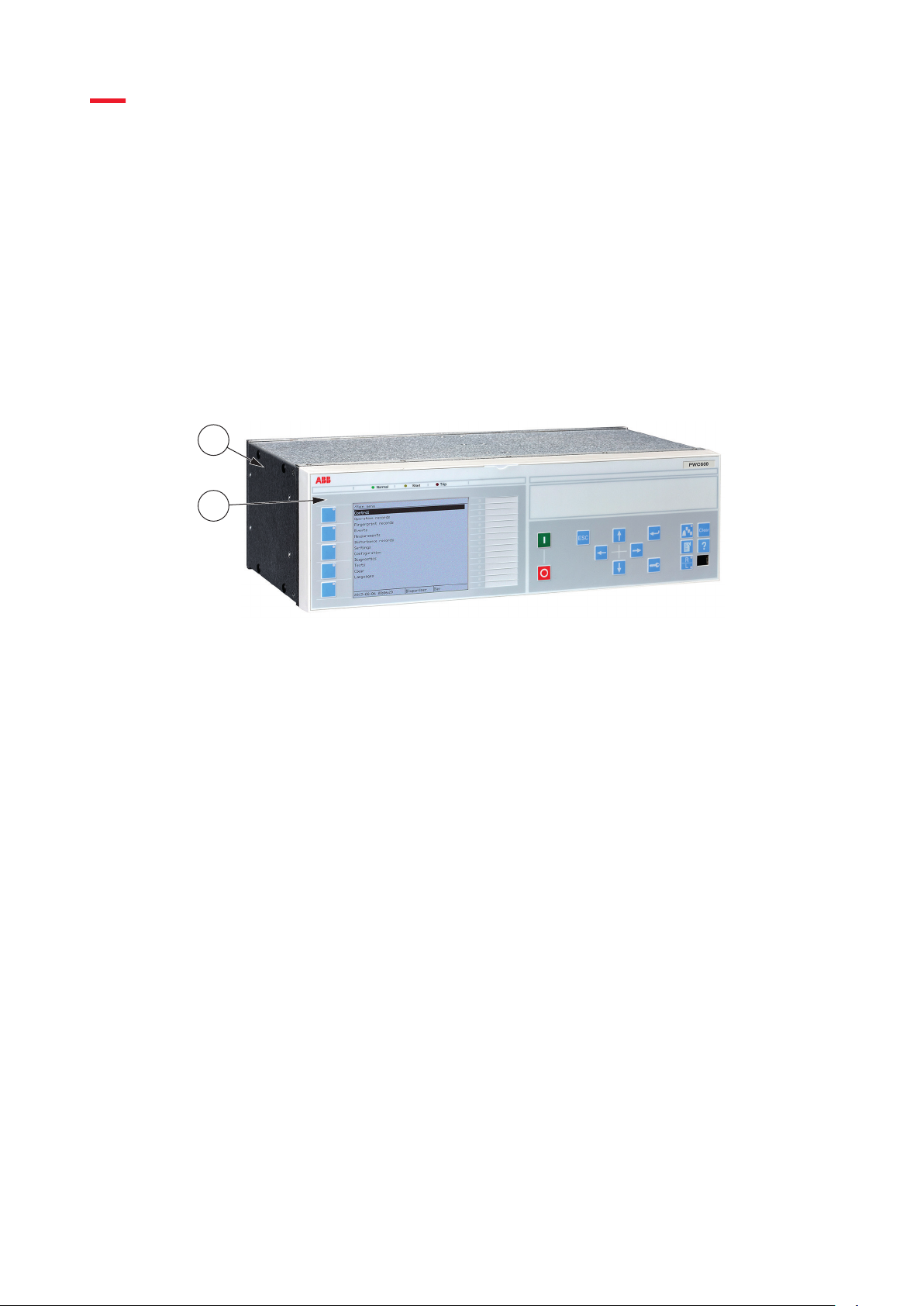
GUID-2D3D7A43-2A78-4159-8AB5-BA2CE19D03DD V1 EN-US
Figure 1: Switchsync PWC600 front view
GUID-B5FC3CED-4D7B-4F92-BA26-A9FAD91B0DDB v3
GUID-5E5B3CA8-3EC7-4C6B-87C2-4D76FEF5B56A v3
1 Enlosure
2 Local HMI
A label with the IED ordering number and serial number is attached to the local HMI.
17
User manual
© Copyright 2020 ABB. All rights reserved
Page 24

1
4
5
6
7
2
3
Section 3 1MRK 511 463 A
Switchsync PWC600 overview
GUID-0E37AEC8-5216-40B9-8046-7D390EE9A3C3 V1 EN-US
Figure 2: Switchsync PWC600 rear panel with hardware modules
1 PSM02/PSM03: Power supply module with options for 48...125 VDC or 110...250 VDC
2 TRM01: Instrument transformer module with 4 current and 6 voltage inputs
3 COM03 + CPU02: Communication and high performance processing module
4 and 5 Not used, slots are empty in Switchsync PWC600
6 BIO01: Binary input/output module
7 PIO01: Precision binary input/output module with event time resolution of 100 µs
For more information on connections, see Section 7.1.
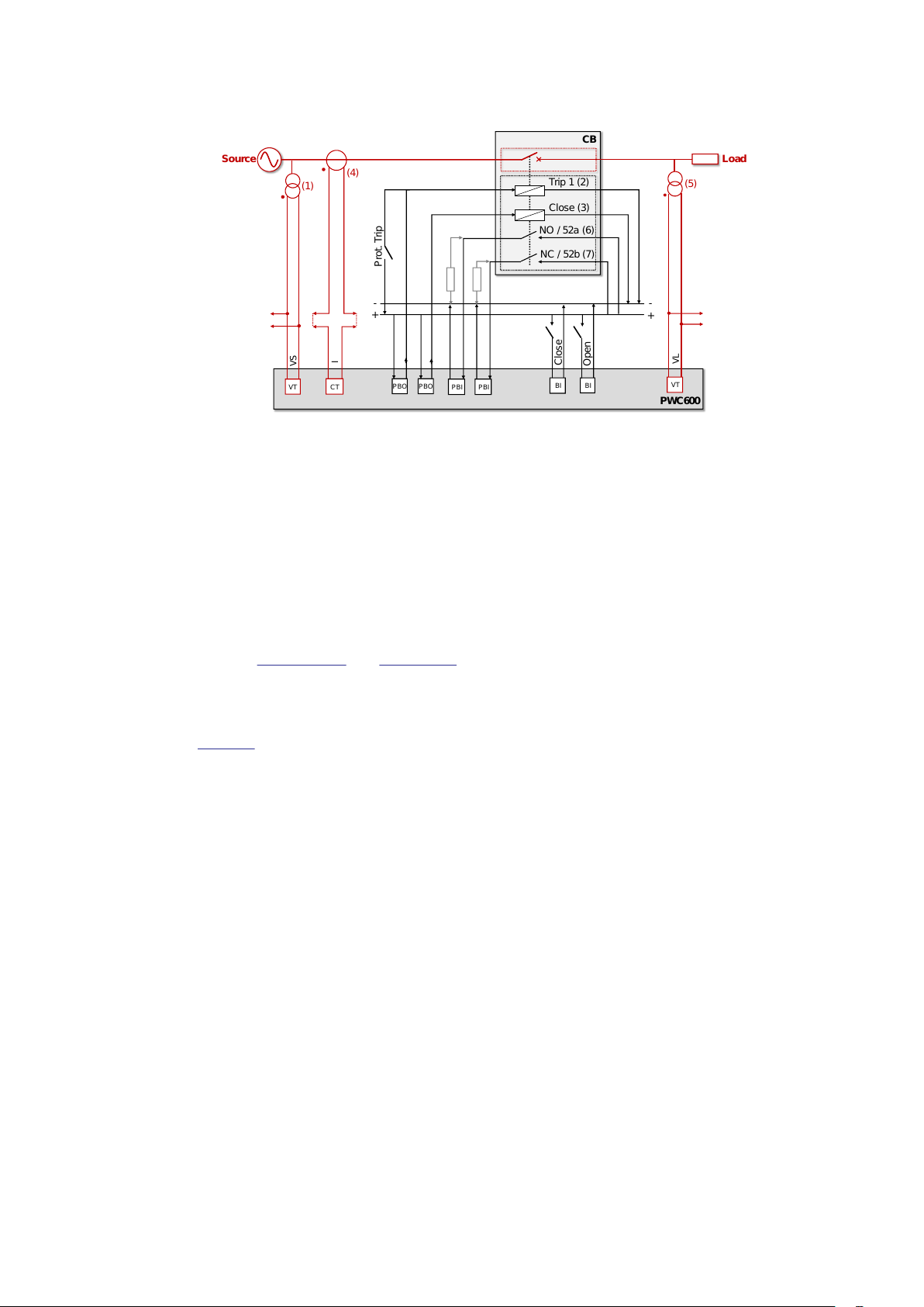
3.3 Functioning principle
The connection of PWC600 in a power system and its high-level functioning principle can be
understood from
optimal controlled switching instants for each phase from a primary reference signal. In most
cases, the reference is taken from a source side voltage transformer (1). The evaluation
considers the design and connection configuration of the load as well as the dielectric and
mechanical characteristics of the circuit breaker. Consequently, it issues a synchronized
opening or closing command to the respective operating coil (2 or 3) of each circuit breaker
pole.
Figure 3. Upon receiving an Open or Close command, PWC600 evaluates the
GUID-443A69F3-F594-406C-A808-ED266F45BA41 v1
18
© Copyright 2020 ABB. All rights reserved
User manual
Page 25
PWC600
Load
Source
I
CT
VL
VT
CB
-
-
Trip 1 (2)
Close (3)
Close
+
Open
BI
BI
+
Prot. Trip
VS
VT
PBO
PBI
PBO
PBI
NO / 52a (6)
NC / 52b (7)
(1)
(4)
(5)
1MRK 511 463 A Section 3
IEC19001157 V1 EN-US
Switchsync PWC600 overview
Figure 3: Overview of PWC600 integration in a power system
PWC600 also monitors the electrical and mechanical health of the circuit breaker as well as the
performance of controlled switching during the previous operation. This information is
obtained by detection the instants of inception or interruption of the primary feedback signal,
which can be load current (4) or load side voltage (5). If no suitable primary feedback signals
are available, monitoring is based on the changeover instants of CB auxiliary contacts 52a/NO
(6) and 52b/NC (7). From the available feedback signals, PWC600 calculates the target error
(difference between expected switching time and actual switching time from last operation)
and applies a timing correction in the next operation. This process is known as “adaptive
correction”.
Refer to
Section 4.4.2 and Section 4.5 for more details on adaptation and monitoring.
PWC600 also has a facility for measuring CB operating times during pre-commissioning
through temporarily connecting to the primary contacts of individual circuit breaker poles.
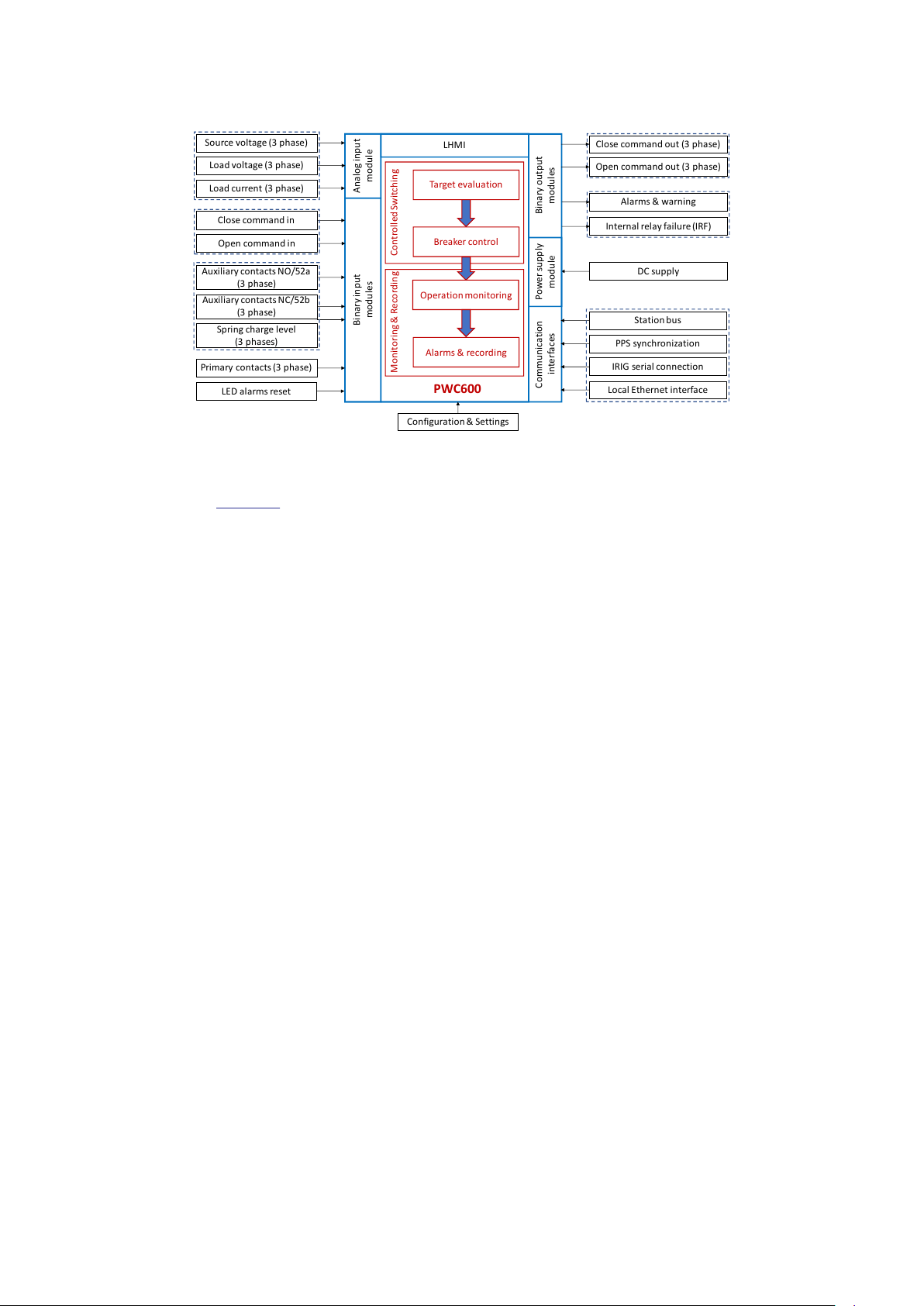
Figure 4 shows a block diagram of the interfaces to PWC600. The source side voltage, load
side voltage and load current are connected to the Analog input module (or alternatively
received on an IEC 61850-9-2(LE) compliant process bus). Incoming Open or Close commands
and output commands to the circuit breaker coils are connected to the binary input & output
modules. Also, the pole-wise auxiliary contacts and spring charge level (applicable for specific
drive designs) indicators are connected to binary input module. The power supply to the
PWC600 is provided through Power supply module. Alarms related to the health of the circuit
breaker as well as the performance of controlled switching operations can be generated by
relay contacts on the Binary output modules. The PWC600 IED continuously monitors itself
and in event of any internal failure, generates Internal relay failure (IRF) alarm. The user may
interact with PWC600 through the local user interface (LHMI) or through a web interface
(WHMI). Like for all ABB Relion IEDs, settings and configuration of PWC600 are prepared in
PCM600 tool.
User manual
19
© Copyright 2020 ABB. All rights reserved
Page 26
Analog input
module
Binary input
modules
Binary output
modules
Communication
interfaces
LED alarms reset
Source voltage (3 phase)
Load voltage (3 phase)
Load current (3 phase)
Close command in
Open command in
Auxiliary contacts NC/52b
(3 phase)
Spring charge level
(3 phases)
Auxiliary contacts NO/52a
(3 phase)
Primary contacts (3 phase)
Local Ethernet interface
Station bus
PPS synchronization
IRIG serial connection
DC supply
Power supply
module
Close command out (3 phase)
Open command out (3 phase)
Alarms & warning
Internal relay failure (IRF)
Target evaluation
Breaker control
Operation monitoring
Alarms & recording
Controlled SwitchingMonitoring & Recording
LHMI
PWC600
Configuration & Settings
Section 3 1MRK 511 463 A
Switchsync PWC600 overview
IEC19001158 V1 EN-US
Figure 4: External interfaces of PWC600 device
Refer Section 7 for more details on hardware interfaces of PWC600.
3.4 Application overview
Controlled switching, provided by Switchsync PWC600, is used for minimizing harmful
electrical transients upon planned switching of loads such as capacitor banks, shunt reactors,
power transformers, and power cables. The method is also gaining acceptance for reenergizing of EHV transmission lines, and replacing traditional pre-insertion resistors.
3.4.1 Common applications
The most common applications of controlled switching are listed below. Note that PWC600 is
intended only for intentional switching operations, not for protection trips.
Shunt capacitor banks
Basic aim is to control energization to minimize the voltage transients as well as inrush
currents. To improve interrupting performance, controlled opening can also be utilized.
Shunt reactors
Basic aim is to control de-energization to ensure reignition-free current interruption. In
addition, controlled closing also serves as a useful method for minimizing inrush currents.
D0E1353T201305141628 v2
GUID-AFC0A8F0-28AC-4E13-8513-78FF52B53283 v3
20
Power transformers
Basic aim is to control energization to minimize inrush currents. This is enabled by controlled
de-energization, to set a repeatable residual flux pattern, which is taken into account for the
subsequent energization.
Unloaded transmission lines and power cables
Basic aim is to control energization to minimize overvoltage transients and to prevent missing
current zeroes on fully compensated cables. To improve interrupting performance, controlled
opening can also be utilized.
© Copyright 2020 ABB. All rights reserved
User manual
Page 27

1MRK 511 463 A Section 3
Switchsync PWC600 overview
3.4.2 Variable applications
In a 1½ circuit breakers arrangement, the middle (tie) breaker is connected to a load on each
end. The same is applicable to every breaker in a ring layout. These two loads may be of the
same type but more often they are different.
The traditional approach to optimize controlled switching of both loads is to install two pointon-wave (POW) controllers for the breaker, together with a hardware logic for transferring
control to the appropriate POW controller. PWC600 1.1 and higher can accommodate these
functionalities in a single device through a feature called Setting Groups, which allows
automatic selection of different parameter sets based on external signals or conditions.
Variable applications, where setting groups are beneficial, include:
• For the tie breaker in 1½-CB or ring arrangements, select the appropriate reference source
and switching strategy depending on the status of adjacent switches and/or voltage
sources.
• In a double-busbar arrangement, select the appropriate busbar VT as reference, without
the need for external circuits for switching the VT signals.
• For power transformers, apply a fallback strategy for closing (assuming zero residual flux)
whenever the CB was opened not by PWC600.
• For loads with variable electrical configuration, e.g. switchable earthing of neutral point,
apply the optimal switching strategy in all cases.
• For any application, bypass the controlled switching functionality whenever an external or
internal binary signal is asserted.
• For FAT or similar situations, where the actual CB is switching low voltage, provide a set of
alternate CB settings (e.g. RDDS) that does not interfere with the original settings to be
applied in the high-voltage grid.
GUID-10FB53BF-40D7-45DA-A44C-9F4523D178F9 v1
3.5 User interfaces
The user can interact with Switchsync PWC600 in several ways.
• Local Human-Machine Interface (LHMI) on the front panel of the IED, featuring LCD screen,
pushbuttons and status LEDs
• Web interface via web browser
• Various tools in Protection and Control Manager PCM600, installed on a PC
3.6 Communication
The IED supports communication protocols IEC61850-8-1 and HTTPS over Ethernet, and IEC
61850-9-2(LE) over separate Ethernet process bus.
All operational information and controls are available through these protocols. However, some
communication functionality, for example, horizontal communication (GOOSE) between the
IEDs, is only enabled by the IEC 61850-8-1 communication protocol.
Waveform (disturbance) files are accessed using IEC 61850 or the Web interface. Disturbance
files are also available to any Ethernet based application in the standard COMTRADE format.
The IED can send binary signals to other IEDs (so called horizontal communication) using the
IEC 61850-8-1 GOOSE (Generic Object Oriented Substation Event) profile. Binary GOOSE
messaging can, for example, be employed for protection and interlocking-based protection
schemes. The IED meets the GOOSE performance requirements for tripping applications in
distribution substations, as defined by the IEC 61850 standard. Furthermore, the IED supports
GUID-DA31E614-A7EA-45DE-B496-B7AA88A308AC v3
D0E864T201305141540 v4
User manual
21
© Copyright 2020 ABB. All rights reserved
Page 28

Section 3 1MRK 511 463 A
Switchsync PWC600 overview
the sending and receiving of analog values using GOOSE messaging. Analog GOOSE
messaging enables fast transfer of analog measurement values over the station. The IED
interoperates with other IEC 61850 compliant IEDs, tools and systems and simultaneously
reports events to five different clients on the IEC 61850 station bus. IEC 61850-9-2(LE) is
supported for subscribing to current and voltage signals in digital sampled value format.
All communication connectors, except for the front port connector, are placed on the
integrated communication module. The IED is connected to Ethernet-based communication
systems via the RJ-45 connector (10/100BASE-TX) or the fibre-optic multimode LC connector
(100BASE-FX).
The IED supports the following time synchronization methods with a timestamping resolution
of 1 ms:
Ethernet communication based:
• SNTP (simple network time protocol)
With special time synchronization wiring:
• IRIG-B
• PPS (pulse per second)
PPS signals are used for IEC 61850-9-2(LE) process synchronisation with accuracy of 4 µs.
3.7 PCM600 tool
Protection and Control IED Manager PCM600 offers all the necessary functionality to work
throughout all stages of the IED life cycle.
• Planning
• Engineering
• Commissioning
• Operation and disturbance handling
• Functional analysis
When using PCM600 for writing to the IED, ensure that the LHMI or WHMI is not
in a menu position where settings can be changed. Only one active writing
transaction, from LHMI, WHMI, or PCM600, is allowed at a time.
With the individual tool components, you can perform different tasks and functions. PCM600
can operate with various topologies, depending on the customer needs.
For more information, see PCM600 documentation.
D0E808T201305141540 v3
3.7.1 Connectivity packages
A connectivity package is a software component that consists of executable code and data
which enable system tools to communicate with a specific type of IED. Connectivity packages
are used to create configuration structures in PCM600.
22
© Copyright 2020 ABB. All rights reserved
D0E811T201305141540 v2
User manual
Page 29

1MRK 511 463 A Section 3
Switchsync PWC600 overview
A connectivity package with its associated IED Module(s) includes all of the data which is used
to describe the IED. For example it contains a list of what parameters exist, which data format
is used, the units, the setting range, the access rights and visibility of the parameter. In
addition it contains code which allows software packages in PCM600 to properly
communicate with the IED. It also allows for localization of text even when it is read from the
IED in a standard format such as COMTRADE.
The connectivity package for PWC600 includes a product specific tool, Switchsync Setting
Tool (SST), for entering the required settings for the application. SST comes with a library of
ABB circuit breakers that can be used for controlled switching.
Update Manager is a tool that helps installing the appropriate connectivity package versions
for different system products and tools. Update Manager is included with PCM600.
3.8 Environmental aspects
3.8.1 Sustainable development
Sustainability has been taken into account from the beginning of the product design including
the pro-environmental manufacturing process, long life time, operation reliability and
disposing of the IED.
The choice of materials and the suppliers have been made according to the EU RoHS directive
(2002/95/EC). This directive limits the use of hazardous substances which are the following:
Table 1: Maximum concentration values by weight per homogeneous material
Substance Permitted maximum concentration
Lead - Pb 0.1%
Mercury - Hg 0.1%
Cadmium - Cd 0.01%
Hexavalent Chromium Cr (VI) 0.1%
Polybrominated biphenyls - PBB 0.1%
Polybrominated diphenyl ethers - PBDE 0.1%
Operational reliability and long life time have been assured with extensive testing during the
design and manufacturing processes. Moreover, long life time is supported by maintenance
and repair services as well as by the availability of spare parts.
D0E299T201305141600 v2
Design and manufacturing have been done under a certified environmental system. The
effectiveness of the environmental system is constantly evaluated by an external auditing
body. We follow environmental rules and regulations systematically to evaluate their effect on
our products and processes.
3.8.2 Disposing of the IED
Definitions and regulations of hazardous materials are country-specific and change when the
knowledge of materials increases. The materials used in this product are typical for electric
and electronic devices.
All parts used in this product are recyclable. When disposing of an IED or its parts contact a
local waste handler who is authorized and specialized in disposing electronic waste. These
handlers can sort the material by using dedicated sorting processes and dispose of the
product according to the local requirements.
User manual
© Copyright 2020 ABB. All rights reserved
D0E291T201305141600 v1
23
Page 30

Section 3 1MRK 511 463 A
Switchsync PWC600 overview
D0E305T201305141600 v1
Table 2: Materials of the IED parts
IED Parts Material
Unit Metallic plates, parts and screws Steel
Plastic parts
PC1), LCP
2)
LHMI display module Various
Package Box Cardboard
Attached material Manuals Paper
1) Polycarbonate
2) Liquid crystal polymer
24
User manual
© Copyright 2020 ABB. All rights reserved
Page 31

1MRK 511 463 A Section 4
Application
Section 4 Application
4.1 Introduction
Switchsync PWC600 is a point-on-wave controller, which is used to reduce electrical stresses
imposed on the circuit breaker as well as on the switched load during energization and deenergization operations. Switchsync PWC600 can be used for switching of all major load
applications including reactors, capacitor banks, cables, transformers and transmission lines
with various design and connection configurations. Circuit breaker closing and opening
commands that are not time critical are routed through Switchsync PWC600. The device (IED)
then issues individual commands to the circuit breaker poles depending on the load to be
switched, considering its connection and design configuration.
Recommended switching targets for common load types are programmed into the software
tools. From release 1.1.0 on, PWC600 is able to dynamically select one out of several controlled
switching scenarios, which is relevant, for example, for the middle (tie) breaker in a 1½ CB
arrangement.
After completion of a controlled switching operation, Switchsync PWC600 compares the
actual with the target switching instants. The results are used to optimize the estimated
operating times of the circuit breaker in the next operation. This process is known as
“adaptive correction”; it compensates for systematic changes in the circuit breaker’s
operation characteristics.
Deterministic changes in operating times due to internal or external parameters, such as
auxiliary voltage, idle time, ambient temperature, drive energy, can also be compensated using
individual compensation curves. Respective sensor signals are either connected to the IED
directly, or they can be received from remote sources via IEC 61850 analog GOOSE messages.
GUID-9EF14101-C2F3-4722-BF9F-A12644F91211 v2
Switchsync PWC600 is capable of calculating the expected remaining life of the circuit breaker
in terms of number of operations and electrical interrupter wear (ablation of arcing contacts,
erosion of nozzles). This is based on interrupted primary current and status signals of CB
auxiliary contacts.
On every supervised signal, Switchsync PWC600 can generate warnings and alarms when
crossing assigned limits. Such conditions can be indicated visually by LEDs on the LHMI,
electrically by alarm contacts on the IED, or remotely via its Ethernet communication
interfaces. Each supervision alarm can be individually enabled or disabled.
4.2 Load applications
Switchsync PWC600 is designed for point-on-wave switching (also known as controlled
switching) of capacitor banks, reactors, transformers, transmission lines, and power cables.
For each type of equipment and its design and connection configuration, the Switchsync
Setting Tool (SST) proposes controlled switching strategies based on CIGRE
recommendations. These switching strategies can be directly adopted by the user or modified
as needed. This provides full flexibility in accommodating load applications other than the predefined ones.
The following load applications are included in PWC600 along with recommended switching
strategies. Refer
Section 5.1 for more details on individual applications.
GUID-A3C989DF-31D3-4A17-B39B-55E2EC9F455B v1
User manual
25
© Copyright 2020 ABB. All rights reserved
Page 32

Section 4 1MRK 511 463 A
Application
4.2.1 Capacitor banks
Non-ideal energization of a capacitor bank may result in high transient inrush currents and, in
turn, high switching over-voltages. To minimize the inrush currents, energization shall be
performed near gap voltage zero of each pole of the circuit breaker connected to the capacitor
bank. In this regard, the connection configuration of the capacitor bank shall be considered for
deciding the optimum switching targets for individual poles of the circuit breaker.
Controlled de-energization is typically not needed, given that most modern CBs show a very
low probability of re-strikes; however, in some cases, an increased safety against re-strikes
may be preferred. Controlled opening targets are set to ensure sufficient arcing time such that
an adequate gap is achieved between contacts at the time of arc extinction. The time between
arcing contact separation until natural current zero where arc is expected to be quenched is
known as “arcing time”. Consequently, arcing times shall be determined considering the
expected natural current zero across individual poles of the circuit breaker based on the
connection configuration of the capacitor bank.
4.2.2 Shunt reactors
When de-energizing a reactor, interaction between the reactor's inductance and stray
capacitances will cause oscillating voltage transients with frequency in the range of kHz.
Generally, for latest generation of CBs, the current is interrupted in the in vicinity of natural
current zero for individual poles with very low value of chopping currents. Consequently, the
voltage transient across the breaker (TRV) may not have too high magnitude, but will have a
very short rise time in range of a millisecond. This can lead to breakdown of the dielectric
withstand of the contact gap and hence, reappearance of the current through arcing. This
phenomenon is known as a re-ignition and is not desirable because it can be harmful to both
shunt reactor and circuit breaker. Controlled opening is used to reduce the probability of reignitions by ensuring sufficient gap between arcing contacts at time of natural current zero,
where arc is expected to be quenched. The needed arcing time shall be evaluated considering
the last half-cycle length (which may be extended or shortened due to interaction between
phases) and probable over-voltage across the contact gap for each CB pole post the
successful interruption.
GUID-B74BC808-1076-41B2-9FF3-813908409C08 v1
GUID-08C3C3E9-EEC5-4D7C-BED4-0E96FE9B660C v1
Controlled energization of reactors may be implemented to reduce the asymmetry in charging
current due to initial DC component. It is worth noting that reactor cores do not typically
saturate and hence, the charging current will have sinusoidal waveshape (power frequency
only) with exponentially decaying DC component. The energization target is gap voltage peak
for individual pole of the CB.
Certain magnetic reactor designs or electrical connection configurations will
create inter-phase coupling effects upon switching. These include 3-limb core
design, which causes magnetic coupling between phases, and Y (ungrounded)
or delta connection schemes. The switching targets for individual poles of CB
should be evaluated considering these effects.
4.2.2.1 Re-ignition free window
Adequate arcing times shall be ensured to minimize the probability of re-ignitions. The value
of minimum arcing time derived from standardized reactor switching duty type test as
specified in IEC 62271-110 serves as the base of this evaluation. It is worth noting that, for
certain reactor configurations, the probable over-voltages post successful interruption and
last loop length may be different for individual CB poles based on the rating, design and
connection configuration of the reactor. Therefore,the optimal arcing times for controlled
opening may also differ between phases.
GUID-F1229BC6-EF2A-432A-B7CF-0255568EA3AE v1
26
User manual
© Copyright 2020 ABB. All rights reserved
Page 33

1MRK 511 463 A Section 4
Application
For controlled de-energization of a non-coupled YN-connected reactor, the initial target arcing
times for each CB pole are derived from the concept of "re-ignition free window", as shown in
Figure 5.
IEC19000959 V1 EN-US
Figure 5: Re-ignition free window for a non-coupled grounded reactor
Whenever the rising dielectric strength of the opening contact gap intersects the TRV, the
interrupter will re-ignite. This is usually the case for short arcing times. Hence, the arcing time
should not be lower than the minimum arcing time for re-ignition free interruption.
Figure 5
shows that the re-ignition free window of arcing times ranges from minimum arcing time, as
obtained from type testing, to the length of the last half cycle. To cater for variations in the
transient recovery voltage (TRV) due to rating of the reactor, mechanical & dielectric
characteristics of the CB and site conditions, the center of the re-ignition free window is
chosen as initial target arcing time for controlled opening.
As mentioned above, the length of last half cycle and the probable overvoltage post current
interruption depend upon rating, design, and connection configuration of the reactor.
Therefore, the initial target arcing time shall be evaluated for individual phases considering
these parameters. In this regard, the minimum arcing times are re-evaluated based on gap
voltage factors observed across individual interrupting poles for reactors with non-solidly
grounded systems. Consequently, the re-ignition free window and initial arcing times are
derived for individual circuit breaker poles. As the re-evaluation is based on linear
approximation, the minimum arcing time is always taken as lower limit for the re-evaluated
initial arcing time.
Initial arcing time values are provided as guidance as they are based on circuit
breaker characteristics and standard IEC applications, and may require further
adjustment depending on system specific considerations. As an example, for
reactors with very low nominal currents, the TRV may become higher than what
is specified in standard testing, and hence, may require longer target arcing
time. Please contact the circuit breaker factory for guidance.
4.2.3 Power transformers
During no-load energization of a transformer, controlled switching is used for reducing inrush
currents and, consequently, voltage distortion in the power system. For a weak grid, this
distortion can lead to considerable voltage dip. If the transformer is directly connected to a
long transmission line, it may create temporary overvoltage due to resonance of the line
User manual
© Copyright 2020 ABB. All rights reserved
GUID-6A686F06-C69A-422A-911D-089B6D356947 v1
27
Page 34

Section 4 1MRK 511 463 A
Application
capacitance with the transformer inductance. This can even lead to nuisance tripping of other
equipment connected on the same grid.
The latest generation of power transformers exhibits very low levels of no-load losses (in
range of 0.5-1% of the full load current). To achieve the same with optimum design,
magnetizing curve of transformers are designed with high operating flux densities with
saturation point just above the rated voltage of the transformer. This may lead to very steep
rise in magnetizing inrush current for a very small level of asymmetry in the operating flux. In
addition, the interphase coupling effects either because of electrical coupling due to at least
one delta connected winding or due to magnetically coupled phases, will result into interdependency between resultant fluxes linking with individual phase windings. Therefore,
asymmetry in resultant flux of one phase will impact the resultant flux linkage and hence,
inrush current in other windings. In this context, the fluxes linking with individual phases are
termed as “dynamic fluxes”.
It can be well appreciated that achieving symmetrical flux on energization requires
consideration of residual fluxes in the core observed during the previous de-energization,
effect of interphase dependency (dynamic fluxes) based on winding configurations (vector
group), and core design type (3 limb, 4/5 limb or single-phase bank) of the transformer.
Consequently, the switching strategy aims at energizing the individual poles on the reference
voltage waveform in such a way that the resultant dynamic fluxes will be symmetric. To
mitigate magnetic inrush current, no-load energization of a transformer should be performed
at a phase angle where the source side flux will be equal to transformer side flux. This will
create symmetric resultant flux in each limb, avoiding core saturation and resulting in
minimized magnetizing current. The information required on residual fluxes is derived by
controlled opening as a support for the subsequent controlled closing. The purpose of
controlled opening is to set a repeatable pattern of residual fluxes. The subsequent closing for
individual poles is targeted in such a way that the resultant flux will have minimum level of
asymmetry. Refer
Section 5.1.6 for proposed switching strategies for controlled switching of
transformers with different design and connection configurations.
4.2.4 Discharged transmission lines and cables
For transmission lines and power cables, controlled energization is used to minimize the
switching overvoltage on the line. To achieve this, controlled energization is targeted for gap
voltage zero for individual poles of the circuit breaker.
Often, long cables or lines are compensated with shunt reactors at one or two ends to
minimize reactive power pull during off-load condition. In such condition, energization targets
shall be checked against missing zero phenomenon, which carries a risk of circuit breaker
failure in case of protection trip during energization of the cable.
Like capacitor bank switching, controlled opening is typically not needed for cables and
transmission lines. Nevertheless, controlled de-energization can be used for ensuring re- strike
free operation of the circuit breaker.
4.3 Switching targets
On arrival of a switching command, the PWC600 IED calculates the optimal switching target
phase angles with respect to the reference voltage or reference current signals. The
calculations are based on the load to be switched, its connection and design configuration,
and the switching duty considering operating time variations and external parameter
variations.
GUID-FE8A6406-D763-476F-9606-0BA1A2795AC4 v1
GUID-6ED5BDE0-7BE7-4557-8891-B9D5F7406DE5 v2
28
User manual
© Copyright 2020 ABB. All rights reserved
Page 35

1MRK 511 463 A Section 4
Application
4.3.1 Target reference
Controlled switching targets in Switchsync PWC600 are defined with respect to a reference
signal.
• For load energization (controlled CB closing), primary voltage is always used as reference.
Voltage measurement may be single-phase or three-phase, for phase-to-ground or phaseto-phase voltage.
• For load de-energization (controlled CB opening), either the primary source voltage (same
as for closing operations) or the load current may be used as reference. Current
measurement must be taken from all three phases, and the CT secondary current should
not be lower than 50 mA.
Reference signals can be provided by conventional VTs/CTs, or from IEC 61850-9-2(LE)
compliant NCITs. Analog signals are sampled at a rate of 80 samples per power cycle, i.e.
sampling frequency of 4000 S/s at 50 Hz or 4800 S/s at 60 Hz. This sampling frequency
cannot be changed.
The selected reference signal can be used only when its amplitude is sufficiently high. For
signal levels below the "dead value" threshold, the IED will declare missing reference signal. If it
receives a controlled switching command in this condition it will fall back to a user-defined
contingency action of either unsynchronized switching (bypass) or blocking the CB operation.
4.3.2 Target definition
GUID-3D4FE7F8-0669-4A64-9899-8C9FCC413313 v3
GUID-6EAEDBE1-3ABF-4625-B510-42D8A7226D73 v1
With the reference signal selected, the individual switching targets are specified as phase
angles of the intended electrical switching instants, relative to a positive-going zero crossing
in the reference phase. The phase that should be switched first is called "lead phase" (some
applications require two lead phases to operate at the same time).
In PWC600 1.1, the reference phase is always L1 regardless which VT phases are connected to
the IED. Conversely, the lead phase can be selected arbitrarily according to the application
requirements.
For common controlled switching applications, the optimal switching targets are predefined
in Switchsync Setting Tool (SST), considering L1 as the lead phase. These should give good
results in most use cases. The user just needs to specify the type of load, its electrical
connections (vector group) and possibly few other design or application parameters. The tool
chooses the recommended controlled switching strategies from its built-in database and
presents them as default values. The user may directly adopt the proposed switching targets,
or adapt them to any special targeting requirements in the application. Details on specifying
controlled switching strategies in PWC600 are given in the following subsections.
4.3.2.1 Controlled energization targets
The making target for the L1 pole is specified as phase angle relative to a positive-going
voltage zero of the L1 phase-ground voltage, regardless which VT phases are connected to the
IED. For L2 and L3, the making targets are specified as phase angles relative to the L1 target.
As an example, the intended controlled closing strategy for a non-coupled grounded reactor is
to energize each phase at its phase-to-ground voltage peak. With L1 as lead phase, this will
give L1 making target as 90°, L3 making target at 60° after L1, and L2 target at 120° after L1.
Figure 6 shows the way targets are defined in SST based on selected application by the user.
The IED will further optimize and convert these electrical into mechanical target points (based
on circuit breaker characteristics) and further into release instants (based on mechanical CB
properties) for each breaker pole without further user input.
GUID-14FA53E2-628F-4A22-BD43-8E7E35259910 v1
User manual
29
© Copyright 2020 ABB. All rights reserved
Page 36

Current L1 Current L2 Current L3
Source voltage L1 Source voltage L2 Source voltage L3
Target L1 in SST Target L2 in SST Target L3 in SST
Target current making angle L1 Target current making angle L2 Target current making angle L3
Section 4 1MRK 511 463 A
Application
The optimized electrical target points for individual phases are presented in the operation log
as “Target current making angle”. Contrary to the definition above, though, each target
making angle stored in operation log is specified relative to the preceding positive-going
voltage zero crossing in the same phase (e.g. the L2 target making angle is given relative to a
L2 voltage zero). This is shown in
Figure 6. For more details on operation evaluation, refer
Section 4.5. For this example, considering an “ideal” circuit breaker, for which the impact of
circuit breaker characteristics (RDDS and scatter) can be neglected, the pre-defined targets to
appear in SST and in the operation log are shown in
Table 3.
IEC19000960 V1 EN-US
Figure 6: Target definition for controlled energization of non-coupled reactor
Table 3: Targets in SST and operation log for energization of a non-coupled grounded reactor
Making targets L1 (lead phase) L2 L3
Defined in SST 90° 120° 60°
Recorded in operation
log
90° 90° 270°
4.3.2.2 Controlled de-energization targets
The targets for controlled de-energization are specified in two parts for each phase:
• Expected angle of current interruption, which usually occurs at a natural current zero.
Elongation or shortening of the last current half cycle before interruption, due to electrical
or magnetic coupling between phases, needs to be taken into account.
• Target arcing time for reliable current interruption. This will give the target instant of CB
contact separation.
The current interruption target for phase L1 is specified as phase angle relative to a positivegoing zero crossing of either source voltage or breaker current in that phase. The interruption
targets in L2 and L3 are specified relative to the L1 target.
GUID-B0416338-6B6A-49AB-BC4D-C0D39529305B v1
As an example, the L1 current interruption target for a non-coupled grounded reactor with L1
as lead phase will be 270° with its source voltage as reference, or 180° with its current as
reference. For the second interrupting phase L3, it will be being 60° later than L1, and for the
last interrupting phase L2 it will be 120° later than L1. The arcing times for all three phases will
be identical (assumed to be 7.5 ms in this example) for a non-coupled grounded reactor.
7 shows the way targets are defined in SST based on selected application by the user. The IED
will phase wise convert the current interruption instances into output commands based on
defined arcing times for individual phases.
SST for both source voltage and current as reference.
30
© Copyright 2020 ABB. All rights reserved
Figure
Table 4 shows the pre-defined targets to appear in
User manual
Page 37

Current L1 Current L2 Current L3
Arcing time L1 Arcing time L2 Arcing time L3
Source voltage L1 Source voltage L2 Source voltage L3
Contact separation target L1 Contact separation target L2 Contact separation target L3
Current interruption target L1 Current interruption target L2 Current interruption target L3
1MRK 511 463 A Section 4
IEC19000961 V1 EN-US
Application
Figure 7: Target definition for controlled de-energization of non-coupled reactor,
source voltage reference
IEC19000779 V1 EN-US
Figure 8: Target definition for controlled de-energization of non-coupled reactor,
current reference
Table 4: Targets in SST for de-energization of a non-coupled grounded reactor
Reference
signal
Source
voltage
Load current 180° 120° 60°
The predefined switching targets are optimized for single-pole operated (SPO) circuit
breakers, which are considered best suitable for controlled switching. However, it is possible
to perform controlled switching for three-pole-operated (TPO) circuit breakers with ganged
operation or mechanical staggering. Refer
Current interruption targets
Arcing time (ms)
at natural current zero
L1 (lead
phase)
L2 L3 L1 (lead
phase)
L2 L3
270° 120° 60° 7.5 7.5 7.5
SST by default suggests L1 as lead phase for the different applications. Specify
a different lead phase by entering a negative value for the L2 and/or L3
interruption target. Refer Section 5.2.3 for more details.
Section 5.2.2 for more details.
User manual
© Copyright 2020 ABB. All rights reserved
31
Page 38

Section 4 1MRK 511 463 A
Application
4.3.3 Circuit breaker properties
Knowledge of key parameters of the circuit breaker is essential for successful controlled
switching. These key parameters are usually separate for Close and Open operations.
• Mechanical behavior under nominal conditions (timing, accuracy)
• Dielectric properties (RDDS, re-ignition free window)
• Impact of external influences, such as DC control voltage or temperature, on operating
times (compensation curves)
• Permitted limits on deviation from default values
• etc.
Some of these parameters are defined by the circuit breaker design; these can be provided in
advance. Others are specific to each pole and are ideally obtained on site during (or prior to)
commissioning.
Switchsync Setting Tool (SST) provides easy access to all relevant parameters. The installation
package of the Switchsync PWC600 Connectivity Package also includes a library of ABB circuit
breaker models, containing design-related parameters. In case the actual circuit breaker model
is not included, the user may define a new “custom” circuit breaker type by modifying data
from the library, or create a new circuit breaker type altogether.
For acquisition of pole-specific parameters prior to live switching, Switchsync PWC600
provides a “CB timing test mode”. With the main contacts temporarily connected to dedicated
inputs, offline switching operations are controlled and evaluated by the IED. The properties
thus learned are used in regular operations.
GUID-57DE7EE4-C3A9-4447-870E-A39470A9612F v2
4.4 Optimization of accuracy
The operating times (switching times) of the circuit breaker may change with certain
parameters, such as time (age), temperature, idle time since the last operation, and DC control
voltage. To optimize the controlled switching performance against such changes, Switchsync
PWC600 provides two features, parameter compensation and adaptive correction. Based on
these features, the release instants of the circuit breaker are adjusted for optimal targeting
during controlled switching operations.
4.4.1 Parameter compensation
The Switchsync PWC600 IED has the facility to compensate for the influences of external and
internal parameters, namely, DC control voltage, idle time, temperature, drive pressure, spring
charge, and an additional user-defined parameter. For each of these, it applies individual
parameter compensation curves consisting of parametric variation vs. required operating time
correction. Separate curves are provided for Close and Open operations. The individual
compensation values are added up to yield a total compensation value for each CB pole.
The library of ABB circuit breakers includes compensation curves for each CB type. During
engineering in Switchsync Setting Tool, the user only needs to specify which sensors are
connected to the IED. Accordingly, the compensation functions are activated. It is possible to
enable, disable or modify individual compensation curves manually. Respective sensor signals
are either connected to the IED directly, or are received from external acquisition devices (such
as ABB RIO600) via IEC 61850 analog GOOSE messages. See
GUID-B20C6CAD-C82A-40DC-90BC-4BE38AC20621 v2
GUID-65F87814-1CA3-46DC-94B8-AC8FBD53595B v2
Table 5 below.
32
User manual
© Copyright 2020 ABB. All rights reserved
Page 39

3( ) 3( )new old
TT
= +
1MRK 511 463 A Section 4
Table 5: Compensation facilities in pre-configuration
Parameter Sensor Qty. Inputs to IED
DC control
voltage
Idle time Internal calculation based on
Stored
energy in CB
drive
TemperatureTemperature sensor (e.g.
Drive
pressure
Additional
quantity
(userspecified)
Voltage sensor 1 DC supply on PSM module
status of current signal, load
voltage signal, and/or CB
auxiliary contacts
Set of 1 or 2 binary level
contacts
Pt100) connected to external
acquisition device
Pressure sensor connected
to external acquisition device
Sensor for additional
quantity, connected to
external acquisition device
3 CT or VT inputs on TRM module, current or
voltage samples via IEC 61850-9-2, or binary
inputs on PIO module
1 or 3 sets Binary inputs on BIO module
1 or 3 Analog GOOSE
1 or 3 Analog GOOSE
1 or 3 Analog GOOSE
Application
Compensation values are continuously updated. Thus, the actual compensation value is
available at the time when a controlled switching operation is executed. Furthermore, each
sensor signal is checked against supervision thresholds, and an alarm can be raised on
crossing a limit.
4.4.2 Adaptive correction
After completion of a controlled switching operation, Switchsync PWC600 acquires the
instants when the switching actually took place. For this purpose, it analyzes the primary
analog signals (load current, load voltage) and the timing of binary signals from auxiliary
contacts in the CB drive, as available. The instants of inception or interruption of the primary
signals are determined using adjustable detection thresholds, see
Recommendations on the selection of feedback signals are given in Section 4.5.4.
The actual switching instants are compared with the target instants; the difference is called
Target error. It is the basis for adaptive correction and other monitoring features.
4.4.2.1 Adaptive correction for closing
For closing operations, a fraction
to update the estimated CB operating time for the next controlled closing operation. This
process is known as “adaptive correction”; its purpose is to compensate systematic changes
in the circuit breaker’s operation characteristics over time.
β
(Beta factor) of the target error is used as correction value,
GUID-D28BECD1-2961-4CCF-8E91-AA5F407FC292 v3
Section 4.5.1.2.
GUID-A17C3FE5-0633-49C3-9792-01C708A26169 v1
User manual
PWC600 maintains internal adaptive correction values T3 for each breaker pole. After each
controlled closing operation, T3 is updated with the target error ε according to
IECEQUATION19015 V1 EN-US
© Copyright 2020 ABB. All rights reserved
(Equation 1)
33
Page 40

Section 4 1MRK 511 463 A
Application
Higher values of β will make the adaptive correction converge faster but may cause overshoot
in case of fluctuating target errors. Conversely, lower values of β will provide smooth approach
to the ideal target but will take longer to converge.
These calculations are done for each phase individually. Separate β factors are provided for
electrical and mechanical feedback; however, it is recommended to use adaptive correction
only on either electrical or mechanical feedback and set the other β factor to zero.
When using load current or load voltage for detecting the actual switching
instants, adaptive correction is limited to adjusting for target errors not
exceeding a quarter cycle. Hence, it is important to validate the actual
controlled switching performance from the waveform records during
commissioning. If high target errors are observed, the appropriate settings
must be adjusted for good initial target accuracy.
4.4.2.2 Adaptive correction for opening
For opening operations, detection of each restrike/ reignition in any phase will cause
increment in target arcing time by 1 ms for the respective phase for the next operations. The
number of allowed increments (re-strike/re-ignition corrections) can be configured as
disabled, 1 ms or 3 ms. If exceeding the number of allowed re-strike/re-ignition corrections, CB
operations will be blocked irrespective of the contingency mode set by the user.
The internal values for adaptive correction and operation logs are periodically
written to non-volatile memory to be preserved against power loss. To
maximize the life of the memory elements, the write interval has been defined
as 1 hour; this cannot be changed by the user. Therefore, to prevent loss of
data, the IED should not be powered off within 1 hour of the last switching
operation.
4.4.3 Overall optimization
4.4.3.1 Optimization of closing operations
For Close operations, the target instant TtC of mechanical contact touch in each phase is
internally calculated as follows.
GUID-3BB918FB-05AF-41B4-8884-EABADE657D6B v1
GUID-2492E4F0-DE4C-48DA-947B-E14BA039B0CA v4
GUID-8B32F5FC-B6F9-4FD1-A48E-D8F1480E4A66 v1
34
TtC = T0 + T1 + T2 + T3 + T
4
where
T0 = ideal making target
T1 = offset from ideal target, to cater for dielectric and mechanical scatter
T2 = total combined correction value from parameter compensations
T3 = total combined correction value for electrical and/or mechanical adaptation
T4 = expected pre-arcing time (time between current inception and mechanical contact touch)
To achieve best possible performance considering dielectric and mechanical scatter, the
difference in pre-strike voltage at both boundaries of the target making window shall be
minimized. Consequently, the final (strategic) making target is slightly shifted from the ideal
User manual
© Copyright 2020 ABB. All rights reserved
Page 41

Figure 8 section 3.4.3
Gap voltage Current Contact gap dielectric strength
Operating time scatter Contact gap dielectric scatter Overall scatter boundaries
Ideal target Strategic target Target making window
Strategic target normalization
Target making window
T1
T4
Ideal target for making: Peak of the gap voltageStrategic target for making: Slightly before gap voltage peak
Figure 9 section 3.4.3
Gap voltage Current Contact gap dielectric strength
Operating time scatter Contact gap dielectric scatter Overall scatter boundaries
Ideal target Strategic target Target making window
Strategic target normalization
Target making window
T1
T4
Ideal target for making:
Zero crossing of the gap voltage
Strategic target for making:
Slightly after gap voltage zero
1MRK 511 463 A Section 4
Application
target: forward for gap voltage zero target and back for gap voltage peak target. T1 and T
4
during controlled closing operation at voltage peak target and voltage zero target are
demonstrated in Figure 9 and Figure 10 respectively.
GUID-E4E3069B-823C-4726-81EF-9B3649482E0F V3 EN-US
Figure 9: Switching target optimization for controlled closing, voltage peak targeting
GUID-0C261925-4999-4EC1-9136-57C1B7E55323 V2 EN-US
Figure 10: Switching target optimization for controlled closing, voltage zero targeting
Whenever the making target is specified as 0° or 90°, PWC600 optimizes the actual target
instants as described above. For any other making target, no optimization is done but the
4.4.3.2 Optimization of opening operations
User manual
actual target instants are constrained to the range spanned by the strategic targets for 0° and
90°.
For controlled opening operations, the target instant TtO of mechanical contact separation is
calculated as:
TtO = T0 – T3 – T4 = T0 – T
5
© Copyright 2020 ABB. All rights reserved
GUID-57CB87EC-849A-4EE5-A9E1-4EBDC3A6B332 v1
35
Page 42

Source voltage Gap voltage Current Contact gap dielectric strength
Section 4 1MRK 511 463 A
Application
where
T0 = ideal interrupting target
T3 = adaptive correction value for target arcing time due to re-strike or re-ignition detection
T4 = initial target arcing time (time between mechanical contact separation and current
interruption)
T5= Extended arcing time due to adaptive correction
T3, T4 and T5 are shown in Figure 11, which depicts current interruption at reference voltage
peak.
GUID-B20044E3-0841-45A0-8140-522E955366F1 V2 EN-US
Figure 11: Optimization of contact separation target for controlled opening (source
voltage reference)
4.5 Monitoring and supervision
All signals acquired by the Switchsync PWC600 IED are primarily used for execution and
optimization of controlled switching operations. In addition, the same signals can be used for
monitoring and supervision of the circuit breaker’s switching performance and its aging (due
to number of operations or interrupter wear).
On receiving a switching command, the available compensation signals are evaluated for
compensation values. After issuing a switching command, the IED monitors the input signals
for status changes. The sequence of these events is evaluated to determine actual operating
times and further conditions such as re-ignitions/re-strikes. All these data are recorded in the
operation log.
The very first operation records (default: 20) are stored as “fingerprint records” in a separate
instance of the operation log for later reference.
Table 6 summarizes the potential use of external signals (if available).
GUID-27ABFF2E-40DA-449A-A997-BA4C950B49E8 v2
36
© Copyright 2020 ABB. All rights reserved
User manual
Page 43

1MRK 511 463 A Section 4
Application
Table 6: Circuit breaker monitoring features
Signals Controlled switching optimization Monitoring and supervision
Current throughCB• Adaptive correction of
electrical switching times
• Idle-time compensation of
mechanical switching times
• Electrical switching target errors
• Electrical making times and interrupting
times
• Re-ignition/re-strike
• Interrupter wear (contact ablation, nozzle
erosion)
• Circuit breaker status (open, closed)
• Idle time (time since last CB operation)
• Externally initiated switching operation
• CB operations count
Load voltage • Adaptive correction of
Auxiliary
contacts status
DC control
voltage
Temperature • Temperature compensation of
Drive pressure • Pressure compensation of
Spring charge • Spring charge compensation
Additional
quantity (user
defined)
Trip circuit
voltage
electrical switching times
• Idle-time compensation of
mechanical switching times
• Adaptive correction of
mechanical switching times
• Idle-time compensation of
mechanical switching times
• Voltage compensation of
mechanical switching times
mechanical switching times
mechanical switching times
of mechanical switching times
• Additional compensation of
mechanical switching times
-
• Electrical switching target errors
• Electrical making times and interrupting
times
• Circuit breaker status (open, closed)
• Idle time (time since last CB operation)
• Externally initiated switching operation
• CB operations count
• Mechanical switching target errors
• Mechanical closing times and opening times
• Initial delay time, moving time
• Idle time (time since last CB operation)
• Externally initiated switching operation
• CB operations count
• Limit supervision
• Limit supervision
• Limit supervision
• Limit supervision
• Limit supervision
• Trip circuit supervision
For estimating interrupter wear, it is recommended to use protection class CT
cores.
Various supervision alarms have been pre-defined to indicate if the associated parameter
crosses the limit. Each alarm can have two stages: warning and alarm, for which user can
define the limits, and which can be individually enabled or disabled.
4.5.1 Electrical operations monitoring
Following every controlled switching operation, certain parameters are extracted from the
recorded feedback signals, which can be selected as CB current or load voltage. They are
User manual
© Copyright 2020 ABB. All rights reserved
GUID-151481B3-1CEE-4B9C-AA78-C0129ABFFCA2 v3
37
Page 44

Section 4 1MRK 511 463 A
Application
summarized in Table 7. Close and Open commands refer to the control signals given to the
circuit breaker drive.
Table 7: Monitored electrical parameters
Parameter Definition Remarks
Circuit breaker status Current through CB, or load
Current making angle Phase angle of detected current
Electrical operating time (making
time, interrupting time)
Arcing time Time from estimated instant of
Electrical target error Difference between actual
Re-ignition/re-strike Re-occurrence of CB current
Interrupter wear Combined figure of contact
voltage, is above threshold
inception instant, relative to
positive-going reference voltage
zero crossing
Closing (current making): Time
from CB Close command to
current inception
Opening (current interruption):
Time from CB Open command to
final current interruption
mechanical separation of arcing
contacts to final current
interruption
(measured) electrical operating
time and predicted (target)
electrical operating time
detected after the expected
current interruption instant
erosion, nozzle ablation, and so
on, based on interrupted primary
current
For loads of type power
transformer, transmission line, or
power cable, the nominal load
current needs to be set to the
expected charging current under
no-load conditions.
Relevant for CB closing operations
only.
Obtained from CB current or load
voltage signals
Relevant only for CB opening
operations.
Every detected re-ignition/restrike increases a counter and
increases the target arcing time
(up to a set limit).
4.5.1.1 Circuit breaker electrical status
Switchsync PWC600 attempts to detect electrical status change of the circuit breaker (current
making or current interruption) from the primary current or load voltage signals. The
strategies employed vary by the set load type.
• For capacitor bank and shunt reactor type loads, it can be assumed that load current is
generally above dead-band value when energized.
• Power transformers exhibit very low magnetizing currents when energized. These currents
are usually too low for reliable electrical operation detection. Electrical status detection is
therefore based on load voltage only, if available. However, in case of electrical or
magnetic coupling, additional measures are needed for correct detection of the making
instants. Refer to
Electrical and magnetic coupling between phases can mislead the status
detection algorithm. Hence, it is recommended to connect auxiliary contacts to
the IED to allow mechanical status detection especially when load voltage is
not used to detect the electrical operations.
38
Section 5.2.5 for details.
© Copyright 2020 ABB. All rights reserved
GUID-6E5CBC2A-F24A-47E7-B61D-7358535E3EE9 v4
User manual
Page 45

1MRK 511 463 A Section 4
Application
In case of a weak source, switching operations may cause voltage interference
between phases for loads that are not solidly grounded. Therefore it is
recommended to use current as feedback signal except for transformer
application.
4.5.1.2 Detection of electrical switching instants
Detecting the precise instant of current making or current interruption is crucial to
maintaining optimal accuracy by adaptive correction, and for faithful reporting of the
controlled switching success. For detecting the actual instants when the selected electrical
feedback signal starts or stops, PWC600 checks the signal against two thresholds.
1. Coarse threshold: The percentage of base value of voltage or current (based on selected
feedback for monitoring and adaptation) to eliminate incorrect detection. This threshold
should be high enough for reliable discernment of the presence or absence of the feedback
signal even in the presence of noise, crosstalk, or inter-phase coupling effects.
2. Fine threshold: The percentage of base value of voltage or current (based on selected
feedback for monitoring and adaptation) at which making or interruption is to be detected.
This threshold should be low enough to achieve accurate inception or interruption instant
detection while eliminating the effect of noise.
Always the fine threshold setting should be lower than the coarse threshold
setting for both energization and de-energization operations.
Table 8 shows the proposed values of thresholds to be set in SST for different load
applications.
Table 8: Suggested coarse and fine threshold settings for various applications
Load Feedback signal Close Open
Coarse threshold Fine threshold Coarse threshold Fine threshold
Capacitor Current 10% 3% 20% 3%
Reactor Current 10% 3% 20% 3%
Transformer Load voltage 30% 20%
Transmission
line or cable
*
) not relevant as load voltage cannot be used for detecting interruption instants.
Load voltage 10% 3% 20% 10%
GUID-7008CCA4-9F5E-47CF-BA63-3B49FD6A26FE v1
20%*) 3%*)
User manual
Generally, the proposed values given in Table 8 provide good accuracy in
detection. In case of initially incorrect results the thresholds should be adjusted
to provide sufficient margin considering possible variations in noise level.
PWC600 further converts the detected instants of current making and current interruptions
into electrical operating times and actual switching angles. These values are recorded in the
operation log and used for further monitoring purposes as described above.
Making instant detection
During closing operation, the algorithm initially detects the point where the absolute value of
GUID-5F57FFCE-D63C-4E8B-9C24-7D88AA8C7F93 v1
the signal first rises above the coarse threshold. From there, it back-tracks the waveform till it
crosses the fine threshold. The earliest point where the signal crosses the fine threshold is
declared as the inception instant.
© Copyright 2020 ABB. All rights reserved
39
Page 46

Current
Detected making instant
Crossover of waveform for coarse threshold
Fine threshold
Coarse threshold
Actual current start instant
Noise
Current
Detected interruption instant
Crossover of waveform for coarse threshold
Fine threshold
Coarse threshold
Actual current interruption
Section 4 1MRK 511 463 A
Application
Figure 12 demonstrates the way fine and coarse threshold are set for correct detection of
making instant based on electrical current feedback. It can be observed that with proper
adjustment of these thresholds, current start with very low magnitude can be detected with
good accuracy. The error in detection is the time difference between the green and the red
points marked in the figure, which happens to be very small.
IEC19000962 V1 EN-US
Figure 12: Defining thresholds for making instant detection during energization
Interrupting instant detection
For load de-energization, current interruption in most cases occurs at a natural current zero.
GUID-90DFAF92-9E07-4B4A-9102-BBFC078BE608 v1
Thus, the actual instant of contact separation cannot be deduced from the primary voltage
and current signals. However, Switchsync PWC600 checks the current signals for signs of reignitions/re-strikes, in particular final current interruption occurring significantly later than
expected. Moreover, after actual current interruption, many times, noise having decaying DC
or L-C oscillatory nature is observed. This may lead to wrong re-ignition detection. To ensure
proper detection, coarse and fine threshold settings shall be adjusted as shown in
IEC19000963 V1 EN-US
Figure 13.
Figure 13: Defining thresholds for current interruption instant detection during de-
energization
During opening operation, the algorithm initially detects the point where the absolute value of
the signal last drops below the coarse threshold. From there, it forward-tracks the waveform
till it crosses the fine threshold. The instant of crossing the fine threshold is declared as the
interruption instant. As shown in
fairly low value to enable detection of re-ignitions of low current amplitude. Moreover, this
value should be set to provide sufficient margin against noise, decaying DC, or fast oscillatory
signals.
Figure 13, the coarse detection threshold should be set to a
4.5.1.3 Detection of re-ignitions/re-strikes
40
GUID-0E3DD850-E940-4FA6-9F05-58D61FA61B0B v1
During opening, the circuit breaker is usually expected to interrupt the primary current at its
natural zero. If current starts flowing again after that current zero, this is called a re-ignition
(for inductive loads) or re-strike (for capacitive loads). The steep voltage front of current
restart may damage the interrupter, hence it is desirable to avoid such events.
In every controlled opening operation, Switchsync PWC600 checks the electrical interrupting
time from the load current signal (when available). If final current interruption is observed
User manual
© Copyright 2020 ABB. All rights reserved
Page 47

Voltage
Current
time
Dielectricstrengthacross
breaker
TRV
time
TRV
Instantofcontact
separation
Initialcurrent
interruption
Re‐ignition
IEC19000918-1-en.vsdx
1MRK 511 463 A Section 4
Application
within 1/4 of the power cycle later than expected, this is interpreted as re-ignition as shown in
Figure 14.
IEC19000918 V1 EN-US
Figure 14: Re-ignition in an inductive load
On the other hand, if the current interrupt interrupts later than 1/4 of the power cycle than
expected, its considered as re-strike as shown in
Figure 15.
User manual
© Copyright 2020 ABB. All rights reserved
41
Page 48

Voltageacross
thebreaker
Capacitor
voltage
Source
voltage
Current
Vm
Vm
‐Vm
Vm
2Vm
time
time
time
‐4Vm
3Vm
‐5Vm
Instantofcontact
separation
Instantofcurrent
interruption
Dielectricstrength
acrossbreaker
Re‐strikes
IEC19000917-1-en.vsdx
Section 4 1MRK 511 463 A
Application
IEC19000917 V1 EN-US
4.5.1.4 Interrupter wear
Figure 15: Re-strike on a capacitive load
In new condition, a circuit breaker is rated for a certain number of mechanical operations, that
is, interrupting no or very low currents. It is also rated for a certain (low) number of operations
interrupting maximum fault current. Between these extremes, the interrupted current in every
Open operation causes some erosion of the contacts and ablation of the nozzles, until the CB
42
GUID-A553BE40-D5C1-4F8D-8A5D-B5E7A15D5E47 v3
User manual
© Copyright 2020 ABB. All rights reserved
Page 49

IntTh1 IntTh2
10
100
1000
10000
0 10 20 30 40 50 60 70
Number of switching operations
Interrupted current (kA)
1MRK 511 463 A Section 4
Application
loses its ability to reliably switch off currents. This interrupter wear characteristic is often
given in form of a curve.
GUID-3DCD06E6-F638-4749-BF54-34B54D94B140 V2 EN-US
Figure 16: Example of interrupter wear characteristic of a circuit breaker rated for 10000
mechanical operations (interrupting currents up to IntTh1 = 3000 A) or 20
interruptions of rated fault current IntTh2 = 63 kA
Switchsync PWC600 calculates interrupter wear as the equivalent number of mechanical
operations that the circuit breaker has lost after interrupting a specific current. This individual
value and the cumulated interrupter wear are recorded in the operation log. Upon reaching the
limits specific to each breaker type, a warning or alarm will be raised. The algorithm for
calculation of interrupter wear is explained in the Technical Manual.
It is recommended to contact ABB for obtaining the optimal coefficients for
interrupter wear of any circuit breaker type that is not included in the CB library
of SST.
4.5.2 Mechanical operations monitoring
Following every switching operation, certain parameters are calculated from recorded instants
of auxiliary contacts' changeover. They are summarized in Table 9, assuming both contact
types (52a/NO and 52b/NC) are connected to the Switchsync PWC600 IED. Close and Open
commands refer to the control signals given to the circuit breaker drive.
GUID-F94B9AFB-2C6E-46CD-BC21-D29F309AC847 v2
User manual
43
© Copyright 2020 ABB. All rights reserved
Page 50

time
travel
T
NC
T
NO
Section 4 1MRK 511 463 A
Application
Table 9: Monitored mechanical parameters
Parameter Definition Remarks
Initial delay time Closing: TNC = Time from Close
command to opening of 52b (NC)
contact
Opening: TNO = Time from Open
command to opening of 52a (NO)
contact
Moving time T
Mechanical operating time
(closing time, opening time)
Mechanical target error Difference between actual
Unstable operating times Fluctuation between several
NONC
Closing: TNO – TNC = Time from
opening of 52b (NC) to closing of
52a (NO) contact
Opening: TNC – TNO = Time from
opening of 52a (NO) to closing of
52b (NC) contact
Closing: T
command to estimated point of
contact touch
Opening: T
command to estimated point of
contact separation
(measured) mechanical operating
time and target mechanical
operating time
consecutive operating times
higher than threshold
= Time from Close
main
= Time from Open
main
Can be calculated only if
respective auxiliary contact
signals are available.
Can be calculated only if both
auxiliary contact signals are
available.
Linear estimation, based on initial
delay time and moving time.
Indication of unstable operating
times must be cleared manually.
Figure 17 shows a typical circuit breaker closing operation, to demonstrate the mechanical
monitoring parameters. The main portion of the linear travel curve (gray) is approximated by a
straight line (black) connecting the changeover points of the 52a (NO) and 52b (NC) auxiliary
contacts. The vertical axis marks the time when the closing command is given to the CB drive
(t=0).
GUID-54A36C70-49D1-40A3-AE26-A8C7A5B44E9E V2 EN-US
Figure 17: Definition of mechanical monitoring parameters for a CB Close operation.
Definition for Open operations is equivalent.
4.5.3 Recommended alarms
Table 10 shows the list of user settable alarms to be enabled for different applications. For the
alarms listed in the table, if any application is not mentioned, the respective alarm can be
disabled. User requirements take precedence.
44
© Copyright 2020 ABB. All rights reserved
GUID-BE55E502-CCD6-45DA-961B-F2B63A8EA79E v1
User manual
Page 51

1MRK 511 463 A Section 4
Application
Table 10: Recommended alarms to be enabled for various applications
Alarm list Application
Unsynchronized switching operation All
Actual switching instants, or CB operating time, out
of limit
Re-ignition/re-strike Reactor, capacitor, cable
Unstable circuit breaker operating characteristics Overhead transmission lines
Loss of reference signal All
All
The full list of possible alarms and other diagnostic indications is given in Section 16.1.
4.5.4 Selection of feedback signals
Table 11 shows the list of required feedback signals for various load applications. The
mentioned signals are applicable for any design and connection configuration of the specified
load. For any type of load, the source voltage (1 or 3 phases) must be used as reference for
controlled closing operations.
Table 11: Recommended list of reference and feedback signals for various applications
Load Purpose Required signals Remark
Capacitor bank, shunt
reactor
Power transformer Controlled opening
Discharged transmission
line, power cable
Controlled opening
reference
Switching evaluation,
adaptive correction, restrike detection
reference
Adaptive correction Mechanical status
Controlled opening
reference
Adaptive correction, restrike detection
Load current (3 phases)
or
Source voltage (1 or 3
phases)
Load current (3 phases)
Source voltage (1 or 3
phases)
indication (from auxiliary
contacts) or
Load voltage
Source voltage (1 or 3
phases)
Load voltage (3 phases,
phase to ground)
GUID-F50A1448-895B-4D94-AFC4-6BF26C53CD45 v1
Selection of feedback
among mechanical
status indication or load
voltage is done based on
CB model and system
conditions. Contact ABB
for guidance.
The charging current for
cables are generally low
so current is not
available for selection as
feedback. However, for
long cables having higher
charging currents,
current feedback may be
suitable for adaptation
in closing as well as for
re-strike/re-ignition
detection in opening. For
such cases, use capacitor
bank as the load to use
current feedback.
User manual
45
© Copyright 2020 ABB. All rights reserved
Page 52

Section 4 1MRK 511 463 A
Application
In case of severely distorted current signal, high errors in switching instant
detection may be observed even with adjusting the threshold. In such cases,
the load voltage signal should be used for feedback.
4.5.5 Trip circuit supervision
Three of the binary outputs of the PWC600 IED feature additional circuitry for supervising the
status of a CB trip circuit. Whereas these outputs are not used in PWC600, the trip circuit
supervision (TCS) functionality can be applied to the controlled circuit breaker.
The TCS continuously injects a small DC current into the coil circuit and measures the resulting
voltage at its terminals. This voltage is expected to fall in a certain range. If the voltage is too
low this indicates a short circuit. Similarly, if the voltage is too high this indicates an open
circuit. Both conditions will raise an alarm, if enabled.
Implementation of TCS is explained in
GUID-74377389-26D2-4181-8063-EBB21097FA7D v1
Section 7.5.
46
User manual
© Copyright 2020 ABB. All rights reserved
Page 53

1MRK 511 463 A Section 5
Specific load applications
Section 5 Specific load applications
This section describes the controlled switching strategies and related settings for different
load applications. Target settings to be applied in PWC600 for common load applications
having different design and connection configurations are described in Section 5.1. Few
special applications including switching sequence having lead phase other than L1, switching
with gang operated mechanically staggered circuit breakers, controlled switching of
impedance grounded reactors, and variable applications taking advantage of setting groups,
are discussed in
5.1 Standard load applications
In this section, switching strategies for standard load applications are discussed, namely,
capacitor banks, reactors, transformers, cables and discharged transmission lines.
Recommended controlled switching strategies are given in the following subsections.
These considerations always assume
• Solidly grounded source of the power system
• Phase rotation L1-L2-L3
• Single-pole operated circuit breaker
• Lead phase (first phase to operate) L1
Section 5.2.
GUID-D80C8242-E877-4A50-A39F-0CD50B37D6D6 v1
GUID-925BDC8D-5429-4B7E-83A5-93F93C97764F v1
GUID-35E76664-B217-48CB-87BC-74A7DF8503C5 v1
PWC600 takes into account different configurations of the power system and the load
automatically, same as the properties of the “real” circuit breaker. As an example, if the
source/system or the load is ungrounded then the controlled switching strategies for an
ungrounded load are applied. The dissimilarity in gap voltage factors (during energization) and
last half cycle loop lengths (during de-energization) for individual poles of the circuit breaker
are considered while calculating the recommended targets.
Contact ABB for load applications or connection configurations other than the
ones described in this section. Also, contact ABB for non-standard applications
such as switching of shunt reactor compensated cables.
Table 12 lists the application cases for various load configurations covered in this section.
Table 12: Application of controlled switching to various load configurations
Load Configuration Neutral Section
Capacitor bank YN Grounded Section 5.1.1
Y/D Ungrounded/not
Shunt reactor YN – Individual bank, 4-limb or 5-
limb core
Y/D – any core design Ungrounded Section 5.1.4
YN – 3-limb core Grounded Section 5.1.5
Table continues on next page
applicable
Grounded Section 5.1.3
Section 5.1.2
User manual
47
© Copyright 2020 ABB. All rights reserved
Page 54

Section 5 1MRK 511 463 A
Specific load applications
Load Configuration Neutral Section
Power transformer YNyn/YNy or similar – Non-
Transmission line
and power cable
coupled transformer charged
from YN winding
YNd/YNynd/YNyd or similar –
Electrically and/or magnetically
coupled transformer charged
from YN winding
Yyn/Yy/Yd/Dyn/Dy/Dd or similar
– Any transformer charged from Y
or D winding
Discharged at time of
energization
Grounded on side of
charging
Grounded on side of
charging
Ungrounded on side of
charging
Not applicable Section 5.1.7
Section 5.1.6
5.1.1 Grounded capacitor bank
A discharged star-connected capacitor bank with grounded neutral is ideally energized at a
source voltage zero crossing in each individual phase. If energizing polarity is not critical, the
recommended sequence is L1-L3-L2 with 60° spacing between energization of the phases. For
de-energization of a grounded star-connected capacitor bank, the recommended current
interruption sequence is again L1-L3-L2 with 60° phase difference between phases. Optimum
arcing times for all three phases will be identical as the phases are not coupled.
Table 13 shows the recommended targets for energization and de-energization of a grounded
capacitor bank.
Table 13: Controlled switching targets for grounded capacitor bank
Making targets Current interruption targets at natural
Switching
strategy
L1 (lead
phase)
Slightly after
negativegoing zero
crossing of
L1 phase-toground
voltage
L2 L3 L1 (lead
120°
after
L1
60°
after
L1
current zero
phase)
Positivegoing zero
crossing of
L1 phase
current
GUID-C497E629-0313-4711-AEC7-1D3CA0344669 v1
L2 L3
120° after L1 60° after L1
5.1.1.1 Controlled energization
Table 14 shows the settings to be applied for controlled closing with PWC600 to achieve the
switching strategy described in
Table 14: Settings for controlled closing with PWC600 for grounded capacitor bank
Target making angle (deg)
L1 (lead phase) L2 L3 L1 L2 L3
180° 120° 60° 1.00 1.00 1.00
Internally, PWC600 will add an offset to the entered making targets, to cater
for the dielectric and mechanical characteristics of the specific circuit breaker,
as explained in Section 4.4.3.1. These optimized targets can be seen as Target
current making angle in the operation log.
48
© Copyright 2020 ABB. All rights reserved
GUID-9F3EBAA8-4ADB-4D2E-9C97-3DE8D66A4501 v1
Table 13.
Gap voltage prior to current making (p.u.)
User manual
Page 55

Source voltage L1 Gap voltage L1 Contact gap dielectric strength L1
Current L1 Reference point Energization target L1
Source voltage L2 G ap voltage L2 Contact gap dielectric strength L2
Current L2 Reference point Energization target L2
Source voltage L3 Gap voltage L3 Contact gap dielectric strength L3
Current L3 Reference point E nergization target L3
1MRK 511 463 A Section 5
Specific load applications
Figure 18 shows the waveform representation for controlled energization of a grounded
capacitor bank.
IEC19000998 V1 EN-US
Figure 18: Controlled energization of a grounded capacitor bank
5.1.1.2 Controlled de-energization
Table 15 shows the settings to be applied for controlled opening with PWC600 to achieve the
switching strategy described in
Table 15: Settings for controlled opening with PWC600 for grounded capacitor bank
Interruption target (deg) Arcing time (ms)
L1 (lead
L2 L3 50 Hz 60 Hz
phase)
Source voltage reference
270° 120° 60° 5.5 4.6
Load current reference
360° 120° 60° 5.5 4.6
Figure 19 shows the waveform representation of controlled de-energization of a grounded
capacitor bank.
Table 13.
L1 (lead
phase)
L2 L3 L1 (lead
phase)
GUID-3B6BDE3C-CF56-4583-BCD5-99A8F16B4AE6 v1
L2 L3
User manual
© Copyright 2020 ABB. All rights reserved
49
Page 56

Source voltage L1 Gap voltage L1 Contact gap dielectric strength L1
Current L1 Current interruption target L1 Arcing time L1
Source voltage L2 Gap voltage L2 Contact gap dielectric strength L2
Current L2 Current interruption target L2 Ar cing time L2
Source voltage L3 Gap voltage L3 Contact gap dielectric strength L3
Current L3 Current interruption target L3 Arcing time L3
Section 5 1MRK 511 463 A
Specific load applications
IEC19000997 V1 EN-US
Figure 19: Controlled de-energization of a grounded capacitor bank using source
voltage as reference
5.1.2 Ungrounded or delta connected capacitor bank
A discharged star-connected ungrounded or delta connected capacitor bank is ideally
energized in L1-L2-L3 sequence. The first energizing phase L1 will see no pre-strike until first
following pole L2 energizes, as the current will not flow until two circuit breaker poles are
closed. In this case, the second energizing pole L2 will see line-to-line voltage of 1.73 pu prior to
current making, and the ideal making target is at zero crossing of this voltage. After energizing
of L1 & L2 poles, the last pole to close L3 will see 1.5 pu gap voltage due to neutral voltage shift
and its ideal energization target is at zero crossing of this voltage, which appears 90° after L1
& L2 energization. The dissimilarity in gap voltages for individual circuit breaker poles is
considered while evaluating the pre-arcing times for individual phase targets.
For an ungrounded capacitor bank, current interruption will take place in one pole initially
followed by remaining two poles together. Moreover, due to shift in neutral point potential,
the last loop length (that is, length of the last current half-cycle prior to interruption) in the
second and third phases to open will become dissimilar. First interrupting pole will have 180°
last loop length, whereas the second pole will see 30° shortening and the third pole will see 30°
elongation in last loop length. The recommended sequence of current interruption is
therefore, L1-L2L3. Also, the individual poles will see dissimilar over voltages across the
contact gap. However, due to slow rising gap voltage for all three interrupting poles, target
arcing times can be set identical for all three phases.
GUID-F8C240AD-DAEA-40CF-968F-FE005A95E12B v1
Table 16 shows the proposed targets for energization and de-energization of an ungrounded
capacitor bank.
50
© Copyright 2020 ABB. All rights reserved
User manual
Page 57

1MRK 511 463 A Section 5
Specific load applications
Table 16: Controlled switching targets for ungrounded capacitor bank
Making targets Current interruption targets at natural
L1 (lead
Switching
strategy
1) ΦD advancement in target of L1 to ensure that the switching of L1 happens prior to L2 and pre-strike
happens across L2 only.
phase)
150° - Φ
1)
L2 L3 L1 (lead
D
ΦD after L1 90° after L2 Positive-
current zero
phase)
going zero
crossing of
L1 phase
current
L2 L3
L2 & L3 together:
90° after L1
In some cases, L1L2-L3 switching strategy for energization is used, where first
two poles (L1 & L2) are energized together followed by the last phase (L3) 90°
later. Contact ABB for more details.
5.1.2.1 Controlled energization
Table 17 shows the settings to be applied for controlled closing with PWC600 to achieve the
switching strategy described in Table 16. The source side voltage is considered as reference
for the application.
Table 17: Settings for controlled closing with PWC600 for ungrounded capacitor bank
Target making Gap voltage prior to current making (p.u.)
L1 (lead phase)* L2 L3 L1 L2 L3
150° -Φ
D
Figure 20 shows the waveform representation for controlled energization of an ungrounded
capacitor bank.
Φ
D
Internally, PWC600 will add an offset to the entered making targets, to cater
for the dielectric and mechanical characteristics of the specific circuit breaker,
as explained in Section 4.4.3.1. These optimized targets can be seen as Target
current making angle in the operation log.
90° +Φ
GUID-0322A996-158C-499B-9ED5-0798307ECCC0 v1
D
0 1.73 1.5
User manual
51
© Copyright 2020 ABB. All rights reserved
Page 58

Source voltage L1 Gap voltage L1 Contact gap dielectric strength L1
Current L1 Reference point Energization target L1
Source voltage L2 Gap voltage L2 Contact gap dielectric strength L2
Current L2 Reference point Energization target L2
Source voltage L3 Gap voltage L3 Contact gap dielectric strength L3
Current L3 Reference point E nergization target L3
Section 5 1MRK 511 463 A
Specific load applications
IEC19000788 V1 EN-US
Figure 20: Controlled energization of an ungrounded capacitor bank
If electrical monitoring is selected, to achieve proper monitoring and
adaptation, disable adaptive correction for first energizing pole (L1) and put
the maximum possible RDDS value, since no prestrike will be observed in first
pole to close. Also, large electrical target errors will be recorded for this phase.
To prevent raising of false alarms, remove the threshold supervision for the
lead phase. Refer to Section 9.4.6.2. In the operation records for closing
operations, the “Electrical operating time” and “Current making angle” values
for the first energizing pole (L1) can be disregarded.
5.1.2.2 Controlled de-energization
Table 18 shows the settings to be applied for controlled opening with PWC600 to achieve the
switching strategy described in
Table 18: Settings for controlled opening with PWC600 for ungrounded capacitor bank
Interruption target (deg) Arcing time (ms)
L1
(lead
phase)
Source voltage reference
270° 90° 90° 5.5 4.6
Load current reference
360° 90° 90° 5.5 4.6
L2 L3 50 Hz 60 Hz
Table 16.
L1 (lead
phase)
L2 L3 L1 (lead
phase)
GUID-C31C13EA-1831-420A-B75F-CBC599F7D700 v1
L2 L3
Figure 21 shows the waveform representation of controlled de-energization of an ungrounded
capacitor bank.
52
© Copyright 2020 ABB. All rights reserved
User manual
Page 59

Source voltage L1 Gap voltage L1 C ontact gap dielectric strength L1
Current L1 Current interruption target L1 Arcing time L1
Source voltage L2 Gap voltage L2 C ontact gap dielectric strength L2
Current L2 Current interruption target L2 Arcing time L2
Source voltage L3 Gap voltage L3 C ontact gap dielectric strength L3
Current L3 Current interruption target L3 Arcing time L3
1MRK 511 463 A Section 5
Specific load applications
IEC19000994 V1 EN-US
Figure 21: Controlled de-energization of ungrounded capacitor bank using source
voltage as reference
5.1.3 Grounded non-coupled reactor
A three-phase reactor is considered non-coupled if it has a four-limb, five-limb, or bank type
core and is connected in YN (star grounded) circuit. This kind of reactor is ideally energized at
a source voltage peak in the individual phases. If energizing polarity is not critical, the
recommended sequence is L1-L3-L2 with 60° spacing between energization instants.
For de-energization of a grounded non-coupled reactor, the recommended current
interruption sequence is again L1-L3-L2 with 60° shift between phases. Last loop length and
expected gap voltage (TRV) post successful interruption will be same for all phases in this
configuration. Consequently, the target arcing times will be identical for all three phases. The
initial arcing times are evaluated based on the procedure described in
Table 19 shows the recommended targets for energization and de-energization of a grounded
non-coupled reactor.
Table 19: Controlled switching targets for grounded non-coupled reactor
Switching
strategy
Making targets Current interruption targets at natural
L1 (lead
phase)
Slightly
before
positive peak
of L1 phaseto-ground
voltage
L2 L3 L1 (lead
120° after L1 60° after L1 Negative-
GUID-5D4FA0B5-2D2C-4314-8B01-DCA0B3461BEA v1
Section 4.2.2.1.
current zero
L2 L3
phase)
120° after L1 60° after L1
going zero
crossing of
L1 phase
current
User manual
© Copyright 2020 ABB. All rights reserved
53
Page 60

Source voltage L3 Gap voltage L3 Contact gap dielectric strength L3
Current L3 Reference point Energization target L3
Source voltage L2 G ap voltage L2 Contact gap dielectric strength L2
Current L2 Reference point E nergization target L2
Source voltage L1 G ap voltage L1 Contact gap dielectric strength L1
Current L1 R eference point Energization target L1
Section 5 1MRK 511 463 A
Specific load applications
5.1.3.1 Controlled energization
Table 20 shows the settings to be applied for controlled closing with PWC600 to achieve the
switching strategy described in
Table 20: Settings for controlled closing with PWC600 for non-coupled grounded reactor
Target making angle (deg) Gap voltage prior to current making (p.u.)
L1 (lead phase) L2 L3 L1 L2 L3
90° 120° 60° 1.00 1.00 1.00
Internally, PWC600 will add an offset to the entered making targets, to cater
for the dielectric and mechanical characteristics of the specific circuit breaker,
as explained in Section 4.4.3.1. These optimized targets can be seen as Target
current making angle in the operation log.
Figure 22 shows the waveform representation for controlled energization of a non-coupled
grounded reactor.
GUID-78EE5BBE-A784-4C93-87CF-3543C09CBAD9 v1
Table 19.
IEC19000791 V1 EN-US
Figure 22: Controlled energization of a non-coupled grounded reactor
5.1.3.2 Controlled de-energization
Table 21 shows the settings to be applied for controlled opening with PWC600 to achieve the
switching strategy described in
since the last loop length for all three phases will be identical having current interruption
sequence of L1-L3-L2 with 60° difference between individual phases.
54
© Copyright 2020 ABB. All rights reserved
Table 19. The arcing times for all three phases will be same,
GUID-C2F44FD0-06A9-4D40-B594-6039CBBA4BF7 v1
User manual
Page 61

Source voltage L3 Gap voltage L3 Contact gap dielectric strength L3
Current L3 Current interruption target L3 Arcing time L3
Source voltage L2 Gap voltage L2 C ontact gap dielectric strength L2
Current L2 C urrent interruption target L2 Arcing time L2
Source voltage L1 Gap voltage L1 Contact gap dielectric strength L1
Current L1 Current interruption target L1 Arcing time L1
1MRK 511 463 A Section 5
Specific load applications
Table 21: Settings for controlled opening with PWC600 for non-coupled grounded reactor
Interruption target Arcing time (ms)
L1 (lead
phase)
L2 L3 50 Hz 60 Hz
L1 (lead
phase)
L2 L3 L1 (lead
phase)
L2 L3
Source voltage reference
270° 120° 60° Tarc
50
Tarc
60
Load current reference
180° 120° 60° Tarc
50
Tarc
60
Tarc
is initial arcing time setting for 50 Hz, Tarc60 is for 60 Hz.
50
Initial arcing time values are provided as guidance as they are based on circuit
breaker characteristics and standard IEC applications, see
Section 4.2.2.1; they
may require further adjustment depending on properties of the system or the
reactor. If initial operations result in unintended re-ignitions, please consult the
circuit breaker manufacturer for guidance.
Figure 23 shows the waveform representation of controlled de-energization of a grounded
non-coupled reactor.
IEC19000995 V1 EN-US
Figure 23: Controlled de-energization of a grounded non-coupled reactor using source
voltage as reference
5.1.4 Non-coupled ungrounded or delta connected reactor
A non-coupled ungrounded or delta connected reactor is ideally energized in L1-L2-L3
sequence. The first energizing phase L1 will see no pre-strike until first following pole L2
User manual
© Copyright 2020 ABB. All rights reserved
GUID-14909BB2-21B2-45A1-8034-53C5BE849DF9 v1
55
Page 62

Section 5 1MRK 511 463 A
Specific load applications
energizes, as the current will not flow until two circuit breaker poles are closed. In this case,
the second energizing pole L2 will see line-to-line voltage, i.e., 1.73 pu prior to current making,
and the ideal making target is at peak of this voltage. After energizing of L1 & L2 poles, the last
pole to close L3 will see 1.5 pu gap voltage due to neutral voltage shift; its ideal energization
target is at peak of this voltage, which appears 90° after L2 energization. The dissimilarity in
gap voltages for individual circuit breaker poles is also considered while evaluating the prearcing times for individual phase targets.
For a non-coupled un-grounded or delta connected reactor, current interruption will take place
in one pole initially followed by remaining two poles together. Moreover, due to shift in neutral
point potential, the last loop length (that is, length of the last current half-cycle prior to
interruption) will become dissimilar. First interrupting pole will have 180° last loop length,
whereas the second pole will see 30° shortening and the third pole will see 30° elongation in
last loop length. This will cause simultaneous current interruption in second and third poles, as
already mentioned. The recommended sequence of current interruption is therefore, L1-L2L3.
Also, the individual poles will see dissimilar over-voltages across the contact gap. The initial
arcing time settings are evaluated according to the procedure described in
Section 4.2.2.1
considering the mentioned dissimilarities in last loop length as well as in the gap voltage
across individual circuit breaker poles.
Table 22 shows the recommended making targets for energization as well as de-energization
of a non-coupled ungrounded reactor, using a positive-going zero crossing of L1 source
voltage as reference.
Table 22: Controlled switching targets for non-coupled ungrounded reactor
Making targets Current interruption targets at natural
L1 (lead
Switching
strategy
phase)
60° - Φ
D
L2 L3 L1 (lead
Φ
ΦD advancement in target of L1 is to ensure that the switching of L1 happens prior to L2 and
pre-strike happens across L2 only.
In some cases, L1L2-L3 switching strategy for energization is used, where first
two poles (L1 & L2) are energized together followed by the last phase (L3) 90°
later. Contact ABB for details.
5.1.4.1 Controlled energization
Table 23 shows the settings to be applied for controlled closing with PWC600 to achieve the
switching strategy described in
D
Table 22.
current zero
phase)
90° after L2 Negative-
going zero
crossing of
L1 phase
current
L2 L3
L2 & L3 together:
90° after L1
GUID-2BCC8C83-E5DC-4905-94AF-9905E94F0DB0 v1
56
Table 23: Settings for controlled closing with PWC600 for non-coupled ungrounded reactor
Target making angle
L1 (lead phase)* L2 L3 L1 L2 L3
60° - Φ
D
Φ
D
© Copyright 2020 ABB. All rights reserved
90° +Φ
D
Gap voltage prior to current making (p.u.)
0 1.73 1.5
User manual
Page 63

Source voltage L3 Gap voltage L3 C ontact gap dielectric strength L3
Current L3 Reference point Energization target L3
Source voltage L1 Gap voltage L1 C ontact gap dielectric strength L1
Current L1 Reference point Energization target L1
Source voltage L2 Gap voltage L2 Contact gap dielectric strength L2
Current L2 Reference point Energization target L2
1MRK 511 463 A Section 5
Specific load applications
Internally, PWC600 will add an offset to the entered making targets, to cater
for the dielectric and mechanical characteristics of the specific circuit breaker,
as explained in Section 4.4.3.1. These optimized targets can be seen as Target
current making angle in the operation log.
Figure 24 shows the waveform representation for controlled energization of a non-coupled un-
grounded reactor.
IEC19000787 V1 EN-US
Figure 24: Controlled energization of a non-coupled ungrounded reactor
If electrical monitoring is selected, to achieve proper monitoring and
adaptation, disable adaptive correction for first energizing pole (L1) and put
the maximum possible RDDS value, since no prestrike will be observed in first
pole to close. Also, large electrical target errors will be recorded for this phase.
To prevent raising of false alarms, remove the threshold supervision for the
lead phase. Refer to Section Section 9.4.6.2. In the operation records for closing
operations, the “Electrical operating time” and “Current making angle” values
for the first energizing pole (L1) can be disregarded.
5.1.4.2 Controlled de-energization
Table 24 shows the settings to be applied for controlled opening with PWC600 to achieve the
switching strategy described in
pole to interrupt (L1) will see higher overvoltage across its contacts compared to the last two
interrupting poles (L2 & L3).
Arcing time and interruption target for individual poles are set accordingly.
Table 22. For an ungrounded non-coupled reactor, the first
GUID-A25C8803-E870-4E85-9217-A909B6A04646 v1
User manual
© Copyright 2020 ABB. All rights reserved
57
Page 64

Source voltage L3 Gap voltage L3 Contact gap dielectric strength L3
Current L3 Current interruption target L3 Arcing time L3
Source voltage L1 Gap voltage L1 Contact gap dielectric strength L1
Current L1 Current interruption target L1 Arc ing time L1
Source voltage L2 Gap voltage L2 C ontact gap dielectric strength L2
Current L2 Current interruption target L2 Arcing time L2
Section 5 1MRK 511 463 A
Specific load applications
Table 24: Settings for controlled opening with PWC600 for non-coupled ungrounded reactor
Interruption target (deg) Arcing time (ms)
L1
(lead
phase)
L2 L3 50 Hz 60 Hz
L1 (lead
phase)
L2 L3 L1 (lead
phase)
L2 L3
Source voltage reference
270° 90° 90° Tarc
50_1
Tarc
50_2
Tarc
50_2
Tarc
60_1
Tarc
60_2
Tarc
60_2
Load current reference
180° 90° 90° Tarc
is initial arcing time setting for 50 Hz, Tarc60 is for 60 Hz.
Tarc
50
50_1
Tarc
50_2
Tarc
50_2
Tarc
60_1
Tarc
60_2
Tarc
60_2
Initial arcing time values are provided as guidance as they are based on circuit
breaker characteristics and standard IEC applications, see
Section 4.2.2.1; they
may require further adjustment depending on properties of the system or the
reactor. If initial operations result in unintended re-ignitions, please consult the
circuit breaker manufacturer for guidance.
Figure 25 shows the waveform representation of controlled de-energization of a non-coupled
ungrounded reactor.
IEC19001156 V1 EN-US
Figure 25: Controlled de-energization of non-coupled ungrounded reactor using source
voltage as reference
58
© Copyright 2020 ABB. All rights reserved
User manual
Page 65

1MRK 511 463 A Section 5
Specific load applications
5.1.5 Magnetically coupled grounded reactor
For a magnetically coupled (three-limb) reactor, the first phase (L1) is ideally energized at gap
voltage peak. The second phase (L3) is energized 90° after the first. The third phase (L2) is
energized slightly (ΦD) after the second. In this L1-L3-L2 switching sequence, the ΦD delay in L2
target is intentionally applied to ensure the mentioned switching sequence. With these
energization targets, first pole to close L1 will see gap voltage of 1 pu, whereas the following
phase L3 will see 0.86 pu. After energization of the first two poles, the voltage across the last
pole to close will become zero and hence, no prestrike will be observed for this pole.
The recommended current interruption sequence is L1-L3-L2 with 60° phase difference
between phases. The slight dissimilarity in last half cycle loop length and TRV for individual
phases is neglected while defining the initial targets.
Table 25 shows the recommended targets for energization and de-energization of a
magnetically coupled reactor in YN circuit, using a positive-going zero crossing of L1 source
voltage as reference.
Table 25: Controlled switching targets for magnetically coupled (3-limb) grounded reactor
Making targets Current interruption targets at natural
Switching
strategy
L1 (lead
phase)
Slightly
before
positivegoing peak
of L1
L2 L3 L1 (lead
90° + Φ
after L1
D
90° after L1 Negative-
current zero
phase)
going zero
crossing of
L1 phase
current
GUID-A5AEC62B-29E1-4753-A461-856E00D414D6 v1
L2 L3
ΦD2 after L1 ΦD3 after L1
ΦD delay in L2 making target is intentionally applied to ensure the L1-L3-L2 energizing
sequence.
ΦD2 and ΦD3 for grounded 3-limb reactor are generally very close to 120° and 60° respectively.
The actual value should be measured from the waveform record of first de-energization, to
update the settings accordingly.
5.1.5.1 Controlled energization
Table 26 shows the settings to be applied for controlled closing with PWC600 to achieve the
switching strategy described in
Table 26: Settings for controlled closing with PWC600 for a magnetically coupled (3-limb) grounded reactor
Target making angle (deg) Gap voltage prior to current making (p.u.)
L1 (lead phase) L2 L3 L1 L2 L3
90° 90°+ Φ
ΦD denotes delay in L2 target which is intentionally applied to ensure the L1-L3-L2 switching
sequence.
Internally, PWC600 will add an offset to the entered making targets, to cater
for the dielectric and mechanical characteristics of the specific circuit breaker,
as explained in Section 4.4.3.1. These optimized targets can be seen as Target
current making angle in the operation log.
D
GUID-E28F4778-BA55-49FF-A7E8-B3F09C950292 v1
Table 25.
90° 1.0 0.0 0.86
User manual
59
© Copyright 2020 ABB. All rights reserved
Page 66

Source voltage L3 Gap voltage L3 Contact gap dielectric strength L3
Current L3 Reference point Energization target L3
Source voltage L1 Gap voltage L1 Contact gap dielectric strength L1
Current L1 Reference point Energization target L1
Source voltage L2 Gap voltage L2 Contact gap dielectric strength L2
Current L2 Reference point Energization target L2
Section 5 1MRK 511 463 A
Specific load applications
Figure 26 shows the waveform representation for controlled energization of a magnetically
coupled (3-limb) grounded reactor.
IEC19000792 V1 EN-US
Figure 26: Controlled energization of a magnetically coupled (3-limb) grounded reactor
To achieve proper monitoring and adaptation, disable adaptation for last
energizing pole (L2) and put the maximum possible RDDS value, since no
prestrike will be observed in last pole to close. Also, large electrical target
errors will be recorded for this phase. To prevent raising of false alarms,
remove the threshold supervision for L2 phase. Refer to
operation records for closing operations, the “Electrical operating time” and
“Current making angle” values for the last energizing pole (L2) can be
disregarded.
5.1.5.2 Controlled de-energization
Table 27 shows the settings to be applied for controlled opening with PWC600 to achieve the
switching strategy described in Table 25.
Table 27: Settings for controlled opening with PWC600 for magnetically coupled (3-limb) grounded reactor
Interruption target
L1 (lead
phase)
L2 L3 50 Hz 60 Hz
Source voltage reference
270° 120° 60° Tarc
Load current reference
180° 120° 60° Tarc
Arcing time (ms)
L1 L2 L3 L1 L2 L3
Section 9.4.6.1. In the
GUID-AAA4CF0C-F39D-407C-8DFA-8DEF5B056DAE v1
50
50
Tarc
Tarc
60
60
60
© Copyright 2020 ABB. All rights reserved
User manual
Page 67

Source voltage L3 Gap voltage L3 Contact gap dielectric strength L3
Current L3 Current interruption target L3 Arcing time L3
Source voltage L2 Gap voltage L2 Contact gap dielectric strength L2
Current L2 Current interruption target L2 Arcing time L2
Source voltage L1 Gap voltage L1 Contact gap dielectric strength L1
Current L1 Current interruption target L1 Arcing time L1
1MRK 511 463 A Section 5
Specific load applications
Tarc
is initial arcing time setting at 50Hz, whereas, Tarc60 is at 60Hz.
50
Generally, for magnetically coupled grounded reactors, the dissimilarity in last loop length
between phases is very small. Furthermore, the highest gap voltage will appear for last pole to
interrupt and will be similar to that of non-coupled grounded reactor configuration. Therefore,
the same settings as for noncoupled grounded reactor configuration (equal target arcing
times for all three poles) are applied in this case. The actual last loop lengths shall be checked
after first controlled de-energization operation and settings shall be modified as needed.
Initial arcing time values are provided as guidance as they are based on circuit
breaker characteristics and standard IEC applications, and may require further
adjustment depending on system specific considerations. If initial operations
result in unintended re-ignitions, please consult the circuit breaker
manufacturer for guidance.
Figure 27 shows the waveform representation of controlled de-energization of a magnetically
coupled (3-limb) grounded reactor.
IEC19000786 V1 EN-US
Figure 27: Controlled de-energization of a magnetically coupled (3-limb) grounded
reactor using source voltage as reference
5.1.6 Transformers with different configurations
Energization of a power transformer is ideally done at a phase angle where the prospective
flux matches the residual flux in the core. PWC600 1.1 does not measure the residual flux but
applies controlled de-energization for impressing a repeatable residual flux pattern on the
transformer core. The de-energization strategies are designed to keep the residual flux close
to zero. With that, controlled energization assuming no residual flux will give reasonably good
results. Further optimization of the energization strategy can be done based on the observed
inrush currents.
User manual
© Copyright 2020 ABB. All rights reserved
GUID-8A43BDBD-6505-402E-A441-37E8984B1A28 v1
61
Page 68

PWC600
PWC600
Section 5 1MRK 511 463 A
Specific load applications
This section covers the most common transformer configurations:
•
YNyn/YNy
or similar –
Non-coupled transformer with switching from YN
Being electrically as well as magnetically independent, energization of any one phase
doesn’t have impact on the other phases. Hence, the making targets can be independently
chosen in each phase, usually near phase-to-ground voltage peak.
During de-energization, current interruption is targeted in L1-L3-L2 sequence, 60° apart.
The below figures show commonly used transformer configurations in this category.
IEC19000778 V1 EN-US
Figure 28: Non-coupled YNyn transformer to be energized from YN side
IEC19000777 V1 EN-US
Figure 29: YNy transformer to be energized from YN side
•
YNd/YNynd/YNyd or similar – electrically coupled with switching from YN side; YNyn, YNy,
or similar, with three-limb core – magnetically coupled with switching from YN side
A delta-connected secondary or tertiary winding creates electrical coupling between the
phases. Similarly, a common three-limb core creates magnetic coupling between the
phases. In both cases, the first phase is energized based on the residual flux in the
transformer limb associated to that phase. Hereupon, the electrical or magnetic coupling
creates dynamic magnetic fluxes also in the limbs that carry the windings of the nonenergized phases. Therefore, the energization targets for the later two phases are chosen
based on the residual flux as well as the dynamic fluxes induced post first-phase
energization.
For de-energization, current interruption is targeted in L1-L3-L2 sequence, but due to
coupling, the latter two interrupting phases will experience elongation and shortening. In
62
User manual
© Copyright 2020 ABB. All rights reserved
Page 69

PWC600
PWC600
PWC600
1MRK 511 463 A Section 5
Specific load applications
ideal conditions, the first following phase L3 will get shortened and interrupt the current
30° later than the first interrupting phase L1. The last interrupting phase L2 will interrupt
the current 120° post current interruption in L1. However, due to the non-sinusoidal nature
of magnetizing currents, the actual interruption angles will deviate from the ideal ones.
The current interruption targets are defined considering this effect.
The below figures show commonly used transformer configurations in this category.
IEC19000776 V1 EN-US
Figure 30: Single-phase bank or 3-limb type YNd transformer to be energized from
YN side
User manual
IEC19000775 V1 EN-US
Figure 31: YNyn three-limb transformer to be energized from YN side
•
Yd, Dyn, Dy, Dd, or similar – electrically coupled with switching from Y or D side; Yyn, Yy, or
similar, with three-limb core – magnetically coupled with switching from Y or D side
When charging an ungrounded or delta connected winding, current can flow only when two
poles of the CB are closed. Therefore, the making target for the first two poles is determined
from the residual fluxes in the associated transformer limbs and from the line-to-line voltage
across these poles. Hereupon, electrical or magnetic coupling creates dynamic fluxes also in
the limb that carries the winding of the non-energized phase. Therefore, the energization
target for the third phase is chosen based on the residual flux as well as the dynamic flux
induced post energization of the first two phases.
For de-energization of a coupled transformer from Y or Delta winding side, current
interruption is targeted in L1-L2L3 sequence. In ideal conditions, current interruption will occur
simultaneously in the last two phases (L2 & L3), 90° after current interruption in L1. The current
interruption targets are defined considering this behavior.
The below figures show commonly used transformer configurations in this category.
63
© Copyright 2020 ABB. All rights reserved
Page 70

PWC600
PWC600
PWC600
PWC600
PWC600
Section 5 1MRK 511 463 A
Specific load applications
IEC19000774 V1 EN-US
Figure 32: Single-phase bank or 3-limb type Dyn transformer to be energized from D side
IEC19000773 V1 EN-US
Figure 33: Yyn single-phase bank type transformer to be energized from ungrounded Y
side
Table 28 shows the recommended targets for controlled switching of the transformer
configurations listed above. The effects of electrical as well as magnetic coupling between the
phases and the windings have been considered while defining the switching targets.
64
User manual
© Copyright 2020 ABB. All rights reserved
Page 71

1MRK 511 463 A Section 5
Specific load applications
Table 28: Controlled switching initial targets for various transformer configurations
ConfigurationSide of
YNyn / YNy
or similar –
noncoupled
YNd /
YNynd /
YNyd or
similar –
electrically
and/or
magnetical
ly coupled
(3-limb
core)
Yd / Dyn /
Dy / Dd
with any
core
design, or
Yyn / Yy
with 3-limb
(magnetic
ally
coupled)
core
switching
YN Slightly
YN Slightly
D / Y 60° – Φ
Making targets Current interruption targets
L1 (lead
phase)
before
positive
peak of L1
phase-toground
voltage
before
negative
peak of L1
phase-toground
voltage
after
positivegoing zero
crossing of
L1 phaseto-ground
voltage
L2 L3 L1 (lead
120° afterL160° after
90° + Φ
after L1
ΦD2 afterL190° after
D2
D1
L1
90° after
L1
L2
phase)
270° after
positivegoing zero
crossing of
L1 phaseto-ground
voltage
270° after
positivegoing zero
crossing of
L1 phaseto-ground
voltage
270° after
positivegoing zero
crossing of
L1 phaseto-ground
voltage
L2 L3
120° afterL160° after
120° afterL130° after L1
L2 & L3 together: 90°
after L1
L1
ΦD1 delay in L2 target is intentionally applied to ensure the L1-L3-L2 energizing sequence. Φ
advancement in target of L1 is applied to ensure that L1 closes prior to L2 and pre-strike
happens across L2 only.
For controlled switching of a transformer having any other connection
configuration than the ones mentioned above, contact ABB.
5.1.6.1 Controlled energization
Table 29 shows the settings to be applied for controlled closing with PWC600 to achieve the
energization strategies listed in Table 28.
D2
GUID-2393674C-9E85-42A8-8936-A4D1E9E00E71 v1
User manual
65
© Copyright 2020 ABB. All rights reserved
Page 72

Section 5 1MRK 511 463 A
Specific load applications
Table 29: Initial settings for controlled closing with PWC600 for various transformer configurations
ConfigurationSide of
YNyn / YNy
or similar –
noncoupled
YNd /
YNynd /
YNyd or
similar –
electrically
and/or
magnetical
ly coupled
(3-limb
core)
Yd/Dyn/Dy
/Dd with
any core
design or
Yyn/Yy
with 3-limb
(magnetica
lly coupled)
core
switching
YN 90° 120° 60° 1.00 1.00 1.00
YN 270° 90°+ Φ
D/Y 60°- Φ
Target making angle (deg) Gap voltage prior to current making
L1 (lead
phase)
L2 L3 L1 L2 L3
90° 1.0 0.0 0.86
D1
Φ
D2
D2
90°+ Φ
(p.u.)
0 1.73 1.5
D2
ΦD1 denotes delay in L2 target intentionally applied to ensure the L1-L3-L2 switching sequence.
ΦD2 advancement in target of L1 is to ensure that the switching of L1 happens prior to L2 and
pre-strike happens across L2 only.
Internally, PWC600 will add an offset to the entered making targets, to cater
for the dielectric and mechanical characteristics of the specific circuit breaker,
as explained in Section 4.4.3.1. These optimized targets can be seen as Target
current making angle in the operation log.
To achieve proper monitoring and adaptation, it may be necessary to make
some changes to the application configuration in PWC600. Refer to Section
9.4.6 for details. In the operation records for closing operations, the “Electrical
operating time” and “Current making angle” values for phase that was
modified can be disregarded.
The application of controlled closing for a YNd transformer (either electrically and/or
magnetically coupled) transformer is elaborated here. Energization is performed in L1-L3-L2
sequence. Each phase is ideally energized when source-side prospective flux is equal to loadside (transformer side) flux. Consequently, for the first pole (L1), the energization is targeted
at the angle where L1 source-side prospective flux matches L1 residual flux. Due to coupling,
this produces dynamic fluxes in the other two phases (L2 & L3). Energization of these two
phases is targeted at the angle where these dynamic fluxes equal the source-side prospective
fluxes.
66
Figure 34 demonstrates the ideal making targets in absence of residual flux, for controlled
energization of an YN connected transformer having at least one delta connected winding,
from the YN connected side. The lead phase L1 and the targets are shown with last phase L2 to
energize 18° post L3 energization to maintain L1-L3-L2 switching sequence.
User manual
© Copyright 2020 ABB. All rights reserved
Page 73

Source_Flux_L1 Source_Flux_L2 Source_Flux_L3
Resultant_Flux_L1 Resultant Flux_L2 Resultant_Flux_L3
Target_L1 Target_L2 Target_L3
Current_L1 Current_L2 Current_L3
Vsource_L1 Vsource_L2 Vsource_L3
Gap_Dielectric_Strength_L1 Gap_Dielectric_Strength_L2 Gap_Dielectric_Strength_L3
Gap_Voltage_L1 Gap_Voltage_L2 Gap_Voltage_L3
1MRK 511 463 A Section 5
Specific load applications
IEC19000795 V1 EN-US
Figure 34: Closing on default targets in absence of residual fluxes
Controlled opening shall precede every controlled closing operation with targets set in such a
way that minimum level of residual flux is set for each phase. Therefore, first step of for onsite commissioning is to perform controlled opening operation, with the targets discussed in
Section 5.1.6.2. Thereafter, the first controlled energization operation is performed at ideal
targets assuming zero residual fluxes.
In the next step, targets can be manually adjusted based on inrush current signature and
relative value of current peaks in the individual phases obtained during the first energization
operation. These adjustments are individual to each transformer. The results for the example
used here are shown in
left.
Figure 35 and Figure 36, where the L3 making target is shifted to the
User manual
© Copyright 2020 ABB. All rights reserved
67
Page 74

Source_Flux_L1 Source_Flux_L2 Source_Flux_L3
Resultant_Flux_L1 Resultant Flux_L2 Resultant_Flux_L3
Target_L1 Target_L2 Target_L3
Current_L1 Current_L2 Current_L3
Vsource_L1 Vsource_L2 Vsource_L3
Gap_Dielectric_Strength_L1 Gap_Dielectric_Strength_L2 Gap_Dielectric_Strength_L3
Gap_Voltage_L1 Gap_Voltage_L2 Gap_Voltage_L3
Section 5 1MRK 511 463 A
Specific load applications
IEC19000992 V1 EN-US
Figure 35: Controlled closing on default targets in presence of residual fluxes
IEC19000991 V1 EN-US
Figure 36: Controlled closing on corrected targets in presence of residual fluxes
68
© Copyright 2020 ABB. All rights reserved
User manual
Page 75

1MRK 511 463 A Section 5
Specific load applications
As mentioned in Section 4.5.1.1 and Table, current is not a suitable feedback
signal for monitoring or adaptation of transformer switching application.
(However, it is still recommended to connect the current signals to PWC600 for
inclusion in the waveform recording to assess the switching performance
during commissioning.) Therefore, either mechanical status indication from
auxiliary contacts or load voltage shall be chosen as feedback for transformer
application. Moreover, in case of electrical or magnetic coupling of the phases
in the load, with load voltage being used for electrical operation detection,
special arrangements are needed. Refer
Section 5.2.5 for more details.
5.1.6.2 Controlled de-energization
As discussed above, the controlled energization targets are set for matching a residual flux
pattern that was achieved by means of a previous controlled de-energization. The asymmetry
in current interruption for individual poles due to magnetic (3-limb) and/or electric (delta
connected winding) coupling is considered while defining the interruption targets.
shows the settings to be applied for controlled opening with PWC600 to achieve an optimum
switching strategy.
Table 30: Settings for controlled opening with PWC600 for various transformer configurations with source
voltage reference
ConfigurationSide of
YNyn / YNy
or similar –
noncoupled
YNd /
YNynd /
YNyd or
similar –
electrically
and/or
magnetical
ly coupled
(3-limb
core)
Yd / Dyn /
Dy / Dd
with any
core
design, or
Yyn / Yy
with 3-limb
(magnetic
ally
coupled)
core
switching
YN 270° 120° 60°
YN 270° 120° 30°
D/Y 270° 90° 90°
Interruption target (deg) Arcing time (ms) at 50 Hz or 60 Hz
L1 (lead
phase)
L2 L3 L1 (lead
phase)
Tarc_trafo
GUID-2D9B0D25-7F2B-4FEE-BE3C-F08A82B12256 v1
Table 30
L2 L3
User manual
The interruption targets are defined based on inter-phase coupling effects assuming a pure
sinusoidal current wave with a phase shift of 90° from the voltage signal. However, realistic
magnetizing currents contain harmonics and the current interruption targets may deviate
from the ones mentioned in the table. Nevertheless, the targets are only used to set a residual
flux pattern through controlled opening. Fine tuning during controlled energization is used to
mitigate any magnetizing current effects.
69
© Copyright 2020 ABB. All rights reserved
Page 76

Source voltage L1 Load voltage L1 Current L1 Current interruption target L1 Arcing time L1
Source voltage L2 Load voltage L2 C urrent L2 Current interruption target L2 Arcing time L2
Source voltage L3 Load voltage L3 Current L3 C urrent interruption target L3 Arcing time L3
Section 5 1MRK 511 463 A
Specific load applications
The target arcing times for all phases (Tarc_trafo) are set in such a way that contact
separation starts just prior to the target interruption instant in each phase. This will ensure
that a minimum level of residual flux is set for each phase.
Primary current cannot be used as reference for controlled de-energization of
no-load transformers, as it is usually non-sinusoidal and of very low amplitude.
Figure 37 shows the waveform representation of controlled de-energization of a YNd
transformer to be de-energized from grounded YN side. As per Table 30, current interruption
in the first following phase L3 should occur 30° after the first interrupting phase L1, and 120°
after L1 in the last interrupting phase L2. However, due to harmonics present in the
magnetizing current, there may be slight variation in the interruption instants. Also, the
contact separation is targeted just prior to the voltage peak so that residual fluxes can be set
to best possible minimum value.
IEC19000785 V1 EN-US
Figure 37: Controlled de-energization of an electrically and/or magnetically coupled
transformer to be switched from YN side using source voltage as reference
5.1.7 Transmission line and power cable
An unloaded transmission line or power cable is ideally energized at gap voltage zero of the
individual CB poles. This strategy minimizes the switching overvoltages, which could
otherwise exceed 2 pu at the far end of the line or cable due to reflection at the open end.
For a highly compensated cable or line, the energization strategy is usually a compromise
between two contradicting goals:
70
© Copyright 2020 ABB. All rights reserved
GUID-5038D4FB-9B45-4B1F-AA8B-FA5B848BD9E9 v1
User manual
Page 77

1MRK 511 463 A Section 5
Specific load applications
1. Minimize switching overvoltage by energizing near gap voltage zero (as explained above).
2. Obtain symmetrical inrush current to prevent missing current zeros, by energizing near
gap voltage peak.
In such a case, the optimal energization targets need to be determined individually for every
installation, based on a network study. Please contact ABB for guidance.
Although modern circuit breaker types are classified as having low or very low probability of
re-strike, controlled de-energization of cables or transmission lines can further reduce the
probability of re-strikes. Table 31 shows the recommended switching strategies for
transmission lines and power cables.
Table 31: Controlled switching targets for unloaded transmission lines and power cables
Making targets Current interruption targets at natural
Switching
strategy
L1 (lead
phase)
Slightly after
positivegoing zero
crossing of
L1 phase-toground
voltage
L2 L3 L1 (lead
120° after L1 240° after L1 Positive-
current zero
L2 L3
phase)
120° after L1 60° after L1
going zero
crossing of
L1 phase
current
The same controlled energization strategy can be employed during reenergization. However, trapped charges are not considered. Thus, the
switching overvoltage will likely be higher than during energization of a
discharged line or cable, but lower than in worst-case uncontrolled reclosing.
The charging current for cables are generally low so current is not available for
selection as feedback. However, for long cables having higher charging
currents, current feedback may be suitable for adaptation in closing as well as
for re-strike/re-ignition detection in opening. For such cases, use capacitor
bank as the load to use current feedback.
5.1.7.1 Controlled energization
Table 32 shows the settings to be applied for controlled closing with PWC600 to achieve the
switching strategy described in
Table 32: Settings for controlled closing with PWC600 on power cable or transmission line
Target making angle (deg)
L1 (lead phase) L2 L3 L1 L2 L3
0° 120° 240° 1.00 1.00 1.00
GUID-FE1BB023-6168-476B-9417-38FDECC018FF v1
Table 31.
Gap voltage prior to current making (p.u.)
User manual
Internally, PWC600 will add an offset to the entered making targets, to cater
for the dielectric and mechanical characteristics of the specific circuit breaker,
as explained in Section 4.4.3.1. These optimized targets can be seen as Target
current making angle in the operation log.
71
© Copyright 2020 ABB. All rights reserved
Page 78

Source voltage L1 Gap voltage L1 Contact gap dielectric strength L1
Line side voltage L1 Reference point Energization target L1
Source voltage L2 Gap voltage L2 Contact gap dielectric strength L2
Line side voltage L2 Reference point Energization target L2
Source voltage L3 Gap voltage L3 Contact gap dielectric strength L3
Line side voltage L3 Reference point Energization target L3
Section 5 1MRK 511 463 A
Specific load applications
Figure 38 shows the waveform representation for controlled energization of a discharged
transmission line or power cable.
IEC19000789 V1 EN-US
Figure 38: Controlled energization of an unloaded transmission line or power cable
5.1.7.2 Controlled de-energization
Table 33 shows the settings to be applied for controlled opening with PWC600 to achieve the
switching strategy described in Table 31.
Table 33: Settings for controlled opening with PWC600 for an unloaded transmission line or power cable
Interruption target (deg) Arcing time (ms)
L1 (lead
phase)
Source voltage reference
270° 120° 60° 5.5 4.6
Figure 39 shows the waveform representation of controlled de-energization of a discharged
transmission line or power cable.
L2 L3 50 Hz 60 Hz
L1 (lead
phase)
The user may modify the interruption targets, for example, for implementing a
different phase sequence. SST validates the entered target instants against the
expected length of the last current half cycle loop, to ensure alignment of the
strategy with load behavior.
L2 L3 L1 (lead
phase)
GUID-53E8046D-9164-4ACC-887D-FC69D4C12985 v1
L2 L3
72
© Copyright 2020 ABB. All rights reserved
User manual
Page 79

Source voltage L2 Gap voltage L2 Contact gap dielectric strength L2
Current L2 Current Interruption target L2 Arcing time L2
Source voltage L1 Gap voltage L1 Contact gap dielectric strength L1
Current L1 Current Interruption target L1 Arcing time L1
Source voltage L3 Gap voltage L3 Contact gap dielectric strength L3
Current L3 Current Interruption target L3 Arcing time L3
1MRK 511 463 A Section 5
Specific load applications
IEC19000993 V1 EN-US
Figure 39: Controlled de-energization of an unloaded transmission line or power cable
using source voltage as reference
5.2 Special load applications
Switchsync PWC600 can also be used for some special applications where customized settings
need to be applied. In this section, few examples of such cases are described as listed in
34.
Table 34: Special application cases for various load configurations
Application Configuration Neutral Section
Shunt reactor Impedance grounded reactor,
Three-pole operated
circuit breaker
Lead phase other than L1 Example of non-coupled
Handling of two loads
with Setting groups
functionality
Coupled transformers Adaptation in case of coupled
all common core designs
Capacitor bank energization Ungrounded Section 5.2.2
reactor energization and deenergization with L3 as lead
phase
Example of switching of
capacitor bank and
transformer with circuit
breaker in the tie bay.
transformers using load
voltage feedback
GUID-07FE3B63-1855-47D3-A4E5-1C1DFCAC8767 v1
Impedance
grounded
(Resistor or reactor)
Grounded Section 5.2.3
Grounded Section 5.2.4
Grounded/
Ungrounded
Section 5.2.1
Section 5.2.5
Table
User manual
© Copyright 2020 ABB. All rights reserved
73
Page 80

Section 5 1MRK 511 463 A
Specific load applications
5.2.1 Impedance grounded reactor
Reactors are provided with impedance grounding to limit short circuit currents as well as
improving success rate for secondary arc extinction during auto-reclosure for transmission
lines with shunt reactor compensation. Generally, the reactors are grounded through reactor.
At lower voltage levels, reactors are occasionally grounded through a resistor.
During de-energization, the impedance grounding creates neutral potential shift and hence,
the TRV post current interruption and the last half cycle loop lengths may be dissimilar for
individual CB poles. In this case, the shortening and elongation of the last half cycle loop
length will be in range of 0° to 30°.
For reactors grounded through a reactor, the last half cycle loop of the second phase to be deenergized is elongated based on design (magnetically coupled or non-coupled) of the reactor
and on the inductance value of the inductor used for grounding. The last half cycle loop length
for first and third phases will be 180°.
For reactors grounded through a resistor, the last half cycle loop length for both second and
third interrupting poles will get altered. Generally, for same voltage and power rating, in same
system, the TRV for non-coupled reactors with neutral grounding inductor is found to be
comparatively higher than that for non-coupled reactors grounded through a resistor as well
as for coupled reactors grounded through a resistor or reactor.
A reactor with Neutral Grounding Reactor (NGR) is ideally energized at a peak of the gap
voltage in each CB pole. The magnitude and phase angle of gap voltage for individual CB poles
depends upon design of the reactor (coupled or non-coupled) and the value and type (inductor
or resistor) of neutral grounding. The ideal controlled switching strategies for reactor with
NGR are shown in
Table 35.
GUID-D2EB57A3-F2EE-4FF5-88ED-9DDD410150DE v1
Table 35: Controlled switching targets for impedance grounded reactor
Making targets Current interruption targets at natural
Switching
strategy
L1 (lead
phase)
ΦE1 after
positive-
going zero
crossing of
L1 phase-toground
voltage
L2 L3 L1 (lead
ΦE2 after L1
phase
ΦE1, ΦE2 & ΦE3 are the deviations from ideal gap voltage peak targets in individual CB poles,
based on reactor design (coupled or non-coupled) and on the impedance of the neutral
grounding resistor or reactor.
Initially, Φ
and ΦD3 are considered as 120° and 60° respectively. During commissioning, the
D2
actual interruption instants should be measured from the waveform record of first deenergization and the settings shall be updated accordingly.
5.2.1.1 Controlled energization
Table 36 shows the settings to be applied for controlled closing with PWC600 to achieve the
switching strategy described in Table 35.
ΦE3 after L1
phase
current zero
phase)
Negativegoing zero
crossing of
L1 phase
current
L2 L3
ΦD2 after L1 ΦD3 after L1
GUID-BE534D23-6841-4C7D-943F-1EF70E4182A8 v1
74
User manual
© Copyright 2020 ABB. All rights reserved
Page 81

1MRK 511 463 A Section 5
Specific load applications
Table 36: Settings for controlled closing with PWC600 for impedance grounded reactor with L1 phase source
voltage reference
Target making angle (deg) (L1-L3-L2 switching
sequence)
L1 (lead phase) L2 L3 L1 L2 L3
Φ
E1
Φ
E2
Φ
E3
Gap voltage prior to current making (p.u.)
1.0 U
2
U
3
ΦE1 denotes optimized energization target based on design of the reactor and the phase angle
between impedance of reactor and the neutral grounding resistor or reactor. In case of reactor
grounded reactor, ΦE1 will be 90°.
ΦE2 denotes the optimized energization target for L2 phase (last to energize) from target of
phase L1. For reactor grounded systems, it is always 120°, whereas for resistor grounded
systems, the value depends upon the design and the resistance of the grounding resistor.
ΦE3 denotes the optimized energization target for L3 phase (second to energize after L1) from
target of phase L1. The value of adjustment in all the cases depends upon the design of the
reactor and the value of resistance or inductance of the neutral grounding impedance.
U2 and U3 denote the gap voltage factors for L2 and L3 phases. For any reactor design, the gap
voltage for first energizing phase (L1) will always be 1 pu. For non-coupled reactors with either
resistance or inductor grounded systems, the last two energizing phases (L3 & L2) will observe
gap voltages other than 1 pu, depending upon the design of the reactor and the value of
resistance or reactance of the neutral grounding impedance.
For all configurations, PWC600 will internally add an offset to the entered
making targets, to cater for the respective gap voltage in each phase and for
the dielectric and mechanical characteristics of the specific circuit breaker, as
explained in Section 4.4.3.1. These optimized targets can be seen as Target
current making angle in the operation log.
The values of ΦE1, ΦE2 and ΦE3 are shown in Table 37.
Table 37: Target making angles for different impedance grounded reactor configurations
Reactor configuration ΦE1(L1) ΦE2(L2) ΦE3(L3)
Non-coupled, grounded
through inductor
Non-coupled, grounded
through resistor
Magnetically coupled,
grounded through
inductor
Magnetically coupled,
grounded through
resistor
90° 120° Φ
Φ
C1
90° 120° 60°
Φ
C4
Φ
C2
165° 100°
Φ
C
C3
For magnetically coupled reactors with resistance grounding, the ideal switching targets
depend on multiple parameters and are therefore given as approximated values.
User manual
75
© Copyright 2020 ABB. All rights reserved
Page 82

1
180 3
tan
2
π
1
1
c
K
K
1
1
180 1
tan
π
c
K
2
1
210
180 1
tan
π
c
K
−
=
−
3
1
c
180 1
150 tan
π K
−
= −
4
1
c
180 2
tan
π3K
−
=
Section 5 1MRK 511 463 A
Specific load applications
IECEQUATION19111 V1 EN-US (Equation 2)
where K is the ratio of neutral impedance to phase impedance, defined as “k factor” in this
document.
IECEQUATION19112 V1 EN-US (Equation 3)
IECEQUATION19113 V1 EN-US (Equation 4)
IECEQUATION19426 V1 EN-US (Equation 5)
IECEQUATION19427 V1 EN-US (Equation 6)
The values of U2 and U3 are shown in Table 38 below.
Table 38: Gap voltage factors for different impedance grounded reactor configurations
Reactor configuration U2 U3
Non-coupled, grounded through inductor U
Non-coupled, grounded through resistor 1 U
Magnetically coupled, grounded through
inductor
Magnetically coupled, grounded through
resistor
11
1 1
1 1.3
U
21
22
76
User manual
© Copyright 2020 ABB. All rights reserved
Page 83

11U
13
12KK
=
+
+
2
21
2
1 3 3
1
U
()
()
KK
K
++
+
=
32
22
0.1006 0.6233 1.21 0.981U K K K= − + +
1MRK 511 463 A Section 5
IECEQUATION19114 V1 EN-US (Equation 7)
IECEQUATION19115 V1 EN-US (Equation 8)
IECEQUATION19401 V1 EN-US (Equation 9)
Specific load applications
The formula for U22 is an approximation obtained by curve fitting for various values of K.
The target angles and gap voltage factors (U) for impedance grounded
reactors are initial values (proposed by SST), which may need modification to
optimize controlled switching performance. Especially for magnetically coupled
reactors, the proposed values are based on approximation. The values highly
depend upon magnetic circuit design and the grounding impedance. For
further guidance please inquire with the local ABB representative.
Figure 40 shows the waveform representation for controlled energization of a non-coupled
reactor, grounded with inductance having a k factor greater than 0.3. The targets are chosen
based on switching strategy described in the Table 36.
77
User manual
© Copyright 2020 ABB. All rights reserved
Page 84

Source voltage L2 Gap voltage L2 Contact gap dielectric strength L2
Current L2 Ref erence point Energization target L2
Source voltage L1 Gap voltage L1 Contact gap dielectric strength L1
Current L1 Reference point Energization target L1
Source voltage L3 Gap voltage L3 Contact gap dielectric strength L3
Current L3 R eference point Ener gization target L3
Section 5 1MRK 511 463 A
Specific load applications
IEC19000793 V1 EN-US
Figure 40: Controlled energization of an inductance grounded non-coupled reactor
5.2.1.2 Controlled de-energization
Table 39 shows the settings to be applied for controlled opening with PWC600 to achieve the
switching strategy described in Table 35.
Table 39: Settings for controlled opening with PWC600 for impedance grounded reactor
Interruption target (deg) Arcing time (ms)
L1 (lead
phase)
Source voltage reference
270° 120° θ Tarc
Load current reference
180° 120° θ Tarc
The values of θ for various impedance grounded reactor configurations are given in Table 40.
L2 L3 50 Hz 60 Hz
L1 L2 L3 L1 L2 L3
1_50
1_50
Tarc
Tarc
2_50
2_50
Tarc
Tarc
3_50
3_50
Tarc
Tarc
GUID-23FF3570-1684-47D4-AEE2-BD684C79FA1F v1
1_60
1_60
Tarc
Tarc
2_60
2_60
Tarc
Tarc
3_60
3_60
78
© Copyright 2020 ABB. All rights reserved
User manual
Page 85

1
180
Tm tan ( 3 (1 2 )K
−
= +
Source voltage L3 Gap voltage L3 C ontact gap dielectric strength L3
Current L3 Current interruption target L3 Arcing time L3
Source voltage L2 Gap voltage L2 Contact gap dielectric strength L2
Current L2 Current interruption target L2 Arcing time L2
Source voltage L1 Gap voltage L1 C ontact gap dielectric strength L1
Current L1 Current interruption target L1 Arcing time L1
1MRK 511 463 A Section 5
Table 40: Current interruption target in L3 for different impedance grounded reactor configurations
Reactor configuration θ
Non-coupled, grounded through inductor Tm
Magnetically coupled, grounded through inductor (k factor
≥0.3)
Magnetically coupled, grounded through inductor (k factor
<0.3)
Non-coupled, grounded through resistor 60°
Magnetically coupled, grounded through resistor 60°
IECEQUATION19116 V1 EN-US (Equation 10)
Tm
60°
Specific load applications
Initial target arcing times are calculated by SST based on reactor data. The settings should be
adjusted, if necessary, from the result of the first controlled opening operation.
Figure 41 shows the waveform representation of controlled de-energization of an inductance
grounded non-coupled reactor using source voltage as reference.
IEC19000996 V1 EN-US
Figure 41: Controlled de-energization of an inductance grounded non-coupled reactor
using source voltage as reference
User manual
© Copyright 2020 ABB. All rights reserved
79
Page 86

Section 5 1MRK 511 463 A
Specific load applications
5.2.2 Energization of ungrounded capacitor bank with three-pole operated circuit breaker
Three-pole operated (TPO) circuit breakers with mechanically staggered design are frequently
used for controlled switching in medium-voltage applications, especially for energization of
ungrounded capacitor banks. The mechanical staggering between poles depends upon the
application and switching sequence to be achieved. Therefore, to achieve controlled switching
with three-pole operated mechanically staggered circuit breakers, full details in context to the
rating, design and connection configuration of the power equipment needs to be furnished in
advance to the circuit breaker supplier unit. Based on these details, circuit breaker switching
sequence for the specific application and needed staggering between the poles are defined. In
this section, application of a three-pole operated operated circuit breaker for controlled
energization of an ungrounded capacitor bank is discussed.
With simultaneous closing strategy, two phases of a discharged ungrounded capacitor bank
are energized together, followed by the third phase 90° later. Considering L1-L3-L2 switching
sequence, L1 & L3 can be energized together followed by L2 phase 90° later (L1L3-L2). To
achieve this sequence, closing time of the middle pole (L2) needs to be increased by 5 ms at 50
Hz or 4.2 ms at 60 Hz over the closing times of the remaining two poles (L1 & L3). For a TPO
circuit breaker, the operating command can be wired only to the closing coil of the common
drive between the poles. Thus, with a single drive to operate the circuit breaker, only the target
of phase L1 will contribute to the controlled switching, whereas the targets defined for L2 and
L3 will have no practical effect. Similarly, adaptive correction in L2 and L3 will not be possible.
GUID-2D998F1F-2240-42A0-B1A0-7B5502F34AE3 v1
Table 41 shows the PWC600 configuration details for this application.
Table 41: PWC600 settings for energization of ungrounded capacitor bank with TPO breaker
Target making angle (deg) (L1L3-L2 sequence) Gap voltage prior to current making (p.u.)
L1 (lead phase) L2 L3 L1 L2 L3
30° + Φ
D1
90° 0 1 1.5 1
Internally, PWC600 will add an offset to the entered making targets, to cater
for the dielectric and mechanical characteristics of the specific circuit breaker,
as explained in Section 4.4.3.1. These optimized targets can be seen as Target
current making angle in the operation log.
Figure 42 shows the waveform record of controlled energization of an ungrounded capacitor
bank with a TPO circuit breaker. The L1L3-L2 energization sequence has been achieved with the
circuit breaker poles being mechanical staggered as mentioned previously.
80
User manual
© Copyright 2020 ABB. All rights reserved
Page 87

Energization of L1 & L3
Energization of L2
Difference of 90 (5ms) achieved with staggering
Source voltage phase L1
Source voltage phase L2
Source voltage phase L3
Current phase L1
Current phase L2
Current phase L3
Neutral current
1MRK 511 463 A Section 5
IEC19000797 V1 EN-US
Specific load applications
Figure 42: Waveform record of controlled energization of an ungrounded capacitor bank
with TPO circuit breaker in L1L3-L2 switching sequence
The binary signals included in the waveform records are:
• CloseCmdIn: Closing command at input of PWC600
• NO-L1: “52a” auxiliary contact status
• NC-L1: “52b” auxiliary contact status
• ClsCmdOutL1: Closing command out to Closing coil of Circuit breaker
For application with a TPO circuit breaker, some changes need to made in application
configuration of PWC600, to enable monitoring and adaptation only for the first phase L1 on
which the controlled switching is targeted. Consequently, commands and circuit breaker
status signals related to only phase L1 are displayed in waveform record. The corresponding
view of operation record is shown in
Figure 43. Contact ABB for details.
User manual
© Copyright 2020 ABB. All rights reserved
81
Page 88

Section 5 1MRK 511 463 A
Specific load applications
IEC19000799 V1 EN-US
Figure 43: Operation record of controlled energization of an ungrounded capacitor bank
with TPO circuit breaker in L1L3-L2 switching sequence
5.2.3 Non-coupled Reactor energization and de-energization with L3 as lead phase
PWC600 always proposes the switching strategies for both energization and de-energization
operations, considering L1 as lead phase. However, the suggested targets for individual
phases can be modified in the range of -1800° to +1800° to facilitate flexibility in switching
strategies. As example, this section explains the targets to be applied for controlled switching
(both closing and opening) of a non-coupled grounded reactor with L3-L2-L1 switching
sequence.
5.2.3.1 Controlled energization
Figure 44 shows the switching targets to be applied for energization, using the targets
definition from Section 4.3.2.1.
GUID-7CA4E9E0-C54E-4AC7-B332-DDF9992C0CA0 v1
GUID-BC7A0C7E-ED27-4DEE-84F7-1E14EFD7ABE2 v1
82
User manual
© Copyright 2020 ABB. All rights reserved
Page 89

Current L1 Current L2 Current L3
Source voltage L1 Source voltage L2 Source voltage L3
Target L1 in SST T arget L2 in SST Target L3 in SST
90
-60
-120
270
-60
-120
7.5 ms
7.5 ms
7.5 ms
Current L1 Current L2 C urrent L3
Arcing time L1 Arcing time L2 Arcing time L3
Source voltage L1 Source voltage L2 Source voltage L3
Current interruption target L1 Current interruption target L2 Current interruption target L3
1MRK 511 463 A Section 5
IEC19000790 V1 EN-US
Specific load applications
Figure 44: Controlled energization of a non-coupled grounded reactor in L3-L2-L1
sequence
As the energization target for first phase L1 is defined with reference to a zero crossing of
source voltage L1, the ideal energization target for L1 will be 90°. The targets for L2 and L3 are
defined with reference to L1 target; hence, for L3-L2-L1 sequence, L2 will be energized 60°
earlier than L1 (-60°) and L3 will be energized 120° earlier than L1 (-120°), as shown in
PWC600 further optimizes the targets internally, considering gap voltage factor for individual
poles and mechanical and dielectric characteristics of the circuit breaker. Refer to Section
4.4.3.1 for details.
Figure 44.
5.2.3.2 Controlled de-energization
Figure 45 shows the current interruption targets at natural current zero in each phase. The
applied switching targets are relative to source voltage zero, using the targets definition from
Section 4.3.2.2. The initial arcing times for all three phases are considered as 7.5 ms.
IEC19000784 V1 EN-US
Figure 45: Controlled de-energization of a non-coupled grounded reactor in L3-L2-L1
sequence, voltage reference
GUID-10E3DDEB-04BD-41DE-95FB-4B7D1F166CCC v1
As the de-energization target for first phase L1 is defined with reference to a zero crossing of
source voltage L1, the current interruption target (at natural current zero in L1), will be 270°.
User manual
© Copyright 2020 ABB. All rights reserved
83
Page 90

CB1
CB2
CB3
V1
V2
VC
VTr
IEC19000988-en.vsdx
Section 5 1MRK 511 463 A
Specific load applications
The targets for L2 and L3 are defined with reference to L1 target; hence, for L3-L2-L1 sequence,
L2 will interrupt 60° earlier than L1 (-60°) and L3 will interrupt 120° earlier than L1 (-120°), as
shown in Figure 45. From these electrical targets, the mechanical target contact separation
instants are obtained by subtracting the arcing times, which here are given as 7.5ms for all
three phases.
5.2.4 Variable applications
In a 1½ circuit breakers arrangement, the middle (tie) breaker is connected to a load on each
end. The same would apply to every breaker in a ring layout. These two loads may be of the
same type but more often they are different. See
breaker CB2 is connected to both a capacitor bank and a power transformer.
GUID-2DE92AE7-DBB0-4789-B28A-E4340ACED129 v1
Figure 46 for an example, where the tie
IEC19000988 V1 EN-US
Figure 46: Example SLD of a CB switching two loads
In this example, the ideal energization strategies for the two loads (capacitor and transformer)
84
are not the same: Whereas the capacitor bank should be energized near voltage zero to
minimize the switching overvoltages and inrush currents, the transformer should be energized
near voltage peak (depending on residual flux). Thus, for successful controlled energization in
each case, the controlled closing strategy needs to be matched to the load that will be
energized at that time.
Rather than installing two separate PWC600 devices to control CB2 – one for each load –
PWC600 1.1 and higher can accommodate this functionality in a single device through a feature
called Setting Groups. It allows automatic application of different parameter sets based on
external signals or conditions. Selecting a setting group applies the parameters of that group
immediately, without application restart or similar delay factors.
In the example of
Figure 46, Setting Group 1 (SG1) could be programmed for energizing the
power transformer from the capacitor end of CB2 and Setting Group 2 (SG2) for energizing the
capacitor bank from the transformer end of CB2. The recommended controlled switching
strategies for each of these load types are described in
© Copyright 2020 ABB. All rights reserved
Section 5.1.
User manual
Page 91

1MRK 511 463 A Section 5
Specific load applications
In addition to the controlled switching strategies, the application also needs to select the
appropriate VT to be used as reference source for targeting. Here, the selected setting group
should define one VT as reference source and the other as feedback signal. If the voltage
transformers VTr and VC are present in the example diameter, these are the preferred VTs to
be connected to PWC600. Otherwise, the busbar VTs V1 and V2 can be used as reference, albeit
they will not allow seeing the actual voltage feedback on the load being switched.
Another aspect that may vary in two-loads situations is the selection of feedback signals for
detecting the actual switching instants. Different load types may require different feedback
signals, as explained in previous sections. Also, the availability of load VTs and precision
auxiliary contacts must be considered. In the example above, CB auxiliary contacts could be
defined as feedback signal for transformer energization, and the current through CB2 for
capacitor energization.
When defining the feedback signals consider the number of available inputs.
For example, only one three-phase current transformer (preferably measuring
the current through the CB) can be connected to the IED. If more analog input
signals are required, they can be provided via IEC 61850-9-2(LE) process bus.
When each end of the circuit breaker is connected to a load, the current
direction when switching the first load will be the opposite of when switching
the second one. This does not affect PWC600 functionality but will be reflected
in the waveform records, in that the phase relation (leading or lagging)
between current and voltage may be inverted.
The crucial step for correct application of setting groups is defining the criteria for automatic
selection of the appropriate group. In the example of Figure 46, the following criteria lend
themselves to straightforward implementation.
1. RMS of voltage signal, computed inside PWC600 from VT signal: If VTr is off (below the
zero-level threshold), the next CB2 closing will presumably energize the transformer;
hence apply SG1, which uses VC or V1 as reference source. Otherwise apply SG2, which
uses VTr or V2 as reference source for energizing the capacitor.
2. Status of external switchgear, taken from its auxiliary contact via binary input(s): If CB1 is
closed, the next CB2 closing will presumably energize the transformer, hence apply SG1.
Otherwise apply SG2.
These criteria could be refined by including the status of disconnectors and other switches in
the diameter. Possibly a combined selection signal can be extracted from the diameter
interlocking logic. However, bear in mind that the goal is assuring appropriate controlled
switching under live conditions, hence a simple binary criterion will often suffice.
Similar applications that are easily handled by setting groups include:
• In a double-busbar arrangement, select the appropriate busbar VT as reference, without
the need for external circuits for switching the VT signals. An obvious criterion is the
position of a busbar disconnector, obtained from its auxiliary contact.
• For power transformers, apply a fallback strategy for closing (assuming zero residual flux)
whenever the CB was opened not by PWC600. This condition can be derived inside
PWC600 through logic functions.
• For loads with variable electrical configuration, e.g. switchable earthing of neutral point,
apply the optimal switching strategy in all cases. The criterion is the position of the
relevant switch.
• For any application, bypass the controlled switching functionality whenever an external or
internal binary signal is asserted.
User manual
Implementation of setting groups for controlled switching is described in
© Copyright 2020 ABB. All rights reserved
Section 9.4.14.
85
Page 92

Section 5 1MRK 511 463 A
Specific load applications
5.2.5 Adaptive correction for coupled transformers using load voltage feedback
For magnetically and/or electrically coupled transformers, voltage start is observed in all three
phases as soon as first phase is energized, even if the second and third poles are still open.
Therefore, special adjustments are needed for correctly detecting the making instants from
load side voltage in the later phases, to obtain proper adaptive correction in case of coupled
transformers.
Example of an electrically coupled transformer with vector group YNd1 or YNd11 to be
energized from YN side is discussed here. Primary phase-to-ground voltage is measured on
the YN side of the transformer. Therefore, the voltages measured by the VT directly replicate
the voltage across the individual transformer windings.
As soon as the first phase L1 is energized, voltage is seen in all three phases of the
transformer. To sense the electrical making instants separately for the first energizing phase
L1 and the first following phase L3, a differential arrangement is used as shown in
Here, the L1 making instant is determined from the differential winding voltage VL1–V
(between L1 and L2 phases). The energization instant for the first following phase (L3) is
likewise obtained from the differentially winding voltage VL2 – VL3 (between L2 and L3 phases),
which is almost zero prior to L3 energization. Furthermore, as soon as first following phase
(L3) energizes, due to the coupling effect, full voltage also appears on the last phase still to be
energized (L2). Hence, the energizing instant for last energizing phase (L2) cannot be sensed
from the load voltage feedback and its adaptation shall be disabled. Moreover, the resultant
flux for this phase is locked as soon as the first two phases (L1 & L3) are energized. Therefore,
the variation in energization instant of the last energizing phase (L2) doesn’t impact the peak
inrush current variations.
GUID-0FE322E6-11DA-4B29-8561-656B6B5C9809 v1
Figure 47.
L2
To achieve proper monitoring and adaptation, disable adaptive correction for
the last energizing pole (L2) and put the maximum possible RDDS value, since
no prestrike will be observed in last pole to close. Also, large electrical target
errors will be recorded for this phase. To prevent raising of false alarms,
remove the threshold supervision for L2 phase. Refer to
Section 9.4.6.3 . In the
operation records for closing operations, the “Electrical operating time” and
“Current making angle” values for the last energizing pole (L2) can be
disregarded.
Figure 47 also shows that it is not possible to detect the actual making instants from the
primary current signals, as it does not rise immediately upon energization.
86
User manual
© Copyright 2020 ABB. All rights reserved
Page 93

Source voltage L1 Source voltage L2 Source voltage L3
Load voltage L1 Load voltage L2 Load voltage L3
Load voltage (L1-L2) Load voltage (L2-L3) Load voltage (L3-L1)
Differential voltage start (L1-L2) Differential voltage start (L2-L3) Differential voltage start (L3-L1)-Disabled
Current L1 Current L2 Current L3
1MRK 511 463 A Section 5
Specific load applications
IEC19000796 V1 EN-US
Figure 47: Transformer side voltages arranged for sensing energization instants of
coupled transformer to be energized from YN side
Table 42 shows transformer side voltage feedback to be used for some example transformer
configurations. It is assumed that each voltage transformer measures the phase-to-ground
voltage.
Table 42: Feedback signals for some transformer configurations with YN connected voltage transformer
Configuration Side of
energization
Non-coupled
YN YNyn0 YN/yn V
transformer
Electrically or
YN YNd1 /
magnetically
coupled
transformers
D Dyn1 / Dyn11 D Vd1-V
Vector group Transformer
winding
having load
Feedback to PWC600 for individual phase
inputs
L1 L2 L3
VT
L1
YN VL1-V
YNd11
YNd1 d V
YNd11 V
L1
L1
Dyn1 yn VL1-V
Dyn11 VL1-V
V
L2
L2
d3
L2
L2
VL2-V
V
L3
V
L2
Vd2-V
VL2-V
VL3-V
L3
d1
L3
L1
V
L3
VL2-V
V
L3
V
L2
Vd3-V
VL3-V
VL2-V
L3
d2
L1
L3
Where,
User manual
© Copyright 2020 ABB. All rights reserved
87
Page 94

Section 5 1MRK 511 463 A
Specific load applications
VL1, VL2 and VL3 are the phase-to-ground measured voltages from voltage transformer
respectively.
Vd1 = VL1 – VL2,
Vd2 = VL2 – VL3,
Vd3 = VL3 – V
L1
Measurement of the differential voltages can be realized either by external wiring or through a
modification of the PWC600 application configuration. Contact ABB for further details.
For voltage feedback using a voltage transformer not measuring phase-toground voltage, contact ABB.
The suitability of the voltage transformer feedback signal depends upon the
type of voltage transformer design (capacitive voltage transformer vs. electromagnetic voltage transformer), the design and connection configuration of the
power transformer, and adjacent equipment to be switched together with the
transformer (for example, a long cable connected to any one winding of the
transformer). This needs to be checked individually for every installation.
88
User manual
© Copyright 2020 ABB. All rights reserved
Page 95

1MRK 511 463 A Section 6
Installation
Section 6 Installation
6.1 Unpacking, inspecting and storing
6.1.1 Removing transport packaging
IEDs require careful handling.
1. Examine the delivered products to ensure that they have not been damaged during the
transport.
2. Remove the transport packing carefully without force.
The cardboard packaging material is 100% recyclable.
6.1.2 Inspecting the product
6.1.2.1 Identifying the product
1. Locate the IED's order number from the label attached to the IED's case.
2. Compare the IED's order number with the ordering information to verify that the received
product is correct.
6.1.2.2 Checking delivery items
D0E121T201305141600 v1
D0E120T201305141600 v1
D0E156T201305141600 v1
Check that all items are included in the delivery in accordance with the delivery documents.
6.1.2.3 Inspecting the IED
IEDs require careful handling before installation on site.
• Check the IED to see if any damage occurred during transportation.
If the IED has been damaged during transportation, make a claim against the transport
contractor, and notify the local ABB representative.
6.1.2.4 Returning an IED damaged in transit
If damage has occurred during transport, appropriate actions must be taken against the latest
carrier. Please inform the nearest ABB office or representative. Notify ABB immediately if there
are any discrepancies in relation to the delivery documents.
D0E157T201305141600 v1
D0E141T201305141600 v1
User manual
89
© Copyright 2020 ABB. All rights reserved
Page 96

1
2
1
2
Section 6 1MRK 511 463 A
Installation
6.1.3 Storing
D0E122T201305141600 v2
If the IED is stored before installation, it must be done in the original transport packaging in a
dry and dust free place. Observe the environmental requirements stated in the technical data
section.
6.2 Checking environmental conditions and mounting space
The mechanical and electrical environmental conditions at the installation site must be within
the limits described in the technical data.
• Avoid installation in dusty, damp places.
• Avoid places susceptible to rapid temperature variations, powerful vibrations and shocks,
surge voltages of high amplitude and fast rise time, strong induced magnetic fields or
similar extreme conditions.
• Check that sufficient space is available.
Sufficient space is needed at the front and rear of the IED to allow access to wires and
optical fibres and to enable maintenance and future modifications.
6.3 Rack mounting the IED
D0E140T201305141600 v2
D0E163T201305141600 v3
1. Attach the mounting brackets to both ends of the IED using the screws enclosed with the
rack mounting kit.
D0E523T201305141600 V1 EN-US
Figure 48: Mounting the brackets
1 Mounting brackets
2 Screws
2. Tighten the screws using a Torx T25 screwdriver.
3. Mount the IED with the rack mounting panels to the 19" rack.
4. Tighten the screws.
90
© Copyright 2020 ABB. All rights reserved
User manual
Page 97

A
B
C
D
E
1MRK 511 463 A Section 6
D0E526T201305141600 V2 EN-US
Installation
Figure 49: Rack mounted 3U IED
A 57.2 mm (2.25”)
B 224 mm (8.82”) + 12 mm (0.47”) with ring-lug connector
C 25.5 mm (1”)
D 482 mm (19”)
E 132 mm (5.20”), 3U
6.4 Arranging ventilation
Ventholes are located at the bottom and on the back plate of the IED. Reserve sufficient space
around the IED to ensure adequate ventilation.
• Reserve at least 2U below and above the unit.
• Reserve for rack mount approximately 10 cm behind the unit, measured from the surface
of the cover.
• Ensure sufficient space for the wiring and the installation of cable ducts.
6.5 Safety against laser exposure
The Tx output of the X9 communication port features a class 3R laser diode for long-range
communication. However, this port is never used ins Switchsync PWC600. Hence, the Tx
output shall be covered at all times.
Always keep the factory supplied cap on the Tx output of port X9, to prevent
exposure to laser radiation.
D0E185T201305141600 v1
GUID-AC8A9D8A-2E1F-46E0-B3B6-15612E7C9FB5 v1
91
User manual
© Copyright 2020 ABB. All rights reserved
Page 98

92
Page 99

X317X101
X319
X420
X102
X321 X326
X324 X329
X0 X8 X9 X10 X1
X2 X3
1MRK 511 463 A Section 7
Hardware interfaces
Section 7 Hardware interfaces
7.1 Connectors
GUID-79B91E2D-81CF-4D4C-9DD3-708CC2BA7204 V2 EN-US
Figure 50: Rear panel connectors
Table 43: Interfaces used in the default pre-configuration of the Switchsync PWC600 IED
Connector Description
X0 Connection for Detached HMI (Not used in Switchsync PWC600)
X1 Station bus: IEC61850-8-1, Web interface
X2 Redundant station bus, optional
X3 Process bus, sampled values from IEC 61850-9-2LE compliant merging units
X8 EIA-485 and IRIG-B serial connection
X9 Legacy optical serial communication (Not used in Switchsync PWC600)
X10 Optical 1PPS signal input for time synchronisation
X101, X102 Conventional CT and VT inputs
X317, X326 Signalling outputs
X319 IRF (Internal failure output)
X321 Open and close command outputs
X324 Circuit breaker auxiliary switch position inputs
X329 Close/Open command and CB drive energy status inputs
X420 Auxliary supply voltage input
GUID-E4282139-DCDA-4301-AD05-224CE8AB1F2A v1
GUID-AFF5690E-0014-47C8-BE1D-D13C18C19526 v2
7.2 Physical connections
7.2.1 Connecting protective earthing
User manual
D0E225T201305141600 v3
Connect the IED to earth using a 16.0 mm2 (AWG 5) flat copper cable. Use an earth lead of
maximum 1500 mm (59”) length. Note that extra length is required for door mounting.
1. Loosen the nut from the protective earth pin to connect a separate earth protection lead.
© Copyright 2020 ABB. All rights reserved
93
Page 100

Section 7 1MRK 511 463 A
Hardware interfaces
D0E13861T201305151403 V2 EN-US
Figure 51: The protective ground pin is located to the left of connector X101 on the
3U full 19” case
Each IED must have its own earth lead connected to the earth circuit
connector.
2. Connect the earth lead to the earth bar.
3. Thread the copper cable on the protective earth pin.
4. Tighten the nut on the protective earth pin.
5. Support the earth lead so that it cannot break or weaken.
Observe the situations for mechanical, chemical or electrochemical conditions.
7.2.2 Connecting wires
1.
Connect each signal connector terminal with one 0.5...2.5 mm2 (AWG 20...13) wire or with
two 0.5...1.0 mm2 (AWG 20...17) wires.
2. Connect each compression type (X101 and X102) terminal for CTs/VTs with one 0.5...6.0
mm2 (AWG 20...10) wire or with two wires of maximum 2.5 mm2 (AWG 13).
3.
Connect each terminal on the communication module for IRIG-B with one 0.2 - 1.0 mm
(AWG 24…17) wire.
4.
Connect each terminal on the communication module for EIA-485 with one 0.2 - 1.0 mm
(AWG 24…17) wire.
See the following subsections for product-specific terminal assignments in the
pre-configuration.
7.2.2.1 Connecting to screw-compression type terminals
Terminal blocks of screw-compression type are used for electrical connections.
1. Open the screw terminal before inserting a wire into it for the first time. To open the
screw terminal, turn the fixing screw anti-clockwise until the terminal hole is wide open
(the inside of the terminal hole is surrounded by metal).
2. Insert the wire and turn the fixing screw clockwise until the wire is firmly fixed.
D0E207T201305141600 v3
2
2
D0E224T201305141600 v1
94
User manual
© Copyright 2020 ABB. All rights reserved
 Loading...