

ABB PVS-120, PVS-100-TL-1200, PVS-100-TL-1400, PVS-100-TL-1800, PVS-100-TL-1600 Hardware Manual
...Page 1
—
ABB SOLAR INVERTERS
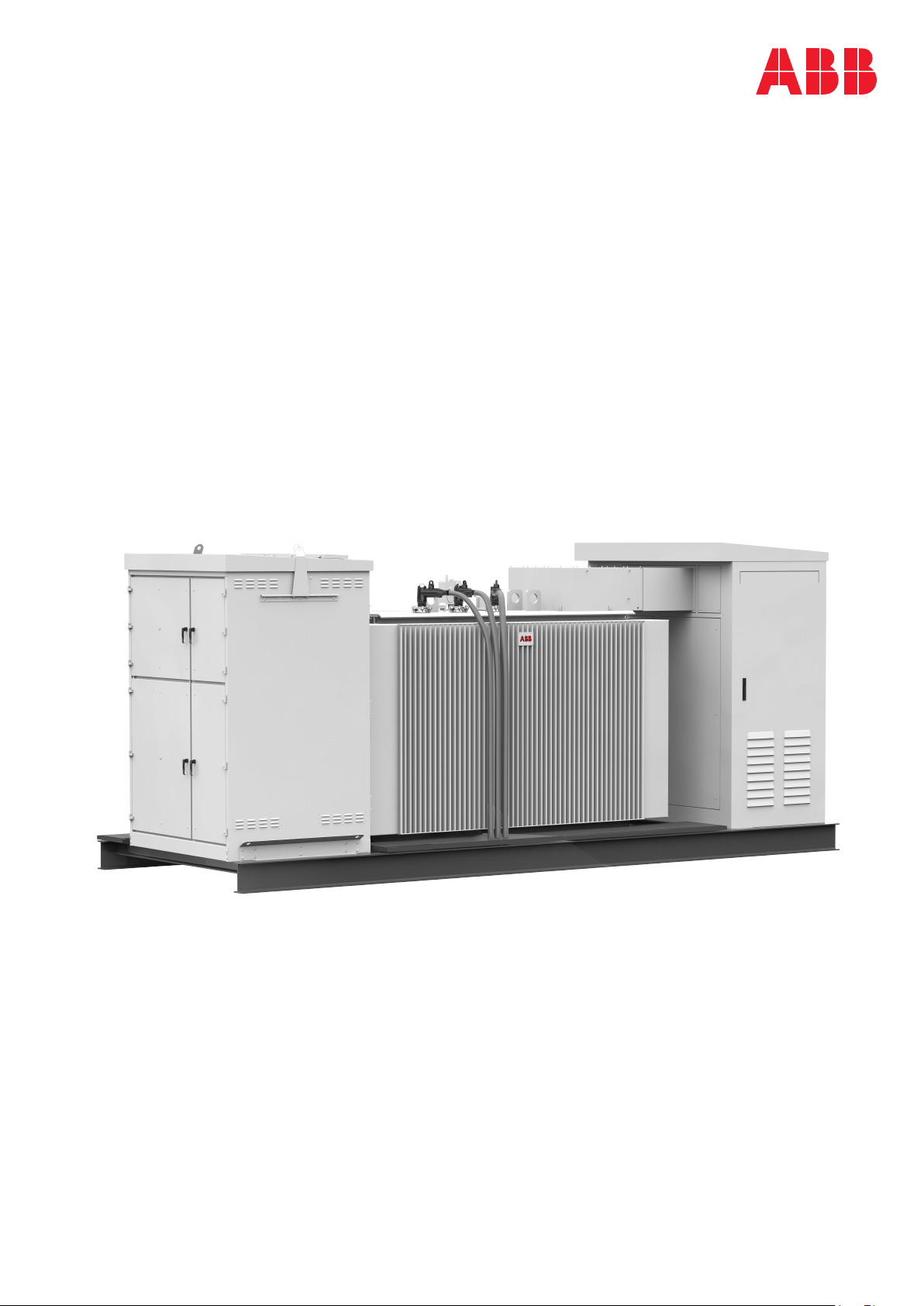
PVS-100/120 medium voltage compact skid
Hardware manual
Page 2

Page 3

PVS-100/120 medium voltage
compact skid
Hardware manual
Table of contents
1. Safety instructions
5. Mechanical installation
6. Electrical installation
8. Start-up and operation
© 2019 ABB Spain. All Rights Reserved. 3AES-PVS-100/120-MVCS-00-MA01-A
Rev A
EN
EFFECTIVE: 2019-05-14
Page 4

Page 5

Table of contents
1 Safety instructions
2 Introduction to this manual
Table of contents 5
9Contents of this chapter . ... ... ... ... ... ... ... ............. . ... . .. . ... . ... ... . ... ... . ... . .. . ... . ..
9Use of warnings .... . ... ... . ... ... . ... . .. . ... . ... ... . ... ... . ... ... . ... . .. . ... . ... ... . ... ... . ... . .. .
10Allowed usage ... ... . ... ... . ... . .. . ... . ... ... . ... ... . ... . .. . ... . .. . ... . ... ... . ... ... . ... . .. . ... . ...
10Safe installation, start-up and maintenance .. . ... . ... ... . ... ... . ... . .. . ... . ... ... . ... ... . ... .
10General safety instructions .... . ... . .. . ... . .. . ... . ... ... . ... ... . ... . .. . ... . ... ... . ... ... . ... . .
11MVCS working area safety . ... . ... . .. . ... . ... ... . ... ... . ... . .. . ... . .. . ... . ... ... . ... ... . ... . .
11Personal protective equipment (PPE) . . ... ... . ... ... . ... ... . ... . .. . ... . ... ... . ... ... . ..
11Safety instructions for MV switchgear and MV transformer area ... . ... . ... ... . ... .
12Safety instructions for the auxiliary services board . ... . ... ... . ... ... . ... ... . ... . .. . ..
13Safe operation ... ... . ... . .. . ... . ... ... . ... ... . ... ... . ... . .. . ... . ... ... . ... ... . ... . .. . ... . ... ... . ...
3 Hardware description
15Contents of this chapter . ... . ... . .. . ... . ... ... . ... ... . ... . .. . ... . ... ... . ... ... . ... ... . ... . .. . ... . .
15Applicability . . ... ... . ... . .. . ... . ... ... . ... ... . ... . .. . ... . ... ... . ... ... . ... ... . ... . .. . ... . ... ... . ... .
15Target audience ... ... . ... ... . ... . .. . ... . ... ... . ... ... . ... ... . ... . .. . ... . ... ... . ... ... . ... . .. . ... . .
15Related documents ... ... . ... ... . ... . .. . ... . ... ... . ... ... . ... . .. . ... . ... ... . ... ... . ... ... . ... . .. . .
16Terms and abbreviations .... . ... ... . ... ... . ... . .. . ... . ... ... . ... ... . ... ... . ... . .. . ... . ... ... . ... .
17Contents of this chapter . ... . ... . .. . ... . ... ... . ... ... . ... . .. . ... . ... ... . ... ... . ... ... . ... . .. . ... . .
17Product overview ... ... . ... ... . ... . .. . ... . ... ... . ... ... . ... . .. . ... . ... ... . ... ... . ... ... . ... . .. . ... .
17External dimensions ... ... . ... ... . ... . .. . ... . ... ... . ... ... . ... . .. . ... . ... ... . ... ... . ... ... . ... . .. .
18Layout drawing ... ... . ... ... . ... . .. . ... . ... ... . ... ... . ... ... . ... . .. . ... . ... ... . ... ... . ... . .. . ... . ..
18Working areas and main components ... . ... ... . ... . .. . ... . ... ... . ... ... . ... . .. . ... . ... ... . ...
19Main components ... ... . ... ... . ... . .. . ... . ... ... . ... ... . ... ... . ... . .. . ... . ... ... . ... ... . ... . ..
20AC cabinet components .... . ... ... . ... . .. . ... . ... ... . ... ... . ... ... . ... . .. . ... . ... ... . ... ... . .
20Inverter inputs ... ... . ... ... . ... . .. . ... . ... ... . ... ... . ... . .. . ... . ... ... . ... ... . ... ... . ... . .. . ... .
20Auxiliary service board .... . ... ... . ... ... . ... . .. . ... . ... ... . ... ... . ... ... . ... . .. . ... . ... ... . ..
22MV switchgear ... ... . ... ... . ... . .. . ... . ... ... . ... ... . ... . .. . ... . .. . ... . ... ... . ... ... . ... . .. . ...
22MV switchgear circuit .... . ... ... . ... . .. . ... . .. . ... . ... ... . ... ... . ... . .. . ... . ... ... . ... ... . .
23MV transformer ... ... . ... ... . ... . .. . ... . ... ... . ... ... . ... . .. . ... . ... ... . ... ... . ... ... . ... . .. . ..
24String inverter ... ... . ... . .. . ... . .. . ... . ... ... . ... ... . ... . .. . ... . ... ... . ... ... . ... ... . ... . .. . ... .
24Main circuit diagram .... . ... ... . ... ... . ... . .. . ... . ... ... . ... ... . ... ... . ... . .. . ... . ... ... . ... ... . ..
25Type designation label .. . ... . ... ... . ... ... . ... . .. . ... . ... ... . ... ... . ... . .. . ... . .. . ... . ... ... . ... .
26Type designation key .. . ... . ... ... . ... ... . ... . .. . ... . ... ... . ... ... . ... ... . ... . .. . ... . ... ... . ... ...
26MVCS optional codes .... . ... ... . ... . .. . ... . ... ... . ... ... . ... ... . ... . .. . ... . ... ... . ... ... . ... .
4 Storing, lifting and transporting
29Contents of this chapter . ... . ... . .. . ... . ... ... . ... ... . ... . .. . ... . ... ... . ... ... . ... ... . ... . .. . ... . .
30Storing . . ... ... . ... . .. . ... . ... ... . ... ... . ... . .. . ... . .. . ... . ... ... . ... ... . ... . .. . ... . ... ... . ... ... . ...
30Conditions for using desiccant bags .. . ... ... . ... . .. . ... . ... ... . ... ... . ... . .. . ... . ... ... . ...
31Lifting . . ... ... . ... . .. . ... . ... ... . ... ... . ... . .. . ... . .. . ... . ... ... . ... ... . ... . .. . ... . ... ... . ... ... . ... .
31Tools used for lifting . ... . ... . .. . ... . .. . ... . ... ... . ... ... . ... . .. . ... . ... ... . ... ... . ... . .. . ... . ..
32Lifting instructions ... ... . ... . .. . ... . ... ... . ... ... . ... . .. . ... . ... ... . ... ... . ... ... . ... . .. . ... . ..
Page 6

6 Table of contents
5 Mechanical installation
6 Electrical installation
33Transporting ... . ... . ... ... . ... ... . ... ... . ... . .. . ... . ... ... . ... ... . ... . .. . ... . .. . ... . ... ... . ... ... . .
33Incoming inspection at arrival . ... . ... . .. . ... . ... ... . ... ... . ... ... . ... . .. . ... . ... ... . ... ... . .
34Unloading . . ... ... . ... . .. . ... . .. . ... . ... ... . ... ... . ... . .. . ... . ... ... . ... ... . ... . .. . ... . .. . ... . ... ...
34Tools used for unloading . ... . ... ... . ... . .. . ... . ... ... . ... ... . ... . .. . ... . .. . ... . ... ... . ... ... .
35Unloading instructions ... ... . ... . .. . ... . ... ... . ... ... . ... ... . ... . .. . ... . ... ... . ... ... . ... . .. . .
37Contents of this chapter . ... . ... . .. . ... . ... ... . ... ... . ... . .. . ... . ... ... . ... ... . ... ... . ... . .. . ... . .
37Safety . . ... ... . ... . .. . ... . ... ... . ... ... . ... . .. . ... . ... ... . ... ... . ... ... . ... . .. . ... . ... ... . ... ... . ... .
37Tools . . ... ... . ... ... . ... . .. . ... . ... ... . ... ... . ... . .. . ... . .. . ... . ... ... . ... ... . ... . .. . ... . ... ... . ... ..
37Foundation guidelines ... ... . ... . .. . ... . ... ... . ... ... . ... ... . ... . .. . ... . ... ... . ... ... . ... . .. . ... . .
38Placing the MVCS on the foundation .... . .. . ... . ... ... . ... ... . ... ... . ... . .. . ... . ... ... . ... ... .
39Fastening the MVCS .... . ... ... . ... . .. . ... . ... ... . ... ... . ... . .. . ... . ... ... . ... ... . ... ... . ... . .. . .
39Constructing earthing electrode and earthing .. . ... . .. . ... . ... ... . ... ... . ... . .. . ... . ... ... . ..
40Filling the pit and finalizing the surroundings . ... . .. . ... . ... ... . ... ... . ... . .. . ... . ... ... . ... ..
41Contents of this chapter . ... . ... . .. . ... . ... ... . ... ... . ... . .. . ... . ... ... . ... ... . ... ... . ... . .. . ... . .
42Routing the cables .... . ... ... . ... ... . ... . .. . ... . ... ... . ... ... . ... . .. . ... . ... ... . ... ... . ... ... . ... .
42Earthing . . ... ... . ... . .. . ... . ... ... . ... ... . ... . .. . ... . ... ... . ... ... . ... ... . ... . .. . ... . ... ... . ... ... . .
42Protective earthing (grounding) inside the MVCS .... . .. . ... . ... ... . ... ... . ... . .. . ... . ... ... .
42Measuring the insulation resistance of the cabling . ... . .. . ... . ... ... . ... ... . ... . .. . ... . ... ..
43Connecting the inverter inputs . . .. . ... . .. . ... . ... ... . ... ... . ... . .. . ... . ... ... . ... ... . ... ... . ... .
45Connecting the communication and auxiliary cabling (Optional) . ... . ... ... . ... ... . ... . .. .
45Connecting the power grid cabling to the MV switchgear ... . ... . .. . ... . ... ... . ... ... . ... ...
7 Finalizing the installation
8 Start-up and operation
9 Maintenance
47Contents of this chapter . ... . ... . .. . ... . ... ... . ... ... . ... . .. . ... . ... ... . ... ... . ... ... . ... . .. . ... . .
47Finalizing the installation .... . ... . .. . ... . ... ... . ... ... . ... ... . ... . .. . ... . ... ... . ... ... . ... . .. . ... .
48Landscaping the station .... . ... ... . ... . .. . ... . ... ... . ... ... . ... ... . ... . .. . ... . ... ... . ... ... . ... . .
48Checking the installation of MVCS .. . ... . .. . ... . ... ... . ... ... . ... . .. . ... . ... ... . ... ... . ... ... . .
49Contents of this chapter . ... . ... . .. . ... . ... ... . ... ... . ... . .. . ... . ... ... . ... ... . ... ... . ... . .. . ... . .
49Tools needed ... ... . ... ... . ... ... . ... . .. . ... . ... ... . ... ... . ... . .. . ... . ... ... . ... ... . ... ... . ... . .. . .
49Prerequisite . . ... ... . ... . .. . ... . ... ... . ... ... . ... . .. . ... . ... ... . ... ... . ... ... . ... . .. . ... . ... ... . ... .
50Start-up procedure ... ... . ... . .. . ... . ... ... . ... ... . ... ... . ... . .. . ... . ... ... . ... ... . ... . .. . ... . ... ..
53Contents of this chapter . ... . ... . .. . ... . ... ... . ... ... . ... . .. . ... . ... ... . ... ... . ... ... . ... . .. . ... . .
53Tools list ... ... . ... ... . ... . .. . ... . .. . ... . ... ... . ... ... . ... . .. . ... . ... ... . ... ... . ... ... . ... . .. . ... . ...
54Tightening torque . ... ... . ... ... . ... . .. . ... . ... ... . ... ... . ... ... . ... . .. . ... . ... ... . ... ... . ... . .. . ..
55Maintenance intervals ... ... . ... . .. . ... . .. . ... . ... ... . ... ... . ... . .. . ... . ... ... . ... ... . ... . .. . ... . .
55Maintenance activities ... ... . ... . .. . ... . ... ... . ... ... . ... ... . ... . .. . ... . ... ... . ... ... . ... . .. . .
56Maintenance intervals ... ... . ... ... . ... . .. . ... . ... ... . ... ... . ... . .. . ... . ... ... . ... ... . ... ... . .
56Cleaning procedure ... ... . ... ... . ... . .. . ... . ... ... . ... ... . ... ... . ... . .. . ... . ... ... . ... ... . ... . .. . .
57Maintenance of painted surfaces . . .. . ... . .. . ... . ... ... . ... ... . ... . .. . ... . ... ... . ... ... . ... ... . .
57Repainting the scratched areas . ... . ... . .. . ... . ... ... . ... ... . ... . .. . ... . .. . ... . ... ... . ... ...
57Tools and materials .... . ... ... . ... ... . ... . .. . ... . ... ... . ... ... . ... ... . ... . .. . ... . ... ... . ...
58Painting the damaged surface (no visible rust) .. ... . ... ... . ... ... . ... . .. . ... . ... ... . .
Page 7

10 Technical data
11 Drawings
Further information
Table of contents 7
58Painting the damaged surface (visible rust) .... . ... ... . ... ... . ... . .. . ... . ... ... . ... ...
58Maintenance of Zinc coated surfaces .. . ... . .. . ... . ... ... . ... ... . ... ... . ... . .. . ... . ... ... . .
58Maintenance of grounding bars and points .... ... . ... ... . ... . .. . ... . ... ... . ... ... . ... . .. . ... .
58Tools . . ... ... . ... ... . ... . .. . ... . ... ... . ... ... . ... ... . ... . .. . ... . ... ... . ... ... . ... . .. . ... . ... ... . ..
59Procedure . . ... ... . ... . .. . ... . ... ... . ... ... . ... ... . ... . .. . ... . ... ... . ... ... . ... . .. . ... . ... ... . ..
61Contents of this chapter . ... . ... . .. . ... . ... ... . ... ... . ... . .. . ... . ... ... . ... ... . ... ... . ... . .. . ... . .
62Technical data and types: PVS-100 MVCS .... . ... ... . ... . .. . ... . ... ... . ... ... . ... . .. . ... . ..
64Technical data and types: PVS-120 MVCS .... . .. . ... . ... ... . ... ... . ... . .. . ... . ... ... . ... ... .
67Contents of this chapter . ... . ... . .. . ... . ... ... . ... ... . ... . .. . ... . ... ... . ... ... . ... ... . ... . .. . ... . .
67List of technical drawings . ... . ... . .. . ... . ... ... . ... ... . ... ... . ... . .. . ... . ... ... . ... ... . ... . .. . ...
Page 8

8
Page 9
Safety instructions
Safety instructions 9
1
Contents of this chapter
This chapter presents the use of warnings in the manual and gives instructions for safe
installation, start-up, use and maintenance of the PVS-100/120 medium voltage compact
skid (MVCS).
Use of warnings
Warnings caution you about conditions which can result in serious injury or death and/or
damage to the equipment, and advise on how to avoid the danger. The following warning
symbols are used in this manual:
WARNING!
Electricity warning warns of hazards from electricity which can cause physical
injury and/or damage to the equipment.
WARNING!
General warning warns about conditions, other than those caused by electricity
which can result in physical injury and/or damage to the equipment.
WARNING!
General warning warns about weather conditions, prohibited maintenance
operations during a typhoon, thunderstorm, snow, rain and electrical storm.
Maintenance in such conditions can result in physical injury and/or damage to the
equipment.
Page 10

10 Safety instructions
WARNING!
General warning warns about maintenance work on the roof which should always
be done from the outer perimeter, considering the local safety regulations.
Allowed usage
• The PVS-100/120 medium voltage compact skid (MVCS) is designed to transform AC
current from a group of inverters and finally feed to a medium voltage grid. Use the
MVCS only at its permissible input/output ratings and ambient conditions. Make sure
this compliance is satisfied before commissioning.
• The operation and maintenance of the MVCS must be carried out by certified technicians
that fulfill all local skill set and safety requirements. Any unqualified personnel must
maintain a safe distance from the MVCS. All activities must be in accordance with the
criteria described in the ABB technical documents and local regulations.
• Make changes to the MVCS only with the direct authorization of ABB. Any alterations
done outside ABB approval will invalid the warranty for the product. ABB is not liable
for any damages caused by these changes.
• The MVCS is a non-walk-in type station, designed to be operated from the outside.
Make sure the side doors are closed at all times during operation and that no personnel
is inside or in the near vicinity of the MVCS.
Safe installation, start-up and maintenance
This section contains the safety instructions which you must follow when installing,
commissioning and maintaining the MVCS. If ignored, physical injury or death may follow,
or damage may occur to the equipment.
• Only authorized electricians are allowed to install, start-up and maintain the MVCS.
Working methods, tools, components etc. must follow the IEC regulations.
• Obey all local safety regulations concerning electrical stations.
• The MVCS should be energized and de-energized only by an authorized person who
has the task-specific instructions for the operation of an MV substation and permission
from the on-site foreperson in charge of electrical work.
• If other people must be in the vicinity while the door is open, warn them, and if required,
provide supervision and guidance.
■ General safety instructions
WARNING!
Before you perform any work in the MVCS, obey the following safety precautions.
1. Clearly identify the work location.
2. Read the safety instructions of the work area and the component you are working on.
See the subsections below and the component-specific manuals.
3. Disconnect and secure against reconnection.
4. Disconnect all possible power supplies (external, auxiliary and inverters) and open all
base fuse switches. Lock the disconnectors in the open position and attach a warning
notice to them. After disconnecting power to the inverters, always wait until the stored
energy of the inverters is discharged. See also, inverters manual.
5. Use protection against any live parts.
Page 11
Safety instructions 11
6. Take special precautions when you work close to exposed conductors.
7. Measure to ensure that there is no voltage connected.
8. Carry out earthing (grounding) and short circuiting.
9. Issue a permit to work.
■ MVCS working area safety
The MVCS has three working areas:
• AC Cabinet Area
• MV Transformer Area
• MV Switchgear Area
Each work area has separate safety instructions.
Personal protective equipment (PPE)
• Perform any operation on the equipment with suitable work clothes and instruments.
• When choosing a personnel protective equipment, consider environmental conditions
such as humidity, noise, etc. and local regulations.
• Make sure the work clothes and accessories are not prone to generate electrostatic
charges, fires or any other condition that compromises personnel safety.
• The minimum required safety equipment is as follows:
• Safety shoes
• Safety gloves
• Safety glasses
• Head protection
• Hearing protection
• Work clothes
Safety instructions for MV switchgear and MV transformer area
WARNING!
Perform the below instructions before you start working inside the MV switchgear
and/or MV transformer area. Ignoring the instructions can cause physical injury or
death, or damage to the equipment.
1. Identify the MV switchgear and read its safety instructions.
2. Check the operation of the capacitive voltage indicators in all MV switchgear bays (all
phase LEDs are switched on when a voltage is connected).
3. Disconnect the MV switchgear from all possible power supplies (external, auxiliary, and
inverters as well as any parallel connection stations), and secure by locking and tagging.
a. Stop the string inverters outside the MVCS. Open the DC disconnecting switches
in each inverter unit and add warning notices. If applicable, open the AC
disconnecting switches in each inverter unit, lock and add warning notices.
b. Open all fuse base switches of the inverter inputs, lock and add warning notices.
c. Open all auxiliary breakers, switches and fuses in the auxiliary service board, lock
and add warning notices.
d. Turn the vacuum circuit breaker of the MV switchgear to open position. Lock and
add warning notice.
Page 12

12 Safety instructions
e. Turn the disconnecting switch of the MV transformer side of the MV switchgear to
open position. Lock and add a warning notice.
f. Disconnect the MV switchgear from the MV network (all possible external power
supplies, grid and parallel stations). See the User's manual of the MV switchgear.
Lock and add warning notices.
4. Check that all shrouds/screens are in place.
5. Check that you are not near to any live parts while working. All live circuits must be
protected with shrouds/screens.
6. Make sure that the MV switchgear is dead.
• Check the status of voltage indicators in all MV switchgear bays. Note that all phase
LEDs which were switched on AC cabinet at step 3 are now switched off).
7. Earth the MV switchgear and AC cabinet.
• Turn the earthing switches of the MV switchgear to “earthed” position, lock (remove
the MV switchgear Ronnis key of the V module) and add warning notices. If the
station is connected to parallel stations, make sure that you also turn the appropriate
earthing switches of the parallel stations to “earthed” position.
• Temporarily, ground the MV switchgear terminals at all possible external power
supplies (grid and parallel stations). See the User's manual of the MV switchgear.
Lock and add warning notices.
• Ground the inverter AC sides with appropriate temporary grounding set.
8. Check that the MV transformer is dead (high voltage terminals, low voltage terminals,
any auxiliary power, and instrumentation). Use an appropriate high voltage tester only
for the high voltage side, and a voltage detector with suitable testing heads for the low
voltage side.
9. Issue a work permit.
Safety instructions for the auxiliary services board
1. Open the main circuit breaker or main switch of the auxiliary service transformer, and
secure by locking and tagging.
2. Open the secondary circuit breaker of the auxiliary service transformer, and secure by
locking and tagging.
3. Open all switches, breakers and connectors of the auxiliary service board, and secure
by locking and tagging.
4. Make sure you are not near to any live parts while working. Disconnect the live circuits
or protect them with shrouds/screens.
5. Check the status of the voltage indicators in the auxiliary service board.
6. Check that the auxiliary service board is dead.
7. Issue a work permit.
Page 13
Safety instructions 13
Safe operation
This section contains the safety instructions which you must follow when operating the
MVCS. If ignored, physical injury or death, or damage may occur.
WARNING!
Obey these instructions to prevent injury, death, or damage to the equipment
WARNING!
Keep all doors locked while the MVCS is operating. Allow access to only authorized
personnel.
1. Keep all doors of the MVCS closed during operation. Give the keys only to authorized
personnel.
2. Before you start a group of inverters, check the connections of each inverter input, and
the recommendations in the specific inverter manual.
3. Do not open the AC base fuse switches when the MVCS is operating.
4. Before you adjust the group of inverters and set them into service, make sure that all
of them are suitable for operation.
5. Do not use the inverters in a manner not specified in the manual.
Note:
• Spend as little time as possible near the inverters or the MVCS.
• Use a personal computer with a communication cable of sufficient length when you
monitor or adjust inverter parameters during operation.
Page 14

14
Page 15

Introduction to this manual
Introduction to this manual 15
2
Contents of this chapter
This chapter provides information about the manual such as applicability, target audience
and contents. It also lists the related documents.
Applicability
This manual is applicable to PVS-100/120 medium voltage compact skid (MVCS).
Target audience
This manual is intended for persons who transport, store, plan the installation, install,
commission and maintain the MVCS.
Read this manual before working on the MVCS. You are expected to know the fundamentals
of electricity, wiring, electrical components and electrical schematic symbols.
Related documents
Code (English)Document
Inverter manuals and guides
9AKK107045A7607PVS-100/120-TL Product Manual
9AKK107492A2231PVS-100/120-TL Quick Installation Guide
Option manuals and guides
9AKK107046A0405DRMO-INTERFACE- Quick Installation Guide
9AKK10103A3456String inverter- Product Manual Appendix
Other manuals and guides
1YVA000024SafeRing/SafePlus 24 kV SF6 insulated Ring Main Unit and Compact
Switchgear
Page 16
16 Introduction to this manual
Switchgear
List of drawings
See list in chapter Drawings (page 67).
Note: The drawings are delivered with the unit only on request.
Terms and abbreviations
DescriptionTerm/
Abbreviation
Alternating currentAC
Construction of MV switchgearCV/CCV
Direct currentDC
High cube containerHC
Low voltage (50...1000 V AC)LV
Medium voltageMV
Medium voltage compact skidMVCS
Personal protective equipmentPPE
Sulfur hexafluoride (this gas type is used in MV switchgear).SF6
SwitchgearSWG
Total harmonic distortionTHD
Code (English)Document
1YVA000026SafeRing/SafePlus 36 kV SF6 insulated Ring Main Unit and Compact
-
Page 17

Hardware description
Hardware description 17
3
Contents of this chapter
This chapter provides an overview of the PVS-100/120 medium voltage compact skid
(MVCS). It also includes layout, type designation label and type designation information.
Product overview
The PVS-100/120 medium voltage compact skid connects a group of inverters to a medium
voltage power grid. This solution is constructed around a skid house that contains:
• MV transformer—transforms low voltage from inverters to medium voltage for the
power grid.
• Auxiliary service transformer—supplies power to the AC cabinet and auxiliary
components of the MVCS.
• MV switchgear—connects to the power grid. It is also the main protecting, switching,
breaking and disconnecting equipment of the medium-voltage side of the solar power
plant.
• AC cabinet—contains all parallel connections to the inverter inputs and the auxiliary
service boards (required for the autonomous function of the MVCS). Note that the AC
cabinet also includes an additional space for customer use (e.g. communication board,
etc.).
External dimensions
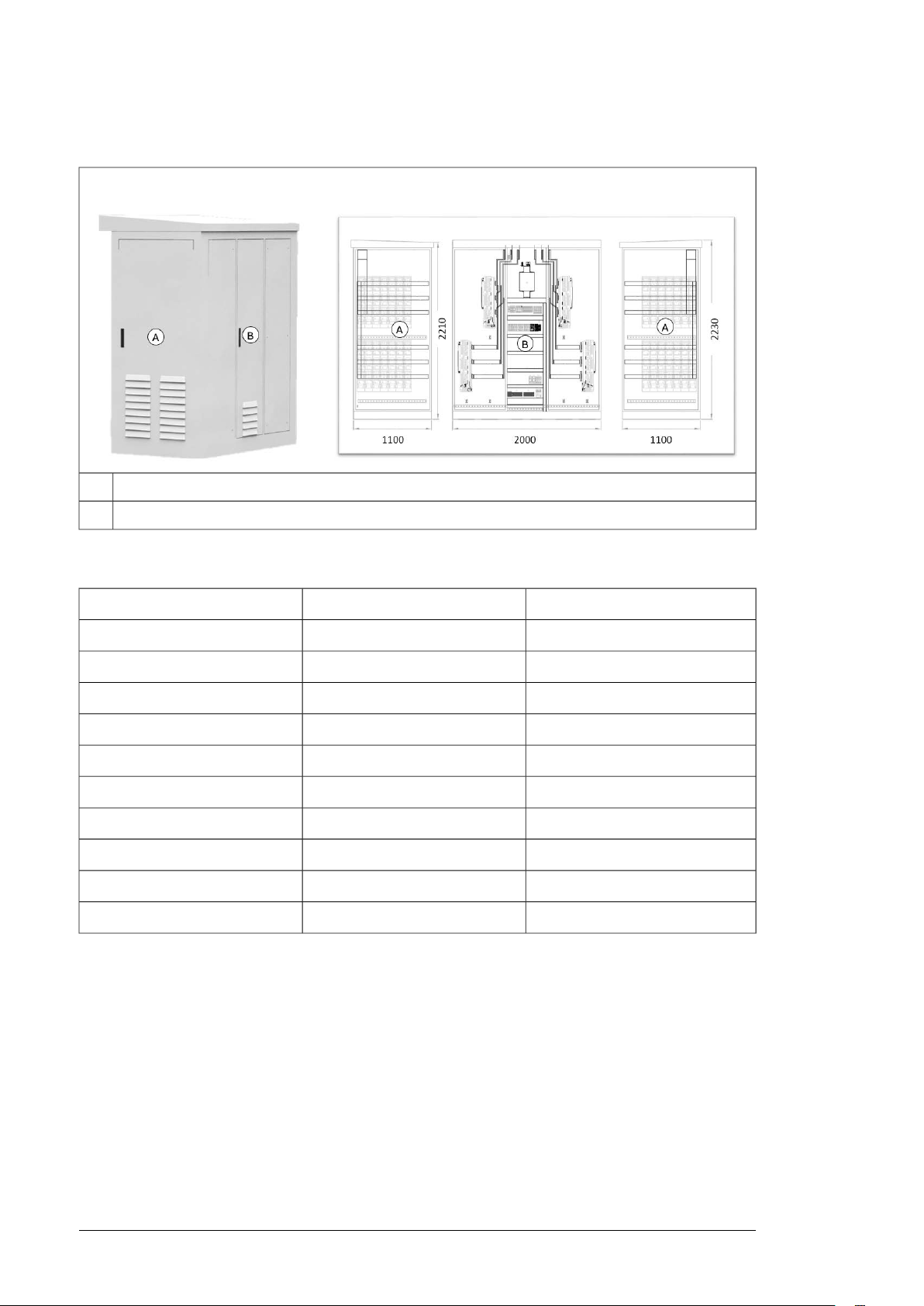
The MVCS is constructed over a skid suitable for transportation inside a 20 HC container
with,
• External dimension (length, width, height) = 5700 x 2150 x 2500 mm
• Total weight = 11 ton.
Page 18

:
A
B
C
18 Hardware description
Layout drawing
This section describes the working areas and main components of the MVCS. For more
information, see drawing, 3AES-PVS-100_120_MVCS-30-DW01.
Working areas and main components
A
MV switchgear area. For more information, see section MV switchgear (page 22).
B
MV transformer area. For more information, see section MV transformer (page 23).
C
AC cabinet area. For more information, see section AC cabinet components (page 20).
Page 19

■ Main components
39
4
Aux. Breakers and others
1U
Ø200
152
5700
2500
2150
7
8
5
6
6
4
3
2
1
4
3
3
4
9
9
10
12
11
Hardware description 19
A
B
C
MV switchgear1
Lead-through holes for power grid cabling and terminal for external earthing electrode2
SWG cooling air inlet3
SWG cooling air outlet4
AC cabinet cooling air inlet5
AC cabinet cooling air outlet6
Busbar LV connections7
LV bushing / LV box8
HV bushing connections9
Lead-through holes for cabling from MV transformer to MV switchgear10
MV cables access11D
String inverter cables access12E
Page 20
20 Hardware description
■ AC cabinet components
A
Inverter inputs. For more information, see section Inverter inputs (page 20).
B
Auxiliary service board. For more information, see section Auxiliary service board (page 20).
■ Inverter inputs
PVS-120-MVCS-...PVS-100-MVCS-...Inverter inputs
9608008
1200100010
1440120012
1680140014
1920160016
2160180018
2400200020
2640220022
2880240024
3120260026
■ Auxiliary service board
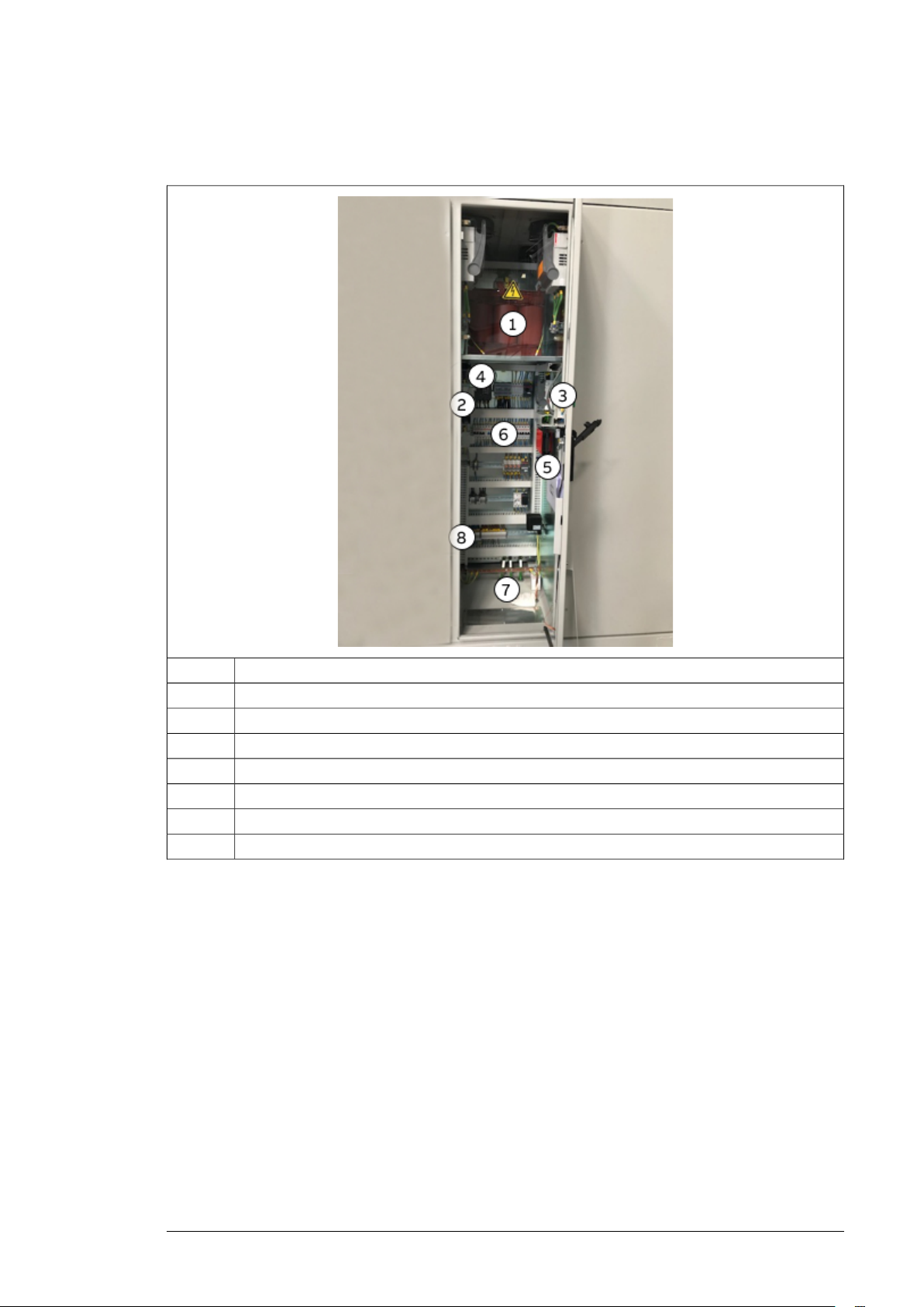
The figure below describes the components of a standard auxiliary service board. Additional
components and customization is included in the project specific documentation.
See also, UPS connection drawing 3AES-PVS-100/120_MVCS-14-SP01.
Page 21
Hardware description 21
Note: Technical drawings are delivered with the unit, only if you requested.
Auxiliary service transformer1
Surge arrester protection for the auxiliary service board2
Upstream on-load fuse switch for auxiliary service transformer protection3
Downstream circuit breaker for auxiliary service transformer protection4
Torch light and charger5
Auxiliary service board circuit breakers and differential protections6
Grounding busbar7
Terminals block8
Page 22
22 Hardware description
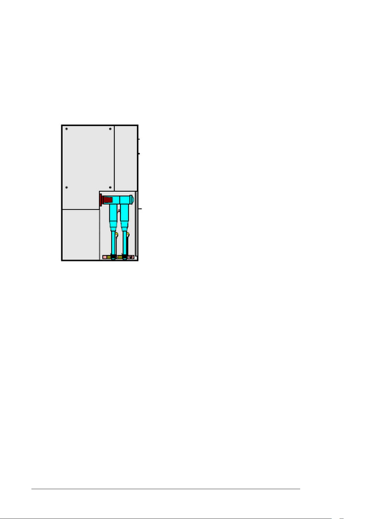
■ MV switchgear
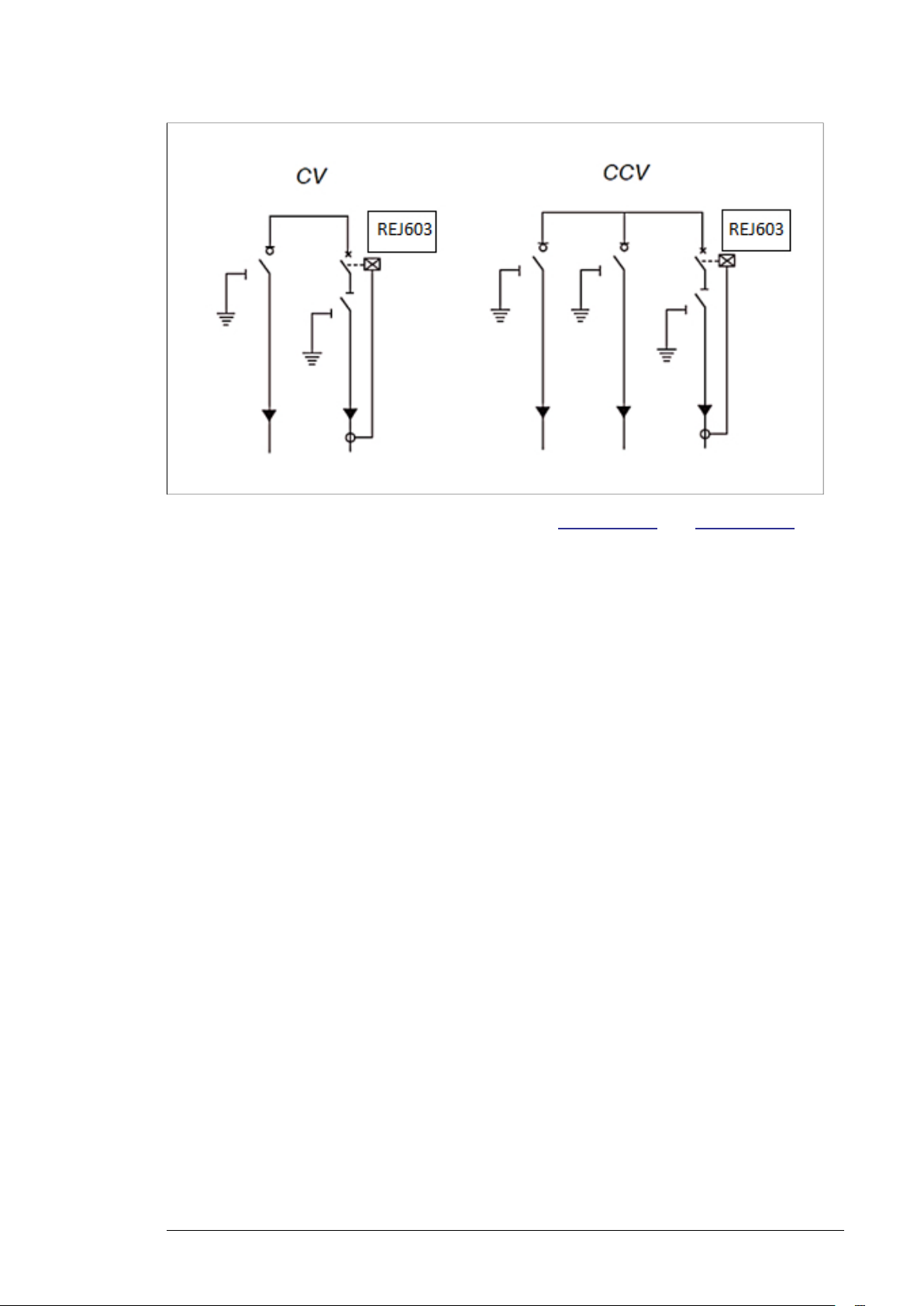
The MVCS is always equipped with outdoor MV switchgear. Type CV is used as the standard
and consists of two modules:
• C uses a double cable bushing configuration to connect to:
1. The grid-side module with grid cable terminals and a disconnecting and earthing
switch. See figure below.
2. The connection of other parallel-connected substations.
• V is the Vacuum circuit breaker module equipped with the Self power relay (REJ 603)
as a standard.
MV switchgear circuit
The diagrams below show the standard CV MV switchgear and optional CCV MV switchgear.
Both the switchgears can be upgraded to V-module motorized and REF615 protection relay
by adding combisensors for metering purpose.
Page 23
Hardware description 23
For more information, see MV switchgear manuals (1YVA000024 and 1YVA000026)
■ MV transformer
See MV transformer manual (1LTR954400-1).
Page 24
-Q0
I>
1
2
3
5
6
7
8 9
10 11 12
4
24 Hardware description
■ String inverter
For information on the inverters, see:
• PVS-100/120-TL Product Manual (9AKK107045A7607)
• String inverter- Product Manual Appendix (9AKK10103A3456)
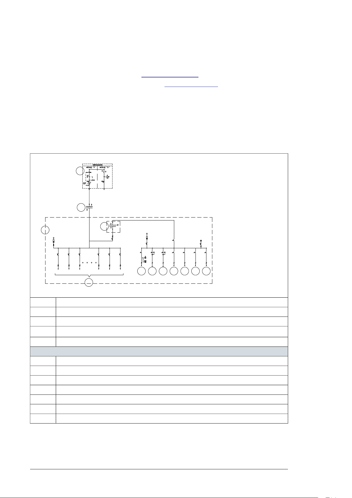
Main circuit diagram
The general single-line diagram depends on the configuration and options of the unit as
well as the configuration of the inverter group. The table below describes the baseline
configuration.
See also, single line diagram 3AES-PVS-100/120_MVCS-01-DW01.
CV MV switchgear (possible to upgrade to CCV)1
MV transformer2
AC cabinet3
4
Inverter inputs. See also, section Inverter inputs (page 20).
Auxiliary service transformer5
Auxiliary service board
AC cabinet heating and fan6
External power socket7
Lighting8
Optional communication cabinet power supply9
MVCS control equipment10
AC cabinet power supply11
Spare12
Page 25
S/N:
NNNNNNNNNNNN
Description:
Medium Voltage Compact Skid
Type Designation:
PVS-100/120 - MVCS - XXXX- Y +options
MADE IN SPAIN
MANUFACTURED IN 20XX
A
B
C
D
E F G
H
I
J
Hardware description 25
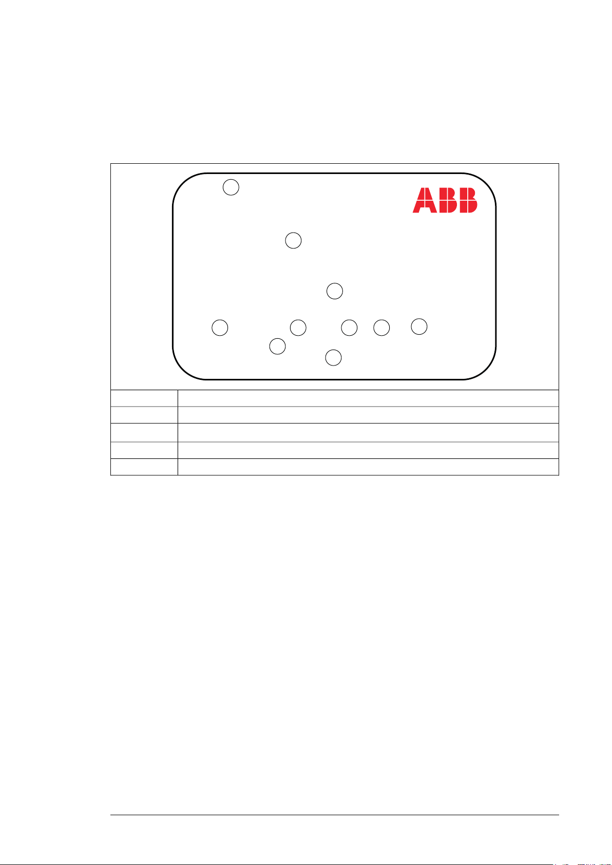
Type designation label
The figure below shows an example of the type designation label. The label contains the
basic data of the unit. It is located inside the AC cabinet in the door to access the Auxiliary
service board.
C
Serial number. Each unit has a unique serial number.A
Description of the unit: Medium Voltage Compact SkidB
Type designation key. For more information, see Type designation key (page 26).
Manufacturing country nameI
Manufacturing yearJ
Page 26
26 Hardware description
Type designation key
The type designation describes the composition of the unit. The type designation is visible
on the type designation label which is attached to the unit. The complete type designation
is divided into sub codes:
• The first 1…18 digits form the basic code which describes the basic construction of the
unit. The fields in the basic code are separated by hyphens.
• The option codes follow the basic code. Each option code starts with an identifying letter
(common for the whole Product Series), followed by descriptive digits. The option codes
are separated by plus signs.
The following table describes the fields of the basic code and the option code. Refer to the
items of figure in Type designation label.
Example: PVS-100/120 - MVCS - XXXX - Y + Options
DescriptionItem
PVS-100/120 = Inverter modelD
MVCS = Station typeE
Power rating
F
G -Y = 480 V
XXXXkVA
See chapter Technical data (page 61).
LV voltage
-Y = 400 V
Option (plus) codes for additional upgradesH
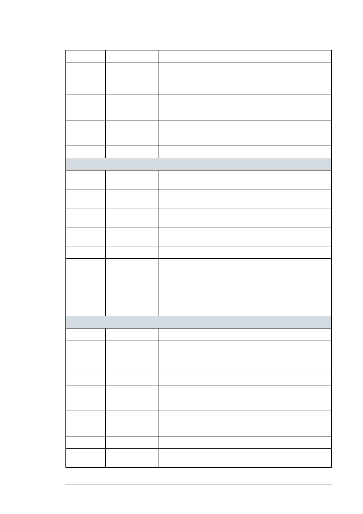
■ MVCS optional codes
+TRECO
+TRC5
+ATR20
+ATR30
Oil transformer ECO
losses
C5 corrosion
protection
degree for
transformer
Auxiliary transformer
power rating
Auxiliary transformer
power rating
DescriptionNameCode
MV oil transformer
Standard losses oil transformer is replaced with eco losses oil transformer
Oil transformer 22kV is replaced with Oil transformer 36kVOil transformer 36kV+TR36kV
Oil transformer 60 Hz is replaced with oil transformer 50 HzOil transformer 50Hz+TR50Hz
Oil transformer corrosion protection degree C4 is replaced with
C5 corrosion protection degree
Oil transformer inrush current is replaced with a lower oneInrush current+TRIn
Auxiliary services
Standard 10 KVA auxiliary service transformer is upgraded to a 20 KVA
400/230 V auxiliary service transformer
Standard 10 KVA auxiliary service transformer is upgraded to a 30 KVA
400/230 V auxiliary service transformer
Page 27
Hardware description 27
DescriptionNameCode
+ATR3
+SPD412
+SPD812
+M24CCV
+M36CCV
Additional monophase auxiliary
transformer power
rating
AC standard surge
protection device
Type I + II 400V
AC standard surge
protection device
type I + II 800V
SafeRing CCV module
SafeRing CCV module
SafeRing module+M2420
SafeRing module+M3625
An additional auxiliary monophase service transformer of 3kVA is installed to provide customer with specified voltage level and frequency
Standard surge protection device type II is replaced with standard surge
protection device type I + II. Only applicable for PVS-100/120 solutions
Standard surge protection device type II is replaced with standard surge
protection device type I + II. Only applicable for PVS-175 solutions
Addition of a main circuit breakerMain circuit breaker+MCB
MV switchgear
Standard 24kV CV SafeRing switchgear is replaced with SafeRing CCV
switchgear only for RMU 24kV RMU
Standard 36kV CV SafeRing switchgear is replaced with SafeRing CCV
switchgear only for RMU 36kV RMU
SafeRing switchgear 24kV 16kA is replaced with SafeRing switchgear
24kV 20 kA only for RMU 24kV RMU
SafeRing switchgear 36kV 20kA is replaced with SafeRing switchgear
36kV 25 Ka only for RMU 36kV RMU and 50 Hz
+MREF6
+MREFS
+C5M
+COM2
+COM1
Feeder protection
and control relay
REF615
Feeder protection
and control relay
REF615 and AC MV
metering
C5-M corrosion protection
degree
for enclosure
communication
board 1
Basic
communication
board 2
Manual V module is replaced with motorized V moduleMotorized V module+MMOTO
Standard self-powered protection relay REJ603 is replaced with extensive protection relay REF615. Including current transducers (voltage
protection not included in this option)
Standard self-powered protection relay REJ603 is replaced with extensive protection relay REF615 and combisensors for
measuring and voltage protections
Station (skid)
Supply of a transformer fence around the transformer perimeterTransformer fence+TRFENCE
Enclosure and MV transformer standard C4 corrosion degree is upgraded to C5M corrosion degree Also select the upgrade of C5 protection for the oil transformer (+ TRC5). This option is
recommended for sites near sea (>10 km).
Concentration of all the signals of the station in one pointSignal concentration+SIGC
Communication board for projects of 1 stationBasic
Communication board for projects of >1 station, for communication
between stations
+HVBOX
MV bushing
protection box
Metallic cable glands an MV bushing interlocking systemFrench add-ons+FRADD
Installation of a HV box to protect the HV bushings of the
transformer
Page 28

28 Hardware description
DescriptionNameCode
+UPS3
+UPS6
+UPS10
+JP HR test
+JP SC calc
+EW-60/64
UPS power value
3kVA
UPS power value
6kVA
10kVA
Non IEC cable colors+COLOR
former heat run test
former short circuit
calculation
Extended warranty
60/64 months
UPS with capacity of 3kVA (6min) / 2kVA (8min) /1kVA (20min) /0,5kVA
(48min) /0,3kVA (95min) Installation included
UPS with capacity of 6kVA (10min) / 4kVA (17min) /3kVA (23min) /2kVA
(42min) /1kVA (84min). Installation included
UPS with capacity of 10kVA (6min) / 8kVA (8min). Installation includedUPS power value
IEC standard cable colors are replaced with cables with
customized colors
Tests
JP transformer heat run test (one per transformer)Japan MV trans-
JP Transformer short circuit calculation (one per transformer)Japan MV trans-
Warranty
The warranty is extended to 60 months from commissioning or 64
months from delivery (whichever happens first).
Page 29
Storing, lifting and transporting 29
4
Storing, lifting and transporting
Contents of this chapter
This chapter provides instructions for storing, lifting and transporting the PVS-100/120
medium voltage compact skid (MVCS).
WARNING!
Inspect carefully the container before performing any activity. Verify that the MVCS
has no protuberance, lack of rings, or any general poor condition.
WARNING!
Ignoring the following instructions can cause physical injury or death, or damage
to the equipment:
• Use only authorized lifting equipment and personnel.
• Prevent anybody getting under the load.
• Do not stand on the roof while fastening the lifting slings or while lifting.
• Do not throw slings or hooks onto the roof.
WARNING!
Use original silica gel bags only during transport. Install new silica gel bags for
storage.
Page 30

30 Storing, lifting and transporting
Storing
WARNING!
To prevent damage to the MVCS, keep the delivery packaging and protection
canvas on until you install it.
• Always store the MVCS in upright position.
• Protect the MVCS from rainwater and dust. Use covers for air outlets. Avoid opening
the doors unnecessarily and remove the transportation plates during storage and at the
time of installation.
• If removing the MVCS from protective packaging and if condensation is possible in the
storage area, follow the below conditions:
• Supply power to the internal heaters to maintain the inside temperature of the unit
more than the outside temperature.
• If power supply is not available, add humidity desiccant bags inside the station.
• If the MVCS is stored for more than two weeks without using electric heaters, use
desiccant bags. See also, Conditions for using desiccant bags (page 30).
• Make sure the ground underneath the MVCS is solid, flat, dry and vegetation-free. The
ground must support the station evenly from below and there should not be any twisting
or stress. Do not place the MVCS directly onto the bare ground because this could
damage the paint and cause corrosion.
• Place the MVCS on wooden support beams. Locate the beams under the four corners
and the middle points.
■ Conditions for using desiccant bags
• Hang the desiccant bags approximately 1 m from the floor.
• Use 500 grams of desiccant per week. For example, for four weeks of storage, use 2
kg of desiccant bags.
• Replace the bags with fresh bags every four weeks.
• Do not open the doors unnecessarily during the storage period.
• Examples of suitable container desiccants: Xdry desiccants “H model” or Clariant
“Container Dri®II- Pole”.
Note: The MVCS is delivered with desiccant bags from factory as standard.
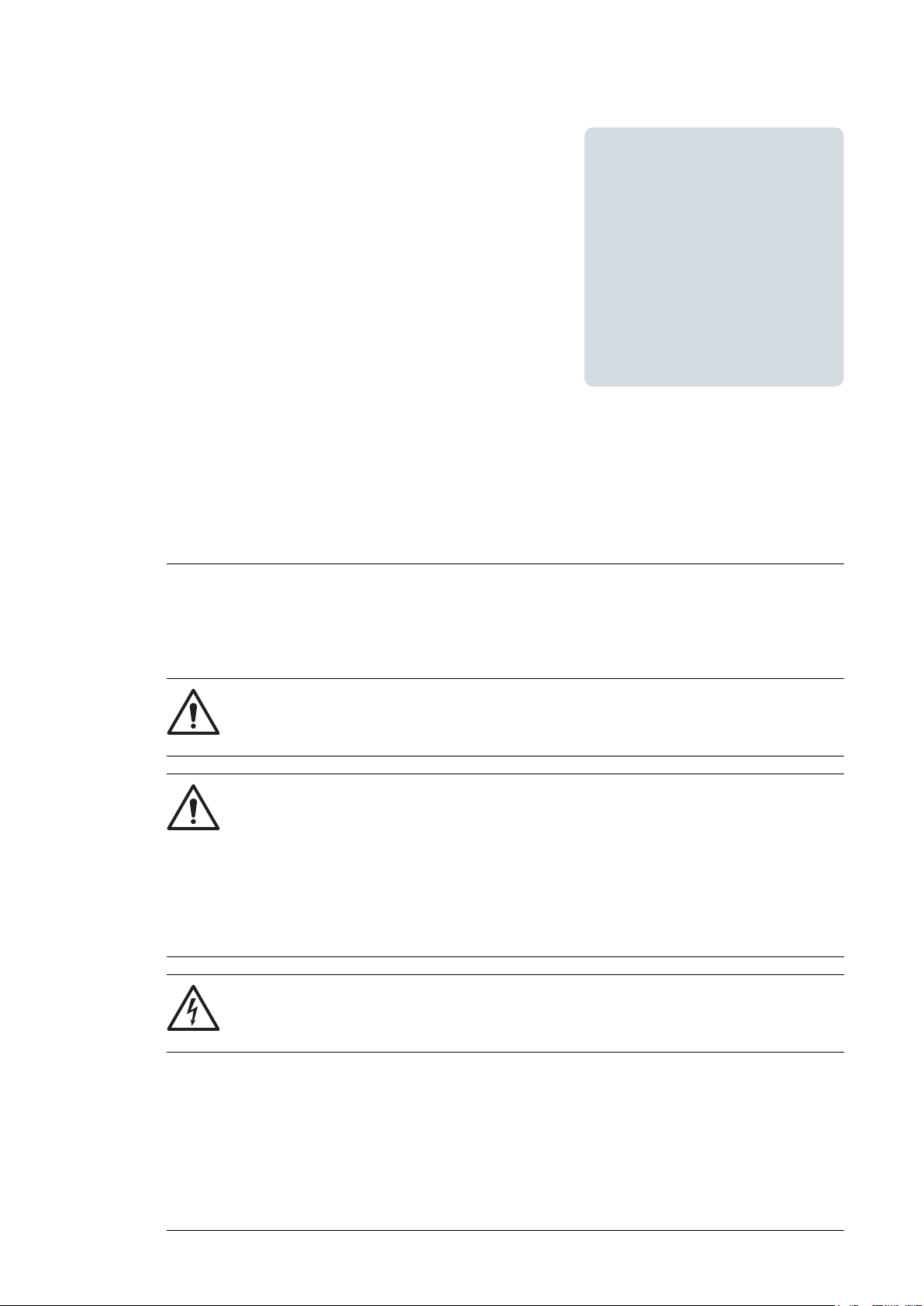
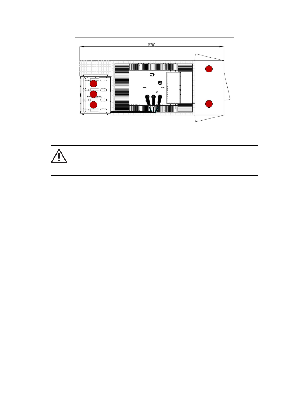
The below figure shows the locations of desiccant bags, marked in red.
Page 31
Lifting
Storing, lifting and transporting 31
WARNING!
Inspect the container before any activity. Make sure that the container has no
protuberance, enough rings and is in good condition. Ignorance of this message
can cause physical injury, death or damage to the equipment.
Before lifting the MVCS, follow these instructions.
• Protect the corners of the MVCS against shock.
• The minimum rated loading capacity of each sling is eight tons.
• The minimum length of each sling is five meters.
• Adjust the length of lifting slings so that the MVCS does not tilt during lifting.
• Do not allow the lifting slings to scratch the walls or roof. Damaged paint can lead to
corrosion.
• Use a guide wire attached to a lower corner of the MVCS to prevent rotation.
■ Tools used for lifting
• 20 tons bridge crane
• four slings
• minimum loading/unloading area = 20 x 3 meters
Page 32
32 Storing, lifting and transporting
■ Lifting instructions
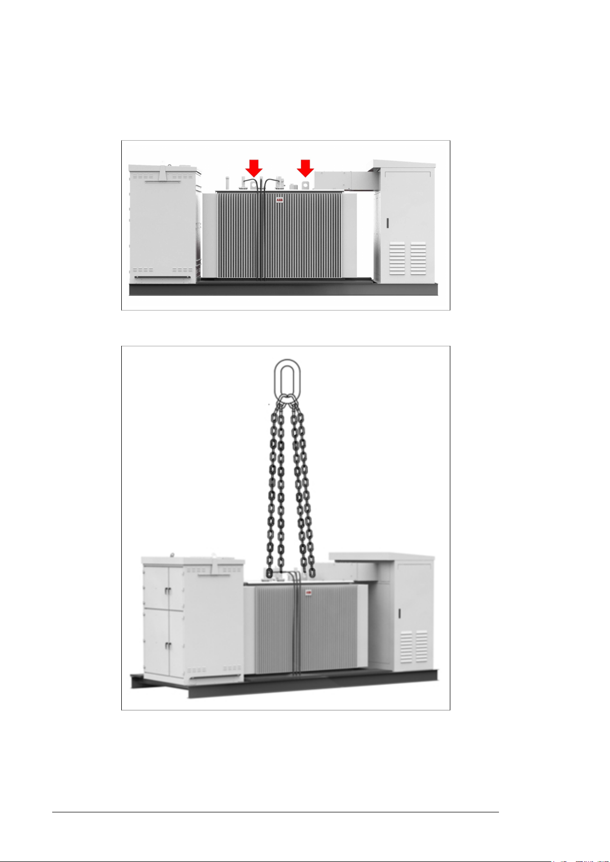
1. Attach four slings to the fastening points (lifting lungs) located in the roof of the MV
transformer. See the locations marked in below figure.
2. Connect the slings to the crane as shown in below figure.
Page 33
Storing, lifting and transporting 33
Transporting
WARNING!
Keep the transportation height as low as possible. Make sure the total height of
the transportation is not more than the maximum allowed height.
WARNING!
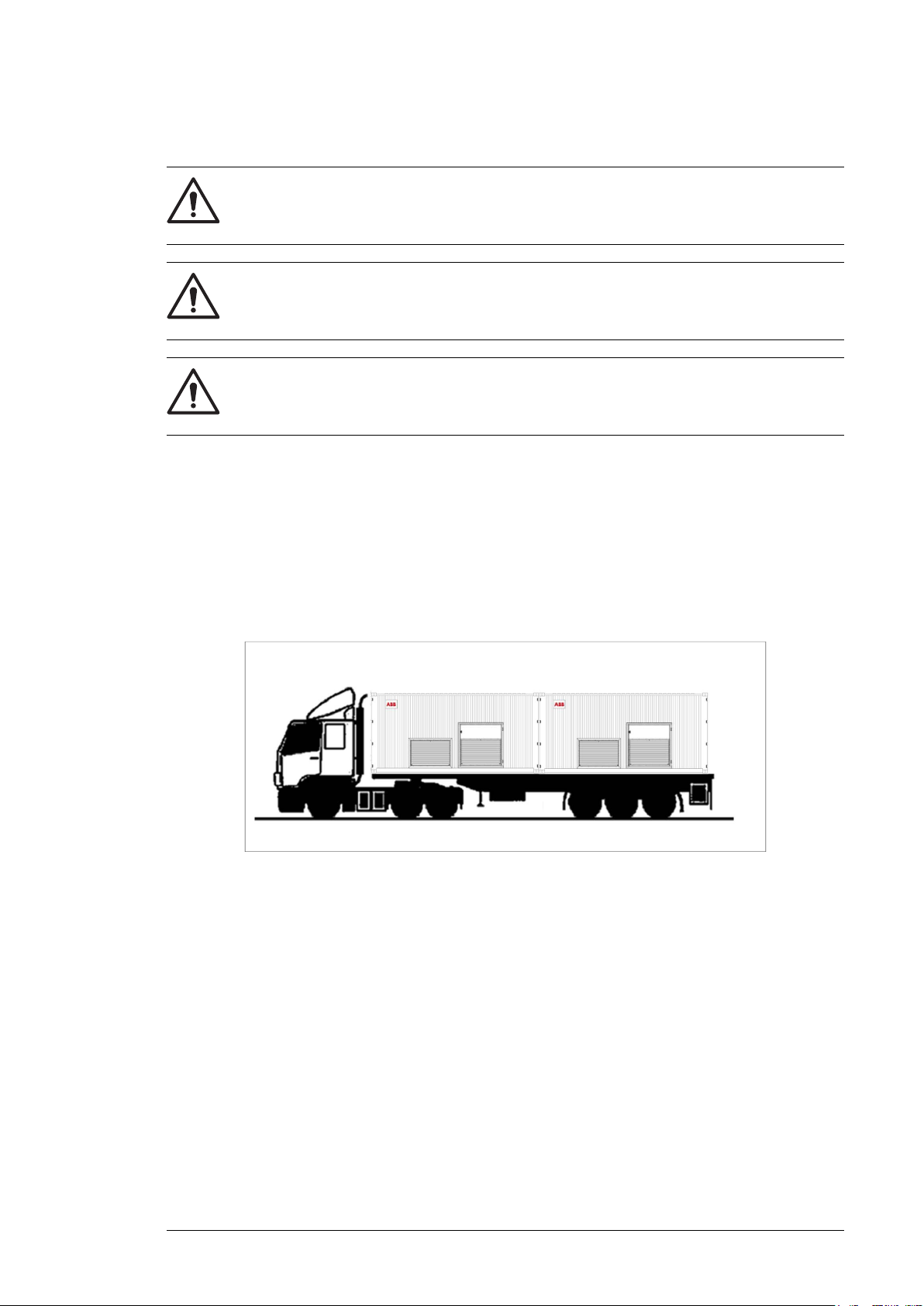
Transport the MVCS on an open heavy-duty chassis. Do not use an enclosed
trailer because the stations surface could easily be damaged.
WARNING!
Do not throw the hooks over the roof. This can damage the paint and cause
corrosion or operation problems.
Obey the following instructions:
• Protect the MVCS with wooden corners, plastic film, etc. The MVCS is delivered
unpacked from the factory as standard.
• Protect the interior of the MVCS from rainwater by using temporary protection plates
(anti-typhoon) on air intakes and outlets.
• The MVCS is built to fit inside an ISO 20 HC (1AAA according to ISO 3874) type shipping
container. It can be transported on a dedicated sea container trailer using the standard
container attachment system.
■ Incoming inspection at arrival
• Visually check for any potential transportation damage(s). If any damages found, mark
and record them and immediately inform your local ABB representative or your ABB
sales contact.
•
Repair any damaged paint. See section, Maintenance of painted surfaces (page 57).
• Check that the MVCS corresponds to the delivery list and order. Record the deviations
(if any) and immediately inform your local ABB representative or ABB sales contact.
Page 34

34 Storing, lifting and transporting
Unloading
WARNING!
To prevent damage to the MVCS, keep the delivery packaging and protection
canvas on until you install it.
WARNING!
Inspect the MVCS carefully before performing any activity. Check that there is no
protuberance or any general poor condition.
Before unloading, follow these instructions:
1. Protect the corners of the MVCS against shock.
2. Make sure that the terrain is level and sturdy. Consider that the MVCS has an
approximate weight of 11 tons.
3. Unload the standard container carrying the MVCS inside. Follow local regulations and
applicable standards.
4. Remove all stops, and transportation slings at both ends and laterals.
■ Tools used for unloading
• Five tons forklift
• Two guide platforms with length 5 m and width 500 mm
• Two belly chains of eight tons
• Two slings of eight tons. Minimum five meters.
Page 35
Storing, lifting and transporting 35
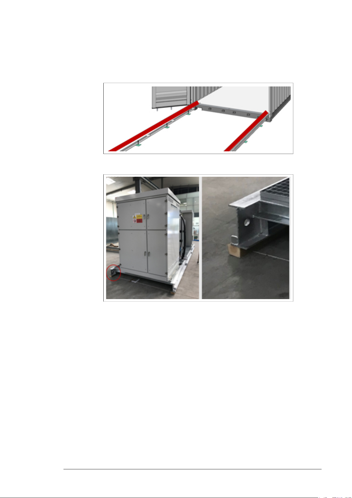
■ Unloading instructions
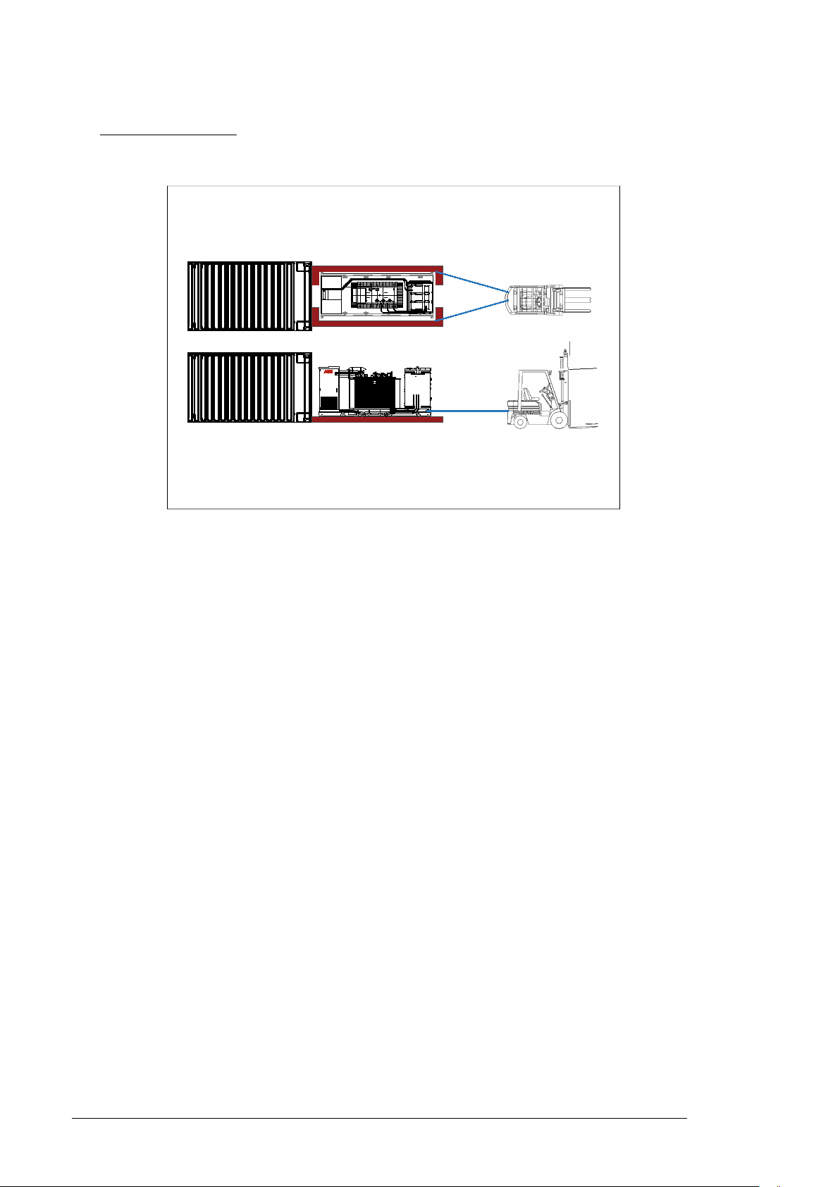
1. Align the guide platforms to the wheels trajectory.
2. Make sure that the guide platforms are leveled to the container floor.
3. Connect the belly chains to the fastening points in the skid profile.
4. Connect the slings to the belly chains and to the forklift.
Page 36
Aux. Breakers and others
1W
Ø200
152
36 Storing, lifting and transporting
5. Slowly and carefully pull the MVCS out of the container using the forklift. The forklift
must be perfectly aligned to the MVCS, so that the station does not touch the container
walls.
Optional: Pull the MVCS until connection with spreader and crane is possible. Then
follow the lifting procedure to place the MVCS.
Page 37

Mechanical installation
Mechanical installation 37
5
Contents of this chapter
This chapter describes the mechanical installation of the PVS-100/120 medium voltage
compact skid (MVCS) and gives instructions on how to select the location and guidelines
to build the foundation for the MVCS. Always obey the local regulations.
Safety
See Safety instructions (page 9).
Before you move the MVCS, see instructions in chapter Storing, lifting and
transporting (page 29).
Tools
Use the following tools to move the MVCS, to fasten the MVCS foundation, and to tighten
the connections:
• Crane, forklift, or pallet truck (with sufficient load capacity)
• Pozidriv and Torx (2.5 to 6 mm) screwdrivers with short and long heads or bits
• Torque wrench
• Set of wrenches and sockets.
Foundation guidelines
For information on the MVCS dimensions and footprint, see drawing
3AES-PVS-100_120-MVCS-30-DW02.
Always follow the local rules and laws when designing and constructing the foundation. Pay
attention to the proper planning and constructing of the foundation. For example, an improper
foundation can cause settling of the MVCS or difficulty opening the door.
Page 38
38 Mechanical installation
Follow the below guidelines:
• To prevent any risk of corrosion, install the MVCS higher than its surroundings so that
surface water will not collect around its perimeter.
• Tilt the surface of the surrounding ground at least 50 mm per meter (two inches per 40
in). This ensures that surface water flows away from the MVCS.
• Consider local conditions, such as soil type, frost protection, rain amounts, etc. There
needs to be at least 300 + 200 mm gravel under the foundation.
• Consider the required cable bending radius and installation room.
• The built-on site user platform around the MVCS must be at least one meter (40 in)
wide. If it is narrower, service work can be difficult.
• The entire perimeter of the MVCS must rest on the foundation.
• Check the load carrying capacity of the ground and potential local special requirements
(for example, earthquake or typhoon anchoring) of the construction area. Use materials
suitable for the local conditions and requirements.
Placing the MVCS on the foundation
WARNING!
Before lifting the MVCS onto the foundation, make sure the foundation is aligned
well, hardened and stable.
1. Measure the level of the foundation and the tilting of the surface of the surrounding
ground around the foundation. Obey the Foundation guidelines (page 37).
2. Make sure the foundation below the MVCS is leveled. Inclination up to 0.1 degrees is
permitted.
3.
Lift the MVCS onto the foundation. Obey the instructions in section Lifting (page 31).
Make sure that the foundation does not move. Also make sure that the station is stable
and in direct contact with the foundation.
4. When the MVCS is placed on the foundation, measure the height and inclination of the
MVCS. Check the slope of the surface of the surrounding ground around the MVCS.
Page 39
Mechanical installation 39
Fastening the MVCS
WARNING!
Do not fasten the MVCS by electric welding, because the welding circuit can
damage electronic circuits and integrity of the station. ABB does not assume any
liability for damages caused by electric welding.
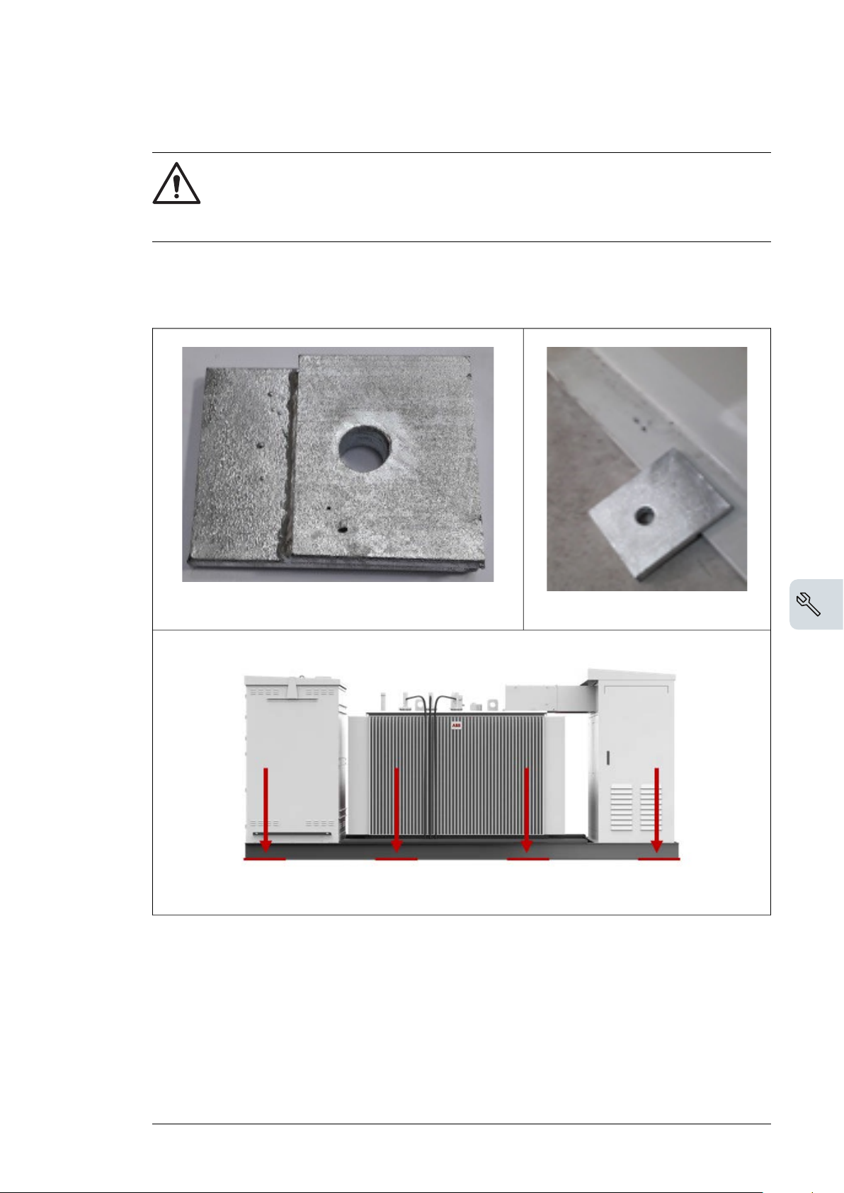
To fasten the MVCS to the foundation, bolt the cabinet through the holes on the base of the
inverter or use the supplied attachment brackets (see figure below). Use bolts and washers
in each connection point.
Attachment bracket
Fastening points
Follow the local regulations and applicable standard to calculate the mechanical connections
and structural properties. Always consider the site conditions and terrain characteristics.
For more information, see drawing 3AES-PVS-100/120-MVCS-30-DW02.
Placement of bracket
Constructing earthing electrode and earthing
Construct an earthing electrode for the MVCS according to the local regulations. For more
information, see drawing 3AES-PVS-100/120-MVCS-02-DW02.
Page 40

40 Mechanical installation
Filling the pit and finalizing the surroundings
1. If required for local frost conditions, add insulation around the column foundation.
2. To minimize the growth of grass, use geotextile below the foundation and below the
service platform around the MVCS. Put the geotextile 20 cm (8 in) below and about 100
cm (40 in) around the foundation.
3. The MVCS is a not walking station, it is designed to be operated from the outside.
Provide a permanent or portable platform for comfortable operation of the MVCS
switching devices as the foundation can be higher than the surrounding ground. For
platform design and construction, follow the local rules and standards.
4. Do not plant trees near the MVCS. If bushes are planted, make sure that the planting
compost base is at least one meter (40 in) away from the station housing and that the
fully-grown bushes do not prevent maintenance access to the MVCS. Make sure that
anything planted near the inverter does not discharge dust or seeds that can affect the
cooling air flow.
Page 41
Electrical installation
Electrical installation 41
6
Contents of this chapter
This chapter contains general instructions for earthing and cabling the PVS-100/120 medium
voltage compact skid (MVCS). Obey all instructions contained in the applicable documentation
(such as other hardware manuals) and the local regulations.
WARNING!
Only an authorized electrician is allowed to install the cabling to the MVCS. Obey
the Safety instructions (page 9) and the local safety regulations. If ignored,
physical injury or death may follow, or damage to the equipment may occur.
WARNING!
Do not do any electrical installation work during a thunderstorm.
WARNING!
Make sure that all external cable entries are fully sealed to prevent entry of foreign
elements, such as animals and insects.
Page 42

42 Electrical installation
Routing the cables
When you route the cables:
• Install the AC power cables and the control cables on separate routes.
• Use metallic screen cables for control cables.
• Do not put extra cables through the MVCS without permission.
For more information, see drawing 3AES-PVS-100_120-MVCS-01-DW02.
Earthing
Always construct an earthing electrode for the MVCS. Always follow the local regulations.
Follow the minimum requirements for the earthing electrode:
• Minimum cross-sectional area = 95 mm2. The plates are prepared for 95 mm2cables
• Installation depth = 500...800 mm from the surface of the soil
• Installation route around the MVCS = one meter from the outer wall
• Connect the MVCS earthing busbar and the station enclosure to the earthing electrode.
Use joint lubricant to protect the connection point against corrosion
For more information, see grounding drawing 3AES-PVS-100_120-MVCS-02-DW02.
Protective earthing (grounding) inside the MVCS
The protective earth (PE) terminals or frames of all the main components in the MVCS are
connected to two main PE busbars located inside the station.
At the installation site:
• measure the continuity of all internal PE connections by measuring the conductivity
between each protective earth terminal and the main PE busbar.
• earth the shields, armors and protective conductors of all incoming cables to the
appropriate earthing terminals of the station.
For more information, see the grounding layout drawing
3AES-PVS-100/120-MVCS-02-DW02.
Measuring the insulation resistance of the cabling
Make sure that the insulation resistance of the external power cables are measured according
to manufacturer recommendations and local regulations.
Page 43
Electrical installation 43
Connecting the inverter inputs
Connect all inverter power cables in the AC cabinet. See details of station type and
corresponding inverter type in below table.
Inverter typeStation type
PVS-100PVS-100-MVCS
PVS-120PVS-120-MVCS
To connect the inverter inputs, follow the instructions below:
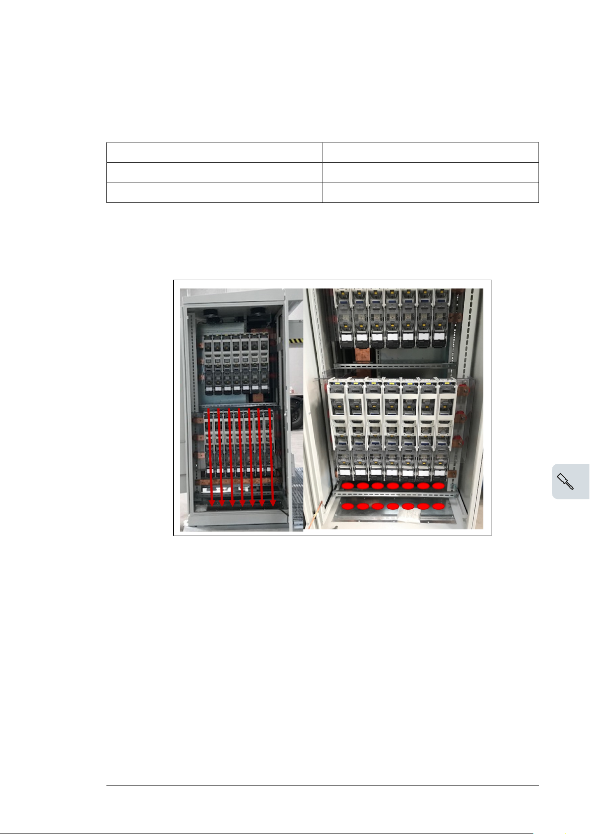
1. Make sure that all cables have the maximum cable size = 185 mm2.
2. Considering the AC cable sizes and that the cables must be aligned with the fuse bases,
mark the LV AC lead through holes in the cable cover:
3. Remove the cable entry covers.
Page 44
44 Electrical installation
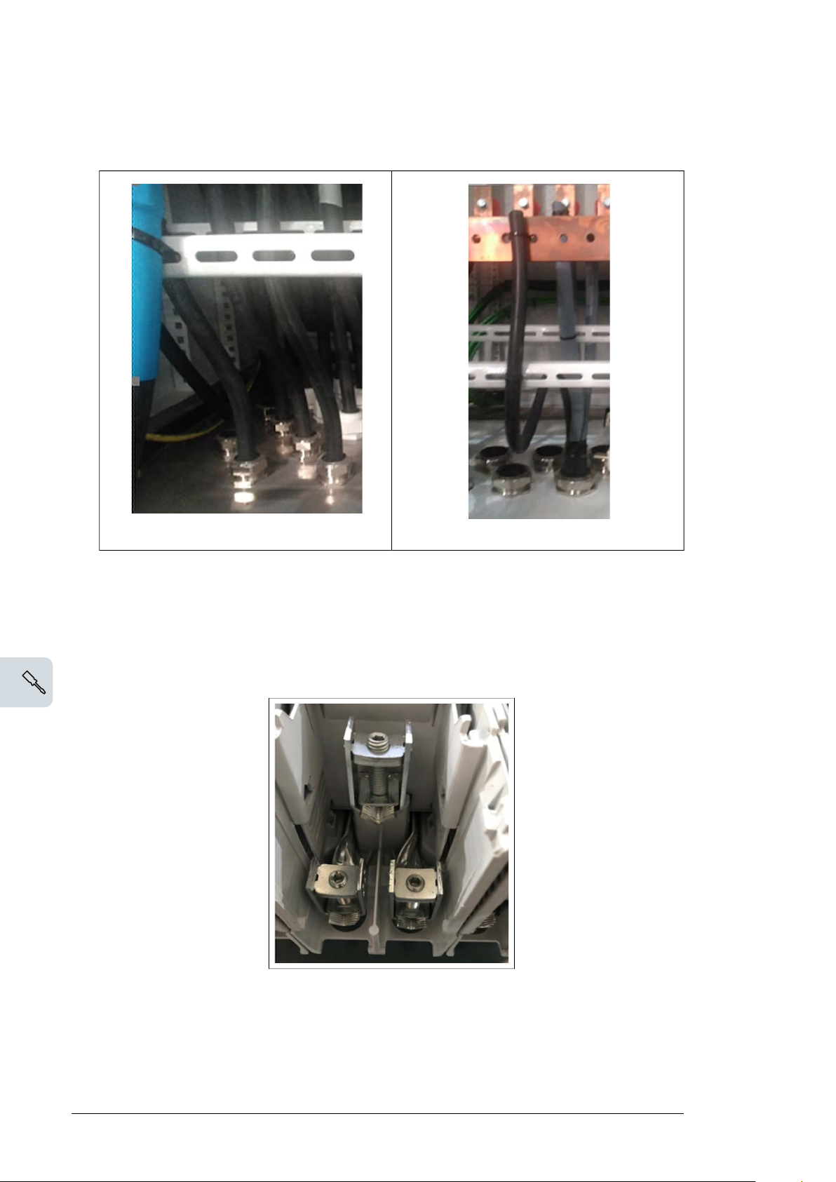
4. Drill holes of appropriate sizes in the AC cabinet cover and install cable glands to ensure
that IP protection is established.
Individual cabling (single phase)
Multicore cabling (3-phase)
5. Route the cables inside the AC cabinet.
6. Connect the cables to the correct fuse base terminals in the AC cabinet. Tighten the
connections.
Note:
You can connect the fuse base without terminating the LV AC cables.
Page 45
Electrical installation 45
Connecting the communication and auxiliary cabling (Optional)
See the following drawings:
• Auxiliary cabinet drawing—3AES-PVS-100/120-MVCS-14-DW03
• Communication cabinet drawing—3AES-PVS-100/120-MVCS-15-SL01
• UPS connection drawing—3AES-PVS-100/120-MVCS-16-SP01.
To connect the cabling for auxiliary cabinet, communication and UPS:
1. Remove the cable entry covers.
2. Considering the auxiliary cable sizes and their alignment, drill holes of appropriate sizes
in the cable covers.
3. Install cable glands to ensure that IP protection is established.
4. Lead the cables into the station.
5. Connect the cables to the correct terminal blocks (communication board and auxiliary
service board). Tighten the connections.
6.
Fill the cable trenches and seal the cable entries. See chapter Finalizing the
installation (page 47).
Connecting the power grid cabling to the MV switchgear
See the MV switchgear manual and the wiring diagrams that is delivered with the MVCS.
1. Remove the cable entry covers.
2. Lead the cables into the MVCS and seal the cable entries.
3. Terminate the cables according to the cable manufacturer instructions. Connect the
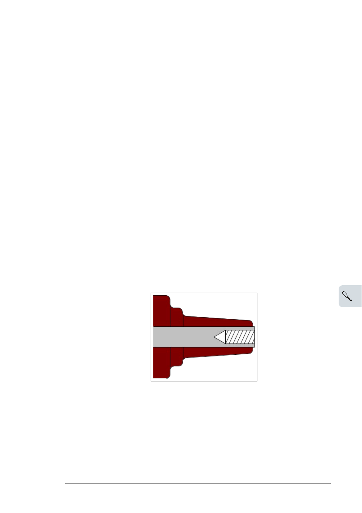
cables to the MV switchgear. The standard cable termination (see figure below) installed
in MV switchgear is of interface type C with bolted type 400 series.
Interface C with M16 x 2 metric threads
400 series, In= 630 A
This termination is standard on all modules and for side connections.
Page 46

46 Electrical installation
4. Fill the cable trenches and seal the cable entries. For more information, see chapter
Finalizing the installation (page 47).
5. Connect the cables to correct terminals.
Maximum MV cable sizes depend on the connector dimensions. See MV switchgear manual
to determine the maximum cable size and configuration (see 1YVA000024 and 1YVA000026).
Page 47
Finalizing the installation
Finalizing the installation 47
7
Contents of this chapter
This chapter describes how to finalize and check the installation of the PVS-100/120 medium
voltage compact skid (MVCS). Obey all local regulations.
WARNING!
Only an authorized electrician is permitted to install the cabling to the MVCS. Obey
the Safety instructions (page 9), and the local safety regulations. If ignored,
physical injury or death may occur, or cause damage to the equipment.
WARNING!
Do not do electrical installation work during a thunderstorm.
WARNING!
Make sure that all external cable entries are fully sealed to prevent entry of foreign
elements, such as animals and insects.
Finalizing the installation
• Clean the MVCS of all dirt.
•
Repair any damages to the paint surface. See section, Maintenance of painted
surfaces (page 57).
• If not yet done, seal the cable entries, cover the cable entries with sand and sprinkle a
handful of cement over the sand. The cement hardens in a few days and it forms a
barrier against small animals and plant growth.
Page 48
48 Finalizing the installation
Landscaping the station
You can plant suitable bushes around the MVCS to landscape it.
Do not plant trees near the station. If bushes are planted, make sure that the planting
compost base is at least two meters away from the MVCS, and that the fully- grown bushes
will not prevent maintenance access. Make sure that the plantation does not discharge dust
or seeds that could hinder the cooling air flow.
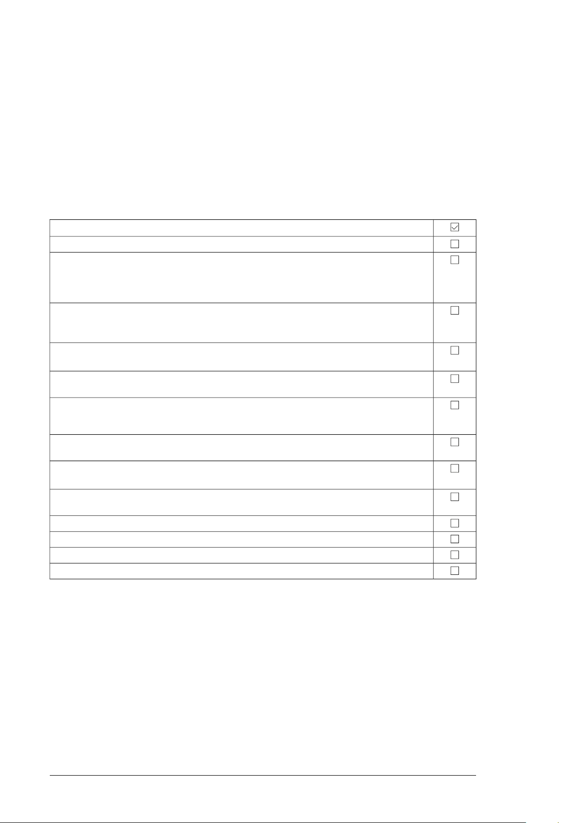
Checking the installation of MVCS
Item
Check all mechanical operating functions by operating them twice.
Examine that all cable connections are correctly tightened.
Note: Tighten the cable connections of the Switchgear to the MV transformer's bushings. These
are delivered loose to prevent damages when transporting the unit
Make sure that the MVCS clearance space is maintained.
For more information on the required clearance space, see footprint layout
3AES-PVS-100/120-MVCS-30-DW02.
Examine the paint surface and repair if any damages found. See instructions in section Maintenance
of painted surfaces (page 57).
Make sure that all cable glands at each cable inlet is installed correctly and all the unused cable
openings have protection caps.
Examine the earthing (grounding) of the MVCS and its components and make sure that it obeys
the earthing (grounding) schematic. Pull the earthing wires at the terminals to ensure that the
connections are tight.
Remove any foreign objects such as loose fastenings and tools from the MVCS. This can cause
short-circuit faults or other damages.
Make sure that the MVCS is clean. Contaminated surfaces can increase the risk of corrosion. For
more information, see chapter Maintenance (page 53).
Examine the clearance distances, cable terminations and connections and make sure that all connections are according to the main circuit diagram.
Make sure that the required warning labels are attached to the MVCS.
Make sure that the insulation resistance of the external power cables are measured.
Do the installation checks detailed in the device-specific manuals.
Do the inspection procedures required by the respective authorities.
Page 49
Start-up and operation
Start-up and operation 49
8
Contents of this chapter
This chapter describes the start-up procedure of the PVS-100/120 medium voltage compact
skid (MVCS) and the general operation criteria.
WARNING!
Only an authorized electrician is permitted to install the cabling to the MVCS. Obey
the Safety instructions (page 9) and the local safety regulations. If ignored,
physical injury or death, or damage to the equipment may occur.
WARNING!
Do not do electrical installation work during a thunderstorm.
Tools needed
• Voltage detector
•
Insulation resistance meter. For more information, see section Measuring the insulation
resistance of the cabling (page 42).
• Personal protective equipment
Prerequisite
WARNING!
Use original silica gel bags only during transport. Install new silica gel bags for
storage.
1. Remove the transportation covers.
Page 50
50 Start-up and operation
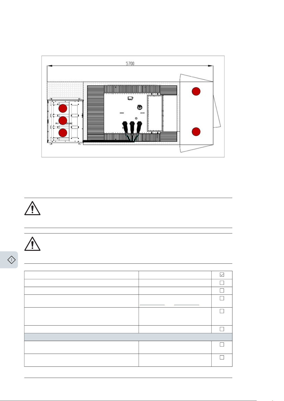
2. Remove silica gels.
See below figure. The locations of silica gels are marked red in color
Start-up procedure
This section describes the procedure to startup the PVS-100/120 medium voltage compact
skid (MVCS).
WARNING!
Only an authorized electrician is permitted to install and perform the start-up
procedure. Obey the Safety instructions (page 9) and the local safety regulations.
If ignored, physical injury or death, or damage to the equipment may occur.
WARNING!
Read the manuals and start-up procedures of all other components (inverters,
UPS, etc.). Note that the guidelines specified in this section does not replace the
instructions given by the product manuals of each component.
Additional informationTask
Check that there is no voltage.Pre-check the MV switchgear.
Visually examine the gas level of the MV switchgear.
Finalize the installation and start-up procedure of the MV
switchgear.
Finalize the installation and start-up of MV transformer.
Connecting the MVCS to power grid
Make sure all switches, fuses and breakers of the AC cabinet
are open.
Make sure that all fuse ratings are appropriate for the cable
section and plant security scheme.
See MV switchgear manual
1YVA000024 and 1YVA000026.
Follow the pre-check instructions in
the MV transformer manual that is
delivered along with the MVCS.
See inverter's manual.Finalize the installation and start-up of the inverters.
Page 51
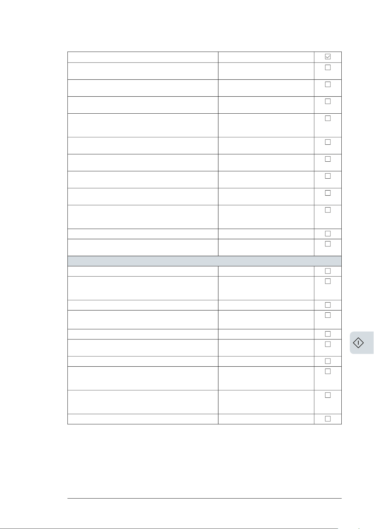
Make sure that the main switch of the Auxiliary service
transformer is opened.
Make sure that all the local regulations, applicable laws, and
standard are met.
Turn the earthing switch on the grid side of the MV switchgear
to the “not earthed” position.
Ask the power grid owner to connect the station to the power
grid. Wait until the station is connected to the power grid
before proceeding.
Turn the disconnecting switch on the grid side of the MV
switchgear to Closed position.
Turn the earthing switch on the MV Transformer side of the
MV switchgear to the “not earthed” position.
Turn the disconnecting switch on the MV transformer side
of the MV switchgear to the closed position.
Close the main breaker of the MV transformer.
Make sure that the voltage level on the low voltage side of
the MV transformer is correct. Adjust the MV transformer tap
settings if needed.
the temperature, listen to audible changes, etc.
Connecting the AC cabinet
De-energize the MV transformer.
Close the main switch of the Auxiliary service transformer.
Energize the MV transformer.
voltage AC output.
Close the Auxiliary service transformer primary breaker.
winding voltage level is 230/400 V.
Close the Auxiliary service transformer secondary breaker.
Close the auxiliary breakers one at a time. After closing each
breaker, check the voltage values.
time. Check each fuse base for voltage values directly in the
inverter input, before opening the next fuse base.
Start-up and operation 51
Additional informationTask
Contact your local grid and MV
authority.
Applicable for C module MV
switchgear
Contact your local grid and MV
authority. Only authorized personnel
are permitted to make the connections.
Applicable for C module MV
switchgear.
Applicable for V module MV
switchgear
Applicable for V module MV
Switchgear
Applicable for V module MV
switchgear
See MV tansformer documentationRun the MV transformer with no load for several hours.
See MV transformer documentationCheck the MV transformer for any malfunctions. Observe
Also de-energize (open) all other
switches, disconnectors and breakers
of the Auxiliary service board.
PVS-100:400VCheck that the incoming voltage level is equal to inverter
PVS-120: 480V
Must be 230/400 V ±10%Check that the Auxiliary service transformer secondary
Maintain "Closed" condition for the
auxiliary service lines with load. Only
open switches/breakers with loads.
Inverters must be de-energized.Close the fuse base switches of the inverter inputs one at a
See inverter manual.
See inverter manual.Follow the inverter commissioning procedure.
If any other optional equipment is integrated into the MVCS such as UPS, communication
equipment and others, then check the equipment’s applicable documentation before executing
the start-up procedure.
Page 52

52
Page 53
Maintenance
Maintenance 53
9
Contents of this chapter
This chapter contains the preventive maintenance instructions for the PVS-100/120 medium
voltage compact skid(MVCS). The instructions are intended for certified personnel to perform
maintenance tasks.
WARNING!
Only an authorized electrician is permitted to do maintenance work on the MVCS.
Obey the Safety instructions (page 9) and follow the local safety regulations. If
ignored, physical injury or death, or damage to the equipment may occur.
WARNING!
Do not do electrical work during a thunderstorm.
Tools list
• Torx drivers
• Philips screwdrivers (PoziDriv)
• Torque wrench
• Set of wrenches and sockets
• Cable and wire strippers
• Crimping tool and cable lugs
• Voltage detector
• Personal protective equipment
Page 54

54 Maintenance
Tightening torque
Use the torque values given in the table, unless otherwise specified.
Electrical connections
Torque
Bolt and nuts
Brass (N.m)Steel: A2-70/A4-70/8.8 (N.m)
-0.9M3
-2.3M4
-4.5M5
5.08.0M6
1220M8
2540M10
4070M12
60110M14
Bolt and nuts
Mechanical connection
90170M16
120240M18
1)
Torque
A2-70/A4-70Quality 8.8
0.851.21M3
0.802.78M4
1.605.5M5
2.809.5M6
6.823M8
1446M10
2479M12
37127M14
56198M16
1)
Not applicable to threaded inserts
81283M18
114402M20
Page 55

Threaded inserts
Maintenance 55
Bolt and nuts
Torque in N.m
(steel/ stainless steel)
7.9M5
12M6
20M8
34M10
Maintenance intervals
The maintenance and component replacement intervals are based on the specified
operational and environmental conditions.
ABB establishes the following as a minimum maintenance schedule. The MVCS final
maintenance schedule must be adapted and defined by the maintenance responsible of
the plant according to the site conditions, operations and others.
DescriptionAction
Visually inspect and perform maintenance if it is necessary.I
On-site/off-site performance work (commissioning, tests, measurements, etc.)P
Replace the component.R
For more information on maintenance, contact your local ABB service representative.
■ Maintenance activities
Perform the following inspections at least once in every six months.
TaskAction
Check the operating environment, surroundings and conditions.I
Check the availability of spare parts.I
Check for any dust, corrosion, etc. inside and outside the MVCS.I
Check and clean the inlet and outlet grills & filters.I
Check the sealing of all cable entries to ensure that the IP protection level is maintained.I
Clean the filters of the air inlet and outlet.I
Examine the tightness and cleanliness of the main circuit terminals and earth connections.I
Inspect the general conditions of the MVCS (door sealing, cooling fan operation, etc.)I
Inspect the operation of locks, hinges, and gaskets.I
Check that all labels are readable and in proper conditions.I
Examine the condition of the foundation.I
I
Check the maintenance activities of each component in its respective user manual (MV
Transformer, MV Switchgear, AASS Transformer etc) .
Page 56
56 Maintenance
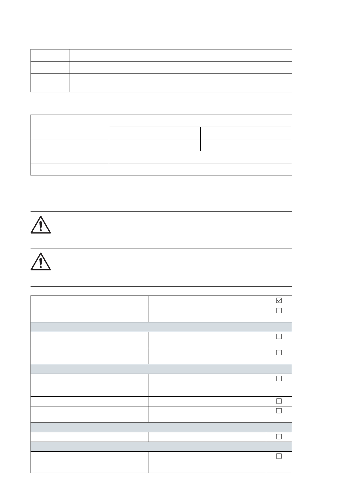
TaskAction
Inspect the temperature and operating conditions of the AC Cabinet using thermography .I
I
Examine the grounding system conductivity. This must be done in accordance to local regulation and standards.
■ Maintenance intervals
Years from start-up or intervalComponent
2010
RRCooling fans
R (every six months)Air filters
Obey manufacturer instructionsUPS
Cleaning procedure
Perform the following inspections at least once in every six months.
WARNING!
Obey the Safety instructions (page 9) and the local safety regulations. If ignored,
physical injury or death, or damage to the equipment may occur.
WARNING!
Read the manuals of other components (inverters, UPS, etc.). The guideline
specified in this section does not replace the instructions given by the product
manuals of each component.
Pre-check that there are safe conditions before
starting any cleaning procedure.
Cleaning the MVCS
Use pressurized air to clean the external
enclosure, floors. and gutters.
Use pressurized air to clean all air inlets and
outlets including grills.
Cleaning the AC Cabinet
Use a vacuum cleaner to clean the floor, doors
and interior beams.
Remove dust from the air inlets and outlets.
Use pressurized air to clean locations with
excessive dust, including busbar connections.
Cleaning the inverters
Follow the instructions in the inverters manual.
Cleaning the MV transformer area
the MV transformer surface and locations with
excessive dust.
Additional informationTask
If necessary, use a duster or pressurized air to
clean locations you cannot reach with the vacuum
cleaner.
See MV transformer manual.Use a pressurized air to clean the general dust in
Page 57
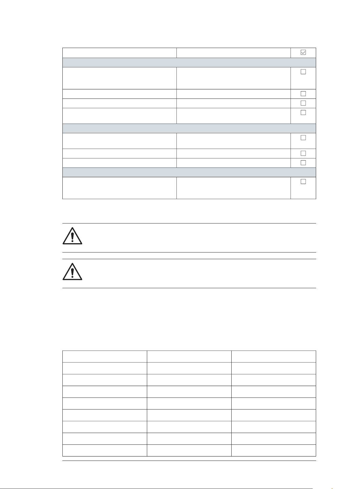
Cleaning the air filters
Clean the air filters by blowing compressed air
from the inside to the outside through the filter
until the dust comes off.
Loosen and remove the screws on the filter frame.
Clean the grill interior with a vacuum cleaner.
Install the filter support frames and tighten the
screws.
Cleaning the fans
Turn OFF/OPEN the circuit breaker for fan.
Use compressed air to clean the fans.
Cleaning the MV switchgear area
Use a vacuum cleaner to clean the floor, doors
and interior metal beams.
Maintenance 57
Additional informationTask
Prevent the circuit breaker from turning on accidentally.
Measure to make sure that it is not energized.Disconnect the supply and signal cabling.
If necessary, use a duster or pressurized air to
clean locations you cannot reach with the vacuum
cleaner.
Maintenance of painted surfaces
WARNING!
Obey the Safety instructions (page 9) and the local safety regulations. If ignored,
physical injury or death, or damage to the equipment may occur.
WARNING!
Obey the Safety instructions (page 9), requirements and specifications of the
primer and paint manufacture.
■ Repainting the scratched areas
Tools and materials
Use the following tools and materials. If the listed tools are not available in your local market,
you can use products with similar characteristics approved by a qualified technician, and
get approval from ABB.
MakeSpecificationTool
Silver P80 Triton1 udFlap Disc
Bosch1 udGrinding machine
Ehs10 udFlexible abrasive sponges
-250 mlDegreasing sprays
Finissage, Impa1 udBody shop putties
-200 grRags or blower
-10 udDisposable gloves
Uvex Astrospec1 udSafety glasses
Page 58

58 Maintenance
MakeSpecificationTool
-2 udMasks
-2 udBrushes
Maper500 grEpoxy primer
Maper500 grAliphatic polyurethane
Painting the damaged surface (no visible rust)
If there is damage(s) to the paint surface, but no damages to the metal surface (i.e. no
visible rust), then follow these instructions:
1. Clean the damaged area first with a suitable detergent and clean water.
2. Let the surface dry completely and keep it clean.
3. Apply the first layer of paint to the damaged area. Let it dry thoroughly for at least 12
hours.
4. Apply the second layer of paint to the damaged area.
Painting the damaged surface (visible rust)
If the damage extends to the metal surface or there is visible rust:
1. Remove the rust with sandpaper/polishing disk.
2. Clean the damaged area and its surroundings using a cloth or blower.
3. If necessary, apply putty to even out the surface.
4. Coat the damaged area with an epoxy primer. Let it dry thoroughly (for at least 24 hours).
5. Apply first layer of paint to the damaged area. Let it dry thoroughly (for at least 12 hours).
6. Apply second layer of paint to the damaged area.
7. Apply final layer (e.g. Aliphatic Polyurethane coating).
■ Maintenance of Zinc coated surfaces
Pay attention to doors and lower parts of the walls. These areas have potentially corrosive
elements such as dust and humidity.
If there is damage to the zinc-coating:
1. Carefully remove any rust with sandpaper.
2. Clean the damaged area and its surroundings.
3. Coat the damaged area with the zinc coating. Use Würth Zinc 300 for a thicker coat.
On large areas, you can use Würth Zinc Spray Perfect to ease the work and to get an
even surface.
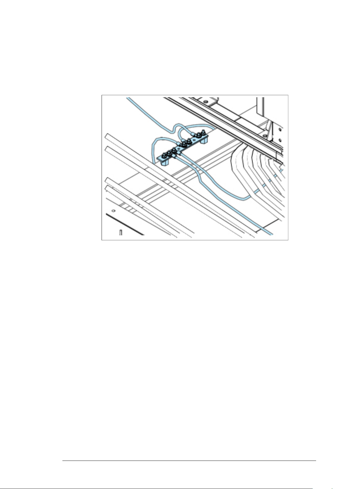
Maintenance of grounding bars and points
■ Tools
• Steel wool
• Ensto SR1 joint compound or equivalent
• 42839 Würth protective wax or equivalent
Page 59
Maintenance 59
■ Procedure
1. Examine the condition of the grounding bar and grounding cables in the MV switchgear
area. If there is any visible corrosion, remove the cables and remove the corrosion with
steel wool. Apply joint compound between the grounding bar and the joint surfaces of
the cable terminal.
2. Change the spring lock washers. Tighten the cables to the nominal torque values.
3. If corrosion is more, apply protective wax spray on the grounding bar and the cable
terminals.
Page 60

60
Page 61

Technical data
Technical data 61
10
Contents of this chapter
This chapter contains the technical data of the PVS-100/120 medium voltage compact skid
(MVCS).
Page 62
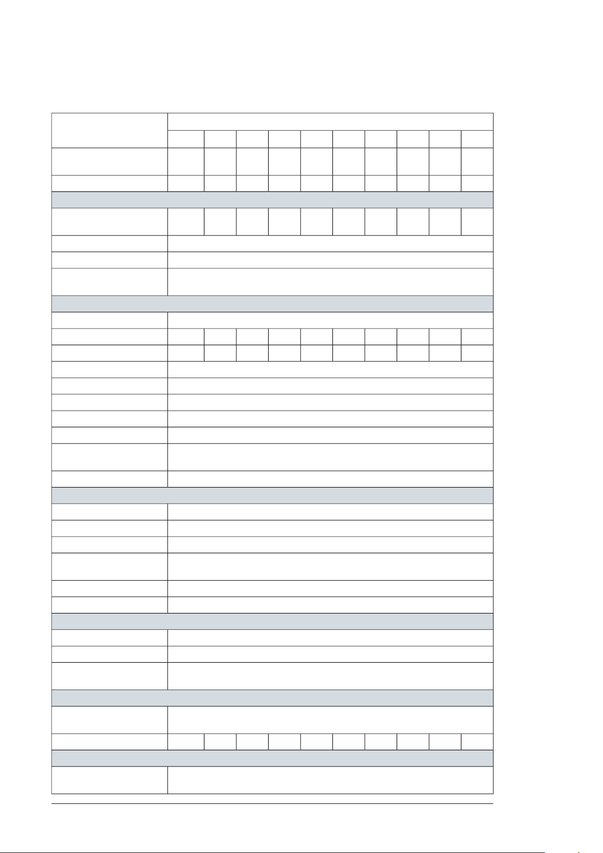
62 Technical data
Technical data and types: PVS-100 MVCS
Data
parallel
LV distribution panel
feeders
replaceable surge arrester
MV transformer
secondary)
MV switchgear
to 36 kV)
Auxiliary supply
panel for auxiliary functions
Mechanical characteristics
(L × W × H)
Environmental
range
Type code (PVS-100-TL-...
260024002200200018001600140012001000800
2624222018161412108Number of inverters in
260024002200200018001600140012001000800Maximum rating in kVA
2624222018161412108Number of fuse protected
200 AFuse rating of feeders
YesBreakable on load
Type 2 (type 1 + 2 optional)Over voltage protection -
Oil immersed (ONAN)Transformer type
260024002200200018001600140012001000800AC power at 30°C in kVA
260024002200200018001600140012001000800AC power at 40°C in kVA
400 VLow voltage level
≤ 36 kVMedium voltage level range
50 Hz or 60 HzRated frequency
Mineral (vegetable optional)Oil type
± 2 x 2.5%Tap changer
AI/ AIWinding material (primary /
YesEco efficiency optional
ABB SafePlus (SF6-insulated)Switchgear type
630 ARated current
Single (CV) or double feeder (CCV)Configuration
Circuit breaker (16 kA or 20 kA / 20 kA or 25 kA)Protection (up to 24 kV / up
ABB REJ603 (others on request)Protection relay type
YesMotorized optional
10 kVA (higher on request)Auxiliary transformer power
400 / 400-230 VAuxiliary transformer voltage
YesLow voltage distribution
5700 x 2150 x 2500 mmLength, Width, Height
9998887777Weight approx. ton
-25°C … +60°C (with derating above 40 C)Operating temperature
Page 63

Technical data 63
Data
(non-condensing)
rating
Product compliance
Type code (PVS-100-TL-...
260024002200200018001600140012001000800
≤ 2000 mOperating altitude range
≤ 95%Relative humidity
IP 54Environmental protection
C4 (C5M optimal)Painting corrosion protection
IEC 60364, IEC 61936-1, IEC 60502-1Conformity
Page 64
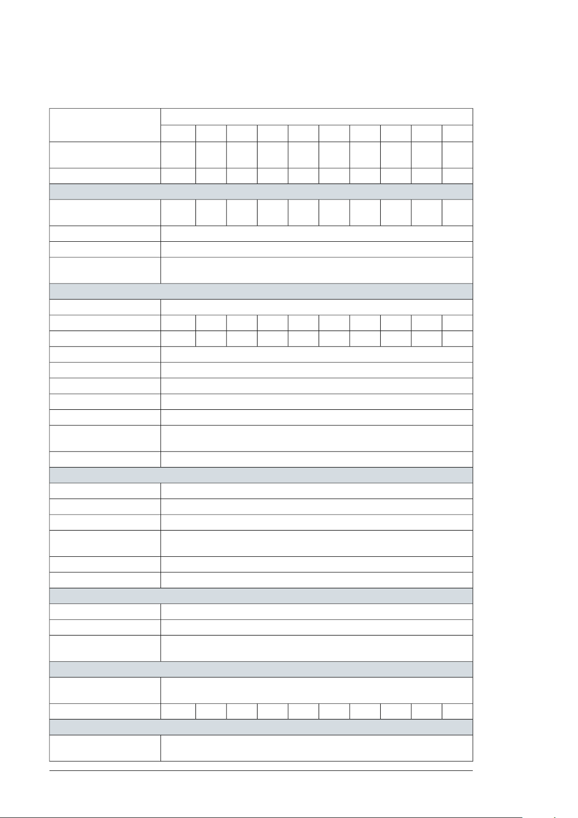
64 Technical data
Technical data and types: PVS-120 MVCS
Data
parallel
LV distribution panel
feeders
replaceable surge arrester
MV transformer
secondary)
MV switchgear
to 36 kV)
Auxiliary supply
panel for auxiliary functions
Mechanical characteristics
(L × W × H)
Environmental
range
Type code (PVS-120-TL-...
312028802640240021601920168014401200960
2624222018161412108Number of inverters in
312028802640240021601920168014401200960Maximum rating in kVA
2624222018161412108Number of fuse protected
200 AFuse rating of feeders
YesBreakable on load
Type 2 (type 1 + 2 optional)Over voltage protection -
Oil immersed (ONAN)Transformer type
312028802640240021601920168014401200960AC power at 30°C in kVA
312028802640240021601920168014401200960AC power at 40°C in kVA
480 VLow voltage level
≤ 36 kVMedium voltage level range
50 Hz or 60 HzRated frequency
Mineral (vegetable optional)Oil type
± 2 x 2.5%Tap changer
AI/ AIWinding material (primary /
YesEco efficiency optional
ABB SafePlus (SF6-insulated)Switchgear type
630 ARated current
Single (CV) or double feeder (CCV)Configuration
Circuit breaker (16 kA or 20 kA / 20 kA or 25 kA)Protection (up to 24 kV / up
ABB REJ603 (others on request)Protection relay type
YesMotorized optional
10 kVA (higher on request)Auxiliary transformer power
480 / 400-230 VAuxiliary transformer voltage
YesLow voltage distribution
5700 x 2150 x 2500 mmLength, Width, Height
111099887777Weight approx. ton
-25 C … +60 C (with derating above 40 C)Operating temperature
Page 65

Technical data 65
Data
(non-condensing)
rating
Product compliance
Type code (PVS-120-TL-...
312028802640240021601920168014401200960
≤ 2000 mOperating altitude range
≤ 95%Relative humidity
IP 54Environmental protection
C4 (C5M optimal)Painting corrosion protection
IEC 60364, IEC 61936-1, IEC 60502-1Conformity
Page 66

66
Page 67

Drawings
Drawings 67
11
Contents of this chapter
This chapter contains the technical drawings of PVS-100/120 medium voltage compact skid
(MVCS).
List of technical drawings
The list includes two types of drawings:
• Product Series—Standard product series drawings that can be consulted prior to the
purchase of the unit.
• Project Specific—Drawings specific to a project that are delivered with the unit, only on
request.
TypeDescriptionDrawing code
Product SeriesSingle Line Diagram3AES-PVS-100_120-MVCS-01-
DW01
Product SeriesElectrical Layout3AES-PVS-100_120-MVCS-02-
DW01
Product SeriesGrounding Layout3AES-PVS-100_120-MVCS-02-
DW02
Product SeriesDimensional Layout3AES-PVS-100_120-MVCS-30-
DW01
DW02
DW03
SL01
Product SeriesFootprint3AES-PVS-100_120-MVCS-30-
Project SpecificAuxiliary Cabinet3AES-PVS-100_120-MVCS-14-
Project Specific (if applicable)Communication Board3AES-PVS-100_120-MVCS-15-
Page 68

68 Drawings
SP01
TypeDescriptionDrawing code
Project Specific (if applicable)UPS Connection3AES-PVS-100_120-MVCS-16-
Page 69

—
Further information
Product and service inquiries
Address any inquiries about the product to your local ABB representative, quoting the type designation
and serial number of the unit in question. A listing of ABB sales, support and service contacts can be found
by navigating to new.abb.com/power-converters-inverters/solar.
Product training
For information on ABB product training, navigate to new.abb.com/service/training.
Providing feedback on ABB Drives manuals
Your comments on our manuals are welcome. Navigate to
new.abb.com/power-converters-inverters/document-library.
Document library on the Internet
You can find manuals and other product documents in PDF format on the Internet at
new.abb.com/power-converters-inverters/document-library
Page 70

www.abb.com/solarinverters
3AES-PVS-100/120-MVCS-00-MA01-AA
© 2019 ABB Spain. All Rights Reserved.
Specifications subject to change without notice.
3AES-PVS-100/120-MVCS-00-MA01-A Rev A (EN) EFFECTIVE 2019-05-14
 Loading...