

Data sheet
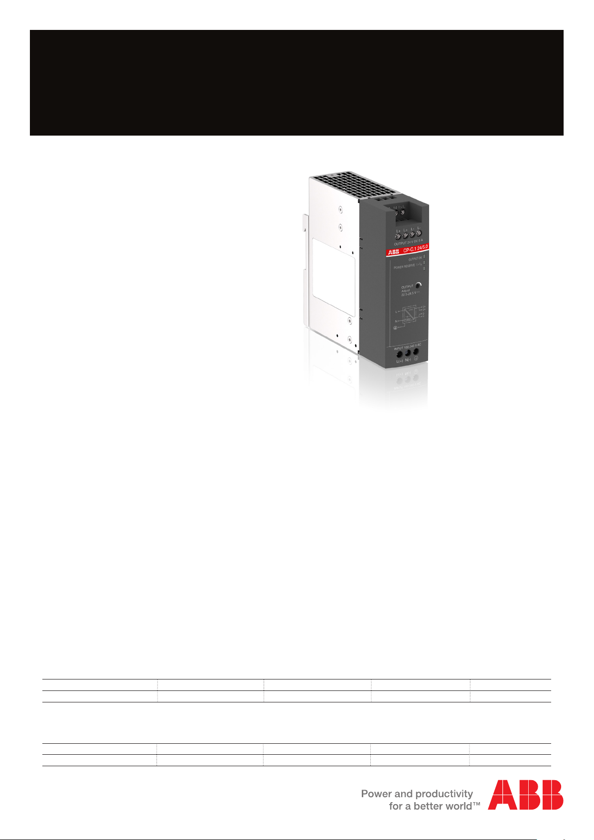
Power Supply CP-C.1 24/5.0
Primary switch mode power supplies
The CP-C.1 power supplies are ABB’s highperformance and most advanced range. With
excellent efficiency, high reliability and innovative
functionality it is prepared for the most demanding
industrial applications. The CP-C.1 24/5.0 has a
50 % integrated power reserve and operates at an
efficiency of > 92.5 %. Furthermore it is equipped
with overheat protection and active power factor
correction. This together with a broad AC and DC
input range and extensive worldwide approvals
completes the CP-C.1 as the preferred choice for
professional DC applications.
Giving the power to control.
2CDC 271 002 V0015
Characteristics
– Rated output voltage 24 V DC
– Power reserve design delivers up to 150 % at Ta ≤ 40 °C
– Output voltage adjustable via front-face rotary
potentiometer “OUTPUT Adjust”, 22.5-28.5 V
– Supply voltage range 100-240 V AC (85-264 V AC,
90-350 V DC) - approvals at DC supply valid up to
300 V DC
– Typical efficiency > 92.5 %
– Low power dissipation and low heating
– Free convection cooling (no forced cooling)
– Ambient temperature range during operation -25...+70 °C
– Open-circuit, overload and short-circuit stable
– Integrated input fuse
– Redundancy unit CP-A RU offering true redundancy,
available as accessory
– DC OK - signaling output "13-14" (Relay),
Power reserve signaling output "I > IR (Transistor)
Order data
Type Input voltage range Rated output voltage Rated output current Order code
CP-C.1 24/5.0 100-240 V AC
24 V DC
Approvals
A
H
K
Marks
a
1)
Approvals refer to rated input voltage U
1)
UL 508, CSA-C22.2 NO. 107.1
UL 60950-1, CAN/CSA C22.2 No.60950-1
SEMI F47
CB scheme: IEC 60950
CE
in
5 A 1SVR360563R1001
(pending)
(pending)
(pending)
Related products
Type Input voltage range Rated output Rated output current Order code
CP-A RU Redundancy module 10-28 V DC 24 V DC 1-40 A 1SVR427071R0000
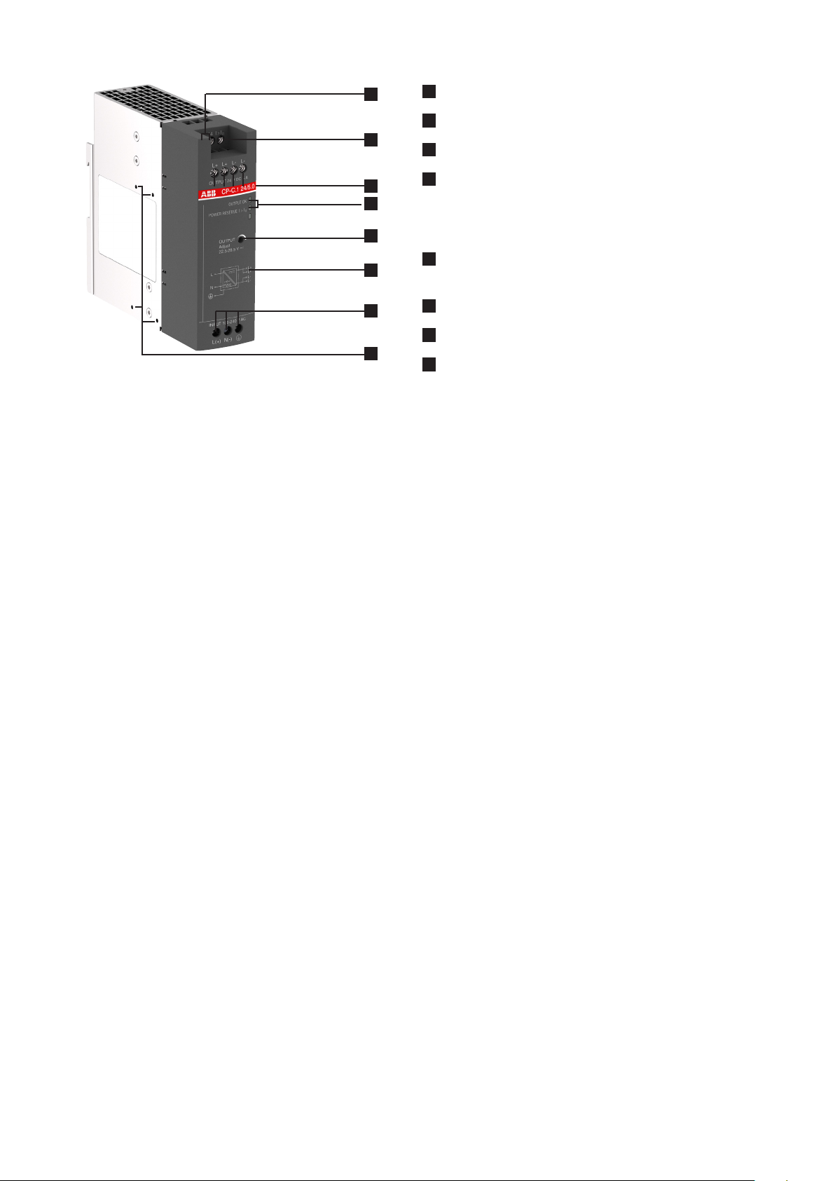
Functions
1
2
3
4
5
6
2CDC 271 002 V0015
7
8
1
13-14: DC OK Relay output
2
I > IR: Power reserve transistor output
3
OUTPUT L+, L-: Output terminals
4
Indication of operational states
OUTPUT OK: Green LED
POWER RESERVE I > IR: Yellow LED
5
OUTPUT Adjust: Rotary potentiometer -
Adjustment of output voltage 22.5 - 28.5 V DC
6
Circuit diagram
7
INPUT L(+), N(-), o /PE: Input terminals
8
Side mounting screw holes for DIN rail adapter / lateral mounting
Application
The primary switch mode power supply CP-C.1 24/5.0 has a wide range AC or DC supply input. Furthermore the
CP-C.1 24/5.0 is equipped with capacitors that ensure a hold-up time of at least 50 ms. This enables worldwide usage and
permits safe operation in fluc tuating networks and battery-powered applications.
The CP-C.1 has a robust metallic housing and a reliable construction which enables usage in harsh industrial environments.
The power reserve of up to 50 % enables trouble-free starting of heavy loads eliminating the need of usage of an oversized
power supply.
Power reserve
The primary switch mode power supply CP-C.1 is equipped with a power reserve functionality to handle the start-up of
particulary heavy loads (e.g. of a high capacitive load or a motor). To ensure that heavy loads are started up the CP-C.1
delivers up to 50 % of the nominal current to secure the operation of the application. This status is indicated by the yellow
LED giving a clear visual status of the operation mode and through the transistor output I>IR .
Signaling output
For the communication of the status of the power supply the CP-C.1 is equipped with an output relay to signal DC OK as
well as a transistor output to indicate when the power reserve is active. This signal can be used for communication to a
higher level control system e.g. a PLC.
Adjustable output voltage
The CP-C range power supplies feature a continuously adjustable output voltage of 22.5 to 28.5 V DC. Thus they can be
optimally adapted to the application, e.g. compensating the voltage drop caused by a long line length.
Data sheet | Power Supply CP-C.1 24/5.0 - 3

Status indication and signaling outputs
A
CP-C.
L+
L-
CP-C.
The CP-C.1 features integrated status indication LEDs on the front of the power supply.
1
Output OK - relay output
1
2
3
4
13
L+
max. 30 V AC, 0.5
max. 24 V DC, 1 A
(resistive load)
14
Load
1
Transistor output I>IR can be used to signal the status of the power reserve mode
2
Output relay 13-14 can be used for signaling of the status of the output voltage
3
OUTPUT OK green LED indicates status of the output voltage
4
POWER RESERVE yellow LED indicates when the power supply is in power reserve mode
2CDC 272 013 F0015
Load 20 mA
I > I
R
1
2CDC 272 014 F0015
Power reserve - transistor output
LEDs and signaling outputs
Output voltage Output OK: LED green Relay 13-14
M 22.5 V DC
< 21.5 V DC
Output current Power reserve: LED yellow Transistor I>I
V
Z
OFF ON (closed)
ImI
R
I>I
R
V
It is possible to use the messaging and signaling functionality with power supplies connected in parallel.
A parallel operation of power supplies has no influence on the function.
closed
open
R
OFF (open)
4 - Power Supply CP-C.1 24/5.0 | Data sheet

Operating mode
Parallel operation
There are two main reasons for a parallel connection of power supplies:
– Increase of power
– Fail-safety, redundancy
Up to 5 devices of the same type can be connected in parallel. For safe and reliable operation it is important to follow the
recommendations given in the following section.
Parallel connection of power supplies for increased power
If the current required by the load is higher than a single power supply can deliver, for example after the expansion of
an existing installation, an increase of the output power can be obtained by connecting power supplies in parallel. The
following prerequisites have to be fulfilled when connecting power supplies in parallel for the purpose of increased power:
– The paralleled devices must be identical.
– When connecting the power supplies in order to prevent different voltage drops on the supply lines or at the terminals
which would lead to unbalanced load at the common connection point (refer to “Current balance”) observe:
– Identical lengths of the load supply lines.
– Identical conductor cross sections of the load supply lines.
– Terminal screws have to be fastened with the same torque to guarantee equal contact resistances.
– The output voltages of the power supplies must not differ by more than 50 mV. Otherwise, safe operation is not
possible (refer to “Balancing of power supplies”).
load
+ -
-+ -+ -+ -+ -+ -+
1. CP-C.1 2. CP-C.1 3. CP-C.1
2CDC 272 002 F0015
Correct wiring for increased power
load
-+
-+ -+ -+ -+ -+ -+
2CDC 272 001 F0015
3. CP-C.12. CP-C.11. CP-C.1
2CDC 272 003 F0015
Installation for increased power Incorrect wiring for increased power
Important:
The devices must not be connected directly to each other! This could lead to an overload of the terminals since the
terminals are dimensioned for the maximum output current of a single power supply only. Always use a common connection
point!
Data sheet | Power Supply CP-C.1 24/5.0 - 5

Parallel connection of power supplies for redundancy
PE
Several power supplies are connected in parallel in order to guarantee continuous operation of the system if one power
supply fails. CP-C.1 can be used in two different redundancy modes depending on what type of redundancy is required:
– Simple redundancy, n+1
– True redundancy
Simple redundancy, n+1 redundancy
For simple or n+1 redundancy, the power supplies are connected in parallel like for the increase of capacity. To achieve
redundancy the current required by the load must not exceed the maximum output power of one single power supply (in
case of “1+1 redundancy”) or n power supplies (where n is max. 4).
It is recommended to connect the primary sides of the power supplies to different phases of the mains in order to obtain
continuous operation of the system if one phase fails.
CP-C.11. n. CP-C.1
L+ L+L- L-
I
r1
Simple redundancy or n+1 setup
I
(n-1) * I
Load
I
rn
r
2CDC 272 005 F0215
True redundancy
True redundancy gives higher system availability compared to simple or n+1 redundancy.
In a true redundancy setup the power supplies are decoupled from each other with decoupling diodes. This protects the
individual power supplies from affecting each other in case of failure of one unit or short cirucit on the secondary side or in
the wiring.
For output currents up to 40 A the ABB CP-A RU (available as an accessory) can be used.
The inputs of these units are connected to the terminals L+ and L- of the power supplies The loads are supplied directly
from the outputs of the redundancy unit.
L+ L+L- L-
CP-C.1 CP-C.1
LNPE LNPE
++--
INPUT 1INPUT 2
CP-A RU
OUTPUT
+-+-
L1
L2
L3
N
True redundancy using a CP-A RU diode decoupling unit
6 - Power Supply CP-C.1 24/5.0 | Data sheet
Load
2CDC 272 006 F0215
 Loading...