

Page 1
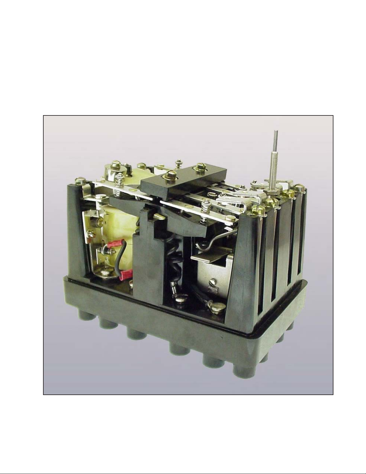
Type MG-6
Multi-Contact Auxiliary Relay
Instruction Leaet: 41-753.1 N
Effective: August 2008
Supersedes 41-753.1 M, Dated December 1999
( | ) Denotes Change Since Previous Issue
Device Number: 94X, Y, Z
Page 2

IL 41-753.1 N
Before putting relays into service, remove all
blocking materials which may have been inserted
for the purpose of securing the parts during
shipment. Make sure all moving parts operate
freely. Inspect contacts to see they are clean and
close properly. Operate the relay to check the
settings and electrical connections.
1.0 APPLICATION
The type MG-6 relay is designed for applications
where several independent circuits may be energized
or de-energized upon operation of a single primary
relay contact or where the capacity of the primary
relay contact is inadequate for the energy required. In
certain applications these relays may be used directly
as primary relays. The stationary contacts can be
reversed so that either circuit opening or circuit closing
service is readily attained. Although recommended, it
is not necessary to predetermine the relay’s contact
arrangement. If the relay has a dc operating coil, a
small increase in spring tension may be required. This
will be covered under section 6.0 ADJUSTMENTS &
MAINTENANCE.
In the usual application of the relay, the armature
resets when the operating coil is de-energized.
However, the relays can be supplied with a latching
mechanism that holds the armature in the operate
position until the latch is tripped, either by hand or
electrically.
MG-6 Multi-Contact Auxiliary Relay
mounting options as well as a choice of front or rear
terminal connections. All bases and covers are made
of a molded thermo-plastic material, which provides
a tough, insulated enclosure for the relay. MG-6 are
available as follows:
Molded Case, semi-ush mount, rear connected. •
Smart Style No’s MGA...
Molded Case, projection mount, rear connected.•
Smart Style No’s MGB...
Molded Case, surface mount, front connected •
without cover. Smart Style No’s MGC...
Molded Case, surface mount, front connected with •
cover. Smart Style No’s MGF...
Flexitest Type FT-22 Case, semi-ush mount, rear •
connected. Smart Style No’s MGD...
The MG-6 relay is an electromagnetic type solenoid
device with six independent contacts. When the coil is
energized, the armature is attracted to the lamination
stack thereby operating the moving contacts.
Operation is single mode with a make or break
function that can be supplied with either a self or a
latching reset. The duty cycle may be from extremely
intermittent to continuous energization.
MG-6 relays consist of ve major assemblies:
Operating electromagnet.1.
Armature and moving contacts.2.
Base and stationary contacts.3.
Latch (optional).4.
Coil cutoff contact (optional).5.
An operating coil cutoff contact can be supplied with
the electric reset type of relay, where an intermittent
duty coil is required for faster than normal operation
but where the operating coil circuit will be energized
continuously. An operating coil rated at 19% of supply
rating may be applied with a maximum duty of 10,000
operations (ex. 24 volt coil on a 125 volt dc circuit).
2.0 CONSTRUCTION & OPERATION
MG-6 relays are available in several different case
and cover congurations, providing users a variety of
All possible contingencies which may arise during installation, operation, or maintenance; and all details and
variations of this equipment do not purport to be covered by these instructions. If further information is desired
by purchaser regarding their particular installation or operation and maintenance of the equipment, the local
ABB representative should be contacted.
2.1 Operating Electromagnet
The operating electromagnet located at the lower end
of the relay (as shown in Figure 1) is comprised of
the operate coil (Figure 1, Item 8) and a U-shaped
lamination stack. The coil utilizes one leg of the stack
as its core. This leg is slotted at the outer end to
receive the copper lag loops used to obtain quiet ac
operation. For a dc operated coil, an iron plate, rather
than lag loops, is used to improve performance. The
inner end of the other leg of the stack is shaped so
the armature restraining spring can be attached.
2
ABB
Page 3
MG-6 Multi-Contact Auxiliary Relay
2.2 Armature and Moving Contacts
The steel armature has projecting sections at the sides
near the center, which act as knife-edge bearings
and rest on supports that are a part of the molded
base. A stud attached to the core leg of the lamination
stack extends through a hole in the lower end of the
armature. A self-locking stop-nut on the outer end of
the stud is used to limit and adjust the travel of the
armature in the de-energized direction.
The upper end of the armature has an adjustment
screw (Figure 1, Item 6) to which one end of the
armature restraining spring is attached. In both the
hand and electric reset versions of the relay, a latch
screw (Figure 1, Item 5) is mounted at the extreme
top end of the armature. For the self-reset relays, the
latch screw is replaced by a set screw which serves to
slightly separate the locking plate from the armature.
Located between the spring adjustment screw and
the latch (set) screw is a third screw, which when
tightened, applies pressure to the former screws and
effectively locks them in place.
The ac rated MG-6 relay can be used with any
combination of contacts, but the dc relay can have
IL 41-753.1 N
up to four circuit opening contacts with the normal
operating spring adjustment. With more than four
“break” contacts, the operating spring should be
adjusted to give the correct back contact follow (see
Section 6.4 CONTACTS).
The moving contact ngers are mounted on a molded
insulation plate attached to the armature. Silver
contact buttons are on both sides of the ngers so that
they may be used as either circuit-opening or circuitclosing contacts. The ngers are assembled on guide
pins between two springs so that a denite spring
compression and contact wipe is assured for either
the contact-closing or the contact-opening conditions.
Flexible leads are connected to the contact ngers.
The armature assembly has the contact ngers located
above and below the bearing points so the weight is
partially balanced about the bearings, leaving less
chance for severe shocks to move the armature. The
corresponding stationary, large silver button contacts
can be installed to mate with the moving contacts
when the armature is in either the energized or deenergized position.
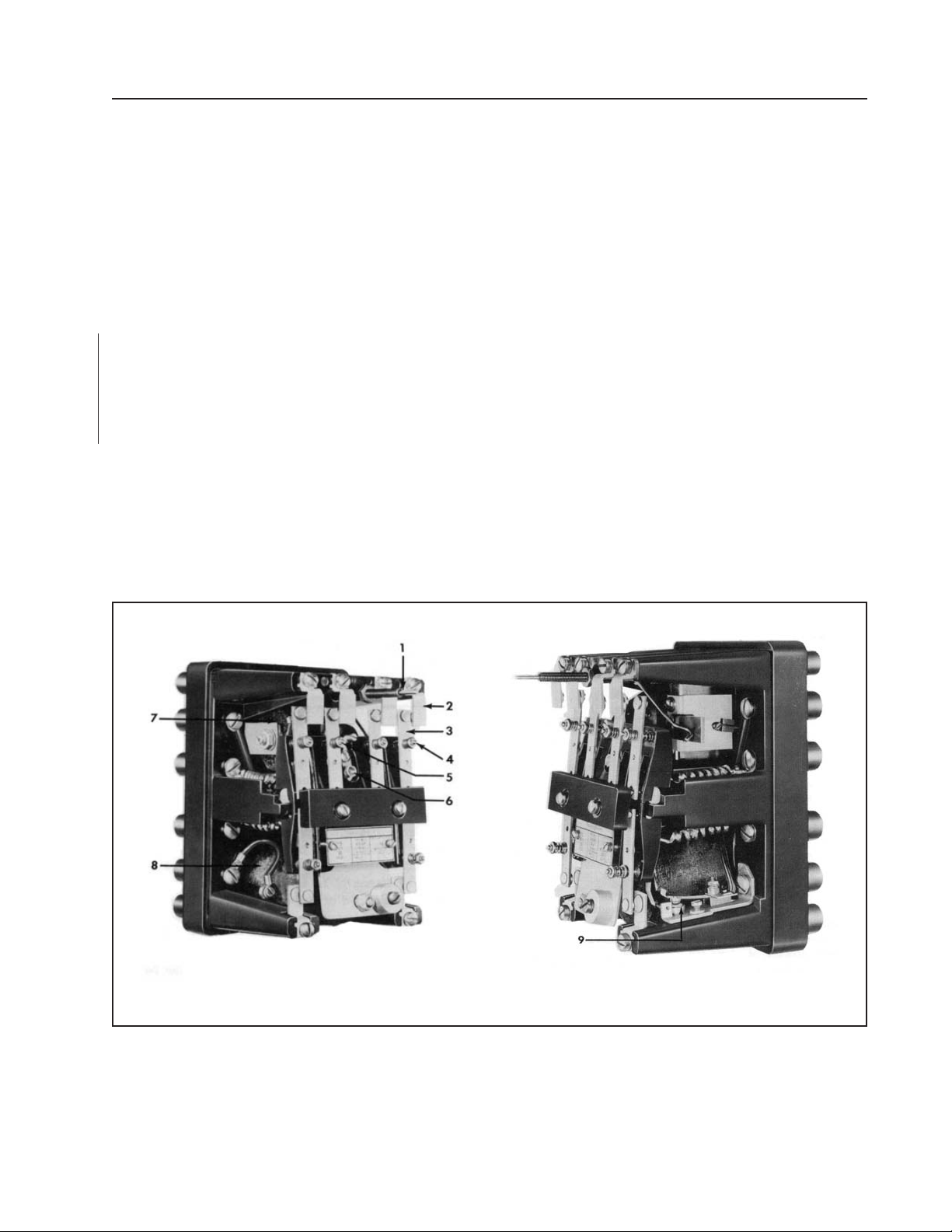
Figure 1 - Front and Side Views of MG-6 Relay with Electric & Hand Reset (Cover Removed).
1 = Reset push rod
2 = Stationary contact
3 = Moving contact
4 = Moving contact spring assembly
5 = Latch adjustment screw for armature
ABB
6 = Adjusting screw for armature spring tension
7 = Reset coil
8 = Operate coil
9 = Optional operating coil cutoff contact
3
Page 4
IL 41-753.1 N
MG-6 Multi-Contact Auxiliary Relay
2.2.1 special Contacts (make-before-break)
In certain applications of the MG-6 relay, it may
desirable to have one or more of the contacts close
before other contacts on the same relay open
(make-before-break). A special armature assembly
is required to obtain such operation and the number
of special make and break contacts desired must be
known when the relay is ordered.
The special moving contacts have longer follow than
the standard contacts and greater armature spring
tension is required for full deection of the break
contacts. Consequently, it is preferable to limit the
number of special break contacts to two. A maximum
of three may be used, although the increased armature
spring tension needed may raise the minimum pickup voltage above the standard value.
As many as ve contacts may be special make
contacts at one time, and all six contacts may be a
combination of special makes and special breaks.
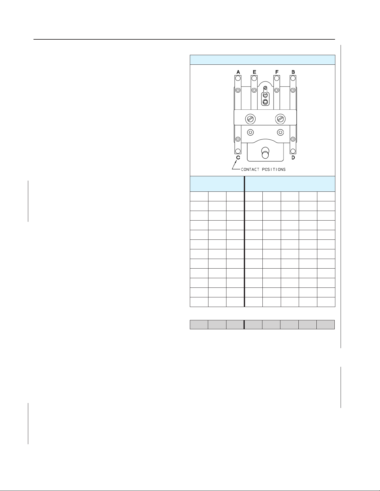
The location of the make and break contacts for all
possible combinations of these special contacts are
shown in Table 1. This table indicates the physical
location of the contacts in the relay and can be used
in conjunction with the internal schematic diagram
(for the type of case involved) to determine the
corresponding terminal locations.
2.3 Base and stationary Contacts
The stationary contacts (Figure 1, Item 2) are on six
legs located at the top and bottom of the base. The
stationary contact brackets are connected directly to
the terminal inserts by means of long screws passing
through brass tubes. This method allows a tight
connection without compressing the base material.
The contact bracket is held against its seat by
means of a spring ring which is compressed between
shoulders in the base and on the hexagonal terminal
insert.
table 1
Designated position of special Contacts
FRONT
VIEW
special “Breaks”
(max 3 allowed)
A C
A C D
A C D E
A C D E F
A B C D E F
A B C
A B C D
A B C D E
A B C D E F
A B F C
A B F C D
A B F C D E
Example:
A B C D E
Contact positions “C”, “D”, and “E” will make or close before
contact positions “A” and “B” open. The remaining (non-special)
relay contact “F” can be designated as a standard make or break.
special “Makes”
(complement Special Breaks)
2.4 Latch
The self-reset assembly is the standard build of
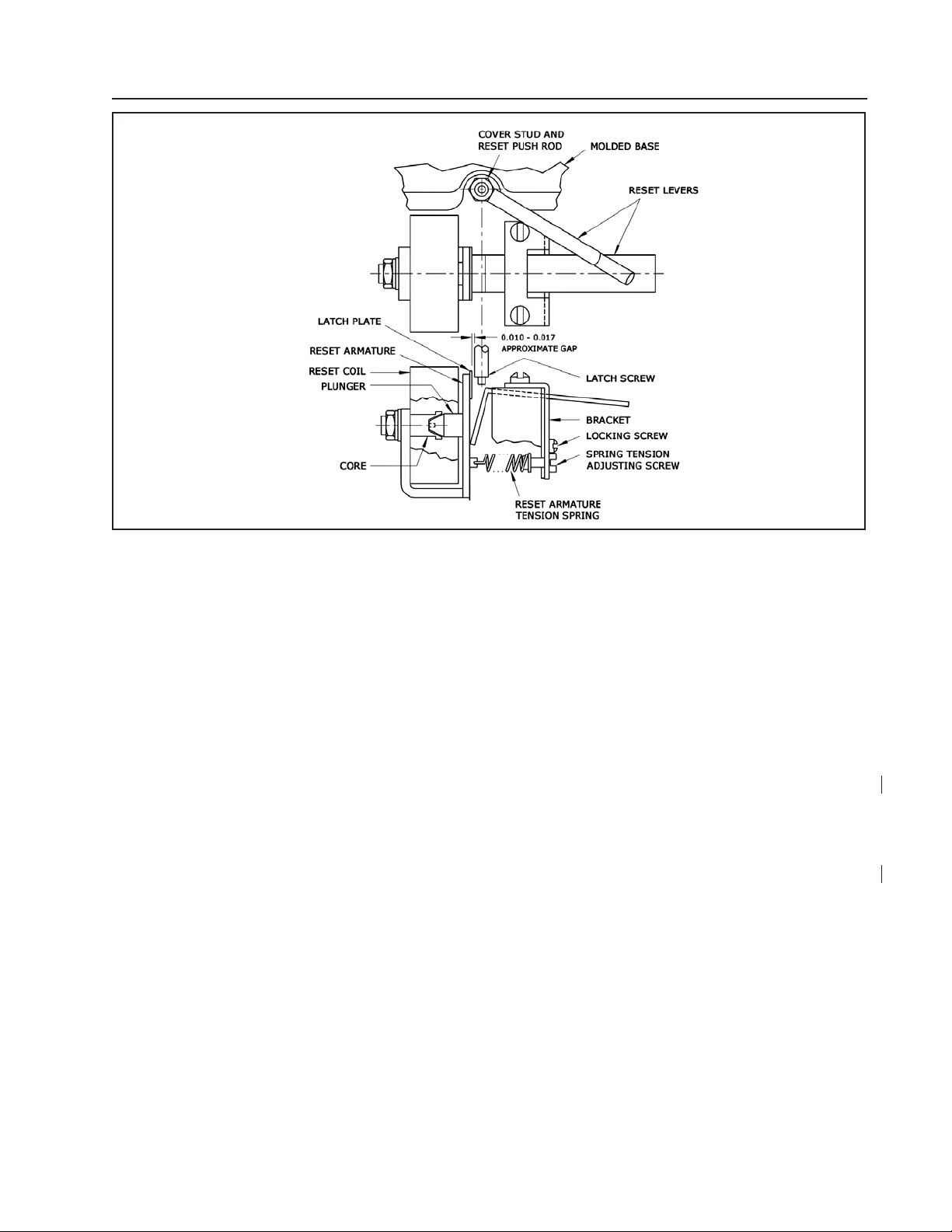
the relay. The electrical reset assembly (as shown
in. Figure 2) is optional and can be supplied in any
case conguration. The upper half of the gure
shows the reset assembly viewed from the front
of the relay. The lower half of the gure (looking in
from the bottom of the relay) shows a sectional view
of the reset assembly with the latch screw (of the
main armature) in a de-energized position. The reset
4
armature is free to be moved to the right by the reset
armature tension spring until the hardened latch plate
on the reset armature almost rests against the latch
screw. When the operating coil is energized, the latch
screw will move slightly so that its shoulder comes to
rest on the edge of the latch plate. When the reset
coil is energized, its armature moves to the left thus
permitting the main armature to return to its open
position. Pressing the reset push rod which extends
through the cover stud will also release the latch by
way of the reset lever, as shown in Figure 2.
ABB
Page 5
MG-6 Multi-Contact Auxiliary Relay
Figure 2
Detail View of Latch and Electric
Reset of MG-6 Relay
* Denotes change from previous issue.
IL 41-753.1 N
Rev. 2*
9660A79
2.5 Coil Cutoff Contact
The cutoff contact assembly (Figure 1, Item 9) is
located at the side of the operate coil and is used
to achieve a faster than normal relay operation. In
some applications of the MG-6 relay having the latch
and electrical reset, it may be desirable to have the
operating and reset coils de-energized automatically
as soon as their functions have been performed.
De-energization of the reset coil can be accomplished
by connecting the coil through one of the relay’s
“make” contacts. However, an auxiliary cutoff contact
is required to open the operating coil circuit. This
contact, when provided, is located on the lower right
side of the relay (front view) and is held in position
by the terminal screw to which the right coil lead
ordinarily connects. The coil lead is connected to the
moving contact of the cutoff contact assembly and the
end of the stationary contact bracket is in contact with
the head of the terminal screw.
The cutoff contact is closed when the main armature
is open. When the armature approaches the closed
position the spring on the molded insulation block
snaps off the roller and causes the contacts to open
and interrupt the operating coil current. When the
cutoff contact is used a weight is added at the lower
end of the armature to increase its mass and stabilize
contact action. The cutoff contact will interrupt currents
up to ve times rated coil current.
3.0 ChARACteRIstICs
Normal Operating time:
ac = approximately 0.033 seconds
dc = approximately 0.083 seconds
If faster operation is desired and if the application
requires only intermittent energization of the relay,
the operating coils may be energized at higher than
rated voltage.
Twice rated voltage will give an operating time of •
approximately 0.017 seconds on ac relays and
the coil will withstand this voltage safely for over
2 minutes if 60 Hz or 4 minutes if 25 Hz.
The time of the dc relay can be reduced to slightly •
over 0.017 seconds if the coil is energized at 5
times rated voltage. The coil will withstand this
voltage for 1 minute.
If faster time is desired on a dc relay which must be
energized continuously, the use of a low voltage coil
with a series resistor will reduce the time. With 10% of
the line voltage across the relay coil and the balance
across a series resistor, the reduced inductance of the
circuit results in an operating time of approximately
0.033 seconds. The time of operation may be reduced
to approximately 0.017 seconds by applying 4 or 5
times rated dc voltage to the coils through the coil
interrupting contact.
ABB
5
Page 6
IL 41-753.1 N
MG-6 Multi-Contact Auxiliary Relay
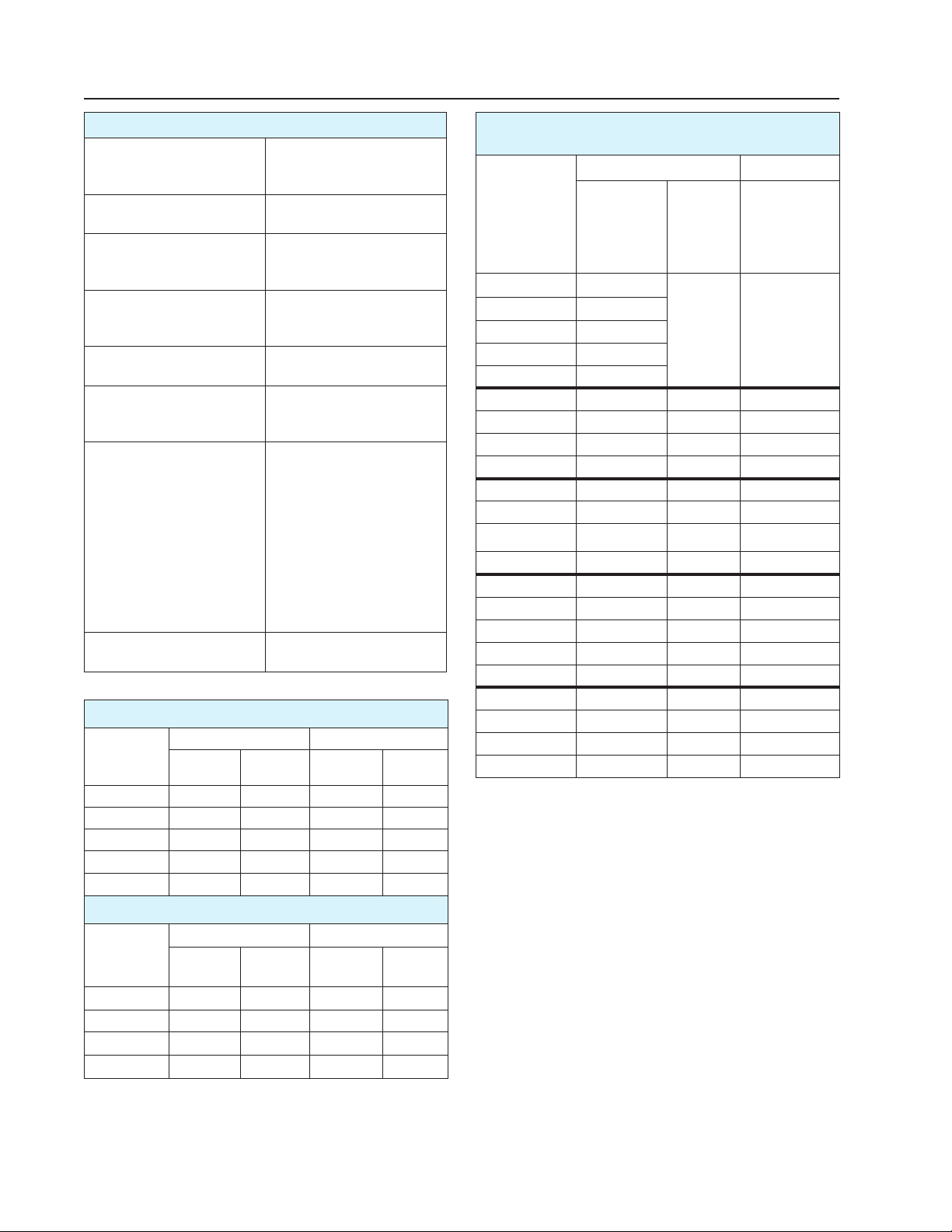
RAtINGs
standards
Meets or exceeds all the
following, as applicable
Frequency dc, 50 Hz, or 60 Hz
Dialectric Withstand 1000 Volts plus twice the
Relay pickup 80% of rated voltage
Relay Latch Reset 70% of rating momentarily
Contact Rating (MAKe) 30 Amps @ 575 Volts ac
Contact Rating (BReAK) Non-inductive loads only:
temperature Range -20 to +55º C (operating)
Burden: Operating Coil at Rated Voltage
Closed Gap Open Gap
Frequency
(hz)
25 6.8 23 19.6 53
50 9.8 31 17. 4 78
60 12 37 17.6 92
dc
dc
Watts
7.8 COLD — 7.8 COLD —
6.5 HOT — 6.5 HOT —
Volt
Amps Watts
Burden: Reset Coil at Rated Voltage*
Closed Gap Open Gap
Frequency
(hz)
25 48 51.6 52 54
50 46 58.2 57 63.8
60 84 104.5 96 112.8
dc
= Reset coils are for intermittent duty only and should
*
not be energized longer than 30 seconds.
Watts
66 COLD — 68 COLD —
Volt
Amps Watts
ANSI C37.90
IEC 255
UL STD-508
(specify when ordering)
operational voltage for one
minute.
(60% for dc relay without
interrupting contact rating)
applied
for one minute,
12 Amps continuous
30 Amps @ 115 Volts ac
20 Amps @ 230 Volts ac
15 Amps @ 460 Volts ac
10 Amps @ 575 Volts ac
30 Amps @ 12 Volts dc
15 Amps @ 24 Volts dc
10 Amps @ 32 Volts dc
8 Amps @ 48 Volts dc
3 Amps @ 125 Volts dc
1 Amps @ 250 Volts dc
-40 to +70º C (storage)
Volt
Amps
Volt
Amps
Operating Data for Continuously Rated
Auxiliary Relays
Operating Coil
dc
Rating
1 Amp dc 4.8
2 Amps dc 1.0
3 Amps dc 0.4
4 Amps dc 0.24
5 Amps dc 0.15
6 Volts dc 4.8 4.8 0.53
12 Volts dc 19 9.6 2 .12
24 Volts dc 75 19.2 8.5
32 Volts dc 132 25.6 13.9
48 Volts dc 310 38 34
62.5 Volts dc 530 50 56
125 Volts dc 2000 100 222
250 Volts dc 820 0 200 890
115V - 60Hz 19 92 91
208V - 60Hz 67 166 322
230V - 60Hz 75 18 4 364
460V - 60Hz 305 368 1445
575V - 60Hz 495 460 2208
115V - 50Hz 26 92 138
230V - 50Hz 105 18 4 550
460V - 50Hz 465 368 2200
575V - 50Hz 660 460 3500
= Reset coil intermittent rating is 100% for 60 seconds.
**
Resistance
(Ohms)
±10%
@ 25º C
Must
pickup
(Volts)
80% of
Rating
— —
Reset Coil
dc
Resistance
(Ohms)
±10%
@ 25º C
**
4.0 ReLAY settINGs
The relays are shipped from the factory adjusted
for the correct armature travel, contact follow and
pressure. No adjustments should be necessary. All
contacts are assembled for circuit closing (making)
operation unless other contact arrangements have
been ordered. To convert to circuit opening (breaking)
operation, loosen the screw for the stationary contact
bracket, turn the bracket over and tighten the screw.
Check the contact follow. It may be necessary
to slightly bend the bracket(s). Refer to section
6.4.1 Contact Follow, for details. On dc relays it is
recommended that no more than four contacts be
reversed. This is to assure that correct pressure and
travel are maintained, see Section 6.4 CONTACTS.
6
ABB
Page 7

MG-6 Multi-Contact Auxiliary Relay
IL 41-753.1 N
5.0 INstALLAtION
MG-6 relays should be mounted on switchboard
panels or their equivalent in locations free from dirt,
dust, moisture, excessive vibration and heat. Relays
should be mounted vertically by means of their
respective mounting hardware, as shown in Figures
7 to 11.
The electrical connections may be made directly to
the relay terminals by means of screws provided.
Relay grounding can be accomplished by using a
mounting screw, or in the case of the front connected
with cover (Figure 10), a lug is provided adjacent to
the upper mounting hole for device grounding.
6.0 ADjustMeNts & MAINteNANCe
The proper adjustments to insure correct operation
of the relay have been made at the factory and the
relay should not require adjustment after receipt
by the customer. If any of the adjustments or the
contact conguration has been changed or the relay
is disassembled, the instructions below should be
followed.
The relay should be mounted in a normal vertical
operating position for all of these checks. Refer to
Figures 1 & 2, and Section 2.0 CONSTRUCTION
& OPERATION, for part identication and contact
information.
6.1 ACCeptANCe CheCK
The following checks are recommended to ensure
that the relay is in proper working order.
Pickup – 80% of rating
Make contacts – Operate simultaneously
Break contacts – Operate simultaneously
6.2.2 Armature spring
preliminary Adjustments
When adjusting the armature spring tension, the
locking screw for the spring adjusting screw is
loosened and this adjusting screw is turned (inward
to reduce spring tension) until the spring barely holds
the armature against the stop nut. The relay must be
in its normal vertical position when this adjustment is
made with all contacts assembled as circuit closing.
The armature spring should then be tightened by
turning the adjusting screw 4 turns counterclockwise
for ac relays or 2 turns for dc relays, and the locking
screws should be tightened.
6.2.3 Armature spring
Final Adjustments
If the relay is ac operated and has less than 6 break
contacts, turn the spring adjuster counterclockwise
4 turns. If the relay is dc operated and has less
than 4 break contacts, turn the spring adjuster
counterclockwise 2 turns. For dc relays with 4 or more
break contacts or ac relays with 6 break contacts, turn
the spring adjuster counterclockwise only enough
for the armature to hit the stop nut. Tighten locking
screw on non-latching relays. See section 6.5 LATCH
ASSEMBLIES, for information on latching relays.
6.3 MOVING CONtACt FINGeRs
When a moving contact nger has been removed
from its guide pin and is to be reassembled, the coil
springs on either side of the nger must be replaced
correctly. Select the stronger spring and place it on
the closing side of the contact nger. The stronger
spring can be determined by placing the two springs
on a at surface and compressing them. Pick the
stronger of the two.
6.4 CONtACts
6.2 ARMAtuRe
6.2.1 Armature stop Adjustment Nut
The armature stop adjustment nut should be set to
3/8” with the armature held against the electromagnet.
For those relays having a coil cutoff contact, the
measurement should be 7/16”. The at on the nut
should be parallel with the armature. The hole in the
armature must not touch the stop nut stud for either
the extreme right or the extreme left position of the
armature in its bearings. Adjust the position of the coil
should the stud be touching either side.
ABB
6.4.1 Contact Follow
The follow of the moving contact ngers should be
3/32” for the make contacts and 1/16” for the break
contacts, measured at the contacts. This can be
checked more conveniently by measuring the travel
of the lower edge of the armature after the contacts
touch. This should be approximately 1/8” for the make
contacts and 3/32” for the break contacts. In case
moving contact ngers have been removed from
their guide pins, it is important that the coil springs
on the two sides of the ngers be replaced correctly.
The springs which are compressed by circuit-closing
7
Page 8

IL 41-753.1 N
MG-6 Multi-Contact Auxiliary Relay
contacts are approximately three times as strong as
the ones compressed by circuit-opening contacts and
thus they can be readily distinguished. The positions
of the two springs are reversed at the two ends of the
relay.
6.4.2 special purpose Contacts
When special contacts have been supplied for makebefore-break applications, all corresponding stationary
contacts must be bent equally toward their respective
moving contact to obtain “make” at the point where
the “break” moving contact has approximately a 1/16”
follow before parting from its stationary contact.
6.4.3 Coil Cutoff Contact
If the relay is provided with a coil interrupting contact,
the following points must be observed to assure
satisfactory operation. With the relay in its normal
operating position and the armature shifted to the
extreme right, align the armature “snap” spring so
that it is at least 1/64” in from the right hand edge of
the moving contact spring. With an 0.030 inch gap
between the armature and the lower pole face of the
electromagnet, adjust the bracket by means of the
adjusting screw until the snap spring just passes the
roller. The latch screw should be adjusted so that with
the armature in the latched position and the operating
coil de-energized the gap between the armature and
the lower pole face of the electromagnet is 0.010 to
0.015 inch. With the armature in this position the coil
interrupting contact should be open at least 3/64”.
6.4.4 Contact Cleaning
insure proper operation, allowance must be made for
this in the following manner. With the armature held
against its left hand support and nearly closed, the
latch spring or reset armature should be moved to the
left as far as it will go by means of the hand reset.
To assure that the latch will always release the
armature, the resulting space between the latch and
the latch screw should be at least 0.010 inch, and
should not be more than 1/64 inch. This should also
be checked electrically if electrical reset is provided.
Some change of this gap can be made by loosening
the mounting screws in the relay base and moving
the latch support in the desired direction. The gap
can also be changed by loosening the two screws
which hold the moving contact insulation block to
the armature and shifting the armature in the desired
direction.
On electrical reset relays, the tension of the spring
which draws the reset armature toward the latch
screw must be adjusted if these parts are being
reassembled. The locking screw (Figure 2) is screwed
out until its head clears the head of the adjusting
screw. The main armature is then held completely
closed and against its right hand support and the latch
spring tension adjusting screw is turned until the latch
barely touches the stop projecting from the center of
the latch screw. Then, the latch spring tension should
be increased by turning the screw clockwise until it
just stops (approximately 9 turns). Finally, the locking
screw should be tightened.
Note: Care must be taken not to overtighten the spring
tension adjusting screw or the tension spring will be
damaged.
All contacts should be periodically cleaned. A contact
burnishing tool, Style # 182A836H01 is recommended
for this purpose. The use of abrasive material for
cleaning contacts is not recommended because of
the danger of embedding small particles in the face of
the soft silver and therefore impairing the contact.
6.5 LAtCh AsseMBLIes
On latching type relays the latch screw is adjusted
so that with the armature closed and the operating
coil de-energized there will be a gap of 0.020 ±0.005
inches between the electromagnet pole face and the
raised section of the armature striking the pole face.
Following this adjustment, tighten the locking screw
securely.
There is a small amount of clearance between the
armature and its supporting posts and in order to
8
If either the core nut of the electrical reset assembly
or the screws which mount its armature have been
loosened, the relative positions of the core and the
plunger may shift sufciently to cause the plunger
to strike on the side of the conical core opening. To
assure correct alignment of these parts, 0.042 inch
diameter holes are provided through the center of the
core and about 1/16 inch deep in the center of the
plunger. After tightening the core nut a close tting
pin should be inserted through the core and into
the plunger. With the pin in place and the plunger
pressed rmly against the core and the mounting
end of the armature centrally located with respect
to the electromagnet, the two armature mounting
screws should be tightened. The pin should then be
removed.
A small amount of silicone oil is applied at the factory
to the polished and hardened surfaces of the latch
ABB
Page 9

MG-6 Multi-Contact Auxiliary Relay
IL 41-753.1 N
screw and the latch plate in order to minimize wear
and protect against corrosion. Oil should be reapplied
after any cleaning and reassembling of these parts,
and it’s also recommended to renew oil application at
regular maintenance periods.
6.6 speCIAL DROpOut COILs
If an ac relay is to be dropped out by shorting the
coil, a high wattage resistor must be placed in series
with the coil to handle the current during the time the
coil is shorted. An alternate method is to reduce the
armature spring tension to approximately 1-1/2 turns
and reduce the follow of the stationary make contact
to 1/16”. This can be accomplished by bending the
stationary contact. With this reduced tension, the
number of break contacts is limited to two. Because
of the low relay impedance with the armature open
as compared to the impedance with the armature
closed, it is not advantageous to use a resistor in
series with a coil rated less than line voltage, as in the
case of dc applications. If the coil is only to be shorted
momentarily, or if a higher wattage consumption is
not objectionable, it may not be necessary to reduce
the spring tension or contact follow. The contact and
spring adjustments example specied above is for a
60 Hz MG-6 relay with a voltage rating equal to line
voltage and can be used with a series resistor that
handles 90 watts when placed directly across the
line.
7.1 ROutINe MAINteNANCe
All relays should be inspected periodically and the
time of operation should be checked at least once
every year or at such other time intervals as may be
dictated by experience to be suitable to the particular
application.
All contacts should be cleaned periodically. A contact
burnishing tool, Style # 182A836H01 is recommended
for this purpose. The use of abrasive material for
cleaning contacts is not recommended because of
the danger of embedding small particles in the face of
the soft silver and thus impairing the contact.
For relays with latching assemblies, a small amount
of silicone oil is applied at the factory to the polished
and hardened surfaces of the latch screw and the
latch plate in order to minimize wear and protect
against corrosion. Oil should be reapplied after any
cleaning and reassembling of these parts and it’s
also recommended to renew oil application at regular
maintenance periods
8.0 ReNeWAL pARts
Repair work can be done most satisfactorily at the
factory. However, interchangeable parts can be
furnished to customers who are equipped for doing
repair work. When ordering parts, always give the
complete information found on the Relay Nameplate.
7.0 CALIBRAtION
Calibrating the relay is only necessary if the relay
has been taken apart for repairs or the adjustments
disturbed. This procedure should not be used until it is
apparent that the relay is not in proper working order.
To calibrate the relay, see Section 6.1 ACCEPTANCE
CHECK.
ABB
9
Page 10
IL 41-753.1 N
MG-6 Multi-Contact Auxiliary Relay
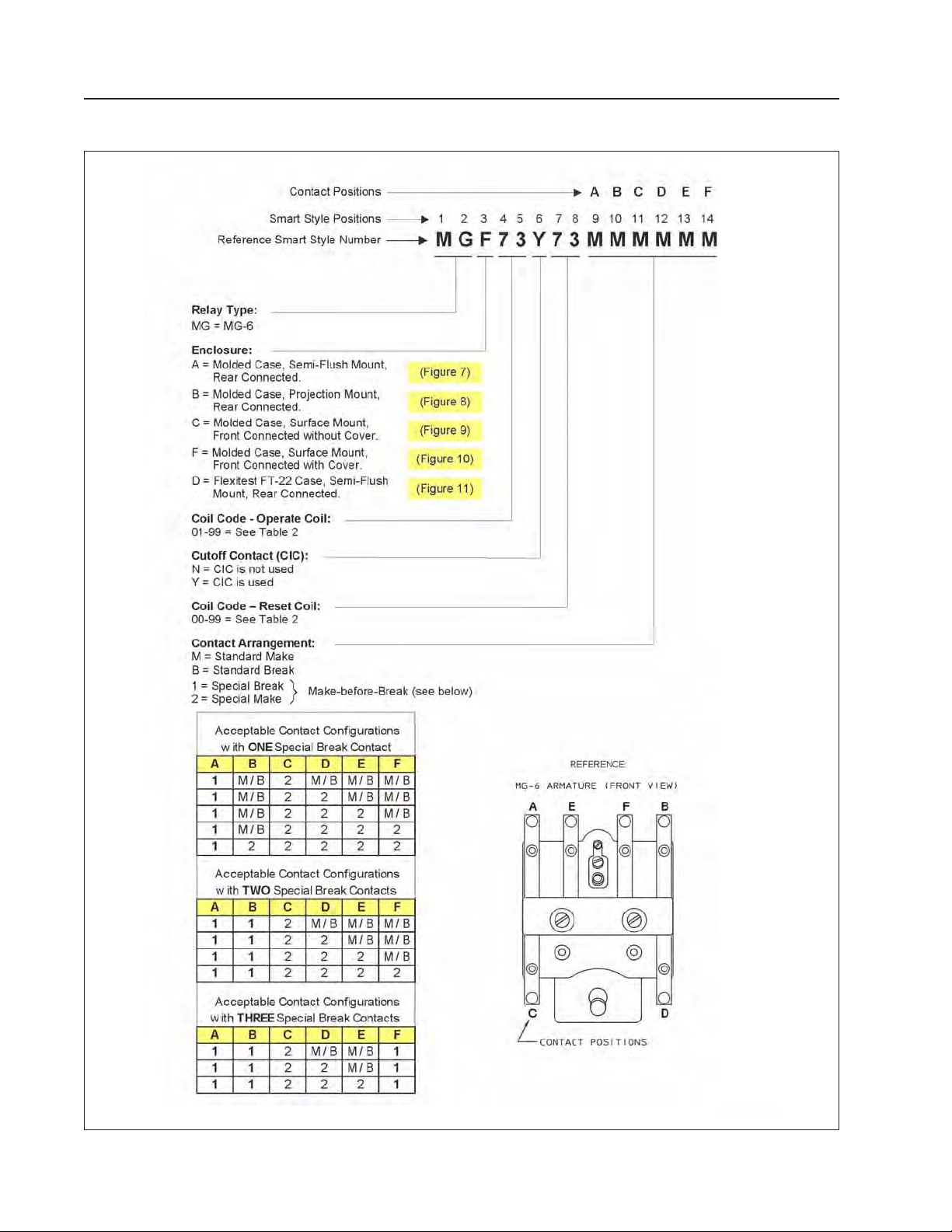
Ordering Information - MG-6 Relay
10
ABB
Page 11
MG-6 Multi-Contact Auxiliary Relay
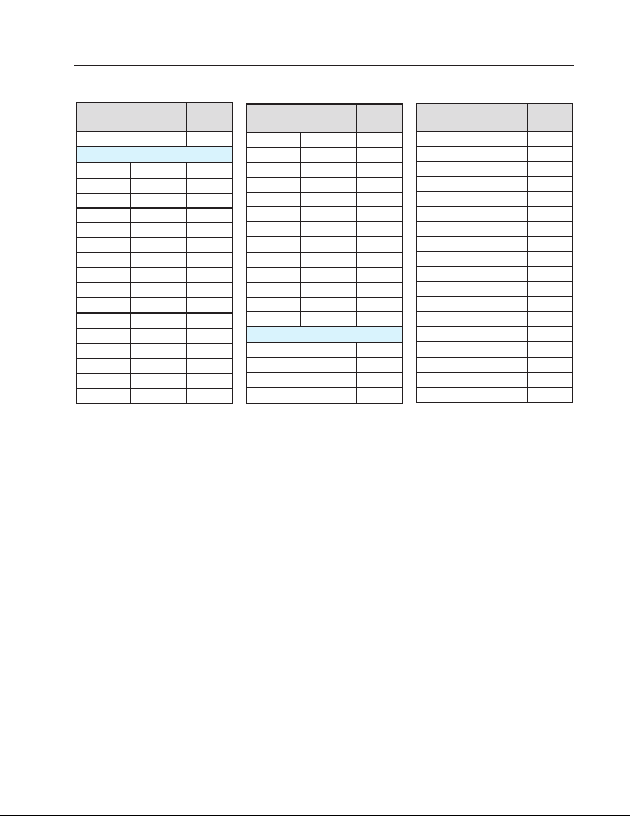
table 2 - Operate & Reset Coil Codes
IL 41-753.1 N
Rating
NONE 00
AC Coils
12 Volts 25 Hz 18
12 Volts 50 Hz 02
12 Volts 60 Hz 01
24 Volts 25 Hz 19
24 Volts 50 Hz 04
24 Volts 60 Hz 03
48 Volts 25 Hz 07
48 Volts 50 Hz 06
48 Volts 60 Hz 05
60 Volts 50 Hz 29
60 Volts 60 Hz 23
92 Volts 60 Hz 27
115 Volts 25 Hz 20
115 Volts 50 Hz 09
115 Volts 60 Hz 08
120 Volts 60 Hz 24
= Not available for Reset Coil.
*
= Not available for Operate Coil.
**
Coil
Code
**
*
Rating
208 Volts 50 Hz 26
208 Volts 60 Hz 10
220 Volts 50 Hz 25
230 Volts 25 Hz 21
230 Volts 50 Hz 12
230 Volts 60 Hz 11
460 Volts 25 Hz 16
460 Volts 50 Hz 22
460 Volts 60 Hz 13
575 Volts 25 Hz 17
575 Volts 50 Hz 15
575 Volts 60 Hz 14
5 Amps 60 Hz 28
DC Coils
6 Volts dc 77
12 Volts dc 64
24 Volts dc 65
28 Volts dc 66
Coil
Code
**
*
*
*
*
Rating
32 Volts dc 67
36 Volts dc 68
38 Volts dc 69
40 Volts dc 78
48 Volts dc 70
62 Volts dc 71
79 Volts dc 72
125 Volts dc 73
200 Volts dc 74
220 Volts dc 75
250 Volts dc 76
500 Volts dc 80
0.1 Amp dc 79
1 Amp dc 63
2 Amps dc 62
3 Amps dc 61
4 Amps dc 60
5 Amps dc 59
Coil
Code
*
*
*
*
*
*
*
*
*
*
*
ABB
11
Page 12
IL 41-753.1 N
MG-6 Multi-Contact Auxiliary Relay
Rev. 10
4D1072
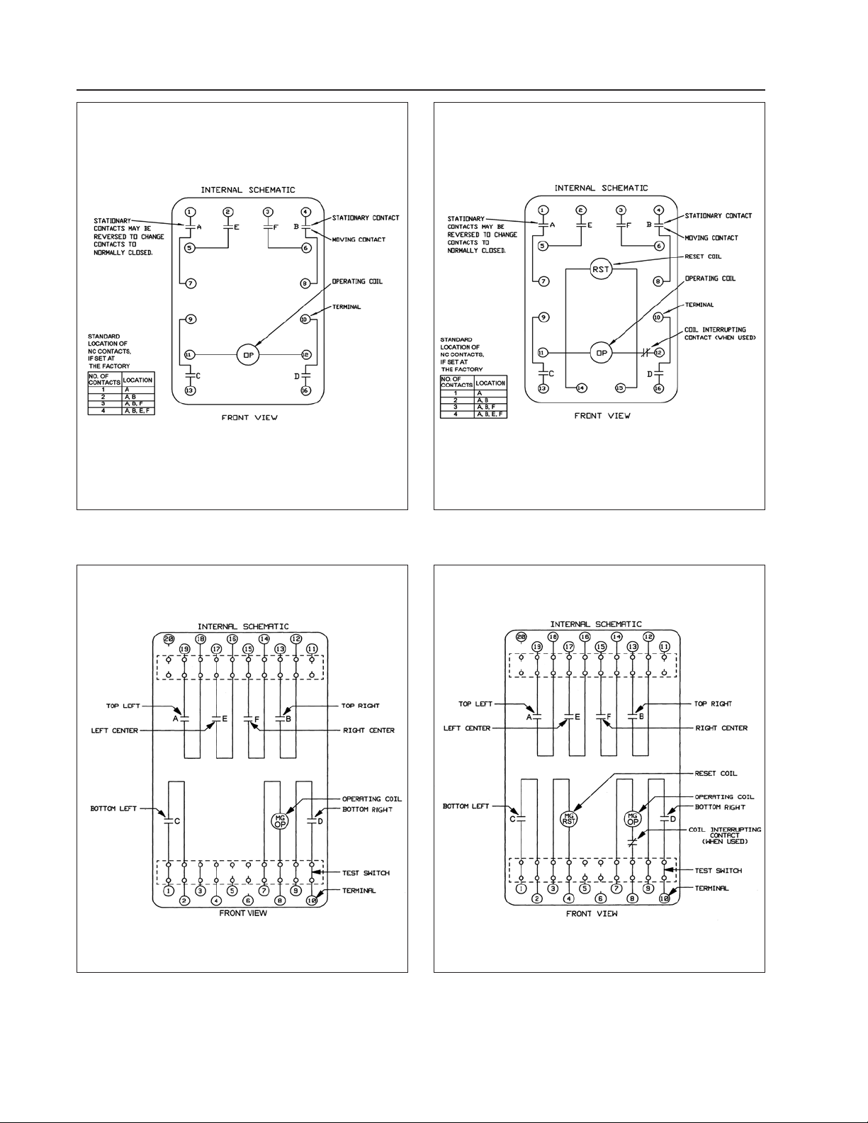
Figure 3 - Internal Schematic for the Type MG-6
Relay, Self Reset, in Molded Case
Rev. 8
4D1076
Figure 4 - Internal Schematic for the Type MG-6
Relay, Electric Reset, in Molded Case
Figure 5 - Internal Schematic for the Type MG-6
Relay, Self Reset, in FT-22 Case
12
Rev. 2
183A223
Rev. 3
183A222
Figure 6 - Internal Schematic for the Type MG-6
Relay, Electric Reset, in FT-22 Case
ABB
Page 13
MG-6 Multi-Contact Auxiliary Relay
IL 41-753.1 N
Rev. 9
183A817
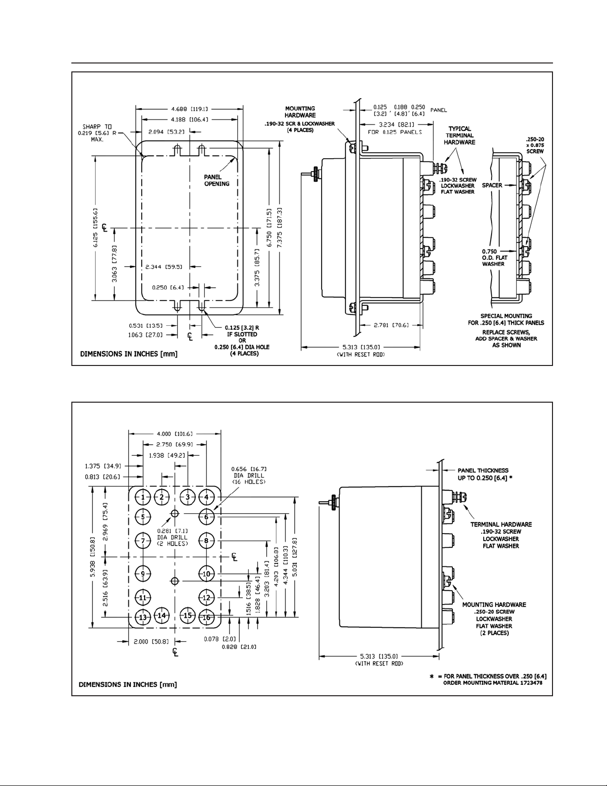
Figure 7 - Outline and Drilling Plan for MG-6 Class 1E Relay in Molded Semi-Flush Mount Case
184A370
Rev. 7
ABB
Figure 8 - Outline and Drilling Plan for MG-6 Class 1E Relay in Molded Projection Mount Case
13
Page 14
IL 41-753.1 N
MG-6 Multi-Contact Auxiliary Relay
Rev. 10
4D1122
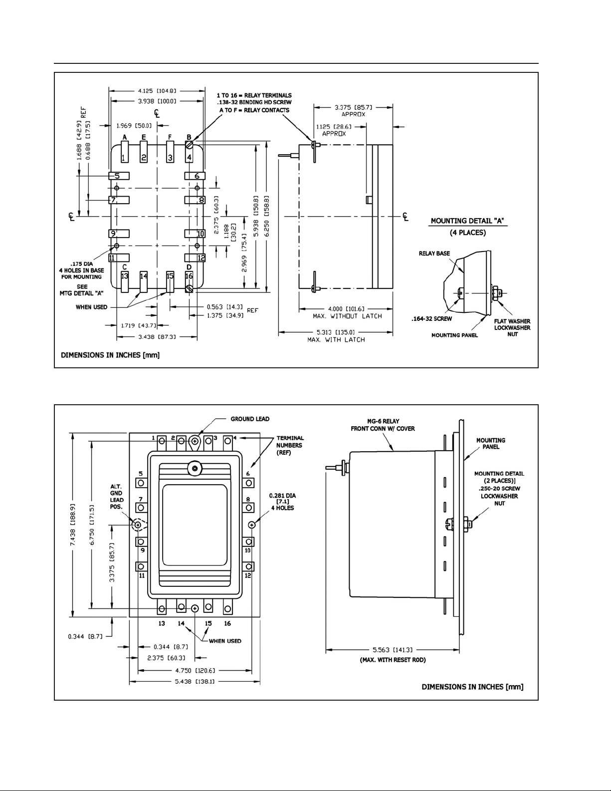
Figure 9 - Outline and Drilling Plan for MG-6 Class 1E Relay in Molded Case, Surface Mount, Front
Connected without Cover
Rev. 2
9656A20
14
Sub 4
3519A68
Figure 10 - Outline and Drilling Plan for MG-6 Class 1E Relay in Molded Case, Surface Mount, Front
Connected with Cover
ABB
Page 15
MG-6 Multi-Contact Auxiliary Relay
IL 41-753.1 N
ABB
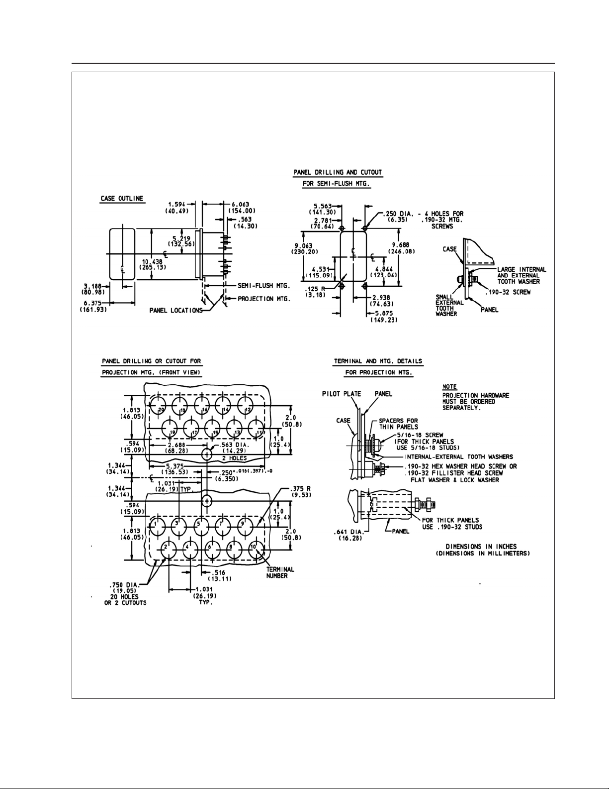
Figure 11 - Outline and Drilling Plan for MG-6 Class 1E Relay in Flexitest FT-22 Case
Rev. 14
183A158
15
Page 16

ABB
ABB Inc.
4300 Coral Ridge Drive
Coral Springs, Florida 33065
Telephone: +1 954-752-6700
Fax: +1 954-345-5329
www.abb.com/substation automation
IL 41-753.1 - Revision N
 Loading...