

Page 1
Installation, operation, maintenance and safety manual .......................................................................................... EN 3
Montage-, Betriebs-, Wartungs- und Sicherheitsanleitung .................................................................................... DE 21
Manuel d’installation, d’exploitation, de maintenance et de sécurité ..................................................................... FR 39
Manual de instalación, funcionamiento, mantenimiento y seguridad ..................................................................... ES 59
Manuale d’installazione, funzionamento e manutenzione ........................................................................................ IT 79
Manual de instalação, operação, manutenção e segurança ...................................................................................PT 99
Installations-, driffts-, underhålls- och säkerhetsmanual ..................................................................................... SV 119
Asennus-, käyttö-, kunnossapito- ja turvallisuusohje ............................................................................................ FI 137
More languages – see web site www.abb.com/motors&generators > Motors > Document library
Low voltage motors
Manual
Page 2

Layout of EC Declaration of Conformity
The Manufacturer: (Name and address of the manufacturer)
hereby declares that
The Products: (Product identication)
are in conformity with the corresponding essential requirements of following EC directive:
Directive 2006/95/EC (of 12 December 2006).
The motors are in conformity with provisions of the harmonized standard EN 60 034-1(2010) which thus
comply with Principal Elements of the Safety Objectives for Electrical Equipment stated in Annex I of
said directive.
Note: When installing motors for converter supply applications, additional requirements must be
respected regarding the motor as well as the installation, as described in installation manual delivered
with converters.
Directive 2009/125/EC (of 21st October 2009).
The motors are in conformity with requirements set in the Regulation (EC) N° 640/2009
dated of 22 July 2009.
Efciency class is dened according to the standard EN 60034-30 : March 2009.
Year of CE marking :
Signed by
____________________________
Title ____________________________
Date ____________________________
2 ABB Motors and Generators | Low voltage motor manual 01-2009
Page 3

1. Introduction ............................................................................................................................................. 5
1.1 Declaration of Conformity .................................................................................................................. 5
1.2 Validity .............................................................................................................................................. 5
2. Handling ................................................................................................................................................... 6
2.1 Reception check ............................................................................................................................... 6
2.2 Transportation and storage ............................................................................................................... 6
2.3 Lifting ................................................................................................................................................ 6
2.4 Machine weight ................................................................................................................................. 6
3. Installation and commissioning ............................................................................................................. 7
3.1 General ............................................................................................................................................. 7
3.2 Insulation resistance check ............................................................................................................... 7
3.3 Foundation ........................................................................................................................................ 7
3.4 Balancing and fitting coupling halves and pulleys .............................................................................. 8
3.5 Mounting and alignment of the motor ................................................................................................ 8
3.6 Slide rails and belt drives ................................................................................................................... 8
3.7 Machines with drain plugs for condensation ...................................................................................... 8
3.8 Cabling and electrical connections .................................................................................................... 8
3.8.1 Connections for different starting methods ............................................................................. 9
3.8.2 Connections of auxiliaries ....................................................................................................... 9
3.9 Terminals and direction of rotation ..................................................................................................... 9
4. Operation ............................................................................................................................................... 10
4.1 Use ................................................................................................................................................. 10
4.2 Cooling ........................................................................................................................................... 10
4.3 Safety considerations ...................................................................................................................... 10
Low Voltage Motors
Installation, operation, maintenance and safety manual
List of Contents Page
Low voltage motor manual 01-2009 | ABB Motors and Generators EN-3
Page 4

5. Low voltage motors in variable speed operation .............................................................................. 11
5.1 Introduction ..................................................................................................................................... 11
5.2 Winding insulation ........................................................................................................................... 11
5.2.1 Phase to phase voltages ...................................................................................................... 11
5.2.1 Phase to ground voltages .................................................................................................... 11
5.2.3 Selection of winding insulation for ACS550- and ACS800-converters ................................... 11
5.2.4 Selection of winding insulation with all other converters ........................................................ 11
5.3 Thermal protection of windings ....................................................................................................... 11
5.4 Bearing currents .............................................................................................................................. 12
5.4.1 Elimination of bearing currents with ABB ACS550 and ACS800 converters .......................... 12
5.4.2 Elimination of bearing currents with all other converters ........................................................ 12
5.5 Cabling, grounding and EMC .......................................................................................................... 12
5.6 Operating speed ............................................................................................................................. 12
5.7 Dimensioning the motor for variable speed application .................................................................... 12
5.7.1 General ................................................................................................................................ 12
5.7.2 Dimensioning with ABB ACS800 converters with DTC control .............................................. 12
5.7.3 Dimensioning with ABB ACS550 converters ......................................................................... 13
5.7.4 Dimensioning with other voltage source PWM-type converters ............................................. 13
5.7.5 Short time overloads ............................................................................................................ 13
5.8 Rating plates ................................................................................................................................... 13
5.9 Commissioning the variable speed application ................................................................................ 13
6. Maintenance .......................................................................................................................................... 14
6.1 General inspection .......................................................................................................................... 14
6.1.1 Standby motors ......................................................................................................................14
6.2 Lubrication ............................................................................................................................................... 14
6.2.1 Machines with permanently greased bearings ...................................................................... 14
6.2.2 Motors with regreasable bearings ......................................................................................... 15
6.2.3 Lubrication intervals and amounts ........................................................................................ 15
6.2.4 Lubricants ............................................................................................................................ 17
7. After Sales Support ............................................................................................................................... 18
7.1 Spare parts ..................................................................................................................................... 18
7.2 Rewinding ....................................................................................................................................... 18
7.3 Bearings ......................................................................................................................................... 18
8. Environmental requirements ................................................................................................................ 18
8.1 Noise levels ..................................................................................................................................... 18
9. Troubleshooting .................................................................................................................................... 19
EN-4 ABB Motors and Generators | Low voltage motor manual 01-2009
Page 5

1. Introduction
NOTE!
These instructions must be followed to ensure safe
and proper installation, operation and maintenance
of the machine. They should be brought to the
attention of anyone who installs, operates or
maintains the machine or associated equipment.
The machine is intended for installation and use by
qualified personnel, familiar with health and safety
requirements and national legislation. Ignoring these
instructions may invalidate all applicable warranties.
1.1 Declaration of Conformity
Declarations of Conformity with respect to the Low voltage
Directive 73/23/EEC amended by Directive 93/68 EEC are
issued separately with individual machines.
The Declaration of Conformity also satisfies the
requirements of a Declaration of Incorporation with
respect to the Machinery Directive 98/37/EEC,
Art 4.2 Annex II, sub B
1.2 Validity
The instructions are valid for the following ABB electrical
machine types, in both motor and generator operation.
series MT*, MXMA,
series M2A*/M3A*, M2B*/M3B*, M4B*, M2C*/M3C*,
M2F*/M3F*, M2L*/M3L*, M2M*/M3M*, M2Q*,
M2R*/M3R*, M2V*/M3V*
in frame sizes 56 - 450.
There is a separate manual for e.g. Ex motors ‘Low voltage
motors for hazardous areas: Installation, operation and
maintenance Manual’ (Low Voltage Motors/Manual for Exmotors).
Additional information is required for some machine types
due to special application and/or design considerations.
Additional information is available for the following motors:
– roller table motors
– water cooled motors
– open drip proof motors
– smoke venting motors
– brake motors
– motors for high ambient temperatures
Low voltage motor manual 01-2009 | ABB Motors and Generators EN-5
Page 6
2. Handling
2.1 Reception check
Immediately upon receipt check the motor for external
damage (e.g. shaft-ends and flanges and painted surfaces)
and if found, inform the forwarding agent without delay.
Check all rating plate data, especially voltage and winding
connection (star or delta). The type of bearing is specified
on the rating plate of all motors except the smallest frame
sizes.
2.2 Transportation and storage
The motor should always be stored indoors (above
–20°C), in dry, vibration free and dust free conditions.
During transportation, shocks, falls and humidity should be
avoided. In other conditions, please contact ABB.
Unprotected machined surfaces (shaft-ends and flanges)
should be treated against corrosion.
It is recommended that shafts are rotated periodically by
hand to prevent grease migration.
Anti-condensation heaters, if fitted, are recommended to
be used to avoid water condensing in the motor.
The motor must not be subject to any external vibrations at
standstill so as to avoid causing damage to the bearings.
Motors fitted with cylindrical-roller and/or angular contact
bearings must be fitted with locking devices during
transport.
2.3 Lifting
All ABB motors above 25 kg are equipped with lifting lugs
or eyebolts.
Only the main lifting lugs or eyebolts of the motor should be
used for lifting the motor. They must not be used to lift the
motor when it is attached to other equipment.
Lifting lugs for auxiliaries (e.g. brakes, separate cooling
fans) or terminal boxes must not be used for lifting the
motor.
Motors with the same frame may have a different center of
gravity because of different output, mounting arrangements
and auxiliary equipment.
Damaged lifting lugs must not be used. Check that
eyebolts or integrated lifting lugs are undamaged before
lifting.
Lifting eyebolts must be tightened before lifting. If needed,
the position of the eyebolt can be adjusted using suitable
washers as spacers.
Ensure that proper lifting equipment is used and that the
sizes of the hooks are suitable for the lifting lugs.
Care must be taken not to damage auxiliary equipment and
cables connected to the motor.
2.4 Machine weight
The total machine weight can vary within the same
frame size (center height) depending on different output,
mounting arrangement and auxiliaries.
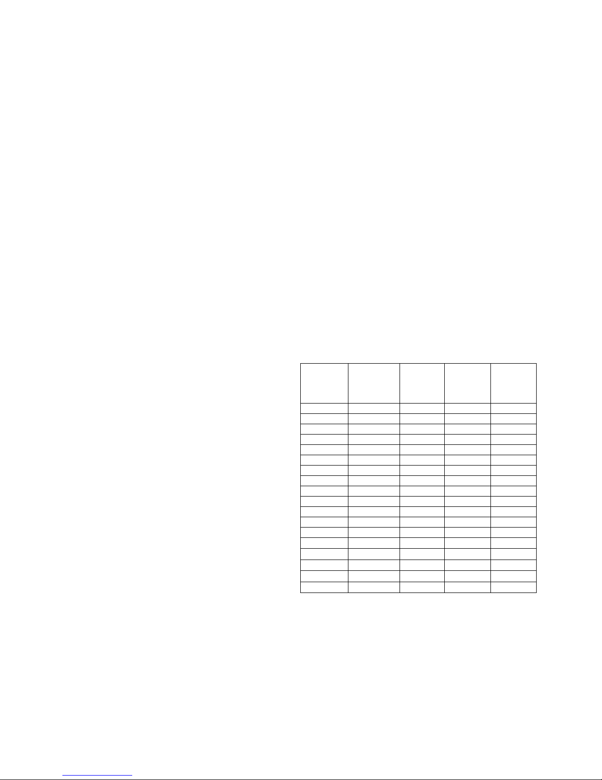
The following table shows estimated maximum weights
for machines in their basic versions as a function of frame
material.
The actual weight of all ABB’s motors, except the smallest
frame sizes (56 and 63) is shown on the rating plate.
Frame
size
Aluminum
Weight
kg
Cast iron
Weight
kg
Steel
Weight
kg
Add.
for brake
56 4.5 - 63 6 - 71 8 13 5
80 12 20 8
90 17 30 10
100 25 40 16
112 36 50 20
132 63 90 30
160 95 130 30
180 135 190 45
200 200 275 55
225 265 360 75
250 305 405 75
280 390 800 600 315 - 1700 1000 355 - 2700 2200 400 - 3500 3000 450 - 4500 - -
EN-6 ABB Motors and Generators | Low voltage motor manual 01-2009
Page 7
3. Installation and commissioning
WARNING
Disconnect and lock out before working on the
motor or the driven equipment.
3.1 General
All rating plate values must be carefully checked to ensure
that the motor protection and connection will be properly
done.
WARNING
In case of motors mounted with the shaft upwards
and water or liquids are expected to go down along
the shaft, the user must take in account to mount
some means capable of preventing it.
Remove transport locking if employed. Turn shaft by hand
to check free rotation if possible.
Motors equipped with roller bearings:
Running the motor with no radial force applied to the shaft
may damage the roller bearing.
Motors equipped with angular contact bearing:
Running the motor with no axial force applied in the right
direction in relation to the shaft may damage the angular
contact bearing.
WARNING
For machines with angular contact bearings the axial
force must not by any means change direction.
The type of bearing is specified on the rating plate.
Motors equipped with regreasing nipples:
When starting the motor for the first time, or after long
storage, apply the specified quantity of grease.
For details, see section “6.2.2 Motors with regreasable
bearings”.
3.2 Insulation resistance check
Measure insulation resistance before commissioning and
when winding dampness is suspected.
WARNING
Disconnect and lock out before working on the
motor or the driven equipment.
Insulation resistance, corrected to 25°C, must exceed the
reference value, i.e. 100 MΩ (measured with 500 or 1000 V
DC). The insulation resistance value is halved for each 20°C
rise in ambient temperature.
WARNING
The motor frame must be grounded and the
windings should be discharged against the frame
immediately after each measurement to avoid risk of
electrical shock.
If the reference resistance value is not attained, the
winding is too damp and must be oven dried. The oven
temperature should be 90°C for 12-16 hours followed by
105°C for 6-8 hours.
Drain hole plugs, if fitted, must be removed and closing
valves, if fitted, must be opened during heating. After
heating, make sure the plugs are refitted. Even if the drain
plugs are fitted, it is recommended to disassemble the end
shields and terminal box covers for the drying process.
Windings drenched in seawater normally need to be
rewound.
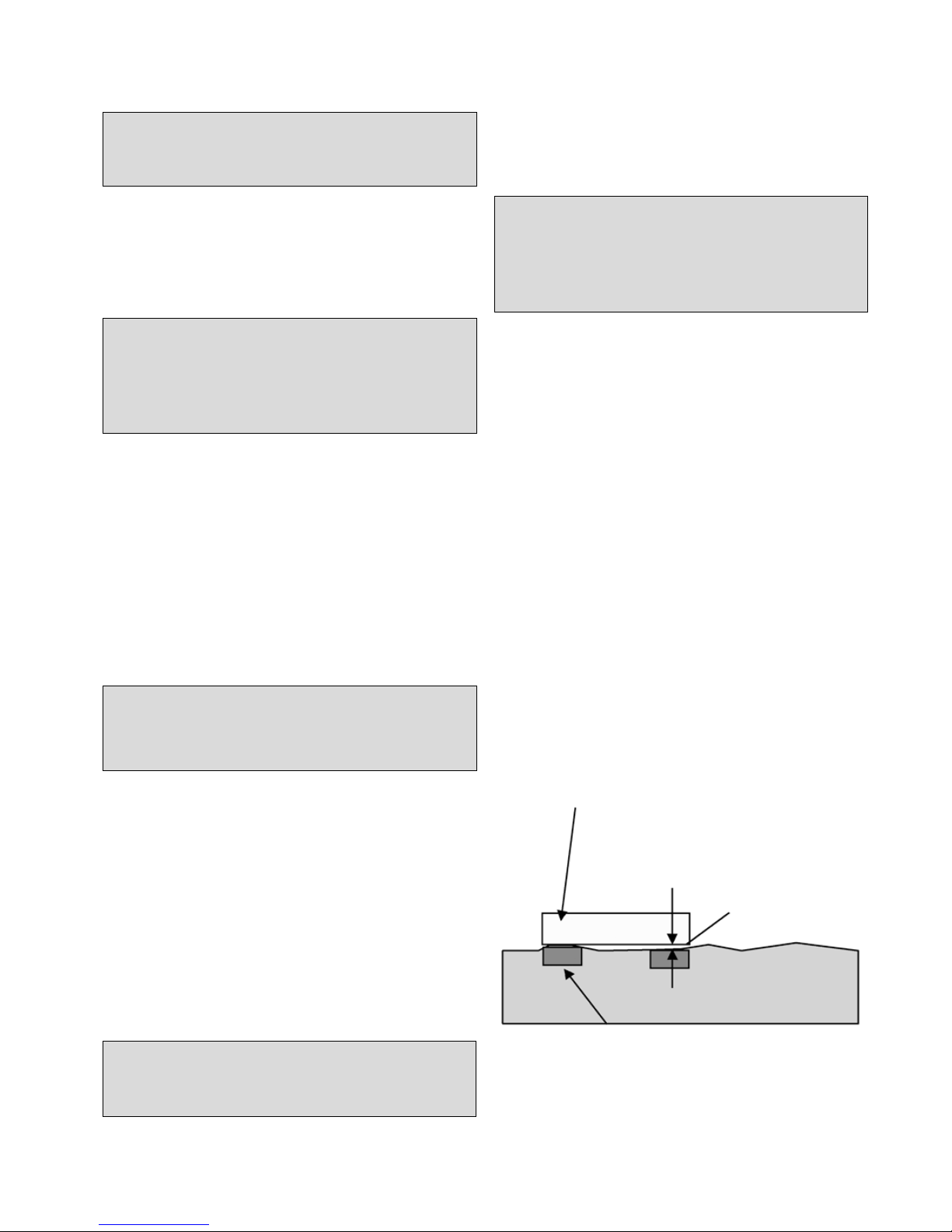
3.3 Foundation
The end user has full responsibility for preparation of the
foundation.
Metal foundations should be painted to avoid corrosion.
Foundations must be even, see figure below, and
sufficiently rigid to withstand possible short circuit forces.
They must be designed and dimensioned to avoid the
transfer of vibration to the motor and vibration caused by
resonance.
Note! Height difference shall
not exceed ± 0,1mm referred
to any other motor foot
Ruler
Foot location
Low voltage motor manual 01-2009 | ABB Motors and Generators EN-7
Page 8

3.4 Balancing and fitting coupling
halves and pulleys
As standard, balancing of the motor has been carried out
using half key
When balancing with full key, the shaft is marked with
YELLOW tape, with the text “Balanced with full key”.
In case of balancing without key, the shaft is marked with
BLUE tape, with the text “Balanced without key”.
Coupling halves or pulleys must be balanced after
machining the keyways. Balancing must be done in
accordance with the balancing method specified for the
motor.
Coupling halves and pulleys must be fitted on the shaft by
using suitable equipment and tools which do not damage
the bearings and seals.
Never fit a coupling half or pulley by hammering or by
removing it using a lever pressed against the body of the
motor.
3.5 Mounting and alignment
of the motor
Ensure that there is enough space for free airflow around
the motor. Minimum requirements for free space behind the
motor fan cover can be found from the product catalog or
from the dimension drawings available from the web: see
www.abb.com/motors&generators.
Correct alignment is essential to avoid bearing, vibration
and possible shaft failures.
Mount the motor on the foundation using the appropriate
bolts or studs and place shim plates between the
foundation and the feet.
Align the motor using appropriate methods.
If applicable, drill locating holes and fix the locating pins into
position.
Mounting accuracy of coupling half: check that clearance
b is less than 0.05 mm and that the difference a1 to a2 is
also less than 0.05 mm. See Figure 3.
Re-check the alignment after final tightening of the bolts or
studs.
Do not exceed permissible loading values for bearings as
stated in the product catalogues.
3.6 Slide rails and belt drives
Fasten the motor to the slide rails as shown in Figure 2.
Place the slide rails horizontally on the same level.
Check that the motor shaft is parallel with the drive shaft.
Belts must be tensioned according to the instructions of
the supplier of the driven equipment. However, do not
exceed the maximum belt forces (i.e. radial bearing loading)
stated in the relevant product catalogues.
WARNING
Excessive belt tension will damage bearings and can
cause shaft damage.
3.7 Machines with drain plugs
for condensation
Check that drain holes and plugs face downwards.
Machines with sealable plastic drain plugs are delivered in
open position. In very dusty environments, all drain holes
should be closed.
3.8 Cabling and electrical
connections
The terminal box on standard single speed motors normally
contains six winding terminals and at least one earth
terminal.
In addition to the main winding and earthing terminals, the
terminal box can also contain connections for thermistors,
heating elements or other auxiliary devices.
Suitable cable lugs must be used for the connection of all
main cables. Cables for auxiliaries can be connected into
their terminal blocks as such.
Machines are intended for fixed installation only. If not
otherwise specified, cable entry threads are metric. The IPclass of the cable gland must be at least the same as those
of the terminal boxes.
Unused cable entries must be closed with blanking
elements according to the IP class of the terminal box.
The degree of protection and diameter are specified in the
documents relating to the cable gland.
EN-8 ABB Motors and Generators | Low voltage motor manual 01-2009
Page 9

WARNING
Use appropriate cable glands and seals in the cable
entries according to the type and diameter of the
cable.
Additional information on cables and glands suitable for
variable speed applications can be found from chapter 5.5.
Earthing must be carried out according to local regulations
before the machine is connected to the supply voltage.
Ensure that the motor protection corresponds to the
environment and weather conditions; for example, make
sure that water cannot enter the motor or the terminal
boxes.
The seals of terminal boxes must be placed correctly in the
slots provided, to ensure the correct IP class.
3.8.1 Connections for different
starting methods
The terminal box on standard single speed motors normally
contains six winding terminals and at least one earth
terminal. This enables the use of DOL- or Y/D –starting.
See Figure 1.
For two-speed and special motors, the supply connection
must follow the instructions inside the terminal box or in the
motor manual.
The voltage and connection are stamped on the rating
plate.
Direct-on-line starting (DOL):
Y or D winding connections may be used.
For example, 690 VY, 400 VD indicates Y-connection for
690 V and D-connection for 400 V.
Star/Delta starting (Y/D):
The supply voltage must be equal to the rated voltage of
the motor when using a D-connection.
Remove all connection links from the terminal block.
Other starting methods and severe starting
conditions:
In case other starting methods are used, such as a soft
starter, or if starting conditions are particularly difficult,
please consult ABB first.
3.8.2 Connections of auxiliaries
If a motor is equipped with thermistors or other RTDs
(Pt100, thermal relays, etc.) and auxiliary devices, it is
recommended they be used and connected by appropriate
means. Connection diagrams for auxiliary elements and
connection parts can be found inside the terminal box.
Maximum measuring voltage for the thermistors is 2.5 V.
Maximum measuring current for Pt100 is 5 mA. Using a
higher measuring voltage or current may cause errors in
readings or damage the system.
The insulations of the winding thermal sensors is of basic
type. While connecting the sensors to control systems etc,
ensure adequate insulation or isolation, see IEC 60664.
NOTE!
Ensure the insulation level or isolation of thermistor
circuit, see IEC 60664.
3.9 Terminals and direction
of rotation
The shaft rotates clockwise when viewing the shaft face at
the motor drive end, and the line phase sequence - L1, L2,
L3 - is connected to the terminals as shown in Figure 1.
To alter the direction of rotation, interchange any two
connections on the supply cables.
If the motor has a unidirectional fan, ensure that it rotates in
the same direction as the arrow marked on the motor.
Low voltage motor manual 01-2009 | ABB Motors and Generators EN-9
Page 10

4. Operation
4.2 Cooling
Check that the motor has sufficient airflow. Ensure that no
nearby objects or direct sunshine radiate additional heat to
the motor.
For flange mounted motors (e.g. B5, B35, V1), make sure
that the construction allows sufficient air flow on the outer
surface of the flange.
4.3 Safety considerations
The machine is intended for installation and use by qualified
personnel, familiar with health and safety requirements and
national legislation.
Safety equipment necessary for the prevention of accidents
at the installation and operating site must be provided in
accordance with local regulations.
WARNING
Do not carry out work on motor, connection cables
or accessories such as frequency converters,
starters, brakes, thermistor cables or heating
elements when voltage is applied.
Points to observe
1. Do not step on the motor.
2. The temperature of the outer casing of the motor
may be too hot to touch during normal operation and
especially after shut-down.
3. Some special motor applications require special
instructions (e.g. using frequency converter supplies).
4. Be aware of rotating parts of the motor.
5. Do not open terminal boxes while energized.
4.1 Use
The motors are designed for the following conditions unless
otherwise stated on the rating plate.
- Normal ambient temperature limits are -20°C to +40°C.
- Maximum altitude 1000 m above sea level.
- Tolerance for supply voltage is ±5% and for frequency
±2% according to EN / IEC 60034-1 (2004).
The motor can only be used in applications it is intended
for. The rated nominal values and operational conditions
are shown on the motor rating plates. In addition, all
requirements of this manual and other related instructions
and standards must be followed.
If these limits are exceeded, motor data and construction
data must be checked. Please contact ABB for further
information.
WARNING
Ignoring any of given instructions or maintenance of
the apparatus may jeopardize the safety and thus
prevents the use of the machine.
EN-10 ABB Motors and Generators | Low voltage motor manual 01-2009
Page 11

5. Low voltage motors in variable speed operation
5.1 Introduction
This part of the manual provides additional instructions for
motors used in frequency converter supply. Instructions
provided in this and respective manuals of selected
frequency converter must be followed to ensure safety and
availability of the motor.
Additional information may be required by ABB to decide
on the suitability for some machine types used in special
applications or with special design modifications.
5.2 Winding insulation
Variable speed drives cause higher voltage stresses than
the sinusoidal supply on the winding of the motor and
therefore the winding insulation of the motor as well as
the filter at the converter output must be dimensioned
according following instructions.
5.2.1 Phase to phase voltages
The maximum allowed phase to phase voltage peaks at
the motor terminal as a function of the rise time of the pulse
can be seen in Figure 1.
The highest curve “ABB Special Insulation” applies to
motors with a special winding insulation for frequency
converter supply, variant code 405.
The “ABB Standard Insulation” applies to all other motors
covered by this manual.
5.2.2 Phase to ground voltages
The allowed phase to ground voltage peaks at motor
terminals are:
Standard Insulation 1300 V peak
Special Insulation 1800 V peak
5.2.3 Selection of winding insulation for
ACS800 and ACS550 converters
In the case of ABB ACS800-series and ACS550-series
single drives with a diode supply unit (uncontrolled DC
voltage), the selection of winding insulation and filters can
be made according to table below:
Nominal supply
voltage UN of the
converter
Winding insulation and
filters required
U
N
≤ 500 V ABB Standard insulation
U
N
≤ 600 V ABB Standard insulation
+ dU/dt lters
OR
ABB Special insulation
(variant code 405)
U
N
≤ 690 V ABB Special insulation
(variant code 405)
AND
dU/dt-lters at converter
output
U
N
≤ 690 V
AND
cable length > 150 m
ABB Special insulation
(variant code 405)
For more information on resistor braking and converters
with controlled supply units, please contact ABB.
5.2.4 Selection of winding insulation
with all other converters
The voltage stresses must be limited below accepted limits.
Please contact the system supplier to ensure the safety of
the application. The influence of possible filters must be
taken into account while dimensioning the motor.
5.3 Thermal protection
Most of the motors covered by this manual are equipped
with PTC thermistors in the stator windings. It is
recommended to connect those to the frequency converter
by appropriate means. See also chapter 3.8.2.
Low voltage motor manual 01-2009 | ABB Motors and Generators EN-11
Page 12

5.4 Bearing currents
Insulated bearings or bearing constructions, common
mode filters and suitable cabling and grounding methods
must be used according to the following instructions:
5.4.1 Elimination of bearing currents with
ABB ACS800 and ACS550 converters
In the case of the ABB ACS800 and ACS550-series
frequency converter with a diode supply unit, the following
methods must be used to avoid harmful bearing currents in
the motors:
Nominal Power (Pn)
and / or Frame size (IEC)
Preventive measures
Pn < 100 kW No actions needed
Pn ≥ 100 kW
OR
IEC 315 ≤ Frame size
≤ IEC 355
Insulated non-drive end
bearing
Pn ≥ 350 kW
OR
IEC 400 ≤ Frame size
≤ IEC 450
Insulated non-drive end
bearing
AND
Common mode filter at
the converter
Insulated bearings which have aluminum oxide coated
inner and/or outer bores or ceramic rolling elements,
are recommended. Aluminum oxide coatings shall also
be treated with a sealant to prevent dirt and humidity
penetrating into the porous coating. For the exact type of
bearing insulation, see the motor’s rating plate. Changing
the bearing type or insulation method without ABB’s
permission is prohibited.
5.4.2 Elimination of bearing currents
with all other converters
The user is responsible for protecting the motor and driven
equipment from harmful bearing currents. Instructions
described in Chapter 5.4.1 can be used as guideline, but
their effectiveness cannot be guaranteed in all cases.
5.5 Cabling, grounding and EMC
To provide proper grounding and to ensure compliance
with any applicable EMC requirements, motors above 30
kW shall be cabled by shielded symmetrical cables and
EMC glands, i.e. cable glands providing 360° bonding.
Also for smaller motors symmetrical and shielded cables
are highly recommended. Make the 360° grounding
arrangement at all the cable entries as described in the
instructions for the glands. Twist the cable shields into
bundles and connect to the nearest ground terminal/bus
bar inside the terminal box, converter cabinet, etc.
NOTE!
Proper cable glands providing 360° bonding must
be used at all termination points, e.g. at motor,
converter, possible safety switch, etc.
For motors of frame size IEC 280 and upward, additional
potential equalization between the motor frame and the
driven equipment is needed, unless both are mounted on
a common steel base. In this case, the high frequency
conductivity of the connection provided by the steel
base should be checked by, for example, measuring the
potential difference between the components.
More information about grounding and cabling of variable
speed drives can be found in the manual “Grounding and
cabling of the drive system” (Code: 3AFY 61201998).
5.6 Operating speed
For speeds higher than the nominal speed stated on the
motor’s rating plate or in the respective product catalogue,
ensure that either the highest permissible rotational speed
of the motor or the critical speed of the whole application is
not exceeded.
5.7 Dimensioning the motor
for variable speed application
5.7.1 General
In case of ABB’s frequency converters, the motors can
be dimensioned by using ABB’s DriveSize dimensioning
program. The tool is downloadable from the ABB website
(www.abb.com/motors&generators).
For application supplied by other converters, the motors
must be dimensioned manually. For more information,
please contact ABB.
The loadability curves (or load capacity curves) are based
on nominal supply voltage. Operation in under or over
voltage conditions may influence on the performance of the
application.
5.7.2 Dimensioning with ABB ACS800
converters with DTC control
The loadability curves presented in Figures 4a - 4d are valid
for ABB ACS800 converters with uncontrolled DC-voltage
and DTC-control. The figures show the approximate
maximum continuous output torque of the motors as a
function of supply frequency. The output torque is given
as a percentage of the nominal torque of the motor. The
values are indicative and exact values are available on
request.
NOTE!
The maximum speed of the motor must not be
exceeded!
EN-12 ABB Motors and Generators | Low voltage motor manual 01-2009
Page 13

5.7.3 Dimensioning with ABB ACS550
converters
The loadability curves presented in Figures 5a - 5d are
valid for ABB ACS550 series converters. The figures show
the approximate maximum continuous output torque of
the motors as a function of supply frequency. The output
torque is given as a percentage of the nominal torque of
the motor. The values are indicative and exact values are
available on request.
NOTE!
The maximum speed of the motor must not be
exceeded!
5.7.4 Dimensioning with other voltage
source PWM-type converters
For other converters, which have uncontrolled DC
voltage and minimum switching frequency of 3 kHz,
the dimensioning instructions of ACS550 can be used
as guidelines, but it shall be noted, that the actual
thermal loadability can also be lower. Please contact the
manufacturer of the converter or the system supplier.
NOTE!
The actual thermal loadability of a motor may be
lower than shown by guideline curves.
5.7.5 Short time overloads
ABB motors can usually be temporarily overloaded as well
as used in intermittent duties. The most convenient method
to dimension such applications is to use the DriveSize tool.
5.8 Rating plates
The usage of ABB’s motors in variable speed applications
do not usually require additional rating plates and the
parameters required for commissioning the converter can
be found from the main rating plate. However, in some
special applications the motors can be equipped with
additional rating plates for variable speed applications and
those include following information:
- speed range
- power range
- voltage and current range
- type of torque (constant or quadratic)
- converter type and required minimum switching
frequency
5.9 Commissioning the variable
speed application
The commissioning of the variable speed application must
be done according to the instructions of the frequency
converter and local laws and regulations. The requirements
and limitations set by the application must also be taken
into account.
All parameters needed for setting the converter must be
taken from the motor rating plates. The most often needed
parameters are:
- Motor nominal voltage
- Motor nominal current
- Motor nominal frequency
- Motor nominal speed
- Motor nominal power
Note: In case of missing or inaccurate information, do not
operate the motor before ensuring correct settings!
ABB recommends using all the suitable protective features
provided by the converter to improve the safety of the
application. Converters usually provide features such as
(names and availability of features depend on manufacturer
and model of the converter):
- Minimum speed
- Maximum speed
- Acceleration and deceleration times
- Maximum current
- Maximum Torque
- Stall protection
Low voltage motor manual 01-2009 | ABB Motors and Generators EN-13
Page 14

6. Maintenance
WARNING
Voltage may be connected at standstill inside the
terminal box for heating elements or direct winding
heating.
WARNING
The capacitor in single-phase motors can retain a
charge that appears across the motor terminals, even
when the motor has reached standstill.
WARNING
A motor with frequency converter supply may
energize even if the motor is at standstill.
6.1 General inspection
1. Inspect the motor at regular intervals, at least once a
year. The frequency of checks depends on, for example,
the humidity level of the ambient air and on the local
weather conditions. This can initially be determined
experimentally and must then be strictly adhered to.
2. Keep the motor clean and ensure free ventilation
airflow. If the motor is used in a dusty environment,
the ventilation system must be regularly checked and
cleaned.
3. Check the condition of shaft seals (e.g. V-ring or radial
seal) and replace if necessary.
4. Check the condition of connections and mounting and
assembly bolts.
5. Check the bearing condition by listening for any unusual
noise, vibration measurement, bearing temperature,
inspection of spent grease or SPM bearing monitoring.
Pay special attention to bearings when their calculated
rated life time is coming to an end.
When signs of wear are noticed, dismantle the motor,
check the parts and replace if necessary. When bearings
are changed, replacement bearings must be of the same
type as those originally fitted. The shaft seals have to be
replaced with seals of the same quality and characteristics
as the originals when changing bearings.
In the case of the IP 55 motor and when the motor
has been delivered with a plug closed, it is advisable to
periodically open the drain plugs in order to ensure that
the way out for condensation is not blocked and allows
condensation to escape from the motor. This operation
must be done when the motor is at a standstill and has
been made safe to work on.
6.1.1 Standby motors
If the motor is in standby for a longer period of time on
a ship or in other vibrating environment the following
measures have to be taken:
1. The shaft must be rotated regularly every 2 weeks (to
be reported) by means of start up of the system. In case
a start up is not possible, due to any reason, at least
the shaft has to be turned by hand in order to achieve
a different position once a week. Vibrations caused by
other vessel's equipment will cause bearing pitting which
should be minimized by regular operation / hand turning.
2. The bearing must be greased while rotating the shaft
every year (to be reported). If the motor has been
provided with roller bearing at the driven end the
transport lock to be removed before rotating the shaft.
The transport locking must be remounted in case of
transportation.
3. All vibrations must be avoided to prevent a bearing from
failuring. All instructions in the motor instruction manual
for commissioning and maintenance have to be followed
additionally. The warranty will not cover the winding and
bearing damages if these instructions have not been
followed.
6.2 Lubrication
WARNING
Beware of all rotating parts!
WARNING
Grease can cause skin irritation and eye
inflammation. Follow all safety precautions specified
by the manufacturer.
Bearing types are specified in the respective product
catalogs and on the rating plate of all motors except
smaller frame sizes.
Reliability is a vital issue for bearing lubrication intervals.
ABB uses mainly the L
1
-principle (i.e. that 99% of the
motors are certain to make the life time) for lubrication.
6.2.1 Machines with permanently
greased bearings
Bearings are usually permanently greased bearings of 1Z,
2Z, 2RS or equivalent types.
As a guide, adequate lubrication for sizes up to 250 can be
achieved for the following duration, according to L
10
.
EN-14 ABB Motors and Generators | Low voltage motor manual 01-2009
Page 15

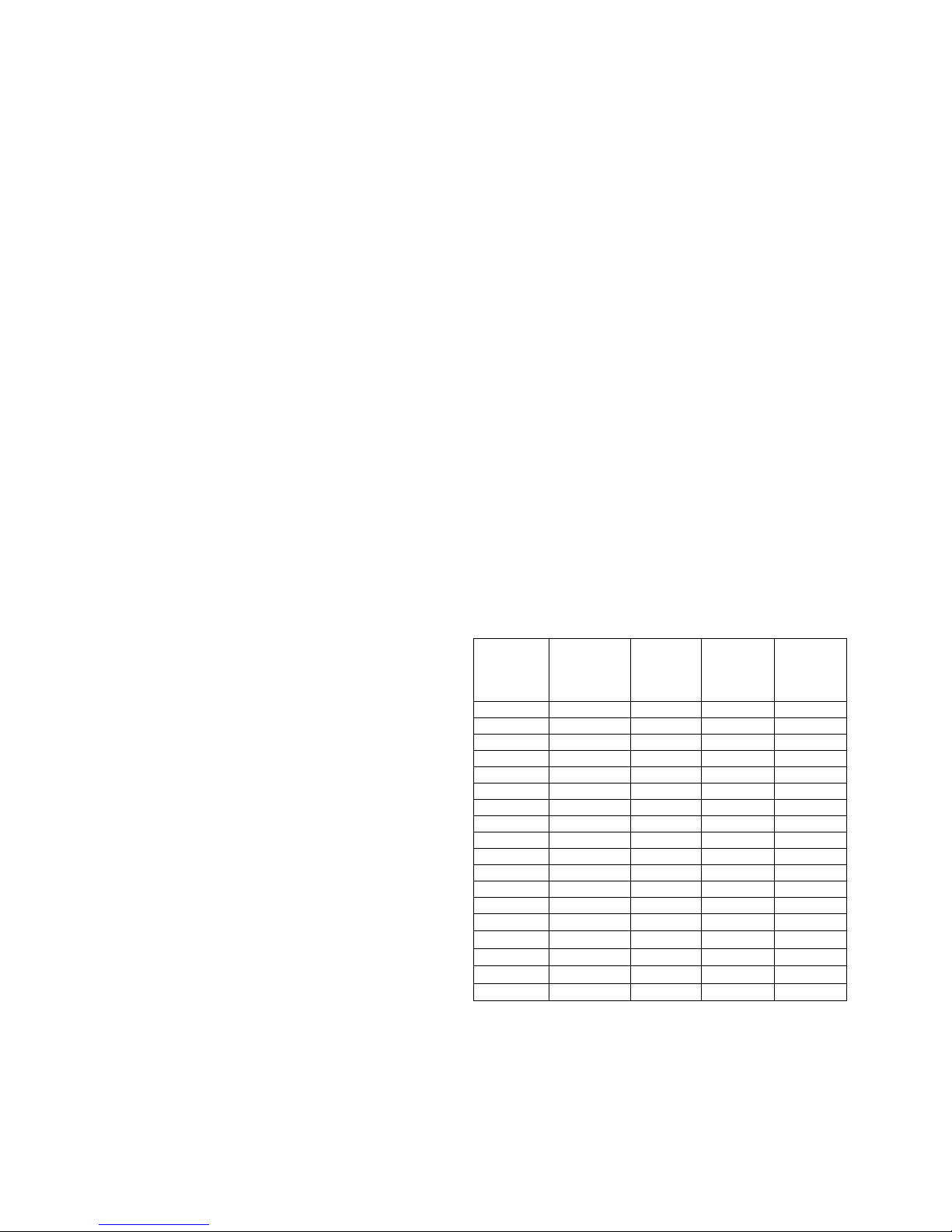
Duty hours for permanently greased bearings at ambient
temperatures of 25 and 40° C are:
Lubrication intervals according to L
10
principle
Frame size Poles
Duty hours
at 25° C
Duty hours
at 40° C
56-63 2-8 40 000 40 000
71 2 40 000 40 000
71 4-8 40 000 40 000
80-90 2 40 000 40 000
80-90 4-8 40 000 40 000
100-112 2 40 000 32 000
100-112 4-8 40 000 40 000
132 2 40 000 27 000
132 4-8 40 000 40 000
160 2 40 000 36 000
160 4-8 40 000 40 000
180 2 38 000 38 000
180 4-8 40 000 40 000
200 2 27 000 27 000
200 4-8 40 000 40 000
225 2 23 000 18 000
225 4-8 40 000 40 000
250 2 16 000 13 000
250 4-8 40 000 39 000
Data valid at 50 Hz, for 60 Hz reduce values for 20 %.
These values are valid for permitted load values given in
the product catalog. Depending on application and load
conditions, see the applicable product catalog or contact
ABB.
Operation hours for vertical motors are half of the above
values.
6.2.2 Motors with regreasable bearings
Lubrication information plate and general lubrication
advice
If the machine is equipped with a lubrication information
plate, follow the given values.
On the lubrication information plate, greasing intervals
regarding mounting, ambient temperature and rotational
speed are defined.
During the first start or after a bearing lubrication a
temporary temperature rise may appear, approximately 10
to 20 hours.
Some motors may be equipped with a collector for old
grease. Follow the special instructions given for the
equipment.
A. Manual lubrication
Regreasing while the motor is running
– Remove grease outlet plug or open closing valve if fitted.
– Be sure that the lubrication channel is open
– Inject the specified amount of grease into the bearing.
– Let the motor run for 1-2 hours to ensure that all excess
grease is forced out of the bearing. Close the grease
outlet plug or closing valve if fitted.
Regreasing while the motor is at a standstill
If it is not possible to regrease the bearings while the
motors are running, lubrication can be carried out while the
machine is at a standstill.
– In this case use only half the quantity of grease and then
run the motor for a few minutes at full speed.
– When the motor has stopped, apply the rest of the
specified amount of grease to the bearing.
– After 1-2 running hours close the grease outlet plug or
closing valve if fitted.
B. Automatic lubrication
The grease outlet plug must be removed permanently with
automatic lubrication or open closing valve if fitted.
ABB recommends only the use of electromechanical
systems.
The amount of grease per lubrication interval stated in the
table should be multiplied by four if an automatic regreasing
system is used.
When 2-pole motors are automatically regreased, the note
concerning lubricant recommendations for 2-pole motors in
the Lubricants chapter should be followed.
6.2.3 Lubrication intervals and amounts
As a guide, adequate lubrication for motors with
regreasable bearings can be achieved for the following
duration, according to L1. For duties with higher ambient
temperatures please contact ABB. The formula to change
the L1 values roughly to L10 values: L10 = 2.7 x L1.
Lubrication intervals for vertical machines are half of the
values shown in the table below.
The lubrication intervals are based on an ambient
temperature +25°C. An increase in the ambient
temperature raises the temperature of the bearings
correspondingly. The values should be halved for a 15°C
increase and may be doubled for a 15°C decrease.
In variable speed operation (i.e. frequency converter supply)
it is necessary to measure the bearing temperature for
the whole duty range and if exceeds 80°C, the lubrication
intervals should be halved for a 15°C increase in bearing
temperature. If the motor is operated at high speeds, it is
also possible to utilize so called high speed greases, see
chapter 6.2.4.
WARNING
The maximum operating temperature of the grease
and bearings, +110°C, must not be exceeded.
The designed maximum speed of the motor must
not be exceeded.
Low voltage motor manual 01-2009 | ABB Motors and Generators EN-15
Page 16

Lubrication intervals according to L1 principle
Frame
size
Amount
of grease
g/bearing
kW
3600
r/min
3000
r/min
kW
1800
r/min
1500
r/min
kW
1000
r/min
kW
500-900
r/min
Ball bearings
Lubrication intervals in duty hours
112 10 all 10000 13000 all 18000 21000 all 25000 all 28000
132 15 all 9000 11000 all 17000 19000 all 23000 all 26500
160 25 ≤ 18,5 9000 12000 ≤ 15 18000 21500 ≤ 11 24000 all 24000
160 25 > 18,5 7500 10000 > 15 15000 18000 > 11 22500 all 24000
180 30 ≤ 22 7000 9000 ≤ 22 15500 18500 ≤ 15 24000 all 24000
180 30 > 22 6000 8500 > 22 14000 17000 > 15 21000 all 24000
200 40 ≤ 37 5500 8000 ≤ 30 14500 17500 ≤ 22 23000 all 24000
200 40 > 37 3000 5500 > 30 10000 12000 > 22 16000 all 20000
225 50 ≤ 45 4000 6500 ≤ 45 13000 16500 ≤ 30 22000 all 24000
225 50 > 45 1500 2500 > 45 5000 6000 > 30 8000 all 10000
250 60 ≤ 55 2500 4000 ≤ 55 9000 11500 ≤ 37 15000 all 18000
250 60 > 55 1000 1500 > 55 3500 4500 > 37 6000 all 7000
280
1)
60 all 2000 3500 - - - - - - -
280
1)
60 - - - all 8000 10500 all 14000 all 17000
280 35 all 1900 3200 - - - -
280 40 - - all 7800 9600 all 13900 all 15000
315 35 all 1900 3200 - - - -
315 55 -
-
all 5900 7600 all 11800 all 12900
355 35 all 1900 3200 - - - -
355 70 -
-
all 4000 5600 all 9600 all 10700
400 40 all 1500 2700 - - - -
400 85 - - all 3200 4700 all 8600 all 9700
450 40 all 1500 2700 - - - -
450 95 - - all 2500 3900 all 7700 all 8700
Roller bearings
Lubrication intervals in duty hours
160 25 ≤ 18,5 4500 6000 ≤ 15 9000 10500 ≤ 11 12000 all 12000
160 25 > 18,5 3500 5000 > 15 7500 9000 > 11 11000 all 12000
180 30 ≤ 22 3500 4500 ≤ 22 7500 9000 ≤ 15 12000 all 12000
180 30 > 22 3000 4000 > 22 7000 8500 > 15 10500 all 12000
200 40 ≤ 37 2750 4000 ≤ 30 7000 8500 ≤ 22 11500 all 12000
200 40 > 37 1500 2500 > 30 5000 6000 > 22 8000 all 10000
225 50 ≤ 45 2000 3000 ≤ 45 6500 8000 ≤ 30 11000 all 12000
225 50 > 45 750 1250 > 45 2500 3000 > 30 4000 all 5000
250 60 ≤ 55 1000 2000 ≤ 55 4500 5500 ≤ 37 7500 all 9000
250 60 > 55 500 750 > 55 1500 2000 > 37 3000 all 3500
280
1)
60 all 1000 1750 - - - - - - -
280
1)
70 - - - all 4000 5250 all 7000 all 8500
280 35 all 900 1600 - - - -
280 40 - - all 4000 5300 all 7000 all 8500
315 35 all 900 1600 - - - -
315 55
- -
all 2900 3800 all 5900 all 6500
355 35 all 900 1600 - - - -
355 70
- -
all 2000 2800 all 4800 all 5400
400 40 all - 1300 - - - -
400 85 - - all 1600 2400 all 4300 all 4800
450 40 all - 1300 - - - -
450 95 - - all 1300 2000 all 3800 all 4400
1) M3AA
For motors M4BP 160 to 250 the interval may be increased by 30 %, up to a maximum of three calendar years.
The values in table above are valid also for sizes M4BP 280 to 355.
EN-16 ABB Motors and Generators | Low voltage motor manual 01-2009
Page 17

6.2.4 Lubricants
WARNING
Do not mix different types of grease.
Incompatible lubricants may cause bearing damage.
When regreasing, use only special ball bearing grease with
the following properties:
– good quality grease with lithium complex soap and with
mineral- or PAO-oil
– base oil viscosity 100-160 cST at 40°C
– consistency NLGI grade 1.5 - 3 *)
– temperature range -30°C - +120°C, continuously.
*) For vertical mounted motors or in hot conditions a stiffer
end of scale is recommended.
The above mentioned grease specification is valid if the
ambient temperature is above -30°C or below +55°C, and
the bearing temperature is below 110°C; otherwise consult
ABB regarding suitable grease.
Grease with the correct properties is available from all the
major lubricant manufacturers.
Admixtures are recommended, but a written guarantee
must be obtained from the lubricant manufacturer,
especially concerning EP admixtures, that admixtures do
not damage bearings or the properties of lubricants at the
operating temperature range.
WARNING
Lubricants containing EP admixtures are not
recommended in high bearing temperatures in frame
sizes 280 to 450.
The following high performance greases can be used:
- Esso Unirex N2 or N3 (lithium complex base)
- Mobil Mobilith SHC 100 (lithium complex base)
- Shell Gadus S5 V 100 2 (lithium complex base)
- Klüber Klüberplex BEM 41-132 (special lithium
base)
- FAG Arcanol TEMP110 (lithium complex base)
- Lubcon Turmogrease L 802 EP PLUS
(special lithium base)
- Total Multiplex S 2 A (lithium complex base)
NOTE!
Always use high speed grease for high speed 2-pole
machines where the speed factor is higher than
480,000 (calculated as Dm x n where Dm = average
bearing diameter, mm; n = rotational speed, r/min).
The high speed grease is also used in motor types
M2CA, M2FA, M2CG and M2FG, frame sizes 355 to
400 2-pole machines.
The following greases can be used for high speed cast iron
motors but not mixed with lithium complex greases:
- Klüber Klüber Quiet BQH 72-102 (polyurea base)
- Lubcon Turmogrease PU703 (polyurea base)
If other lubricants are used;
Check with the manufacturer that the qualities correspond
to those of the above mentioned lubricants. The lubrication
interval are based on the listed high performance greases
above. Using other greases can reduce the interval.
If the compatibility of the lubricant is uncertain, contact
ABB.
Low voltage motor manual 01-2009 | ABB Motors and Generators EN-17
Page 18

7. After Sales Support
7.1 Spare parts
When ordering spare parts, the motor serial number, full
type designation and product code, as stated on the rating
plate, must be specified.
For more information, please visit our web site
www.abb.com/partsonline.
7.2 Rewinding
Rewinding should always be carried out by qualified repair
shops.
Smoke venting and other special motors should not be
rewound without first contacting ABB.
7.3 Bearings
Special care should be taken with the bearings. These
must be removed using pullers and fitted by heating or
using special tools for the purpose.
Bearing replacement is described in detail in a separate
instruction leaflet available from the ABB Sales Office.
8. Environmental requirements
8.1 Noise levels
Most of ABB’s motors have a sound pressure level not
exceeding 82 dB(A) at 50 Hz .
Values for specific machines can be found in the relevant
product catalogues. At 60 Hz sinusoidal supply the values
are approximately 4 dB(A) higher compared to 50 Hz
values in product catalogues.
For sound pressure levels at frequency converter supply,
please contact ABB.
Sound pressure levels for all machines having separate
cooling systems and for series M2F*/M3F*, M2L*/M3L*,
M2R*/M3R*, M2BJ/M3BJ and M2LJ/M3LJ are indicated in
separate additional manuals.
EN-18 ABB Motors and Generators | Low voltage motor manual 01-2009
Page 19

9. Troubleshooting
These instructions do not cover all details or variations in equipment nor provide for every possible condition to be met in
connection with installation, operation or maintenance. Should additional information required, please contact the nearest
ABB Sales Office.
Motor troubleshooting chart
Your motor service and any troubleshooting must be handled by qualified persons who have proper tools and equipment.
TROUBLE CAUSE WHAT TO DO
Motor fails to start Blown fuses Replace fuses with proper type and rating.
Overload trips Check and reset overload in starter.
Improper power supply Check to see that power supplied agrees with motor rating plate and
load factor.
Improper line connections Check connections against diagram supplied with motor.
Open circuit in winding or control switch Indicated by humming sound when switch is closed. Check for loose
wiring connections.
Also ensure that all control contacts are closing.
Mechanical failure Check to see if motor and drive turn freely. Check bearings and
lubrication.
Short circuited stator
Poor stator coil connection
Indicated by blown fuses. Motor must be rewound. Remove end
shields, locate fault.
Rotor defective Look for broken bars or end rings.
Motor may be overloaded Reduce load.
Motor stalls One phase may be open Check lines for open phase.
Wrong application Change type or size. Consult equipment supplier.
Overload Reduce load.
Low voltage Ensure the rating plate voltage is maintained. Check connection.
Open circuit Fuses blown, check overload relay, stator and push buttons.
Motor runs and
then dies down
Power failure Check for loose connections to line, to fuses and to control.
Motor does
not come up to
nominal speed
Not applied properly Consult equipment supplier for proper type.
Voltage too low at motor terminals
because of line drop
Use higher voltage or transformer terminals or reduce load. Check
connections. Check conductors for proper size.
Starting load too high Check the start load of the motor.
Broken rotor bars or loose rotor Look for cracks near the rings. A new rotor may be required, as repairs
are usually temporary.
Open primary circuit Locate fault with testing device and repair.
Low voltage motor manual 01-2009 | ABB Motors and Generators EN-19
Page 20

TROUBLE CAUSE WHAT TO DO
Motor takes too long to
accelerate and/or draws
high current
Excessive load Reduce load.
Low voltage during start Check for high resistance. Make sure that adequate cable
size is used.
Defective squirrel cage rotor Replace with new rotor.
Applied voltage too low Correct power supply.
Wrong rotation direction Wrong sequence of phases Reverse connections at motor or at switchboard.
Motor overheats while
running
Overload Reduce load.
Frame or ventilation openings may
be full of dirt and prevent proper
ventilation of motor
Open vent holes and check for a continuous stream of air
from the motor.
Motor may have one phase open Check to make sure that all leads are well connected.
Grounded coil Motor must be rewound
Unbalanced terminal voltage Check for faulty leads, connections and transformers.
Motor vibrates Motor misaligned Realign.
Weak support Strengthen base.
Coupling out of balance Balance coupling.
Driven equipment unbalanced Rebalance driven equipment.
Defective bearings Replace bearings.
Bearings not in line Repair motor.
Balancing weights shifted Rebalance motor.
Contradiction between balancing of
rotor and coupling (half key - full key)
Rebalance coupling or motor.
Polyphase motor running single phase Check for open circuit.
Excessive end play Adjust bearing or add shim.
Scraping noise Fan rubbing end shield or fan cover Correct fan mounting.
Loose on bedplate Tighten holding bolts.
Noisy operation Air gap not uniform Check and correct end shield fits or bearing fits.
Rotor unbalance Rebalance rotor.
Hot bearings Bent or sprung shaft Straighten or replace shaft.
Excessive belt pull Decrease belt tension.
Pulleys too far away from shaft shoulder Move pulley closer to motor bearing.
Pulley diameter too small Use larger pulleys.
Misalignment Correct by realignment of the drive.
Insufficient grease Maintain proper quality and amount of grease in bearing.
Deterioration of grease or lubricant
contaminated
Remove old grease, wash bearings thoroughly in kerosene
and replace with new grease.
Excess lubricant Reduce quantity of grease, bearing should not be more than
half full.
Overloaded bearing Check alignment, side and end thrust.
Broken ball or rough races Replace bearing, clean housing thoroughly first.
EN-20
ABB Motors and Generators | Low voltage motor manual 01-2009
Page 21

Low voltage motor manual 01-2009 | ABB Motors and Generators DE-21
1. Einführung ............................................................................................................................................. 23
1.1 Konformitätserklärung ..................................................................................................................... 23
1.2 Gültigkeit ......................................................................................................................................... 23
2. Handhabung .......................................................................................................................................... 24
2.1 Eingangsprüfung ............................................................................................................................. 24
2.2 Transport und Lagerung .................................................................................................................. 24
2.3 Heben ............................................................................................................................................. 24
2.4 Maschinengewicht .......................................................................................................................... 24
3. Installation und Inbetriebnahme .......................................................................................................... 25
3.1 Allgemeines ..................................................................................................................................... 25
3.2 Isolationswiderstandsprüfung .......................................................................................................... 25
3.3 Fundament ..................................................................................................................................... 25
3.4 Auswuchten und Anbau von Kupplungshälften und Riemenscheiben .............................................. 26
3.5 Einbau und Ausrichtung des Motors ................................................................................................ 26
3.6 Spannschienen und Riementriebe ................................................................................................... 26
3.7 Motoren mit Kondenswasser-Ablaufstopfen .................................................................................... 26
3.8 Kabel und elektrische Anschlüsse ................................................................................................... 26
3.8.1 Anschlüsse für unterschiedliche Startmethoden ................................................................... 27
3.8.2 Anschlüsse für Zubehör ....................................................................................................... 27
3.9 Anschlussklemmen und Drehrichtung ............................................................................................. 27
4. Betrieb .................................................................................................................................................... 28
4.1 Verwendung .................................................................................................................................... 28
4.2 Kühlung .......................................................................................................................................... 28
4.3 Sicherheitshinweise ......................................................................................................................... 28
5. Drehzahlgeregelte Niederspannungsmotoren ................................................................................... 29
5.1 Einführung ....................................................................................................................................... 29
5.2 Wicklungsisolierung ......................................................................................................................... 29
5.2.1 Phase-zu-Phase-Spannung ................................................................................................. 29
5.2.1 Phase-gegen-Erde-Spannung .............................................................................................. 29
5.2.3 Auswahl der Wicklungsisolierung für ACS550- und ACS800-Frequenzumrichter .................. 29
5.2.4 Auswahl der Wicklungsisolierung aller übrigen Frequenzumrichter ........................................ 29
Niederspannungsmotoren
Montage-, Betriebs-, Wartungs- und Sicherheitsanleitung
Inhaltsverzeichnis Seite
Page 22

DE-22 ABB Motors and Generators | Low voltage motor manual 01-2009
5.3 Thermoisolierung der Wicklungen ................................................................................................... 29
5.4 Lagerströme ................................................................................................................................... 30
5.4.1 Verhindern von Lagerströmen an ABB ACS550- und ACS800-Frequenzumrichtern ............. 30
5.4.2 Verhindern von Lagerströmen bei allen übrigen Umrichtern .................................................. 30
5.5 Verkabelung, Erdung und EMV ........................................................................................................ 30
5.6 Betriebsdrehzahl ............................................................................................................................. 30
5.7 Dimensionierung des drehzahlgeregelten Motors ............................................................................ 30
5.7.1 Allgemeines .......................................................................................................................... 30
5.7.2 Dimensionierung von ACS800-Frequenzumrichtern mit DTC-Regelung ................................ 30
5.7.3 Dimensionierung von ACS550-Frequenzumrichtern ............................................................. 31
5.7.4 Dimensionierung anderer polweitenmodulierter Spannungszwischenkreisumrichter .............. 31
5.7.5 Kurzzeitige Überlasten .......................................................................................................... 31
5.8 Leistungsschilder ............................................................................................................................ 31
5.9 Inbetriebnahme des drehzahlgeregelten Antriebs ............................................................................ 31
6. Wartung .................................................................................................................................................. 32
6.1 Allgemeine Kontrolle ........................................................................................................................ 32
6.1.1 Bereitschaft von Motoren ........................................................................................................32
6.2 Schmierung ............................................................................................................................................. 32
6.2.1 Maschinen mit dauergeschmierten Lagern ........................................................................... 32
6.2.2 Motoren mit nachschmierbaren Lagern ................................................................................ 33
6.2.3 Schmierintervalle und -mengen ............................................................................................ 33
6.2.4 Schmiermittel ....................................................................................................................... 35
7. Kundendienst ........................................................................................................................................ 36
7.1 Ersatzteile ....................................................................................................................................... 36
7.2 Neuwicklung ................................................................................................................................... 36
7.3 Lager .............................................................................................................................................. 36
8. Umweltanforderungen .......................................................................................................................... 36
8.1 Geräuschpegel ................................................................................................................................ 36
9. Fehlerbehebung .................................................................................................................................... 37
Page 23

Low voltage motor manual 01-2009 | ABB Motors and Generators DE-23
1. Einführung
HINWEIS!
Nachstehende Anweisungen sind genau zu
befolgen, um die Sicherheit bei der Installation,
dem Betrieb und der Wartung der Anlage zu
gewährleisten. Jede/r an Montage, Betrieb oder
Wartung des Motors oder dessen Zubehör beteiligte
Mitarbeiter/in sollte hiervon in Kenntnis gesetzt
werden. Die Anlage darf nur durch qualifiziertes,
mit Arbeitsschutz-, Sicherheits- und den jeweiligen
nationalen Vorschriften vertrautes Fachpersonal
installiert und betrieben werden. Nichtbefolgung
der Anweisungen kann zum Verlust aller geltenden
Gewährleistungen führen.
1.1 Konformitätserklärung
Konformitätserklärungen bezüglich der
Niederspannungsrichtlinie 73/23/EEC, ergänzt durch
Richtlinie 93/68 EEC, werden für jede Maschine gesondert
ausgegeben.
Die Konformitätserklärung erfüllt auch die Anforderungen
einer Herstellererklärung bezüglich der Maschinenrichtlinie
98/37/EEC, Art 4.2 Anhang II, Unterabschnitt B
1.2 Gültigkeit
Die Anleitung gilt für die folgenden elektrischen ABBMaschinentypen, sowohl im Motoren- als auch
Generatorbetrieb.
Baureihe MT*, MXMA,
Baureihe M2A*/M3A*, M2B*/M3B*, M4B*, M2C*/M3C*,
M2F*/M3F*, M2L*/M3L*, M2M*/M3M*, M2Q*,
M2R*/M3R*, M2V*/M3V*
bei Baugrößen 56 - 450.
Es gibt separate Handbücher, z.B. für 'Niederspannungsmotoren in explosionsgefährdeten Bereichen: Montage-,
Betriebs- und Wartungsanleitung’ (Low Voltage Motors/
Manual for Ex-motors).
Für Sonderausführungen oder spezielle Anwendungen
werden gegebenenfalls zusätzliche Hinweise benötigt.
Für folgende Motoren sind zusätzliche Informationen
verfügbar:
– Rollgangsmotoren
– Wassergekühlte Motoren
– Innengekühlte Motoren
– Brandgas-Entlüftungsmotoren
– Bremsmotoren
– Motoren für hohe Umgebungstemperaturen
Page 24
DE-24 ABB Motors and Generators | Low voltage motor manual 01-2009
2. Handhabung
2.1 Eingangsprüfung
Der Motor ist bei Empfang unverzüglich auf äußere
Beschädigungen (z.B. Wellenenden, Flansche und
Lackierung) zu untersuchen und der Spediteur ggf. sofort
zu verständigen.
Alle Leistungsschilddaten überprüfen, insbesondere
Spannung und Wicklungsanschluss (Stern oder Dreieck).
Der Lagertyp ist, außer bei den kleinsten Baugrößen, auf
dem Leistungsschild aller Motoren angegeben.
2.2 Transport und Lagerung
Die Motoren sind stets in geschlossenem Raum (über
-20°C) trocken, vibrations- und staubfrei zu lagern. Beim
Transport sind Erschütterungen, Stürze und Feuchtigkeit zu
vermeiden. Wenn andere Bedingungen vorliegen, wenden
Sie sich bitte an ABB.
Ungeschützte bearbeitete Flächen (Wellenenden und
Flansche) müssen vor Korrosion geschützt werden.
Für eine gleichmäßige Schmierung wird empfohlen, die
Welle regelmäßig von Hand zu drehen.
Falls vorhanden, sollten Standheizungen verwendet
werden, um Kondensation im Motor zu verhindern.
Zur Vermeidung von Lagerschäden darf der Motor im
Stillstand keinen äußeren Erschütterungen ausgesetzt
werden.
Motoren mit Zylinderrollen- oder Schrägkugellagern
müssen beim Transport mit Sperrvorrichtungen gesichert
werden.
2.3 Heben
Alle ABB-Motoren über 25 kg haben Hebeösen oder
Ösenschrauben.
Zum Heben des Motors nur die Hebeösen oder
Ösenschrauben des Motors verwenden. Der Motor darf
nicht angehoben werden, wenn er an andere Komponenten
gekoppelt ist.
Hebeösen für Zubehör (z. B. Bremsen, separate
Kühlgebläse) oder Verteilerkästen dürfen nicht zum Heben
des Motors verwendet werden.
Motoren mit gleichem Gehäuse können durch
unterschiedliche Leistung, Bauanordnung und Zusatzgeräte
verschiedene Schwerpunkte haben.
Beschädigte Hebeösen dürfen nicht benutzt werden. Vor
dem Heben Ösenschrauben oder feste Hebeösen auf
Beschädigung prüfen.
Ösenschrauben vor dem Heben festziehen. Die
Position der Ösenschraube kann ggf. mit geeigneten
Unterlegscheiben als Abstandshalter angepasst werden.
Es darf nur geeignetes Hubgerät und die für die jeweilige
Hebeöse geeignete Hakengröße eingesetzt werden.
Es ist darauf zu achten, dass Zusatzgeräte und am Motor
angeschlossene Kabel nicht beschädigt werden.
2.4 Maschinengewicht
Das Maschinengesamtgewicht kann bei gleicher Baugröße
(mittige Höhe) je nach Leistung, Bauanordnung und
Zusatzausstattung variieren.
Die folgende Tabelle zeigt die anhand des Rahmenmaterials
vorauss. Höchstgewichte für Motoren in der
Grundausstattung.
Das tatsächliche Gewicht aller ABB Motoren ist mit
Ausnahme der kleinsten Baugrößen (56 und 63) auf dem
Leistungsschild angegeben.
Baugröße
Aluminium
Gewicht
kg
Grauguss
Gewicht
kg
Stahl
Gewicht
kg
Zusätzl.
für Bremse
56 4.5 - 63 6 - 71 8 13 5
80 12 20 8
90 17 30 10
100 25 40 16
112 36 50 20
132 63 90 30
160 95 130 30
180 135 190 45
200 200 275 55
225 265 360 75
250 305 405 75
280 390 800 600 315 - 1700 1000 355 - 2700 2200 400 - 3500 3000 450 - 4500 - -
Page 25

Low voltage motor manual 01-2009 | ABB Motors and Generators DE-25
3. Installation und Inbetriebnahme
WARNUNG
Vor Beginn der Arbeiten am Motor oder an den
angetriebenen Komponenten ist der Motor
abzuschalten und zu blockieren.
3.1 Allgemeines
Alle auf dem Leistungsschild angegebenen Werte müssen
sorgfältig geprüft werden, um sicherzustellen, dass
Motorschutz und Anschlüsse korrekt hergestellt werden.
WARNUNG
Falls ein Motor mit nach oben gerichteter Welle
eingebaut wird und möglicherweise Wasser oder
andere Flüssigkeiten an der Welle herunterlaufen,
muss der Betreiber eine Einrichtung einbauen, die
dies verhindert.
Die Transportverriegelung, falls vorhanden, entfernen. Welle
mit der Hand drehen und auf freies Rotieren hin überprüfen.
Motoren mit Zylinderrollenlagern:
Der Betrieb der Motoren ohne ausreichende Radialkraft auf die Welle führt zur Beschädigung des Zylinderrollenlagers.
Motoren mit Schrägkugellagern:
Der Betrieb des Motors ohne ausreichende Axialkraft auf
die Welle führt zur Beschädigung des Schrägkugellagers.
WARNUNG
Bei Motoren mit Schrägkugellagern darf sich die
Richtung der Axialkraft unter keinen Umständen
ändern.
Die Lagertypbezeichnungen sind auf dem Leistungsschild
zu ersehen.
Motoren mit Nippel zum Nachschmieren:
Bei Inbetriebnahme des Motors oder nach längerer
Lagerung ist die angegebene Fettmenge aufzufüllen.
Näheres hierzu siehe Abschnitt „6.2.2 Motoren mit
nachschmierbarem Lager“.
3.2 Prüfung des Isolations widerstandes
Vor der Inbetriebnahme oder bei Verdacht auf erhöhte
Feuchtigkeit vorliegen ist der Isolationswiderstand zu
prüfen.
WARNUNG
Vor Beginn der Arbeiten am Motor oder an den
angetriebenen Komponenten ist der Motor
abzuschalten und zu blockieren.
Der Isolierungswiderstand, gemessen bei 25 °C,
muss den Bezugswert von 100 MΩ (gemessen mit
500 oder 1000 V DC) übersteigen. Für jeweils 20°C
erhöhte Umgebungstemperatur ist der Wert des
Isolationswiderstandes zu halbieren.
WARNUNG
Um die Gefahr eines elektrischen Schlages
auszuschließen, ist das Motorgehäuse zu erden
und die Wicklungen sind unmittelbar nach der
Messung gegen das Gehäuse zu entladen.
Wenn der Bezugswert nicht erreicht wird, ist die Feuchte
innerhalb der Wicklung zu groß und eine Ofentrocknung
wird erforderlich. Die Ofentemperatur sollte für 12-16
Stunden bei 90 °C liegen, danach 6-8 Stunden bei 105 °C.
Während der Wärmebehandlung müssen, falls vorhanden,
die Kondenswasserstopfen entfernt und die Sperrventile
geöffnet werden. Nach der Wärmebehand-lung die
Verschlüsse wieder einsetzen. Selbst bei einge-setzten
Kondenswasserstopfen sollten die Lagerschildund Verteilerkastenabdeckungen für die Trocknung
abgenommen werden.
Salzwassergetränkte Wicklungen müssen in der Regel
erneuert werden.
3.3 Fundament
Der Betreiber trägt die volle Verantwortung für die
Bereitstellung des Fundaments.
Metallfundamente müssen einen Korrosionsschutz-anstrich
erhalten.
Die Fundamente müssen eben (s. Abb. unten) und
stabil genug sein, um möglichen Kurzschlusskräften
standzuhalten. Sie müssen so ausgelegt und
bemessen sein, dass Motorerschütterungen und
Resonanzschwingungen vermieden werden.
Page 26
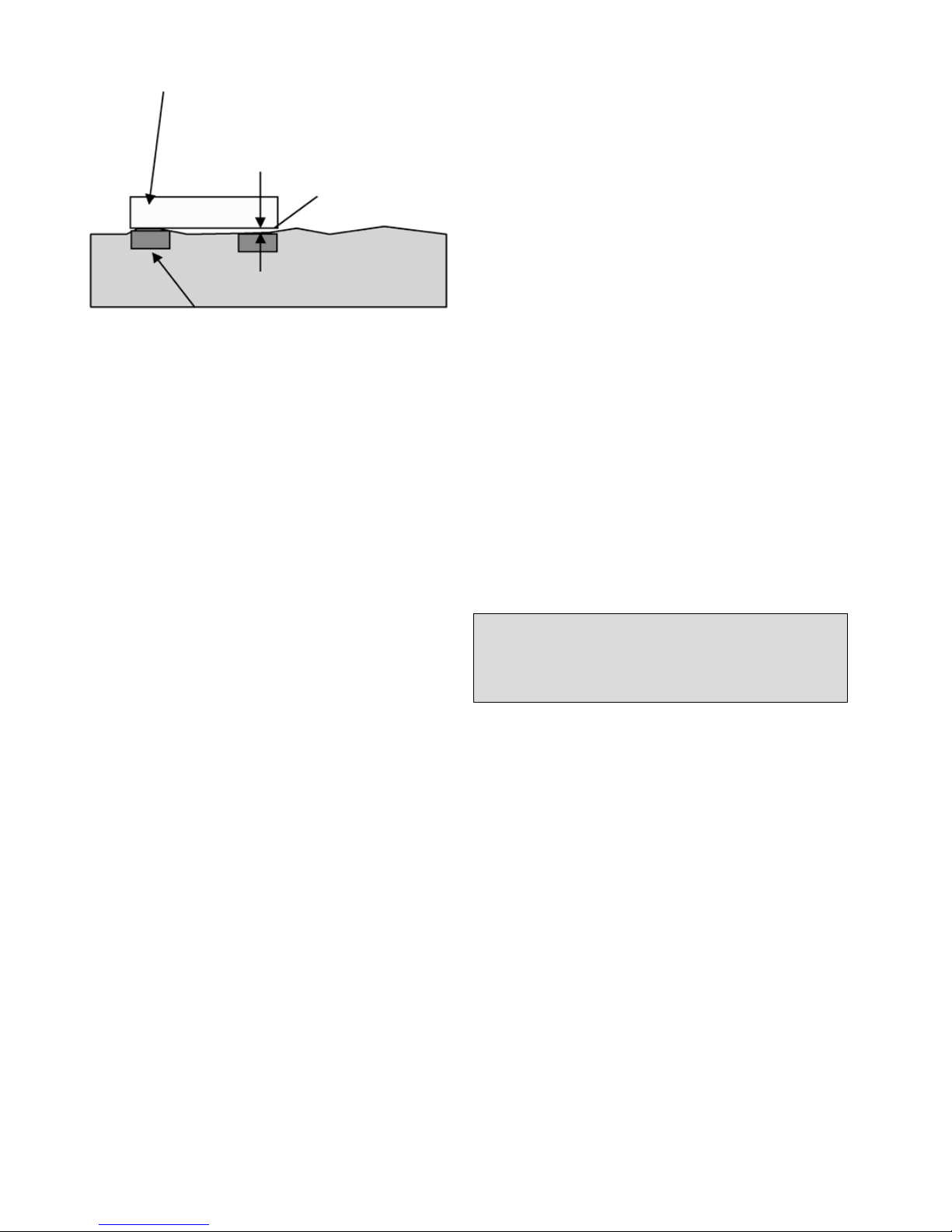
DE-26 ABB Motors and Generators | Low voltage motor manual 01-2009
3.4 Auswuchten und Anbau
von Kupplungshälften
und Riemenscheiben
Das Auswuchten des Motors erfolgte standardgemäß mit
halber Passfeder.
Beim Auswuchten mit ganzer Passfeder wird die Welle
mit einem GELBEN Aufkleber mit „Balanced with full key“
(Ausgewuchtet mit einer ganzen Passfeder) markiert.
Im Fall des Auswuchtens ohne Passfeder wird die Welle
mit einem BLAUEN Aufkleber mit „Balanced without key“
(Ausgewuchtet ohne Passfeder) markiert.
Kupplungshälften oder Riemenscheiben müssen nach
dem Einfräsen der Passfedernut ausgewuchtet werden.
Das Auswuchten muss entsprechend der für den Motor
angegebenen Auswuchtmethode erfolgen.
Kupplungshälften und Riemenscheiben dürfen nur mit
geeigneter Ausrüstung und Werkzeug auf der Welle
montiert werden, damit die Lager und Dichtungen nicht
beschädigt werden.
Montieren Sie niemals eine Kupplungshälfte oder
Riemenscheibe durch Schläge mit dem Hammer. Bei der
Demontage darf nie ein Hebel gegen das Motorgehäuse
angesetzt werden.
3.5 Einbau und Ausrichtung
des Motors
Stellen Sie für eine ungehinderte Luftströmung sicher,
dass genügend Abstand um den Motor vorhanden ist.
Die Mindestanforderungen für den Freiraum hinter der
Abdeckung des Motorgebläses sind im Produktkatalog
oder in den Maßzeichnungen angegeben, die im Web
verfügbar sind: siehe www.abb.com/motors&drives.
Die sorgfältige Ausrichtung ist von entscheidender
Bedeutung für das Vermeiden von Lagerschäden,
Schwingungen und möglichen Brüchen der Wellenenden.
Den Motor mit geeigneten Bolzen oder Ankerschrauben
montieren und zwischen Fundament und Füßen
Distanzscheiben einsetzen.
Hinweis: Der Höhenunterschied zwischen den
Flächen darf ± 0,1mm nicht
überschreiten.
Richtscheit mit
Wasserwaage
Fußposition
Mit geeigneten Methoden den Motor ausrichten.
Gegebenenfalls die Positionsbohrungen durchführen und
die Positionsbolzen an ihren Positionen befestigen.
Einbaugenauigkeit der Kupplungshälfte: prüfen, dass das
Spiel b weniger als 0,05 mm beträgt und dass der Abstand
a1 zu a2 ebenso unter 0,05 mm liegt. Siehe Abb. 3.
Ausrichtung nach endgültigem Festziehen der Bolzen oder
Ankerschrauben erneut prüfen.
Die in den Produktkatalogen angegebenen zulässigen
Lastwerte der Lager dürfen nicht überschritten werden.
3.6 Spannschienen
und Riementriebe
Die Befestigung des Motors auf den Spannschienen erfolgt
wie in Abb. 2 angegeben.
Die Spannschienen sind horizontal und auf gleicher Höhe
zu montieren.
Darauf achten, dass die Motorwelle parallel zur
Antriebswelle verläuft.
Riemen müssen gemäß der Anleitung des Lieferanten
der angetriebenen Komponente gespannt werden.
Beachten Sie jedoch die maximal zulässigen Riemenkräfte
(bzw. Radialkraftbelastungen der Lager), die Sie den
entsprechenden Produktkatalogen entnehmen können.
WARNUNG
Übermäßige Riemenspannung führt zur
Beschädigung der Lager und kann den Bruch
der Welle zur Folge haben!
3.7 Motoren mit Kondenswasser Ablaufstopfen
Sicherstellen, dass Kondenswasseröffnungen und
Kondenswasserstopfen nach unten zeigen.
Motoren mit verschließbaren Ablauföffnungen aus
Kunststoff werden in geöffnetem Zustand geliefert.
In sehr staubhaltigen Umgebungen müssen alle
Kondenswasseröffnungen verschlossen werden.
3.8 Kabel und elektrische
Anschlüsse
Der Verteilerkasten von eintourigen Standardmotoren
enthält in der Regel sechs Anschlussklemmen und
zumindest eine Erdungsklemme.
Zusätzlich zu den Klemmen der Hauptwicklung und der
Erdung kann der Klemmenkasten auch Anschlüsse für
Kaltleiter, Heizelemente oder anderes Zubehör enthalten.
Page 27

Low voltage motor manual 01-2009 | ABB Motors and Generators DE-27
Für die Anschlüsse aller Hauptkabel sind geeignete
Kabelschuhe zu verwenden. Kabel für Zubehör können
ohne weitere Vorrichtungen an den entsprechenden
Klemmenleisten angeschlossen werden.
Die Motoren sind nur für ortsfeste Installation
vorgesehen. Sofern nicht anders angegeben, weisen
Kabeleinführungsgewinde metrische Maße auf. Die IPKlasse der Kabelverschraubung muss mindestens der IPKlasse des Klemmenkastens entsprechen.
Nicht benutzte Kabeleinführungen sind entsprechend IPKlasse des Klemmenkastens mit Verschlusselementen zu
versehen.
Schutzart und Durchmesser sind in den Unterlagen zur
Kabelverschraubung spezifiziert.
WARNUNG
Geeignete Kabelverschraubungen und
Dichtungen in den Kabeleinführungen
entsprechend Typ und Durchmesser des Kabels
verwenden.
Weitere Information zu geeigneten Kabeln und
Verschraubungen für drehzahlgeregelte Motoren gibt es ab
Kapitel 5.5.
Die Erdung sollte vor dem Anschließen der Versorgungsspannung im Einklang mit den jeweils gültigen Vorschriften
erfolgen.
Stellen Sie sicher, dass der Motorschutz den jeweiligen
Umgebungs- und Witterungsbedingungen entspricht, z. B.
dass kein Wasser in den Motor oder die Klemmenkästen
eindringen kann.
Zur Gewährleistung der richtigen IP-Klasse müssen die
Dichtungen von Klemmenkästen sorgfältig in die hierfür
vorgesehenen Schlitze eingesetzt werden.
3.8.1 Anschlüsse für unterschiedliche
Startmethoden
Der Klemmenkasten von eintourigen Standardmotoren
enthält in der Regel sechs Anschlussklemmen und
zumindest eine Erdungsklemme. Dies ermöglicht Starts mit
Netzbetrieb oder Stern-/Dreieckanlauf. Siehe Abb. 1.
Bei polumschaltbaren und Spezialmotoren sind die
entsprechenden Angaben im Klemmenkasten oder im
Motorhandbuch zu beachten.
Spannung und Anschlussart sind auf dem Tyenschild
angegeben.
Netzbetrieb-Anlauf (DOL):
Y- oder D-Wicklungsanschlüsse können benutzt werden.
Zum Beispiel 690 VY, 400 VD bedeutet ein Y-Anschluss für
690 V und ein D-Anschluss für 400 V.
Stern-/Dreieckanlauf (Y/D):
Bei Verwendung eines D-Anschlusses muss die
Versorgungsspannung die gleiche wie die Nennspannung
des Motors sein.
Alle Verbindungslaschen an der Klemmenleiste sind zu
entfernen.
Andere Startverfahren und widrige Startbedingungen:
Ist beabsichtigt, andere Startmethoden zu benutzen, wie
etwa einen Softstarter, oder sind die Startbedingungen
besonders problematisch, wenden Sie sich bitte zuerst an
ABB.
3.8.2 Anschlüsse von Zubehör
Wenn ein Motor mit Kaltleitern oder anderen WDFs
(Pt100, Thermorelais usw.) und Zubehör ausgestattet
ist, müssen diese mit geeigneten Methoden verwendet
und angeschlossen werden. Auf der Innenseite des
Klemmenkastens befinden sich die Anschlussschaltbilder
für die Hilfselemente.
Die maximale Messspannung für die Kaltleiter beträgt
2,5 V. Der maximale Messstrom für Pt100 beträgt 5 mA.
Die Verwendung einer höheren Messspannung oder
eines höheren Messstroms kann zu Messfehlern oder
Systemschäden führen.
Die Wärmesensoren verfügen über eine BasisWicklungsisolierung. Beim Anschluss der Sensoren an
Steuersysteme usw. muss die angemessene Isolation oder
Isolierung gewährleistet sein, siehe IEC 60664.
HINWEIS!
Gewährleisten Sie den Isolationspegel oder die
Isolierung des Kaltleiter-Auslösegeräts, siehe IEC
60664.
3.9 Anschlussklemmen und
Drehrichtung
Von der Wellenstirnfläche auf das Antriebsende des
Motors gesehen dreht die Welle im Uhrzeigersinn, und die
Schaltphasensequenz – L1, L2, L3 – wird wie in Abb. 1
gezeigt an die Klemmen angeschlossen.
Durch Umpolen der Zuleitungskabel kann die Drehrichtung
geändert werden.
Falls der Motor einen Ein-Weg-Lüfter hat, sicherstellen,
dass er in Pfeilrichtung dreht (Pfeil am Motor angebracht).
Page 28

DE-28 ABB Motors and Generators | Low voltage motor manual 01-2009
4. Betrieb
4.1 Verwendung
Sofern auf dem Leistungsschild nicht anders angegeben,
sind die Motoren für folgende Bedingungen ausgelegt.
- Umgebungstemperaturbereich von -20 °C bis +40 °C.
- Maximale Aufstellungshöhe 1.000 m über NN.
- Die Toleranz beträgt gemäß EN/IEC 60034-1 (2004) ±5 %
für die Versorgungsspannung und ±2 % für die Frequenz.
Der Motor darf nur für zweckbestimmte
Anwendungen eingesetzt werden. Die Nennwerte
und Betriebsbedingungen werden auf den Motorleistungsschildern angegeben. Zudem müssen alle
Anforderungen in diesem Handbuch und weitere
entsprechende Anweisungen und Normen erfüllt und
befolgt werden.
Werden diese Grenzen überschritten, müssen Motorund Konstruktionsdaten überprüft werden. Für weitere
Informationen wenden Sie sich bitte an ABB.
WARNUNG
Die Nichteinhaltung von Anweisungen oder der
Wartung des Geräts kann die Sicherheit und
damit den Einsatz der Anlage gefährden.
4.2 Kühlung
Es ist zu prüfen, ob der Motor ausreichend belüftet ist. Es
muss sichergestellt werden, dass Objekte in der Nähe oder
direkte Sonneneinstrahlung dem Motor keine zusätzliche
Wärme zuführen.
Bei Motoren mit Flanschanbau (z. B. B5, B35, V1)
sicherstellen, dass die Konstruktion eine ausreichende
Lüftung der Flanschaußenfläche erlaubt.
4.3 Sicherheitshinweise
Die Anlage darf nur durch qualifiziertes, mit Arbeitsschutz-,
Sicherheits- und den jeweiligen nationalen Vorschriften
vertrautes Fachpersonal installiert und betrieben werden.
Zur Unfallverhütung sind entsprechend den im betreffenden
Land geltenden Gesetzen und Bestimmungen bei
der Montage und beim Betrieb des Motors geeignete
Sicherheitseinrichtungen zu verwenden.
WARNUNG
Es dürfen keine Arbeiten an Motor, Anschlusskabeln oder Zubehör, wie Frequenzumrichtern,
Anlassern, Bremsen, Kaltleiterkabeln oder Heizelementen vorgenommen werden, wenn Spannung anliegt.
Die folgenden Warnhinweise sind zu beachten:
1. Nicht auf den Motor treten.
2. Im Normalbetrieb und besonders nach dem
Ausschalten können an der Außenfläche des
Motorgehäuses hohe Temperaturen auftreten!
3. Einige Anwendungen (z. B. bei Speisung des Motors
mit Frequenzumrichtern) können eine spezielle
Anleitung erfordern.
4. Auf rotierende Teile des Motors achten.
5. Unter Spannung stehende Klemmenkästen nicht
öffnen.
Page 29

Low voltage motor manual 01-2009 | ABB Motors and Generators DE-29
5. Drehzahlgeregelte Niederspannungsmotoren
5.1 Einführung
Dieser Teil des Handbuchs enthält zusätzliche
Anleitungen für Motoren, die in Bereichen mit Frequenzumrichterspeisung verwendet werden. Die Anleitungen
in diesem und anderen relevanten Handbüchern des
verwendeten Frequenzumrichters müssen beachtet
werden, um die Sicherheit und Verfügbarkeit des Motors zu
gewährleisten.
ABB behält sich vor, zusätzliche Informationen
anzufordern zwecks Prüfung der Eignung für bestimmte
Maschinentypen, die bei speziellen Anwendungen oder mit
speziellen Konstruktionsänderungen zum Einsatz kommen.
5.2 Wicklungsisolierung
Drehzahlgeregelte Antriebe verursachen an der Motorwicklung höhere Spannungsbelastungen als die sinusförmige Versorgung und somit muss die Wicklungsisolierung des Motors sowie der Filter am Umrichterausgang entsprechend der folgenden Angaben
dimensioniert sein.
5.2.1 Phase-zu-Phase-Spannung
Die maximal zulässigen Phase-zu-Phase-Spannungsspitzen in der Motorklemme als Funktion der Anstiegszeit
des Impulses werden in Abb. 1 dargestellt.
Die höchste Kurve „Spezialisolierung von ABB“ gilt für
Motoren mit einer speziellen Wicklungsisolierung für
Frequenzumrichterspeisung, Variantencode 405.
Auf alle anderen Motoren in diesem Handbuch trifft die
„Standardisolierung von ABB“ zu.
5.2.2 Phase-gegen-Erde-Spannung
Die zulässigen Phase-zu-Erde-Spannungsspitzen an
Motorklemmen betragen:
Standardisolierung Spannungsspitze 1300 V
Spezialisolierung Spannungsspitze 1800 V
5.2.3 Auswahl der Wicklungsisolierung
für ACS550- und ACS800 Frequenzumrichter
Bei ACS800- und ACS550-Frequenzumrichtern von
ABB mit Dioden-Einspeisungseinheit (ungesteuerte DCSpannung) können Wicklungsisolierung und Filter gemäß
der folgenden Tabelle ausgewählt werden:
Nennversorgungsspannung UN
des Umrichters
Erforderliche
Wicklungsisolierung
und Filter
U
N
≤ 500 V ABB Standardisolierung
U
N
≤ 600 V ABB Standardisolierung + dU/
dt-Filter
ODER
ABB Spezialisolierung
(Variantencode 405)
U
N
≤ 690 V ABB Spezialisolierung
(Variantencode 405)
UND
dU/dt-Filter am
Umrichterausgang
U
N
≤ 690 V
UND
Kabellänge > 150 m
ABB Spezialisolierung
(Variantencode 405)
Für weitere Informationen zu Frequenzumrichtern mit
gesteuerten Einspeiseeinheiten oder Widerstand-bremsung
wenden Sie sich bitte an ABB.
5.2.4 Auswahl der Wicklungs-isolierung mit
allen anderen Frequenzumrichtern
Die Spannungsbelastungen sind auf Werte unter den
zulässigen Grenzen zu begrenzen. Wenden Sie sich
an den Lieferanten des Systems, um die Sicherheit der
Anwendung zu gewährleisten. Bei der Dimensionierung des
Motors ist der Einfluss möglicher Filter zu berücksichtigen.
5.3 Wärmeisolierung
Die meisten Motoren, die in diesem Handbuch
behandelt werden, sind mit PTC-Thermistoren in
den Ständerwicklungen ausgestattet. Diese müssen
mit geeigneten Mitteln an den Frequenzumrichter
angeschlossen werden. Weitere Informationen finden Sie
im Kapitel 3.8.2.
Page 30

DE-30 ABB Motors and Generators | Low voltage motor manual 01-2009
5.4 Lagerströme
Es sind isolierte Lager oder Lagerkonstruktionen,
Gleichtaktfilter und geeignete Verkabelungs- und
Erdungsverfahren gemäß der folgenden Anweisungen zu
verwenden:
5.4.1 Verhindern von Lagerströmen bei
ACS800- und ACS550-Frequenz umrichtern von ABB
Bei ACS800- und ACS550-Frequenzumrichtern von ABB
mit Dioden-Einspeiseeinheit sind die folgenden Verfahren
zu verwenden, um schädliche Lagerströme in den Motoren
zu verhindern:
Nennleistung (Pn)
und / oder Baugröße (IEC)
Schutzmaßnahmen
Pn < 100 kW Keine Maßnahmen
erforderlich
Pn ≥ 100 kW
ODER
IEC 315 ≤ Baugröße ≤ IEC
355
Isoliertes Lager auf
Nichtantriebsseite
Pn ≥ 350 kW
ODER
IEC 400 ≤ Baugröße ≤ IEC
450
Isoliertes Lager auf
Nichtantriebsseite
UND
Gleichtaktfilter am
Umrichter
Es werden isolierte Lager mit aluminiumoxidbe-schichteten
Innen- und/oder Außenringen oder Keramikwälzkörpern
empfohlen. Aluminiumoxid-beschichtungen werden
außerdem mit einem Dichtungs-mittel behandelt, um das
Eindringen von Schmutz und Feuchtigkeit in die poröse
Beschichtung zu verhindern. Genaue Angaben zum Typ
der Lagerisolierung finden Sie auf dem Leistungsschild
des Motors. Das Ändern des Lagertyps oder der
Isolierungsmethode ohne die Genehmigung von ABB ist
untersagt.
5.4.2 Verhindern von Lagerströmen
bei allen anderen Umrichtern
Der Betreiber ist für den Schutz des Motors und der
angetriebenen Komponenten vor schädlichen Lagerströmen verantwortlich. Die Anweisungen in Kapitel 5.4.1
können als Richtlinie verwendet werden, doch kann ihre
Wirksamkeit nicht in allen Fällen gewährleistet werden.
5.5 Verkabelung, Erdung
und EMV
Um eine korrekte Erdung und Übereinstimmung mit allen
EMV-Richtlinien zu gewährleisten, müssen an Motoren über
30 kW abgeschirmte symmetrische Kabel angeschlossen
und EMV-Kabelverschraubungen, d. h. Verschraubungen
mit 360°-Schirmkontaktierung, verwendet werden. Auch
für kleinere Motoren werden symmetrische abgeschirmte
Kabel dringend empfohlen. Die 360°-Erdung an allen
Kabeleinführungen wie in den Anweisungen für die
Kabelverschraubungen vornehmen. Kabelabschirmungen
zu Bündeln verdrillen und an die nächste Erdungsklemme/Sammelschiene im Klemmenkasten, Frequenzumwandlerschrank usw. anschließen.
HINWEIS!
An allen Endpunkten, z. B. Motor, Frequenzumrichter, ggf. Sicherheitsschalter usw., müssen
ordnungsgemäße Kabelverschraubungen mit
360°-Masseverbindung verwendet werden.
Bei Motoren ab Baugröße IEC 280 ist ein zusätzlicher
Potenzialausgleich zwischen Motorgehäuse und
angetriebenen Komponenten erforderlich, sofern nicht
beide auf einem gemeinsamen Stahlfundament montiert
sind. In diesem Fall muss die Leitfähigkeit bei hoher
Frequenz der über das Stahlfundament vorhandenen
Verbindung überprüft werden, indem z. B. die Potentialdifferenz zwischen den Komponenten gemessen werden.
Weitere Informationen über die Erdung und Verkabelung
bei drehzahlgeregelten Antrieben finden Sie im Handbuch
„Erdung und Verkablung des Antriebssystems“ (Code:
3AFY 61201998).
5.6 Betriebsdrehzahl
Für Drehzahlen über der auf dem Leistungsschild des
Motors angegebenen Nenndrehzahl sicherstellen, dass die
höchste zulässige Drehzahl des Motors oder die kritische
Drehzahl der gesamten Anwendung nicht überschritten
wird.
5.7 Dimensionierung des
drehzahlgeregelten Motors
5.7.1 Allgemeines
Bei Frequenzumrichtern von ABB kann das Dimensionieren
mithilfe der Belastbarkeitskurven in Absatz 5.8.2 oder
mithilfe des Dimensionierungs-programms DriveSize von
ABB erfolgen. Das Tool kann von der ABB Website (www.
abb.com/motors&generators) heruntergeladen werden.
Für Anwendungen, die durch andere Frequenzumrichter
gestützt werden, muss die Dimensionierung manuell
erfolgen. Für weitere Informationen wenden Sie sich bitte
an ABB.
Die Belastbarkeitskurven basieren auf der Nennversorgungsspannung. Der Betrieb bei Unter- oder
Überspannung kann die Leistung der Anwendung
beeinflussen.
5.7.2 Dimensionierung von
ACS800-Frequenz-umrichtern
mit DTC-Regelung
Die Belastbarkeitskurven in Abb. 4a - 4d gelten
für ACS800-Frequenzumrichter von ABB mit
ungesteuerter DC-Spannung und DTC-Steuerung. Die
Abbildungen stellen das ungefähre maximal zulässige
dauerhafte Ausgangsdrehmoment der Motoren als
Page 31

Low voltage motor manual 01-2009 | ABB Motors and Generators DE-31
Funktion der Versorgungsspannungsfrequenz dar.
Das Ausgangsdrehmoment wird als Prozentsatz des
Nenndrehmoments des Motors angegeben. Die Werte
sind nur indikativ, genaue Werte sind auf Anfrage erhältlich.
HINWEIS!
Die Höchstdrehzahl des Motors darf nicht
überschritten werden!
5.7.3 Dimensionierung von
ABB ACS550-Umrichtern
Die Belastbarkeitskurven in Abb. 5a - 5d gelten
für ACS550-Frequenzumrichter von ABB. Die
Abbildungen stellen das ungefähre maximal zulässige
dauerhafte Ausgangsdrehmoment der Motoren als
Funktion der Versorgungsspannungsfrequenz dar.
Das Ausgangsdrehmoment wird als Prozentsatz des
Nenndrehmoments des Motors angegeben. Die Werte sind
nur indikativ, genaue Werte sind auf Anfrage erhältlich.
HINWEIS!
Die Höchstdrehzahl des Motors darf nicht
überschritten werden!
5.7.4 Dimensionierung anderer
pulsweitenmodulierten
Spannungszwischenkreisumrichter
Für andere Frequenzumrichter mit ungesteuerter DCSpannung und einer Mindestschaltfrequenz von 3 kHz
kann die Dimensionierungsanleitung des ACS550 als
Richtlinie verwendet werden, es sollte aber beachtet
werden, dass die tatsächliche Wärmebelastbarkeit auch
niedriger sein kann. Wenden Sie sich an den Hersteller des
Frequenzumrichters oder den Lieferanten des Systems.
HINWEIS!
Die tatsächliche Wärmebelastbarkeit eines
Motors kann geringer als durch die Richtlinienkurven angegeben sein.
5.7.5 Kurzzeitige Überlasten
ABB-Motoren können normalerweise kurzfristig überlastet
und im Aussetzbetrieb verwendet werden. Die bequemste
Art der Dimensionierung solcher Anwendungen ist die
Verwendung des Tools DriveSize.
5.8 Leistungsschilder
Die Verwendung von ABB-Motoren mit drehzahlge-regelten
Anwendungen erfordert gewöhnlich keine zusätzliche
Leistungsschilder, und die Parameter zur Inbetriebnahme
des Frequenzumrichters sind auf dem Hauptleistungsschild
enthalten. Für einige Spezialanwendungen können
Motoren jedoch mit zusätzlichen Leistungsschildern für
drehzahlgeregelte Anwendungen ausgestattet sein, die
folgende Informationen enthalten:
- Drehzahlbereich
- Leistungsbereich
- Spannungs- und Strombereich
- Drehmomenttyp (konstant oder quadratisch)
- Frequenzumrichtertyp und erforderliche
Mindestschaltfrequenz
5.9 Inbetriebnahme des
drehzahlgeregelten Antriebs
Die Inbetriebnahme des drehzahlgeregelten Motors muss
gemäß den Anweisungen für den Frequenzumrichter und
den lokalen Gesetzen und Vorschriften erfolgen. Die durch
die Anwendung gesetzten Anforderungen und Grenzen
sind ebenfalls zu berücksichtigen.
Alle zum Einrichten des Frequenzumrichters erforderlichen
Parameter müssen den Motorleistungsschildern
entnommen werden. Die am häufigsten benötigten
Parameter lauten:
- Nennspannung des Motors
- Nennstrom des Motors
- Nennfrequenz des Motors
- Nenndrehzahl des Motors
- Nennleistung des Motors
HINWEIS!
Bei fehlenden oder ungenauen Daten den Motor
nicht in Betrieb nehmen, bevor die korrekten
Einstellungen gewährleistet sind.
ABB empfiehlt die Verwendung aller geeigneten
Schutzfunktionen des Frequenzumrichters, um die
Sicherheit der Anwendung zu erhöhen. Frequenzumrichter
bieten in der Regel z. B. folgende Funktionen (Namen und
Verfügbarkeit der Funktionen hängen von Hersteller und
Modell des Frequenzumrichters ab):
- Mindestdrehzahl
- Höchstdrehzahl
- Zeit für Beschleunigung und Abbremsung
- Maximaler Strom
- Maximales Drehmoment
- Blockierschutz
Page 32

DE-32 ABB Motors and Generators | Low voltage motor manual 01-2009
6. Wartung
WARNUNG
Auch bei Stillstand des Motors können
gefährliche Spannungen für die Versorgung
von Heizelementen oder für eine direkte
Wicklungsheizung anliegen.
WARNUNG
Der Kondensator in Einphasenmotoren kann
Ladung enthalten, die über den Motorklemmen
auftritt, auch wenn der Motor zum Stillstand
gekommen ist.
WARNUNG
Ein Motor mit Frequenzumrichterspeisung kann
auch im Stillstand Spannung erzeugen.
6.1 Allgemeine Kontrolle
1. Untersuchen Sie den Motor in regelmäßigen Abständen,
mindestens einmal pro Jahr. Die Häufigkeit der Kontrollen
hängt z. B. von der Feuchtigkeit der Umge-bungsluft
und von den lokalen Wetterverhältnissen ab. Sie sind
auf experimentellem Wege zu ermitteln und dann genau
einzuhalten.
2. Halten Sie den Motor sauber und sorgen Sie für einen
freien Kühlluftstrom. Beim Einsatz des Motors in einer
staubigen Umgebung ist es zu empfehlen, das Belüftungssystem regelmäßig zu überprüfen und zu reinigen.
3. Den Zustand der Wellendichtungen untersuchen (z. B.
V-Ring oder Radialdichtung); bei Bedarf neue Dichtungen
einsetzen.
4. Überprüfen Sie den Zustand aller Verbindungen und
Verbindungselemente (z. B. Schrauben).
5. Den Lager-Zustand untersuchen: auf ungewöhnliche
Geräusche achten, Schwingung und Lagertemperatur
messen, Kontrolle des verbrauchten Schmierfetts
oder Lager-Überwachung über SPM. Die Lager
erfordern eine besondere Aufmerksamkeit, wenn deren
Nennlebensdauer abläuft.
Wenn Anzeichen von Abnutzung festgestellt werden,
den Motor auseinanderbauen, die Teile kontrollieren und
erforderlichenfalls auswechseln. Die originalen Lager dürfen
nur durch Lager gleichen Typs ersetzt werden. Desgleichen
müssen neue Wellendichtungen von derselben Qualität sein
und die gleichen Eigenschaften wie die Originaldichtungen
aufweisen.
Wenn ein IP 55-Motor mit geschlossenem Kondenswasserloch-Stopfen geliefert wurde, sollten die Kondenswasserloch-Stopfen in regelmäßigen Abständen geöffnet
werden, um sicherzustellen, dass der Kondenswasserabfluss nicht blockiert ist und das Kondensat entweichen
kann. Dies muss aus Sicherheitsgründen bei abgestelltem
Motor durchgeführt werden.
6.1.1 Bereitschaft von Motoren
Wenn sich der Motor längere Zeit auf einem Schiff oder
in einer anderen Umgebung befindet, in der Vibrationen
auftreten, müssen folgende Maßnahmen ergriffen werden:
1. Die Welle muss durch Starten des Systems regelmäßig
alle 2 Wochen gedreht werden. (Dies ist zu dokumentieren.) Wenn aus irgendeinem Grund kein Starten möglich
ist, ist die Welle zumindest von Hand zu drehen, um sie
einmal pro Woche in eine andere Position zu bringen.
Vibrationen, die durch Ausrüstung anderer Fahrzeuge
verursacht werden, führen zu Lochfraß in den Lagern,
was durch regelmäßigen Betrieb / Drehen von Hand minimiert werden muss.
2. Das Lager muss einmal im Jahr gedreht und dabei geschmiert werden. (Dies ist zu dokumentieren.) Wenn
der Motor am Antriebsende über ein Kugellager verfügt,
muss vor dem Drehen der Welle die Transportsicherung
entfernt werden. Die Transportsicherung muss für einen
eventuellen Transport wieder angebracht werden.
3. Alle möglichen Vibrationen sind zu vermeiden, um Fehler
an den Lagern zu vermeiden. Außerdem müssen alle Anweisungen im Bedienungshandbuch für Inbetriebnahme
und Wartung des Motors befolgt werden. Die Garantie
deckt keine Schäden an Winden und Lagern ab, wenn
diese Anweisungen nicht befolgt wurden.
6.2 Schmierung
WARNUNG
Vorsicht bei allen rotierenden Teilen.
WARNUNG
Viele Fette können Hautreizungen sowie
Entzündungen des Auges verursachen. Befolgen
Sie alle Sicherheitshinweisen des Herstellers.
Lagertypen sind in den entsprechenden Produktkatalogen
spezifiziert und auf dem Leistungsschild aller unserer
Motoren mit Ausnahme der Motoren mit den kleinsten
Baugrößen angegeben.
Für Lagerschmierintervalle ist Zuverlässigkeit von
entscheidender Bedeutung. ABB verwendet für die
Schmierung das L
1
-Prinzip (d. h. dass 99 % der Motoren
die Nennlebensdauer erreichen).
6.2.1 Maschinen mit dauergeschmierten
Lagern
Lager sind im Allgemeinen dauergeschmierte Lager vom
Typ 1Z, 2Z, 2RS oder äquivalentem Typ.
Als Faustregel kann eine angemessene Schmierung für
Größen bis zu 250 gemäß L
10
für die folgende Dauer
erreicht werden.
Betriebsstunden für dauergeschmierte Lager bei einer
Umgebungstemperatur von 25 und 40°:
Page 33

Low voltage motor manual 01-2009 | ABB Motors and Generators DE-33
Schmierfristen gemäß dem L10-Prinzip
Baugröße Pole
Betriebsstunden
bei 25° C
Betriebsstunden
bei 40° C
56-63 2-8 40 000 40 000
71 2 40 000 40 000
71 4-8 40 000 40 000
80-90 2 40 000 40 000
80-90 4-8 40 000 40 000
100-112 2 40 000 32 000
100-112 4-8 40 000 40 000
132 2 40 000 27 000
132 4-8 40 000 40 000
160 2 40 000 36 000
160 4-8 40 000 40 000
180 2 38 000 38 000
180 4-8 40 000 40 000
200 2 27 000 27 000
200 4-8 40 000 40 000
225 2 23 000 18 000
225 4-8 40 000 40 000
250 2 16 000 13 000
250 4-8 40 000 39 000
Daten gelten bei 50 Hz, bei 60 Hz Werte um 20 %
reduzieren.
Diese Werte gelten für die zulässigen Lastwerte im
Produktkatalog. Für Abhängigkeiten von Anwendungsund Lastbedingungen siehe den entsprechenden
Produktkatalog oder wenden Sie sich an ABB.
Für die Betriebsstunden bei vertikal aufgestellten Motoren
sind die o. g. Werte jeweils zu halbieren.
6.2.2 Motoren mit nachschmierbarem
Lager
Informationsschild für Schmierung und allgemeiner
Ratgeber zur Schmierung
Ist die Maschine mit einem Informationsschild für
Schmierung versehen, sind die dort angegebenen Werte zu
befolgen.
Auf dem Schild können die Schmierintervalle bezüglich
Einbau, Umgebungstemperatur und Drehzahl bestimmt
sein.
Beim ersten Start oder nach einer Lagerschmierung
kann für ca. 10 bis 20 Stunden ein temporärer
Temperaturanstieg auftreten.
Einige Motoren sind mit einem Sammler für Altfett
ausgerüstet. Entsprechend die Anweisung für diese
Einrichtung befolgen.
A. Manuelle Schmierung
Nachschmieren bei laufendem Motor
– Den Stopfen der Schmiermittel-Auslassöffnung abneh-
men oder das Sperrventil öffnen, falls vorhanden.
– Sicherstellen, dass der Schmierkanal offen ist.
– Die vorgesehene Menge Schmierfett in das Lager
einspritzen.
– Den Motor 1-2 Stunden laufen lassen, um
sicherzustellen, dass sämtliches überschüssiges Fett
aus dem Lager gedrückt ist. Den Stopfen der Fett-
Auslassöffnung oder ggf. Sperrventil schließen.
Nachschmieren bei stillstehendem Motor
Falls es nicht möglich ist, die Lager bei laufendem Motor
nachzuschmieren, kann auch bei stillstehender Maschine
geschmiert werden.
– In diesem Fall nur die Hälfte der Fettmenge benutzen,
anschließend den Motor für einige Minuten bei voller
Drehzahl laufen lassen.
– Nachdem der Motor abgestellt ist, den Rest der
vorgesehenen Fettmenge in das Lager drücken.
– Nach 1-2 Stunden Durchlauf die Fett-Auslassöffnung
verschließen oder das Sperrventil, falls vorhanden,
schließen.
B. Automatische Schmierung
Bei automatischer Schmierung muss die Fett-Auslassöffnung beständig offen sein, bzw. das Sperrventil, falls
vorhanden, geöffnet sein.
ABB empfiehlt dringend den Einsatz elektromechanischer
Anlagen.
Bei Benutzung eines automatischen Nachschmier-systems
sind die in der Tabelle angegebenen Werte für Schmierfett
pro Schmierintervall zu vervierfachen.
Wenn 2-polige Motoren automatisch nachgeschmiert
werden, befolgen Sie bitte die entsprechenden Schmierempfehlungen im Kapitel über Schmiermittel.
6.2.3 Schmierintervalle und -mengen
Als Faustregel kann eine angemessene Schmierung für
Motoren mit nachschmierbaren Lagern gemäß L1 für die
folgende Dauer erreicht werden. Für Informationen über
den Betrieb bei höherer Umgebungstemperatur bitte an
ABB wenden. Die Faustformel zum Ändern der L1-Werte in
L10-Werte: L10 = 2,7 x L1.
Für vertikal montierte Motoren sind die Nachschmierintervalle in der folgenden Tabelle zu halbieren.
Die Schmierintervalle basieren auf einer Umgebungstemperatur von +25°C. Ein Anstieg der Umgebungstemperatur lässt die Temperatur der Lager entsprechend
ansteigen. Bei einem Anstieg von 15 °C sollten die Werte
halbiert, bei einem Absinken um 15 °C können sie verdoppelt werden.
Bei drehzahlgeregeltem Betrieb (d.h. Frequenzumrichterspeisung) muss die Lagertemperatur für den gesamten
Betriebsbereich gemessen werden, und wenn sie 80°C
überschreitet, sollten die Schmierintervalle für einen Anstieg
um 15°C der Lagertemperatur halbiert werden. Wenn der
Motor bei hohen Geschwindigkeiten betrieben wird, können auch so genannte Hochgeschwindigkeitsschmiermittel
verwendet werden, siehe Kapitel 6.2.4.
WARNUNG
Die zulässige Höchsttemperatur für Lager und
Schmierfett von +110 °C darf nicht überschritten
werden.
Die Höchstdrehzahl, für die der Motor ausgelegt ist,
darf nicht überschritten werden.
Page 34

DE-34 ABB Motors and Generators | Low voltage motor manual 01-2009
Schmierfristen gemäß dem L1-Prinzip
Bau-
größe
Fett-
menge
g/Lager
kW
3600
U/min
3000
U/min
kW
1800
U/min
1500
U/min
kW
1000
U/min
kW
500-900
U/min
Kugellager
Nachschmierintervalle in Betriebsstunden
112 10 alle 10000 13000 alle 18000 21000 alle 25000 alle 28000
132 15 alle 9000 11000 alle 17000 19000 alle 23000 alle 26500
160 25 ≤ 18,5 9000 12000 ≤ 15 18000 21500 ≤ 11 24000 alle 24000
160 25 > 18,5 7500 10000 > 15 15000 18000 > 11 22500 alle 24000
180 30 ≤ 22 7000 9000 ≤ 22 15500 18500 ≤ 15 24000 alle 24000
180 30 > 22 6000 8500 > 22 14000 17000 > 15 21000 alle 24000
200 40 ≤ 37 5500 8000 ≤ 30 14500 17500 ≤ 22 23000 alle 24000
200 40 > 37 3000 5500 > 30 10000 12000 > 22 16000 alle 20000
225 50 ≤ 45 4000 6500 ≤ 45 13000 16500 ≤ 30 22000 alle 24000
225 50 > 45 1500 2500 > 45 5000 6000 > 30 8000 alle 10000
250 60 ≤ 55 2500 4000 ≤ 55 9000 11500 ≤ 37 15000 alle 18000
250 60 > 55 1000 1500 > 55 3500 4500 > 37 6000 alle 7000
280
1)
60 alle 2000 3500 - - - - - - -
280
1)
60 - - - alle 8000 10500 alle 14000 alle 17000
280 35 alle 1900 3200 - - - -
280 40 - - alle 7800 9600 alle 13900 alle 15000
315 35 alle 1900 3200 - - - -
315 55 -
-
alle 5900 7600 alle 11800 alle 12900
355 35 alle 1900 3200 - - - -
355 70 -
-
alle 4000 5600 alle 9600 alle 10700
400 40 alle 1500 2700 - - - -
400 85 - - alle 3200 4700 alle 8600 alle 9700
450 40 alle 1500 2700 - - - -
450 95 - - alle 2500 3900 alle 7700 alle 8700
Rollenlager
Nachschmierintervalle in Betriebsstunden
160 25 ≤ 18,5 4500 6000 ≤ 15 9000 10500 ≤ 11 12000 alle 12000
160 25 > 18,5 3500 5000 > 15 7500 9000 > 11 11000 alle 12000
180 30 ≤ 22 3500 4500 ≤ 22 7500 9000 ≤ 15 12000 alle 12000
180 30 > 22 3000 4000 > 22 7000 8500 > 15 10500 alle 12000
200 40 ≤ 37 2750 4000 ≤ 30 7000 8500 ≤ 22 11500 alle 12000
200 40 > 37 1500 2500 > 30 5000 6000 > 22 8000 alle 10000
225 50 ≤ 45 2000 3000 ≤ 45 6500 8000 ≤ 30 11000 alle 12000
225 50 > 45 750 1250 > 45 2500 3000 > 30 4000 alle 5000
250 60 ≤ 55 1000 2000 ≤ 55 4500 5500 ≤ 37 7500 alle 9000
250 60 > 55 500 750 > 55 1500 2000 > 37 3000 alle 3500
280
1)
60 alle 1000 1750 - - - - - - -
280
1)
70 - - - alle 4000 5250 alle 7000 alle 8500
280 35 alle 900 1600 - - - -
280 40 - - alle 4000 5300 alle 7000 alle 8500
315 35 alle 900 1600 - - - -
315 55
- -
alle 2900 3800 alle 5900 alle 6500
355 35 alle 900 1600 - - - -
355 70
- -
alle 2000 2800 alle 4800 alle 5400
400 40 alle - 1300 - - - -
400 85 - - alle 1600 2400 alle 4300 alle 4800
450 40 alle - 1300 - - - -
450 95 - - alle 1300 2000 alle 3800 alle 4400
1) M3AA
Für die Motoren M4BP 160 bis 250 kann das Intervall um bis zu 30 % erhöht werden, jedoch höchstens über drei
Kalenderjahre.
Die Werte der Tabelle oben gelten auch für die Größen M4BP 280 bis 355.
Page 35

Low voltage motor manual 01-2009 | ABB Motors and Generators DE-35
6.2.4 Schmiermittel
WARNUNG
Verschiedene Fetttypen nicht miteinander
vermischen.
Ungeeignete Schmiermittel können die Lager
beschädigen.
Für die Nachschmierung darf nur ein speziell auf die
Schmierung von Kugellagern abgestimmtes Fett mit den
folgenden Eigenschaften verwendet werden:
– Hochwertiges Fett mit Lithiumkomplexseife und
Mineral- oder PAO-Öl
– Viskosität des Grundöls 100-160 cST bei 40 °C
– Konsistenz NLGI Bereich 1.5 - 3 *)
– Dauergebrauchstemperatur -30°C - +120°C
*) Für vertikal montierte Motoren und unter heißen
Betriebsbedingungen ist ein steiferer NLGI Grad zu
empfehlen.
Die oben angegebene Schmierfettspezifikation gilt für
Umgebungstemperaturen über -30 °C oder unter +55 °C
und Lagertemperaturen unter 110 °C. Wenden Sie sich
andernfalls an ABB für Informationen über geeignetes
Schmierfett.
Geeignete Fette mit den geforderten Eigenschaften sind bei
allen größeren Schmiermittelherstellern erhältlich.
Beimengungen werden empfohlen, doch sollte man
eine schriftliche Garantie vom Schmiermittelhersteller
besonders für EP-Zusätze erhalten, dass diese
nicht die Lager beschädigen oder innerhalb des
Betriebstemperaturbereichs die Eigenschaften der
Schmiermittel beeinträchtigen.
WARNUNG
Schmiermittel, denen EP-Zusätze beigemengt
sind, sind unter hohen Lager-Temperaturen bei
Baugrößen von 280 bis 450 nicht zu empfehlen.
Folgende hochwertige Schmierfette können benutzt
werden:
- Esso Unirex N2 oder N3 (Lithiumkomplex-Basis)
- Mobil Mobilith SHC 100 (Lithiumkomplex-Basis)
- Shell Gadus S5 V 100 2 (Lithiumkomplex-Basis)
- Klüber Klüberplex BEM 41-132 (Spezielle Lithiumbasis)
- FAG Arcanol TEMP110 (Lithiumkomplex-Basis)
- Lubcon Turmogrease L 802 EP PLUS
(Spezielle Lithiumbasis)
- Total Multiplex S 2 A (Lithiumkomplexbasis)
HINWEIS!
Stets Hochgeschwindigkeitsfette verwenden
für 2-polige Maschinen mit hoher Drehzahl,
bei denen der Drehzahlfaktor höher als
480.000 ist (berechnet als Dm x n, wobei
Dm = durchschnittlicher Lagerdurchmesser
in mm; n = Drehzahl U/min). Das
Hochgeschwindigkeitsschmiermittel wird auch für
die Motortypen M2CA, M2FA, M2CG und M2FG,
Baugröße 355 bis 400, 2-polige Maschinen
verwendet.
Folgende Schmierfette können mit Graugussmotoren mit
hoher Drehzahl verwendet werden, dürfen jedoch nicht mit
Schmierfetten auf Lithiumkomplex-Basis gemischt werden:
- Klüber Klüber Quiet BQH 72-102 (Polyuretan-Basis)
- Lubcon Turmogrease PU703 (Polyuretan-Basis)
Falls andere Schmiermittel verwendet werden, erkundigen
Sie sich bitte beim Hersteller, ob die Qualität der der
oben aufgeführten Fette entspricht. Die Schmierintervalle
basieren auf den oben aufgeführten hochwertigen
Schmierfetten. Bei Verwendung anderer Schmierfette
können sich die Intervalle verringern.
Wenden Sie sich an ABB, wenn die Kompatibilität des
Schmiermittels unsicher ist.
Page 36

DE-36 ABB Motors and Generators | Low voltage motor manual 01-2009
7. Kundendienst
7.1 Ersatzteile
Bei der Bestellung von Ersatzteilen sollte die Motorseriennummer, die vollständige Typenbezeichnung und der
Produktkode (siehe Leistungsschild) angegeben werden.
Weitere Informationen finden Sie auf unserer Website unter
www.abb.com/partsonline.
7.2 Neuwicklung
Neuwicklungen dürfen nur in autorisierten Werkstätten
durchgeführt werden.
Brandgas-Entlüftungsmotoren und andere Spezial-motoren
sollten nicht ohne Rücksprache mit ABB neugewickelt
werden.
7.3 Lager
Die Lager sind mit besonderer Sorgfalt zu behandeln.
Die Lager dürfen nur mit Hilfe von Ausziehwerkzeugen
demontiert und in erwärmtem Zustand oder unter
Verwendung von Spezialwerkzeug eingebaut werden.
Der Austausch von Lagern wird in einer eigenen
Hinweisschrift von ABB ausführlich beschrieben.
8. Umweltanforderungen
8.1 Geräuschpegel
Die meisten ABB Motoren haben einen Schalldruckpegel,
der 82 dB(A) bei 50 Hz nicht überschreitet.
Konkrete Werte für die einzelnen Maschinen sind dem
jeweiligen Produktkatalog zu entnehmen. Bei 60 Hz
sinusförmige Versorgung sind die Werte ca. 4 dB(A) höher
als die 50 Hz-Werte in den Produktkatalogen.
Bzgl. des Schalldruckpegels bei Frequenzumrichterspeisung setzen Sie sich bitte mit ABB in Verbindung.
Die Schalldruckpegel für alle Maschinen mit eigenen
Kühlsystemen und für die Reihen M2F*/M3F*, M2L*/
M3L*, M2R*/M3R*, M2BJ/M3BJ und M2LJ/M3LJ sind in
gesonderten Handbüchern angegeben.
Page 37

Low voltage motor manual 01-2009 | ABB Motors and Generators DE-37
9. Fehlerbehebung
In den folgenden Anleitungen kann nicht auf sämtliche technische Einzelheiten oder Unterschiede zwischen den
verschiedenen Motoren oder alle bei der Installation, beim Betrieb oder bei der Wartung möglicherweise auftretenden
Situationen eingegangen werden. Anfragen bezüglich weitergehender Informationen richten Sie bitte an die nächste ABBVertriebsstelle.
Motor-Fehlersuchtabelle
Wartungs- und etwaige Fehlersuchmaßnahmen am Motor dürfen nur von hierfür qualifiziertem Personal und mit
geeigneten Werkzeugen und Hilfsmitteln durchgeführt werden.
FEHLER URSACHE MASSNAHMEN
Motor startet nicht Sicherungen durchgebrannt Neue Sicherungen des richtigen Typs und mit entsprechenden
Bemessungsdaten einsetzen.
Überlastauslösung Überlast in Anlasser prüfen und zurücksetzen.
Fehlerhafte Stromversorgung Überprüfen, ob die Stromversorgung den Angaben auf dem
Motorleistungsschild entspricht und für den jeweiligen Lastfaktor
geeignet ist.
Fehlerhafte Netzanschlüsse Anschlüsse anhand des mit dem Motor gelieferten Schaltplans
überprüfen.
Stromkreisunterbrechung in Wicklung
oder Steuerschalter
Erkennbar an einem Summen bei Einschalten des Schalters.
Verdrahtung auf lockere Anschlüsse überprüfen.
Auch kontrollieren, ob alle Kontakte schließen.
Mechanischer Fehler Überprüfen, ob Motor und Antrieb frei drehen. Lager und Schmierung
kontrollieren.
Ständerkurzschluss Schlechter
Anschluss an Ständerwicklung
Erkennbar an durchgebrannten Sicherungen. Motor muss neu
gewickelt werden. Lagerschilde abnehmen; Fehler lokalisieren.
Defekter Rotor Auf gebrochene Stäbe oder Endringe kontrollieren.
Motor überlastet Last reduzieren.
Motor läuft nicht Phasenausfall Leitungen auf offene Phase kontrollieren.
Falsche Anwendung Nach Rücksprache mit dem Anbieter des Geräts geeigneten Typ bzw.
geeignete Baugröße verwenden.
Überlast Last reduzieren.
Unterspannung Kontrollieren, ob die auf dem Leistungsschild angegebene Spannung
eingehalten wird. Anschluss überprüfen.
Offener Stromkreis Durchgebrannte Sicherungen; Überlastrelais, Ständer und Drucktasten
prüfen.
Motor läuft nur für
kurzen Zeitraum
Netzausfall Auf lose Anschlüsse zum Netz, zu den Sicherungen und zur Steuerung
überprüfen.
Motor läuft nicht
hoch
Falsche Anwendung Durch Rücksprache mit dem Lieferanten des Geräts geeigneten Typ
bestimmen.
Unterspannung an Motorklemmen
durch Netzspannungsabfall
Höhere Spannung oder höhere Transformatorstufe verwenden oder
Last reduzieren. Anschlüsse überprüfen. Leitungen auf angemessenen
Querschnitt überprüfen.
Anlauflast zu hoch Anlauflast des Motors prüfen.
Gebrochene Rotorstäbe oder lockerer
Rotor
Kontrollieren, ob in der Nähe der Ringe Risse vorhanden sind.
Möglicherweise wird ein neuer Rotor benötigt, da eine dauerhafte
Reparatur in diesem Fall meist nicht möglich ist.
Offener Primärkreis Fehler mit Prüfgerät lokalisieren und beheben.
Page 38

DE-38 ABB Motors and Generators | Low voltage motor manual 01-2009
FEHLER URSACHE MASSNAHMEN
Motor läuft zu langsam
hoch und/oder zieht zu
starken Strom
Last zu hoch Last reduzieren.
Spannung beim Anlauf zu niedrig Auf zu hohen Widerstand überprüfen. Angemessenen
Leitungsquerschnitt verwenden.
Defekter Käfigrotor Neuen Rotor einbauen.
Netzspannung zu niedrig Spannungsversorgung klären.
Falsche Drehrichtung Falsche Phasenfolge Anschlüsse am Motor bzw. an der Schalttafel vertauschen.
Motor überhitzt bei Betrieb
unter Last
Überlast Last reduzieren.
Belüftungsöffnungen sind möglicher-weise
durch Schmutz verstopft und verhindern
eine ordnungsgemäße Kühlung des
Motors
Belüftungsöffnungen säubern und kontrollieren, ob ein
kontinuierlicher Luftstrom den Motor kühlt.
Eine Motorphase ist möglicherweise
ausgefallen
Kontrollieren, ob alle Leitungen richtig angeschlossen sind.
Erdschluss Motor muss neu gewickelt werden
Unsymmetrische Klemmenspannung Anschlussleitungen, Anschlüsse und Transformatoren auf
Fehler überprüfen.
Motorschwingungen Motor schlecht ausgerichtet Motor nachrichten.
Mangelnde Stabilität des Unterbaus Unterbau verstärken.
Unwucht in Kupplung Kupplung auswuchten.
Unwucht in getriebener Anlage Getriebene Anlage neu auswuchten.
Defekte Lager Lager austauschen.
Lager schlecht ausgerichtet Motor reparieren.
Auswuchtgewichte verschoben Motor neu auswuchten.
Wuchtung von Rotor und Kupplung nicht
aufeinander abgestimmt (Halbkeil- bzw.
Vollkeilwuchtung)
Kupplung oder Motor neu auswuchten.
Mehrphasenmotor läuft einphasig Auf offenen Stromkreis überprüfen.
Axialspiel zu groß Lager nachstellen oder Feder-Ausgleichsscheibe einlegen.
Geräusche Lüfter reibt an Lüfterkappe Lüftermontage korrigieren.
Lockerer Sitz auf Grundplatte Fußschrauben anziehen.
Betriebsgeräusch zu laut Luftspalt nicht gleichmäßig Lagerschildbefestigung bzw. Lager überprüfen und
entsprechend korrigieren.
Unwucht im Rotor Rotor neu auswuchten.
Lagertemperatur zu hoch Welle verbogen oder beschädigt Welle richten oder austauschen.
Riemenzug zu stark Riemenspannung reduzieren.
Riemenscheiben zu weit von
Wellenschulter entfernt
Riemenscheibe näher am Motorlager anordnen.
Durchmesser der Riemenscheiben zu
klein
Größere Riemenscheiben verwenden.
Schlechte Ausrichtung Durch Nachrichten des Antriebs korrigieren.
Unzureichendes Schmierfett Angemessene Qualität des im Lager vorhandenen
Schmierfetts sicherstellen.
Qualität des Schmierfetts beeinträchtigt
oder Schmiermittel verschmutzt
Altes Schmierfett entfernen. Lager gründlich in Kerosin
waschen und mit neuem Fett schmieren.
Überschüssiges Schmiermittel Schmiermittelmenge verringern; das Lager sollte maximal
zur Hälfte gefüllt sein.
Lager überlastet Ausrichtung, Radial- und Axialschub überprüfen.
Defekte Kugel oder raue Laufbahnen Lager austauschen; vor dem Einbau des neuen Lagers das
Lagergehäuse gründlich reinigen.
Page 39

Low voltage motor manual 01-2009 | ABB Motors and Generators FR-39
1. Introduction ............................................................................................................................................41
1.1 Déclaration de Conformité ................................................................................................................41
1.2 Validité .............................................................................................................................................41
2. Manutention ...........................................................................................................................................42
2.1 Contrôle à la réception .....................................................................................................................42
2.2 Transport et entreposage .................................................................................................................42
2.3 Levage .............................................................................................................................................42
2.4 Masse de la machine .......................................................................................................................42
3. Installation et mise en service ..............................................................................................................43
3.1 Généralités .......................................................................................................................................43
3.2 Mesure de la résistance de l'isolation ...............................................................................................43
3.3 Fondations .......................................................................................................................................43
3.4 Équilibrage et mise en place des demi-accouplements et des poulies ..............................................44
3.5 Montage et alignement du moteur ................................................................................................... 44
3.6 Glissières et entraînements à courroie ............................................................................................. 44
3.7 Moteurs avec trous de purge pour eaux de condensation ............................................................... 44
3.8 Câblage et connexions électriques .................................................................................................. 45
3.8.1 Couplages pour les différentes méthodes de démarrage ...................................................... 45
3.8.2 Connections des éléments auxiliaires ................................................................................... 45
3.9 Bornes et sens de rotation .............................................................................................................. 45
4. Opération ............................................................................................................................................... 46
4.1 Utilisation ........................................................................................................................................ 46
4.2 Refroidissement .............................................................................................................................. 46
4.3 Sécurité .......................................................................................................................................... 46
5. Moteurs basse tension à vitesse variable .......................................................................................... 47
5.1 Introduction ..................................................................................................................................... 47
5.2 Isolation du bobinage ...................................................................................................................... 47
5.2.1 Tensions phase-phase ......................................................................................................... 47
5.2.1 Tensions phase-terre ............................................................................................................ 47
5.2.3 Sélection de l'isolation du bobinage pour les convertisseurs ACS550- et ACS800- .............. 47
5.2.4 Sélection de l'isolation du bobinage avec tous les autres convertisseurs .............................. 47
Moteurs basse tension
Manuel d'installation, d'exploitation, de maintenance et de sécurité
Table des matières Page
Page 40

FR-40 ABB Motors and Generators | Low voltage motor manual 01-2009
5.3 Protection thermique des bobinages ............................................................................................... 47
5.4 Courants de paliers ......................................................................................................................... 48
5.4.1 Élimination des courants de paliers
avec les convertisseurs ABB ACS550 et ACS800 ................................................................ 48
5.4.2 Elimination des courants des roulements avec les autres convertisseurs .............................. 48
5.5 Câblage, mise à la terre et CEM ...................................................................................................... 48
5.6 Vitesse de fonctionnement .............................................................................................................. 48
5.7 Dimensionnement du moteur pour application avec variateur de vitesse ......................................... 48
5.7.1 Généralités ........................................................................................................................... 48
5.7.2 Dimensionnement avec convertisseurs ABB ACS800 et contrôle DTC ................................. 49
5.7.3 Dimensionnement avec convertisseurs ABB ACS550 .......................................................... 49
5.7.4 Dimensionnement avec d'autres convertisseurs PWM de source de tension ........................ 49
5.7.5 Surcharges de courte durée ................................................................................................. 49
5.8 Plaques signalétiques ...................................................................................................................... 49
5.9 Mise en service de l'application avec variateur ................................................................................ 49
6. Maintenance .......................................................................................................................................... 50
6.1 Entretien ......................................................................................................................................... 50
6.1.1 Moteurs en attente .................................................................................................................50
6.2 Lubrification .................................................................................................................................... 50
6.2.1 Machines avec roulements graissés à vie ............................................................................. 51
6.2.2 Moteurs avec roulements regraissables ................................................................................ 51
6.2.3 Intervalles de lubrification et quantités de lubrifiant ............................................................... 51
6.2.4 Lubrifiants ............................................................................................................................ 54
7. Service après vente .............................................................................................................................. 55
7.1 Pièces détachées ............................................................................................................................ 55
7.2 Rebobinage .................................................................................................................................... 55
7.3 Roulements ..................................................................................................................................... 55
8. Contraintes d'environnement .............................................................................................................. 55
8.1 Niveaux sonores ............................................................................................................................. 55
9. Dépannage ............................................................................................................................................ 56
Page 41

Low voltage motor manual 01-2009 | ABB Motors and Generators FR-41
1. Introduction
Remarque !
Les présentes consignes doivent être suivies
afin d'assurer une installation, une exploitation
et une maintenance correctes de la machine. Le
personnel chargé de l'installation, l'exploitation ou
la maintenance de la machine ou de l'équipement
associé devra en être informé. La machine
doit être installée et exploitée par un personnel
qualifié, connaissant les règles de protection et de
sécurité, ainsi que la réglementation en vigueur.
Le non-respect de ces instructions peut entraîner
l'annulation des garanties applicables.
1.1 Déclaration de Conformité
Les déclarations de conformité au titre de la directive Basse
Tension 73/23/CEE modifiée par la directive 93/68 CEE
sont fournies séparément avec chaque machine.
La déclaration de conformité satisfait également les
exigences de la certification d'incorporation au titre de la
directive Machine 98/37/CEE, Art 4.2
Annexe II, sub B
1.2 Validité
Cette notice technique s'applique aux machines électriques
ABB de types suivants, utilisées en modes moteur et
générateur.
séries MT*, MXMA,
séries M2A*/M3A*, M2B*/M3B*, M4B*, M2C*/M3C*,
M2F*/M3F*, M2L*/M3L*, M2M*/M3M*, M2Q*,
M2R*/M3R*, M2V*/M3V*
en hauteurs d'axe 56 - 450.
Une notice technique séparée existe pour les autres types
de moteurs, comme par exemple les moteurs de sécurité
Ex: " Moteurs basse tension pour atmosphères explosives:
Manuel d'installation, d'exploitation et de maintenance "
(réf. Low Voltage Motors/Manual for Ex-motors).
Des consignes supplémentaires sont nécessaires pour
certains types de machine en raison de spécificités
d'application et/ou de considérations de conception.
Des consignes supplémentaires sont disponibles pour les
moteurs suivants :
– moteurs pour table à rouleaux
– moteurs refroidis à l'eau
– moteurs de protection IP 23
– moteurs de désenfumage
– moteurs freins
– moteurs pour températures ambiantes élevées
Page 42

FR-42 ABB Motors and Generators | Low voltage motor manual 01-2009
2. Manutention
2.1 Contrôle à la réception
A la réception, vérifiez l'état du moteur (bouts d'arbre,
brides et surfaces peintes) ; tout dommage doit être signalé
immédiatement au transporteur.
Vérifiez toutes les données de la plaque signalétique, plus
particulièrement la tension et le mode de couplage des
enroulements (étoile ou triangle). Le type de roulement
est spécifié sur la plaque signalétique des moteurs, à
l'exception de ceux de faible hauteur d'axe.
2.2 Transport et entreposage
Le moteur doit toujours être entreposé dans un local fermé
(température ambiante supérieure à –20 °C), à l'abri de
l'humidité et de la poussière, et exempt de vibrations. Lors
du transport, tout choc, chute et présence d'humidité
doit être évité. Si d'autres conditions de transport sont
imposées, veuillez contacter ABB.
Les surfaces usinées non protégées (bouts d'arbre
et brides) doivent être recouvertes d'une protection
anticorrosion.
Nous préconisons de tourner l'arbre à la main à intervalles
réguliers pour prévenir tout écoulement de graisse.
L'utilisation de chauffages anti-condensation est
recommandée afin d'éviter toute condensation d'eau dans
le moteur.
Le moteur ne doit pas être soumis à des vibrations
supérieures à 0,5 mm/s à l'arrêt afin d'éviter tout
endommagement des roulements.
Pendant le transport ou tout déplacement, le rotor des
moteurs dotés de roulements à rouleaux cylindriques et/
ou à contact oblique doit être immobilisé par un dispositif
adéquat.
2.3 Levage
Tous les moteurs ABB dont le poids est supérieur à 25 kg
sont équipes d'anneaux de levage.
Seuls les anneaux de levage principaux du moteur doivent
être utilisés pour son levage. Ils ne doivent en aucun cas
servir à soulever le moteur lorsque celui-ci est fixé à un
autre équipement.
Les anneaux de levage pour éléments auxiliaires (freins,
ventilateurs de refroidissement séparés) ou boîtes à bornes
ne doivent pas être utilisés pour lever le moteur.
Les moteurs de même hauteur d'axe peuvent présenter
un centre de gravité distinct du fait de leur différence en
termes de puissance et de position de montage, et de la
présence d'équipements auxiliaires différents.
Les anneaux de levage endommagés ne doivent pas être
utilisés. Vérifiez que les anneaux de levage intégrés ne sont
pas endommagés avant le levage.
Les anneaux de levage doivent être serrés avant le levage.
Au besoin, la position de chaque boulon sera ajustée au
moyen de rondelles (entretoises) appropriées.
Vérifiez la compatibilité de l'engin de levage et de la taille
des crochets avec les anneaux de levage.
Veillez à ne pas endommager les équipements auxiliaires et
les câbles raccordés au moteur.
2.4 Masse de la machine
La masse totale des machines de même hauteur d'axe
peut varier selon leur puissance, leur disposition de
montage et les auxiliaires montés.
Le tableau suivant donne la masse maximale approximative
des machines en exécution de base et en fonction du
matériau du châssis.
La masse réelle de tous les moteurs ABB (excepté les
moteurs dotés des plus petits châssis (56 et 63)) est
indiquée sur leur plaque signalétique.
Hauteur
d'axe
Aluminium
Poids
kg
Fonte
Poids
kg
Acier
Poids
kg
Ajouter
pour le
frein
56 4.5 - 63 6 - 71 8 13 5
80 12 20 8
90 17 30 10
100 25 40 16
112 36 50 20
132 63 90 30
160 95 130 30
180 135 190 45
200 200 275 55
225 265 360 75
250 305 405 75
280 390 800 600 315 - 1700 1000 355 - 2700 2200 400 - 3500 3000 450 - 4500 - -
Page 43

Low voltage motor manual 01-2009 | ABB Motors and Generators FR-43
3. Installation et mise en service
AVERTISSEMENT
Avant toute intervention, débranchez et
désaccouplez le moteur ou la machine entraînée.
3.1 Généralités
Toutes les valeurs de la plaque signalétique afférentes à
la certification doivent être soigneusement vérifiées, pour
vous assurer que les branchements et la protection du
moteur sont réalisés correctement.
AVERTISSEMENT
En cas de moteurs montés avec l'arbre orienté
vers le haut et si de l'eau ou des liquides
peuvent couler le long de l'arbre, l'utilisateur doit
envisager de monter des moyens pour éviter
l'écoulement.
Le cas échéant, retirez le dispositif d'immobilisation utilisé
pour le transport. Tournez l'arbre à la main pour vérifier que
sa rotation s'effectue sans entrave.
Moteurs dotés de roulements à rouleaux :
La rotation du moteur sans charge radiale appliquée à
l'arbre est susceptible d'endommager le roulement à
rouleaux.
Moteurs dotés de roulements à contact oblique :
La rotation du moteur, sans charge axiale appliquée
sur l'arbre dans la direction adéquate, est susceptible
d'endommager le roulement à contact oblique.
AVERTISSEMENT
Pour les machines à roulements à rouleaux
cylindriques, la force axiale ne doit, en aucune
manière, changer de direction.
Le type de roulements est spécifié sur la plaque
signalétique du moteur.
Moteurs dotés de graisseurs :
Lors du démarrage du moteur pour la première fois ou
après un entreposage de longue durée, appliquez la
quantité de graisse spécifiée.
Pour de plus amples informations, consultez la section
"6.2.2 Moteurs dotés de roulements regraissables".
3.2 Mesure de la résistance
de l'isolation
La résistance de l'isolation du moteur doit être mesurée
avant sa mise en service et en particulier si les bobinages
sont susceptibles d'être humides.
AVERTISSEMENT
Avant toute intervention, débranchez et
désaccouplez le moteur ou la machine entraînée.
La résistance de l'isolation, corrigée à 25 °C, doit dépasser
la valeur de référence, càd. 100 MΩ (mesurée avec 500
ou 1000 V CC). La valeur de la résistance de l'isolation est
réduite de moitié chaque fois que la température ambiante
augmente de 20 °C.
AVERTISSEMENT
La carcasse du moteur doit être mis à la terre,
et les câblages doivent être déchargés contre la
carcasse immédiatement après chaque mesure
afin d'éviter tout risque de choc électrique.
Si vous n'obtenez pas la valeur de résistance de référence,
les bobinages sont trop humides. Ils doivent alors être
séchés en étuve, à une température de 90 °C pendant
12 à 16 heures, puis à 105 °C pendant 6 à 8 heures.
Pendant le séchage, vous devez retirer les obturateurs
des trous de purge et ouvrir les valves de fermeture, si le
moteur en est doté. N'oubliez pas de les refermer après le
séchage. Même si les bouchons de purge sont fixés, il est
recommandé de démonter les flasques et couvercles de
boîtes à bornes pour l'opération de séchage.
Les bobinages imprégnés d'eau de mer doivent
normalement être rebobinés.
3.3 Fondations
La préparation du support de fixation (fondations) du
moteur incombe entièrement à l'utilisateur final.
Les supports métalliques doivent être traités contre la
corrosion.
Les fondations doivent être à niveau, voir schéma cidessous, et suffisamment rigides pour encaisser les effets
de courts-circuits. Elles doivent être d'une conception
et de dimensions permettant d'éviter tout transfert de
vibration au moteur, ainsi que toute vibration provoquée par
résonance.
Page 44

FR-44 ABB Motors and Generators | Low voltage motor manual 01-2009
3.4 Equilibrage et mise en place
des demi-accouplements
et des poulies
En configuration standard, l'équilibrage du moteur est
réalisé à l'aide d'une demi-clavette.
En cas d'équilibrage avec une clavette entière, l'arbre
porte une étiquette de couleur JAUNE, avec la mention
« Balanced with full key ».
En cas d'équilibrage sans clavette, l'arbre porte une
étiquette de couleur BLEUE avec la mention « Balanced
without key ».
Les demi-accouplement et poulies doivent être équilibrés
après usinage de rainure de clavette. L'équilibrage doit être
effectué conformément aux instructions d'équilibrage du
moteur.
Les demi-accouplements et les poulies doivent être
montés sur l'arbre à l'aide de dispositifs et d'outils adaptés
pour ne pas endommager les roulements et les éléments
d'étanchéité.
N'utilisez jamais de marteau pour mettre en place un demiaccouplement ou une poulie et ne les démontez jamais en
utilisant un levier appuyé sur le châssis du moteur.
3.5 Montage et alignement
du moteur
Veillez à laisser un espace libre suffisant autour du moteur
pour permettre le passage de l'air. Les exigences requises
en termes d'espace libre derrière le couvercle du ventilateur
du moteur peuvent être consultées dans le catalogue des
produits ou via les schémas de dimensionnement présents
sur le Web : voir www.abb.com/motors&generators.
Remarque ! La différence de
niveau maximale entre les
emplacements des pattes
du moteur ne doit pas
excéder ± 0,1 mm.
Règle
Emplacement des pattes
L'alignement doit être parfait pour éviter toute détérioration
des roulements, les vibrations et les ruptures éventuelles
des arbres.
Montez le moteur sur ses fondations à l'aide des boulons
et goujons appropriés et placez des cales entre les
fondations et les pieds.
Alignez le moteur à l'aide de la méthode appropriée.
Le cas échéant, forez des trous de positionnement et fixez
des goupilles de positionnement.
Précision de montage du demi-accouplement : vérifiez que
le jeu b est inférieur à 0,05 mm et que l'écart entre a1 et a2
est également inférieur à 0,05 mm. Consultez la figure 3.
Revérifiez l'alignement après le serrage final des boulons et
goujons.
Ne pas dépasser les valeurs de charge admissibles des
roulements spécifiées dans les catalogues de produits.
3.6 Glissières et entraînements
à courroie
Fixez le moteur sur les glissières comme le montre la
Figure 2.
Disposez les glissières horizontalement, à la même hauteur.
Assurez-vous que l'arbre du moteur est parallèle à l'arbre
d'entraînement.
Les courroies doivent être tendues conformément
aux instructions du fournisseur ou de l'équipement
d'entraînement. Ne dépassez cependant pas les valeurs de
tension maximales des courroies (c'est-à-dire, les efforts
radiaux maximaux admissibles par les roulements) figurant
dans les catalogues de produits correspondants.
AVERTISSEMENT
Une courroie trop tendue peut endommager les
roulements et l'arbre.
3.7 Moteurs avec trous de purge
pour eaux de condensation
Vérifiez que les trous et bouchons de purge sont orientés
vers le bas.
Les machines équipées de trous de purge à obturateurs
sont livrées en position ouverte. Dans les environnements
très poussiéreux, tous les trous de purge doivent être
fermés.
Page 45

Low voltage motor manual 01-2009 | ABB Motors and Generators FR-45
3.8 Câblage et connexions
électriques
La boîte à bornes des moteurs monovitesse standard
comporte normalement six bornes pour le bobinage et au
moins une borne de terre.
Outre les bornes principales d'alimentation électrique et la
borne de terre, la boîte à bornes peut également contenir
des raccordements pour des thermistances, des éléments
de réchauffage ou des équipements auxiliaires.
Des anneaux de câble appropriés doivent être utilisés pour
la connexion de tous les câbles principaux. Les câbles
pour éléments auxiliaires peuvent être connectés tels quels
dans leurs boîtes à bornes.
Les moteurs sont uniquement destinés à une installation
fixe. Sauf indication contraire, les filetages des entrées de
câble sont définis selon le système métrique. La classe IP
du presse-étoupe doit être au moins identique à celle des
boîtes à bornes.
Les entrées de câble inutilisées doivent être fermées à
l'aide d'éléments étanches conformes à la classe IP de la
boîte à bornes.
L'indice de protection et le diamètre sont spécifiés dans la
documentation technique du presse-étoupe.
AVERTISSEMENT
Utilisez des presse-étoupes et joints appropriés
dans les entrées de câble, conformément au type
et au diamètre du câble.
Des consignes supplémentaires sur les câbles et les
presse-étoupes adaptés aux applications à vitesse variable
sont disponibles dans le chapitre 5.5.
La mise à la terre doit être réalisée conformément à la
réglementation en vigueur avant raccordement de la
machine au réseau.
Assurez-vous que le mode de protection du moteur
correspond aux contraintes d'environnement et climatiques
(ex., le moteur ou la boîte à bornes est parfaitement
étanche à l'eau).
Les joints d'étanchéité de la boîte à bornes doivent être
placés correctement dans les fentes prévues à cet effet afin
de respecter la classe IP.
3.8.1 Couplages pour les différentes
méthodes de démarrage
La boîte à bornes des moteurs monovitesse standard
comporte normalement six bornes pour le bobinage et
au moins une borne de terre. Cela permet d'utiliser le
démarrage DOL ou Y/D. Cf. figure 1.
Pour les moteurs bivitesse et les moteurs spéciaux, les
raccordements électriques doivent être effectués selon les
instructions figurant à l'intérieur de la boîte à bornes ou
dans le manuel d'utilisation du moteur.
La tension et le mode de couplage sont indiqués sur la
plaque signalétique du moteur.
Démarrage direct sur le réseau :
Possibilité de couplage Y ou D.
Ex., 690 VY, 400 VD désigne un couplage Y pour 690 V et
un couplage D pour 400 V.
Démarrage étoile/triangle (Y/D) :
Lorsqu'un couplage D est utilisé la tension d'alimentation
doit être égale à la tension nominale du moteur.
Vous devez retirer toutes les barrettes de connexion situées
sur la plaque à bornes.
Autres modes de démarrage et démarrages
en conditions difficiles :
Lorsque d'autres méthodes de démarrage sont utilisées,
comme un démarreur progressif, ou si les conditions de
démarrage sont particulièrement difficiles, veuillez consulter
au préalable ABB.
3.8.2 Couplages des éléments auxiliaires
Si un moteur est équipé de thermistances ou autres RTD
(Pt100, relais thermiques, etc.) et équipement auxiliaires,
il est recommandé de les utiliser et de les connecter selon
des moyens appropriés. Les schémas de raccordement
des auxiliaires se trouvent dans la boîte à bornes.
La tension de mesure maximum pour les thermistances est
de 2,5 V. La tension de mesure maximum pour la Pt100 est
de 5 mA. L'application d'une tension ou d'un courant de
mesure supérieur(e) peut provoquer des erreurs de lecture
ou endommager le système.
L'isolation des capteurs thermiques à bobinage est de
type basique. Lors du branchement des capteurs aux
systèmes de commande, etc. assurez-vous que l'isolation
ou l'isolement est correct, voir IEC 60664.
Remarque!
Garantissez le niveau d'isolation du circuit de
thermistances, voir IEC 60664.
3.9 Bornes et sens de rotation
L'arbre tourne dans le sens des aiguilles d'une montre, vu
du côté accouplement du moteur, pour un ordre de phases
- L1, L2, L3 - aux bornes, comme le montre la figure 1.
Pour inverser le sens de rotation, permutez les deux
raccordements des câbles d'alimentation, au choix.
Si le moteur est doté d'un ventilateur unidirectionnel, vérifiez
que celui-ci tourne effectivement dans le sens indiqué par
la flèche figurant sur le moteur.
Page 46

FR-46 ABB Motors and Generators | Low voltage motor manual 01-2009
4. Opération
4.1 Utilisation
Les moteurs sont conçus pour les conditions d'utilisation
suivantes, sauf indication contraire sur la plaque
signalétique.
- Plage normale de températures ambiantes :
-20 °C à +40 °C.
- Altitude maximale : 1000 m au-dessus du niveau
de la mer.
- La tolérance pour la tension d'alimentation est de
±5 % et de ±2 % pour la fréquence, conformément
à la norme EN / CEI 60034-1 (2004).
Le moteur ne peut être utilisé que dans les applications
prévues à cet effet. Les valeurs nominales et conditions
d'utilisation sont indiquées sur les plaques signalétiques
du moteur. En outre, toutes les exigences du présent
manuel, autres instructions et normes annexes doivent être
respectées.
En cas de non-respect de ces limitations, les données
électriques et mécaniques du moteur doivent être vérifiées.
Veuillez contacter ABB pour de plus amples informations.
AVERTISSEMENT
Le fait d'ignorer toute instruction ou maintenance
de l'appareil peut en compromettre la sécurité,
empêchant son utilisation.
4.2 Refroidissement
Vérifiez que le moteur est correctement refroidi. Assurez
vous qu'aucun objet ne se trouve à proximité ou qu'aucun
rayonnement direct du soleil ne chauffent le moteur.
Pour les moteurs montés sur bride (par ex., B5, B35, V1),
assurez-vous que la structure permet un passage d'air
suffisant au niveau de la surface extérieure de la bride.
4.3 Sécurité
La machine doit être installée et exploitée par un personnel
qualifié, connaissant les règles de protection et de sécurité,
ainsi que la réglementation en vigueur.
Les dispositifs de sécurité obligatoires pour la prévention
des accidents sur les sites d'installation et d'exploitation
doivent être mis à disposition, conformément à la
réglementation en vigueur.
AVERTISSEMENT
Lorsque la tension est appliquée, ne réalisez pas
de travaux sur le moteur, de connexion de câbles
ou d'accessoires tels que des convertisseurs
de fréquence, des démarreurs, des freins,
des câbles de thermistances ou des éléments
chauffants.
Règles à respecter
1. Ne marchez pas sur le moteur.
2. Au toucher, la température de l'enveloppe extérieure
du moteur fonctionnant normalement, et spécialement
après son arrêt, peut être très élevée.
3. Certains modes de fonctionnement spéciaux des
moteurs exigent l’application de consignes particulières
(ex., alimentation par convertisseur de fréquence).
4. Faites attention aux pièces rotatives du moteur.
5. N'ouvrez pas les boîtes à bornes lorsqu'elles sont sous
tension.
Page 47

Low voltage motor manual 01-2009 | ABB Motors and Generators FR-47
5. Moteurs basse tension à vitesse variable
5.1 Introduction
Cette partie du manuel fournit des instructions
supplémentaires pour les moteurs utilisés avec une
alimentation par convertisseur de fréquence. Les
instructions fournies dans ce document et dans les
manuels correspondants du convertisseur de fréquence
sélectionné, doivent être respectées pour garantir la
sécurité et la disponibilité du moteur.
Des informations supplémentaires peuvent être requises
par ABB quant à l'adéquation de certains types de
machine utilisés pour certaines applications spécifiques ou
de conception spécialement modifiée.
5.2 Isolation du bobinage
Les variateurs de vitesse peuvent imposer aux bobinages
du moteur des niveaux de tension supérieurs à ceux
délivrés par un réseau d'alimentation sinusoïdal. C'est
pourquoi il faut dimensionner l'isolation du bobinage du
moteur et le filtre de sortie du convertisseur en suivant les
instructions suivantes.
5.2.1 Tensions phase-phase
Les pics de tension phase-phase maximum autorisés
dans la borne du moteur en tant que fonction du temps
de hausse de l'impulsion peuvent être consultés dans
la Figure 4.
La courbe la plus élevée "Isolation spéciale ABB"
s'applique aux moteurs équipés d'un système d'isolation
spécial pour l'alimentation avec convertisseur de fréquence
(code 405).
L' "Isolation standard ABB" s'applique à tous les moteurs
décrits dans le présent manuel.
5.2.2 Tensions phase-terre
Les pics de tension phase-terre autorisés au niveau des
normes du moteur sont :
Pic d'isolation standard de 1300 V
Pic d'isolation spéciale de 1800 V
5.2.3 Sélection de l'isolation du bobinage
pour les convertisseurs
ACS550- et ACS800
Dans le cas des systèmes d'entraînement uniques de
séries ABB ACS800- et ACS550- avec unité d'alimentation
à diode (tension CC non contrôlée), la sélection de
l'isolation du bobinage et des filtres peut se faire en
fonction du tableau ci-dessous :
Tension
d'alimentation
nominale UN du
convertisseur
Isolation du bobinage et
filtres nécessaires
U
N
≤ 500 V Isolation standard ABB
U
N
≤ 600 V Isolation standard ABB
+ Filtres dU/dt
OU
Isolation spéciale ABB
(code option 405)
U
N
≤ 690 V Isolation spéciale ABB
(code option 405)
ET
ltres dU/dt à la sortie
du convertisseur
U
N
≤ 690 V
ET
longueur de câble >
150 m
Isolation spéciale ABB
(code option 405)
Pour de plus amples informations concernant le freinage à
résistance et les convertisseurs avec unités d'alimentation
contrôlées, contactez ABB.
5.2.4 Sélection de l'isolation du bobinage
avec tous les autres convertisseurs
Les surtensions ne doivent pas excéder certaines limites
acceptables. Veuillez contacter le concepteur du système
pour garantir la sécurité de l'application. L'influence
des filtres éventuels doit être prise en compte lors du
dimensionnement du moteur.
5.3 Protection thermique
La plupart des moteurs décrits dans ce manuel sont
équipés de thermistances PTC dans les bobinages
du stator. Il est recommandé de les connecter au
convertisseur de fréquence par les moyens adaptés.
Reportez-vous également au chapitre 3.8.2.
Page 48

FR-48 ABB Motors and Generators | Low voltage motor manual 01-2009
5.4 Courants de paliers
Il faut utiliser des roulements et structures de roulement
isolées, des filtres en mode courant et un câblage
approprié, ainsi que des méthodes de mise à la terre
adéquates, conformément aux instructions suivantes :
5.4.1. Elimination des courants des
roulements avec les convertisseurs
ABB ACS800 et ACS550
Dans le cas des convertisseurs de fréquence de série
ABB ACS800 et ACS550 avec unité d'alimentation avec
diode, les méthodes suivantes doivent être utilisées pour
éviter des courants de roulement susceptibles d'altérer le
fonctionnement des moteurs
Puissance nominale (Pn)
et/ou hauteur d'axe (CEI)
Mesures préventives
Pn < 100 kW Aucune action
nécessaire
Pn ≥ 100 kW
OU
CEI 315 ≤ Frame size
≤ CEI 355
Roulement isolé côté
non-entraînement
Pn ≥ 350 kW
OU
CEI 400 ≤ Frame size
≤ CEI 450
Roulement isolé côté
non-entraînement
ET
Filtre en mode
commun au niveau du
convertisseur
Il est recommandé d'utiliser des roulement isolés dotés
d'alésages intérieur et/ou extérieur revêtus d'oxyde
d'aluminium ou d'éléments de roulement en céramique.
Les revêtements d'oxyde d'aluminium sont également
traités à l'aide d'un produit d'étanchéité qui empêche
la pénétration des impuretés et de l'humidité à travers
le revêtement poreux. Pour le type exact d'isolation de
roulement, reportez-vous à la plaque signalétique du
moteur. Il est interdit de modifier le type de roulement ou la
méthode d'isolation sans l'autorisation préalable d'ABB.
5.4.2 Elimination des courants des roule ments avec les autres convertisseurs
L'utilisateur est responsable de la protection du moteur
et de l'équipement d'entraînement contre les courants
de roulements dangereux. Les instructions décrites au
chapitre 5.4.1 peuvent être suivies, mais leur efficacité ne
peut être garantie dans tous les cas de figure.
5.5 Câblage, mise à la terre
et CEM
Pour assurer une mise à la terre correcte et garantir la
conformité avec toutes les normes CEM applicables, les
moteurs d'une puissance supérieure à 30 kW doivent
être câblés à l'aide de câbles symétriques blindés et de
presse-étoupe CEM assurant une continuité de masse sur
360°. Pour les moteurs de moindre puissance, l'utilisation
de câbles symétriques blindés est également hautement
recommandée. Procédez à la disposition de mise à la terre
pour toutes les entrées de câble en suivant les instructions
relatives aux presse-étoupes. Torsadez les blindages de
câble dans les faisceaux et connectez la borne/barre
omnibus la plus proche à l'intérieur de la boîte à bornes, à
l'armoire du convertisseur, etc.
Remarque !
Des presse-étoupes appropriés assurant une
continuité de masse sur 360° doivent être utilisés
au niveau de tous les points de raccordement
; par exemple, au niveau du moteur, du
convertisseur, de l'éventuel commutateur de
sécurité, etc.
Pour les moteurs d'une hauteur d'axe supérieure ou égale
à CEI 280, il est nécessaire de procéder à une égalisation
supplémentaire du potentiel entre le châssis du moteur et
l'équipement entraîné, sauf si le moteur et l'équipement
sont montés sur un même socle d'acier. Dans ce cas, la
conductivité haute fréquence de la connexion fournie par le
socle en acier doit être vérifiée, par exemple, en mesurant
la différence de potentiel entre les composants.
De plus amples informations concernant la mise à la
terre et le câblage des variateurs de vitesse peuvent être
consultées dans le manuel "Mise à la terre et câblage du
système d'entraînement" (code : 3AFY 61201998).
5.6 Vitesse de fonctionnement
Pour les vitesses supérieures à la vitesse nominale inscrite
sur la plaque signalétique du moteur ou dans le catalogue
produit correspondant, vérifiez l'absence de dépassement
de la vitesse de rotation la plus élevée autorisée ou de la
vitesse critique de l'ensemble de l'application.
5.7 Dimensionnement du moteur
pour application avec
variateur de vitesse
5.7.1 Généralités
Dans le cas des convertisseurs de fréquence d'ABB,
les moteurs peuvent être dimensionnés en utilisant le
programme de dimensionnement DriveSize d'ABB. L'outil
est téléchargeable sur le site Web d'ABB (www.abb.com/
motors&generators).
Pour les applications fournies avec d'autres convertisseurs,
les moteurs devront être dimensionnés manuellement. Pour
plus d'informations, contactez ABB.
Les courbes de capacité de charge sont basées sur la
tension d'alimentation nominale. Le fonctionnement dans
des conditions de sous-tension ou de surtension peuvent
influencer les performances de l'application.
Page 49

Low voltage motor manual 01-2009 | ABB Motors and Generators FR-49
5.7.2 Dimensionnement avec convertis seurs ABB ACS800 et contrôle DTC
Les courbes de capacité de charge présentées dans
les figures 4a - 4d sont valables pour les convertisseurs
ABB ACS800 avec une tension en courant continu non
contrôlée et un contrôle DTC. Les figures présentent
le couple de sortie continu maximum approximatif
des moteurs, en tant que fonction de la fréquence
d'alimentation. Le couple de sortie est fourni en
pourcentage du couple nominal du moteur. Les valeurs
sont fournies à titre indicatif. Les valeurs exactes sont
disponibles sur demande.
Remarque !
La vitesse maximale du moteur ne doit pas être
dépassée !
5.7.3 Dimensionnement avec
convertisseurs ABB ACS550
Les courbes de capacité de charge présentées dans
les figures 5a - 5d sont valables pour les convertisseurs
ABB ACS550. Les figures présentent le couple de sortie
continu maximum approximatif des moteurs, en tant que
fonction de la fréquence d'alimentation. Le couple de sortie
est fourni en tant que pourcentage du couple nominal
du moteur. Les valeurs sont fournies à titre indicatif. Les
valeurs exactes sont disponibles sur demande.
Remarque !
La vitesse maximale du moteur ne doit pas être
dépassée !
5.7.4 Dimensionnement avec d'autres
convertisseurs PWM de source
de tension
Pour les autres convertisseurs qui présentent une tension
en courant continu non contrôlée et une fréquence de
commutation minimale de 3 kHz, les instructions de
dimensionnement de l'ACS550 peuvent être utilisées
comme lignes directrices. Cependant, il faut noter que la
capacité de charge thermique réelle peut également être
inférieure. Veuillez contacter le fabricant du convertisseur
ou le fournisseur de système.
Remarque !
La capacité de charge thermique réelle d'un
moteur peut être inférieure à celle indiquée par
les courbes de capacité de charge de référence.
5.7.5 Surcharges de courte durée
Les moteurs ABB peuvent généralement être surchargés
de façon temporaire, ou bien être exploités de façon
intermittente. La méthode la plus adaptée pour
dimensionner ces applications est d'utiliser l'utilitaire
DriveSize.
5.8 Plaques signalétiques
L'utilisation des moteurs ABB dans des applications à
vitesse variable ne nécessitent généralement pas de
plaques signalétiques supplémentaires et les paramètres
nécessaires pour la mise en service du convertisseur
sont disponibles sur la plaque signalétique principale.
Cependant, dans certaines applications spéciales, les
moteurs peuvent être équipés de plaques signalétiques
supplémentaires pour les applications à vitesse variable.
Ces plaques contiennent les informations suivantes :
- plage de vitesses
- plage de puissances
- plage de tensions et de courants
- type de couple (constant ou quadratique)
- type de convertisseur et fréquence de commutation
minimale requise
5.9 Mise en service de
l'application avec variateur
La mise en service de l'application avec variateur doit
être effectuée conformément aux instructions d'utilisation
du convertisseur de fréquence et en respect des lois et
réglementations. Les exigences et limitations associées à
l'application doivent également être prises en compte.
Tous les paramètres nécessaires au réglage du
convertisseur doivent être associés aux éléments des
plaques signalétiques du moteur. Les paramètres les plus
fréquemment requis sont les suivants :
- Tension nominale du moteur
- Courant nominal du moteur
- Fréquence nominale du moteur
- Vitesse nominale du moteur
- Puissance nominale du moteur
Remarque !
En cas d'absence d'information ou d'imprécision,
n'utilisez le moteur qu'une fois vérifiée l'exactitude
des paramètres !
ABB recommande l'utilisation de l'ensemble des fonctionnalités proposées par le convertisseur afin d'optimiser la
sécurité de l'application. Les convertisseurs offrent généralement les fonctionnalités suivantes (les noms et disponibilité des fonctionnalités dépendent du fabricant et du modèle
de convertisseur) :
- Vitesse minimale
- Vitesse maximale
- Temps d'accélération et de décélération
- Courant maximal
- Couple maximal
- Protection contre les calages
Page 50

FR-50 ABB Motors and Generators | Low voltage motor manual 01-2009
6. Maintenance
AVERTISSEMENT
Même avec le moteur à l'arrêt, la boîte à bornes peut
être sous tension pour les résistances de réchauffage
ou le réchauffage direct des enroulements.
AVERTISSEMENT
La charge du condensateur des moteurs monophasés peut entretenir une tension sur les bornes
d ' a l i m e n t a t i o n , m ê m e s i l e m o t e u r a a t t e i n t l ' a r r ê t .
AVERTISSEMENT
Un moteur sous fonctionnement avec convertisseur
de fréquence peut être alimenté même si le moteur
est à l'arrêt.
6.1 Entretien
1. Vérifiez l'état du moteur à intervalles réguliers, au moins
une fois par an. La fréquence des contrôles dépend, par
exemple, du degré d'humidité de l'air ambiant et des
conditions climatiques spécifiques. La périodicité devra
donc être établie de manière empirique, pour ensuite être
respectée rigoureusement..
2. Le moteur doit toujours être propre et correctement ventilé.
En cas d'utilisation dans un environnement poussiéreux, le
système de ventilation doit être vérifié et nettoyé à intervalles
réguliers.
3. Vérifiez l'état des joints de l'arbre (ex., joint trapézoïdal ou
radial) et remplacez-les au besoin.
4. Vérifiez l'état des raccordements et du montage ainsi que
les vis de fixation.
5. Vérifiez l'état des roulements : bruit anormal, vibrations,
température, aspect de la graisse souillée (utilisation
éventuelle d'un dispositif de type SPM de surveillance
en continu de l'état des roulements et du comportement
vibratoire des machines). Faites spécialement attention
aux roulements lorsque le calcul de la durée de vie estimée
approche de l'échéance.
En cas de signes d'usure, démontez le moteur, vérifiez l'état
des pièces et remplacez les pièces défectueuses. Lors du
remplacement des roulements, les roulements de rechange
doivent être d'un type identique à celui des roulements placés
à l'origine. Les joints de l'arbre doivent être remplacés par des
joints de qualité et caractéristiques identiques aux roulements
d'origine lors du remplacement de ceux ci.
Dans le cas d'un moteur IP 55 et lorsque ce dernier a été livré
avec un bouchon fermé, il est conseillé d'ouvrir périodiquement
les trous de purge afin de s'assurer que le passage pour la
condensation n'est pas bloqué et que la condensation est libre
de s'échapper du moteur. Cette opération doit être effectuée
lorsque le moteur est à l'arrêt et a été préparé pour pouvoir y
effectuer le travail en toute sécurité.
6.1.1 Moteurs en attente
Si le moteur reste en veille sur une longue période, à bord d’un
bateau ou de tout autre environnement en vibration, il convient
de prendre les mesures suivantes :
1. L’arbre doit être tourné régulièrement, toutes les 2 semaines
(à rapporter), en effectuant un démarrage du système. Au
cas où il ne soit pas possible d’effectuer de démarrage
pour une raison quelconque, il faudra tourner l’arbre à la
main afin de lui faire adopter une position différente une
fois par semaine. Les vibrations causées par le reste de
l’équipement du vaisseau entraînent une usure en cratères
au niveau des roulements, que cette mise en marche ou ce
déplacement manuel peut limiter.
2. Le roulement doit être graissé chaque année, à un moment
où l’on fait tourner l’arbre (à rapporter). Si le moteur a été
équipé d’un roulement à rouleaux côté entraînement, il
convient de retirer le verrou de transport avant de faire
tourner l’arbre. Le dispositif d’immobilisation utilisé pour le
transport doit être remonté en cas de transport.
3. Toute vibration doit être évitée, pour éviter qu’un roulement
ne se rompe. Toutes les instructions données dans le
manuel d’instructions du moteur, tant celles concernant
la mise en service que celles de la maintenance, doivent
être suivies également. La garantie ne couvrira pas les
dommages subis par les bobinages et les roulements si ces
instructions n’ont pas été suivies.
6.2 Lubrification
AVERTISSEMENT
Attention à toutes les pièces en rotation !
AVERTISSEMENT
Le lubrifiant peut provoquer une irritation de la
peau et une inflammation des yeux. Respectez
les précautions d'utilisation du fabricant.
Les types de roulements sont spécifiés dans les catalogues
de produits correspondants et sur la plaque signalétique des
moteurs, à l'exception de ceux de faibles hauteurs d'axe.
La fiabilité est un point crucial pour les intervalles de lubrification
des roulements. ABB utilise principalement du principe L
1
(99
% des moteurs sont donc garantis en terme de durée de vie
optimale) pour la lubrification.
Page 51

Low voltage motor manual 01-2009 | ABB Motors and Generators FR-51
6.2.1 Machines avec roulements graissés à vie
Les roulements sont généralement des roulements graissés à
vie de types 1Z, 2Z, 2RS ou équivalents.
En règle générale, une lubrification adéquate pour les tailles
allant jusqu'à 250 peut être obtenue pour la durée suivante,
conformément à L
10
.
Les heures de fonctionnement pour les roulements graissés à
vie à des températures de 25 et 40 °C sont :
Intervalles de graissage en fonction du principe L
10
Hauteur
d'axe Pôles
Heures de
fonctionnement
à 25° C
Heures de
fonctionnement
à 40° C
56-63 2-8 40 000 40 000
71 2 40 000 40 000
71 4-8 40 000 40 000
80-90 2 40 000 40 000
80-90 4-8 40 000 40 000
100-112 2 40 000 32 000
100-112 4-8 40 000 40 000
132 2 40 000 27 000
132 4-8 40 000 40 000
160 2 40 000 36 000
160 4-8 40 000 40 000
180 2 38 000 38 000
180 4-8 40 000 40 000
200 2 27 000 27 000
200 4-8 40 000 40 000
225 2 23 000 18 000
225 4-8 40 000 40 000
250 2 16 000 13 000
250 4-8 40 000 39 000
Données valides à 50 Hz, pour 60 Hz, réduisez les valeurs
de 20%.
Ces valeurs sont applicables pour les valeurs de charge
autorisées dans le catalogue des produits. En fonction de
l'application et des caractéristiques de charge, reportezvous au catalogue des produits correspondant ou
contactez ABB.
Ces intervalles de lubrification seront réduits de moitié pour
les machines à arbre vertical.
6.2.2 Moteurs avec roulements regraissables
Plaque de lubrification et procédure générale de
lubrification
Si la machine est équipée d'une plaque de lubrification,
respectez les valeurs indiquées.
Sur la plaque de lubrification sont définis les intervalles de
graissage pour les roulements, la température ambiante et
la vitesse de rotation.
Lors du premier démarrage ou après une lubrification de
roulement, une hausse de température temporaire peut se
produire pendant environ 10 à 20 heures.
Certains moteurs peuvent être équipés d'un collecteur de
graisse usagée. Consultez les consignes spéciales fournies
avec l'équipement.
A. Lubrification manuelle
Regraissage avec le moteur en marche
– Otez le bouchon de l'orifice d'évacuation de la graisse
ou ouvrez la valve de fermeture si le moteur en est doté.
– Assurez-vous que le conduit de lubrification est ouvert
– Injectez la quantité spécifiée de graisse dans le
roulement.
– Faites tourner le moteur pendant 1 à 2 heures pour
évacuer le trop-plein de graisse du roulement. Refermez
les orifices d'évacuation de la graisse si le moteur en est
doté.
Regraissage avec le moteur à l'arrêt
Il est impossible de regraisser les roulements si le moteur
ne tourne pas ; quant à la lubrification, elle peut être opérée
lorsque le moteur est à l'arrêt.
– Dans ce cas, commencez en injectant la moitié de la
quantité de graisse et faites tourner le moteur à vitesse
maximale pendant quelques minutes.
– Après avoir arrêté le moteur, injectez le reste de graisse
dans le roulement.
– Après avoir fait tourner le moteur pendant 1 à 2 heures,
refermez le bouchon d'orifice d'évacuation de la graisse
ou la valve de fermeture si le moteur en est doté.
B. Lubrification automatique
En cas de lubrification automatique, le bouchon de l'orifice
d'évacuation de la graisse doit être retiré ou la valve de
fermeture doit être ouverte, si le moteur en est doté.
ABB recommande l'utilisation de systèmes
électromécaniques uniquement.
La quantité de graisse par intervalle de lubrification indiquée
dans le tableau doit être multipliée par deux si un système
de regraissage automatique est utilisé.
Pour les moteurs à 2 pôles avec lubrification automatique,
la note relative aux recommandations de lubrification des
moteurs à 2 pôles figurant au paragraphe « Lubrifiants »
doit être observée.
6.2.3 Intervalles de lubrification
et quantités de lubrifiant
En règle générale, une lubrification adéquate pour les
moteurs à roulements regraissables peut être obtenue
pour la durée suivante, conformément à L1. Lorsque le
travail doit être effectué à des températures ambiantes
supérieures, veuillez contacter ABB. La formule brute de
conversion des valeurs L1 en L10 est : L10 = 2,7 x L1.
Pour les intervalles de lubrification des machines verticales,
les valeurs du tableau ci-dessous doivent être divisées par
deux.
Page 52

FR-52 ABB Motors and Generators | Low voltage motor manual 01-2009
Les intervalles de lubrification sont basés sur une
température de +25°C. Toute augmentation de la
température ambiante augmente d'autant la température
des roulements. Les intervalles seront réduits de moitié
pour chaque augmentation de 15 °C et doublés pour
chaque réduction de 15 °C.
Dans le fonctionnement à vitesse variable (alimentation par
convertisseur de fréquence) il est nécessaire de mesurer
la température du roulement pour l'ensemble de la plage
de fonctionnement. Si la température atteint 80°C, les
intervalles de lubrification doivent être réduits de moitié
pour une augmentation de 15°C dans la température du
roulement. Si le moteur est exploité à vitesses élevées, il est
également possible d'utiliser des graisses grande vitesse,
voir le chapitre 6.2.4.
AVERTISSEMENT
Ne pas dépasser la température maximum de
fonctionnement de la graisse et des roulements
(+110 °C).
La vitesse maximale assignée au moteur ne doit
pas être dépassée.
Page 53

Low voltage motor manual 01-2009 | ABB Motors and Generators FR-53
Intervalles de graissage en fonction du principe L
1
Hauteur
d'axe
Quantité
de graisse
g/
roulement
kW
3600
tr/min
3000
tr/min
kW
1800
tr/min
1500
tr/min
kW
1000
tr/min
kW
500-900
tr/min
Roulements à billes
Intervalles de lubrification en heures de fonctionnement
112 10 toutes 10000 13000 toutes 18000 21000 toutes 25000 toutes 28000
132 15 toutes 9000 11000 toutes 17000 19000 toutes 23000 toutes 26500
160 25 ≤ 18,5 9000 12000 ≤ 15 18000 21500 ≤ 11 24000 toutes 24000
160 25 > 18,5 7500 10000 > 15 15000 18000 > 11 22500 toutes 24000
180 30 ≤ 22 7000 9000 ≤ 22 15500 18500 ≤ 15 24000 toutes 24000
180 30 > 22 6000 8500 > 22 14000 17000 > 15 21000 toutes 24000
200 40 ≤ 37 5500 8000 ≤ 30 14500 17500 ≤ 22 23000 toutes 24000
200 40 > 37 3000 5500 > 30 10000 12000 > 22 16000 toutes 20000
225 50 ≤ 45 4000 6500 ≤ 45 13000 16500 ≤ 30 22000 toutes 24000
225 50 > 45 1500 2500 > 45 5000 6000 > 30 8000 toutes 10000
250 60 ≤ 55 2500 4000 ≤ 55 9000 11500 ≤ 37 15000 toutes 18000
250 60 > 55 1000 1500 > 55 3500 4500 > 37 6000 toutes 7000
280
1)
60 toutes 2000 3500 - - - - - - -
280
1)
60 - - - toutes 8000 10500 toutes 14000 toutes 17000
280 35 toutes 1900 3200 - - - -
280 40 - - toutes 7800 9600 toutes 13900 toutes 15000
315 35 toutes 1900 3200 - - - -
315 55 -
-
toutes 5900 7600 toutes 11800 toutes 12900
355 35 toutes 1900 3200 - - - -
355 70 -
-
toutes 4000 5600 toutes 9600 toutes 10700
400 40 toutes 1500 2700 - - - -
400 85 - - toutes 3200 4700 toutes 8600 toutes 9700
450 40 toutes 1500 2700 - - - -
450 95 - - toutes 2500 3900 toutes 7700 toutes 8700
Roulements à rouleaux
Intervalles de lubrification en heures de fonctionnement
160 25 ≤ 18,5 4500 6000 ≤ 15 9000 10500 ≤ 11 12000 toutes 12000
160 25 > 18,5 3500 5000 > 15 7500 9000 > 11 11000 toutes 12000
180 30 ≤ 22 3500 4500 ≤ 22 7500 9000 ≤ 15 12000 toutes 12000
180 30 > 22 3000 4000 > 22 7000 8500 > 15 10500 toutes 12000
200 40 ≤ 37 2750 4000 ≤ 30 7000 8500 ≤ 22 11500 toutes 12000
200 40 > 37 1500 2500 > 30 5000 6000 > 22 8000 toutes 10000
225 50 ≤ 45 2000 3000 ≤ 45 6500 8000 ≤ 30 11000 toutes 12000
225 50 > 45 750 1250 > 45 2500 3000 > 30 4000 toutes 5000
250 60 ≤ 55 1000 2000 ≤ 55 4500 5500 ≤ 37 7500 toutes 9000
250 60 > 55 500 750 > 55 1500 2000 > 37 3000 toutes 3500
280
1)
60 toutes 1000 1750 - - - - - - -
280
1)
70 - - - toutes 4000 5250 toutes 7000 toutes 8500
280 35 toutes 900 1600 - - - -
280 40 - - toutes 4000 5300 toutes 7000 toutes 8500
315 35 toutes 900 1600 - - - -
315 55
- -
toutes 2900 3800 toutes 5900 toutes 6500
355 35 toutes 900 1600 - - - -
355 70
- -
toutes 2000 2800 toutes 4800 toutes 5400
400 40 toutes - 1300 - - - -
400 85 - - toutes 1600 2400 toutes 4300 toutes 4800
450 40 toutes - 1300 - - - -
450 95 - - toutes 1300 2000 toutes 3800 toutes 4400
1) M3AA
Pour les moteurs M4BP 160 à 250 l'intervalle peut être augmenté de 30% sur un maximum de trois années.
Les valeurs dans le tableau ci-dessus sont également valides pour les hauteurs M4BP 280 à 355.
Page 54

FR-54 ABB Motors and Generators | Low voltage motor manual 01-2009
6.2.4 Lubrifiants
AVERTISSEMENT
Ne mélangez pas différents types de
graisse.
Des lubrifiants non miscibles peuvent
endommager les roulements.
Pour le regraissage, seules les graisses spéciales pour
roulements à billes présentant les propriétés suivantes
doivent être utilisées :
– graisse de qualité supérieure à base de savon lithium
complexe et huile minérale ou huile synthétique (ex. PAO)
– viscosité de l'huile de base entre 100 et 160 cST à 40°C
– consistance (échelle NLGI 1,5–3*)
– Températures d'utilisation: -30°C +120°C, en continu.
*) Pour les moteurs à arbre vertical ou exploités en
ambiance chaude, une consistance supérieure est
préconisée.
Les caractéristiques de la graisse mentionnées ci-dessus
sont applicables si la température ambiante est comprise
entre -30 °C et +55 °C et la température des roulements
inférieure à 110 °C ; si les conditions sont différentes,
veuillez consulter ABB pour en savoir plus concernant la
graisse applicable.
Des graisses aux propriétés énoncées sont proposées par
les principaux fabricants de lubrifiants.
Des additifs sont recommandés, mais une garantie écrite
doit être obtenue auprès du fabricant de lubrifiants,
tout particulièrement pour ce qui concerne les additifs
EP, stipulant que les additifs n'endommagent pas les
roulements ou les propriétés des lubrifiants à la température
de fonctionnement.
AVERTISSEMENT
Les lubrifiants contenant des additifs EP
sont déconseillés pour les températures de
roulements élevées, en hauteurs d'axe 280–450.
Les graisses hautes performances suivantes peuvent
être utilisées :
- Esso Unirex N2, ou N3 (savon lithium complexe)
- Mobil Mobilith SHC 100 (savon lithium complexe)
- Shell Gadus S5 V 100 2 (savon lithium complexe)
- Klüber Klüberplex BEM 41-132 (savon lithium
spécial)
- FAG Arcanol TEMP110 (savon lithium complexe)
- Lubcon Turmogrease L 802 EP PLUS
(savon lithium spécial)
- Total Multiplex S 2 A (savon lithium spécial)
Remarque!
Pour les machines à 2 pôles tournant à grande
vitesse pour lesquelles le facteur de vitesse est
supérieur à 480 000 (calcul du facteur de vitesse
: Dm x n, où Dm est le diamètre moyen du
roulement en mm et n la vitesse de rotation en
tr/min), vous devez toujours utiliser des graisses
grande vitesse. La graisse grande vitesse est
également utilisée dans les types de moteur
M2CA, M2FA, M2CG et M2FG, hauteur d'axe
355 à 400, machines à deux pôles.
Les graisses suivantes peuvent être utilisées pour les
moteurs en fonte tournant à grande vitesse, sans être
mélangées à des graisses au lithium complexe :
- Klüber Klüber Quiet BQH 72-102
(savon polycarbamide)
- Lubcon Turmogrease PU703 (savon polycarbamide)
Si d'autre lubrifiants sont utilisés :
Vérifiez auprès du fabricant que la qualité correspond
aux lubrifiants mentionnés précédemment. L'intervalle de
lubrification est basé sur les graisses à haute performance
présentées ci-dessus. L'utilisation d'autres graisses peut
réduire l'intervalle.
Si la compatibilité du lubrifiant est incertaine, contactez
ABB.
Page 55

Low voltage motor manual 01-2009 | ABB Motors and Generators FR-55
7. Service après vente
7.1 Pièces détachées
Lors de toute commande de pièces de rechange, vous
devez fournir le numéro de série, la référence complète et
toutes les spécifications du moteur figurant sur sa plaque
signalétique.
Pour plus d'informations, visitez notre site Web www.abb.
com/partsonline.
7.2 Rebobinage
Le rebobinage doit toujours être réalisé dans un atelier
spécialisé.
Les moteurs de désenfumage et autres moteurs spéciaux
ne doivent pas être rebobinés sans avoir au préalable
contacté ABB.
7.3 Roulements
Les roulements du moteur doivent faire l'objet d'une
attention particulière. Ils doivent être démontés avec
un extracteur et remontés à chaud ou avec des outils
appropriés.
Le remplacement des roulements fait l'objet d'une notice à
part, disponible auprès d'ABB.
8. Contraintes d'environnement
8.1 Niveaux sonores
La plupart des moteurs ABB présentent un niveau de
pression acoustique n'excédant pas 82 dB(A) à 50 Hz.
Les valeurs des machines spécifiques figurent dans les
catalogues de produits correspondants. Lorsqu'une
alimentation sinusoïdale de 60 Hz est appliquée, les valeurs
sont d'environ supérieures de 4 dB(A) par rapport aux
valeurs associées à une alimentation de 50 Hz dans les
catalogues de produits.
Pour les niveaux de pression acoustique des moteurs
fonctionnant avec convertisseurs de fréquence, veuillez
contacter ABB.
Le niveau de pression acoustique des machines équipées
de systèmes de refroidissement séparés et des machines
de séries M2F*/M3F*, M2L*/M3L*, M2R*/M3R*, M2BJ/
M3BJ et M2LJ/M3LJ figure dans des notices techniques
particulières.
Page 56

FR-56 ABB Motors and Generators | Low voltage motor manual 01-2009
9. Dépannage
Ces instructions ne couvrent pas toutes les variantes ou exécutions des machines et ne permettent pas de résoudre tous
les problèmes d'installation, d'exploitation ou de maintenance. Pour toute information complémentaire, nous vous invitons
à contacter votre correspondant ABB.
Tableau de dépannage du moteur
L'entretien et la maintenance du moteur doivent être réalisés par un personnel qualifié disposant des outils et des
instruments adéquats.
PROBLEME ORIGINE INTERVENTION
Le moteur ne
démarre pas
Fusibles fondus Remplacez les fusibles par des éléments de mêmes type et calibre
Déclenchements de surcharge Vérifiez et réinitialisez la surcharge dans le démarreur.
Alimentation électrique inappropriée Vérifiez que l'alimentation fournie correspond aux indications de la
plaque signalétique et du facteur de charge du moteur.
Branchements inappropriés Vérifiez les connexions en vous reportant au schéma qui accompagne
le moteur.
Circuit ouvert dans le bobinage ou
l'interrupteur de commande
Indiqué par un bourdonnement lorsque l'interrupteur est fermé Vérifiez
l'absence de connexion desserrée des câbles.
Vérifiez également que tous les contacts de commande se ferment.
Dysfonctionnement mécanique Vérifiez que le moteur et l'entraînement tournent librement. Vérifiez les
roulements et la lubrification.
Court-circuit au niveau du stator
Mauvaise connexion de la bobine du
stator
Indiqué par des fusibles fondus. Le moteur doit être rebobiné Retirez
les flasques et localisez la défaillance.
Rotor défectueux Vérifiez l'absence de barres et bagues d'extrémité fissurées.
Il se peut que le moteur soit surchargé Réduisez la charge.
Calage du moteur Il se peut qu'une phase soit ouverte Vérifiez l'absence de phase ouverte aux niveau des lignes.
Application erronée Modifiez le type ou la taille. Consultez le fabricant de l'équipement.
Surcharge Réduisez la charge.
Basse tension Assurez-vous que la tension de la plaque signalétique est respectée.
Vérifiez la connexion.
Circuit ouvert Fusibles fondus ; vérifiez le relais de surcharge, le stator et les boutons
poussoirs
Le moteur tourne,
puis ralentit et
s'arrête
Alimentation défectueuse Vérifiez l'absence de connexions desserrées au niveau de la ligne, des
fusibles et de la commande.
Le moteur est
incapable de
parvenir à la vitesse
nominale
Application incorrecte Consultez le fabricant de l'équipement pour le type adéquat.
Tension trop basse au niveau des
bornes du moteur du fait d'une perte
de ligne
Utilisez une tension plus élevée au niveau des bornes du
transformateur ou réduisez la charge Vérifiez les connexions. Vérifiez
que la taille des conducteurs est correcte.
Charge de démarrage trop élevée Vérifiez la charge de démarrage du moteur.
Barres de rotor fissurées ou rotor
desserré
Vérifiez l'absence de fissures à proximité des anneaux. Il se peut qu'un
nouveau rotor soit nécessaire, les réparations étant généralement
provisoires.
Circuit primaire ouvert Identifiez le dysfonctionnement à l'aide d'un appareil d'essai et opérez
la réparation.
Page 57

Low voltage motor manual 01-2009 | ABB Motors and Generators FR-57
PROBLEME ORIGINE INTERVENTION
Le moteur prend trop de
temps à accélérer et/ou
présente un courant trop
élevé
Charge excessive Réduisez la charge.
Basse tension lors du démarrage Vérifiez la présence de résistance élevée. Assurez que la
taille du câble utilisé est correcte.
Rotor à cage d'écureuil défectueux Remplacement par un nouveau rotor.
Application d'une tension trop basse Corrigez l'alimentation.
Sens de rotation erroné Séquence de phases erronée Inversez les connexions au niveau du moteur et du tableau
de commande.
Surchauffe du moteur
lorsqu'il tourne
Surcharge Réduisez la charge.
Il se peut que les ouvertures du châssis
ou de ventilation soit obstruées par des
impuretés, ce qui rend impossible la
bonne ventilation du moteur
Ouvrez les trous de ventilation et vérifiez que l'air passe de
façon continue depuis le moteur.
Possibilité de phase ouverte au niveau du
moteur
Vérifiez que tous les fils sont correctement connectés.
Bobine mise à la terre Le moteur doit être rebobiné
Déséquilibre de tension de borne Vérifiez la présence de câbles, connexions et
transformateurs dysfonctionnels.
Le moteur vibre Désalignement du moteur Réalignez-le.
Support faible Renforcez la base.
Couplage déséquilibré Equilibrez le couplage.
Equipement entraîné déséquilibré Rééquilibrez l'équipement entraîné.
Roulements défectueux Remplacez les roulements.
Roulements désalignés Réparez le moteur.
Poids d'équilibrage mal positionnés Rééquilibrez le moteur.
Contradiction entre l'équilibrage du rotor
et le couplage (demi clavette - clavette)
Rééquilibrez le couplage ou le moteur.
Moteur polyphasé tournant en phase
unique
Vérifiez l'absence de circuit ouvert.
Jeu axial excessif Ajustez le roulement ou ajoutez une cale.
Bruit de raclement Flasque frottant contre le ventilateur ou le
couvercle du ventilateur
Corrigez le positionnement du ventilateur.
Plaque de base desserrée Serrez les boulons de maintien.
Fonctionnement bruyant Passage d'air non uniforme Vérifiez et corrigez les fixations des flasques et des
roulements.
Rotor déséquilibré Rééquilibrez-le.
Roulements chauds Arbre plié ou détendu Redressez ou remplacez l'arbre.
Tension de courroie excessive Réduisez la tension de la courroie.
Poulies trop éloignées de l'épaulement
d'arbre
Rapprochez la poulie du roulement du moteur.
Diamètre de poulie trop petit Utilisez des poulies plus larges.
Désalignement Corrigez l'alignement de l'entraînement.
Quantité de graisse insuffisante Veillez à maintenir la qualité et la quantité de graisse
appropriées dans le roulement.
Détérioration de la graisse ou lubrifiant
contaminé
Vidangez la graisse usagée, nettoyez à fond les roulements
au kérosène et appliquez de la graisse neuve.
Excès de lubrifiant Réduisez la quantité de graisse ; le roulement ne doit être
rempli qu'à moitié.
Roulement surchargé Vérifiez l'alignement, la poussée latérale et la poussée axiale
Bille fissurée ou courses fissurées Remplacez le roulement ; nettoyez d'abord le logement à
fond.
Page 58

Page 59

1. Introducción .......................................................................................................................................... 61
1.1 Declaración de conformidad ........................................................................................................... 61
1.2 Validez ............................................................................................................................................ 61
2. Manipulación ......................................................................................................................................... 62
2.1 Comprobación de recepción ........................................................................................................... 62
2.2 Transporte y almacenaje ................................................................................................................. 62
2.3 Elevación ........................................................................................................................................ 62
2.4 Peso de la máquina ........................................................................................................................ 62
3. Instalación y puesta en funcionamiento ............................................................................................. 63
3.1 General ........................................................................................................................................... 63
3.2 Comprobación de la resistencia de aislamiento ............................................................................... 63
3.3 Cimentación .................................................................................................................................... 63
3.4 Equilibrado y montaje de acoplamientos y poleas ........................................................................... 64
3.5 Montaje y alineación del motor ........................................................................................................ 64
3.6 Raíles tensores y accionamiento por correas ................................................................................... 64
3.7 Máquinas con tapones de drenaje para condensación .................................................................... 64
3.8 Cableado y conexiones eléctricas ................................................................................................... 64
3.8.1 Conexiones para distintos métodos de arranque .................................................................. 65
3.8.2 Conexión de elementos auxiliares ........................................................................................ 65
3.9 Bornes y sentido de rotación ........................................................................................................... 65
4. Funcionamiento .................................................................................................................................... 66
4.1 Uso ................................................................................................................................................. 66
4.2 Refrigeración ................................................................................................................................... 66
4.3 Consideraciones de seguridad ........................................................................................................ 66
5. Motores de baja tensión alimentados por variadores de velocidad ................................................ 67
5.1 Introducción .................................................................................................................................... 67
5.2 Aislamiento del devanado ............................................................................................................... 67
5.2.1 Tensiones entre fases ........................................................................................................... 67
5.2.1 Tensiones entre fase y tierra ................................................................................................. 67
5.2.3 Selección del aislamiento del devanado con convertidores ACS550 y ACS800 .................... 67
5.2.4 Selección del aislamiento del devanado con todos los demás convertidores ........................ 67
5.3 Protección térmica de los devanados .............................................................................................. 68
5.4 Corrientes a través de los rodamientos ........................................................................................... 68
5.4.1 Eliminación de las corrientes en los rodamientos
con convertidores ABB ACS550 y ACS800 ......................................................................... 68
5.4.2 Eliminación de las corrientes en los rodamientos
con todos los demás convertidores ..................................................................................... 68
5.5 Cableado, conexión a tierra y compatibilidad electromagnética ....................................................... 68
Motores de baja tensión
Manual de instalación, funcionamiento, mantenimiento y seguridad
Índice Página
Low voltage motor manual 01-2009 | ABB Motors and Generators ES-59
Page 60

5.6 Velocidad de funcionamiento .......................................................................................................... 68
5.7 Dimensionamiento del motor para la aplicación con variador de velocidad ...................................... 68
5.7.1 General ................................................................................................................................ 68
5.7.2 Dimensionamiento con convertidores ACS800 de ABB dotados de control DTC ................. 69
5.7.3 Dimensionamiento con convertidores ABB ACS550 ............................................................. 69
5.7.4 Dimensionamiento con otros convertidores de fuente de tensión de tipo PWM .................... 69
5.7.5 Sobrecargas breves ............................................................................................................. 69
5.8 Placas de características ................................................................................................................. 69
5.9 Puesta en funcionamiento de la aplicación de velocidad variable ..................................................... 69
6. Mantenimiento ...................................................................................................................................... 70
6.1 Inspección general .......................................................................................................................... 70
6.1.1 Motores en reposo ................................................................................................................. 70
6.2 Lubricación ..................................................................................................................................... 70
6.2.1 Máquinas con rodamientos lubricados de por vida ............................................................... 70
6.2.2 Motores con rodamientos reengrasables .............................................................................. 71
6.2.3 Intervalos de lubricación y cantidades de grasa .................................................................... 71
6.2.4 Lubricantes .......................................................................................................................... 74
7. Servicio postventa ................................................................................................................................ 75
7.1 Repuestos ...................................................................................................................................... 75
7.2 Rebobinado .................................................................................................................................... 75
7.3 Rodamientos .................................................................................................................................. 75
8. Requisitos medioambientales ............................................................................................................. 75
8.1 Niveles de ruido .............................................................................................................................. 75
9. Solución de problemas ......................................................................................................................... 76
ES-60 ABB Motors and Generators | Low voltage motor manual 01-2009
Page 61

1. Introducción
¡ATENCIÓN!
Debe seguir estas instrucciones para garantizar una
instalación, un funcionamiento y un mantenimiento
seguros y correctos de la máquina. Cualquiera que
instale, maneje o realice el mantenimiento de la
máquina o los equipos asociados debe tenerlas en
cuenta. La máquina debe ser instalada y utilizada
por personal cualificado y familiarizado con las
normas y las leyes nacionales de seguridad. Ignorar
estas instrucciones puede invalidar todas las
garantías aplicables.
1.1 Declaración de conformidad
Las declaraciones de conformidad en lo relativo a la
Directiva de baja tensión 73/23/CEE enmendada por la
Directiva 93/68/CEE son emitidas separadamente para
cada máquina individual.
La declaración de conformidad también satisface los
requisitos de una declaración de incorporación con
respecto a la Directiva de máquinas 98/37/CEE,
artículo 4.2., Anexo II, subdivisión B
1.2 Validez
Estas instrucciones son válidas para los siguientes tipos
de máquinas eléctricas de ABB, funcionando tanto en el
modo de motor como el de generador.
Serie MT*, MXMA,
Serie M2A*/M3A*, M2B*/M3B*, M4B*, M2C*/M3C*,
M2F*/M3F*, M2L*/M3L*, M2M*/M3M*, M2Q*,
M2R*/M3R*, M2V*/M3V*
Con tamaños de carcasa 56 - 450.
Existe un manual separado para, por ejemplo, los motores
Ex, ‘Motores de baja tensión para áreas peligrosas: Manual
de instalación, manejo y mantenimiento’ (Motores de baja
tensión/Manual para motores Ex).
En el caso de algunos tipos de máquinas, puede requerirse
información adicional debido a sus aplicaciones y/o
consideraciones de diseño especiales.
Existe información adicional para los motores siguientes:
– Motor para caminos de rodillos
– Motores refrigerados por agua
– Motores abiertos
– Motores smoke venting
– Motores freno
– Motores para temperaturas ambiente elevadas
Low voltage motor manual 01-2009 | ABB Motors and Generators ES-61
Page 62

2. Manipulación
2.1 Comprobación de recepción
A su recepción, verifique inmediatamente si el motor
presenta daños externos (por ejemplo en las salidas de eje,
las bridas y las superficies pintadas) y, en tal caso, informe
inmediatamente al agente de ventas correspondiente.
Compruebe los datos de la placa de características,
especialmente la tensión y la conexión del devanado
(estrella o triángulo). El tipo de rodamiento se especifica en
la placa de características de todos los motores, excepto
en los tamaños de carcasa más pequeños.
2.2 Transporte y almacenaje
El motor debe almacenarse siempre en interior (por encima
de los –20 °C), en ambientes secos, sin vibraciones y sin
polvo. Durante el transporte, deben evitarse los golpes,
las caídas y la humedad. En presencia de cualquier otra
situación, póngase en contacto con ABB.
Las superficies mecanizadas sin protección (salidas de eje
y bridas) deben ser tratadas con un anticorrosivo.
Se recomienda hacer girar los ejes periódicamente con la
mano para evitar migraciones de grasa.
Se recomienda el uso de las resistencias anticondensación, si las tiene, para evitar la condensación de agua en
el motor.
El motor no debe ser sometido a vibraciones externas en
reposo, para evitar daños en los rodamientos.
Los motores equipados con rodamientos de rodillos
rodamientos de rodillos y/o de contacto angular de
contacto angular deben llevar un bloqueo durante el
transporte.
2.3 Elevación
Todos los motores ABB con peso superior a los 25 kg
están equipados con cáncamos o argollas de elevación.
A la hora de elevar el motor sólo deben usarse los
cáncamos o las argollas de elevación principales del propio
motor. No deben usarse para elevar el motor si éste está
unido a otros equipos.
No deben usarse los cáncamos de elevación de los
elementos auxiliares (por ejemplo frenos, ventiladores de
refrigeración separados) ni de las cajas de bornes para
elevar el motor.
Dos motores con un mismo tamaño de carcasa pueden
tener centros de gravedad diferentes según su potencia, la
disposición de montaje y los elementos auxiliares.
No deben utilizarse cáncamos de elevación defectuosos.
Antes de la elevación, compruebe que las argollas o los
cáncamos de elevación integrados no presenten ningún
daño.
Debe apretar las argollas antes de la elevación. Si es
necesario, puede ajustar la posición de la argolla, usando
arandelas adecuadas como separadores.
Asegúrese de que utiliza el equipo de elevación adecuado
y que los tamaños de los ganchos son los adecuados para
los cáncamos de elevación.
Tenga cuidado de no dañar los equipos auxiliares ni los
cables que estén conectados al motor.
2.4 Peso de la máquina
El peso total de la máquina puede variar dentro de un
mismo tamaño de carcasa (altura de eje), en función de
la potencia, la disposición de montaje y los elementos
auxiliares.
La tabla siguiente muestra los pesos estimados para las
máquinas en su versión básica, en función del material de
la carcasa.
El peso real de todos los motores ABB, excepto el de los
tamaños de carcasa más pequeños (56 y 63) se indica en
la placa de características.
Tamaño de
carcasa
Aluminio
Peso
kg
Hierro
fundido
Peso
kg
Acero
Peso
kg
Además
para el
freno
56 4.5 - 63 6 - 71 8 13 5
80 12 20 8
90 17 30 10
100 25 40 16
112 36 50 20
132 63 90 30
160 95 130 30
180 135 190 45
200 200 275 55
225 265 360 75
250 305 405 75
280 390 800 600 315 - 1700 1000 355 - 2700 2200 400 - 3500 3000 450 - 4500 - -
ES-62 ABB Motors and Generators | Low voltage motor manual 01-2009
Page 63

3. Instalación y puesta en funcionamiento
ADVERTENCIA
Desconecte y bloquee el motor antes de hacer
cualquier comprobación en él o en el equipo
accionado.
3.1 General
Es necesario comprobar cuidadosamente todos los
valores de la placa de características con el fin de realizar
correctamente la protección y conexión del motor.
ADVERTENCIA
En el caso de los motores montados con el eje
hacia arriba y en los que se espere que pueda
haber agua o líquidos que desciendan por el eje,
el usuario debe tenerlo en cuenta para montar
algún medio capaz de impedirlo.
Retire el bloqueo de transporte si está presente. Gire el eje
con la mano para comprobar que gira sin dificultad, si es
posible.
Motores con rodamientos de rodillos:
Arrancar el motor sin fuerza radial aplicada al eje puede
dañar los rodamientos de los rodillos.
Motores con rodamientos de contacto angular:
Arrancar el motor sin fuerza axial aplicada en la dirección
correcta respecto del eje puede dañar los rodamientos de
contacto angular.
ADVERTENCIA
En el caso de las máquinas dotadas de
rodamientos de contacto angular, la fuerza
axial no debe cambiar de sentido bajo ningún
concepto.
El tipo de rodamiento se especifica en la placa de
características.
Motores con boquillas de engrase:
Al arrancar el motor por primera vez o tras un tiempo
prolongado en el almacén, aplique la cantidad especificada
de grasa.
Para obtener más detalles, consulte la sección “6.2.2
Motores con rodamientos reengrasables”.
3.2 Comprobación de la
resistencia de aislamiento
Mida la resistencia de aislamiento antes de poner el
motor en servicio o cuando se sospeche la existencia de
humedad en el devanado.
ADVERTENCIA
Desconecte y bloquee el motor antes de hacer
cualquier comprobación en él o en el equipo
accionado.
La resistencia de aislamiento, a 25 °C, debe ser superior
al valor de referencia, es decir, 100 MΩ (medidos a una
tensión de 500 ó 1.000 V CC). El valor de la resistencia de
aislamiento se reduce a la mitad por cada aumento de 20
°C en la temperatura ambiente.
ADVERTENCIA
La carcasa del motor debe estar conectada a
tierra y los devanados deben ser descargados
a la carcasa inmediatamente después de cada
medición, para evitar riesgos de descarga
eléctrica.
Si no se alcanza el valor de resistencia indicado, el
devanado está demasiado húmedo y debe secarse al
horno. La temperatura del horno debe ser de 90 °C
durante un periodo de 12 a 16 horas, y posteriormente
105 °C durante un periodo de 6 a 8 horas.
Durante el calentamiento, los tapones de los orificios de
drenaje, si los hay, deben estar retirados. Las válvulas
de cierre, si las hay, deben estar abiertas. Tras el
calentamiento, asegúrese de volver a colocar los tapones.
Incluso si existen tapones de drenaje, se recomienda
desmontar los escudos y las cubiertas de las cajas de
bornes para el proceso de secado.
Normalmente, si la humedad es causada por agua marina,
debe bobinarse de nuevo el motor.
3.3 Cimentación
El usuario final es el único responsable de la preparación
de la cimentación.
Las cimentaciones de metal deben pintarse para evitar la
corrosión.
Las cimentaciones deben ser lisas (consulte la figura
siguiente) y lo suficientemente rígidas para resistir las
posibles fuerzas causadas por cortocircuitos. Deben
diseñarse y dimensionarse adecuadamente para evitar
la transferencia de vibraciones al motor y la aparición de
vibraciones por resonancia.
Low voltage motor manual 01-2009 | ABB Motors and Generators ES-63
Page 64

3.4 Equilibrado y montaje
de acoplamientos y poleas
De serie, el equilibrado del motor ha sido realizado con
media chaveta.
Cuando se equilibra con chaveta entera, el eje lleva una
cinta AMARILLA con la indicación "Balanced with full key"
(Equilibrado con chaveta entera).
En caso de equilibrado sin chaveta, el eje lleva una cinta
AZUL con la indicación "Balanced without key" (Equilibrado
sin chaveta).
Los acoplamientos o las poleas deben ser equilibradas tras
mecanizar los chaveteros. El equilibrado debe ser realizado
de acuerdo con el método de equilibrado especificado
para el motor.
Los acoplamientos y las poleas deben fijarse al eje con
ayuda de equipos y herramientas adecuados que no
dañen los rodamientos, las juntas ni los retenes.
No monte en ningún caso un acoplamiento o una polea
con ayuda de un martillo ni los retire haciendo fuerza con
una palanca contra el cuerpo del motor.
3.5 Montaje y alineación
del motor
Asegúrese de que haya suficiente espacio para que el
aire pueda circular libremente alrededor del motor. Los
requisitos mínimos de espacio libre por detrás de la
cubierta del ventilador del motor aparecen en el catálogo
de productos o en los diagramas de dimensiones
que encontrará en la Web: consulte www.abb.com/
motors&generators.
Una alineación correcta resulta esencial para evitar
vibraciones y averías en los rodamientos y los ejes.
Sujete el motor a la base con los tornillos o pernos
adecuados y utilice placas de suplemento entre la base y
las patas.
¡Atención! La diferencia de
altura no debe superar los ±
0,1 mm con respecto a ningún
otro pie del motor.
Regla
Ubicación de pata
Alinee el motor con los métodos adecuados.
Si corresponde, perfore orificios de posicionamiento y
sujete los pasadores de posicionamiento en su lugar.
Exactitud de montaje de los acoplamientos: compruebe
que la separación b sea inferior a 0,05 mm y que la
diferencia entre a1 y a2 sea también inferior a 0,05 mm.
Consulte la Figura 3.
Vuelva a comprobar la alineación tras el apriete final de los
tornillos o pernos.
No sobrepase los valores de carga permitidos para los
rodamientos e indicados en los catálogos de productos.
3.6 Raíles tensores y
accionamiento por correas
Sujete el motor a los raíles tensores según se muestra en la
Figura 2.
Coloque los raíles tensores horizontalmente al mismo nivel.
Compruebe que el eje de motor quede paralelo al eje del
accionamiento.
Debe tensar las correas de acuerdo con las instrucciones
del proveedor del equipo accionado. Sin embargo, no
sobrepase las fuerzas máximas de la correa (es decir, la
carga radial del rodamiento) indicadas en los catálogos de
producto pertinentes.
ADVERTENCIA
Una tensión excesiva de la correa dañará los
rodamientos y puede provocar daños en el eje.
3.7 Máquinas con tapones de
drenaje para condensación
Compruebe que los orificios y tapones de drenaje queden
orientados hacia abajo.
Las máquinas con tapones de drenaje herméticos de
plástico se suministran con los tapones en la posición
abierta. En ambientes muy polvorientos, todos los orificios
de drenaje deben permanecer cerrados.
3.8 Cableado y conexiones
eléctricas
La caja de bornes de los motores estándar de una sola
velocidad tiene normalmente seis bornes de devanado y
como mínimo un borne de conexión a tierra.
Además del devanado principal y los bornes de conexión
a tierra, la caja de bornes también puede contener
conexiones para termistores, resistencias calefactoras u
otros dispositivos auxiliares.
ES-64 ABB Motors and Generators | Low voltage motor manual 01-2009
Page 65

Para la conexión de todos los cables principales deben
usarse terminales de cable adecuados. Los cables para
los elementos auxiliares pueden conectarse tal cual a sus
bloques de bornes.
Estas máquinas están destinadas únicamente a
instalaciones fijas. Si no se especifica lo contrario, las
roscas de las entradas de cables son métricas. La clase IP
del prensaestopas debe ser al menos la misma que la de
las cajas de bornes.
Las entradas de cable no utilizadas deben cerrarse con
elementos ciegos de acuerdo con la clase IP de la caja de
bornes.
El grado de protección y el diámetro se especifican en los
documentos relativos al prensaestopas.
ADVERTENCIA
Utilice prensaestopas y juntas adecuados en las
entradas de cable, de acuerdo con el tipo y el
diámetro del cable.
En el capítulo 5.5 encontrará información adicional
acerca de los cables y prensaestopas adecuados para
aplicaciones con variador de velocidad.
La conexión a tierra debe llevarse a cabo según la
normativa local antes de conectar el motor a la tensión de
suministro.
Asegúrese de que la protección del motor se corresponde
con las condiciones ambientales y climáticas, p. ej. que no
pueda penetrar agua en el motor ni en las cajas de bornes.
Las juntas de las cajas de bornes deben estar colocadas
correctamente en las ranuras correspondientes, para
garantizar una clase IP correcta.
3.8.1 Conexiones para distintos métodos
de arranque
La caja de bornes de los motores estándar de una sola
velocidad tiene normalmente seis bornes de devanado y
como mínimo un borne de conexión a tierra. Con ello se
permite el uso de los arranques directo y estrella/triángulo.
Consulte la Figura 1.
En el caso de los motores especiales y de dos velocidades,
la conexión, se deben realizar según las instrucciones
indicadas dentro de la caja de bornes o en el manual del
motor.
La tensión y la conexión están indicadas en la placa de
características.
Arranque directo (DOL):
Pueden utilizarse conexiones en Y o D.
Por ejemplo, 690 VY, 400 VD indica una conexión en Y
para 690 V y una conexión en D para 400 V.
Arranque de estrella/triángulo (Y/D):
La tensión de suministro debe ser igual a la tensión nominal
del motor conectado en triángulo.
Retire todos los puentes de la placa de bornes.
Otros métodos de arranque y condiciones de
arranque difíciles:
Si se utilizan otros métodos de arranque, por ejemplo con
un arrancador suave, o si las condiciones del arranque
resultan especialmente difíciles, consulte primero a ABB.
3.8.2 Conexión de elementos auxiliares
Si un motor está equipado con termistores u otros RTDs
(Pt100, relés térmicos, etc.) y dispositivos auxiliares, se
recomienda usarlos y conectarlos de la forma adecuada.
Encontrará los diagramas de conexión para elementos
auxiliares y piezas de conexión en el interior de la caja de
bornes.
La tensión de medida máxima para los termistores es de
2,5 V. La intensidad de medida máxima para el Pt100
es de 5 mA. El uso de una tensión o una intensidad de
medida superiores puede dar lugar a errores en las lecturas
o daños en el sistema.
Los aislamientos de los sensores térmicos del devanado
son de tipo básico. A la hora de conectar los sensores
a sistemas de control, etc., asegúrese de realizar un
aislamiento adecuado. Consulte la norma IEC 60664.
¡ATENCIÓN!
Asegúrese del nivel de aislamiento del circuito de
termistor. Consulte la norma IEC 60664.
3.9 Bornes y sentido de rotación
El eje gira en el sentido de las agujas del reloj, visto desde
el lado de acople del motor, si la secuencia de fases de
línea a los bornes es L1, L2, L3, como se muestra en la
Figura 1.
Para modificar el sentido de rotación, intercambie dos
conexiones cualesquiera de los cables de suministro.
Si el motor tiene un ventilador unidireccional, asegúrese de
que gire en el mismo sentido que el indicado por la flecha
marcada en el motor.
Low voltage motor manual 01-2009 | ABB Motors and Generators ES-65
Page 66

4. Funcionamiento
4.1 Uso
Estos motores han sido diseñados para las condiciones
siguientes, a no ser que se indique lo contrario en la placa
de características.
- Los límites normales de temperatura ambiente son de -20
°C a 40 °C.
- Altitud máxima 1.000 m sobre el nivel del mar.
- La tolerancia de tensión de suministro es de ±5% y la de
la frecuencia es ±2% de acuerdo con la norma UNE-EN /
IEC 60034-1 (2004).
El motor sólo puede ser usado en las aplicaciones para
las que está destinado. Los valores nominales y las
condiciones de funcionamiento se indican en las placas
de características del motor. Además, se deben respetar
todos los requisitos de este manual y demás instrucciones
relacionadas, además de respetar las normas.
Si se sobrepasan estos límites, se deberían verificar los
datos del motor y los de su diseño. Póngase en contacto
con ABB para más información.
ADVERTENCIA
No tener en cuenta las instrucciones indicadas
o el mantenimiento del aparato puede poner en
peligro la seguridad y con ello impedir el uso de
la máquina.
4.2 Refrigeración
Compruebe que el motor cuenta con un flujo de aire
suficiente. Asegúrese de que ningún objeto cercano ni la
luz solar directa radie calor adicional al motor.
En el caso de los motores montados con brida (por
ejemplo B5, B35, V1), asegúrese de que la construcción
permita un flujo de aire suficiente en la superficie exterior
de la brida.
4.3 Consideraciones
de seguridad
La máquina debe ser instalada y utilizada por personal
cualificado y familiarizado con las normas y las leyes
nacionales de seguridad.
Debe existir el equipamiento de seguridad necesario para
la prevención de accidentes en el lugar de la instalación, y
el lugar de funcionamiento debe respetar la normativa local.
ADVERTENCIA
No realice ningún trabajo en el motor, los cables
de conexión ni accesorios como convertidores
de frecuencia, arrancadores, frenos, cables de
termistor ni resistencias calefactoras en presencia
de tensión.
Puntos a tener en cuenta
1. No pise el motor.
2. La temperatura de la carcasa externa del motor puede
llegar a ser demasiado caliente al tacto durante su
funcionamiento normal y, especialmente, tras una
parada.
3. Algunas aplicaciones especiales del motor requieren
instrucciones específicas (por ejemplo si se utiliza un
convertidor de frecuencia).
4. Tenga cuidado con las partes giratorias del motor.
5. No abra las cajas de bornes mientras haya tensión
aplicada.
ES-66 ABB Motors and Generators | Low voltage motor manual 01-2009
Page 67

5. Motores de baja tensión alimentados
por variadores de velocidad
5.1 Introducción
Esta parte del manual proporciona instrucciones
adicionales para los motores utilizados con alimentación a
través de un convertidor de frecuencia. Las instrucciones
proporcionadas en este manual y en los manuales
respectivos del convertidor de frecuencia elegido deben
respetarse para garantizar la seguridad y la disponibilidad
del motor.
ABB puede necesitar información adicional a la hora
de decidir la idoneidad de tipos de motores concretos
utilizados en aplicaciones especiales o con modificaciones
de diseño especiales.
5.2 Aislamiento del devanado
Los variadores de frecuencia generan esfuerzos de tensión
mayores que la alimentación sinusoidal del devanado del
motor y por ello el aislamiento de devanado del motor,
así como el filtro de la salida del convertidor, deben
dimensionarse de acuerdo con las instrucciones siguientes.
5.2.1 Tensiones entre fases
Los picos de tensión máximos permitidos entre fases,
medidos en los bornes del motor y en función del tiempo
de aumento del impulso pueden verse en la Figura 1.
La curva más alta “Aislamiento especial de ABB”
corresponde a motores con un aislamiento de devanado
especial para el suministro con convertidor de frecuencia,
con código de variante 405.
El “Aislamiento estándar de ABB” corresponde a todos los
demás motores tratados en este manual.
5.2.2 Tensiones entre fase y tierra
Los picos de tensión permitidos entre fase y tierra,
medidos en los bornes del motor, son:
Aislamiento estándar 1.300 V de pico
Aislamiento especial 1.800 V de pico
5.2.3 Selección del aislamiento del devanado
con convertidores ACS550 y ACS800
En el caso de un accionamiento de la serie ACS800 o
ACS550 de ABB con unidad de entrada de diodos (tensión
de CC no controlada), la selección del aislamiento de
devanado y de los filtros puede hacerse de acuerdo con la
tabla siguiente:
Tensión de
alimentación
nominal UN del
convertidor
Aislamiento del devanado y
filtros necesarios
U
N
≤ 500 V Aislamiento estándar de ABB
U
N
≤ 600 V Aislamiento estándar de ABB
+ ltros dU/dt
O bien
Aislamiento especial de ABB
(código de variante 405)
U
N
≤ 690 V Aislamiento especial de ABB
(código de variante 405)
Y
ltros dU/dt en la salida del
convertidor
U
N
≤ 690 V
Y
longitud de cable >
150 m
Aislamiento especial de ABB
(código de variante 405)
Para obtener más información sobre el frenado por
resistencias y los convertidores con unidades de suministro
controladas, póngase en contacto con ABB.
5.2.4 Selección del aislamiento del devanado
con todos los demás convertidores
Los esfuerzos de tensión deben quedar por debajo
de los límites aceptados. Póngase en contacto con el
suministrador del sistema para garantizar la seguridad de la
aplicación. La influencia de los posibles filtros debe tenerse
en cuenta a la hora de dimensionar el motor.
Low voltage motor manual 01-2009 | ABB Motors and Generators ES-67
Page 68

5.3 Protección térmica
La mayoría de los motores tratados en este manual están
equipados con termistores PTC en los devanados del
estátor. Se recomienda conectarlos al convertidor de
frecuencia por los medios adecuados. Consulte también el
capítulo 3.8.2.
5.4 Corrientes a través
de los rodamientos
Deben usarse rodamientos aislados o construcciones de
aislamientos aisladas, filtros de modo común y cables y
métodos de conexión a tierra adecuados, de acuerdo con
las instrucciones siguientes:
5.4.1 Eliminación de las corrientes en los
rodamientos en el caso de los conver tidores ACS800 y ACS550 de ABB
En caso de un convertidor de frecuencia ACS800 y
ACS550 de ABB con unidad de entrada de diodos, deben
usarse los métodos siguientes para evitar la presencia de
corrientes de rodamiento dañinas en los motores:
Potencia nominal (Pn)
y/o tamaño de carcasa
(IEC)
Medidas preventivas
Pn < 100 kW No se requiere ninguna
acción
Pn ≥ 100 kW
O bien
IEC 315 ≤ tamaño de
carcasa ≤ IEC 355
Rodamiento aislado en
el lado opuesto al acople
Pn ≥ 350 kW
O bien
IEC 400 ≤ tamaño de
carcasa ≤ IEC 450
Rodamiento aislado en
el lado opuesto al acople
Y
Filtro de modo común
en el convertidor
Se recomienda utilizar rodamientos aislados que cuenten
con aros interiores y/o exteriores recubiertos con óxido
de aluminio, o elementos rodantes cerámicos. Los
recubrimientos de óxido de aluminio también deben estar
tratados con un sellante para evitar la penetración de
suciedad y humedad en el recubrimiento poroso. Para
conocer el tipo exacto de aislamiento de los rodamientos,
consulte la placa de características del motor. Se prohíbe
cambiar el tipo de rodamiento o el método de aislamiento
sin la autorización de ABB.
5.4.2 Eliminación de las corrientes
en los rodamientos con todos
los demás convertidores
El usuario es responsable de la protección del motor y
los equipos accionados frente a corrientes dañinas en los
rodamientos. Puede seguir como directriz las instrucciones
del capítulo 5.4.1, pero su eficacia no puede garantizarse
en todos los casos.
5.5 Cableado, conexión
a tierra y compatibilidad
electromagnética
Para ofrecer una conexión a tierra adecuada y garantizar
el cumplimiento de los requisitos de compatibilidad
electromagnética aplicables, los motores de más de 30 kW
deben estar cableados con cables apantallados simétricos
y prensaestopas EMC, es decir, que proporcionen una
conexión equipotencial en los 360°. Para motores más
pequeños, también se recomienda encarecidamente el uso
de cables simétricos y apantallados. Efectúe la conexión a
tierra de 360° en todas las entradas de cables, de la forma
descrita en las instrucciones relativas a los prensaestopas.
Entrelace los apantallamientos de los cables en haces y
conéctelos al borne o barra de bus de conexión a tierra del
interior de la caja de bornes, el armario del convertidor, etc.
¡ATENCIÓN!
Deben usarse prensaestopas adecuados que
proporcionan una conexión equipotencial de 360° en
todos los puntos de terminación, es decir, en el motor,
el convertidor, el posible interruptor de seguridad, etc.
En el caso de los motores con tamaño de carcasa IEC
280 y mayores, se requiere una conexión equipotencial
adicional entre la carcasa del motor y el equipo accionado,
a no ser que los dos estén montados sobre una base
común de acero. En este caso, es necesario comprobar
la conductividad de alta frecuencia de la conexión ofrecida
por la base de acero, por ejemplo midiendo la diferencia de
potencial existente entre los componentes.
Encontrará más información sobre la conexión a tierra y
el cableado de los variadores de velocidad en el manual
“Grounding and cabling of the drive system” (Conexión
a tierra y cableado de un accionamiento, código: 3AFY
61201998).
5.6 Velocidad de funcionamiento
Cuando las velocidades de rotación sean superiores a la
velocidad nominal indicada en la placa de características
del motor o en el catálogo de productos correspondiente,
asegúrese de que no se sobrepase la velocidad de
rotación máxima permitida en el motor, ni la velocidad
crítica de la aplicación en su conjunto.
5.7 Dimensionamiento del motor
para la aplicación
con variador de velocidad
5.7.1 General
En el caso de los convertidores de frecuencia de ABB, los
motores pueden dimensionarse con ayuda del programa
de dimensionamiento DriveSize de ABB. Puede descargar
esta herramienta del sitio Web de ABB (www.abb.com/
motors&generators).
ES-68 ABB Motors and Generators | Low voltage motor manual 01-2009
Page 69

En el caso de las aplicaciones alimentadas por otros convertidores, los motores deben dimensionarse manual mente.
Para más información, póngase en contacto con ABB.
Las curvas de cargabilidad (o curvas de capacidad de
carga) se basan en la tensión de suministro nominal. El
funcionamiento en condiciones de tensión insuficiente
o sobretensión puede influir en el rendimiento de la
aplicación.
5.7.2 Dimensionamiento con convertidores
ACS800 de ABB dotados
de control DTC
Las curvas de capacidad de carga mostradas en las
Figuras 4a - 4d son válidas para los convertidores ABB
ACS800 con tensión de CC no controlada y control
de DTC. Las figuras muestran el par máximo de salida
continua de los motores en función de la frecuencia de
alimentación. El par de salida se indica como un porcentaje
del par nominal del motor. Los valores son indicativos. Los
valores exactos pueden proporcionarse si así se solicita.
¡ATENCIÓN!
¡No se debe superar la velocidad máxima del motor!
5.7.3 Dimensionamiento
con convertidores ABB ACS550
Las curvas de capacidad de carga mostradas en las
Figuras 5a - 5d son válidas para los convertidores ABB de
la serie ACS550. Las figuras muestran el par máximo de
salida continua de los motores en función de la frecuencia
de alimentación. El par de salida se indica como un
porcentaje del par nominal del motor. Los valores son
indicativos. Los valores exactos pueden proporcionarse si
así se solicita.
¡ATENCIÓN!
¡No se debe superar la velocidad máxima del motor!
5.7.4 Dimensionamiento con otros convertidores de fuente de tensión de tipo PWM
En el caso de otros convertidores que tengan tensión
de CC no controlada y una frecuencia de conmutación
mínima de 3 kHz, pueden usarse las instrucciones de
dimensionamiento del ACS550 como directrices, pero
debe recordarse que la capacidad real de carga térmica
puede ser también menor. Póngase en contacto con el
fabricante del convertidor o el suministrador del sistema.
¡ATENCIÓN!
La capacidad de carga térmica real de un motor
puede ser inferior a la mostrada por las curvas
indicativas.
5.7.5 Sobrecargas breves
Normalmente los motores ABB pueden ser sometidos
normalmente a sobrecargas además de poderse usar con
carga intermitente. La forma más cómoda de dimensionar
estas aplicaciones es usar la herramienta DriveSize.
5.8 Placas de características
El uso de motores ABB en aplicaciones con variador
de frecuencia no requiere normalmente placas de
características adicionales y los parámetros necesarios
para la puesta en servicio del convertidor pueden
encontrarse en la placa de características principal. Sin
embargo, en algunas aplicaciones especiales los motores
pueden contar con placas de características adicionales
para las aplicaciones con variador de frecuencia y, en este
caso, contienen la información siguiente:
- Rango de velocidades
- Rango de potencias
- Rango de tensiones e intensidades
- Tipo de par (constante o cuadrático)
- Tipo de convertidor y frecuencia de conmutación mínima
necesaria
5.9 Puesta en funcionamiento
de la aplicación de velocidad
variable
La puesta en funcionamiento de la aplicación de velocidad
variable debe realizarse de acuerdo con las instrucciones
del convertidor de frecuencia y la normativa y regulaciones
locales. También deben tenerse en cuenta los requisitos y
las limitaciones establecidos por la aplicación.
Todos los parámetros necesarios para el ajuste del
convertidor deben ser tomados de las placas de
características del motor. Los parámetros que se necesitan
con más frecuencia son:
- Tensión nominal del motor
- Intensidad nominal del motor
- Frecuencia nominal del motor
- Velocidad nominal del motor
- Potencia nominal del motor
¡ATENCIÓN!
¡Si falta información o es inexacta, no utilice el
motor antes de garantizar que los valores sean los
correctos!
ABB recomienda utilizar todas las características de
protección adecuadas que ofrezca el convertidor para
aumentar la seguridad de la aplicación. Los convertidores
suelen contar con características como las siguientes
(la disponibilidad de estas características y sus nombres
varían según el fabricante y el modelo del convertidor):
- Velocidad mínima
- Velocidad máxima
- Tiempos de aceleración y deceleración
- Intensidad máxima
- Par máximo
- Protección contra pérdida de velocidad
Low voltage motor manual 01-2009 | ABB Motors and Generators ES-69
Page 70

6. Mantenimiento
ADVERTENCIA
Con el motor parado, el interior de la caja de
bornes puede estar bajo tensión eléctrica para
alimentar las resistencias calefactoras o para el
calentamiento directo del devanado.
ADVERTENCIA
El condensador de los motores monofásicos
puede retener una carga que se presenta a través
de los bornes del motor incluso cuando el motor
estar en reposo.
ADVERTENCIA
Los motores con alimentador con convertidor de
frecuencia pueden recibir alimentación incluso con
el motor en reposo.
6.1 Inspección general
1. Inspeccione el motor a intervalos regulares y al menos una
vez al año. La frecuencia de las comprobaciones depende,
por ejemplo, del nivel de humedad del aire y de las
condiciones climatológicas locales. Puede determinarse
inicialmente de forma experimental y debe ser respetada
estrictamente a partir de ese momento.
2. Mantenga el motor limpio y asegúrese de que el aire
puede fluir libremente. Si se utiliza el motor en un ambiente
polvoriento, es necesario verificar y limpiar periódicamente
el sistema de ventilación.
3. Compruebe el estado de los retenes de eje (por ejemplo,
anillo en V o retén axial) y cámbielos si es necesario.
4. Compruebe el estado de las conexiones y de los tornillos
de montaje y ensamblaje.
5. Compruebe el estado de los rodamientos. Para ello,
escuche para detectar cualquier ruido inusual, mida
las vibraciones, mida la temperatura del rodamiento,
inspeccione la cantidad de grasa consumida o monitoree
los rodamientos mediante un medidor SPM. Preste una
atención especial a los rodamientos si están cerca del fin
de su vida útil nominal calculada.
Cuando aparezcan señales de desgaste, desmonte el motor,
compruebe las piezas y cambie las que sean necesarias.
Al sustituir los rodamientos, los de repuesto deben ser del
mismo tipo que los montados originalmente. Al sustituir los
rodamientos, los retenes de eje deben ser sustituidos por
retenes de la misma calidad y las mismas características que
los originales.
En el caso del motor IP 55 y si el motor ha sido suministrado
con un tapón cerrado, es recomendable abrir periódicamente
los tapones de drenaje para asegurarse de que la salida
de condensación no está bloqueada y permitir así que
la condensación escape del motor. Esta operación debe
hacerse cuando el motor esté parado y se encuentre en un
estado que permita trabajar en él con seguridad.
6.1.1 Motores en reposo
Si el motor permanece en reposo durante periodos
prolongados en un buque o en otro entorno con vibraciones,
se deben tomar las siguientes medidas:
1. El eje debe ser girado regularmente cada 2 semanas
(deberá documentarse) mediante una puesta en marcha
del sistema. En el caso de que la puesta en marcha no
sea posible por algún motivo, al menos es necesario girar
el eje con la mano para conseguir una posición diferente
una vez por semana. Las vibraciones causadas por los
demás equipos del buque pueden provocar picado de los
rodamientos, que debe minimizarse con un funcionamiento
regular o el giro manual.
2. El rodamiento debe engrasarse una vez al año mientras
se hace girar el eje (deberá documentarse). Si el motor ha
sido suministrado con rodamiento de rodillos en el lado
de acople, el bloqueo de transporte debe retirarse antes
de girar el eje. El bloqueo de transporte debe volver a
montarse en caso de transporte.
3. Se deben evitar todas las vibraciones para evitar la avería
del rodamiento. Adicionalmente, deben seguirse todas las
instrucciones del manual de instrucciones del motor en
lo relativo a la puesta en servicio y el mantenimiento. La
garantía no cubrirá los daños en devanados o rodamientos
si no se siguen estas instrucciones.
6.2 Lubricación
ADVERTENCIA
¡Tenga cuidado con todas las partes giratorias!
ADVERTENCIA
La grasa puede causar irritación de la piel e inflamación de los ojos. Siga todas las precauciones de
seguridad especificadas por el fabricante.
Los tipos de rodamientos se especifican en los catálogos de
producto correspondiente y en la placa de características de
todos los motores, excepto los mas pequeños.
Los intervalos de lubricación son vitales para la fiabilidad. ABB
sigue fundamentalmente el principio L
1
(es decir, que el 99%
de los motores alcanzarán con certeza su vida útil) para la
lubricación.
6.2.1 Máquinas con rodamientos lubricados
de por vida
Los rodamientos están normalmente lubricados de por vida y
son de los tipos 1Z, 2Z, 2RS o equivalentes.
En los motores hasta el tamaño 250, por regla general la
lubricación es adecuada según el principio L
10
para los valores
de horas de funcionamiento indicados en la tabla de abajo.
ES-70 ABB Motors and Generators | Low voltage motor manual 01-2009
Page 71

Las horas de funcionamiento en los rodamientos lubricados
de por vida con temperaturas ambiente de 25 y 40 °C son:
Intervalos de lubricación según el principio L
10
Tamaño
de
carcasa Polos
Horas de
funcionamiento
a 25 °C
Horas de
funcionamiento
a 40 °C
56-63 2-8 40 000 40 000
71 2 40 000 40 000
71 4-8 40 000 40 000
80-90 2 40 000 40 000
80-90 4-8 40 000 40 000
100-112 2 40 000 32 000
100-112 4-8 40 000 40 000
132 2 40 000 27 000
132 4-8 40 000 40 000
160 2 40 000 36 000
160 4-8 40 000 40 000
180 2 38 000 38 000
180 4-8 40 000 40 000
200 2 27 000 27 000
200 4-8 40 000 40 000
225 2 23 000 18 000
225 4-8 40 000 40 000
250 2 16 000 13 000
250 4-8 40 000 39 000
Datos válidos a 50 Hz; a 60 Hz, reduzca los valores en un 20%.
Estos valores son válidos para los valores máximos de
carga permitidos, indicados en el catálogo del producto.
Dependiendo de la aplicación y las condiciones de carga,
consulte el catálogo de producto correspondiente o
póngase en contacto con ABB.
Las horas de funcionamiento de los motores verticales se
reducen a la mitad de los valores indicados arriba.
6.2.2 Motores con rodamientos
reengrasables
Placa de información de lubricación e indicaciones
generales de lubricación
Si el motor cuenta con una placa de información de
lubricación, siga los valores indicados.
La placa de información de lubricación puede indicar
valores para los intervalos de reengrase en relación con el
tipo de montaje, la temperatura ambiente y la velocidad de
giro.
Durante la primera puesta en marcha o después de la
lubricación de los rodamientos, puede producirse un
aumento temporal de la temperatura durante un periodo de
10 a 20 horas aproximadamente.
Algunos motores pueden contar con un colector para la
grasa utilizada. Siga las instrucciones especiales del el
equipo.
A. Lubricación manual
Reengrase mientras el motor está en funcionamiento
– Retire el tapón de salida de grasa o abra la válvula de
cierre si dispone de una.
– Asegúrese de que el canal de lubricación esté abierto.
– Inyecte la cantidad especificada de grasa hacia el interior
del rodamiento.
– Haga funcionar el motor de 1 a 2 horas para garantizar
que el exceso de grasa sea expulsado del rodamiento.
Cierre el tapón de salida de aceite o la válvula de cierre si
dispone de una.
Reengrase mientras el motor está en reposo
Si no es posible engrasar los rodamientos con los motores
en funcionamiento, la lubricación puede ser realizada
mientras el motor está parado.
– En este caso, utilice sólo la mitad de la cantidad de
grasa y haga funcionar el motor durante unos minutos a
máxima velocidad.
– Cuando el motor se haya detenido, aplique el resto de la
cantidad específica de grasa al rodamiento.
– Tras 1 ó 2 horas de funcionamiento, cierre el tapón de
salida de aceite o la válvula de cierre si dispone de una.
B. Lubricación automática
En este caso el tapón de salida de grasa debe permanecer
quitado o dejarse abierta permanentemente la válvula de
cierre, si cuenta con una.
ABB recomienda únicamente el uso de sistemas
electromecánicos.
La cantidad de grasa por intervalo de lubricación indicada
en la tabla debe multiplicarse por cuatro si se utiliza un
sistema de reengrase automático.
Si un motor de 2 polos se reengrasa automáticamente,
aplíquese la nota acerca de las recomendaciones de
lubricantes c para los motores de 2 polos en el capítulo
Lubricantes.
6.2.3 Intervalos de lubricación
y cantidades de grasa
Por regla general se consigue una lubricación adecuada
en los motores con rodamientos reengrasables para la las
horas de funcionamiento que se indican a continuación,
de acuerdo con el principio L1. Para entornos con
temperaturas ambiente mayores, póngase en contacto
con ABB. La fórmula para calcular los valores de L1
aproximados a partir de los valores L10 es la siguiente: L1 =
L10/2,7.
En los motores verticales, los intervalos de lubricación
deben reducirse a la mitad de los indicados en la tabla
siguiente.
Low voltage motor manual 01-2009 | ABB Motors and Generators ES-71
Page 72

Los intervalos de lubricación se basan en una temperatura
ambiente de +25 °C. Un aumento de la temperatura
ambiente eleva correspondientemente la temperatura de
los rodamientos. Los intervalos deben reducirse a la mitad
en caso de un aumento de 15 °C y pueden doblarse en
caso de una reducción de 15 °C.
En el caso de funcionamiento con velocidad variable (es
decir, alimentación con convertidor de frecuencia) es
necesario medir la temperatura de los rodamientos durante
todo el rango de funcionamiento y, si rebasa los 80 °C,
reducir a la mitad los intervalos de lubricación por cada
incremento de 15 °C en la temperatura de los rodamientos.
Si el motor funciona a altas velocidades, también es posible
utilizar las llamadas grasas de alta velocidad. Consulte el
capítulo 6.2.4.
ADVERTENCIA
No debe sobrepasarse la temperatura máxima de
funcionamiento de la grasa y de los rodamientos,
que es de +110 °C.
No se debe superar la velocidad máxima de
diseño del motor.
ES-72 ABB Motors and Generators | Low voltage motor manual 01-2009
Page 73

Intervalos de lubricación según el principio L
1
Tamaño
de
carcasa
Cantidad
de grasa
g/rodam.
kW
3600
r/min
3000
r/min
kW
1800
r/min
1500
r/min
kW
1000
r/min
kW
500-900
r/min
Rodamientos de bolas
Intervalos de lubricación por horas de funcionamiento
112 10 Todos 10000 13000 Todos 18000 21000 Todos 25000 Todos 28000
132 15 Todos 9000 11000 Todos 17000 19000 Todos 23000 Todos 26500
160 25 ≤ 18,5 9000 12000 ≤ 15 18000 21500 ≤ 11 24000 Todos 24000
160 25 > 18,5 7500 10000 > 15 15000 18000 > 11 22500 Todos 24000
180 30 ≤ 22 7000 9000 ≤ 22 15500 18500 ≤ 15 24000 Todos 24000
180 30 > 22 6000 8500 > 22 14000 17000 > 15 21000 Todos 24000
200 40 ≤ 37 5500 8000 ≤ 30 14500 17500 ≤ 22 23000 Todos 24000
200 40 > 37 3000 5500 > 30 10000 12000 > 22 16000 Todos 20000
225 50 ≤ 45 4000 6500 ≤ 45 13000 16500 ≤ 30 22000 Todos 24000
225 50 > 45 1500 2500 > 45 5000 6000 > 30 8000 Todos 10000
250 60 ≤ 55 2500 4000 ≤ 55 9000 11500 ≤ 37 15000 Todos 18000
250 60 > 55 1000 1500 > 55 3500 4500 > 37 6000 Todos 7000
280
1)
60 Todos 2000 3500 - - - - - - -
280
1)
60 - - - Todos 8000 10500 Todos 14000 Todos 17000
280 35 Todos 1900 3200 - - - -
280 40 - - Todos 7800 9600 Todos 13900 Todos 15000
315 35 Todos 1900 3200 - - - -
315 55 -
-
Todos 5900 7600 Todos 11800 Todos 12900
355 35 Todos 1900 3200 - - - -
355 70 -
-
Todos 4000 5600 Todos 9600 Todos 10700
400 40 Todos 1500 2700 - - - -
400 85 - - Todos 3200 4700 Todos 8600 Todos 9700
450 40 Todos 1500 2700 - - - -
450 95 - - Todos 2500 3900 Todos 7700 Todos 8700
Rodamientos de rodillos
Intervalos de lubricación por horas de funcionamiento
160 25 ≤ 18,5 4500 6000 ≤ 15 9000 10500 ≤ 11 12000 Todos 12000
160 25 > 18,5 3500 5000 > 15 7500 9000 > 11 11000 Todos 12000
180 30 ≤ 22 3500 4500 ≤ 22 7500 9000 ≤ 15 12000 Todos 12000
180 30 > 22 3000 4000 > 22 7000 8500 > 15 10500 Todos 12000
200 40 ≤ 37 2750 4000 ≤ 30 7000 8500 ≤ 22 11500 Todos 12000
200 40 > 37 1500 2500 > 30 5000 6000 > 22 8000 Todos 10000
225 50 ≤ 45 2000 3000 ≤ 45 6500 8000 ≤ 30 11000 Todos 12000
225 50 > 45 750 1250 > 45 2500 3000 > 30 4000 Todos 5000
250 60 ≤ 55 1000 2000 ≤ 55 4500 5500 ≤ 37 7500 Todos 9000
250 60 > 55 500 750 > 55 1500 2000 > 37 3000 Todos 3500
280
1)
60 Todos 1000 1750 - - - - - - -
280
1)
70 - - - Todos 4000 5250 Todos 7000 Todos 8500
280 35 Todos 900 1600 - - - -
280 40 - - Todos 4000 5300 Todos 7000 Todos 8500
315 35 Todos 900 1600 - - - -
315 55
- -
Todos 2900 3800 Todos 5900 Todos 6500
355 35 Todos 900 1600 - - - -
355 70
- -
Todos 2000 2800 Todos 4800 Todos 5400
400 40 Todos - 1300 - - - -
400 85 - - Todos 1600 2400 Todos 4300 Todos 4800
450 40 Todos - 1300 - - - -
450 95 - - Todos 1300 2000 Todos 3800 Todos 4400
1) M3AA
En los motores M4BP de 160 a 250, el intervalo puede aumentarse en un 30%, hasta un máximo de tres años naturales.
Los valores de la tabla anterior también son válidos para los tamaños M4BP de 280 a 355.
Low voltage motor manual 01-2009 | ABB Motors and Generators ES-73
Page 74

6.2.4 Lubricantes
ADVERTENCIA
No mezcle grasas de tipos diferentes.
El uso de lubricantes incompatibles puede
causar a daños en los rodamientos.
Al reengrasar, utilice únicamente grasa especial para
rodamientos de bolas y con las propiedades siguientes:
– Grasa de buena calidad con espesante de complejo
de litio y con aceite de base mineral o de PAO
– Viscosidad del aceite base de 100 a 160 cST a 40 °C
– Grado de consistencia NLGI de 1,5 a 3 *)
– Rango de temperaturas de -30 °C a +120 °C,
servicio continuo.
*) En los motores con montaje vertical o en condiciones
con temperaturas elevadas, se recomienda utilizar el
extremo más alto del rango.
Las especificaciones mencionadas arriba para la grasa
son válidas si la temperatura ambiente está por encima de
los -30 °C o por debajo de los 55 °C, y la temperatura del
rodamiento está por debajo de los 110 °C. De lo contrario,
consulte a ABB acerca de la grasa adecuada.
Los principales fabricantes de lubricantes ofrecen grasa
con las propiedades adecuadas.
Los aditivos están recomendados, pero debe obtenerse
una garantía por escrito del fabricante de lubricantes,
especialmente en el caso de los aditivos EP, de que éstos
no dañarán los rodamientos ni afectarán a las propiedades
de los lubricantes dentro del rango de temperaturas de
funcionamiento.
ADVERTENCIA
No se recomienda utilizar lubricantes con
contenido de aditivos EP en caso de altas
temperaturas de rodamiento en los tamaños de
carcasa del 280 al 450.
Pueden usarse las siguientes grasas de alto
rendimiento:
- Esso Unirex N2 o N3 (base de complejo de litio)
- Mobil Mobilith SHC 100 (base de complejo de litio)
- Shell Gadus S5 V 100 2 (base de complejo de litio)
- Klüber Klüberplex BEM 41-132 (base especial de litio)
- FAG Arcanol TEMP110 (base de complejo de litio)
- Lubcon Turmogrease L 802 EP PLUS
(base especial de litio)
- Total Multiplex S 2 A (base de complejo de litio)
¡ATENCIÓN!
Utilice siempre grasa de alta velocidad para los
motores de 2 polos a alta velocidad cuyo factor
de velocidad sea superior a 480.000 (calculado
como Dm x n, donde Dm = diámetro medio del
rodamiento, mm; n = velocidad de giro, rpm). La
grasa de alta velocidad también se utiliza en los
tipos de motor M2CA, M2FA, M2CG y M2FG de
2 polos con tamaño de carcasa de 355 a 400.
Puede usar las grasas siguientes en los motores de hierro
fundido a alta velocidad, pero no puede mezclarlas con
grasas con complejo de litio:
- Klüber Klüber Quiet BQH 72-102 (base de poliurea)
- Lubcon Turmogrease PU703 (base de poliurea)
Si utiliza otros lubricantes:
Confirme con el fabricante que las calidades se
corresponden con las de los lubricantes mencionados
arriba. El intervalo de lubricación se basa en los de las
grasas de alto rendimiento mencionadas arriba. El uso de
otras grasas puede reducir el intervalo.
Si tiene dudas sobre la compatibilidad del lubricante,
póngase en contacto con ABB.
ES-74 ABB Motors and Generators | Low voltage motor manual 01-2009
Page 75

7. Servicio postventa
7.1 Repuestos
A la hora de pedir piezas de repuesto, es necesario indicar
el número de serie del motor, la designación de tipo
completa y el código de producto, indicados en la placa de
características.
Para obtener más información, visite nuestra página
web:www.abb.com/partsonline.
7.2 Rebobinado
El rebobinado debe ser realizado siempre por un centros
de reparación cualificados.
Ni los motores smoke venting ni otros motores especiales
deben ser rebobinados sin antes ponerse en contacto con
ABB.
7.3 Rodamientos
Se debe prestar una atención especial a los rodamientos.
Deben ser retirados con ayuda de extractores y montarse
con calentamiento o con herramientas especiales para este
fin.
La sustitución de los rodamientos se describe en detalle en
un folleto de instrucciones específico disponible a través de
las oficinas comerciales de ABB.
8. Requisitos medioambientales
8.1 Niveles de ruido
La mayoría de los motores ABB presentan un nivel de
presión sonora que no sobrepasa los 82 dB(A) a 50 Hz.
Los valores de los distintos motores aparecen en los
catálogos de producto pertinentes. Con un suministro
sinusoidal a 60 Hz, los valores son aproximadamente 4
dB(A) superiores respecto de los valores de los catálogos
de producto, que corresponden a 50 Hz.
En cuanto a los niveles de presión sonora con una
alimentación con convertidor de frecuencia, póngase en
contacto con ABB.
Los niveles de presión sonora de todas las máquinas
dotadas de sistemas de refrigeración separados y para
las series M2F*/M3F*, M2L*/M3L*, M2R*/M3R*, M2BJ/
M3BJ y M2LJ/M3LJ se indican en manuales separados
adicionales.
Low voltage motor manual 01-2009 | ABB Motors and Generators ES-75
Page 76

9. Solución de problemas
Estas instrucciones no cubren todos los detalles o variaciones del equipo ni pueden contemplar todas y cada una de las
condiciones posibles que pueden darse en relación con la instalación, el manejo o el mantenimiento. Si fuera necesaria
información adicional, póngase en contacto con la oficina comercial de ABB más cercana.
Tabla de solución de problemas del motor
El servicio técnico y cualquier actividad de solución de problemas del motor deben ser realizados por personas
cualificadas y dotadas de los equipos y herramientas adecuados.
PROBLEMA CAUSA ACCIONES
El motor no
arranca
Fusibles fundidos Sustituya los fusibles por otros del tipo y los valores nominales
adecuados.
La protección de sobrecarga se dispara Compruebe y rearme la protección de sobrecarga en el arrancador.
Alimentación de suministro inadecuada Compruebe si la alimentación de suministro concuerda con la placa
de características y el factor de carga del motor.
Conexiones de línea incorrectas Contraste las conexiones con el diagrama suministrado con el motor.
Circuito abierto en el devanado o el
interruptor de control
Síntoma: un zumbido cuando el interruptor está cerrado. Compruebe
si hay cables mal conectados.
Compruebe también que todos los contactos de control se cierran.
Avería mecánica Compruebe si el motor y el accionamiento giran libremente.
Compruebe los rodamientos y la lubricación.
Cortocircuito en el estátor
Mala conexión de las bobinas del
estátor
Síntoma: se funden los fusibles. Se debe rebobinar el motor. Retire los
escudos y localice el fallo.
Rotor defectuoso Busque barras o anillos de cortocircuito rotos.
Posible sobrecarga del motor Reduzca la carga.
El motor pierde
velocidad
Una fase puede estar abierta Compruebe las líneas para detectar la fase abierta.
Aplicación incorrecta Cambie el tipo o el tamaño. Pregunte al proveedor del equipo.
Sobrecarga Reduzca la carga.
Tensión insuficiente Compruebe que se mantenga la tensión indicada en la placa de
características. Compruebe las conexiones.
Circuito abierto Fusibles fundidos. Compruebe el relé de sobrecarga, el estátor y los
pulsadores.
El motor arranca
pero pierde
velocidad hasta
pararse
Fallo en la alimentación Busque conexiones defectuosas a la línea, a los fusibles y al control.
El motor no
alcanza la
velocidad nominal
prevista
Aplicación incorrecta Consulte proveedor para tipo adecuado.
Tensión insuficiente en los bornes del
motor a causa de una caída de la línea
Utilice una tensión mayor o un transformador o reduzca la carga.
Compruebe las conexiones. Compruebe que los conductores sean
del tamaño correcto.
Carga de arranque excesiva Compruebe la carga de arranque del motor.
Barras de rotor rotas o rotor suelto Busque fisuras cerca de los anillos. Es posible que requiera un nuevo
rotor, dado que las reparaciones sólo son temporales.
Circuito primario abierto Busque la avería con un tester y repárela.
ES-76 ABB Motors and Generators | Low voltage motor manual 01-2009
Page 77

PROBLEMA CAUSA ACCIONES
El motor tarda demasiado
en acelerar y/o requiere una
intensidad excesiva
Carga excesiva Reduzca la carga.
Tensión insuficiente durante el arranque Compruebe si la resistencia es excesiva. Asegúrese de
utilizar un cable de una sección adecuada.
Rotor de jaula de ardilla defectuoso Reemplace el rotor por uno nuevo.
Tensión aplicada insuficiente Corrija la alimentación de suministro.
Sentido de rotación
incorrecto
Secuencia de fases incorrecta Invierta las conexiones en el motor o en el panel de mandos.
El motor se sobrecalienta
mientras funciona
Sobrecarga Reduzca la carga.
Las aberturas de ventilación puedenestar
obstruidas con suciedad e impedir una
ventilación correcta del motor.
Abra los orificios de ventilación y compruebe que se
produzca un flujo de aire continuo del motor.
El motor puede tener abierta una fase Compruebe si todos los cables están bien conectados.
Bobina con cortocircuito a masa Se debe rebobinar el motor.
Tensión desequilibrada en los bornes Busque cables, conexiones y transformadores defectuosos.
El motor vibra Motor mal alineado Corrija la alineación.
Soporte débil Refuerce la base.
Desequilibrio en el acoplamiento Equilibre el acoplamiento.
Desequilibrio en el equipo accionado Corrija el equilibrio del equipo accionado.
Rodamientos en mal estado Sustituya los rodamientos.
Rodamientos mal alineados Repare el motor.
Pesos de equilibrado desplazados Corrija el equilibrio del motor.
Contradicción entre el equilibrado del
rotor y el del acoplamiento (media chaveta
- chaveta entera)
Reequilibre el acoplamiento o el motor.
Motor polifásico funcionando como
monofásico
Compruebe si existe algún circuito abierto.
Juego axial excesivo Ajuste el rodamiento o añada suplementos.
Ruido de rozaduras Rozamiento del ventilador contra el
escudo o el protector del ventilador
Corrija el montaje del ventilador.
Sujeción incorrecta a la placa de base Apriete los pernos de anclaje.
Funcionamiento ruidoso Entrehierro no uniforme Compruebe y corrija el ajuste de los escudos o del
rodamiento.
Desequilibrio del rotor Corrija el equilibrio del rotor.
Rodamientos
sobrecalentados
Eje doblado o deformado Enderece o sustituya el eje.
Tensión excesiva de la correa Reduzca la tensión de la correa.
Poleas demasiado alejadas del apoyo del
eje
Sitúe la polea más cerca del rodamiento del motor.
Diámetro de polea demasiado pequeño Utilice poleas más grandes.
Mala alineación Corrija el problema realineando la máquina accionada.
Lubricación inadecuada Utilice siempre grasa de la calidad y en la cantidad
adecuadas en el rodamiento.
Deterioro de la grasa o lubricante
contaminado
Elimine la grasa antigua, lave meticulosamente los
rodamientos con queroseno y rellene con grasa nueva.
Exceso de lubricante Reduzca la cantidad de grasa. El rodamiento no debe
llenarse por encima de la mitad de su capacidad.
Rodamiento sobrecargado Compruebe la alineación y la carga lateral y axial.
Bola rota o caminos de rodadura rugosos Sustituya el rodamiento pero limpie primero el alojamiento
meticulosamente.
Low voltage motor manual 01-2009 | ABB Motors and Generators ES-77
Page 78

Page 79

Low voltage motor manual 01-2009 | ABB Motors and Generators IT-79
1. Introduzione ........................................................................................................................................... 81
1.1 Dichiarazione di conformità ............................................................................................................. 81
1.2 Validità ............................................................................................................................................ 81
2. Gestione ................................................................................................................................................. 82
2.1 Controllo al ricevimento ................................................................................................................... 82
2.2 Trasporto e immagazzinaggio .......................................................................................................... 82
2.3 Sollevamento .................................................................................................................................. 82
2.4 Peso della macchina ....................................................................................................................... 82
3. Installazione e messa in servizio ......................................................................................................... 83
3.1 Informazioni generali ....................................................................................................................... 83
3.2 Controllo della resistenza d'isolamento ............................................................................................ 83
3.3 Fondazione ..................................................................................................................................... 83
3.4 Bilanciamento e montaggio di semigiunti e pulegge ........................................................................ 84
3.5 Montaggio e allineamento del motore .............................................................................................. 84
3.6 Slitte tendicinghia e accoppiamenti a cinghia ................................................................................... 84
3.7 Macchine con tappi di scarico della condensa ................................................................................ 84
3.8 Cablaggio e collegamenti elettrici .................................................................................................... 84
3.8.1 Collegamenti per diversi metodi di avviamento ..................................................................... 85
3.8.2 Collegamenti di dispositivi ausiliari ........................................................................................ 85
3.9 Terminali e senso di rotazione .......................................................................................................... 85
4. Condizioni di funzionamento ............................................................................................................... 86
4.1 Utilizzo ............................................................................................................................................ 86
4.2 Raffreddamento .............................................................................................................................. 86
4.3 Considerazioni riguardanti la sicurezza ............................................................................................ 86
5. Motori a bassa tensione in funzionamento a velocità variabile ....................................................... 87
5.1 Introduzione .................................................................................................................................... 87
5.2 Isolamento dell'avvolgimento .......................................................................................................... 87
5.2.1 Tensioni da fase a fase ......................................................................................................... 87
5.2.2 Tensioni da fase a terra ........................................................................................................ 87
5.2.3 Selezione dell'isolamento dell'avvolgimento per convertitori ACS550 e ACS800 .................. 87
5.2.4 Selezione dell'isolamento dell'avvolgimento per tutti gli altri convertitori ................................ 87
5.3 Protezione termica degli avvolgimenti ...............................................................................................87
5.4 Correnti nei cuscinetti ...................................................................................................................... 88
5.4.1 Eliminazione delle correnti nei cuscinetti con convertitori ABB ACS550 e ACS800 ............... 88
5.4.2 Eliminazione delle correnti nei cuscinetti con tutti gli altri convertitori ..................................... 88
5.5 Cablaggio, messa a terra ed EMC ................................................................................................... 88
5.6 Velocità operativa ............................................................................................................................ 88
Motori a bassa tensione
Manuale d'installazione, funzionamento e manutenzione
Sommario Pagina
Page 80

IT-80 ABB Motors and Generators | Low voltage motor manual 01-2009
5.7 Dimensionamento del motore per applicazioni a velocità variabile ................................................... 88
5.7.1 Informazioni generali ............................................................................................................ 88
5.7.2 Dimensionamento con convertitori ABB ACS800 e controllo DTC ........................................ 88
5.7.3 Dimensionamento con convertitori ABB ACS550 ................................................................. 89
5.7.4 Dimensionamento con convertitori tipo PWM e altre fonti di tensione ................................... 89
5.7.5 Sovraccarichi di breve periodo ............................................................................................. 89
5.8 Dati nominali riportati sulle targhette ................................................................................................ 89
5.9 Messa in servizio per applicazioni a velocità variabile ....................................................................... 89
6. Manutenzione ........................................................................................................................................ 90
6.1 Ispezione generale .......................................................................................................................... 90
6.1.1 Motori in standby .....................................................................................................................90
6.2 Lubrificazione ........................................................................................................................................... 90
6.2.1 Macchine con cuscinetti lubrificati a vita ............................................................................... 91
6.2.2 Motori con cuscinetti ingrassabili .......................................................................................... 91
6.2.3 Intervalli e quantità di lubrificazione ....................................................................................... 91
6.2.4 Lubrificanti ........................................................................................................................... 94
7. Assistenza postvendita ........................................................................................................................ 95
7.1 Parti di ricambio .............................................................................................................................. 95
7.2 Riavvolgimento ................................................................................................................................ 95
7.3 Cuscinetti ........................................................................................................................................ 95
8. Requisiti ambientali .............................................................................................................................. 95
8.1 Livelli di rumorosità .......................................................................................................................... 95
9. Risoluzione dei problemi ...................................................................................................................... 96
Page 81

Low voltage motor manual 01-2009 | ABB Motors and Generators IT-81
1. Introduzione
NOTA
Le presenti istruzioni garantiscono la sicurezza e
la correttezza dell'installazione, del funzionamento
e della manutenzione della macchina. Tutto
il personale addetto all'installazione, al
funzionamento e alla manutenzione della macchina
o delle apparecchiature associate deve essere
a conoscenza di tali istruzioni. La macchina
deve essere installata e utilizzata da personale
qualificato che sia a conoscenza dei requisiti di
sicurezza indicati dalle normative nazionali vigenti.
L'inosservanza di queste istruzioni rende tutte le
garanzie applicabili nulle.
1.1 Dichiarazione di conformità
Le dichiarazioni di conformità alla Direttiva Bassa Tensione
73/23/EEC emendata dalla Direttiva 93/68/EEC vengono
fornite separatamente con le singole macchine.
La Dichiarazione di conformità soddisfa inoltre i requisiti di
un Certificato di incorporazione nel rispetto della Direttiva
Macchine 98/37/CE, Art. 4.2, Allegato II, punto B.
1.2 Validità
Queste istruzioni sono valide per i seguenti tipi di macchine
elettriche ABB, utilizzate sia come motore che come
generatore.
serie MT*, MXMA,
serie M2A*/M3A*, M2B*/M3B*, M4B*, M2C*/M3C*,
M2F*/M3F*, M2L*/M3L*, M2M*/M3M*, M2Q*,
M2R*/M3R*, M2V*/M3V*
grandezze carcassa 56 - 450.
È disponibile un manuale specifico per i motori Ex,
"Manuale per i motori a bassa tensione per aree pericolose:
Manuale d'installazione, funzionamento e manutenzione"
(Low Voltage Motors/Manual for Ex-motors).
Informazioni aggiuntive potrebbero essere richieste per
alcune macchine con applicazioni e/o con progettazioni
particolari.
Sono disponibili informazioni aggiuntive per i motori
seguenti:
– motori per vie a rulli
– motori raffreddati ad acqua
– motori protetti
– motori per aspirazione fumi
– motori autofrenanti
– motori per temperature ambiente elevate
Page 82

IT-82 ABB Motors and Generators | Low voltage motor manual 01-2009
2. Gestione
2.1 Controllo al ricevimento
Ispezionare immediatamente il motore al ricevimento per
verificare che non abbia subito danni durante il trasporto,
ad esempio alle estremità dell'albero e sulle superfici
verniciate. Se si dovessero riscontrare danni, contestarli
subito allo spedizioniere.
Controllare tutte le caratteristiche elencate sulla targhetta,
in particolare tensione e tipo di collegamento (a stella o a
triangolo). Ad eccezione delle grandezze più piccole, il tipo
di cuscinetto è specificato sulla targhetta con i dati nominali
di tutti i motori.
2.2 Trasporto e immagazzinaggio
Il motore dovrà sempre essere immagazzinato in luogo
coperto (temperatura superiore a -20°C), asciutto, privo
di vibrazioni e di polvere. Durante il trasporto, evitare urti,
cadute e umidità. In condizioni diverse, contattare ABB.
Le superfici lavorate non protette (flange ed estremità
dell'albero) devono essere trattate con prodotti
anticorrosivi.
L'albero deve essere ruotato a mano periodicamente per
prevenire migrazioni di lubrificante.
Si consiglia di utilizzare le resistenze anticondensa, se
montate, per evitare formazione di condensa nel motore.
Da fermo, il motore non deve essere sottoposto a vibrazioni
esterne, per evitare danni ai cuscinetti.
I motori provvisti di cuscinetti a rulli cilindrici e/o a contatto
angolare devono essere bloccati durante il trasporto.
2.3 Sollevamento
Tutti i motori ABB pesanti più di 25 kg sono dotati di golfari
di sollevamento.
Per sollevare il motore devono essere utilizzati solo i golfari
di sollevamento principali, che non devono invece essere
utilizzati per sollevare il motore quando è collegato ad altre
apparecchiature.
I golfari per le apparecchiature ausiliarie, quali freni e ventole
di raffreddamento separate, o scatole morsetti, non devono
essere utilizzati per sollevare il motore.
Il baricentro di motori con la stessa altezza d'asse può
variare in funzione della diversa potenza, delle disposizioni
per il montaggio e delle apparecchiature ausiliarie.
I golfari danneggiati non devono essere utilizzati. Prima di
sollevare il motore assicurarsi che i golfari di sollevamento
non siano danneggiati.
I golfari di sollevamento devono essere serrati prima
dell'utilizzo. Se necessario, la posizione dei golfari di
sollevamento può essere regolata utilizzando rondelle
idonee come distanziali.
Assicurarsi che vengano utilizzate apparecchiature di
sollevamento appropriate e che le dimensioni dei ganci di
sollevamento siano adatte ai golfari.
Fare attenzione a non danneggiare le apparecchiature
ausiliarie e i cavi collegati al motore.
2.4 Peso della macchina
Il peso complessivo di una macchina avente la stessa
altezza d'asse può variare in funzione della potenza,
della disposizione di montaggio e delle apparecchiature
ausiliarie.
La seguente tabella indica i pesi massimi stimati per
macchine standard in funzione del tipo di materiale usato
per la carcassa.
Ad eccezione delle grandezze più piccole (56 e 63), il peso
dei motori ABB è specificato sulla targhetta con i dati
nominali.
Grandezza
carcassa
Alluminio
Peso
kg
Ghisa
Peso
kg
Acciaio
Peso
kg
Agg.
per freno
56 4.5 - 63 6 - 71 8 13 5
80 12 20 8
90 17 30 10
100 25 40 16
112 36 50 20
132 63 90 30
160 95 130 30
180 135 190 45
200 200 275 55
225 265 360 75
250 305 405 75
280 390 800 600 315 - 1700 1000 355 - 2700 2200 400 - 3500 3000 450 - 4500 - -
Page 83

Low voltage motor manual 01-2009 | ABB Motors and Generators IT-83
3. Installazione e messa in servizio
AVVERTENZA
Scollegare il motore prima di operare su di esso o
sull'apparecchiatura azionata.
3.1 Informazioni generali
Tutti i dati nominali inerenti alla certificazione devono essere
controllati accuratamente per garantire che protezione del
motore e collegamento siano adeguati.
AVVERTENZA
Per i motori montati con l'albero rivolto verso l'alto,
in cui si prevede la discesa di acqua o liquidi lungo
l'albero, l'utente deve prendere in considerazione la
predisposizione di mezzi per impedirla.
Rimuovere eventuali blocchi per il trasporto. Far girare a
mano l'albero per verificare che ruoti liberamente.
Motori dotati di cuscinetti a rulli:
Il funzionamento del motore in assenza di spinte radiali
applicate all'albero potrebbe danneggiare il cuscinetto a rulli.
Motori dotati di cuscinetto a contatto angolare:
Il funzionamento del motore in assenza di spinte assiali
applicate all'albero nella direzione corretta potrebbe
danneggiare il cuscinetto a contatto angolare
AVVERTENZA
Per le macchine con cuscinetti a contatto
angolare la forza assiale non deve cambiare
direzione per nessun motivo.
I tipi di cuscinetto sono indicati sulla targhetta del motore.
Motori dotati di ingrassatori:
Al primo avviamento del motore, oppure dopo un lungo
periodo di fermo, applicare la quantità di grasso specificata.
Per ulteriori informazioni, vedere la sezione "6.2.2 Motori
con cuscinetti ingrassabili".
3.2 Controllo della resistenza
d'isolamento
Controllare la resistenza d'isolamento prima della messa
in servizio e quando si sospetti una formazione di umidità
negli avvolgimenti.
AVVERTENZA
Scollegare il motore prima di operare su di esso o
sull'apparecchiatura azionata.
La resistenza d'isolamento, corretta a 25°, deve superare
il valore di riferimento, ovvero: 100 MΩ (misurati con
500 o 1000 V CC). Il valore della resistenza d'isolamento
viene dimezzato ogni 20°C di aumento della temperatura
ambiente.
AVVERTENZA
La carcassa del motore deve essere collegata a
terra e gli avvolgimenti devono essere scaricati
immediatamente dopo ogni misurazione per
evitare rischi di shock elettrici.
Se il valore di riferimento della resistenza d'isolamento non
viene raggiunto, l'avvolgimento è troppo umido e deve
essere asciugato in forno. La temperatura del forno deve
essere di 90°C per 12-16 ore e successivamente di 105°C
per 6-8 ore.
Gli eventuali tappi dei fori di scarico e le eventuali valvole di
chiusura devono essere rimossi durante il riscaldamento.
Dopo tale operazione assicurarsi che i tappi vengano
riposizionati. Anche se i tappi di scarico sono montati, si
consiglia di smontare gli scudi e i coperchi delle scatole
morsetti prima del processo di asciugatura.
Gli avvolgimenti impregnati di acqua di mare devono
solitamente essere rifatti.
3.3 Fondazione
L'utente finale ha la piena responsabilità per la
preparazione della fondazione.
Le fondazioni metalliche devono essere verniciate per
evitare la corrosione.
Le fondazioni devono essere in piano e sufficientemente
rigide per supportare eventuali sollecitazioni da corto
circuito. Devono essere progettate e dimensionate in
modo da evitare il trasferimento di vibrazioni al motore e
l'insorgere di vibrazioni dovute a risonanza.
Page 84

IT-84 ABB Motors and Generators | Low voltage motor manual 01-2009
3.4 Bilanciamento e montaggio
di semigiunti e pulegge
Come standard, il bilanciamento del motore è stato
effettuato utilizzando una mezza chiavetta
In caso di bilanciamento con chiavetta intera, sull'albero è
applicato un nastro GIALLO con la dicitura "Balanced with
full key" (Bilanciato con chiavetta intera).
In caso di bilanciamento senza chiavetta, sull'albero è
applicato un nastro BLU con la dicitura "Balanced without
key" (Bilanciato senza chiavetta).
Semigiunti o pulegge devono essere bilanciati dopo la
lavorazione delle sedi delle chiavette. Il bilanciamento deve
essere eseguito con lo stesso metodo specificato per il
motore.
Semigiunti e pulegge devono essere montati sull'albero
utilizzando esclusivamente attrezzature e utensili che non
danneggino i cuscinetti e le tenute.
Non montare mai semigiunti o pulegge utilizzando un
martello, né rimuoverli utilizzando una leva infulcrata contro
il corpo del motore.
3.5 Montaggio e allineamento
del motore
Assicurarsi che attorno al motore vi sia spazio sufficiente
a garantire la circolazione dell'aria. Per informazioni sui
requisiti minimi di spazio libero dietro al coperchio della
ventola del motore, consultare il catalogo prodotti o i
disegni con quote reperibili sul Web: vedere www.abb.com/
motors&generators.
Un corretto allineamento è indispensabile per prevenire
guasti ai cuscinetti, vibrazioni e possibili rotture dell'albero.
Montare il motore sulla fondazione utilizzando bulloni o viti
prigioniere idonee e inserire degli spessori tra la fondazione
e i piedi.
Allineare il motore utilizzando metodi idonei.
Se possibile, praticare dei fori per le spine di centraggio e
fissare le spine nella posizione corretta.
Precisione di montaggio di un semigiunto: controllare che il
gioco b sia minore di 0,05 mm e che la differenza tra a1 e
a2 sia anch'essa minore di 0,05 mm. Vedere la Figura 3.
Ricontrollare l'allineamento dopo il serraggio finale dei
bulloni o delle viti prigioniere.
Non superare i valori di carico ammessi per i cuscinetti e
riportati sui cataloghi dei prodotti.
3.6 Slitte tendicinghia e
accoppiamenti a cinghia
Assicurare il motore alle slitte tendicinghia come indicato in
Figura 2.
Collocare le slitte tendicinghia orizzontalmente sullo stesso
piano.
Controllare che l'albero motore sia parallelo all'albero di
comando.
Mettere in tensione le cinghie secondo le istruzioni del
fornitore dell'apparecchiatura azionata. Non superare le
tensioni di cinghia massime (ovvero i carichi radiali sui
cuscinetti) indicate nei relativi cataloghi prodotto.
AVVERTENZA
Un'eccessiva tensione delle cinghie danneggia i
cuscinetti e può causare una rottura dell'albero.
3.7 Macchine con tappi di scarico
della condensa
Controllare che i fori di scarico e i tappi siano rivolti verso il
basso.
Le macchine dotate di tappi di scarico in plastica sigillabili
sono fornite con i tappi in posizione aperta. In ambienti
polverosi, tutti i fori di scarico devono essere chiusi.
3.8 Cablaggio e collegamenti
elettrici
La scatola morsetti dei motori standard a velocità singola
contiene normalmente 6 terminali dell'avvolgimento e
almeno un morsetto di terra.
Oltre ai terminali dell'avvolgimento principale e ai morsetti
di terra, la scatola morsetti può contenere i collegamenti
per termistori, resistenze anticondensa o altri dispositivi
ausiliari.
Per il collegamento di tutti i cavi principali devono essere
utilizzati capicorda idonei. I cavi per i dispositivi ausiliari
possono essere direttamente collegati ai relativi terminali.
Nota La differenza di altezza
tra i piedi del motore non deve
superare ± 0,1mm.
Posizione del piede
Livella
Page 85

Low voltage motor manual 01-2009 | ABB Motors and Generators IT-85
Le macchine sono destinate solo a installazioni fisse.
Salvo diversa indicazione, le filettature di ingresso dei cavi
sono espresse in unità metriche. La classe di protezione
e la classe IP dei pressacavi devono essere almeno pari a
quelle delle scatole morsetti.
Gli ingressi cavi non utilizzati devono essere chiusi con
appositi tappi aventi la stessa classe di protezione e classe
IP della scatola morsetti.
Il grado di protezione e il diametro sono specificati nella
documentazione relativa ai pressacavi.
AVVERTENZA
Per gli ingressi cavi, utilizzare pressacavi e
tenute conformi al tipo di protezione e al tipo e al
diametro del cavo.
Per ulteriori informazioni su cavi e pressacavi adatti alle
applicazioni a velocità variabile, vedere il capitolo 5.5.
La messa a terra deve essere eseguita in accordo
alle normative locali prima di collegare il motore
all'alimentazione di rete.
Assicurarsi che il grado di protezione del motore sia
adatto alle condizioni ambientali e climatiche; ad esempio,
assicurarsi che non possa entrare acqua all'interno del
motore o delle scatole morsetti.
Le tenute delle scatole morsetti devono essere inserite
correttamente nelle rispettive sedi al fine di assicurare la
classe IP corretta.
3.8.1 Collegamenti per diversi metodi
di avviamento
La scatola morsetti dei motori standard a velocità singola
contiene normalmente sei terminali dell'avvolgimento e
almeno un morsetto di terra. In questo modo è possibile
realizzare l'avviamento DOL o Y/D. Vedere la Figura 1.
Per i motori speciali o a due velocità, seguire attentamente
le istruzioni di collegamento presenti all'interno della scatola
morsetti o nel manuale del motore.
La tensione e il tipo di collegamento sono indicati sulla
targhetta del motore.
Avviamento diretto da rete (DOL):
È possibile utilizzare collegamenti a stella (Y) o a triangolo
(D).
Ad esempio, 690 VY, 400 VD indica un collegamento a
stella (Y) per 690 V e a triangolo (D) per 400 V.
Avviamento a stella/triangolo (Y/D):
Quando si utilizza un collegamento a triangolo, la tensione
di alimentazione deve essere uguale alla tensione nominale
del motore.
Togliere tutte le piastrine di collegamento dai terminali.
Altri metodi di avviamento e condizioni di avviamento
difficili:
Consultare ABB nel caso siano previsti altri tipi di
avviamento, ad esempio tramite soft starter o quando le
condizioni di avviamento sono particolarmente difficili.
3.8.2 Collegamenti di dispositivi ausiliari
Se un motore è dotato di termistori o altri RTD (Pt100,
relè termici e così via) e dispositivi ausiliari, è consigliabile
che vengano utilizzati e collegati nei modi appropriati.
Gli schemi di collegamento per gli elementi ausiliari e i
componenti di collegamento di si trovano all'interno della
scatola morsetti.
La tensione di misurazione massima per i termistori è 2,5
V. La corrente di misurazione massima per Pt100 è 5 mA.
L'utilizzo di tensione o corrente di misurazione maggiore
può determinare errori nella lettura o danneggiare il
sistema.
Gli isolamenti dei sensori termici dell'avvolgimento sono di
tipo base. Durante il collegamento dei sensori a sistemi di
controllo e così via, accertarsi che l'isolamento sia corretto,
vedere IEC 60664.
NOTA
Verificare il livello di isolamento o l'isolamento del
circuito termistore, vedere IEC 60664.
3.9 Terminali e senso di rotazione
L'albero ruota in senso orario visto dal lato comando
quando la sequenza di fase L1, L2, L3 è collegata ai
terminali come illustrato nella Figura 1.
Per invertire il senso di rotazione, scambiare tra loro i
collegamenti di due cavi di alimentazione qualsiasi.
Se il motore ha una ventola unidirezionale, controllare che
ruoti nello stesso senso indicato dalla freccia posta sul
motore.
Page 86

IT-86 ABB Motors and Generators | Low voltage motor manual 01-2009
4. Condizioni di funzionamento
4.1 Utilizzo
Salvo diversa indicazione nella targhetta dei dati nominali, i
motori sono progettati per le condizioni ambientali seguenti.
- Gamma di temperatura ambiente tra -20°C e +40°C.
- Altitudine massima 1.000 m sul livello del mare.
- Tolleranza per la tensione di alimentazione ±5% e per la
frequenza ±2% in conformità a EN / IEC 60034-1 (2004).
Il motore può essere utilizzato solo nelle applicazioni per
le quali è stato progettato. I valori nominali e le condizioni
operative sono indicati sulle targhette del motore. Inoltre,
devono essere rispettati tutti i requisiti indicati nel presente
manuale e in altre istruzioni e standard correlati.
Se tali limiti vengono superati, è necessario controllare i dati
del motore e le caratteristiche di costruzione. Per ulteriori
informazioni, contattare ABB.
AVVERTENZA
L'inosservanza delle istruzioni o la mancata
manutenzione dell'apparecchiatura può
compromettere la sicurezza e quindi impedire
l'utilizzo della macchina.
4.2 Raffreddamento
Controllare che il motore sia sufficientemente areato.
Assicurarsi che oggetti vicini o l'azione diretta del sole non
irradino calore aggiuntivo al motore.
Per i motori montati su flangia (ad esempio B5, B35, V1),
assicurarsi che la costruzione sia tale da consentire un
flusso di aria sufficiente sulla superficie esterna della flangia.
4.3 Considerazioni riguardanti
la sicurezza
La macchina deve essere installata e utilizzata da personale
qualificato che sia a conoscenza dei requisiti di sicurezza
indicati dalle normative nazionali vigenti.
Le attrezzature antinfortunistiche necessarie alla
prevenzione di incidenti durante il montaggio e il
funzionamento del motore sull'impianto, devono essere in
accordo alle regole antinfortunistiche vigenti nel paese.
AVVERTENZA
Non eseguire interventi sul motore, sui cavi di
collegamento o su accessori come convertitori
di frequenza, starter, freni, cavi di termistori o
resistenze anticondensa quando è presente
tensione.
Istruzioni da osservare
1. Non salire sul motore.
2. La temperatura della carcassa del motore può risultare
estremamente calda al contatto della mano durante
il normale funzionamento e in particolare dopo lo
spegnimento
3. Alcune applicazioni speciali richiedono istruzioni
speciali (ad esempio alimentazione a mezzo
convertitore di frequenza).
4. Prestare attenzione a tutte le parti in rotazione del
motore.
5. Non aprire le scatole morsetti mentre l'alimentazione è
attiva.
Page 87

Low voltage motor manual 01-2009 | ABB Motors and Generators IT-87
5. Motori a bassa tensione in funzionamento
a velocità variabile
5.1 Introduzione
In questa sezione del manuale vengono fornite istruzioni
aggiuntive per i motori utilizzati con alimentazione a mezzo
convertitore di frequenza. Seguire attentamente le seguenti
istruzioni fornite nel presente manuale e nel manuale del
convertitore di frequenza selezionato per assicurare la
sicurezza e la disponibilità del motore.
Informazioni aggiuntive possono essere richieste da ABB
per stabilire l'idoneità di determinati tipi di macchine
utilizzate in applicazioni e/o con modifiche progettuali
speciali.
5.2 Isolamento dell'avvolgimento
Gli azionamenti a velocità variabile provocano maggiori
sollecitazioni di tensione rispetto all'alimentazione
sinusoidale sull'avvolgimento del motore e pertanto è
necessario dimensionare l'isolamento dell'avvolgimento
del motore e il filtro in corrispondenza dell'uscita del
convertitore in base alle istruzioni riportate di seguito.
5.2.1 Tensioni da fase a fase
I picchi di tensione da fase a fase massimi ammessi
ai morsetti del motore in funzione del tempo di salita
dell'impulso sono illustrati nella Figura 1.
La curva più alta, "Isolamento speciale ABB", si applica
ai motori con isolamento dell'avvolgimento speciale per
alimentazione con convertitore di frequenza, codice
variante 405.
"Isolamento standard ABB" si applica a tutti gli altri motori
trattati nel presente manuale.
5.2.2 Tensioni da fase a terra
I picchi di tensione da fase a terra ammessi ai morsetti del
motore sono:
Isolamento standard: picco di 1300 V
Isolamento speciale: picco di 1800 V
5.2.3 Selezione dell'isolamento
dell'avvolgi-mento per convertitori
ACS550 e ACS800
Per azionamenti singoli ABB serie ACS800 e ACS550 con
unità di alimentazione a diodi (tensione CC non controllata),
la selezione dell'isolamento dell'avvolgimento e dei filtri può
essere effettuata in base alla tabella seguente:
Tensione di
alimentazione
nominale UN del
convertitore
Isolamento
dell'avvolgimento
e filtri richiesti
U
N
≤ 500 V Isolamento standard ABB
U
N
≤ 600 V Isolamento standard ABB
+ ltri dU/dt
OPPURE
Isolamento speciale ABB
(codice variante 405)
U
N
≤ 690 V Isolamento speciale ABB
(codice variante 405)
E
ltri dU/dt sull'uscita del
convertitore
U
N
≤ 690 V
E
lunghezza cavo >
150 m
Isolamento speciale ABB
(codice variante 405)
Per ulteriori informazioni sulla resistenza di frenatura e sui
convertitori con alimentatore controllato, contattare ABB.
5.2.4 Selezione dell'isolamento
dell'avvolgimento per
tutti gli altri convertitori
Lo sforzo di tensione deve rientrare nei limiti accettati
Per garantire la sicurezza dell'applicazione, contattare
il fornitore del sistema. Quando si dimensiona il motore
è necessario tenere in considerazione l'influenza degli
eventuali filtri.
5.3 Protezione termica
Per la maggior parte, i motori illustrati nel presente manuale
sono dotati di termistori PTC negli avvolgimenti dello
statore. Si consiglia di collegarli al convertitore di frequenza
con mezzi idonei. Vedere anche il capitolo 3.8.2.
Page 88

IT-88 ABB Motors and Generators | Low voltage motor manual 01-2009
5.4 Correnti nei cuscinetti
Utilizzare cuscinetti isolati o strutture di cuscinetti, filtri CMF
e cablaggi e metodi di messa a terra idonei in base alle
istruzioni fornite di seguito:
5.4.1 Eliminazione delle correnti nei
cuscinetti con convertitori
ABB ACS800 e ACS550
Per convertitori di frequenza ABB serie ACS800 e ACS550
con unità di alimentazione a diodi, è necessario utilizzare i
metodi seguenti per evitare correnti dannose nei cuscinetti
dei motori:
Potenza nominale (Pn)
e / o Grandezza carcassa
(IEC)
Misure preventive
Pn < 100 kW Nessuna azione richiesta
Pn ≥ 100 kW
OPPURE
IEC 315 ≤ Grandezza
carcassa ≤ IEC 355
Cuscinetto isolato lato
opposto comando
Pn ≥ 350 kW
OPPURE
IEC 400 ≤ Grandezza
carcassa ≤ IEC 450
Cuscinetto isolato lato
opposto comando
E
Filtro di modo comune
sul convertitore
Si consigliano cuscinetti isolati con sede interna e/o esterna
rivestita in ossido di alluminio o con elementi rotanti in
ceramica. I rivestimenti in ossido di alluminio vengono
anche trattati con sigillante per impedire a sporco e umidità
di penetrare nel rivestimento poroso. Per l'esatto tipo dei
cuscinetti, vedere la targhetta del motore. Non è consentito
cambiare il tipo dei cuscinetti o il metodo di isolamento
senza l'autorizzazione di ABB.
5.4.2 Eliminazione delle correnti nei cusci netti con tutti gli altri convertitori
L'utente è responsabile della protezione del motore e
dell'apparecchiatura azionata dalle correnti pericolose nei
cuscinetti. È possibile utilizzare le istruzioni descritte nel
capitolo 5.4.1 come linee guida, ma la loro efficacia non
può essere garantita in tutti i casi.
5.5 Cablaggio, messa a terra
ed EMC
Per fornire la messa a terra appropriata e garantire la
conformità a tutti i requisiti EMC applicabili, i motori
superiori a 30 kW devono essere cablati utilizzando cavi
simmetrici schermati e pressacavi EMC, ovvero pressacavi
che forniscono aderenza a 360°. I cavi simmetrici e
schermati sono consigliati anche per motori di potenza
inferiore. Eseguire la disposizione a terra a 360° per
tutti gli ingressi cavo come descritto nelle istruzioni per
i pressacavi. Torcere le schermature dei cavi insieme e
collegare al morsetto/barra bus di terra più vicino all'interno
della scatola morsetti, dell'armadietto del convertitore, ecc.
NOTA
È necessario utilizzare pressacavi con aderenza
a 360° in tutti i punti terminali, ad esempio su
motore, convertitore, eventuali interruttori di
sicurezza e così via.
Per i motori in grandezza carcassa IEC 280 e superiori,
è necessaria un'equalizzazione aggiuntiva dei potenziali
tra la carcassa del motore e l'apparecchiatura azionata, a
meno che entrambe non siano montate su un basamento
comune in acciaio. In tal caso, è necessario verificare la
conduttività ad alta frequenza del collegamento fornito dal
basamento in acciaio, ad esempio misurando la differenza
di potenziale tra i componenti.
Ulteriori informazioni sulla messa a terra e il cablaggio di
azionamenti a velocità variabile sono disponibili nel manuale
"Messa a terra e cablaggio degli azionamenti a velocità
variabile" (codice: 3AFY 61201998).
5.6 Velocità operativa
Per velocità superiori alla velocità nominale indicata sulla
targhetta del motore o nel relativo catalogo prodotti,
assicurarsi che non venga superata la massima velocità
di rotazione ammissibile del motore o la velocità critica
dell'intera applicazione.
5.7 Dimensionamento del motore
per applicazioni a velocità
variabile
5.7.1 Informazioni generali
Nel caso di convertitori di frequenza ABB, il
dimensionamento dei motori può essere eseguito con il
programma per il dimensionamento DriveSize di ABB. Lo
strumento può essere scaricato dal sito Web di ABB (www.
abb.com/motors&generators).
Per applicazioni alimentate da altri convertitori, è necessario
dimensionare i motori manualmente. Per ulteriori
informazioni, contattare ABB.
Le curve di caricabilità, o curve di capacità di carico,
si basano sulla tensione di alimentazione nominale.
Il funzionamento in condizioni di sovratensione o
sottotensione può influire sulle prestazioni dell'applicazione.
5.7.2 Dimensionamento con convertitori
ABB ACS800 e controllo DTC
Le curve di caricabilità illustrate nelle Figure 4a - 4d sono
valide per convertitori ABB ACS800 con tensione CC non
controllata e controllo DTC. Le figure mostrano la coppia
di uscita continua massima approssimativa dei motori in
funzione della frequenza dell'alimentazione. La coppia di
uscita è fornita come percentuale della coppia nominale
del motore. I valori sono indicativi; i valori esatti sono
disponibili su richiesta.
Page 89

Low voltage motor manual 01-2009 | ABB Motors and Generators IT-89
NOTA
Non superare la velocità massima del motore.
5.7.3 Dimensionamento con convertitori
ABB ACS550
Le curve di caricabilità illustrate nelle Figure 5a - 5d
sono valide per convertitori ABB serie ACS550. Le
figure mostrano la coppia di uscita continua massima
approssimativa dei motori in funzione della frequenza
dell'alimentazione. La coppia di uscita è fornita come
percentuale della coppia nominale del motore. I valori sono
indicativi; i valori esatti sono disponibili su richiesta.
NOTA
Non superare la velocità massima del motore.
5.7.4 Dimensionamento con convertitori
tipo PWM e altre fonti di tensione
Per gli altri convertitori, con tensione CC non controllata
e una frequenza di commutazione minima di 3 kHz, è
possibile utilizzare le istruzioni per il dimensionamento
dell'ACS550 come linee guida, tenendo però presente che
l'effettiva caricabilità termica può anche essere inferiore.
Contattare il produttore del convertitore o il fornitore del
sistema.
NOTA
La caricabilità termica effettiva di un motore può
essere minore di quella indicata nelle curve.
5.7.5 Sovraccarichi di breve periodo
Normalmente i motori ABB prevedono la possibilità di
sovraccarichi temporanei e l'utilizzo in cicli intermittenti. Il
metodo più pratico per dimensionare applicazioni di questo
tipo consiste nell'utilizzo dello strumento DriveSize.
5.8 Dati nominali riportati sulle
targhette
L'utilizzo di motori ABB in applicazioni a velocità variabile
non richiede, generalmente, targhette aggiuntive e i
parametri necessari alla messa in servizio del convertitore
sono disponibili nella targhetta principale. Tuttavia, in
alcune applicazioni speciali i motori possono essere dotati
di ulteriori targhette per applicazioni a velocità variabile, che
includono le informazioni seguenti:
- intervallo di velocità
- intervallo di potenza
- intervallo di tensione e corrente
- tipo di coppia (costante o quadratica)
- tipo di convertitore e frequenza di commutazione minima
richiesta
5.9 Messa in servizio per
applicazioni a velocità
variabile
La messa in servizio per applicazioni a velocità variabile
deve essere eseguita attenendosi alle istruzioni per il
convertitore di frequenza e alle leggi e normative nazionali
Devono inoltre essere tenuti in considerazione i requisiti e le
limitazioni imposti dall'applicazione.
Tutti i parametri necessari per l'impostazione del
convertitore devono essere ricavati dalle targhette del
motore. I parametri richiesti in genere sono:
- Tensione nominale del motore
- Corrente nominale del motore
- Frequenza nominale del motore
- Velocità nominale del motore
- Potenza nominale del motore
NOTA
Nel caso di informazioni mancanti o imprecise, non
azionare il motore senza aver prima verificato le
impostazioni corrette
ABB raccomanda l'utilizzo di tutte le caratteristiche
di protezione fornite dal convertitore per migliorare la
sicurezza dell'applicazione. I convertitori garantiscono
in genere caratteristiche quali (nomi e disponibilità delle
caratteristiche dipendono dal produttore e dal modello del
convertitore):
- Velocità minima
- Velocità massima
- Tempi di accelerazione e decelerazione
- Corrente massima
- Coppia massima
- Protezione da arresti accidentali
Page 90

IT-90 ABB Motors and Generators | Low voltage motor manual 01-2009
6. Manutenzione
AVVERTENZA
Durante le fermate, all'interno della scatola morsetti
potrebbe essere presente tensione utilizzata per
alimentare resistenze o riscaldare direttamente
l'avvolgimento.
AVVERTENZA
Il condensatore nei motori monofase può mantenere
una carica che appare tra i terminali del motore
a n c h e q u a n d o q u e s t o è a r r i v a t o a f e r m a r s i .
AVVERTENZA
L'alimentazione di un motore con convertitore di
frequenza può essere attiva anche a motore fermo.
6.1 Ispezione generale
1. Ispezionare il motore a intervalli regolari, almeno con
cadenza annuale. La frequenza dei controlli dipende,
ad esempio, dal livello di umidità presente nell'ambiente
e dalle specifiche condizioni climatiche. Determinata
inizialmente in modo sperimentale, deve essere poi
rispettata con estrema precisione.
2. Mantenere il motore pulito ed assicurare una buona
ventilazione. Se il motore è utilizzato in un ambiente
polveroso, il sistema di ventilazione deve essere
regolarmente pulito e controllato.
3. Controllare le condizioni delle tenute d'albero (ad es.
anello a V o tenuta radiale) e se necessario sostituirle.
4. Controllare le condizioni dei collegamenti e dei bulloni di
fissaggio e fondazione.
5. Controllare le condizioni dei cuscinetti prestando
attenzione ai rumori anomali, alle vibrazioni, alla
temperatura, analizzando il grasso consumato o
effettuando monitoraggi con rilevatori SPM dove
esistenti. Prestare particolare attenzione ai cuscinetti
quando la durata prevista è prossima al termine.
Quando si rilevano segni di usura, smontare il motore,
controllarne le parti ed effettuare le necessarie sostituzioni.
Quando i cuscinetti vengono sostituiti, è necessario
utilizzare cuscinetti identici a quelli montati originariamente.
Contemporaneamente alla sostituzione del cuscinetto
dovranno essere sostituite le tenute dell'albero, che
dovranno avere la stessa qualità e le stesse caratteristiche
di quelle originali.
Nel caso di motori IP 55 e quando il motore viene fornito
con un tappo chiuso, è consigliabile aprire periodicamente
i tappi di scarico per verificare che la via di uscita della
condensa non sia ostruita e per consentire la fuoriuscita
della condensa dal motore. Questa operazione deve essere
eseguita a motore fermo e in condizioni di sicurezza.
6.1.1 Motori in standby
Se il motore rimane in standby per un lungo periodo di
tempo su una nave o in altri ambienti con vibrazioni, è
necessario adottare le seguenti precauzioni:
1. L'albero deve essere fatto ruotare periodicamente ogni 2
settimane (riportare gli interventi) eseguendo un avvio del
sistema. Nel caso l'avvio non sia possibile, per qualsiasi
motivo, ruotare l'albero a mano una volta alla settimana
in modo che assuma posizioni diverse. Le vibrazioni
causate da altre apparecchiature della nave causeranno
la vaiolatura dei cuscinetti che può essere ridotta al
minimo con il funzionamento normale o la rotazione
manuale.
2. Mentre si ruota l'albero, è necessario ingrassare il
cuscinetto (riportare gli interventi). Se il motore è stato
fornito con un cuscinetto a sfere lato azionamento,
rimuovere il blocco per il trasporto prima di ruotare
l'albero. In caso di trasporto, rimontare il blocco.
3. Per prevenire danni ai cuscinetti, è opportuno evitare
tutte le vibrazioni. Inoltre, è necessario seguire le
istruzioni fornite nel manuale per la messa in opera
e la manutenzione del motore. Se tali istruzioni non
vengono seguito, la garanzia non coprirà eventuali danni
all'avvolgimento e ai cuscinetti.
6.2 Lubrificazione
AVVERTENZA
Prestare attenzione a tutte le parti rotanti.
AVVERTENZA
Il grasso può causare irritazioni alla pelle
e infiammazioni agli occhi. Seguire tutte le
precauzioni di sicurezza indicate dal produttore.
Il tipo dei cuscinetti è specificato nel relativo catalogo
prodotti e sulla targhetta con i dati nominali dei motori, ad
eccezione delle grandezze più piccole.
Intervalli di lubrificazione corretti sono essenziali per
garantire l'affidabilità dei cuscinetti. ABB segue per la
lubrificazione il principio L
1
, secondo il quale il 99% dei
motori avrà la durata prevista.
Page 91

Low voltage motor manual 01-2009 | ABB Motors and Generators IT-91
6.2.1 Macchine con cuscinetti lubrificati
a vita
I cuscinetti sono, di solito, lubrificati a vita e di tipo 1Z, 2Z,
2RS o equivalenti.
A titolo indicativo, nella tabella seguente sono illustrate le
durate che possono essere ottenute in conformità a L
10
per
grandezze fino a 250.
Ore di funzionamento per cuscinetti lubrificati a vita a
temperature ambientali di 25 e 40°C:
Intervalli di lubrificazione in base al principio L
10
Grandezza
carcassa Poli
Ore di
funzionamento
a 25° C
Ore di
funzionamento
a 40° C
56-63 2-8 40 000 40 000
71 2 40 000 40 000
71 4-8 40 000 40 000
80-90 2 40 000 40 000
80-90 4-8 40 000 40 000
100-112 2 40 000 32 000
100-112 4-8 40 000 40 000
132 2 40 000 27 000
132 4-8 40 000 40 000
160 2 40 000 36 000
160 4-8 40 000 40 000
180 2 38 000 38 000
180 4-8 40 000 40 000
200 2 27 000 27 000
200 4-8 40 000 40 000
225 2 23 000 18 000
225 4-8 40 000 40 000
250 2 16 000 13 000
250 4-8 40 000 39 000
Dati validi a 50 Hz, per 60 Hz ridurre i valori del 20 %.
Questi valori sono validi per i valori di carico ammessi
riportati sul catalogo prodotti. A seconda dell'applicazione
e delle condizioni di carico, vedere il catalogo prodotti
applicabile o contattare ABB.
Le ore di funzionamento per i motori verticali sono la metà
di quelle indicate.
6.2.2 Motori con cuscinetti ingrassabili
Targhetta con i dati sulla lubrificazione e
suggerimenti generali sulla lubrificazione
Se la macchina è dotata di targhetta con i dati di
lubrificazione, seguire i valori indicati.
Sulla targhetta con i dati di lubrificazione sono riportati
gli intervalli di ingrassaggio relativamente a montaggio,
temperatura ambiente e velocità di rotazione.
Durante il primo avviamento o dopo la lubrificazione di un
cuscinetto, è possibile che si manifesti temporaneamente
un aumento di temperatura, per circa 10-20 ore.
È possibile che alcuni motori siano dotati di un raccoglitore
per il grasso usato. Seguire le istruzioni specifiche fornite
per l'attrezzatura.
A. Lubrificazione manuale
Ingrassaggio con il motore in funzione
– Togliere il tappo di scarico del grasso o aprire la valvola di
chiusura se montata.
– Controllare che il canale di lubrificazione sia aperto.
– Iniettare nel cuscinetto la quantità di grasso specificata.
– Far funzionare il motore per 1-2 ore per assicurarsi
che tutto il grasso in eccesso venga spinto fuori dai
cuscinetti. Chiudere il tappo di scarico del grasso o la
valvola di chiusura se montata.
Ingrassaggio con il motore fermo
Se non è possibile eseguire l'ingrassaggio dei cuscinetti
con il motore in funzione, la lubrificazione può essere
eseguita a motore fermo.
– In questo caso usare solo la metà della quantità di
grasso richiesta, quindi mettere in funzione il motore per
alcuni minuti alla velocità massima
– Quando il motore si ferma, introdurre nel cuscinetto il
resto del grasso.
– Dopo 1-2 ore di funzionamento, chiudere il tappo di
scarico del grasso o la valvola di chiusura, se montata.
B. Lubrificazione automatica
In caso di lubrificazione automatica, rimuovere
permanentemente il tappo di scarico del grasso o aprire la
valvola di chiusura, se presente.
Si raccomanda di utilizzare esclusivamente sistemi
elettromeccanici.
La quantità di grasso necessario per ogni intervallo di
lubrificazione riportato nella tabella deve essere moltiplicata
per quattro quando si utilizza un sistema d'ingrassaggio
automatico.
Per l'ingrassaggio automatico dei motori a due poli, seguire
la nota sui lubrificanti per i motori a due poli nella sezione
relativa ai lubrificanti.
6.2.3 Intervalli e quantità di lubrificazione
A titolo indicativo, è possibile ottenere una lubrificazione
adeguata per i motori con cuscinetti ingrassabili per la
durata seguente, conforme a L1. Per applicazioni con
temperature ambiente più elevate, contattare ABB. La
formula seguente consente la conversione approssimativa
dei valori L1 in valori L10: L10 = 2,7 x L1.
Gli intervalli di lubrificazione per le macchine verticali sono la
metà dei valori riportati nella tabella seguente.
Gli intervalli di lubrificazione si basano su una temperatura
ambiente di +25°C. Un aumento della temperatura
ambiente determina un pari aumento della temperatura dei
cuscinetti. I valori dovranno essere dimezzati ogni 15°C di
aumento e raddoppiati ogni 15°C di diminuzione.
Page 92

IT-92 ABB Motors and Generators | Low voltage motor manual 01-2009
Nel funzionamento a velocità variabile, ovvero con
alimentazione da convertitore di frequenza, è necessario
misurare la temperatura dei cuscinetti per l'intera gamma
di funzionamento e, se superiore a 80°C, dimezzare gli
intervalli di lubrificazione ogni 15°C di aumento della
temperatura dei cuscinetti. Se il motore funziona ad alte
velocità, è anche possibile utilizzare grasso per alte velocità,
vedere il capitolo 6.2.4.
AVVERTENZA
La temperatura massima di esercizio del grasso
e dei cuscinetti, +110°C, non deve essere
superata.
La velocità massima nominale del motore non
deve essere superata.
Page 93

Low voltage motor manual 01-2009 | ABB Motors and Generators IT-93
Intervalli di lubrificazione in base al principio L
1
Altezza
d' asse
Quantità
di grasso
g/cuscinetto
kW
3600
g/min
3000
g/min
kW
1800
g/min
1500
g/min
kW
1000
g/min
kW
500-900
g/min
Cuscinetti a sfere
Intervalli di lubrificazione in ore di funzionamento
112 10 tutti 10000 13000 tutti 18000 21000 tutti 25000 tutti 28000
132 15 tutti 9000 11000 tutti 17000 19000 tutti 23000 tutti 26500
160 25 ≤ 18,5 9000 12000 ≤ 15 18000 21500 ≤ 11 24000 tutti 24000
160 25 > 18,5 7500 10000 > 15 15000 18000 > 11 22500 tutti 24000
180 30 ≤ 22 7000 9000 ≤ 22 15500 18500 ≤ 15 24000 tutti 24000
180 30 > 22 6000 8500 > 22 14000 17000 > 15 21000 tutti 24000
200 40 ≤ 37 5500 8000 ≤ 30 14500 17500 ≤ 22 23000 tutti 24000
200 40 > 37 3000 5500 > 30 10000 12000 > 22 16000 tutti 20000
225 50 ≤ 45 4000 6500 ≤ 45 13000 16500 ≤ 30 22000 tutti 24000
225 50 > 45 1500 2500 > 45 5000 6000 > 30 8000 tutti 10000
250 60 ≤ 55 2500 4000 ≤ 55 9000 11500 ≤ 37 15000 tutti 18000
250 60 > 55 1000 1500 > 55 3500 4500 > 37 6000 tutti 7000
280
1)
60 tutti 2000 3500 - - - - - - -
280
1)
60 - - - tutti 8000 10500 tutti 14000 tutti 17000
280 35 tutti 1900 3200 - - - -
280 40 - - tutti 7800 9600 tutti 13900 tutti 15000
315 35 tutti 1900 3200 - - - -
315 55 -
-
tutti 5900 7600 tutti 11800 tutti 12900
355 35 tutti 1900 3200 - - - -
355 70 -
-
tutti 4000 5600 tutti 9600 tutti 10700
400 40 tutti 1500 2700 - - - -
400 85 - - tutti 3200 4700 tutti 8600 tutti 9700
450 40 tutti 1500 2700 - - - -
450 95 - - tutti 2500 3900 tutti 7700 tutti 8700
Cuscinetti a rulli
Intervalli di lubrificazione in ore di funzionamento
160 25 ≤ 18,5 4500 6000 ≤ 15 9000 10500 ≤ 11 12000 tutti 12000
160 25 > 18,5 3500 5000 > 15 7500 9000 > 11 11000 tutti 12000
180 30 ≤ 22 3500 4500 ≤ 22 7500 9000 ≤ 15 12000 tutti 12000
180 30 > 22 3000 4000 > 22 7000 8500 > 15 10500 tutti 12000
200 40 ≤ 37 2750 4000 ≤ 30 7000 8500 ≤ 22 11500 tutti 12000
200 40 > 37 1500 2500 > 30 5000 6000 > 22 8000 tutti 10000
225 50 ≤ 45 2000 3000 ≤ 45 6500 8000 ≤ 30 11000 tutti 12000
225 50 > 45 750 1250 > 45 2500 3000 > 30 4000 tutti 5000
250 60 ≤ 55 1000 2000 ≤ 55 4500 5500 ≤ 37 7500 tutti 9000
250 60 > 55 500 750 > 55 1500 2000 > 37 3000 tutti 3500
280
1)
60 tutti 1000 1750 - - - - - - -
280
1)
70 - - - tutti 4000 5250 tutti 7000 tutti 8500
280 35 tutti 900 1600 - - - -
280 40 - - tutti 4000 5300 tutti 7000 tutti 8500
315 35 tutti 900 1600 - - - -
315 55
- -
tutti 2900 3800 tutti 5900 tutti 6500
355 35 tutti 900 1600 - - - -
355 70
- -
tutti 2000 2800 tutti 4800 tutti 5400
400 40 tutti - 1300 - - - -
400 85 - - tutti 1600 2400 tutti 4300 tutti 4800
450 40 tutti - 1300 - - - -
450 95 - - tutti 1300 2000 tutti 3800 tutti 4400
1) M3AA
Per i motori M4BP da 160 a 250 l'intervallo può essere aumentato del 30 %, fino a un massimo di tre anni di calendario.
I valori nella tabella precedente sono validi anche per le grandezze M4BP da 280 a 355.
Page 94

IT-94 ABB Motors and Generators | Low voltage motor manual 01-2009
6.2.4 Lubrificanti
AVVERTENZA
Non mischiare grassi di tipo diverso.
Lubrificanti non compatibili possono danneggiare
i cuscinetti.
Per il reingrassaggio utilizzare solo lubrificanti specifici per
cuscinetti a sfere che abbiano le seguenti caratteristiche:
– grasso di buona qualità con composto al sapone
di litio e con olio PAO o minerale
– viscosità dell'olio di base 100-160 cST a 40°C
– consistenza NLGI grado 1,5-3 *)
– gamma di temperatura -30°C - +120°C, continuativa.
*) Per i motori montati in verticale o in condizioni di elevato
calore, si suggerisce un grado NLGI maggiore.
Le specifiche del grasso indicate sono valide per
temperatura ambiente compresa tra –30°C e +55°C e
temperatura dei cuscinetti inferiore a 110°C; per valori
diversi, consultare ABB per avere indicazioni sul grasso più
adatto.
Grasso con le proprietà corrette è disponibile dai maggiori
produttori di lubrificanti.
Si consiglia l'impiego di additivi, ma, soprattutto nel caso
di additivi EP, è necessario richiedere al produttore del
lubrificante una garanzia scritta attestante che l'additivo
non danneggia i cuscinetti o non altera le proprietà della
temperatura operativa dei lubrificanti.
AVVERTENZA
Si sconsiglia l'uso di lubrificanti con additivi EP in
presenza di elevate temperature dei cuscinetti in
carcasse di grandezza 280-450.
È possibile utilizzare i seguenti tipi di grasso ad alto
rendimento:
- Esso Unirex N2 o N3 (base con composto al litio)
- Mobil Mobilith SHC 100 (base con composto al litio)
- Shell Gadus S5 V 100 2 (base con composto al litio)
- Klüber Klüberplex BEM 41-132 (base al litio speciale)
- FAG Arcanol TEMP110 (base con composto al litio)
- Lubcon Turmogrease L 802 EP PLUS
(base con composto al litio)
- Total Multiplex S 2 A (base con composto al litio)
NOTA
Utilizzare sempre grasso per alte velocità se si
usano macchine a due poli ad alta velocità in
cui il fattore di velocità è superiore a 480.000
(calcolato come Dm x n, dove Dm = diametro
medio del cuscinetto, in mm; n = velocità di
rotazione, in g/min). Il grasso per alte velocità
viene inoltre utilizzato nelle macchine a 2 poli con
motore di tipo M2CA, M2FA, M2CG e M2FG,
altezza d' asse 355-400.
I grassi seguenti possono essere utilizzati per motori in
ghisa ad alta velocità, ma non miscelati con grassi con
composto al litio:
- Klüber Klüber Quiet BQH 72-102 (base di poliurea)
- Lubcon Turmogrease PU703 (base di poliurea)
Se si utilizzano altri lubrificanti;
Controllare con il produttore che le caratteristiche
corrispondano a quelle dei lubrificanti riportati sopra.
Gli intervalli di lubrificazione si basano sui grassi ad alte
prestazioni elencati sopra. L'utilizzo di altri tipi di grasso può
ridurre l'intervallo.
In caso di dubbi sulla compatibilità del lubrificante,
contattare ABB.
Page 95

Low voltage motor manual 01-2009 | ABB Motors and Generators IT-95
7. Assistenza postvendita
7.1 Parti di ricambio
Nell'ordinare le parti di ricambio di un motore, indicare
il numero di serie, la designazione completa del tipo e il
codice prodotto, come indicato sulla targhetta del motore
stesso.
Per ulteriori informazioni, visitare il nostro sito Web
www.abb.com/partsonline.
7.2 Riavvolgimento
Il riavvolgimento deve sempre essere eseguito da una
officina autorizzata.
Contattare ABB prima di procedere al riavvolgimento di
motori per aspirazione fumi e altri motori speciali.
7.3 Cuscinetti
I cuscinetti necessitano di cure speciali. Devono essere
rimossi servendosi di estrattori e montati a caldo o con
strumenti adatti.
La sostituzione dei cuscinetti è descritta in dettaglio in
un opuscolo separato che può essere richiesto all'ufficio
commerciale ABB.
8. Requisiti ambientali
8.1 Livelli di rumorosità
Nella maggior parte dei motori ABB il livello di rumorosità
non supera 82 dB(A) a 50 Hz.
I valori per macchine specifiche sono indicati nei relativi
cataloghi di prodotto. Per alimentazione sinusoidale a
60 Hz aggiungere circa 4 dB(A) ai valori a 50 Hz riportati nei
cataloghi di prodotto.
Per il livello di rumorosità con alimentazione con
convertitore di frequenza, contattare ABB.
I livelli di rumorosità per tutte le macchine con sistemi di
raffreddamento separati e per le serie M2F*/M3F*,
M2L*/M3L*, M2R*/M3R*, M2BJ/M3BJ e M2LJ/M3LJ sono
riportati nei relativi manuali aggiuntivi.
Page 96

IT-96 ABB Motors and Generators | Low voltage motor manual 01-2009
9. Risoluzione dei problemi
Le istruzioni seguenti non coprono tutti i particolari o varianti nelle apparecchiature, né prendono in considerazione tutte
le possibili condizioni che potrebbero verificarsi durante l'installazione, il funzionamento e la manutenzione. Per ulteriori
informazioni, contattare l'ufficio commerciale ABB di zona.
Diagramma per la risoluzione dei problemi del motore
La manutenzione e la riparazione dei guasti del motore devono essere eseguite da personale qualificato utilizzando utensili
e attrezzature idonei.
PROBLEMA CAUSA AZIONE
Il motore non si
avvia
Fusibili bruciati Sostituire con fusibili adeguati per tipo e capacità.
Il sovraccarico scatta Controllare e ripristinare il sovraccarico nello starter.
Alimentazione non corretta Controllare che l'alimentazione corrisponda a quanto indicato sulla
targhetta del motore e al fattore di carico.
Collegamenti della linea non corretti Controllare i collegamenti in base allo schema fornito con il motore.
Circuito aperto nell'avvolgimento o
nell'interruttore di controllo
Indicato da un ronzio quando l'interruttore viene chiuso. Controllare
che non vi siano collegamenti allentati.
Assicurarsi inoltre che tutti i contatti di controllo si chiudano.
Guasto meccanico Verificare se il motore e l'azionamento ruotano liberamente. Controllare
cuscinetti e lubrificazione.
Statore in corto circuito
Collegamento dell'avvolgimento
statore inefficiente
Indicato da fusibili bruciati. È necessario riavvolgere il motore.
Rimuovere gli scudi e individuare il guasto.
Rotore difettoso Verificare che non vi siano barre o anelli di testa rotti.
Motore sovraccarico Ridurre il carico.
Motore in stallo Una fase aperta Controllare la presenza di una fase aperta nelle linee.
Applicazione non corretta Cambiare tipo o grandezza. Consultare il fornitore
dell'apparecchiatura.
Sovraccarico Ridurre il carico.
Bassa tensione Assicurarsi che sia mantenuta la tensione nominale. Verificare il
collegamento.
Circuito aperto Fusibili bruciati, controllare il relè di sovraccarico, lo statore e i pulsanti.
Il motore funziona,
quindi si spegne
Alimentazione interrotta Controllare che non vi siano collegamenti interrotti alla linea, ai fusibili e
al controllo.
Il motore non
raggiunge la
velocità nominale
Applicato non correttamente Consultare il fornitore dell'apparecchiatura in merito al tipo corretto.
Tensione troppo bassa ai terminali del
motore a causa di caduta di linea
Utilizzare una tensione più elevata, i terminali trasformatore o ridurre il
carico Verificare i collegamenti. Verificare la sezione dei cavi.
Carico eccessivo all'avviamento Controllare il carico del motore all'avviamento.
Barre del rotore rotte o rotore allentato Verificare che non vi siano rotture vicino agli anelli. Potrebbe essere
necessario un nuovo rotore in quanto le riparazioni sono in genere
provvisorie.
Circuito aperto primario Individuare il guasto con il tester e riparare.
Page 97

Low voltage motor manual 01-2009 | ABB Motors and Generators IT-97
PROBLEMA CAUSA AZIONE
Il motore accelera troppo
lentamente e/o consuma
molta corrente
Carico eccessivo Ridurre il carico.
Bassa tensione all'avviamento Controllare che non vi sia resistenza eccessiva. Assicurarsi
che la sezione dei cavi sia adeguata.
Rotore a gabbia di scoiattolo difettoso Sostituire con un rotore nuovo.
Tensione applicata troppo bassa Correggere l'alimentazione.
Senso di rotazione errato Sequenza delle fasi non corretta Invertire i collegamenti sul motore o sul quadro di comando.
Il motore si surriscalda
durante il funzionamento
Sovraccarico Ridurre il carico.
La carcassa o le aperture di ventilazione
potrebbero essere intasate e impedire
un'adeguata ventilazione del motore
Aprire i fori di ventilazione e controllare che vi sia un flusso
d'aria continuo dal motore.
Il motore potrebbe avere una fase aperta Assicurarsi che tutti i conduttori e i cavi siano collegati
correttamente.
Avvolgimento a terra È necessario riavvolgere il motore.
Tensione ai morsetti non bilanciata Controllare che non vi siano conduttori, collegamenti o
trasformatori guasti.
Il motore vibra Motore non allineato Riallineare.
Supporto debole Rinforzare la base.
Giunti non bilanciati Bilanciare i giunti.
Apparecchiatura azionata non bilanciata Bilanciare l'apparecchiatura azionata.
Cuscinetti difettosi Sostituire i cuscinetti.
Cuscinetti non in linea Riparare il motore.
Pesi di bilanciamento spostati Bilanciare il motore.
Bilanciamento del rotore e del giunto
diverso (mezza chiavetta - chiavetta intera)
Bilanciare il giunto o il motore.
Motore polifase funzionante in monofase Controllare che non vi siano circuiti aperti.
Gioco eccessivo Regolare il cuscinetto o aggiungere uno spessore.
Rumore di sfregamento Ventola che sfrega sullo scudo o sul
copriventola
Correggere il montaggio della ventola.
Basamento allentato Serrare i bulloni di fissaggio.
Funzionamento rumoroso Traferro non uniforme Controllare e regolare il montaggio dello scudo o dei
cuscinetti.
Rotore sbilanciato Bilanciare il rotore.
Cuscinetti caldi Albero piegato o rotto Raddrizzare o sostituire l'albero.
Trazione eccessiva della cinghia Ridurre la tensione della cinghia.
Pulegge troppo lontane dalla spalla
dell'albero
Avvicinare le pulegge al cuscinetto del motore.
Diametro delle pulegge troppo piccolo Utilizzare pulegge più grandi.
Disallineamento Correggere riallineando l'azionamento.
Grasso insufficiente Mantenere la qualità e la quantità di grasso corrette nel
cuscinetto.
Deterioramento del grasso o
contaminazione del lubrificante
Rimuovere il grasso vecchio, lavare a fondo i cuscinetti con
cherosene e sostituire con grasso nuovo.
Lubrificante in eccesso Ridurre la quantità di grasso, il cuscinetto deve essere pieno
solo fino a metà.
Cuscinetto sovraccarico Controllare allineamento e spinta laterale e finale.
Sfera rotta o piste irregolari Pulire bene la sede del cuscinetto e sostituirlo.
Page 98

Page 99

ABB Motors and Generators / Low voltage motor manual 01-2009 PT-99
Motores de Baixa Tensão
Manual de instalação, operação, manutenção e segurança
Índice Página
1. Introdução .............................................................................................................................................101
1.1 Declaração de Conformidade ..........................................................................................................101
1.2 Validade ..........................................................................................................................................101
2. Manuseamento .....................................................................................................................................102
2.1 Verificação no momento da recepção .............................................................................................102
2.2 Transporte e armazenamento ..........................................................................................................102
2.3 Elevação .........................................................................................................................................102
2.4 Peso do motor ................................................................................................................................102
3. Instalação e colocação em serviço .....................................................................................................103
3.1 Geral ...............................................................................................................................................103
3.2 Verificação da resistência de isolamento .........................................................................................103
3.3 Fundações ......................................................................................................................................103
3.4 Equilibrar e instalar os meios acoplamentos e poleias .....................................................................104
3.5 Montagem e alinhamento do motor ................................................................................................104
3.6 Carris tensores e correias de transmissão .......................................................................................104
3.7 Motores com bujões de drenagem para a condensação .................................................................104
3.8 Cablagem e ligações eléctricas .......................................................................................................105
3.8.1 Ligações para diferentes métodos de arranque .....................................................................105
3.8.2 Ligações de equipamentos auxiliares ....................................................................................105
3.9 Terminais e sentido de rotação ........................................................................................................105
4. Funcionamento ....................................................................................................................................106
4.1 Utilização ........................................................................................................................................106
4.2 Arrefecimento .................................................................................................................................106
4.3 Considerações relativas à segurança ..............................................................................................106
5. Motores de baixa tensão em aplicações com velocidade variável .................................................107
5.1 Introdução ......................................................................................................................................107
5.2 Isolamento dos enrolamentos .........................................................................................................107
5.2.1 Tensões entre fases ..............................................................................................................107
5.2.2 Tensões entres as fases e a terra ..........................................................................................107
5.2.3 Selecção do isolamento dos enrolamentos para conversores ACS800 e ACS550 ................107
5.2.4 Selecção do isolamento para os enrolamentos com todos os outros conversores ...............107
Page 100

PT-100 ABB Motors and Generators / Low voltage motor manual 01-2009
5.3 Protecção térmica ..........................................................................................................................107
5.4 Correntes nos rolamentos ...............................................................................................................108
5.4.1 Eliminação de correntes nos rolamentos com conversores
ACS800 e ACS550 da ABB ..................................................................................................108
5.4.2 Eliminação de correntes nos rolamentos com todos os outros conversores ..........................108
5.5 Cablagem, ligação à terra e CEM ......................................................................................................108
5.6 Velocidade de funcionamento .........................................................................................................108
5.7 Dimensionar o motor para aplicações de velocidade variável ..........................................................108
5.7.1 Geral .....................................................................................................................................108
5.7.2 Dimensionar com conversores ACS800 da ABB com controlo
directo do binário (DTC) ........................................................................................................109
5.7.3 Dimensionamento com os conversores ACS550 da ABB......................................................109
5.7.4 Dimensionar com outros conversores de alimentação tipo PWM ..........................................109
5.7.5 Sobrecargas de curta duração ..............................................................................................109
5.8 Chapas de características ...............................................................................................................109
5.9 Colocação em serviço da aplicação de velocidade variável .............................................................109
6. Manutenção ...........................................................................................................................................110
6.1 Inspecção geral ...............................................................................................................................110
6.1.1 Motores de Reserva ..............................................................................................................110
6.2 Lubrificação ....................................................................................................................................110
6.2.1 Motores com rolamentos que não necessitam de lubrificação...............................................111
6.2.2 Motores com rolamentos que necessitam de lubrificação .....................................................111
6.2.3 Intervalos de lubrificação e quantidades de lubrificante .........................................................112
6.2.4 Lubrificantes .........................................................................................................................114
7. Apoio pós-venda ...................................................................................................................................115
7.1 Peças sobressalentes .....................................................................................................................115
7.2 Rebobinagem .................................................................................................................................115
7.3 Rolamentos .....................................................................................................................................115
8. Requisitos ambientais ..........................................................................................................................115
8.1 Níveis sonoros ................................................................................................................................115
9. Resolução de problemas .....................................................................................................................116
Índice Página
 Loading...