

Page 1
ABB industrial drives
Programming manual
Drive application programming (IEC 61131-3)
Page 2

Drive application and firmware manuals and
guides
Code (English)
Drive (IEC 61131-3) application programming manual
3AUA0000127808
ACS880 primary control program firmware manual
Drive composer start-up and maintenance PC tool
user’s manual
AC500 Control Builder PS501 Complete English
documentation
3AUA0000085967
3AUA0000094606
3ADR025078M02xx
List of related manuals
You can find manuals and other product documents in PDF format on the Internet. See
section Document library on the Internet on the inside of the back cover. For manuals not
available in the Document library, contact your local ABB representative.
Page 3

Programming manual
Drive application programming (IEC 61131-3)
3AUA0000127808 Rev C
EN
EFFECTIVE: 2015-04-03
© 2015 ABB Oy. All Rights Reserved
Page 4

Page 5

5
Continuous function chart (CFC) program ..................................................................... 35
Table of contents
List of related manuals ...................................................................................................... 2
Introduction to the manual .............................................................................................. 13
Contents of this chapter ..................................................................................................... 13
Compatibility ....................................................................................................................... 13
Target audience ................................................................................................................. 13
Safety instructions .............................................................................................................. 14
Purpose of the manual ....................................................................................................... 14
Contents of the manual ...................................................................................................... 14
Related documents ............................................................................................................ 14
Terms and abbreviations .................................................................................................... 15
Getting started .................................................................................................................. 17
Contents of this chapter ..................................................................................................... 17
Setting up the programming environment .......................................................................... 17
Overview of drive programming ..................................................................................... 21
Contents of this chapter ..................................................................................................... 21
Drive application programming ........................................................................................... 21
System diagram ................................................................................................................. 22
Programming work cycle .................................................................................................... 23
Special tasks ...................................................................................................................... 23
Programming languages and modules ............................................................................... 24
Libraries.............................................................................................................................. 24
Program execution ............................................................................................................. 24
DriveInterface ..................................................................................................................... 24
ApplicationParametersandEvents ...................................................................................... 25
Creating application program ......................................................................................... 26
Contents of this chapter ..................................................................................................... 26
Creating a new project ....................................................................................................... 27
Updating project information .............................................................................................. 29
Appending a new POU ....................................................................................................... 32
Writing a program code ...................................................................................................... 34
Page 6

6
Viewing device information ............................................................................................ 57
Upgrading or adding a new device ................................................................................. 59
Changing an existing device .......................................................................................... 60
Viewing software updates .............................................................................................. 61
Adding tasks ................................................................................................................... 68
Monitoring tasks ............................................................................................................. 71
Safe debugging .............................................................................................................. 77
Downloading loading package to a drive ....................................................................... 83
Preparing a project for download ........................................................................................ 43
Establishing online connection to the drive ......................................................................... 43
Downloading the program to the drive ................................................................................ 50
Executing the program ........................................................................................................ 52
Creating a boot project ....................................................................................................... 54
Features ............................................................................................................................. 56
Contents of this chapter ...................................................................................................... 56
Device handling .................................................................................................................. 56
Program organization units (POU) ...................................................................................... 63
Data types ........................................................................................................................... 64
Drive application programming license ............................................................................... 64
Application download options ............................................................................................. 65
Removing the application from the target ........................................................................... 66
Retain variables .................................................................................................................. 67
Task configuration .............................................................................................................. 67
Uploading and downloading source code ........................................................................... 73
Adding symbol configuration ............................................................................................... 75
Debugging and online changes .......................................................................................... 77
Reset options ...................................................................................................................... 78
Memory limits ...................................................................................................................... 79
CPU limitation ..................................................................................................................... 80
Application loading package ............................................................................................... 81
DriveInterface .................................................................................................................... 87
Contents of this chapter ...................................................................................................... 87
Implementing DriveInterface ............................................................................................... 87
Selecting the parameter set ................................................................................................ 89
Viewing parameter mapping report ..................................................................................... 90
Page 7

7
Mapping example .......................................................................................................... 91
Creating parameter groups .......................................................................................... 103
Creating parameters .................................................................................................... 104
Parameter settings ...................................................................................................... 106
Scaling ......................................................................................................................... 108
Linking parameter to application code ......................................................................... 109
Parameter types .......................................................................................................... 110
Parameter families ....................................................................................................... 113
Selection lists ............................................................................................................... 114
Units ............................................................................................................................ 115
Application events ....................................................................................................... 116
Question: What to do when scan network does not find any drives? .......................... 126
Question: What to do if communication fails while establishing online connection to the
drive? ........................................................................................................................... 127
Question: What to do if communication fails between Automation Builder/Drive composer
pro and drive? .............................................................................................................. 128
Updating drive parameters from installed device ............................................................... 94
Updating drive parameters from parameters file ................................................................ 96
Setting parameter view ....................................................................................................... 98
Application parameter and events ................................................................................ 100
Contents of this chapter ................................................................................................... 100
ApplicationParametersandEvents .................................................................................... 101
ParameterManager .......................................................................................................... 103
Libraries .......................................................................................................................... 117
Contents of this chapter ................................................................................................... 117
Library types ..................................................................................................................... 117
Adding a library to the project ........................................................................................... 118
Creating a new library ...................................................................................................... 121
Installing a new library ...................................................................................................... 123
Managing library versions ................................................................................................ 125
Practical examples and tips .......................................................................................... 126
Contents of this chapter ................................................................................................... 126
Solving communication problems ..................................................................................... 126
Solving other problems ..................................................................................................... 129
Page 8

8
Question: How to prevent unauthorized access to an application that is running in the
drive? ........................................................................................................................... 129
Question: How to fix an unknown device in a project? ................................................. 129
Question: How to remove a boot application from the flash memory card? ................. 129
Question: What to do when I continuously receive “The project handle 0 is invalid” error
message? ..................................................................................................................... 129
Question: What to do when stack overflow fault 6487 occurs? .................................... 130
Question: How to optimize the memory usage of the drive application? ..................... 130
Question: How to solve the problem causing error message “Creating boot application
failed: Adding Application Parameters & Groups to UFF generator :
XmlDeserializationFailed“? .......................................................................................... 130
EVENT ......................................................................................................................... 137
ReadEventLog ............................................................................................................. 138
PAR_UNIT_SEL ........................................................................................................... 140
PAR_SCALE_CHG ...................................................................................................... 141
PAR_LIM_CHG_DINT ................................................................................................. 143
PAR_LIM_CHG_REAL ................................................................................................ 144
PAR_LIM_CHG_UDINT ............................................................................................... 145
PAR_DEF_CHG_DINT ................................................................................................ 146
PAR_DEF_CHG_REAL ............................................................................................... 147
PAR_DEF_CHG_UDINT .............................................................................................. 148
Appendix A: Incompatible features between ACS880 Drive and AC500 PLC IEC
programming ................................................................................................................... 131
Contents of this chapter .................................................................................................... 131
Incompatible features ....................................................................................................... 131
Appendix B: Unsupported features .............................................................................. 133
Appendix C: ABB drives system library ....................................................................... 134
Contents of this chapter .................................................................................................... 134
Introduction to ABB drives system library ......................................................................... 134
Function blocks of the system library ................................................................................ 135
Event function blocks ........................................................................................................ 137
Parameter change function blocks ................................................................................... 140
Parameter limit change ..................................................................................................... 143
Parameter default value change ................................ ....................................................... 146
Parameter decimal display ............................................................................................... 149
Page 9

9
PAR_DISP_DEC ......................................................................................................... 149
PAR_REFRESH .......................................................................................................... 150
PAR_PROT ................................................................................................................. 151
PAR_GRP_PROT ....................................................................................................... 152
ParReadBit .................................................................................................................. 153
ParRead_DINT ............................................................................................................ 154
ParRead_REAL ........................................................................................................... 155
ParRead_UDINT ......................................................................................................... 156
ParWriteBit .................................................................................................................. 157
ParWrite_DINT ............................................................................................................ 158
ParWrite_REAL ........................................................................................................... 159
ParWrite_UDINT .......................................................................................................... 160
ParRead_BitPTR ......................................................................................................... 161
ParRead_ValPTR_DINT .............................................................................................. 162
ParRead_ValPTR_REAL ............................................................................................. 163
ParRead_ValPTR_UDINT ........................................................................................... 164
ParSet_BitPTR_IEC .................................................................................................... 165
ParSet_ValPTR_IEC_DINT ......................................................................................... 166
ParSet_ValPTR_IEC_REAL ........................................................................................ 167
ParSet_ValPTR_IEC_UDINT ...................................................................................... 168
ParSet_BitPTR_Par ..................................................................................................... 169
ParSet_ValPTR_Par .................................................................................................... 170
UsedTimeLevel ............................................................................................................ 171
Parameter protection ........................................................................................................ 151
Parameter read function blocks ........................................................................................ 153
Parameter write function blocks ....................................................................................... 157
Pointer parameter read function block ............................................................................. 161
Set pointer parameter to IEC variable function blocks ..................................................... 165
Set pointer parameter to parameter function blocks ........................................................ 169
Task time level function block .......................................................................................... 171
Error codes ....................................................................................................................... 172
Appendix D: ABB D2D function blocks ........................................................................ 173
Contents of this chapter ................................................................................................... 173
Introduction to ABB D2D function blocks ......................................................................... 173
D2D function blocks of the system library ........................................................................ 174
Page 10

10
DS_ReadLocal ............................................................................................................. 175
DS_WriteLocal ............................................................................................................. 176
General ........................................................................................................................ 177
D2D_TRA ..................................................................................................................... 177
D2D_REC .................................................................................................................... 179
D2D_TRA_REC ........................................................................................................... 181
D2D_TRA_MC ............................................................................................................. 183
D2D_Conf .................................................................................................................... 185
D2D_Conf_Token ........................................................................................................ 187
D2D_Master_State ....................................................................................................... 189
Example 1: D2D_TRA / D2D_REC blocks ................................................................... 190
Example 2: Token send configuration blocks ............................................................... 191
BGET ........................................................................................................................... 195
BSET ............................................................................................................................ 196
DEMUX ........................................................................................................................ 197
DEMUXM ..................................................................................................................... 198
MUX ............................................................................................................................. 199
MUXM .......................................................................................................................... 200
PACK ........................................................................................................................... 201
SR_D ............................................................................................................................ 202
SWITCH ................................................................ ....................................................... 203
SWITCHC .................................................................................................................... 204
UNPACK ...................................................................................................................... 205
Data read/write blocks ...................................................................................................... 175
D2D communication blocks .............................................................................................. 177
D2D configuration blocks .................................................................................................. 185
Examples: D2D blocks ................................................................................................ ...... 190
Appendix E: ABB drives standard library .................................................................... 193
Contents of this chapter .................................................................................................... 193
Introduction to ABB drives standard library ...................................................................... 193
Basic functions .................................................................................................................. 195
Special functions ............................................................................................................... 206
Page 11

11
Drive control ................................................................................................................ 206
Filter ............................................................................................................................. 209
Function generator ...................................................................................................... 211
Integrator ..................................................................................................................... 213
Lead lag ....................................................................................................................... 215
Motor potentiometer .................................................................................................... 217
PID ............................................................................................................................... 219
Ramp ........................................................................................................................... 223
Further information ........................................................................................................ 225
Contact us ....................................................................................................................... 226
Page 12

12
Page 13

13
1
Introduction to the manual
Contents of this chapter
This chapter gives basic information on the manual.
Compatibility
This manual applies to the ABB drives equipped with the application programming functionality. For
example, ABB ACS880 and DCX880 industrial drives can be ordered with the application
programming functionality. The drive must be equipped with N8010 Application programming license
on ZMU-02.
This manual is compatible with the following product releases:
ABB Automation Builder 1.1
Drive composer pro 1.5 or later
For more details of compatibility information, refer the corresponding ACS880 or DCX880 drive
software release notes or contact your ABB representative.
Target audience
This manual is intended for a personnel performing drive application programming or for
understanding the programming environment capabilities. The reader of the manual is expected to
have basic knowledge of the drive technology and programmable devices (PLC, drive and PC) and
programming methods.
Page 14

14
WARNING! Ignoring the following instruction can cause physical injury or damage to
the equipment.
Do not make changes to drive in the online mode or download programs while the
drive is running to avoid damages to the drive.
Safety instructions
Follow all safety instructions delivered with the drive.
Read the complete safety instructions before you load and execute the application program
on the drive or modify the drive parameters. The complete safety instructions are delivered
with the drive as either part of the hardware manual, or, in the case of ACS880 multidrives,
as a separate document.
Read the firmware function-specific warnings and notes before changing parameter values.
These warnings and notes are included in the parameter descriptions presented in chapter
Parameters of the firmware manual.
Purpose of the manual
This manual gives basic instructions on the drive-based application programming using ABB
Automation Builder programming tool. The programming tool is the international IEC 61131-3
programming standard. The online help of Automation Builder contains more detailed information of
the IEC languages, programming methods, editors and tool commands.
Contents of the manual
The manual consists of the following chapters:
Getting started
Overview of drive programming
Creating application program
Features
DriveInterface
Application parameter and event creation
Libraries
Practical examples and tips
Appendix A: Incompatible features between ACS880 Drive and AC500 PLC IEC
programming
Appendix B: Unsupported features
Appendix C: ABB drives system library
Appendix D: ABB D2D function blocks
Appendix E: ABB drives standard library
Related documents
A list of related manuals is printed on the inside of the front cover.
Page 15

15
Term/
Abbreviation
Description
ACS-AP-x
ACS-AP-I or ACS-AP-S control panel used with ACS880 and DCX880 drives.
The control panel has an USB connector enabling a PC tool connection for
common architecture drives.
BCU
Type of control unit used in ACS880 and DCX880 drives
AB
ABB Automation Builder programming tool
CFC
Continuous function chart programming language
DI
Digital input
Drive composer pro
ABB Drive composer is a 32-bit Windows application for commissioning and
maintaining ABB common architecture drives.
The full version is called Drive composer pro.
DUT
Data type unit
FB
Function block, type of POU
FBD
Function block diagram programming language
FUN
Function, type of POU
IEC 61131-3
programming
Standardized programming language for industrial automation. Established by the
International Electro-technical Commission (IEC)
IL
Instruction list programming language
LD
Ladder diagram programming language
OPC server
OPC DA server interface for Drive composer pro that allows other programs, such
as Automation Builder, to communicate with the drive.
PIN
IEC variable of the block, which can be connected to other blocks.
PLC
Programmable logic controller
POU
Program organization unit. POU unit is a unit, object or area where you can write
the program code. Also called as Block.
PRG
Program, type of POU
RTS
Run-time system
SFC
Sequential function chart programming language
ST
Structured text programming language
ZCU
Type of control unit used in ACS880 and DCX880 drives that consists of a ZCON
board built into a plastic housing.
The control unit may be fitted onto the drive/inverter module, or installed
separately.
Terms and abbreviations
Page 16

16
For more detailed descriptions, see Automation Builder online help.
Page 17

17
2
Getting started
Contents of this chapter
This chapter includes the following information required for programming ACS880 and DCX880
drives using ABB Automation Builder tool:
Quick steps for Setting up the programming environment.
Procedure for Upgrading a new device, Changing an existing device and Viewing device
information.
Setting up the programming environment
The following software installations are required for programming ACS880 and DCX880 drives. For
details of version, refer the corresponding ACS880 or DCX880 drive software release notes or
contact your ABB representative.
ACS880 drive or DCX880 converter with Drive application programming license (N8010)
ABB Automation Builder 1.1
ACS-AP-x control panel and micro USB cable
Drive composer pro 1.5 or later
The Drive composer pro enables setting and monitoring of the drive parameters and signals. The
control panel acts as a USB/RS485 converter between Automation Builder, Drive composer pro and
the drive.
Page 18

18
To setup ACS880 or DCX880 drive programming environment follow the pre-requisites and
installation steps listed below.
Pre-requisites:
The ABB Automation Builder supports Windows XP and Windows 7 (32-bit and 64-bit
versions) operating systems.
You must have Administrator user rights to install Automation Builder.
Installation steps:
1. Install Drive composer pro to enable communication with the target drive. For more details, see
Drive composer user’s manual (3AUA0000094606 [English]).
2. In the Drive composer pro System info -> Products/Licenses, check that the ACS880 or
DCX880 drive has an active IEC programming license and the drive firmware version is correct.
For details of version, refer the corresponding ACS880 or DCX880 drive software release notes
or contact your ABB representative.
Install ABB Automation Builder version 1.1 according to the instruction guide included in the
installation media of Automation Builder. All drive application programming related components are
automatically installed as well.
In Automation Builder, select Install Software Packages for -> Programmable Drive.
Figure 1: Automation Builder – Selecting software packages for installation
Page 19
19
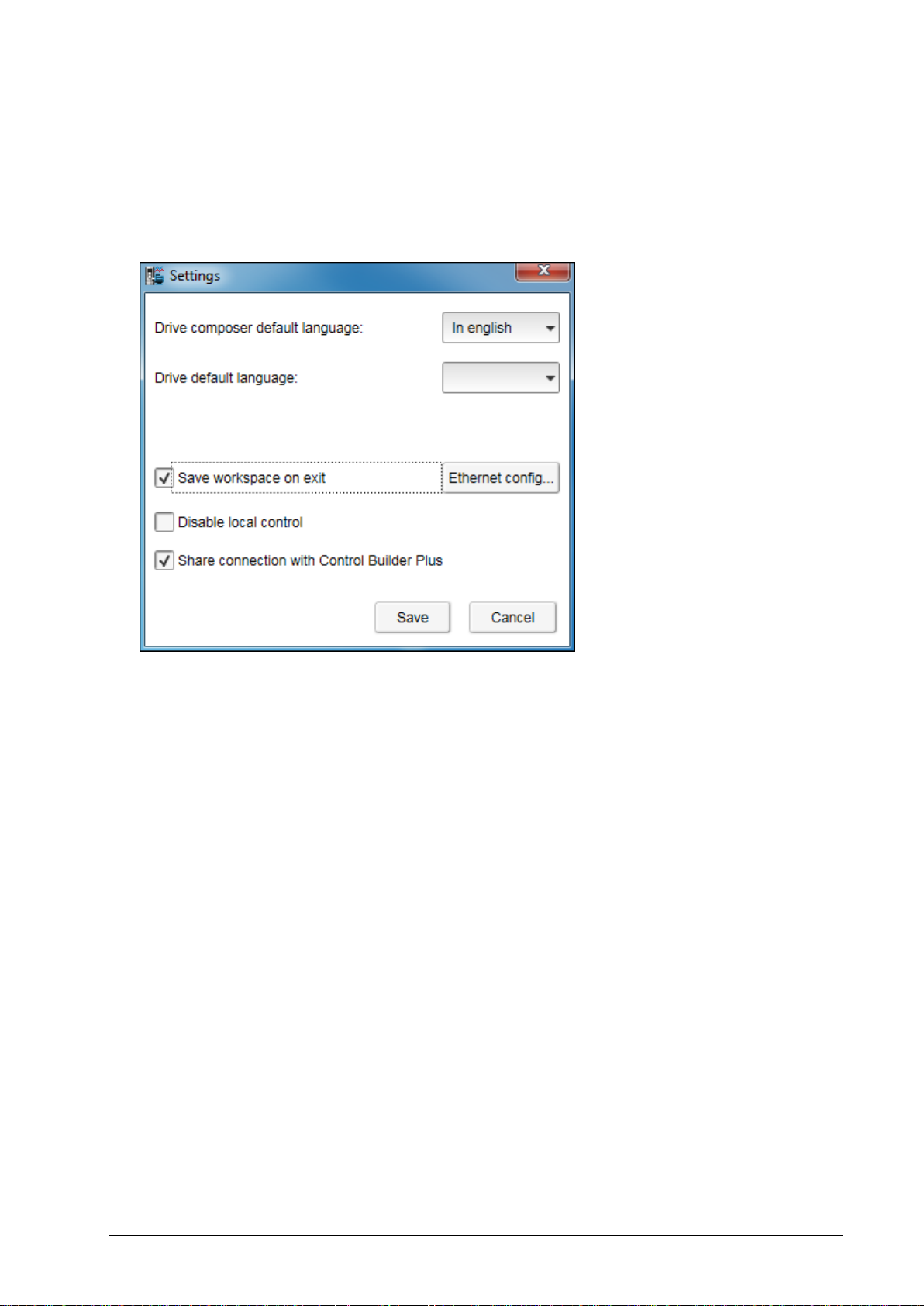
To allow parallel communication with Automation Builder and Drive composer pro, follow these
steps:
1. In the main menu of Drive composer pro, click View and then click Settings.
2. In the Settings window, select Share connection with Control Builder Plus check box and
click Save.
Figure 2: Drive Composer Pro settings
After configuring the settings, restart Drive composer pro.
Drive composer now connects to the drive and allows opening the Automation Builder.
Now you can create an application program. See section, Creating application program.
Page 20

20
Page 21

21
Note: For using ABB Automation Builder online with the drive, enable the drive application
programming license in the target drive. See section, Establishing online connection to the
drive.
3
Overview of drive programming
Contents of this chapter
This chapter provides an overview of ACS880 and DCX880 drive programming environment and a
typical work cycle of drive application programming.
Drive application programming
ABB ACS880 and DCX880 industrial drives can be ordered with the application programming
functionality. It allows you to add your own program code to the drive using the ABB Automation
Builder programming tool (version 1.1). The programming method and languages are based on the
IEC 61131-3 programming standard. ABB Automation Builder is also used for configuring and
programming the ABB AC500 PLC family devices.
With the drive application programming, you can create application specific features on top of the
drive firmware functionality. You can utilize the standard and extension I/O and communication
interfaces of the drive along with the appropriate firmware signals. Your program is executed in
parallel with the drive control tasks using the same hardware resources.
In addition, you can create your own parameters and events (faults and warnings) that are visible on
the ACS-AP-x control panel and in the Drive composer pro/entry commissioning tools.
Page 22
22
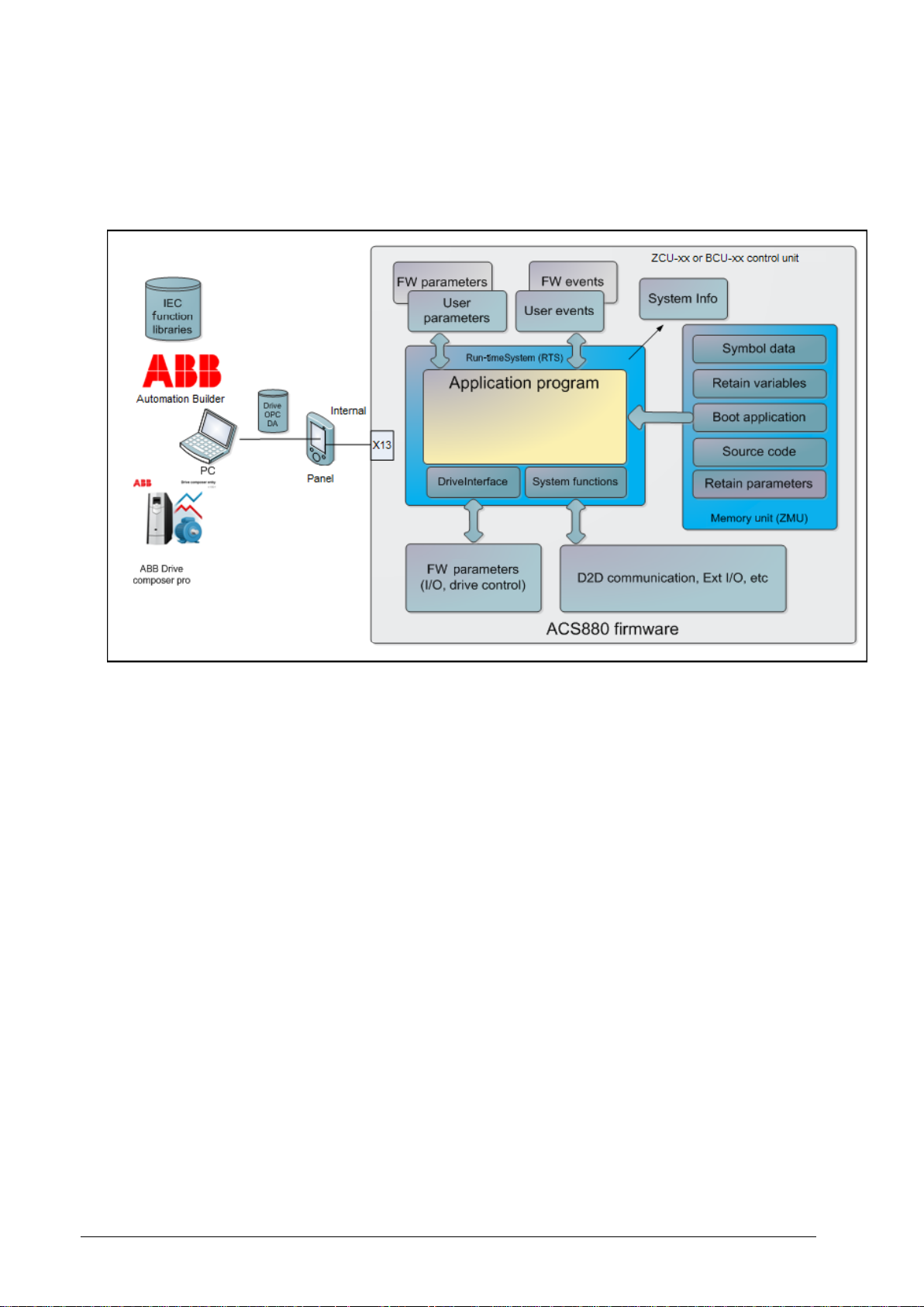
System diagram
The following simplified system diagram shows the application programming environment in the
same control unit as the drive firmware.
Figure 3: Application programming environment – System diagram
The following list describes the main components for application programming.
Drive control unit:
Run-time system (RTS) executes the application program.
DriveInterface allows input/output mapping between the application program and drive
firmware parameters.
System function library enables access to the drive system services (parameters/ events/
drive-to-drive communication, extension I/O).
User made parameters.
User made events (fault, warnings).
Drive System info includes version information of the application program.
Drive firmware parameters with I/O controls.
D2D function blocks enable drive to drive communication, I/O extension modules, and so on
for application programming.
Drive memory unit:
Creates a permanent version of the application program (Boot application).
Retains values of the application program variables .
Consists of application source code (Note that the size of the memory is limited).
Page 23

23
Includes symbol and address information of the application program variables for monitoring
purposes.
PC tool programs:
ABB Automation Builder for application program development and online operations.
ABB Drive composer pro for drive parameter, signal, event log monitoring and settings.
Application program function libraries (for example, ABB standard library).
The USB/ACS-AP-x control panel enables communication between the Automation Builder,
Drive composer pro and the drive.
Programming work cycle
The following steps describes a typical work cycle of the drive application programming tasks of
performing the module:
1. Creating a new project, adding objects, defining the target and first program module in the
Devices tree.
2. Defining the interface to drive firmware parameters (I/O access, drive control) in the
DriveInterface object.
3. Defining user parameters and events (ApplicationParametersandEvents) module in the Devices
tree.
4. Developing the program structure and coding program units.
5. Defining the program execution task configuration editor.
6. Compiling and loading the code using Build menu.
7. Creating boot applications if new parameters, mappings, events or task configuration are added
in the Online menu.
8. Debugging the program code (stepping, forcing variables and breakpoints) in the Online menu.
9. Monitoring program variables in Automation Builder and Drive composer pro from the watch
windows of the View menu.
10. Repeating the cycle from step 2 to 8 for testing the program.
Special tasks
The following special tasks are part of the drive application programming tasks:
1. Saving or restoring the source code to the permanent memory of the drive using the Online
menu.
2. Saving the drive IEC symbol data to permanent memory of the drive from the Devices tree using
the option Add Symbol configuration object to the tree.
3. Naming and versioning the application from the Application properties window or Project
information.
4. Removing the application from the target using Reset origin window on the Online menu.
Page 24

24
Programming languages and modules
The programming environment supports programming languages as specified in the IEC 61131-3
standard with some useful extensions. The following programming languages are supported:
Ladder diagram (LD)
Function block diagram (FBD)
Structured text (ST)
Instruction list (IL)
Sequential function chart (SFC)
Continuous function chart (CFC), normal and page-oriented CFC editor
A program can be composed of multiple modules like functions, function blocks and programs. Each
module can be implemented independently with the above mentioned languages. Each language
has its own dedicated editors. For more information of the programming languages, see
Automation Builder online help and chapter Features.
Libraries
Program modules can be implemented in projects or imported into libraries. A library manager is
used to install and access the libraries.
The two main types of libraries are:
Local libraries (IEC language source code, for example, AS1LB_Standard_ACS880_V3_5)
External libraries (external implementation and source code, for example,
AY1LB_System_ACS880_V3_5)
Local libraries include source code or can be compiled. If the library is compiled, source code is not
included in the library.
External libraries include AC500 PLC libraries used with the drive target by opening the library
project in Windows as Automation Builder project files (before V3.0).
For more information on compatibility, see chapter Libraries.
Program execution
The program is executed on the same central processing unit (CPU) as the other drive control tasks.
In real time applications, programs are typically executed periodically as cyclic tasks. The
programmer can define the cyclic task interval. For more information, see chapter Features.
DriveInterface
The DriveInterface object enables input and output mapping between the application program and
the drive firmware using the drive firmware parameters used in the application program. This list of
parameters may be different for each drive firmware versions. For more details on implementing the
DriveInterface and updating parameter list, see section DriveInterface.
Page 25

25
ApplicationParametersandEvents
The ApplicationParameterandEvents Manager (APEM) object allows creating application parameter
groups, parameters, parameter types, parameter families, units and application events for the drive
in Automation Builder environment. For more details on how to create parameter related tasks and
application events, see section ApplicationParametersandEvents.
Page 26

26
4
Creating application program
Contents of this chapter
This chapter describes the procedure to create application program.
For details of instructions and further development steps see chapters DriveInterface, Application
parameter and event creation, Features and Libraries. For more detailed descriptions, see also the
Automation Builder online help.
Page 27
27
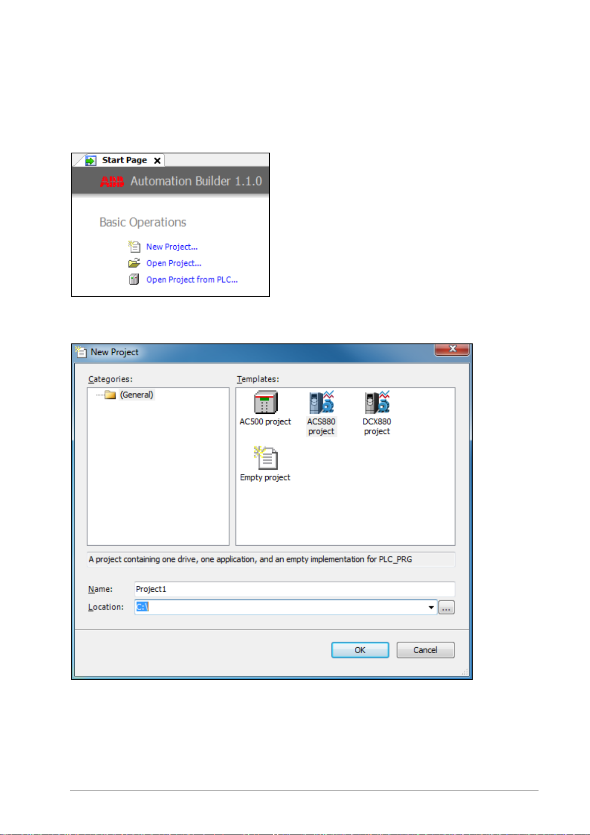
Creating a new project
After starting ABB Automation Builder programming environment, you can create a new project.
1. In the Start Page, click New Project or in the main menu, click File and then click New Project.
Figure 4: Automation Builder – Create a new project
2. In the New Project dialog box, select ACS880 or DCX880 project and click OK.
Figure 5: Select a project
Note: If required, rename the project in Name field and select the desired Location in the file
system.
Page 28
28
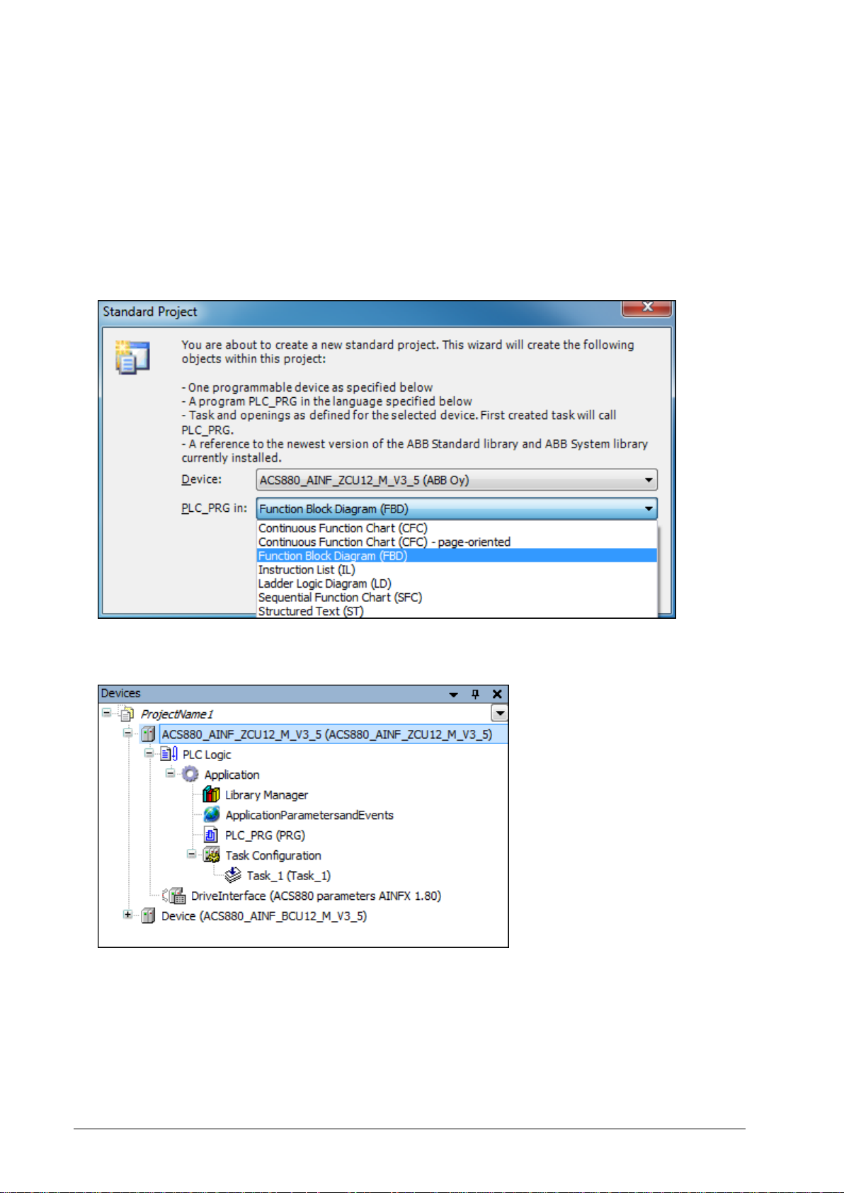
3. In the Standard Project dialog box, select the type of control unit in Device drop-down list.
ACS880_AINF_ZCU12_M_V3_5 for ZCU-xx control unit
ACS880_AINF_BCU12_M_V3_5 for BCU-xx control units
Check the control unit type of the target drive either from the unit itself, from the hardware
manual of drives or contact your local ABB representative.
4. In the PLC_PRG in drop-down list, select a programming language and click OK.
You can later add program modules made with other languages to the project.
Figure 6: Select a programming language
A simple project for an ACS880 target drive is created in the Devices tree.
Figure 7: New project created in the Devices tree
Page 29
29
The Devices tree includes:
PLC Logic
DriveInterface for firmware signal and parameter mapping
Application (for example, you can add the following objects under Application)
o Library Manager for installing function libraries
o ApplicationParametersandEvents for creating user parameters and events
o Program organization units (POUs)
o Task Configuration module for defining in which task the POUs are executed
o Text list
o Symbol configuration
o Global variable list
o Data type units (DUT)
For changing the device type, see section Changing an existing device.
Updating project information
You can update a Company name and Version number for the application program in the Project
Information window. This information is visible in Drive composer tool and ACS-AP-x control panel in
the System info display. It also helps to identify the loaded application without the Automation
Builder tool. You can also name the application from the application tool.
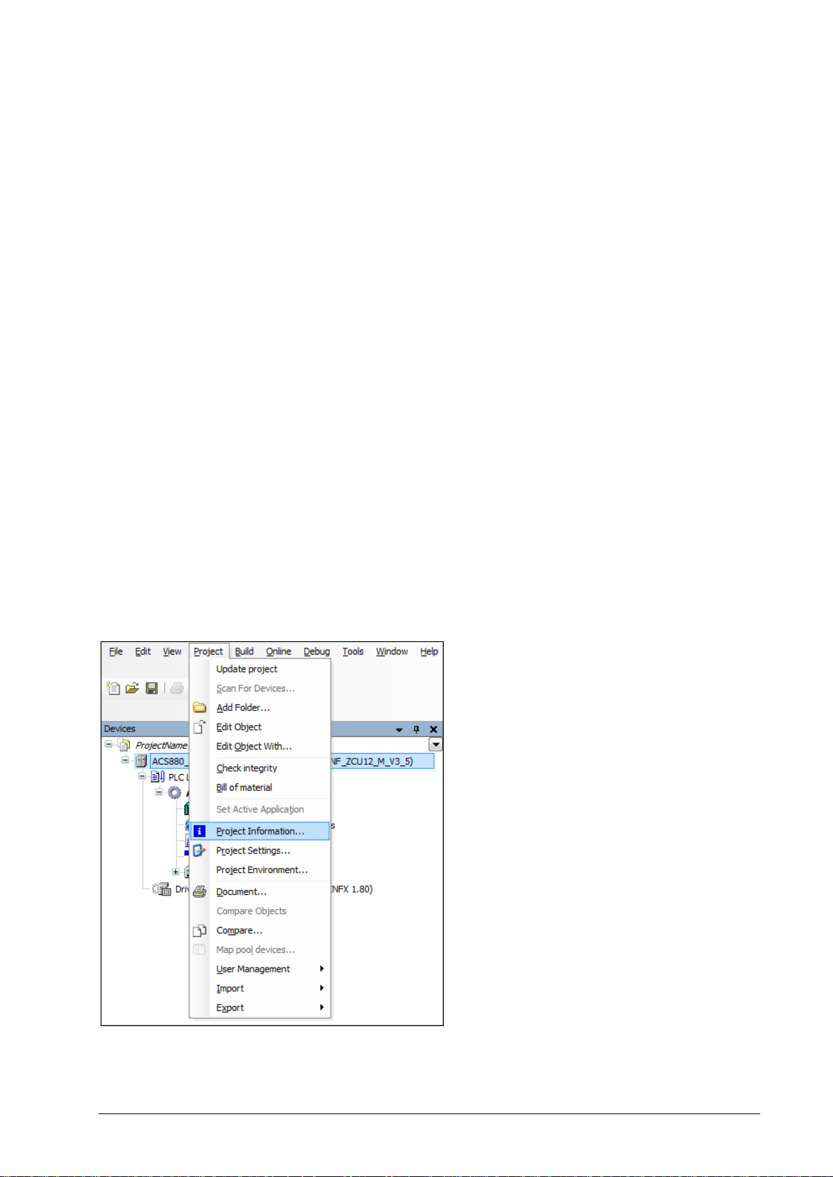
To update project information in Automation Builder, follow these steps:
1. In the main menu, click Project and then click Project Information.
Figure 8 Updating project information
Page 30
30
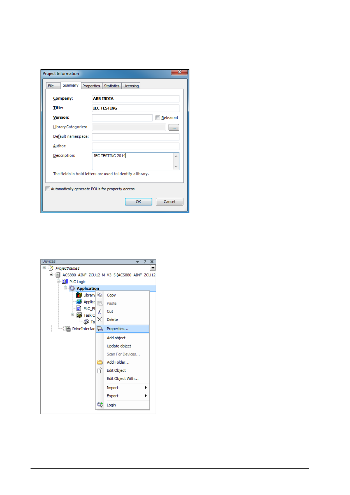
2. In the Project Information window, select Summary tab, update the desired information and click
OK.
Figure 9: Project information
The updated project information is not loaded to the target application. Further steps explain how
to copy this information to the application information fields.
3. In the Devices tree, right click Applications and select Properties.
Figure 10 Application properties
Page 31

31
4. In Properties window, click Information tab and then click Reset to values from project
information and click OK.
Figure 11: Copy information to application information fields
The Automation Builder tool version and project identification code are registered automatically.
Page 32

32
Appending a new POU
To append a new POU, follow these steps:
1. In the Devices tree, right-click Application and select Add object.
Figure 12 Application add object
2. Select POU and click Add object.
Figure 13 Add POU object
Page 33

33
3. In the Add POU window, Name the POU, select the Type of the POU and the used
implementation language and then click Add.
Figure 14: Add POU
The appended POU, xxx (PRG) is added to the Devices tree under application and the POU
window is displayed with the declaration part and the program code.
Figure 15 POU page
Page 34

34
Writing a program code
A program organization unit (POU) is a unit, object or area where you can write the program code.
The units can be created either directly under the Applications in the Devices tree or in a separate
POUs window (View ->POUs or click POUs in the lower left corner).
The POU includes a declaration part (the upper window) and a program code part (the lower
window).
Figure 16: POU window
There are two different types of views for declaration part: a textual view and tabular view . You
can switch between these views by clicking the buttons.
Figure 17 POU view type
Page 35

35
Continuous function chart (CFC) program
This example shows how to create a new project in the CFC implementation language.
Adding elements
1. In the Devices tree, select the xxx (PRG) under the Application.
Figure 18 PLC PRG
2. In the View menu, select ToolBox.
Figure 19 ToolBox
Page 36

36
ToolBox components are displayed and are used to add a CFC scheme.
Figure 20: CFC scheme
If an empty ToolBox list is already displayed on the right side of the window, double-click the xxx
(PRG) to display the Toolbox and the POU window. You can add, for example, SEL and AND
elements (logic operators, functions), use the Box element in the ToolBox list.
3. In the ToolBox list, drag the Box and drop in the program code area.
Figure 21: ToolBox: Box element
Page 37

37
Note: The number in the upper right corner of the white box indicates the execution order
of the function.
4. Enter the name of the function or operand in the ??? field.
You can also use Input Assistant to find the function, keyword, and operator. To start
Input Assistant, click or press F2.
Figure 22: Input assistant
5. Right-click on input or output element and select Negate to invert.
Figure 23: Invert input/ouput
Page 38

38
Setting the execution order of the elements
Each element has its own execution order. The number in the upper right corner of the element
indicates the sequence in which the elements in a CFC network are executed in the online mode.
Processing starts from the element with the lowest number, that is 0. Note that the sequence
influences the result and are changed in certain cases.
To set execution order of the elements, follow these steps:
1. Right-click on element and then click Execution Order and select Set Execution Order.
Figure 24: Execution order
2. In the Set Execution Order window, type New Execution Order number and click OK.
Figure 25 Set execution order
The block execution order is changed.
Page 39

39
Adding comments to a CFC program
In the ToolBox, select Comment and drag to desired point in the program code area and enter the
comment text.
Figure 26: Add comment to a CFC program
Declaring variables
To create a new variable, you can either declare it in the declaration part of the editor window or use
Auto declaration.
Depending on the type of the declaration view (textual or tabular) add a new variable by writing its
properties to a new text row (textual view) or use the TAB button (tabular view). For changing
between the views, see section Writing a program code.
1. In the program code area, select the required object.
2. In the main menu, click Edit and then click Browse and select Auto Declare.
Figure 27 Auto declare option
Page 40

40
The Auto Declare window is displayed.
Figure 28 Auto declare variables
If you enable the option to declare unknown variables automatically (Tools -> Options ->
SmartCoding), the Auto Declare window opens every time you use an unknown variable in your
program and you can declare the variable instantly.
3. Define the Scope, Name and Type of the variable (mandatory).
Scope defines the type of variable (global, input, output, etc.).
Name is a unique identifier of the variable and represents the purpose of the variable.
Type is the IEC data type of the variable.
Optionally, you can also define the Initialization value, Address, Comment or Flags for the
variable.
Flags have the following meaning:
CONSTANT means that the variable value cannot be changed and the variable maintains
its initial value all the time.
RETAIN keeps its value over reboot and warm reset.
PERSISTENT is not supported.
Page 41

41
Adding inputs and outputs
You can add inputs and outputs by selecting ToolBox elements. See section Adding elements.
Figure 29: ToolBox for adding inputs and outputs
Another way to add inputs and outputs straight to a block is to select a pin of a block and start typing
the name of a variable.
1. In the program code area, select the pin of the block.
Figure 30 Naming inputs and outputs
2. Name the input or output by writing the variable name to the block or use input assistant as
described in Declaring variables.
3. To connect the input or output block to a pin, left-click the line connected to the block and drag it
to a pin of another block.
Page 42

42
Creating a block scheme
Example:
Create the following CFC program:
Figure 31: Example of CFC program
The following local variables are required in the block scheme.
Figure 32 Local variables
During block scheme programming, the already created variables are displayed in the Input
Assistant and new declarations are added to the variable declaration area.
For using the Input Assistant, see section Adding elements in Continuous function chart (CFC)
program.
Page 43

43
Preparing a project for download
To prepare a project for download, follow these steps:
1. In the main menu, click Build and select Build.
Figure 33 Build
2. In the View menu, select Messages. A Messages window is displayed.
Check that there are no errors or warnings. Otherwise, check and fix the application.
Figure 34: Build project message window
In the example, the process is successfully completed without any errors or warnings and the
project is ready for download.
Establishing online connection to the drive
The Automation Builder communication gateway handles communication between Automation
Builder and the drive. The gateway is a software component that starts automatically at the powerup of the PC after installing Automation Builder.
Before starting with the communication setup, follow the pre-requisites listed below.
Pre-requisites:
Page 44

44
1. Connect PC to a drive through USB port of the ACS-AP-x control panel using a standard USB
data cable (USB Type A <-> USB Type Mini-B). For information on making the control panel to
PC USB connection, see ACS-AP-x control panel user’s manual (3AUA0000085685 [English]).
2. Make sure the ACS-AP-x USB driver is installed. For installation procedure, refer Drive
composer user’s manual (3AUA0000094606 [English]).
3. Make sure the drive has application programming license N8010. To check license information in
Drive composer pro and in ACS-AP-x control panel, go to System info -> Licenses.
To establish online connection to the target drive after defining the device type, follow these steps:
1. In the Devices tree, double-click ACS880_AINF_ZCU12_M_V3_5 and then click
Communication Settings.
Gateway-1 is displayed by default.
Figure 35: Communication settings
Page 45

45
Note: If the gateway displays red , the CODESYS Gateway V3 is disabled in local
control panel settings.
Figure 36 Gateway disabled
2. Open Control panel -> Administrative Tools -> Services in the user PC.
3. In the Services window, double-click CODESYS Gateway V3.
Figure 37 Gateway services
A Properties window is displayed.
Page 46

46
4. In the Properties window, select the desired Startup type from the available drop-down list and
click OK.
Figure 38 Startup type
CODESYS Gateway V3 is enabled and turned to green .
Figure 39 Gateway enabled
Page 47

47
5. Ensure that the following default communication settings are correct.
Node Name: Gateway-1
Driver: TCP/IP
IP- Address: localhost (Remote gateways are not scanned)
Port: 1217
6. If Gateway-1 is not available, click Add gateway.
Figure 40 Add new gateway
7. In the Gateway window, select the appropriate settings and click OK.
Figure 41 Gateway settings
Page 48

48
8. Check that the USB cable is connected to the USB connector of the ACS-AP-x control panel and
the drive is powered.
For communication related problems, see practical examples and tips for Solving communication
problems.
9. Double-click Gateway-1 or click Scan network to search the target device.
Filter Target ID displays only devices that are of the same type as the device selected in
the Devices window.
The gateway device is added under Gateway-1.
Figure 42: Adding devices under Gateway
10. Under Gateway-1, double-click or right-click the device and select Set active path.
Figure 43: Activating devices under gateway
If the drive has appropriate license code, the selected device is set as active path and is
ready for downloading a program to the drive. See section Downloading the program to the
drive.
Page 49

49
Note: To see which port and node is used by each device, see the information in the
device name in brackets [GGGG.PPNN] where:
GGGG is the gateway number
PP is the OPC channel number
NN is the OPC node number
If the drive does not have the required license code, the selected device is displayed with no
license.
Figure 44: No license notification
Page 50

50
Downloading the program to the drive
After the project is ready for online communication with the drive, you can download and execute the
written program to the drive. Check that the active path to the target device is defined in the
communication settings. For more information, see section Establishing online connection to the
drive.
1. In the main menu, click Online and select Login.
Figure 45 Login
The following dialog is displayed if the program is not downloaded before. Click Yes.
Figure 46: Perform a download
Page 51

51
After the download is complete, the background color of the device name and the application
name in the Devices tree changes. The program is in stop mode and the status is shown in the
brackets [stop]. You can start the program by selecting Start in the Debug menu.
Figure 47 Program in stop mode
For more information on downloading program, see section Application download options in
chapter Features.
Page 52

52
Executing the program
To execute a program, follow these steps:
1. In the main menu, click Debug and select Start.
Figure 48: Debug menu
The application status changes to [run] and notifies that the program is executed successfully.
Figure 49 Executing a program
2. To set or change a value of an existing variable, double-click the cell in the Prepared value
column, type a new value and press Enter.
3. In the Debug menu select Write values to apply the prepared value to the variable.
4. In the Debug menu, select Force values to force the prepared value to the variable.
5. In the Debug menu, select Unforce values to unforce a forced value.
The variable value is changed. The current variable values are displayed in the Value column
and in the source code near the variable.
Page 53

53
WARNING! Ignoring the following instruction can cause physical injury or damage to
the equipment.
Do not debug or make changes to drive in the online mode or while the drive is
running to avoid damage to the drive.
6. In the Debug menu, click Stop and then in the Online menu, click Logout to logout.
Page 54

54
Creating a boot project
The regular downloading moves the application program to the RAM memory of the drive. Creating a
boot project copies the application to the non-volatile memory of the drive memory card and thus
retains the application after power cycle or reboot. For more details, see section Application
download options.
To create a boot project, follow these steps:
1. In the main menu, click Online and select Create boot application.
Figure 50: Create boot application
The following message is displayed. Click Yes to reboot the drive.
Figure 51: Reboot drive after boot project
The reset to default values is optional. If you select Reset application parameters to defaults
option, the next boot resets all the application parameters to their default values. The previously
set values are not restored from the permanent memory.
Page 55

55
Note: It is recommended to select the Reset application parameters to defaults
option whenever you load a new application to the drive or whenever you change
the parameter definitions of the existing application (APEM).
Select this option when a new application is loaded to drive or a reset origin has been performed
or when application parameters of the new application are different from the previously loaded
application.
After creating the boot application, the status changes from STOP to RUN.
2. System prompts to save the boot application, click Save.
Page 56

56
5
Features
Contents of this chapter
This chapter describes the device handling information and features supported by Automation
Builder.
Device handling
In the application programming environment, devices represent hardware. The device description file
contains information about the target device (drive) from the programming point of view like the
device identifier, compiler type and memory size. The ABB Automation Builder installation package
installs the device description files automatically.
The device description may be updated later and a new file can be installed. The system monitors
that a project with an incompatible device description file is not loaded to the drive.
The following topics describe device handling:
Viewing device information
Upgrading or adding a new device
Changing an existing device
Viewing software updates
Page 57

57
Viewing device information
To view the detailed device information, follow these steps:
In Devices tree, double-click device and click Information tab.
Figure 52: Device information
The Device ID (1612 0010), Drive FW name (AINFX) and application interface version (3.0.0.1) must
be identical in the project and drive target. In Drive composer pro, use the System info option to
check that the drive target has the corresponding application interface version and device type and
drive firmware name (displayed in parameter 7.04).
Page 58

58
You can also check if the drive target has the corresponding application interface version and device
ID.
In Drive composer pro, click System info -> Products -> More.
Figure 53: Checking drive compatible application and device
The name and version of the available system library is displayed. Make sure this information
matches with the installed system library of the Automation Builder project.
For more information, see parameter 7.23 for Application name and parameter 7.24 for version in
ACS880 FW.
For details of available functions, see chapter Libraries.
Page 59

59
Upgrading or adding a new device
You can upgrade or add a new device to the programming environment.
1. In the main menu of Automation Builder, click Tools and select Device Repository.
Figure 54 Automation Builder device repository
Device repository window is displayed.
2. Click Install to select device description file.
Figure 55: Device Repository window
Page 60

60
3. In the Install Device Description window, browse and select the device description file
(.devdesc.xml) in the file system.
Now you can add a new device to projects or upgrade currently existing devices in the project.
Changing an existing device
You can change an existing device in Automation Builder project.
1. In the Devices tree, right-click on Device and select Update object or in the main menu, click
Project and select Update project.
Figure 56: Update an object
The Update object window displays the available device types.
2. Select the required drive device and click Update object.
Page 61

61
Figure 57 Update object device
Viewing software updates
In the Automation Builder start page, click Automation Builder to download Automation Builder
update packages.
Figure 58: Automation Builder start page
Page 62

62
This link is the download center for low voltage products and systems (India). For example, you
can find Automation Builder Service Release 1 – Release note, Automation Builder update
packages, and so on.
Page 63

63
Program organization units (POU)
The POU types are:
A program (PRG) may have one or several inputs/outputs. A program may be called by another
POU but cannot be called in a function (FUN). It is not possible to create program instances.
A function (FUN) has always a return value and may have one or several inputs/outputs. The
functions contain no internal state information.
A function block (FB) has no return value but may have one or several outputs as declared in the
variable declaration area. A function block is always called using its instance and the instance
must be declared in a local or global scope.
A created project may have POUs with a specified implementation language. Each added POU
has its own implementation language.
For more detailed description of the POU types, see the IEC programming environment user manual
and the IEC 61131-3 open international standard.
Page 64

64
Data type
Size
(bits)
Range
Supported
by BCU-xx
Supported
by ZCU-xx
Notes
BOOL
8/16*
0, 1 (FALSE, TRUE)
Yes
Yes
8 bit BCU-xx
16 bit ZCU-xx
SINT
8
-128...127
Yes
No
INT
16
-215...215-1
Yes
Yes
DINT
32
-231...231-1
Yes
Yes
LINT
64
-263...263-1
No
Yes
USINT
8
0...255
Yes
No
UINT
16
0...65535
Yes
Yes
UDINT
32
0...2
32
Yes
Yes
ULINT
64
0...2
64
No
Yes
BYTE
8
0…255
Yes
No
WORD
16
0...65535
Yes
Yes
DWORD
32
0...232-1
Yes
Yes
LWORD
64
0...264-1
No
Yes
REAL
32
-1.2*10
-38
...3.4*1038
Yes
Yes
LREAL
64
-2.3*10
-308
...1.7*10
308
Yes
Yes
Slow. Do not use.
TIME
32
0 ms... 1193h2m47s295ms
Yes
Yes
LTIME
64
0 ns...~213503d
Yes
Yes
TOD
32
00:00:00...23:59:59
Yes
Yes
DATE
32
01.01.1970...~06.02.2106
Yes
Yes
DT
64
01.01.1970 00:00...
~06.02.2106 00:00
Yes
Yes
STRING[xx]
0...255 characters
Yes
No WSTRING[xx]
0...32767 characters
Yes
Yes
Data types
The ABB drives application programming does not support some of the standard IEC data types like
BYTE, SINT, USINT and STRING. The following list gives the standard IEC data types, sizes and
ranges.
Drive application programming license
The drive application programming license N8010 is required for downloading and executing the
program code on the ACS880 or DCX880 drives. To check license information in Drive composer
pro or in ACS-AP-x control panel, go to System info -> Licenses. If the required license code is not
available, contact your local ABB representative.
Page 65

65
Note: It is not recommended to download a program to the RAM memory when the drive
is in RUN mode. The drive must be in STOP mode and Start inhibits must be possible to
set.
Note:
Firmware parameter mapping, task configuration, application parameters
and event configuration are activated only after the boot application is
loaded and the drive is booted.
Start inhibition is not granted if the drive is running, disabled (DIL, Safety
function active) or faulted. Make sure that these conditions do not exist
before downloading the program.
Application download options
Before executing an application in the drive, download the application to the drive memory. After
downloading, the application software is embedded in the firmware of the drive and has access to
system resources.
Before download, ensure that there is no fieldbus device, M/F-link or D2D-link connected to the drive
and Drive composer is not running data monitoring or back-up/restore at same time.
There are two different download options:
Download – This is a regular download method that copies the compiled application to the
drive RAM memory. As a result, it is possible to execute the application, but after a power
cycle or reboot the memory is erased. This download method does not alter an application
that is located in the drive boot memory (ZMU) and the original application is available for
use after a reboot.
Create boot application – This download method copies the application to the non-volatile
memory of the drive memory card. This way the application remains intact after a power
cycle or reboot. You should be logged into the drive to perform this operation. Features that
can work only after restarting the drive should be downloaded with this method.
Create boot application command (Online -> Create boot application) also includes booting
the drive. Rebooting stops the execution of the complete drive firmware for some time. For
this reason, it is allowed only when the drive is stopped and start inhibition is granted to the
Automation Builder.
Page 66

66
Removing the application from the target
Use the Reset option if the application includes many changes like application parameter changes or
the application is replaced by another application. If the target already includes an application, use
the Reset origin selection in the Online tab before downloading a new application.
This command removes (clears all) old applications from the target and all the application related
references. Use this command at least once before the final version of application is loaded. The
command can be used only in the online mode. See also Reset options.
When you are prompted with the following message, click Yes.
Figure 59: Initiate reset origin
After you initiate the Reset origin option, the following message is displayed. Click Yes. The
command is executed only if Automation Builder receives the permission from the drive.
Figure 60: Confirm reset origin
Page 67

67
WARNING! In a function block, do not declare a local variable as RETAIN because the
complete instance of the function block is saved in the retain memory area and this large
function block instance may lead to running out of memory space.
Note: Declaring a local variable in a function as RETAIN has no effect and the variable
is not saved in the retain memory area.
The existing retain variables cannot be linked to application parameters.
Task
Time interval
Task_1
1 … 100 ms
Task_2
10 … 100 ms
Task_3
100 … 1000 ms
Note: The application program consists of its own quota of CPU resources. If the limit
exceeds, the drive tips to task overflow fault. For details, see ACS880 Firmware
manual.
Retain variables
Retain variables includes the RETAIN flag used to retain values throughout the drive reboot and
warm reset. A cold reset sets the retain variable to its initial value. The values of retain variables are
cyclically stored in the flash memory of the drive and restored to the stored value after the restart of
the program. The retain variables are stored in a separate 256-byte memory area which defines the
limits of their amount.
In firmware version 1.7 and later, the power control board works with the parameter settings:
If parameter 95.04 = Internal 24V, retain values are saved immediately at the time the drive
loses power, meaning it is not cyclical.
If parameter 95.04 = External 24V, retain values are saved at periodic intervals of 3 minutes.
So the recovered variable may not be the recent value.
Task configuration
The task configuration object handles call configuration of programs. A task is a project unit that
defines which program is called in the project and when it is called. The project can have more than
one task with different time levels.
There are two types of tasks:
Cyclic task (Task_1, Task_2 and Task_3) – These tasks are processed cyclically according
to the task cycle time interval. The following table lists the time intervals available for cyclic
application programs. The highest priority is given to the task with the shortest execution
interval.
Pre_task – This task is executed only once at start-up of the application program. This
feature is useful for one time initialization. POUs (blocks) assigned into this task are executed
before the start of cyclic tasks.
Page 68

68
Adding tasks
To add tasks to Task Configuration, follow these steps:
1. In the Devices tree, right-click Task Configuration and select Add Object.
Figure 61 Task configuration
2. Select Task and click Add object.
Figure 62 Task
Page 69

69
3. In the Task drop-down list, select a task and click Add.
Figure 63: Add tasks
The selected tasks are added in the Task Configuration object.
Figure 64: Tasks added
4. Click Add POU in the newly added Task_2 screen.
Page 70

70
5. In the Input Assistant window, click Categories and then select PLC_PRG and click OK.
Figure 65 Add POU input assistant
6. PLC_PRG is added to Task_2. Drag PLC_PRG to Task Configuration object.
Figure 66 New PLC PRG
Page 71

71
Monitoring tasks
Before adding the tasks for monitoring in Automation Builder, check parameter 7.21 Application
environment status in Drive composer pro.
Figure 67: Drive composer pro, parameter 7.21
The parameter bits 7.21.0, 7.21.1, 7.21.2, and 7.21.3 are used to monitor the application task related
execution. To check the continuous execution of tasks, write the specific task bit to 0. The executing
task bits are updated to 1, except the Pre task, which executes only once.
The calculation of tasks execution cycle (duration) is disabled by default. To view the tasks
execution monitoring in Automation Builder, change Bit 15 = Task monitoring to high.
Page 72

72
Note: The values in the task monitoring view are updated only setting the parameter
7.21.15 to high in Drive composer pro. This setting is configured again after the power
cycle or boot or control board.
To add task monitoring view in Automation Builder, follow these steps:
1. In the Devices tree, double click Task Configuration.
2. Click Monitor tab to check the status report of available tasks.
The status report of available tasks appears.
Figure 68: Task monitoring view
Page 73

73
Uploading and downloading source code
Optionally, the source code of the project can be saved in the drive. This feature is located in
Automation Builder main menu Online -> Source download to connected device and it ensures
that the files are easy to obtain if needed.
To retrieve the saved source code from the drive to a new project, follow these steps:
1. In the Devices tree, right-click Device and select Source upload.
Figure 69 Source upload
2. Select the drive and click OK.
Figure 70 Source upload device
Page 74

74
Note: If the source code is saved on the ZMU memory unit, you can retrieve the program
with another PC without the authors consent unless the project is password protected.
The size of the source code is limited to 500 KB. Check the archiving option to minimize the source
code size (File -> Project Archive -> Save/Send Archive…). Note that referenced devices and
libraries are needed, the rest is optional.
Page 75

75
Adding symbol configuration
To add symbol configuration in Automation Builder project, follow these steps:
1. In the Devices tree, right-click Application and select Add object.
Figure 71 Add object for symbol configuration
2. Select Symbol configuration and click Add object.
Figure 72 Symbol configuration
Page 76

76
3. In the Add Symbol configuration window, click Add.
Figure 73 Add symbol configuration
Symbol configuration object is added to the project.
Figure 74 Symbol configuration object
Page 77

77
Note: Online changes of the program code are not supported.
WARNING! Ignoring the following instruction can cause physical injury or damage to
the equipment.
Do not set breakpoints and force variables on a running drive that is connected to
motor.
After adding Symbol configuration object to the project, the IEC variable to symbol data is loaded
into the drive during the create boot application download. See section Application download
options. This feature provides Drive composer pro access to the application variables which is used
for graphical monitoring and debugging.
For more information on the Symbol configuration editor and adding variables, see Automation
Builder Online help.
Debugging and online changes
The following debugging features and variable forcing are supported:
Start / stop program execution
Setting breakpoints
Stepping code line by line or by function
Forcing variables (constant setting of variable values)
Writing variables (single setting of variable values)
Safe debugging
When debugging the application program of a running drive connected to motor in the online mode,
avoid the following actions:
stopping the application program
setting breakpoints to the application program
forcing variable values
assigning values to outputs
changing the values of a local variable in function blocks
assigning invalid input values
Breakpoints stop the entire application, instead of just the task that has the currently active
breakpoint.
Page 78

78
Note: The reset origin action cannot be undone. However, the parameter values of the
old application are not removed. These values can be removed only when creating the
next boot application by selecting the Reset application parameters to defaults
option. See section Creating a boot project.
If the application is stopped, press F5 to restart the application.
Reset options
You can reset the application, using the reset selections in the Online mode.
1. In the Devices tree, select the Application.
2. In the main menu, click Online and select the desired reset method.
Figure 75 Reset options
Reset warm resets all variables of the currently active application to their initial values
(except retain and persistent variables). In case of specific initial values, the variables are
reset exactly to those specific values.
Reset cold resets all variables (normal and retain) of the currently active application to their
initial values.
Reset origin erases the application, downloaded to the drive from the RAM and the memory
unit (Boot application). In case of specific initial values, variables are reset to those specific
values. Drive firmware parameter mappings, user-defined parameters and events are also
removed. Finally the drive is restarted.
Page 79

79
Note: To optimize the memory consumption, avoid using function blocks and
unnecessary variable definitions.
Memory limits
To see the effective size of the program, follow these steps:
In the main menu, click Build and select Clean or Clean All to remove temporary code sections
from the program.
Figure 76 Build clean
The build report shows the actual memory allocation.
Memory area 0 is assigned for code and data. Memory area 1 is assigned for retain variables.
See the example screen below.
Figure 77: Memory limits – example
Page 80

80
CPU limitation
The maximum execution load of the application is limited to a certain value of 5 to 15% depending
on the drive type. To know the actual load limit, contact your local ABB representative.
Use parameter 7.11 to check the application load which monitors the CPU load. To know the load
difference, compare the values between with and without the application. Ensure that the difference
value is not greater than the value limit. If the application exceeds the limit, the drive trips to the task
overload fault 6481. The fault is registered to the event log of the drive and the fault-specific AUX
code indicates the overloaded tasks (10 = task 1, 11 = task 2 and 12= task 3).
Perform CPU load tests to ensure that the drive is capable of adequately running the application.
Enable the required drive functions during the execution of the application. For example, motor
control, communication modules, encoders, and so on.
Page 81

81
Application loading package
This feature allows the user to create loading package containing an application program for
ACS880 drive. Loading package file is built with Automation Builder command Create Boot
Application in case the tool is in online connection to the drive.
Loading package file must be placed to the corresponding project folder with the file name
<project_name>_<device>_<application>.lp. The user can load application loading package using
Drive loader 2.1 tool. Application loading package functionality supports from AINFX 2.01 firmware
version onwards.
Before loading the package, Drive loader tool checks for the correct actual drive type and firmware
version to load the package. It also checks for the correct drive application programming interface
and programming license (N8010) is active in target drive.
To include symbol data and source code to application wrap file and loading package using
Automation Builder, follow these steps:
1. In the main menu of Automation Builder, click Project and then select Project Settings.
Figure 78 Project settings
Project settings window is displayed.
Page 82

82
Note: Ensure that the application is working correctly with the added firmwares.
2. In the Project Settings window, click Application loading settings and select the desired
check boxes.
Figure 79 Application loading settings
It is also possible to add more supported firmware versions to the application loading
package.
3. Click to add new firmware.
4. Enter the firmware details and click Ok.
Figure 80 Adding supported firmwares
The added firmware is displayed in the Application loading settings.
Page 83

83
Downloading loading package to a drive
Drive loader tool is used to download loading package to common platform drives.
1. Start Drive loader tool.
2. Click Open to download a loading package or click Scan to scan for a connected device.
Figure 81 Drive loader tool
Page 84

84
3. Select the desired loading package file (.lp) and click Open.
Figure 82 Loading package
4. Select the desired drive and click Select.
Figure 83 Drive selection
Page 85

85
Note: Before starting downloading, ensure Automation Builder and Drive composer are
not running at the same time.
5. In the Software Set drop-down list, select the appropriate selection.
1: Loads new application, set application parameters to default and removes user sets
from the drive.
2: Loads new application.
3: Removes the application from the drive (reset origin). Before using this option, the user
must first load application loading package using options 1 or 2.
4: Removes user sets from the drive.
Figure 84 Software set
6. Select the desired communication Serial port and click Download.
Before starting downloading, drive loader checks for the following:
Correct control board (ZCU/BCU).
Same device ID in Automation Builder project and drive control board.
Correct version of application environment.
Programming license loaded to target (N8010).
FW version supported in loading package.
Page 86

86
A warning message is displayed. Click OK.
Figure 85 Warning message
7. In case of restrictions due to incompatible firmware version, the Drive loader stops and
displays an error message.
Figure 86 Error message
8. Click downloading.txt to view error log file.
Page 87

87
6
DriveInterface
Contents of this chapter
This chapter describes how to implement DriveInterface and map input/output settings between the
application programs and drive firmware parameters.
Implementing DriveInterface
The interface between the drive firmware and application is implemented using DriveInterface.
Figure 87: DriveInterface
Page 88

88
Note:
The parameter to IEC variable mappings is valid only after creating a boot application.
For more details, see section Application download options.
Drive interface is not completely covering all drive parameters. If the firmware
parameter is not available in the drive interface list, use the AY1LB library functions to
read/write firmware parameters.
In order to fully remove drive parameter settings from drive, use Reset origin option.
Also, re-save user sets (see parameter 96.08) after removing or replacing the
application. As user set may have incorrect mapping of firmware parameter to nonexisting application.
DriveInterface consists of all drive firmware parameters list that can be used in the application
program. This list is specific for each drive firmware (a new firmware may have new parameters).
You can assign a parameter to be an input for the application program and define that the parameter
is read at the beginning of the task execution. Similarly, user can assign parameters to be an output
of the application.
Figure 88: DriveInterface – Assigning parameters for outputs in the application
Page 89

89
Selecting the parameter set
A drive can have different parameters depending on the firmware version. Before performing
parameter modification, ensure that the correct parameter set is selected in DriveInterface. The
changes to parameter set in DriveInterface removes all parameter mapping data.
To change the currently selected parameter set, follow these steps:
1. In the Devices tree, right-click DriveInterface and select Update object.
Figure 89 DriveInterface update object
2. In the Update object window, select the correct parameter set for the current target and click
Update object.
Figure 90 DriveInterface parameter set
Page 90

90
Viewing parameter mapping report
When you download the application program, a report of unresolved parameter mappings between
the project parameters and actual parameters in the drive is written in the PLC log.
Figure 91: Parameter mapping report
For more details on downloading, see sections Downloading the program to the drive and
Application download options.
Page 91

91
Mapping example
To read digital input DI1 of the ACS880 control unit to the previous CFC example (Creating a block
scheme), open group 10 and select index 1.
1. In the Devices tree, double-click DriveInterface.
Figure 92: Parameter mapping window
2. In the Driveinterface window, right-click on the required Assignment cell and select Input or you
can also select the desired Assignment from the available drop-down list.
Figure 93: Selecting input for parameter mapping
Page 92

92
3. Double-click default IEC variable name Device_DI1_10_1. A button is displayed to the right of
the selected name to change the name.
Figure 94: Default IEC variable name
4. Click to change the name. Input Assistant window is displayed.
5. Click Categories and then expand DriveInterface tree to select the Device and click OK.
Figure 95: DriveInterface Input assistant
Page 93

93
Note: If you want to select existing variable DI1 from the POU variable list, expand
Application and under POU, select DI1. DI1 is connected to drive parameter 10.1. DI
status bit 0.
Note: Bit and value pointer parameters can be used as outputs and then the pointer is
linked directly to the application memory.
IEC variable name is changed.
Figure 96 DriveInterface variable name
Figure 97 Existing variable
The mapped parameters are available as IEC variables in the program editors (press F2).
Page 94

94
Updating drive parameters from installed device
You can update the parameter list from the installed device or you can take the actual drive
parameter set used in DriveInterface from Drive composer pro. See section Updating drive
parameters from parameters file.
To update the parameters from the installed device, follow these steps:
1. In the Devices tree, right click DriveInterface and select Update Drive Parameter Set.
Figure 98: Update drive parameter set
Page 95

95
2. In From installed device option, expand Miscellaneous and select the device and then click
Update.
Figure 99: Update parameter from installed device
The parameter list from the selected device is displayed.
Page 96

96
Updating drive parameters from parameters file
Optionally, you can update the actual drive parameter set using the Drive composer pro backup file.
To update the parameters backup file, follow these steps:
1. In the Devices tree, right click DriveInterface and select Update Drive Parameter Set.
Figure 100 Update drive parameter set
Page 97

97
2. In the Update parameter set window, select From parameter file option and browse to select
dcparams (.xml) backup file and then click Update.
Figure 101: Select parameter file
The changes/deleted parameters are displayed. Click OK.
Page 98

98
Setting parameter view
In Automation Builder, you can select the required parameter details to view in the ACS-AP-x control
panel and the Drive composer pro display:
1. In the Devices tree, double-click DriveInterface.
Figure 102 DriveInterface parameter view
2. In the upper-left corner of the DriveInterface window, select Settings.
Figure 103: DriveInterface settings
Page 99

99
3. Select the required view option for the corresponding parameter and click OK.
Figure 104: Hide options
The selected options in the view list are displayed in the DriveInterface parameter window.
Page 100

100
7
Application parameter and events
Contents of this chapter
This chapter describes how to use the Parameter Manager and provides detailed information on
parameter settings.
 Loading...