

ABB i-bus SA/S 2.16.2.1, i-bus SA/S 4.6.1.1, i-bus SA/S 2.16.6.1, i-bus SA/S 2.10.2.1, i-bus SA/S 4.10.2.1 Product Manual
...Page 1

ABB i-bus® KNX
SA/S Switch Actuators
Product Manual
Page 2

ABB i-bus KNX
General
SA/S | 2CDC 505 056 D0208 5
1 General
KNX systems provide an attractive solution that meets the most demanding residential, commercial and
public buildings requirements. H igh liv ing stan dard s, com fort and safety can be easi ly comb ined w ith cos teffectiveness and environmental awareness using KNX bus systems from ABB. KNX products cover the
entire range of buildings applications, from illumination and blind control to heating, ventilation, energy
management, security and surveillance. These requireme nts can be met cos t-effectively with minimal
planning and installation effort using the ABB KNX. Furthermore, flexible room usage and continuous
adaptation to changing requirements are simple to implement. SA/S Switch Actuators fulfill individual
requirements in industrial, commercial and public buildings as well as in the private sector for controlling
switchable loads, e.g.:
• Illumination
• Heating control
• Signaling equipment
Certain types of Switch Actuator can also detect and monitor load current via a threshold value function.
Based on the load current detected, responses can be triggered via KNX and the load can be switched off
directly or switched via KNX.
1.1 Using the product manual
This manual provides you with detailed technical information on the ABB i-bus® SA/S Switch Actuator
range, its installation and programming.
Application of the device is explained using examples.
This manual is subdivided into the following sections:
Section 1 General
Section 2 Device technology
Section 3 Commissioning
Section 4 Planning and application
Section A Appendix
Page 3

ABB i-bus KNX
General
6 2CDC 505 056 D0208 | SA/S
1.1.1 Structure of the product manual
All parameters are described in section 3.
Please note
This product manual describes all the current 2/4/8 and 12-fold Switch Actuators. However, as the
functions for all outputs are identical, only the functions of output A will be described.
Where information in the product manual refers to all outputs, the description output A...X is used. 2-fold
corresponds to outputs A...B, 4-fold corresponds to outputs A...D, 8-fold corresponds to outputs A...H
and 12-fold corresponds to outputs A...L.
Variants with current detection feature an additional parameter page as well as additional
communication objects for this function.
1.1.2 Notes
Notes and safety instructions are represented as follows in this product manual:
Please note
Tips for usage and operation
Example
Application examples, installation examples, programming examples
Important
These safety instructions are used as soon as there is danger of a malfunction without risk of damage
or injury.
Caution
These safety instructions are used if there is a danger of damage with inappropriate use.
Danger
These safety instructions are used if there is a danger to life and limb with inappropriate use.
Danger
These safety instructions are used if there is an extreme danger to life with inappropriate use.
Page 4

ABB i-bus KNX
General
SA/S | 2CDC 505 056 D0208 7
1.2 Product and functional overview
SA/S
12.16.6.1
ABB i-bus® KNX SA/S Switch Actuators are modular installation devices with module widths of
2/4/8/12 units in ProM design for installation in a distribution board.
Connection to the ABB i-bus® is established via a bus connection terminal on the front.
The Switch Actuators require no auxiliary voltage.
The assignment of the physical address as well as the parameterization is carried out with
Engineering Tool Software (ETS), version ETS2 V1.3a or higher. If using ETS3 or ETS4 you
will need to import the corresponding application program.
Please note
The illustrations of the parameter windows in this manual correspond to the ETS3 parameter
windows. The user program is optimized for ETS3.
In ETS2 the parameter page for any parameter being used may split automatically.
The Switch Actuators can switch 2 to 12 independent electrical AC or three-phase loads via
KNX with floating contacts. With SA/S x.16.6.1 types it is possible to detect the load current for
each output. The outputs of the 6 A, 10 A, 16 A and 16/20 A Switch Actuators can be switched
on and off manually.
Switch Actuators SA/S x.16.6.1 and SA/S 12.16.5.1, which have the highest switching capacity
(C-load), are particularly well-suited for switching loads with high peak inrush currents, e.g.
lighting equipment with compensation capacitors or fluorescent lamp loads (AX) to EN 60 669.
The following functions can be set individually for each output:
• Time and ON/OFF delay functions
• Staircase lighting function with warning and modifiable staircase lighting time
• Recall of scenes/presets via 8/1 bit command s
• Logical functions AND, OR, XOR, GATE function
• Status messages
• Forced operation and safety functions
• Response to threshold values
• Control of electro-thermal valve drives
• Selection of the default state on bus voltage failure and recovery
• Output inversion
SA/S
8.16.6.1
SA/S
4.16.2.1
SA/S
2.10.2.1
SA/S
8.6.2.1
SA/S
8.6.1.1
SA/S
4.6.1.1
Page 5
ABB i-bus KNX
General
8 2CDC 505 056 D0208 | SA/S
On Switch Actuators with current detection, SA/S x.16.6.1, each output also features the lo ad current
detection function with parameterizable response to two current threshold values. The current value can
be sent via the bus. Individual outputs in the Switch Actuators can be copied or exchanged to minimize
programming work.
The SA/S x.16.6.1 and SA/S x.16.5.1 are suitable for rated currents up to 20 A and have C-load switching
capacity.
In the following table you will find an overview of the ABB i-bus
®
Switch Actuators and their type
designations:
– SA/S 2.6.2.1 SA/S 2.10.2.1 SA/S 2.16.2.1 SA/S 2.16.5.1 SA/S 2.16.6.1
SA/S 4.6.1.1 SA/S 4.6.2.1 SA/S 4.10.2.1 SA/S 4.16.2.1 SA/S 4.16.5.1 SA/S 4.16.6.1
SA/S 8.6.1.1
SA/S 8.6.2.1
SA/S 8.10.2.1
SA/S 8.16.2.1
SA/S 8.16.5.1
SA/S 8.16.6.1
SA/S 12.6.1.1 SA/S 12.6.2.1 SA/S 12.10.2.1 SA/S 12.16.2.1 SA/S 12.16.5.1 SA/S 12.16.6.1
Please note
The codes represent the following:
SA/S x.y.z.w
x = number of outputs (2, 4, 8 or 12)
y = rated current in Amperes (6, 10, 16)
z = load type specification:
1 = type with no manual operation
2 = type with manual operation
5 = type with higher switch capacity, C-load (200 µF)
6 = type with higher C-load switching capacity and current detection
w = version number
Page 6
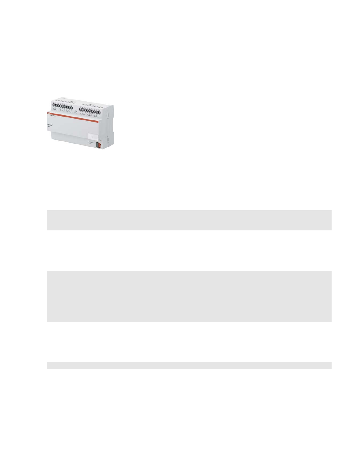
ABB i-bus KNX
Device technology
SA/S | 2CDC 505 056 D0208 9
2 Device technology
2.1 Switch Actuators SA/S x.6.1.1, 6 A, MDRC
SA/S
12.6.1.1
Switch Actuators SA/S
x.6.1.1 6 A are
modular installation devices in Pro
M
design for installation in the distribution
board. They are suitable for switching
resistive, inductive and capacit iv e loads.
The actuators can
switch up to
12
independent electrical loads via
floating contacts. The outputs are
connected using screw terminals in
groups of two
contacts for SA/S 8.6.1.1
and SA/S
12.6.1.1. SA/S 4.6.1.1 has one
terminal per output for power feed. Each
output is contr
olled separately via KNX,
regardless of the variant.
The device does not require an
additional power supply and is ready for
immediate use after the bus voltage
has been applied. The Switch Actuator
is parameterized via ETS. Connection
to KNX is implemented using the bus
connection terminal on the front.
2.1.1 Technical data
Supply
KNX bus voltage 21…32 V DC
Current consumption, bus < 12 mA
Power consumption
Maximum 250 mW
Rated output value
SA/S type 4.6.1.1 8.6.1.1 12.6.1.1
Current detection no no no
N
umber (floating contacts 2/group) 4 *) 8 12
U
n
rated voltage 250/440 V AC (50/60 Hz)
I
n
rated current (per output) 6 A 6 A 6 A
L
eakage loss per device at max. load 1.5 W 2.0 W 2.5 W
Output switching current
AC3
1)
operation (cos ϕ = 0.45)
To EN 60 947-4-1
6 A/230 V AC
AC3
1)
operation (cos ϕ = 0.8)
To EN 60 947-4-1
6 A/230 V AC
Fluorescent lighting load to EN 60 669-1 6 A/250 V AC (35 µF)2)
Minimum switching ca p acity 20 mA/5 V AC
10 mA/12 V AC
7 mA/24 V AC
Output service life
Mechanical service lif e
> 107
Electrical endurance
To IEC 60 947-4-1
A
C1
1)
(240 V/cos ϕ = 0.8)
> 10
5
AC31) (240 V/cos ϕ = 0.45)
> 1.5 x 10⁴
AC5a1) (240 V/cos ϕ = 0.45)
> 1.5 x 10⁴
*) Each output has one terminal for power feed.
2CDC 071 033 S0012
Page 7

ABB i-bus KNX
Device technology
10 2CDC 505 056 D0208 | SA/S
Output switching times 3)
Maximum output relay position change per
minute if all relays are switched simultane o usly.
The position changes should be distributed
equally within the minute.
4.6.1.1 8.6.1.1 12.6.1.1
60 30 20
Maximum output relay position change per
minute if only one relay is swit ched.
240 240 240
Connections
KNX
Loa
d circuits
Tightening torque
Operating and display elements
Programming button/LED
Degree of protection
IP 20
Protection class
II
Isolation category
Overvoltage category
Pol
lution degree
Via bus connection terminals,
0.8 mm Ø, solid
Universal head screw terminal (PZ 1)
0.2… 4 mm2 fine stranded, 2 x 0.2…2.5 mm2
0.2… 6 mm2 solid, 2 x 0.2…4 mm
2
max. 0.6 Nm
For assignment of physical address To EN 60
529
To EN 61 140
III to EN 60 664-1
2 to EN 60 664-1
KNX safety extra low voltage
SELV 24 V DC
Temperature range
Operation
Storage
Transport
- 5 °C…+45 °C
-25 °C…+55 °C
-25 °C…+70 °C
Ambient conditions
Maximum a ir humidity 95 %, no condensation allowed
Design
Modular installation device (MDRC) Modular installation device, ProM
SA/S t
ype 4.6.1.1 8.6.1.1 12.6.1.1
Di
mensions 90 x W x 64.5 mm (H x W x D)
Widt
h W in mm 72 108 144
Mou
nting width in units (18 mm modules) 4 6 8
Mounting depth in mm 64.5 64.5 64.5
Weight
in kg
0.13 0.24 0.3
Mounting
On 35 mm mounting rail
To EN 60 715
Mounting position
As required
Housing/color
Plastic housing, gray
Approvals
KNX to EN 50 090 -1, -2 Certification
CE mark
in accordance with the EMC guideline and
low voltage guideline
1)
Further information concerning electrical endurance to IEC 60 947-4-1 can be found at: AC1, AC3, AX, C-load specifications, p. 43
2)
The maximum inrush current peak may not be exceeded.
3)
The specifications apply only after the bus voltage has been applied to the device for at least 30 seconds. Typical relay delay is approx. 20 ms.
Page 8

ABB i-bus KNX
Device technology
SA/S | 2CDC 505 056 D0208 11
2.1.2 Lamp output load at 230 V AC
Lamps
Incande s cent lamp load 1,200 W
Fluorescent lamps T5/T8
Uncorrected
Parallel compensated
DUO circuit
800 W
300 W
350 W
Low-voltage halogen lamps
Inductive transform e r
Electronic transfor mer
Halogen lamps 230 V
800 W
1,000 W
1,000 W
Dulux lamp
Uncorrected
Parallel compensated
800 W
800 W
Mercury-vapor lamp
Uncorrected
Parallel compensated
1,000 W
800 W
Switching capacity (switchi ng conta c t )
Maximum peak inrush current Ip (150 µs)
Maximum peak inrush current I
p
(250 µs)
Maximum peak inrush current I
p
(600 µs)
200 A
160 A
100 A
Number of electronic ballasts (T5/T8, single
element)1)
18 W (ABB EVG 1 x 18 SF)
24 W (ABB EVG-T5 1 x 24 CY)
36 W (ABB EVG 1 x 36 CF)
58 W (ABB EVG 1 x 58 CF)
80 W (Helvar EL 1 x 80 SC)
10
10
7
5
3
1)
For multiple element lamps or other types, the number of electronic ballas ts mu s t be deter mined usi ng the peak inrush current of the electronic
ballasts, see Ballast calculation, p. 42
Device type Application program Maximum number of
communication objects
Maximum number of
group addresses
Maximum number of
associations
SA/S 4.6.1.1 Switch 4f 6A/…* 64 254 254
SA/S 8.6.1.1 Switch 8f 6A/…* 124 254 254
SA/S 12.6.1.1 Switch 12f 6A/…* 184 254 254
* … = current version number of the application program
Please note
ETS and the current version of the device application program are required for programming.
The current application program is available for download at www.abb.com/knx. After import into ETS
it can be found under ABB/Out put/Binary output xf 6A/…* (x = 4, 8 or 12).
The device does not support the locking function of a KNX device in ETS. If you inhibit access to all of
the project devices by using a BCU code, it has no effect on this device.
Data can still be read and programmed.
Page 9
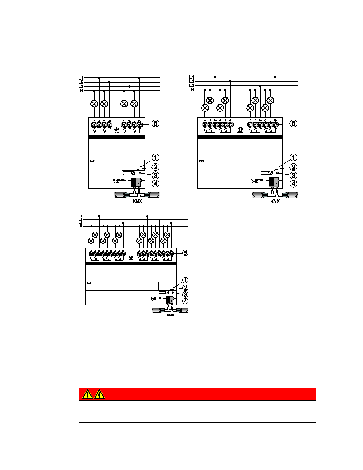
ABB i-bus KNX
Device technology
12 2CDC 505 056 D0208 | SA/S
2.1.3 Connection schematic SA/S x.6.1.1
1 Label carrier
2 Programming button
3 Programming LED
4 Bus connection terminal
5 Load current circuits, one screw terminal for phase connection per contact
Danger
Touch voltages.
Danger of injury.
Observe all-pole disconnection.
2CDC 072 07x F0011
Page 10

ABB i-bus KNX
Device technology
SA/S | 2CDC 505 056 D0208 13
2.1.4 Dimension drawing SA/S x.6.1.1
SA/S 4.6.1.1
SA/S 8.6.1.1
SA/S 12.6.1.1
Width W
Mounting width
(18 mm modules)
72 mm
4 units
108 mm
6 units
144 mm
8 units
2CDC 072 077 F0011
Page 11
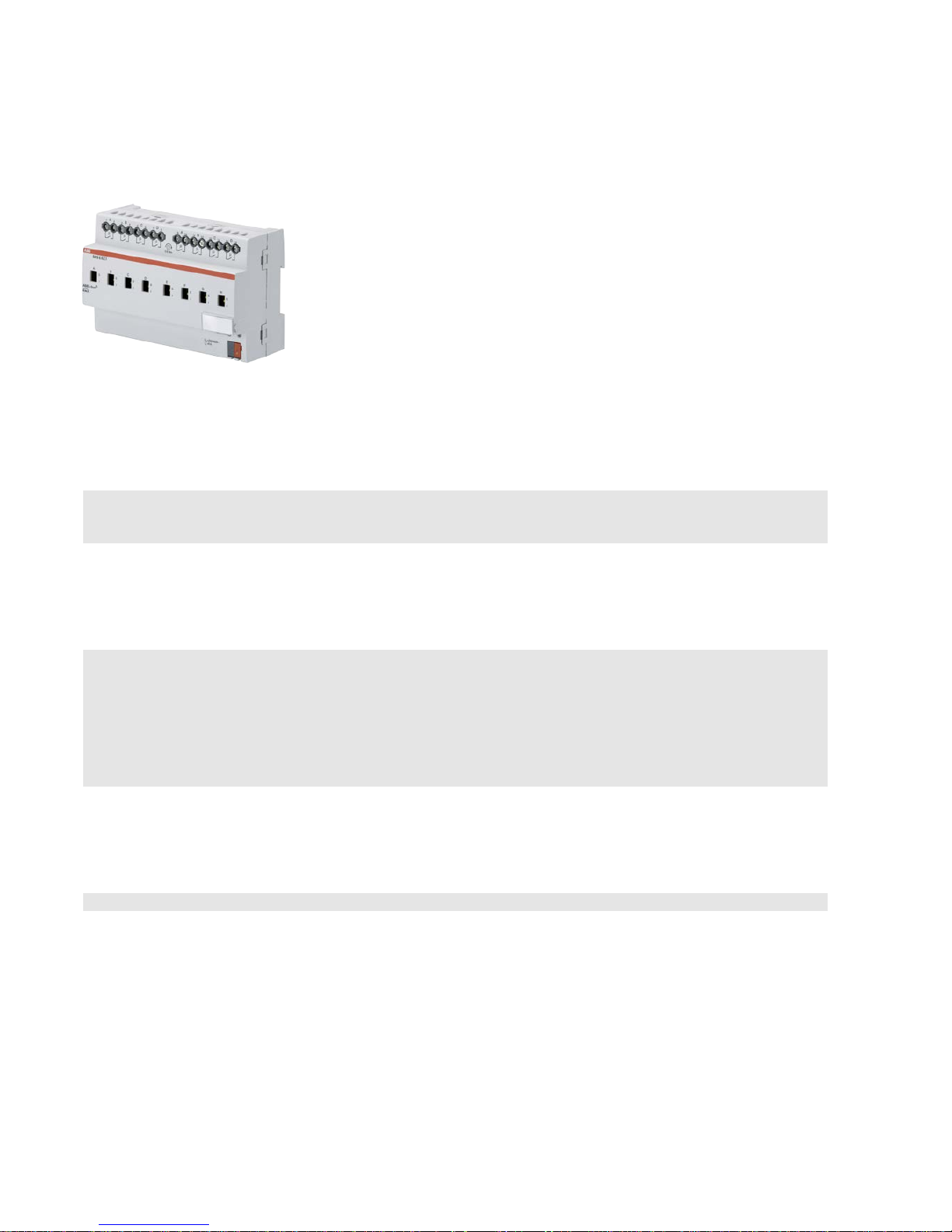
ABB i-bus KNX
Device technology
14 2CDC 505 056 D0208 | SA/S
2.2 Switch Actuators SA/S x.6.2.1, 6 A, manual, MDRC
SA/S
8.6.2.1
Switch Actuators SA/S
x.6.2.1, 6 A are
mod
ular installation devices in ProM
design for installation in the distribution
board. They are suitable for switching
resistive, inductive and capacit iv e loads as
well as fluorescent lamp loads (AX) to
EN
60 669.
The Switch Actuator can be actuated
manually
using a button. This
simultaneously indicates the contact
position.
The actuators can switch up to
12 independent electrical loads via
floating contacts. The connection of the
outputs is implemented using combohead screw terminals. Each output is
controlled separately via KNX.
The device does not require an
additional power supply and is ready for
immediate use after the bus voltage has
been applied.
The Switch Actuators are parameterized
via ETS. Connection to KNX is
implemented using the bus connection
terminal on the front.
2.2.1 Technical data
Supply
KNX bus voltage 21…31 V DC
Current consumption via bus < 12 mA
Power consumption via bus Maximum 250 mW
Rated output value
SA/S type 2.6.2.1 4.6.2.1 8.6.2.1 12.6.2.1
C
urrent detection no no no no
N
umber (floating contacts) 2 4 8 12
Un rated voltage
250/440 V AC (50/60 Hz)
In rated current
6 AX 6 AX 6 AX 6 AX
Leakage loss per device at max. load 0.9 W 1.2 W 1.5 W 3.9 W
Output switching current
AC3
1)
operation (cos ϕ = 0.45)
To EN 60 947-4-1
6 A/230 V AC
AC1
1)
operation (cos ϕ = 0.8)
To EN 60 947-4-1
6 A/230 V AC
Fluorescent lighting load to EN 60 669-1
6 AX/250 V AC (140 µF)2)
Minimum switching ca p acity 100 mA/12 V AC
100 mA/24 V AC
DC current switching capacity (resistive load) 6 A/24 V DC
Output service life
Mechanica l service life
> 3 x 10⁶
Electrical endurance
To IEC 60 947-4-1
A
C1
1)
(240 V/cos ϕ = 0.8)
> 105
AC31) (240 V/cos ϕ = 0.45)
> 3 x 10⁴
AC5a 1) (240 V/cos ϕ = 0.45)
> 3 x 10⁴
2CDC 071 001 S0013
Page 12

ABB i-bus KNX
Device technology
SA/S | 2CDC 505 056 D0208 15
Output switching times3)
SA/S type
Maximum output relay position change per
minute if all relays are switche d simultaneo usly.
The position changes should be distributed
equally within the minute.
2.6.2.1 4.6.2.1 8.6.2.1 12.6.2.1
60 30 15 10
Maximum output relay position change per
minute if only one relay is switched.
120 120 120 120
Connections
KNX Via bus connection terminals,
0.8 mm Ø, solid
L
oad circuits Universal head screw terminal (PZ 1)
0.2… 4 mm
2
fine stranded, 2 x 0.2…2.5 mm2
0.2… 6 mm
2
solid, 2 x 0.2…4 mm2
F
errules without/with plastic sleeves
0.25…2.5/4 mm
2
T
WIN ferrules
0.5…2.5 mm
2
Contact pin length min. 10 mm
T
ightening torque max. 0.6 Nm
Operating and display elements
Programming button/LED For assignment of the physical address
Contact position display Relay operator
Degree of protection
IP 20
To EN 60 529
Protection class
II To EN 61 140
Isolation category
Overvoltage category III to EN 60 664-1
P
ollution degree 2 to EN 60 664-1
KNX safety extra low voltage
SELV 24 V DC
Temperature range
Operation
Storage
Transport
- 5 °C…+45 °C
-25 °C…+55 °C
-25 °C…+70 °C
Ambient conditions
Maximum a ir humidity
95 %, no condensation allowed
Design
Modular installation device (MDRC)
Modular installation device, ProM
SA/S type 2.6.2.1 4.6.2.1 8.6.2.1 12.6.2.1
D
imensions 90 x W x 64.5 mm (H x W x D)
W
idth W in mm 36 72 144 216
M
ounting width in units (18 mm modules) 2 4 8 12
M
ounting depth in mm 64.5 64.5 64.5 64.5
Weight
in kg 0.15 0.25 0.46 0.65
Mounting
On 35 mm mounting rail To EN 60 715
Mounting position
any
Housing/color
Plastic housing, gray
Approvals
KNX to EN 50 090-1, -2
Certification
CE mark
in accordance with the EMC guideline and
low voltage guideline
1)
Further information concerning electrica l endurance to IEC 60 94 7-4-1 can be found at: AC1, AC3, AX, C-load specifications, p. 43
2)
The maximum inrush current peak may not be exceeded.
3)
The specifications apply only after the bus voltage has been applied to the device for at least 30 seconds. Typical relay delay is approx. 20 ms.
Page 13

ABB i-bus KNX
Device technology
16 2CDC 505 056 D0208 | SA/S
2.2.2 Lamp output load, 6 A
Lamps
Incande s cent lamp load 1,380 W
Fluorescent lamps T5/T8
Uncorrected
Parallel compensated
DUO circuit
1,380 W
1,380 W
1,380 W
Low-voltage halogen lamps
Inductive transform e r
Electronic transfor mer
Halogen lamps 230 V
1,200 W
1,380 W
1,380 W
Dulux lamp
Uncorrected
Parallel compensated
1,100 W
1,100 W
Mercury-vapor lamp
Uncorrected
Parallel compensated
1,380 W
1,380 W
Switching capacity (switchi ng conta c t )
Maximum peak inrush current Ip (150 µs)
Maximum peak inrush current Ip (250 µs)
Maximum peak inrush current Ip (600 µs)
400 A
320 A
200 A
Number of electronic ballasts (T5/T8, single
element)1)
18 W (ABB EVG 1 x 18 SF)
24 W (ABB EVG-T5 1 x 24 CY)
36 W (ABB EVG 1 x 36 CF)
58 W (ABB EVG 1 x 58 CF)
80 W (Helvar EL 1 x 80 SC)
23
23
14
11
10
1)
For multiple element lamps or other types, the number of electronic ballas ts mu s t be deter mined usi ng the peak inrush current of the electronic
ballasts, see
Ballast calculation, p. 42.
Device type Application program Maximum number of
communication objects
Maximum number of
group addresses
Maximum number of
associations
SA/S 2.6.2.1 Switch 2f 6AM/…* 34 254 254
SA/S 4.6.2.1 Swit ch 4f 6AM/…* 64 254 254
SA/S 8.6.2.1 Switch 8f 6AM/…* 124 254 254
SA/S 12.6.2.1 Switch 12f 6AM/…* 184 254 254
* … = current version number of the application program
Please note
ETS and the current version of the device application program are required for programming.
The current application program is available for download at www.abb.com/knx. After import into ETS it
can be found under ABB/Output/Binary output xf 6AM/…* (x = 2, 4, 8 or 12).
The device does not support the locking function of a KNX device in ETS. If you inhibit access to all of
the project devices by using a BCU code, it has no effect on this device.
Data can still be read and programmed.
Page 14
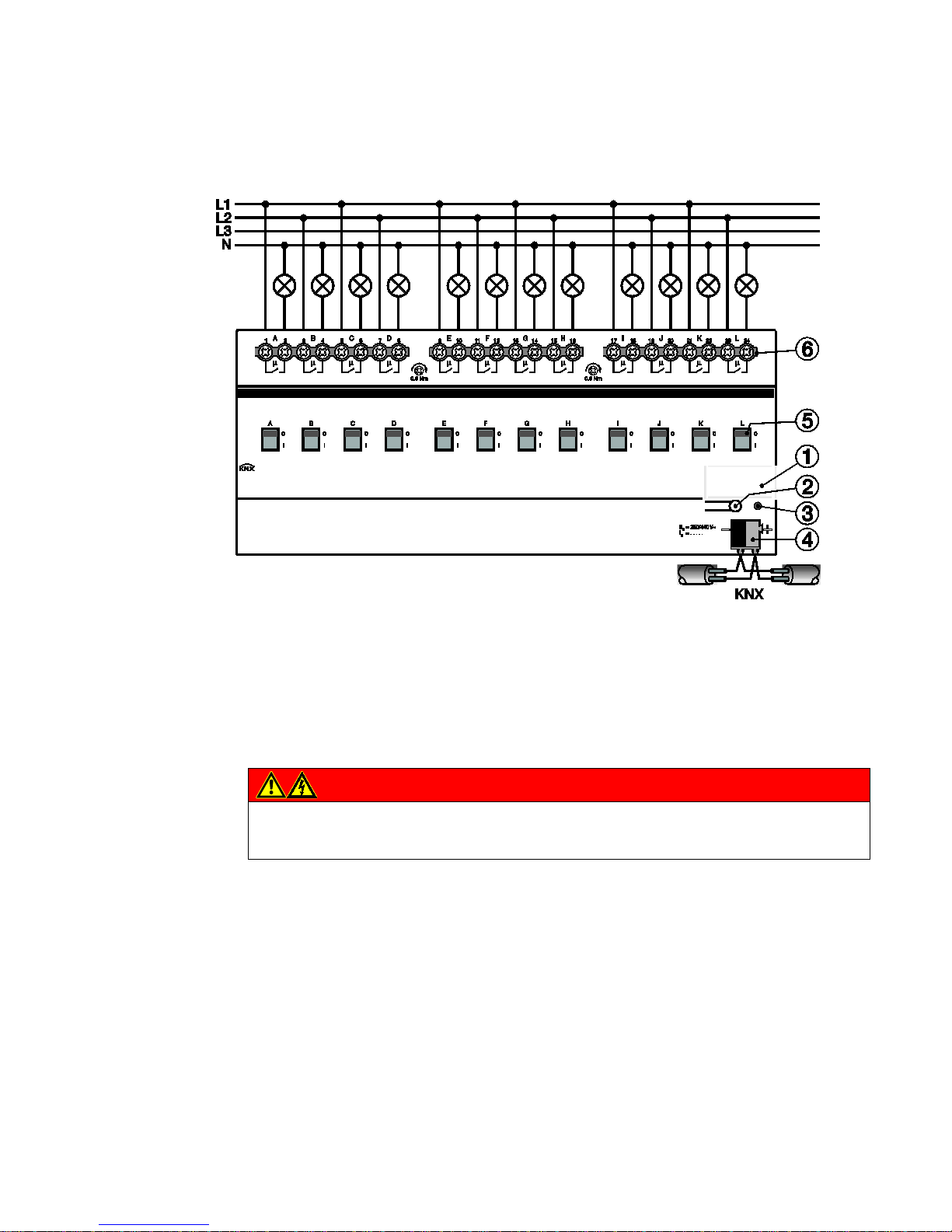
ABB i-bus KNX
Device technology
SA/S | 2CDC 505 056 D0208 17
2.2.3 Connection schematic SA/S x.6.2.1
1 Label carrier
2 Programming button
3 Programming LED
4 Bus connection terminal
5 Contact position display and manual operation
6 Load current circuits, for every 2 connection terminals
Danger
Touch voltages.
Danger of injury.
Observe all-pole disconnection.
2CDC 072 086 F0011
Page 15
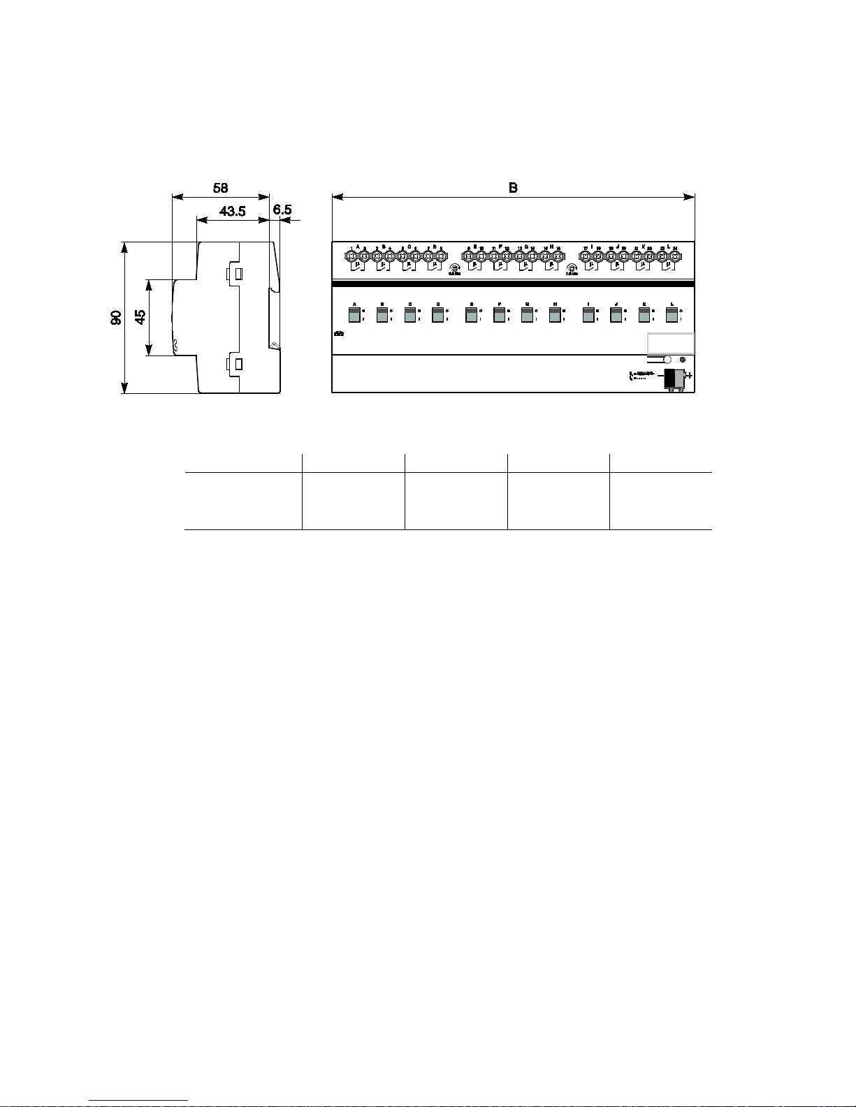
ABB i-bus KNX
Device technology
18 2CDC 505 056 D0208 | SA/S
2.2.4 Dimension drawing SA/S x.6.2.1
SA/S 2.6.2.1 SA/S 4.6.2.1 SA/S 8.6.2.1 SA/S 12.6.2.1
Width W
Mounting width
(18 mm modules)
36 mm
2 units
72 mm
4 units
144 mm
8 units
216 mm
12 units
2CDC 072 019 F0013
Page 16

ABB i-bus KNX
Device technology
SA/S | 2CDC 505 056 D0208 19
2.3 Switch Actuators SA/S x.10.2.1, 10 A, MDRC
SA/S
8.10.2.1
Switch Actuators SA
/S x.6.2.1, 10 A are
modular installation devices in Pro
M
design for installation in the distribution
board. They are suitable for switching
resistive, inductive and capacit iv e loads as
well as fluorescent lamp loads (AX) to
EN
60 669.
The Switch Actuator
can be actuated
manually using a button. This
simultaneously indicates the contact
position.
The Switch Actuators can switch up to
12 independent electrical loads via
floating contacts. The connection of the
outputs is implemented using combohead screw terminals. Each output is
controlled separately via KNX.
The device does not require an
additional power supply and is ready for
immediate use, after the bus voltage has
been applied.
The Switch Actuators are parameterized
via ETS. Connection to KNX is
implemented using the bus connection
terminal on the front.
2.3.1 Technical data
Supply
KNX bus voltage 21…31 V
Current consumption via bus < 12 mA
Power consumption via bus Maximum 250 mW
Rated output value
SA/S type
2.10.2.1 4.10.2.1 8.10.2.1 12.10.2.1
Current detection
no no no no
Number (floating contacts 2/group) 2 4 8 12
Un rated voltage 250/440 V AC (50/60 Hz)
I
n
rated current 10 AX 10 AX 10 AX 10 AX
L
eakage loss per device at max. load 1.5 W 2.0 W 2.5 W 6.5 W
Output switching current
AC3
1)
operation (cos ϕ = 0.45)
To EN 60 947-4-1
8 A / 230 V AC
AC1
1)
operation (cos ϕ = 0.8)
To EN 60 947-4-1
10 A / 230 V AC
Fluorescent lighting load to EN 60 669-1
Minimum switching ca p acity
DC current switching capacity (resistive load)
Output service life
Mechanica l service life
10 AX/250 V AC (140 µF)
2)
100 mA/12 V AC
100 mA/24 V AC
10 A/24 V DC
> 3 x 10⁶
Electrical endurance
To IEC 60 947-4-1
A
C1
1)
(240 V/cos ϕ = 0.8)
> 105
AC31) (240 V/cos ϕ = 0.45)
> 3 x 10⁴
AC5a 1) (240 V/cos ϕ = 0.45)
> 3 x 10⁴
2CDC 071 016 S0012
Page 17

ABB i-bus KNX
Device technology
20 2CDC 505 056 D0208 | SA/S
Output switching times3)
Maximum r elay position chan ge of output and
minute if all relays are switched simultane o usly.
The position changes should be distributed
equally within the minute.
2.10.2.1 4.10.2.1 8.10.2.1 12.10.2.1
60 30 15 10
Maximum output relay position change per
minute if only one relay is switched.
120 120 120 120
Connections
KNX
Via bus connection terminals,0.8 mm Ø, solid
Load current circuits (1 terminal per contact)
Universal head screw terminal (PZ 1)
0.2… 4 mm
2
fine stranded, 2 x 0.2…2.5 mm2
0.2… 6 mm
2
solid, 2 x 0.2…4 mm2
F
errules without/with plastic sleeves
0.25…2.5/4 mm
2
T
WIN ferrules
0.5…2.5 mm
2
Contact pin length min. 10 mm
Tightening torque max. 0.6 Nm
Operating and display elements
Programming button/LED For assignment of the physical address
Contact position display Relay operator
Degree of protection
IP 20 To EN 60 529
Protection class
II To EN 61 140
Isolation category
Overvoltage category III to EN 60 664-1
Pollution degree
2 to EN 60 664-1
KNX safety extra low voltage
SELV 24 V DC
Temperature range
Operation
Storage
Transport
- 5 °C…+45 °C
-25 °C…+55 °C
-25 °C…+70 °C
Ambient conditions
Maximum a ir humidity 95 %, no condensation allowed
Design
Modular installation device (MDRC) Modular installation device, ProM
SA
/S type 2.10.2.1 4.10.2.1 8.10.2.1 12.10.2.1
Dimensions
90 x W x 64.5 mm (H x W x D)
Width W in mm
36 72 144 216
Mounting width in units (18 mm modules) 2 4 8 12
Mounting depth in mm 64.5 64.5 64.5 64.5
Weight
in kg 0.15 0.25 0.46 0.65
Mounting
On 35 mm mounting rail To EN 60 715
Mounting position
As required
Housing/color
Plastic housing, gray
Approvals
KNX to EN 50 090-1, -2
Certification
CE mark
in accordance with the EMC guideline and
low voltage guideline
1)
Further information concerning electrical endurance to IEC 60 947-4-1 can be found at: AC1, AC3, AX, C-load specif ications, p. 43
2)
The maximum inrush current peak may not be exceeded.
3)
The specifications apply only after the bus voltage has been applied to the device for at least 30 seconds. Typical relay delay is approx. 20 ms.
Page 18

ABB i-bus KNX
Device technology
SA/S | 2CDC 505 056 D0208 21
2.3.2 Lamp output load 10 A
Lamps
Incande s cent lamp load 2,500 W
Fluorescent lamps T5/T8
Uncorrected
Parallel compensated
DUO circuit
2,500 W
1,500 W
1,500 W
Low-voltage halogen lamps
Inductive transform e r
Electronic transfor mer
Halogen lamps 230 V
1,200 W
1,500 W
2,500 W
Dulux lamp
Uncorrected
Parallel compensated
1,100 W
1,100 W
Mercury-vapor lamp
Uncorrected
Parallel compensated
2,000 W
2,000 W
Switching capacity (switchi ng conta c t )
Maximum peak inrush current I
p
(150 µs)
Maximum peak inrush current I
p
(250 µs)
Maximum peak inrush current I
p
(600 µs)
400 A
320 A
200 A
Number of electronic ballasts (T5/T8, single
element)1)
18 W (ABB EVG 1 x 18 SF)
24 W (ABB EVG-T5 1 x 24 CY)
36 W (ABB EVG 1 x 36 CF)
58 W (ABB EVG 1 x 58 CF)
80 W (Helvar EL 1 x 80 SC)
23
23
14
11
10
1)
For multiple element lamps or other types, the number of electronic ballas ts mu s t be deter mined usi ng the peak inrush current of the electronic
ballasts, see
Ballast calculation, p. 42.
Device type Application program Maximum number of
communication objects
Maximum number of
group addresses
Maximum number of
associations
SA/S 2.10.2.1 Switch 2f 10 A/…* 34 254 254
SA/S 4.10.2.1 Switch 4f 10 A/…* 64 254 254
SA/S 8.10.2.1 Switch 8f 10 A/…* 124 254 254
SA/S 12.10.2.1 Switch 12f 10A/…* 184 254 254
* … = current version number of the application program
Please note
ETS and the current version of the device application program are required for programming.
The current application program is available for download at www.abb.com/knx. After import into ETS,
it is available in ETS under ABB/Output/Binary output xf 10A/…* (x = 2, 4, 8 or 12).
The device does not support the locking function of a KNX device in ETS. If you inhibit access to all of
the project devices by using a BCU code, it has no effect on this device.
Data can still be read and programmed.
Page 19
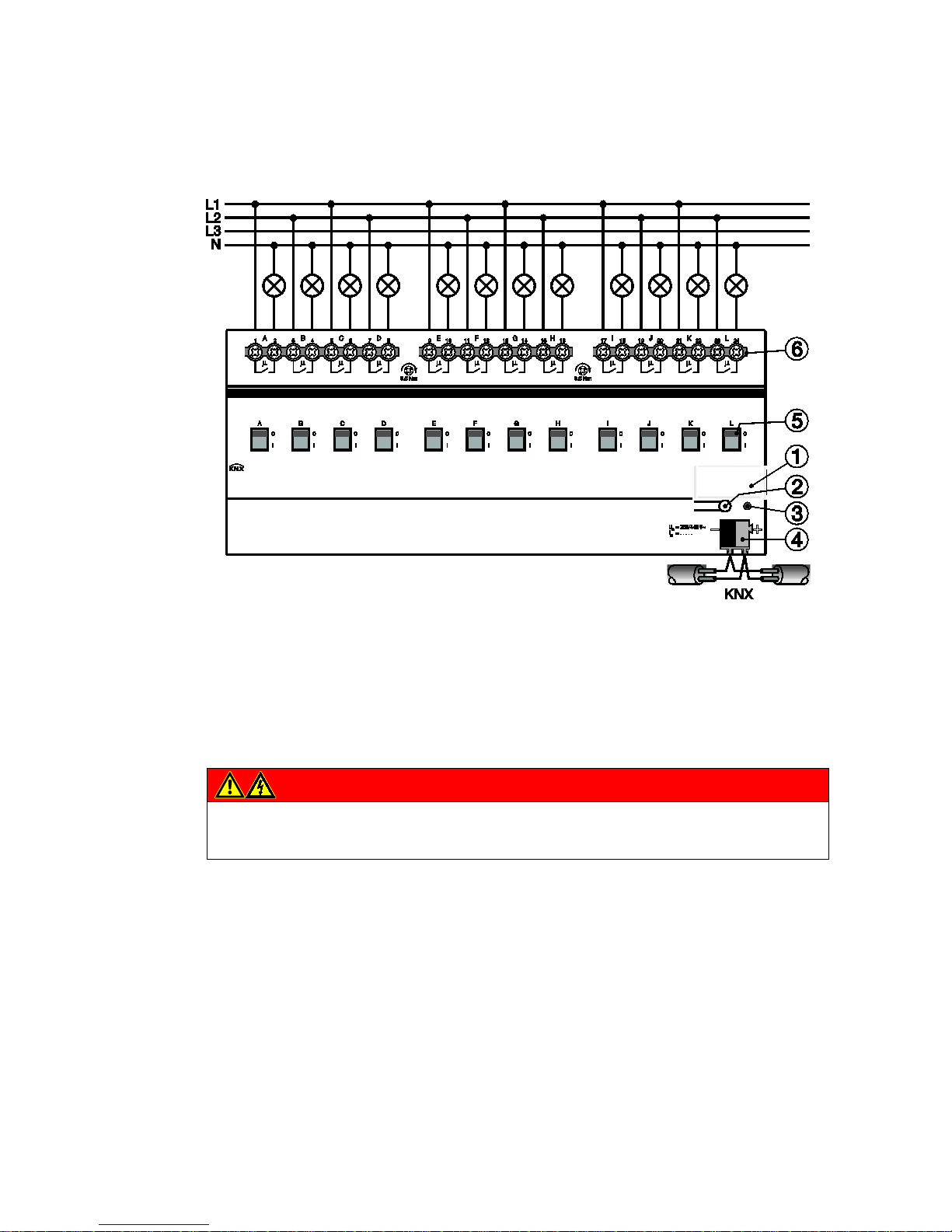
ABB i-bus KNX
Device technology
22 2CDC 505 056 D0208 | SA/S
2.3.3 Connection schematic SA/S x.10.2.1
1 Label carrier
2 Programming button
3 Programming LED
4 Bus connection terminal
5 Contact position display and manual operation
6 Load current circuits, for every 2 connection terminals
Danger
Touch voltages.
Danger of injury.
Observe all-pole disconnection.
2CDC 072 086 F0011
Page 20
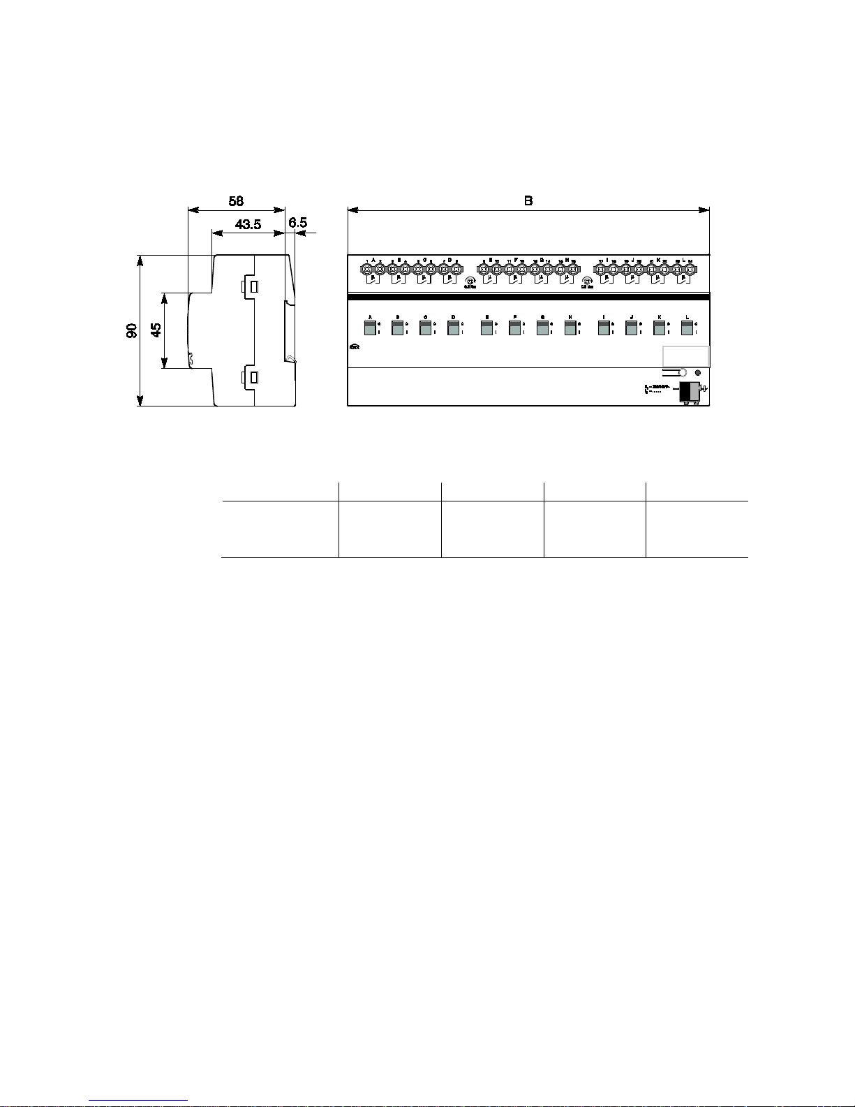
ABB i-bus KNX
Device technology
SA/S | 2CDC 505 056 D0208 23
2.3.4 Dimension drawing SA/S x.10.2.1
SA/S 2.10.2.1
SA/S 4.10.2.1
SA/S 8.10.2.1
SA/S 12.10.2.1
Width W
Mounting width
(18 mm modules)
36 mm
2 units
72 mm
4 units
144 mm
8 units
216 mm
12 units
2CDC 072 019 F0013
Page 21
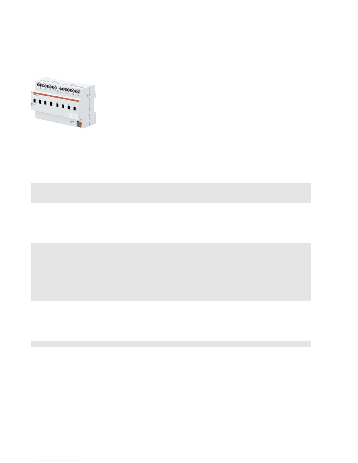
ABB i-bus KNX
Device technology
24 2CDC 505 056 D0208 | SA/S
2.4 Switch Actuators SA/S x.16.2.1, 16 A MDRC
SA/S
8.16.2.1
Switch Actuators SA/S x.16.2.1, 16 A are
modular installation devices in ProM
design for installation in the distribution
board. They are especially suitable for
switching resistive loads.
The Switch Actuator can be actuated
manually using a button. This
simultaneously indicates the c ont a ct
position.
The Switch Actuators can switch up to
12 independent electrical loads via
floating contacts. The connection of the
outputs is implemented using combohead screw terminals. Each output is
controlled separately via KNX.
The device does not require an
additional power supply and is ready for
immediate use, after the bus voltage has
been applied.
The Switch Actuators are parameterized
via ETS. Connection to KNX is
implemented using the bus connection
terminal on the front.
2.4.1 Technical data
Supply
KNX bus voltage 21…31 V DC
Current consumption via bus < 12 mA
Power consumption via bus Maximum 250 mW
Rated output value
SA/S type 2.16.2.1 4.16.2.1 8.16.2.1 12.16.2.1
Current detection
no no no no
Number (floating contacts 2/group)
2 4 8 12
Un rated voltage 250/440 V AC (50/60 Hz)
In rated current 16 A 16 A 16 A 16 A
L
eakage loss per device at max. load 2.0 W 4.0 W 8.0 W 12.0 W
Output switching current
AC3
1)
operation (cos ϕ = 0.45)
To EN 60 947-4-1
8 A / 230 V AC
AC1
1)
operation (cos ϕ = 0.8)
To EN 60 947-4-1
16 A/230 V AC
Fluorescent lighting load to EN 60 669-1
Minimum switching ca p acity
DC current switching capacity (resistive load)
Output service life
Mechanica l service life
16 AX/250 V AC (70 µF)
2)
100 mA/12 V AC
100 mA/24 V AC
16 A/24 V DC
> 3 x 10⁶
Electrical endurance
To IEC 60 947-4-1
AC11) (240 V/cos ϕ = 0.8)
> 105
AC31) (240 V/cos ϕ = 0.45)
> 3 x 10⁴
AC5a1) (240 V/cos ϕ = 0.45)
> 3 x 10⁴
2CDC 071 017 S0012
Page 22

ABB i-bus KNX
Device technology
SA/S | 2CDC 505 056 D0208 25
Output switching times3)
Maximum r elay position chan ge of output and
minute if all relays are switched simultane o usly.
The position changes should be distributed
equally within the minute.
2.10.2.1 4.10.2.1 8.10.2.1 12.10.2.1
60 30 15 10
Maximum output relay position change per
minute if only one relay is switched.
120 120 120 120
Connections
KNX
Via bus connection terminals,0.8 mm Ø, solid
Load current circuits (1 terminal per contact)
Universal head screw terminal (PZ 1)
0.2… 4 mm
2
fine stranded, 2 x 0.2…2.5 mm2
0.2… 6 mm
2
solid, 2 x 0.2…4 mm2
F
errules without/with plastic sleeves
0.25…2.5/4 mm
2
T
WIN ferrules
0.5…2.5 mm
2
Contact pin length min. 10 mm
Tightening torque max. 0.6 Nm
Operating and display elements
Programming button/LED For assignment of the physical address
Contact position display Relay operator
Degree of protection
IP 20 To EN 60 529
Protection class
II To EN 61 140
Isolation category
Overvoltage category III to EN 60 664-1
Pollution degree
2 to EN 60 664-1
KNX safety extra low voltage
SELV 24 V DC
Temperature range
Operation
Storage
Transport
- 5 °C…+45 °C
-25 °C…+55 °C
-25 °C…+70 °C
Ambient conditions
Maximum a ir humidity 95 %, no condensation allowed
Design
Modular installation device (MDRC) Modular installation device, ProM
SA/
S type 2.10.2.1 4.10.2.1 8.10.2.1 12.10.2.1
Dimensions
90 x W x 64.5 mm (H x W x D)
Width W in mm
36 72 144 216
Mounting width in units (18 mm modules) 2 4 8 12
Mounting depth in mm 64.5 64.5 64.5 64.5
Weight
in kg 0.15 0.25 0.46 0.65
Mounting
On 35 mm mounting rail To EN 60 715
Mounting position
any
Housing/color
Plastic housing, gray
Approvals
KNX to EN 50 090-1, -2
Certification
CE mark
in accordance with the EMC guideline and
low voltage guideline
1)
Further information concerning electrical endurance to IEC 60 947-4-1 can be found at: AC1, AC3, AX, C-load specifications, p. 43
2)
The maximum inrush current peak may not be exceeded.
3)
The specifications apply only after the bus voltage has been applied to the device for at least 30 seconds. Typical relay delay is approx. 20 ms.
Page 23

ABB i-bus KNX
Device technology
26 2CDC 505 056 D0208 | SA/S
2.4.2 Lamp output load 16 A
Lamps
Incande s cent lamp load 2,500 W
Fluorescent lamps T5/T8
Uncorrected
Parallel compensated
DUO circuit
2,500 W
1,500 W
1,500 W
Low-voltage halogen lamps
Inductive transform e r
Electronic transfor mer
Halogen lamps 230 V
1,200 W
1,500 W
2,500 W
Dulux lamp
Uncorrected
Parallel compensated
1,100 W
1,100 W
Mercury-vapor lamp
Uncorrected
Parallel compensated
2,000 W
2,000 W
Switching capacity (switchi ng conta c t )
Maximum peak inrush current I
p
(150 µs)
Maximum p eak inrush curren t I
p
(250 µs)
Maximum peak inrush current I
p
(600 µs)
400 A
320 A
200 A
Number of electronic ballasts (T5/T8, single
element)1)
18 W (ABB EVG 1 x 18 SF)
24 W (ABB EVG-T5 1 x 24 CY)
36 W (ABB EVG 1 x 36 CF)
58 W (ABB EVG 1 x 58 CF)
80 W (Helvar EL 1 x 80 SC)
23
23
14
11
10
1)
For multiple element lamps or other types, the number of electronic ballas ts mu s t be deter mined usi ng the peak inrush
current of the electronic ballasts, see
Ballast calculation, p. 42
Device type
Application program
Maximum number of
communication objects
Maximum number of
group addresses
Maximum number of
associations
SA/S 2.10.2.1 Switch 2f 10 A/…* 34 254 254
SA/S 4.10.2.1
Switch 4f 10A/…*
64
254
254
SA/S 8.10.2.1
Switch 8f 10A/…*
124
254
254
SA/S 12.10.2.1 Switch 12f 10A/…* 184 254 254
* … = current version number of the application program
Please note
ETS and the current version of the device application program are required for programming.
The current application program is available for download at www.abb.com/knx. After import into ETS,
it is available in ETS under ABB/Output/Binary output xf 10A/…* (x = 2, 4, 8 or 12).
The device does not support the locking function of a KNX device in ETS. If you inhibit access to all
devices of the project with a BCU code, it has no effect on this device.
Data can still be read and programmed.
Page 24

ABB i-bus KNX
Device technology
SA/S | 2CDC 505 056 D0208 27
2.4.3 Connection schematic SA/S x.16.2.1
1 Label carrier
2 Programming button
3 Programming LED
4 Bus connection terminal
5 Contact position display and manual operation
6 Load current circuits, for every 2 connection terminals
Danger
Touch voltages.
Danger of injury.
Observe all-pole disconnection.
2CDC 072 086 F0011
Page 25

ABB i-bus KNX
Device technology
28 2CDC 505 056 D0208 | SA/S
2.4.4 Dimension drawing SA/S x.16.2.1
SA/S 2.16.2.1
SA/S 4.16.2.1
SA/S 8.16.2.1
SA/S 12.16.2.1
Width W
Mounting width
(18 mm modules)
36 mm
2 units
72 mm
4 units
144 mm
8 units
216 mm
12 units
2CDC 072 019 F0013
Page 26

ABB i-bus KNX
Device technology
SA/S | 2CDC 505 056 D0208 29
2.5 Switch Actuator SA/S 16.5.1, 16/20 A, MDRC
SA/S
12.16.5.1
Switch Actuat
ors SA/S x.16.5.1, 16/20 A
are modular installation devices in Pro
M
design for installation in the distribution
board. They are especially suitable for
switching loads with high peak inrush
currents such as lighting equipment with
compensation capacitors o
r fluorescent
lamp loads (AX) to EN
60 669.
Manual actuation of the Switch Actuator is
possible using a button. This
simultaneously indicates the contact
position.
The Switch Actuators can switch up to
12 independent electrical loads via
floating contacts. The maximum load
current per output is 20 A. The
connection of the outputs is implemented
using combo-
head screw terminals. Each
output is controlled separately via KNX.
The devices do not require an additional
power supply and are ready for
immediate use, after the bus voltage
has
been applied.
The Switch Actuators are parameterized
via ETS. Connection to KNX is
implemented using the bus connection
terminal on the front.
2.5.1 Technical data
Supply
KNX bus voltage 21…31 V DC
Current consumption via bus
< 12 mA
Power consumption via bus
Maximum 250 mW
Rated output value
SA/S type 2.16.5.1 4.16.5.1 8.16.5.1 12.16.5.1
Current detection no no no no
N
umber (floating contacts) 2 4 8 12
U
n
rated voltage 250/440 V AC (50/60 Hz)
I
n
rated current 16/20 AX, C-load
L
eakage loss per device at max. load 16 A 2.0 W 4.0 W 8.0 W 12 W
L
eakage loss per device at max. load 20 A 3.0 W 5.5 W 11.0 W 16 W
Output switching current
AC3
1)
operation (cos ϕ = 0.45)
To EN 60 947-4-1
16 A/230 V AC
AC1
1)
operation (cos ϕ = 0.8)
To EN 60 947-4-1
16/20 A/230 V AC
Fluorescent lighting load to EN 60 669-1 16/20 AX/250 V AC (200 µF)2)
Minimum switching ca p acity 100 mA/12 V AC
100 mA/24 V AC
DC current switching capacity (resistive load) 20 A/24 V DC
Output service life
Mechanical service life > 106
E
lectrical endurance to IEC 60 947-4-1
AC11) (240 V/cos ϕ = 0.8)
> 105
AC31) (240 V/cos ϕ = 0.45)
> 3 x 10⁴
A
C5a
1)
(240 V/cos ϕ = 0.45)
> 3 x 10⁴
2CDC 071 001 S0011
Page 27

ABB i-bus KNX
Device technology
30 2CDC 505 056 D0208 | SA/S
Output switching times3)
Maximum r elay position chan ges
per output per minute if all
relays are switched simultaneously.
Position changes should be
distributed equally within the minute.
2.16.5.1 4.16.5.1 8.16.5.1 12.16.5.1
30 15 7 5
Maximum r elay position chan ges
per output per minute if only
one relay is switched.
60 60 60 60
Connections
KNX Via bus connection terminals,
0.8 mm Ø, solid
L
oad circuits Universal head screw terminal (PZ 1)
0.2… 4 mm
2
fine stranded, 2 x 0.2…2.5 mm2
0.2… 6 mm
2
solid, 2 x 0.2…4 mm2
F
errules without/with plastic sleeves
0.25…2.5/4 mm
2
TWIN ferrules
0.5…2.5 mm
2
Contact pin length min. 10 mm
T
ightening torque max. 0.6 Nm
Operating and display elements
Programming button/LED For assignment of the physical address
Contact position display Relay operator
Degree of protection
IP 20
To EN 60 529
Protection class
II
To EN 61 140
Isolation category
Overvoltage category III to EN 60 664-1
P
ollution degree 2 to EN 60 664-1
KNX safety extra low voltage
SELV 24 V DC
Temperature range
Operation
Storage
Transport
- 5 °C…+45 °C
-25…+55 °C
-25…+70 °C
Ambient conditions
Maximum a ir humidity
95 %, no condensation allowed
Design
Modular installation device (MDRC) 2.16.5.1 4.16.5.1 8.16.5.1 12.16.5.1
Dimensions 90 x W x 64.5 mm (H x W x D)
W
idth W in mm 36 72 144 216
M
ounting width in units (18 mm modules) 2 4 8 12
M
ounting depth in mm 64.5 64.5 64.5 64.5
Weight
in kg 0.2 0.34 0.64 0.75
Mounting
On 35 mm mounting rail
To EN 60 715
Mounting position
any
Housing/color
Plastic housing, gray
Approvals
KNX to EN 50 090-1, -2 Certification
CE mark
in accordance with the EMC guideline and
low voltage guideline
1)
Further information concerning electrical endurance to IEC 60 947-4-1 can be found at: AC1, AC3, AX, C-load specifications, p. 43
2)
The maximum inrush current peak may not be exceeded.
3)
The specifications apply only after the bus voltage has been applied to the device for at least 30 seconds. Typical relay delay is approx. 20 ms.
Page 28

ABB i-bus KNX
Device technology
SA/S | 2CDC 505 056 D0208 31
2.5.2 Lamp output load 16/20 A
Lamps
Incande s cent lamp load 3,680 W
Fluorescent lamps T5/T8
Uncorrected
Parallel compensated
DUO circuit
3,680 W
2,500 W
3,680 W
Low-voltage halogen lamps
Inductive transformer
Electronic transfor mer
Halogen lamps 230 V
2,000 W
2,500 W
3,680 W
Dulux lamp
Uncorrected
Parallel compensated
3,680 W
3,000 W
Mercury-vapor lamp
Uncorrected
Parallel compensated
3,680 W
3,680 W
Switching capacity (switchi ng conta c t )
Maximum peak inrush current I
p
(150 µs)
Maximum peak inrush current I
p
(250 µs)
Maximum peak inrush current I
p
(600 µs)
600 A
480 A
300 A
Number of electronic ballasts (T5/T8, single
element)1)
18 W (ABB EVG 1 x 18 SF)
24 W (ABB EVG-T5 1 x 24 CY)
36 W (ABB EVG 1 x 36 CF)
58 W (ABB EVG 1 x 58 CF)
80 W (Helvar EL 1 x 80 SC)
26
2)
26
2)
22
12
2)
102)
1)
For multiple element lamps or other types, the number of electronic ballas ts mu s t be deter mined usi ng the peak inrush current of the electronic
ballasts, see
Ballast calculation, p. 42.
2)
The number of ballasts is limited by protection with B16 circuit-breakers.
Device type
Application program
Maximum number of
communication objects
Maximum number of
group addresses
Maximum number of
associations
SA/S 2.16.5.1 Switch 2f 16C/…* 34 254 254
SA/S 4.16.5.1
Switch 4f 16C/…*
64
254
254
SA/S 8.16.5.1
Switch 8f 16C/…*
124
254
254
SA/S 12.16.5.1 Switch 12f 16C/…* 184 254 254
* … = current version number of the application program
Please note
ETS and the current version of the device application program are required for programming.
The current application program is available for download at www.abb.com/knx. After import into ETS,
it is available in ETS under ABB/Output/Binary output xf 16C/…* (x = 2, 4, 8 or 12).
The device does not support the locking function of a KNX device in ETS. If you inhibit access to all of
the project devices by using a BCU code, it has no effect on this device.
Data can still be read and programmed.
Page 29
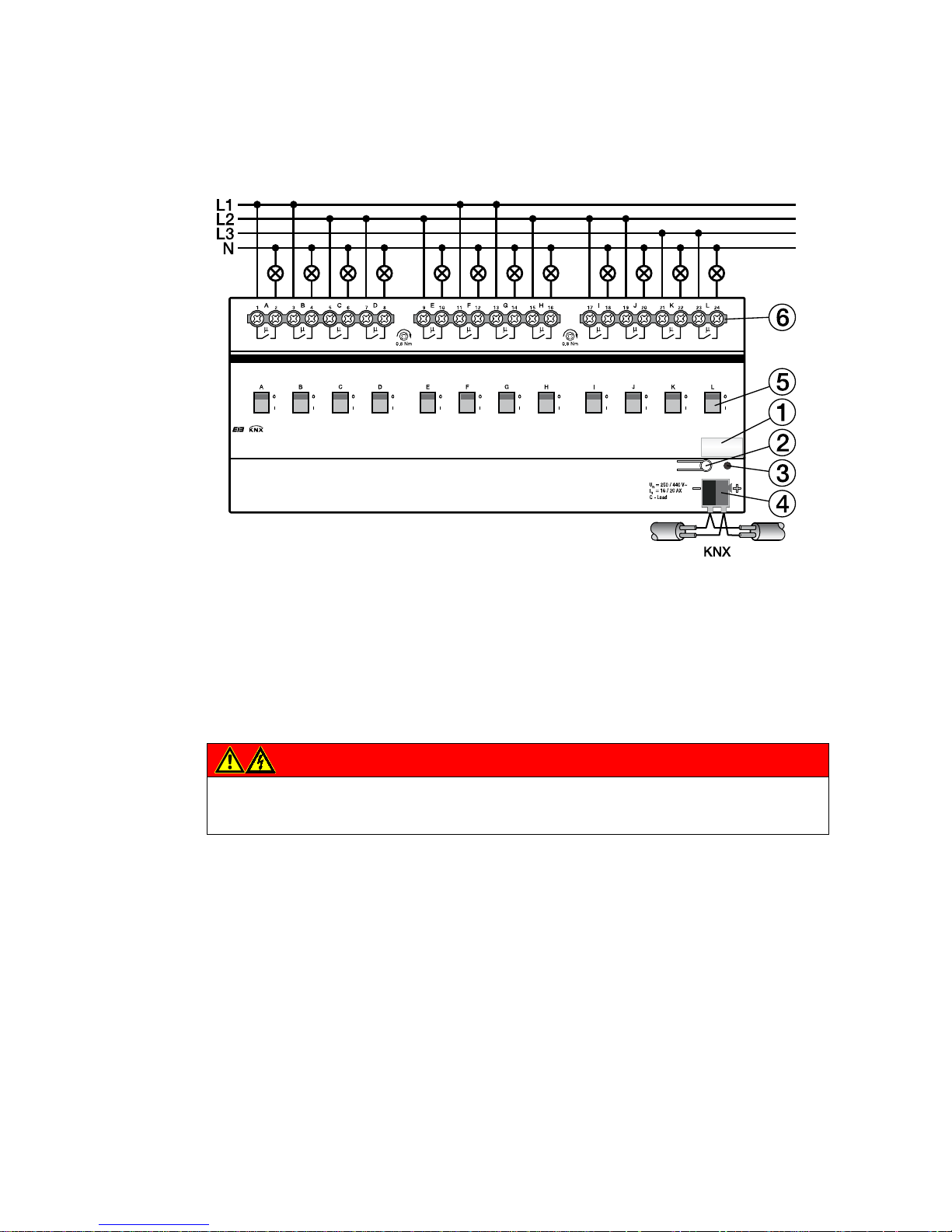
ABB i-bus KNX
Device technology
32 2CDC 505 056 D0208 | SA/S
2CDC 072 177 F0009
2.5.3 Connection schematic SA/S 12.16.5.1
1 Label carrier
2 Programming button
3 Programming LED
4 Bus connection terminal
5 Contact position display and manual operation
6 Load current circuits, for every 2 connection terminals
Danger
Touch voltages.
Danger of injury.
Observe all-pole disconnection.
Page 30
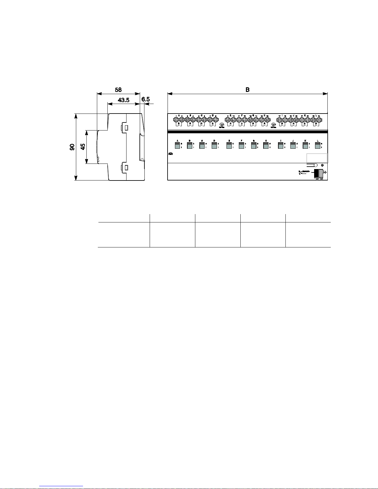
ABB i-bus KNX
Device technology
SA/S | 2CDC 505 056 D0208 33
2.5.4 Dimension drawing SA/S 12.16.5.1
SA/S 2.16.5.1 SA/S 4.16.5.1 SA/S 8.16.5.1 SA/S 12.16.5.1
Width W
Mounting width
(18 mm modules)
36 mm
2 units
72 mm
4 units
144 mm
8 units
216 mm
12 units
2CDC 072 019 F0013
Page 31

ABB i-bus KNX
Device technology
34 2CDC 505 056 D0208 | SA/S
2.6 Switch Actuators SA/S x.16.6.1, 16/20 A, MDRC
SA/S
8.16.6.1
Switch Actuators SA/S
x.16.6.1, 16/20 A
are modular installation devices in Pro
M
design for installation in the distribution
board. They a
re especially suitable for
switching loads with high peak inrush
currents such as lighting equipment with
compensation capacitors or fluores cent
lamp loads (AX) to EN
60 669.
The Switch Actuators feature one load
current detection per output.
The maximum l
oad current per output is
20 A.
The Switch Actuator can be actuated
manually using a button. This
simultaneously indicates the contact
position.
The Switch Actuators can switch up to
12 independent electrical loads via
floating contacts. The maximum load
current per output is 20 A. The
connection of the outputs is implemented
using combo-
head screw terminals. Each
output is controlled separately via KNX.
Individual outputs on SA/S x.16.6.1
devices can be copied or exchanged to
minimize programming work.
The device does not require an
additional power supply and is ready for
immediate use, after the bus voltage has
been applied.
The Switch Actuators are parameterized
via ETS. Connection to KNX is
implemented using the bus connection
terminal on the front.
2.6.1 Technical data
Supply
KNX bus voltage 21…31 V DC
Current consumption via bus
< 12 mA
Power consumption via bus
Maximum 250 mW
Rated output value
SA/S type 2.16.6.1 4.16.6.1 8.16.6.1 12.16.6.1
C
urrent detection yes yes yes yes
N
umber (floating contacts 2/group) 2 4 8 12
U
n
rated voltage 250/440 V AC (50/60 Hz)
I
n
rated current 16/20 AX, C-load
L
eakage loss per device at max. load 16 A 2.0 W 4.0 W 8.0 W 12.0 W
Leakage loss per device at max. load 20 A
3.0 W 5.5 W 11.0 W 16.0 W
Output switching current
AC3
1)
operation (cos ϕ = 0.45)
To EN 60 947-4-1
16 A/230 V AC
AC1
1)
operation (cos ϕ = 0.8)
To EN 60 947-4-1
16/20 A/230 V AC
Fluorescent lighting load to EN 60 669-1 16/20 AX/250 V AC (200 µF)2)
Minimum switching ca p acity 100 mA/12 V AC
100 mA/24 V AC
DC current switching capacity (resistive load) 20 A/24 V DC
2CDC 071 006 S0010
Page 32

ABB i-bus KNX
Device technology
SA/S | 2CDC 505 056 D0208 35
Output service life
Mechanica l service life
> 106
Electrical endurance
To IEC 60 947-4-1
AC11) (240 V/cos ϕ = 0.8)
> 105
AC31) (240 V/cos ϕ = 0.45)
> 3 x 10⁴
AC5a1) (240 V/cos ϕ = 0.45)
> 3 x 10⁴
Current detection (load current )
Detection range (sine effective value)
0.02…20 A
Accuracy +/- 2 % of actual current value (sine) and
+/- 20 mA
Frequency 50/60 Hz
2 byte representation (figure value, DTP 7.012)
or 4 byte representation (floating value, DTP
14.019)
in mA
M
easurement speed:
– Low-pass filter transient response with τ
– Scanning frequency of the current value
3
00 ms
320 ms
Output switching times3)
Maximum r elay position chan ges
per output per minute if all
relays are switched simultaneously.
The position changes should be distributed
equally within the minute.
2.16.6.1 4.16.6.1 8.16.6.1 12.16.6.1
30 15 7 5
Maximum r elay position chan ges
per output per minute if only
one relay is switched.
60 60 60 60
Connections
KNX Via bus connection terminals,
0.8 mm Ø, solid
Load circuits Universal head screw terminal (PZ 1)
0.2… 4 mm
2
fine stranded, 2 x 0.2…2.5 mm2
0.2… 6 mm
2
solid, 2 x 0.2…4 mm2
F
errules without/with plastic sleeves
0.25…2.5/4 mm
2
T
WIN ferrules
0.5…2.5 mm
2
Contact pin length min. 10 mm
Operating and display elements
Programming button/LED For assignment of the physical address
Contact position display Relay operator
Degree of protection
IP 20 To EN 60 529
Protection class
II To EN 61 140
Isolation category
Overvoltage category
III to EN 60 664-1
Pollution degree
2 to EN 60 664-1
KNX safety extra low voltage
SELV 24 V DC
Temperature range
Operation
Storage
Transport
- 5 °C…+45 °C
-25 °C…+55 °C
-25 °C…+70 °C
Page 33

ABB i-bus KNX
Device technology
36 2CDC 505 056 D0208 | SA/S
Ambient conditions
Maximum a ir humidity
95 %, no condensation allowed
Design
Modular installation device (MDRC) Modular installation device, ProM
SA/S type 2.16.6.1 4.16.6.1 8.16.6.1 12.16.6.1
D
imensions 90 x W x 64.5 mm (H x W x D)
W
idth W in mm 36 72 144 216
M
ounting width in units (18 mm modules) 2 4 8 12
M
ounting depth in mm 64.5 64.5 64.5 64.5
Weight
in kg
0.2 0.34 0.64 0.83
Mounting
On 35 mm mounting rail
To EN 60 715
Mounting position
As required
Housing/color
Plastic housing, gray
Approvals
KNX to EN 50 090-1, -2 Certification
CE mark
in accordance with the EMC guideline and
low voltage guideline
1)
Further information concerning electrical endurance to IEC 60 947-4-1 can be found at:AC1, AC3, AX, C-load specifications, p. 43
2)
The maximum inrush current peak may not be exceeded.
3)
The specifications apply only after the bus voltage has been applied to the device for at least 30 seconds. Typical relay delay is approx. 20 ms.
2.6.2 Lamp output load 16/20 A
Lamps
Incande s cent lamp load 3,680 W
Fluorescent lamps T5/T8
Uncorrected
Parallel compensated
DUO circuit
3,680 W
2,500 W
3,680 W
Low-voltage halogen lamps
Inductive transform e r
Electronic transfor mer
Halogen lamps 230 V
2,000 W
2,500 W
3,680 W
Dulux lamp
Uncorrected
Parallel compensated
3,680 W
3,000 W
Mercury-vapor lamp
Uncorrected
Parallel compensated
3,680 W
3,680 W
Switching capacity (switchi ng conta c t )
Maximum peak inrush current Ip (150 µs)
Maximum peak inrush current I
p
(250 µs)
Maximum peak inrush current I
p
(600 µs)
600 A
480 A
300 A
Number of electronic ballasts (T5/T8, single
element)1)
18 W (ABB EVG 1 x 18 SF)
24 W (ABB EVG-T5 1 x 24 CY)
36 W (ABB EVG 1 x 36 CF)
58 W (ABB EVG 1 x 58 CF)
80 W (Helvar EL 1 x 80 SC)
26
2)
26
2)
22
12
2)
102)
1)
For multiple element lamps or other types, the number of electronic ballas ts mu s t be deter mined usi ng the peak inrush current of the electronic
ballasts, see Ballast calculation, p. 42
.
2)
The number of ballasts is limited by protection with B16 circuit-breakers.
Page 34

ABB i-bus KNX
Device technology
SA/S | 2CDC 505 056 D0208 37
Device type
Application program
Maximum number of
communication objects
Maximum number of
group addresses
Maximum number of
associations
SA/S 2.16.6.1 Switch 2f 16CS/…* 40 254 254
SA/S 4.16.6.1
Switch 4f 16CS/…*
76
254
254
SA/S 8.16.6.1
Switch 8f 16CS/…*
148
254
254
SA/S 12.16.6.1 Switch 12f 16CS/…* 220 254 254
* … = current version number of the application program
Please note
ETS and the current version of the device application program are required for programming.
The current application program is available for download at www.abb.com/knx. After import into ETS
it can be found under ABB/O u t put/B in ary outp ut xf 16CS/…* (x = 2, 4, 8 or 12).
The device does not support the locking function of a KNX device in ETS. If you inhibit access to all of
the project devices by using a BCU code, it has no effect on this device.
Data can still be read and programmed.
Important
The Switch Actuator types SA/S x.16.6.1 differentiate from the predecessor types SA/S x.16.5S by new
hardware and software.
While there have been few changes to the functions of the software, the hardware has been redesigned
for load currents up to 20 A. Furthermore, the current detection has been optimized and its accuracy
has been enhanced by a factor of four.
Existing projects can be converted to ensure operation with the new hardware / software.
For further information see: Conversion of previous application program versions, p. 53.
For faster and simpler commissioning, it is also possible to copy the parameter settings of the outputs to
others or to exchange them with another output.
For further information see: Copying and e x c hangi ng par amet er set ti ngs , p. 57.
Page 35

ABB i-bus KNX
Device technology
38 2CDC 505 056 D0208 | SA/S
Please note
Only load currents with a sine wave characteristic can be detected correctly. On other signal types, e.g.
phase angle or inverse phase angle control signals, the detected current value is distorted. In this case,
the measured value is meaningless.
Current values less than 20 mA are indicated as a 0 mA value via KNX. For small load currents that are
just above the minimum detection threshold of 20 mA, it is possible that a value of 0 mA is displayed due
to the inaccuracies, even though a current is flowing.
Example
A current of 25 mA is flowing. The Switch Actuator detects 5 mA due to the tolerances. This value is less
than the minimum current detection limit of 20 mA and is thus sent as a 0 mA value via KNX.
Important
The current detection and mon itoring function should not be used for safety-related applications. The
Switch Actuator cannot assume the function of a circuit-breaker or RCD (earth-leakage circuit breaker).
If the load current detection is used for equipment fault dete c tion that only causes a slight change of
under 30 mA, mains voltage and current fluctuations due to ambient influences, e.g. temperature,
natural ageing of the device or a non-sinusoidal current, play a significant role. Even when the current
changes are detected by the Switch Actuator, the detected current changes do not necessarily mean
that a device has malfunctioned.
Page 36

ABB i-bus KNX
Device technology
SA/S | 2CDC 505 056 D0208 39
2.6.3 Connection schematic SA/S x.16.6.1
1 Label carrier
2 Programming button
3 Programming LED
4 Bus connection terminal
5 Contact position display and manual operation
6 Load current circuits, for every 2 connection terminals
Danger
Touch voltages.
Danger of injury.
Observe all-pole disconnection.
2CDC 072 177 F0009
Page 37

ABB i-bus KNX
Device technology
40 2CDC 505 056 D0208 | SA/S
2.6.4 Dimension drawing SA/S x.16.6.1
SA/S 2.16.6.1
SA/S 4.16.6.1
SA/S 8.16.6.1
SA/S 12.16.6.1
Width W
Mounting width
(18 mm modules)
36 mm
2 units
72 mm
4 units
144 mm
8 units
216 mm
12 units
2CDC 072 019 F0013
Page 38

ABB i-bus KNX
Device technology
SA/S | 2CDC 505 056 D0208 41
2.7 Overview of switching performance
The following table shows the switching capacities, lamp loads and/or the number of lamps that can be
connected to each contact.
SA/S 4.6.1.1
SA/S 8.6.1.1
SA/S 12.6.1.1
SA/S 2.6.2.1
SA/S 4.6.2.1
SA/S 8.6.2.1
SA/S 12.6.2.1
SA/S 2.10.2.1
SA/S 4.10.2.1
SA/S 8.10.2.1
SA/S 12.10.2.1
SA/S 2.16.2.1
SA/S 4.16.2.1
SA/S 8.16.2.1
SA/S 12.16.2.1
SA/S 2.16.5.1
SA/S 4.16.5.1
SA/S 8.16.5.1
SA/S 12.16.5.1
SA/S 2.16.6.1
SA/S 4.16.6.1
SA/S 8.16.6.1
SA/S 12.16.6.1
In rated current ( A)
6 A 6 AX 10 AX 16 A
16/20 AX Cload
16/20 AX Cload
Un rated voltage (V)
250/440 V AC
250/440 V AC
250/440 V AC
250/440 V AC
250/440 V AC
250/440 V AC
AC1 operation (cos ϕ = 0.8) EN 60 947-4-1
6 A 6 A 10 A 16 A 20 A 20 A
AC3 operation (cos ϕ = 0.45) EN 60 947-4-1
6 A 6 A 8 A –4) 16 A 16 A
C-load switching capacity
– – – – 20 A 20 A
Fluorescent lighting load AX to EN 60 669-1
6 A (35
µF)3)
6 AX (140 µF)
3)
10 AX (140 µF)
3)
16 A (70 µF)
3)
20 AX (200 µF)
3)
20 AX (200 µF)
3)
Minimum switc hi ng capacity
10 mA/12 V
100 mA/12 V
100 mA/12 V
100 mA/12 V
100 mA/12 V
100 mA/12 V
DC current switching capacity
(ohmic load)
7 A/24 V = 6 A/24 V = 10 A/24 V = 16 A/24 V = 20 A/24 V = 20 A/24 V =
Mechanical lifetime
> 107 > 3 x 10⁶ > 3 x 10⁶ > 3 x 10⁶ > 106 > 106
Electrical endurance to
IEC 60947-4-1:
– Rated current AC1 (240V/ 0.8)
– Rated current AC3 (240V/ 0.45)
– Rated current AC5a (240V/ 0. 4 5)
100,000
15,000
15,000
100,000
30,000
30,000
100,000
30,000
30,000
100,000
30,000
30,000
100,000
30,000
30,000
100,000
30,000
30,000
Incandescent lamp load at 230 V AC
1,200 W 1,380 W 2,500 W 2,500 W 3,680 W 3,680 W
Fluorescent lamps T5/T8:
– Uncompensated
– Parallel compensat ed
– DUO circuit
800 W
300 W
350 W
1,380 W
1,380 W
1,380 W
2,500 W
1,500 W
1,500 W
2,500 W
1,500 W
1,500 W
3,680 W
2,500 W
3,680 W
3,680 W
2,500 W
3,680 W
Low-voltage halogen lamps
– inductive transformer
– electronic transform er
800 W
1,000 W
1,200 W
1,380 W
1,200 W
1,500 W
1,200 W
1,500 W
2,000 W
2,500 W
2,000 W
2,500 W
Halogen lamps 230 V
1,000 W 1,380 W 2,500 W 2,500 W 3,680 W 3,680 W
Dulux lamps (energy-saving lamps):
– Uncompensated
– Parallel compensat ed
800 W
800 W
1,100 W
1,100 W
1,100 W
1,100 W
1,100 W
1,100 W
3,680 W
3,000 W
3,680 W
3,000 W
Mercury-vapor lamps:
– Uncompensated
– Parallel compensat ed
1,000 W
800 W
1,380 W
1,380 W
2,000 W
2,000 W
2,000 W
2,000 W
3,680 W
3,000 W
3,680 W
3,000 W
Sodium vapor lamps:
– Uncompensated
– Parallel compensat ed
1,000 W
800 W
1,380 W
1,380 W
2,000 W
2,000 W
2,000 W
2,000 W
3,680 W
3,000 W
3,680 W
3,000 W
Max. peak inrush current Ip (150 µs)
Max. peak inrush current Ip (250 µs)
Max. peak inrush current Ip (600 µs)
200 A
160 A
100 A
400 A
320 A
200 A
400 A
320 A
200 A
400 A
320 A
200 A
600 A
480 A
300 A
600 A
480 A
300 A
Number of electronic ballasts
(T5/T8, single element):
2)
18 W (ABB EVG 1 x 18 CF)
24 W (ABB EVG 1 x 24 CY)
36 W (ABB EVG 1 x 36 CF)
58 W (ABB EVG 1 x 58 CF)
80 W (Helvar EL 1 x 80 SC)
10 EBUs
10 EBUs
7 EBUs
5 EBUs
3 EBUs
23 EBUs
23 EBUs
14 EBUs
11 EBUs
10 EBUs
23 EBUs
23 EBUs
14 EBUs
11 EBUs
10 EBUs
23 EBUs
23 EBUs
14 EBUs
11 EBUs
10 EBUs
26
1)
EBUs
26
1)
EBUs
22 EBUs
12
1)
EBUs
12
1)
EBUs
26
1)
EBUs
26
1)
EBUs
22 EBUs
12
1)
EBUs
12
1)
EBUs
1)
The number of ballasts (EBUs) is limited by protection with B16/20 A circuit-breakers.
2)
For multiple element lamps or other types the number of electronic ballasts must be determined using the peak inrush current of the ballasts.
3)
The maximum inrush current peak may not be exceeded.
4)
Not intended for AC3 operation; maximum AC3 current see Technical data, from p. 9.
Page 39

ABB i-bus KNX
Device technology
42 2CDC 505 056 D0208 | SA/S
2.8 Ballast calculation
The electronic ballast is a device for operating gas discharge lamps, e.g. fluorescent lamps. During normal
operation, it converts the mains voltage to an optimum operating voltage for gas discharge lamps. It also
enables them to ignite (start) via capacitor circuitry.
With the original choke/starter circuitry the lamps switch on consecutively, with the electronic ballast all
fluorescent lamps switch on practically simultaneously. If switch-on occurs at the mains voltage peak, the
buffer capacitors of the electronic ballast cause a high but very short current pulse. When using several
ballasts on the same circuit, the simultaneous charging of the capacitors may result in very large system
inrush currents.
This peak inrush current I
p
is to be considered when designing the switch contacts as well as when
selecting the respective circuit protection. The effects of the electronic ballast peak inrush current and the
associated limitation of the number of electronic ballasts on the SA/S are examined below.
The inrush current of the electronic ballast depends not only on the wattage but also on the type,
the number of elements (lamps) and on the manufacturer. For this reason, the given maximum number
of connectible electronic ballasts per output can only relate to a defined type of electronic ballast.
For a different ballast type, this value can only represent an estimation.
In order to properly estimate the number of electronic ballasts, the peak inrush current I
p
and the
associated pulse width of the electronic ballast must be known. In the meantime, these values are stated
by manufacturers in the technical data or are available on request.
Typical values for single element electronic ballasts with T5/T8 lamps are:
Peak inrush current 15…50 A with a pulse time of 120…200 µs.
The Switch Actuator relays have the following maximum starting values:
SA/S 4.6.1.1
SA/S 8.6.1.1
SA/S 12.6.1.1
SA/S 2.6.2.1
SA/S 4.6.2.1
SA/S 8.6.2.1
SA/S 12.6.2.1
SA/S 2.10.2.1
SA/S 4.10.2.1
SA/S 8.10.2.1
SA/S 12.10.2.1
SA/S 2.16.2.1
SA/S 4.16.2.1
SA/S 8.16.2.1
SA/S 12.16.2.1
SA/S 2.16.5.1
SA/S 4.16.5.1
SA/S 8.16.5.1
SA/S 12.16.5.1
SA/S 2.16.6.1
SA/S 4.16.6.1
SA/S 8.16.6.1
SA/S 12.16.6.1
Max. peak inrush current Ip (150 µs)
Max. peak inrush current Ip (250 µs)
Max. peak inrush current Ip (600 µs)
200 A
160 A
100 A
400 A
320 A
200 A
400 A
320 A
200 A
400 A
320 A
200 A
600 A
480 A
300 A
600 A
480 A
300 A
*) x = 5 or 6, C-load types with and without load current detection
Caution
Do not exceed the threshold values.
Exceeding the value leads to destruction of the relay, e.g. due to welding.
Page 40

ABB i-bus KNX
Device technology
SA/S | 2CDC 505 056 D0208 43
Example
ABB i-bus® ballast 1 x 58 CF
Peak inrush current Ip = 33.9 A (147.1 µs)
For Switch Actuator SA/S 4.16.6.1 this results in:
maximum number of electronic ballasts/output = 600 A/34 A = 17 electronic ballasts
This number has been limited to 12 electronic ballasts in conjunction with a B16 miniature circuit
breaker. If more electronic ballasts are connected, the miniature circuit breaker may trip dur ing sw it ch
on.
For Switch Actuator SA/S 4.6.1.1 this results in:
maximum number of electronic ballasts/output = 200 A/34 A = 5 electronic ballasts
2.9 AC1, AC3, AX, C-load specifications
In Intelligent Building Control, different switching capabilities and performance specifications, required by
special applications, have become established in industrial and residential systems. These performance
specifications are rooted in the respective national and international standards. The tests are defined to
simulate typical applications, e.g. motor loads (industrial) or fluorescent lamps (residential).
Specifications AC1 and AC3 are switching performance specifications which have become established in
the industrial field.
Typical application:
AC1 – Non-inductive or slightly inductive loads, resistance furnaces
(relates to switching of resistive loads, cos = 0.8)
AC3 – Squirrel-cage motors: starting or switching off during running
(relates to (inductive) motor load, cos = 0.45)
AC5a – Switching of electric discharge lamps
These switching performances are defined in standard EN 60 947-4-1 Cont act or s and motor-starters –
Electromechanical contactors and motor -starters.
The standard describes starters and/or contactors that were originally used primarily in ind ustrial
applications.
The designation AX has established itself in the field of building services technology.
AX relates to a (capacitive) fluorescent lighting load.
Switchable capacitive loads (200 µF, 140 µF, 70 µF or 35 µF) are referred to in conjunction with fluorescent
lamp loads.
This switching capacity refers to standard EN 60 669 Switches for household and simil ar fix ed electr ica l
installations – General requirements, which deals primarily with applications in building services
engineering. For 6 A devices, a test with 70 µF is required and for devices exceeding 6 A, a test with
140 µF.
Page 41

ABB i-bus KNX
Device technology
44 2CDC 505 056 D0208 | SA/S
The switching capacity specifications AC and AX are not directly comparable. However, the following
switching capacity capability can still be determined:
The lowest switching capacity corresponds with the specification
AC1 – mainly for ohmic loads.
The following switching capacity should be rated higher
AX – fluorescent lamp loads, under the standard: 70 µF (6 A), 140 µF (10 A, 16 A).
The highest switching capacity is designated by
AC3 – motor loads,
C-load – fluorescent lamp loads (200 µF).
Both specifications are almost equivalent. This means that a device which has met the test for AC3 under
EN 60 947 will most probably meet those under EN 60 669 with 200 µF.
In conclusion, generally speaking:
• Users or customers primarily involved with industrial applications will tend to refer to AC3 switching
capacities.
• Users involved with building or lighting technology will more often than not refer to an AX switching
capacity or C-load (200 µF loads).
The switching capacity differences must be considered when selecting a Switch Actuator.
2.10 Current detection specifications
The Switch Actuators with current detection are recognizable by a number 6 as the third number of the
type designation, e.g. SA/S 2.16.6.1.
This is a Switch Actuator with integrated load current detection.
Each output features its own current detection with evaluation electronics, which can be parameterized
separately.
For further information see: Parameter window A: Current Detection, p. 101
The current recognition detects sinusoidal load currents with a 45-60 Hz frequency range. Non-sinusoidal
currents, e.g. phase angle varied or distorted currents, cause a measurement error depending on the
curve type. If a DC current is superimposed, the measurement error is again considerably larger. Phase
angle varied currents are generated, for example, by a current rectifier.
The current detection principle in the Switch Actuator is based on the conversion of sinusoidal load
currents by a transformer. On the secondary side of the transformer, the transferred value is rectified and
smoothed by an RC element. The resulting value is multiplied with the fixed factor 1/√2, produc ing an RMS
value. The factor 1/√2 is derived from the crest factor Û/U
rms
= √2 for a sinusoidal curve type.
Page 42

ABB i-bus KNX
Device technology
SA/S | 2CDC 505 056 D0208 45
For a non-sinusoidal curve type, the resulting values can diverge significantly from the real RMS value.
This measurement method is used in most commercia lly available analog and digital multimeters that are
calibrated for sinusoidal curve types.
In this case, a true RMS meter or a “non-true RMS meter” are frequently referred to, e.g. METRAHit 13S.
Please note
With non-sinusoidal currents, there are considerable differences between a high-quality true RMS meter
and the displayed values of the SA/S. For this reason, comparative measurements should be taken
using a meter that is also calibrated for sinusoidal AC currents.
For technical reasons, only currents exceeding 20 mA can be displayed. Interference is suppressed by an
RC element, and the displayed value is stabilized. The RC element has a time constant τ of around
300 ms. The current values are scanned cyclically with a scanning frequency of 320 ms. Thus a change in
the current can be safely detected every 320 ms and sent via the bus if required. The near exact value is
displayed after 5 τ ≈ 1.5 s.
The following technical specifications apply for current detection:
Detection range: 0.02…20 A
Accuracy: +/- 2 % of actual current value +/- 20 mA
Time constant: 300 ms
Scanning rate: 320 ms
Load current I
Load
AC: 0…20 A, sinusoidal
Load current I
Load
DC: Is not detected
Frequency range: 45…65 Hz
Ambient temperature: -5 °C…+40 °C
Examples
Detected current value Max. inaccuracy
300 mA +/- 26 mA
2 A +/- 60 mA
16 A +/- 340 mA
20 A +/- 420 mA
For every output, the determined current values can be represented via a 2 or 4 byte value output object.
The currents are represented in mA as counter values (2 byte, DTP 7.012) or floating values (4 byte,
DTP 14.019).
Page 43

ABB i-bus KNX
Device technology
46 2CDC 505 056 D0208 | SA/S
It is possible to program two threshold values for each output. With an overshoot or undershoot of the
current threshold value a 1 bit telegram is sent via the bus. Thus for example, the failure of equipment can
be detected and displayed.
With relatively small current values (< 30 mA), natural deviations in the electrical system will be
immediately noticeable, e.g. natural ageing of the equipment, voltage fluctuations through differing load
levels during the day as well as distortions of the sinusoidal load current, e.g. through switching actions or
frequency inverters.
The ideal observation, i.e. where the current consumption of the equipment does not change with
temperature fluctuations, operating voltage deviations and ageing, should always be inspected in the
actual system. The changes of the ambient conditions in practice and the associated changes in current
consumption and the monitored equipment must be considered. As ambient influences cannot be
eliminated in practice, detection via a current thresh old model is only viable if a current change caused by
tolerances and ambient influences in normal operation is less than the current change caused by
equipment failure.
Recommended approach when monitoring loads that are close to the detection tolerances of the SA/S
current detection:
• Connect the complete circuit to the SA/S output.
• Close the circuit and operate loads in the typical operating range.
• In ETS, set the data point types of the communication object and start the ETS project group monitor
in order to display the current value.
• Observe current value I
A
via KNX until a constant current is indicated.
• Cause equipment failure and observe the current value IF again.
• Determine the difference in current I
D
= IA – IF.
• Compare the difference in current ID with the current detection tolerances. The current difference must
be significantly larger than the accuracy of the current detection (2 % of I
A
+/- 20 mA).
• Set the current threshold in SA/S so that it is as near as possible to the determined failure current:
IA – ½ ID has proven useful.
Page 44

ABB i-bus KNX
Device technology
SA/S | 2CDC 505 056 D0208 47
2.11 Assembly and installation
ABB i-bus Switch Actuators are modular installation devices for installation in the distribution board on
35 mm EN 60 715 mounting rails.
The mounting position can be selected as required.
The electrical connection is implemented using screw terminals. The connection to the bus is implemented
using the supplied bus connection terminal. The terminal designations are located on the housing.
The device is ready for operation after connection to the bus voltage.
Accessibility of the devices for the purpose of operation, testing, visual inspection, maintenance and repair
must be provided compliant to VDE 0100-520.
Commissioning requirements
To commission the Switch Actuators, a PC with ETS and an interface, e.g. USB or IP, are required.
The device is ready for operation after connection to the bus voltage.
The installation and commissioning may only be carried out by electrical specialists. The appropriate
standards, guidelines, regulati ons and specifications should be observed when planning and setting up
electrical installations.
• Protect the device from damp, dirt and damage during transport, storage and operation.
• Only operate the device within the specified technical data!
• The device should only be operated in an enclosed housing (distribution board)!
Manual operation
With the exception of SA/S x.6.1.1 variant, the Switch Actuators can be manually operated. They can be
switched on or off with a button on the relay. The button simultaneously indicates the contact position.
Important
The Switch Actuator does not monitor manual actuation electrically, and therefore cannot react
discretely to a manual operation.
From a power engineering point of view, the relay is only actuated with a switching pulse if the last
known relay position set by the bus has changed. As a consequence, after a one-off manual switching
operation, a switch telegram received via the bus triggers no contact changeover because the switch
actuator assumes that no changeover has taken place and that the correct contact position is still set.
An exception to this situation is after bus voltage failure and recovery. In both cases, the relay position
is recalculated based on the parameterization and set independently of the contact position.
Page 45

ABB i-bus KNX
Device technology
48 2CDC 505 056 D0208 | SA/S
Supplied state
The device is supplied with the physical address 15.15.255. The application program is preloaded.
It is therefore only necessary to load group addresses and parameters during commissioning.
However, the complete application program can be reloaded if required. Downloads may take longer after
a change of application program, a discharge or an aborted download.
Download response
Depending on the PC which is used, the progress bar for the download may take up to one and a half
minutes to appear, due to the complexity of the device.
Assignment of the physical address
The assignment and programming of the physical address is carried out in ETS.
The device features a Programming button for assignment of the physical device address. The red
Programming LED lights up after the button has been pushed. It switches off as soon as ETS has
assigned the physical address or the Programming button is pressed again.
Cleaning
If devices become dirty they can be cleaned using a dry cloth or a cloth dampened with a soapy solution.
Corrosive agents or solutions should never be used.
Maintenance
The device is maintenance-free. No repairs should be carried out by unauthorized personnel if damage
occurs, e.g. during transport and/or storage.
Page 46

ABB i-bus KNX
Commissioning
SA/S | 2CDC 505 056 D0208 49
3 Commissioning
All SA/S devices and each of their outputs have the same function, with the exception of current detection.
It is thus possible, depending on the application, to freely define every output and parameterize it
accordingly.
The applications feature the same appearance and the same parameter window. This significantly
simplifies engineering and programming for ABB i-bus
KNX Switch Actuators.
Current detection is only integrated in types SA/S x.16.6.1.
Every Switch Actuator has its own application program with the same functions, whereby devices with
current detection feature additional parameters and communication objects for the current detection.
Page 47

ABB i-bus KNX
Commissioning
50 2CDC 505 056 D0208 | SA/S
3.1 Overview
The following table provides an overview of the functions of the Switch Actuators and their application
programs:
SA/S 4.6.1.1
SA/S 8.6.1.1
SA/S 12.6.1.1
SA/S 2.6.2.1
SA/S 4.6.2.1
SA/S 8.6.2.1
SA/S 12.6.2.1
SA/S 2.10.2.1
SA/S 4.10.2.1
SA/S 8.10.2.1
SA/S 12.10.2.1
SA/S 2.16.2.1
SA/S 4.16.2.1
SA/S 8.16.2.1
SA/S 12.16.2.1
SA/S 2.16.5.1
SA/S 4.16.5.1
SA/S 8.16.5.1
SA/S 12.16.5.1
SA/S 2.16.6.1
SA/S 4.16.6.1
SA/S 8.16.6.1
SA/S 12.16.6.1
Type of installation MDRC MDRC MDRC MDRC MDRC MDRC
Number of outputs 4/8/12 2/4/8/12 2/4/8/12 2/4/8/12 2/4/8/12 2/4/8/12
Module width (units)
4/6/8
2/4/8/12
2/4/8/12
2/4/8/12
2/4/8/12
2/4/8/12
Manual operation – ■ ■ ■ ■ ■
Contact position indicator – ■ ■ ■ ■ ■
In rated current (A)
6 A
6 AX
10 AX
16 A
16/20 A
16/20 A
Current detection – – – – – ■
Switch function
– ON/OFF delay
■ ■ ■ ■ ■
■
– Staircase lighting ■ ■ ■ ■ ■ ■
– Warning before end of staircase
lighting
■ ■ ■ ■ ■ ■
– Staircase lighting time set via
object
■ ■ ■ ■ ■ ■
– Flashing
■ ■ ■ ■ ■
■
– Switch response can be set
(N.O./N.C.)
■ ■ ■ ■ ■ ■
– Threshold values ■ ■ ■ ■ ■ ■
Current detection
– – – – – ■
– Threshold value monitoring
– – – – –
■
– Measured value detection – – – – – ■
Scene function
■ ■ ■ ■ ■ ■
Logic function
– Logic obj ect AND ■ ■ ■ ■ ■ ■
– Logic obj ect OR
■ ■ ■ ■ ■
■
– Logic obj ect XOR ■ ■ ■ ■ ■ ■
– Gate function ■ ■ ■ ■ ■ ■
Priority object / forced
operation
■ ■ ■ ■ ■ ■
Heating/fan control
– Switch ON/OFF (2 step) ■ ■ ■ ■ ■ ■
– Cyclical fault monitoring ■ ■ ■ ■ ■ ■
– Automat ic purging
■ ■ ■ ■ ■
■
Fan coil control 1) ■ ■ ■ ■ ■ ■
Special functions
Preference on bus voltage
failure/recovery
■ ■ ■ ■ ■ ■
– Status messages ■ ■ ■ ■ ■ ■
1)
See special ABB i-bus® KNX devic es for the HVAC area, e.g. Valve Drive actu ator, Fan/Fan Coi l ac tuator or Fan Coil actuator.
■ = possible functions
Page 48

ABB i-bus KNX
Commissioning
SA/S | 2CDC 505 056 D0208 51
The following application programs are available for the Switch Actuators:
Device type
Application program
Maximum number of
communication objects
Maximum number of
group addresses
Maximum number of
associations
SA/S 4.6.1.1
Switch 4f 6A/…*
64
254
254
SA/S 8.6.1.1
Switch 8f 6A/…*
124
254
254
SA/S 12.6.1.1 Switch 12f 6A/…* 184 254 254
SA/S 2.6.2.1 Swit ch 2f 6AM/…* 34 254 254
SA/S 4.6.2.1 Swit ch 4f 6AM/…* 64 254 254
SA/S 8.6.2.1 Swit ch 8f 6AM/…* 124 254 254
SA/S 12.6.2.1 Switch 12f 6AM/…* 184 254 254
SA/S 2.10.2.1
Switch 2f 10A/…*
34
254
254
SA/S 4.10.2.1
Switch 4f 10A/…*
64
254
254
SA/S 8.10.2.1 Switch 8f 10 A/…* 124 254 254
SA/S 12.10.2.1 Switch 12f 10A/…* 184 254 254
SA/S 2.16.2.1 Switch 2f 16 A/…* 34 254 254
SA/S 4.16.2.1 Switch 4f 16 A/…* 64 254 254
SA/S 8.16.2.1 Switch 8f 16 A/…* 124 254 254
SA/S 12.16.2.1 Switch 12f 16A/…* 184 254 254
SA/S 2.16.5.1 Switch 2f 16C/…* 34 254 254
SA/S 4.16.5.1
Switch 4f 16C/…*
64
254
254
SA/S 8.16.5.1
Switch 8f 16C/…*
124
254
254
SA/S 12.16.5.1 Switch 12f 16C/…* 184 254 254
SA/S 2.16.6.1 Switch 2f 16CS/…* 40 254 254
SA/S 4.16.6.1 Switch 4f 16CS/…* 76 254 254
SA/S 8.16.6.1 Switch 8f 16CS/…* 152 254 254
SA/S 12.16.6.1 Switch 12f 16CS/…* 220 254 254
*… = ETS and the current version of the device application program are requir ed for progra m ming. The current application program is available for
download at www.abb.com/knx. After import into ETS it is available under ABB/Output/Binary output xf /... (x = 2, 4, 8 or 12).
Please note
This product manual describes all the current 2/4/8 and 12-fold Switch Actuators. These devices have
2/4/8 or 12 outputs respectively. However, as the functions for all outputs are identical, only the
functions of output A will be described.
Where information in the product manual refers to all outputs, the description output A...X is used. 2-fold
corresponds to outputs A...B, 4-fold corresponds to outputs A...D, 8-fold corresponds to outputs A...H
and 12-fold corresponds to outputs A...L.
The variants with current detection feature an additional parameter page as well as additional
communication objects for this function.
Page 49

ABB i-bus KNX
Commissioning
52 2CDC 505 056 D0208 | SA/S
The following operating modes are available for each output of a Switch Actuator:
Switch actuator
For “normal” switching, e.g. of lighting.
The output is controlled directly via the communication
object Switch. A large number of additional functions
(time, logic, safety, etc.) are possible.
For further information see:
Planning and application, p. 141
Heating actuator
For control of heating valves, e.g. in an individual room
tempera t ure control system . A room thermostat s ends a
control value which the output uses to control the valve,
e.g. as a 2-step control.
For further information see:
Planning and application, p. 141
Please note
With the introduction of optimized current detection, on all Switch Actuator types the nomenclature for
status messages, e.g. Telegr.status switch, Telegr.RTR fault, has been converted to the current
nomenclature without Telegr., e.g. Status Switch, RTR fault.
Page 50

ABB i-bus KNX
Commissioning
SA/S | 2CDC 505 056 D0208 53
3.1.1 Conversion of previous application program versions
For ABB i-bus
®
KNX devices, using ETS3 or higher it is possible to assume the parameter settings and
group addresses from earlier applicat ion pr ogra ms .
Please note
Default values for newly added parameters are set after conversion.
3.1.1.1 Conversion options
The following application programs ca n be convert ed:
Device type
Source device
Application name
Source device
Convertible to
Device type
Target device
Application name
Target device
SA/S x.6.1.1
SA/S x.6.2.1
SA/S x.10.2.1
SA/S x.16.2.1
SA/S x.16.5.1
SA/S x.16.6.1
Switch xf 6A/3.2
Switch xf 6M/3.2
Switch xf 10A/3.2
Switch xf 16A/3.2
Switch xf 16C/3.2
Switch xf 16CS/3.2
SA/S 2.16.5S Switch 2f 16CS/2.0
SA/S 4.16.5S Switch 4f 16CS/2.0
SA/S 8.16.5S Switch 8f 16CS/2.0
SA/S 12.16.5 Swit ch 12f 16C/2.0 not convertible
SA/S x.6.1.1
SA/S x.6.2.1
SA/S x.10.2.1
SA/S x.16.2.1
SA/S x.16.5.1
SA/S x.16.6.1
Switch xf 6A/3.2
Switch xf 6M/3.2
Switch xf 10A/3.2
Switch xf 16A/3.2
Switch xf 16C/3.2
Switch xf 16CS/3.2
SA/S 2.20.1S Switch 2f 20S/2.0
SA/S 4.20.1S Switch 4f 20S/2.0
SA/S 8.20.1S Switch 8f 20S/2.0
SA/S 12.20.1 Switch 12f 20A/2.0 not convertible
SA/S x.16.6.1
Switch xf 16CS/3.0,
3.1 or 3.2
SA/S x.16.6.1
SA/S x.16.5.1
SA/S x.16.2.1
SA/S x.10.2.1
SA/S x.6.2.1
Switch xf 16CS/3.2
Switch xf 16C/3.2
Switch xf 16A/3.2
Switch xf 10A/3.2
Switch xf 6M/3.2
SA/S x.16.5.1
Switch xf 16C/3.1
or 3.2
SA/S x.16.2.1 S witch xf 16A/3.2
SA/S x.6.1.1
SA/S x.6.2.1
SA/S x.10.2.1
SA/S x.16.2.1
SA/S x.16.5.1
SA/S x.16.6.1
Switch xf 6A/3.2
Switch xf 6M/3.2
Switch xf 10A/3.2
Switch xf 16A/3.2
Switch xf 16C/3.2
Switch xf 16CS/3.2
SA/S x.10.2.1 S witch xf 10A/3.2
SA/S x.6.2.1 Switch xf 6M/3.2
SA/S x.6.2.1 Switch xf 6M/3.2
SA/S x.6.1.1 Switch xf 6A/3.2
SA/S x.6.1.1
SA/S x.10.2.1
SA/S x.16.2.1
Switch xf 6A/3.2
Switch xf 10A/3.2
Switch xf 16A/3.2
SA/S x.16.1
SA/S x.10.1
SA/S x.6.1
Switch xf 16A/2.0
Switch xf 10A/2.0
Switch xf 6A/2.0
not convertible
Page 51

ABB i-bus KNX
Commissioning
54 2CDC 505 056 D0208 | SA/S
The following conversions are possible from the point of view of the target devices:
Device type
Target device
Application name
Target device
Convertible to
Device type
Source device
Application name
Source device
SA/S x.16.5S
SA/S x.20.1S
Switch xf 16CS/2.0
Switch xf 20S/2.0
SA/S x.16.6.1 Switch xf 16CS/3.2
SA/S x.16.6.1 ( V 1.0)
SA/S x.16.6.1
SA/S x.16.5.1
SA/S x.16.2.1
SA/S x.10.2.1
Switch xf 16CS/3.0
Switch xf 16CS/3.1 or 3.2
Switch xf 16C/3.1 or 3.2
Switch xf 16A/3.2
Switch xf 10A/3.2
SA/S x.16.5.1 S witc h xf 16 C/3 .2
SA/S x.16.5S (V2.0)
SA/S x.20.1S (V2.0)
Switch xf 16CS/2.0
Switch xf 20S/2.0
SA/S x.16.6.1 ( V 1.0)
SA/S x.16.6.1
SA/S x.16.5.1
SA/S x.16.2.1
SA/S x.10.2.1
Switch xf 16CS/3.0
Switch xf 16CS/3.1 or 3.2
Switch xf 16C/3.1 or 3.2
Switch xf 16A/3.2
Switch xf 10A/3.2
SA/S x.16.2.1 Switch xf 16A/3.2
SA/S x.16.5S
SA/S x.20.1S
Switch xf 16CS/2.0
Switch xf 20S/2.0
SA/S x.16.6.1 ( V 1.0)
SA/S x.16.6.1
SA/S x.16.5.1
SA/S x.16.2.1
SA/S x.10.2.1
SA/S x.6.1.1
Switch xf 16CS/3.0
Switch xf 16CS/3.1 or 3.2
Switch xf 16C/3.1 or 3.2
Switch xf 16A/3.2
Switch xf 10A/3.2
Switch xf 6A/3.2
SA/S x.10.2.1 Switch xf 10A/3.2
SA/S x.16.5S
SA/S x.20.1S
Switch xf 16CS/2.0
Switch xf 20S/2.0
SA/S x.16.6.1 ( V 1.0)
SA/S x.16.6.1
SA/S x.16.5.1
SA/S x.16.2.1
SA/S x.10.2.1
SA/S x.6.1.1
Switch xf 16CS/3.0
Switch xf 16CS/3.1 or 3.2
Switch xf 16C/3.1 or 3.2
Switch xf 16A/3.2
Switch xf 10A/3.2
Switch xf 6A/3.2
SA/S x.6.2.1 Switch xf 6M/3.2
SA/S x.16.6.1 ( V 1.0)
SA/S x.16.6.1
SA/S x.16.5.1
SA/S x.16.2.1
SA/S x.10.2.1
SA/S x.6.2.1
SA/S x.6.1.1
Switch xf 16CS/3.0
Switch xf 16CS/3.1 or 3.2
Switch xf 16C/3.1 or 3.2
Switch xf 16A/3.2
Switch xf 10A/3.2
Switch xf6M/3.2
Switch xf 6A/3.2
not convertible
SA/S 12.16.5
SA/S 12.20.5
SA/S x.16.1
SA/S x.10.1
SA/S x.6.1
Switch 12f 1 6 C/2.0
Switch 12f 2 0 A/2.0
Switch xf 16A/2.0
Switch xf 10A/2.0
Switch xf 6A/2.0
The version number in brackets refers to the application progra m version.
Page 52

ABB i-bus KNX
Commissioning
SA/S | 2CDC 505 056 D0208 55
Important
Usually, the version numbers of our product names match the version number of the application
program. Among our Switch Actuators there are some exceptions, e.g. the SA/S 4.16.6.1:
Product name: Switch Actuator, 4-fold, 16 A, MDRC (V1.0)
Application program: Switch 4f 16CS/3.0
Important
The Switch Actuator types SA/S x.16.6.1 differentiate from the predecessor types SA/S x.16.5S by new
hardware and software.
While there have been few changes to the functions of the software, the hardware has been redesigned
for load currents up to 20 A. Furthermore, current detection has been optimized, enhancing its accuracy
by a factor of four.
To minimize programming work, with the SA/S x .16. 6.1 and SA /S x.16.5.1 it is possible to copy or
exchange the device's output parameter s.
Please note
If the number of outputs of the target device is larger than the number of outputs of the source device,
only the first outputs of the target device are written with the converte d dat a of the source d ev ice.
The remaining outputs retain or are reset to the default values. However, the group assignments of the
existing communication object do not change.
3.1.1.1.1 Summary of conversion
• All Switch.../3.1 or 3.2 applications (SA/S x.16.y.1 with or without current detection) are
interchangeable.
• Switch...CS/2.0 applications (SA/S x.16.5S with current detection) are approved as a source.
• The Switch 12f 16C/2.0 application (SA/S 12.16.5 12-fold device without current detection) cannot be
used as a source.
• The general rules for conversion apply (parameters in the source device that do not exist in the target
device are ignored; parameters in the target device that do not exist in the source device retain their
default value).
• The Switch…6M/3.2 application is not recognized as a source by older devices. In other words, the
application for the 6 A with manual operation can only be loaded onto a 6 A with manual operation.
Page 53

ABB i-bus KNX
Commissioning
56 2CDC 505 056 D0208 | SA/S
3.1.1.2 Procedure
• Import the current VD3 file into ETS3 and add a product and its current application program to the
project.
• After you have parameterized a device, you can transfer the settings to a second device.
• To do this, right-click on the product and select Convert in the context menu.
• Then make the desired settings in the Convert dialog.
• Finally, exchange the physical addre ss and del ete the old de v ice.
Should you wish only to copy individual channels within a device, use the
Copying and exchanging
parameter settings function, p. 57.
Page 54

ABB i-bus KNX
Commissioning
SA/S | 2CDC 505 056 D0208 57
3.1.2 Copying and exchanging parameter settings
Please note
The output copy and exchange function is integrated into all Switch Actuators.
Parameterization of devices can take a lot of time depending on the complexity of the applicat ion and the
number of device outputs. To keep commissioning work to the minimum possible, using the function
Copy/Exchange channels, parameter settings of an output can be copied or exchanged to/with any output.
Optionally, the group addresses can be retained, copied or deleted in the target output.
The output copy function is particularly useful with Switch Actuators that have several outputs with the
same parameter settings. For example, lighting in a room is frequently controlled in an identical manner.
In this case, the parameter settings from output X of a Switch Actuator can be copied to all other outputs or
to a particular output of the Switch Actuator. Thus the parameters for this output need not be set
separately, which significantly shortens commissio ning ti me.
The exchange of parameter settings is useful e.g. should the outputs be swapped when wiring the
terminals. The parameter settings of the incorrectly wired outputs can simply be exchanged, saving timeconsuming rewiring.
Page 55
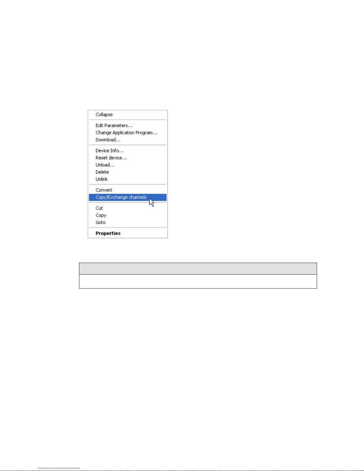
ABB i-bus KNX
Commissioning
58 2CDC 505 056 D0208 | SA/S
3.1.2.1 Procedure
• Import the current VD3 file into ETS3 and add a product and its current application program to the
project.
• Right-click on the product whose outputs you wish to copy or exchange and select Copy/Exchange
channels in the context menu
Then make the required settings in the Copy/Exchange channels dialog.
Please note
When the term “channels” is used in ETS, it means inputs and/or outputs. To make the language of ETS
generally valid for as many ABB i-bus® devices as possible, the word channels is used in this document.
Page 56

ABB i-bus KNX
Commissioning
SA/S | 2CDC 505 056 D0208 59
3.1.2.2 Copy/Exchange channels dialog
You can see general product information in the upper area of the window.
Below it you will find a selection window for the source channel so that you can mark it.
Beside it is the selection window for marking the destination channel(s).
Source channel
The source channel selection defines which parameter settings should be copied or exchanged. Only one
source channel can be selected at a time.
Page 57

ABB i-bus KNX
Commissioning
60 2CDC 505 056 D0208 | SA/S
Destination channels
By selecting the destination channel(s) you define which channel(s) are to assume the parameter settings
of the source channel.
• For the Exchange function, only one target output can be selected at a time.
• For the Copy function, var i ous dest inat ion cha nne ls can be select ed simult aneously. To do this, press
the Ctrl key and mark the required channels, e.g. channel B and H, with the mouse pointer.
With this button, you select all available destination channels, e.g. A…H.
Reset the destination channel selection with this button.
Copy
The following options can be selected before copy ing the par amet er settin gs:
• Keep group addresses in the destination chan nel un chan ged (if poss ible )
• Copy group addresses
• Delete group addresses in the destination cha nne l
With this button, you copy the settings of the source cha nnel into
the target channel(s).
Exchange
The following options can be selected before exchanging the parameter settings:
• Exchange without group addresses
• Exchange with group addresses
• Delete group addresses
With this button, you exchange the settings of the source channel with
those of the destination channel.
Confirm your selection with this button, and the window closes.
This button, closes the window without accepting the changes.
Page 58

ABB i-bus KNX
Commissioning
SA/S | 2CDC 505 056 D0208 61
3.2 Parameters
The Switch Actuator is parameterized using Engineering Tool Software (ETS), version ETS2 V1.3 or
higher.
In ETS2/ETS3 the application program can be found under ABB/Output/Binary output/Switch xf.
The following sections describe the parameters of the Switch Actuators by their parameter windows.
Parameter windows are structured dynamically so that further parameters may be enabled depending on
the settings and the function.
The default values of the parameters are underlined, e.g.:
Options: yes
no
Please note
This product manual describes all the current 2/4/8 and 12-fold Switch Actuators. These devices have
2/4/8 or 12 outputs respectively. However, as the functions for all outputs are identical, only the
functions of output A will be described.
Where information in the product manual refer s to all outputs, the description output A...X is used. 2-fold
corresponds to outputs A...B, 4-fold corresponds to outputs A...D, 8-fold corresponds to outputs A...H
and 12-fold corresponds to outputs A...L.
The variants with current detection feature an additional parameter page as well as additional
communication objects for this function.
Page 59

ABB i-bus KNX
Commissioning
62 2CDC 505 056 D0208 | SA/S
3.2.1 Parameter window General
Higher level parameters can be set in the General parameter window.
Transmission and switching delay
time after recovery of bus voltage [2…255s]
Options: 2…255
During the transmission and switching delay, telegrams are received only. The telegrams are not
processed, however, and the outputs remain unchanged. No telegrams are sent via the bus.
After the transmission and switching delay, telegrams are sent and the state of the outputs is set to
correspond with the parameterization or the communication object values.
If communication objects are read during the sending and switching delay, e.g. by a visualization system,
these read requests are stored, and a response is sent, after the sending and switching delay has been
completed.
An initialization time of about two seconds is included in the delay time. The initialization time is the time
that the processor requires to be ready to function.
How does the device react on bus voltage recovery?
After bus voltage recovery, the device always waits for the transmission delay time to elapse before
sending telegrams via the bus.
Page 60

ABB i-bus KNX
Commissioning
SA/S | 2CDC 505 056 D0208 63
Rate of telegrams
Options: not limited
1 Telegram / Second
2 Telegrams / Second
3 Telegrams / Second
5 Telegrams / Second
10 Telegrams / Second
20 Telegrams / Second
The load on the bus generated by the device can be limited by the telegram rate. This limit relates to all
telegrams sent by the device.
• x* Telegrams / Second: within a second, x telegrams are sent as quickly as possible via the bus.
Please note
The device counts the number of telegrams sent within a second. As soon as the maximum number of
sent telegrams is reached, no further telegra ms are sent via K NX until the end of the second. The
telegram counter is reset to zero, and sending is allowed again after the second has timed-out. The
current communication object value is always sent at the time of transmission.
Example
Maximum number of sent telegrams = 5,
20 telegrams are ready to send. The device immediately sends 5 telegrams. The next 5 telegrams are
sent after a maximum of 1 second. From this point, a further 5 telegrams are sent via KNX every
second.
x = 1, 2, 3, 5, 10 or 20
Send cyclical "In operation" telegram
[0...65,535s, 0 = inactive]
Options: 0…65,535
The communication object In Operation indicates that the device on the bus is working properly. This cyclic
telegram can be monitored by an external device.
Please note
After bus voltage recovery, the communication object sends its value after the set sending and
switching delay.
To keep the bus load to a minimum, the longest possible transmission time interval should be selected,
based on the application.
Page 61

ABB i-bus KNX
Commissioning
64 2CDC 505 056 D0208 | SA/S
Enable Safety Object for operating mode
"Switch Actuator"
Options: no
yes
• yes: Three further parameters appear:
Function Safety Priority 1
Function Safety Priority 2
Function Safety Priority 3
Options: inactive
enabled by object value “0”
enabled by object value “1”
Please note
The functions and setting options for parameters Function Safety Priority 2 and Function Safety
Priority 3 are the same as those for parameter Function Safety Priority 1.
In Switch Actuator operati ng m ode there ar e three Function Safety Priority x* parameters available. For
each priority, you can define your own trigger condition (enabling condition) here. With safety activation,
the relevant Safety Priority x* communication object becomes visible. These communication objects relate
to the entire device. However, every output can react differently to the receipt of a telegram. The reaction
of the output is parameterized in parameter window X: Safety of the respective output.
*x = 1, 2 or 3
• inactive: The Safety Priority x function is not used.
• enabled by object value "0": Safety activation is triggered if communication object Safety Priority x*
receives a telegram with the value 0. The following parameter appears.
• enabled by object value "1": Safety activation is triggered if communication object Safety Priority x
receives a telegram with the value 1 . The following parameter appears:
Page 62

ABB i-bus KNX
Commissioning
SA/S | 2CDC 505 056 D0208 65
Control period in seconds
[0…65,535s, 0 = inactive]
Options: 0…65,535
This parameter defines the monitoring period of the Safety Priority x function. If during this time
communication object Safety Priority x* receives a telegram with the triggering condition defined in
parameter Function Saf ety Priority x, it will be triggered. Should the communication object Safety Priority x*
receive a telegram that does not fulfill the trigger conditions, the control period is reset and restarted.
• 0: No monitoring is taking place. However, the Safety Priority x is triggered if communication object
Safety Priority x receives a telegram with the triggering condition as defined in parameter Function
Safety Priority x
*x = 1, 2 or 3
Please note
The monitoring period in the Switch Actuator should be at least twice as long as the cyclical
transmission time of the sensor, so that the absence of an individual signal, e.g. due to a high bus load,
does not immediately trigger an alarm.
Page 63

ABB i-bus KNX
Commissioning
66 2CDC 505 056 D0208 | SA/S
3.2.2 Parameter window A: General
Please note
This product manual describes all the current 2/4/8 and 12-fold Switch Actuators. These devices have
2/4/8 or 12 outputs respectively. However, as the functions for all outputs are identical, only the
functions of output A will be described.
All general settings for output A are undertaken in this parameter window.
Operating mode of output A
Options: Switch Actuator
Heating Actuator
This parameter defines the operating mode of the output. As the parameters and possible functions as well
as other parameter windows are different for each operating mode, we will describe them separately here
for each mode:
• Operating mode Switch Actuator, p. 67
• Operating mode Heating Actuator , from p. 119
Page 64
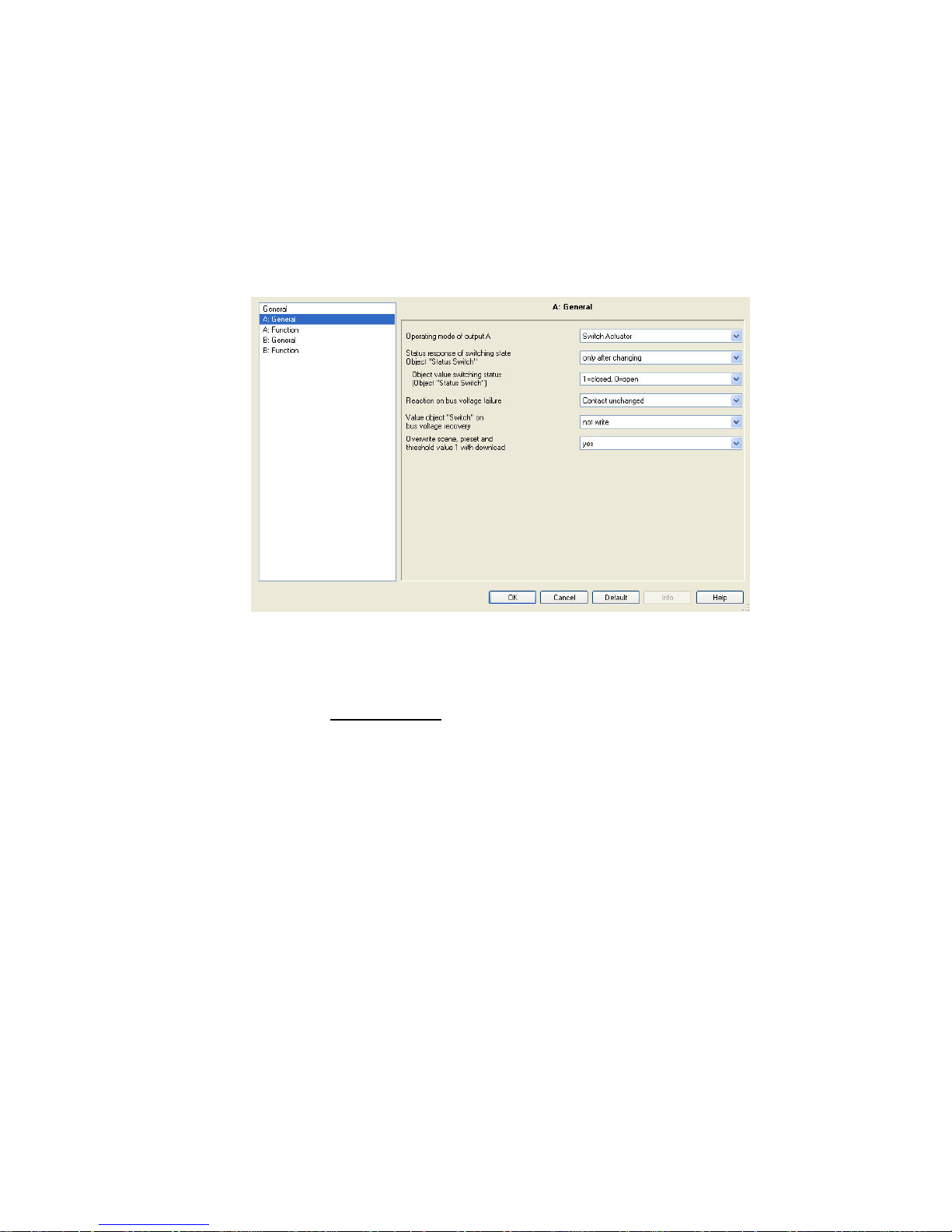
ABB i-bus KNX
Commissioning
SA/S | 2CDC 505 056 D0208 67
3.2.3 Operating mode Switch Actuator
The Switch Actuator operating mode is used for normal switching, e.g. of lighting. The output is controlled
via various logic, time and safety functions. The input signal for the function is received via communication
object Switch. The Switch Actuator carries out the function independently and controls the corresponding
relay.
The comprehensive range of additional functions available are described in this section.
Status response of switching state
Object "Status Switch"
Options: no
only after changing
always
This parameter can enable the communication object Status Switch. This contains the current switch state
i.e. contact position.
• no: The contact position is updated but the status is not actively sent via the bus.
• only after changing: if the contact position changes the status is actively sent via the bus by
communication object Status Switch.
Page 65

ABB i-bus KNX
Commissioning
68 2CDC 505 056 D0208 | SA/S
• always: The status of the contact position is always actively sent via the bus via communication object
Status Switch, even when a change in status has not occurred. Transmission is triggered as soon as
the communication objects Switch, Threshold input or Permanent ON receive a telegram. Even a
scene or a preset recall triggers transmission of the switch state. The status is also sent if logic objects
Logical connection 1 or Logical connection 2 receive a telegram. However, status is not repeated or
resent due to a safety change (forced operation, priority) and this applies to all types. This can have a
major effect on the bus load on a Switch Actuator with multiple outputs.
Please note
After parameterization changes or subsequently switching off the status object, the existing assignment
of group addresses to the Switch communication object is lost and needs to be re-allocated.
The status value to be sent is defined using the parameter Object value switching status (Object “Status
Switch”).
Please note
The contact position is determined by a sequence of priorities and logical connections – see Function
diagram, p. 161.
The contact position can only be correctly evaluated if the switching actions occur via KNX. The SA/S
cannot differentiate between manual switching and a cable break or device fault.
Object value switching status
(Object “Status Switch”)
Options: 1=closed, 0=open
0=closed, 1=open
• 1=closed, 0=open: In communication object Status Switch, the value 1 is written for a closed contact,
and the value 0 for an open contact.
• 0=closed, 1=open: In communication object Status Switch the value 0 is written for a closed contact,
and the value 1 for an open contact.
Reaction on bus voltage failure
Options: Contact open
Contact closed
Contact unchanged
The output can adopt a defined state on bus voltage failure with this parameter.
For further information see: Reac ti on on bus volta ge failure, recovery and download, p. 166
Page 66

ABB i-bus KNX
Commissioning
SA/S | 2CDC 505 056 D0208 69
Value object "Switch" on
bus voltage recovery
Options: not write
to write with 0
to write with 1
With this parameter, the output can be influenced after bus voltag e recov ery . As standar d t he
communication object Switch receives the value 0.
• not write: After bus voltage recovery, communication object Switch retains the value 0. The contact
position is not re-determined.
Please note
Before the very first download (device fresh from the factory), the value before bus voltage failure is not
defined. For this reason, the communication object Switch is written with 0 and the contact is open.
If opening of the contact at bus voltage recovery before the first download (installation phase) is not
desired, this can be prevented by temporarily removing the KNX voltage.
• to write with 0: The communication object Switch is written with a 0 on bus voltage recovery.
The contact position is redefined and set based on the set device parameterization.
• to write with 1: The communication object Switch is written with a 1 on bus voltage recovery.
The contact position is redefined and set based on the set device parameterization.
Please note
Provided that no manual sw itching act ion has occurre d, the communi cat ion obje ct Status Switch
indicates the correct status of the contact position independently of the value of communication object
Switch.
The Switch Actuator draws the energy for switching the contact from the bus. Depending on the type of
Switch Actuator, about 10 to 30 seconds is required after bus voltage is applied before sufficient energy
is available to switch all contacts simultaneously, see Technical data from p. 9
.
Depending on the set delay time in the parameter Transmission and switching delay after recovery of
bus voltage in the General parameter window, the individual outputs assume the desired contact
position only after this delay has elapsed. If a shorter delay time is set, the Switch Actuator will only
switch the first contact when sufficient energy is stored in the Switch Actuator to immediately bring all
outputs safely to the required position should another bus voltage failure oc cur.
Page 67

ABB i-bus KNX
Commissioning
70 2CDC 505 056 D0208 | SA/S
Overwrite scene, preset and
threshold value 1 with download
Options: no
yes
This parameter determines whether the preset and scene values and threshold value 1 of the output
modified via the bus are overwritten in the Switch Actuator by the values set in parameter windows
A: Scene, A: Preset or A: Threshold.
• yes: The values set in Parameter windows A: Scene, A: Preset or A: Threshold are transferred to the
Switch Actuator when a download occurs, overwriting the existing values. Reprogramming of these
values via the bus is still possible at any time.
• no: The values set in Parameter windows A: Scene, A: Preset or A: Threshold value are not
transferred to the Switch Actuator when a download occurs. The values can only be changed and set
via the bus.
For further information see: Parameter window A: Scene, p. 89 , Parameter window A: Preset, p. 86 and
Parameter window A: Threshold, p. 98
Page 68

ABB i-bus KNX
Commissioning
SA/S | 2CDC 505 056 D0208 71
3.2.3.1 Parameter window A: Function
In this parameter window you determine the response (reaction) of the output and can enable different
functions, which makes further parameter windows available.
Reaction of output A
Options: Normally closed contact
Normally open contact
This parameter determines the reaction of the output as a normally open or normally closed contact.
• Normally closed co ntact: An ON telegram (1) opens the contact and an OFF telegram (0) closes it.
• Normally open contact: An ON telegram (1) closes the contact and an OFF telegram (0) opens it.
Enable time functions "delay, staircase lighting, flashing"
Options: no
yes
• no: Parameter window A: Time is not enabled for output A.
• yes: Parameter window A: Time for output A, and communication object Disable time function, are
enabled.
Using this communication object, the Time function can be enabled (telegram with value 0) or disabled
(telegram with value 1) via the bus.
As long as the Time function is disabled, the output can be switched on and off only without delay via the
communication object Switch. The priorities as listed in Function diagram on p. 147 still remain valid.
Page 69

ABB i-bus KNX
Commissioning
72 2CDC 505 056 D0208 | SA/S
Please note
The Time function is only disabled when the ongoing Time function has ended.
While the output is disabled, the higher switching priorities, e.g. Safety functions, are undertaken.
Enabling the Time function enables the communication object Permanent ON. The output is switched
on via this communication object. It remains switched on until communication object Permanent ON
receives a telegram with the value 0.
Functions continue to operate in the background during the Permanent ON phase. The contact position
at the end of the Permanent ON phase results from the functions operating in the background.
With the selection yes a new parameter appears:
Value object "Disable time function"
after bus voltage recovery
Options: "1", disable time functions
"0", enable time functions
• "1", disable time functions: The Time function is disabled by a telegram with the value 1.
Please note
They can only be re-enabled via the communication object Disable time function.
• "0" enable time functions: The Time function is enabled by a telegram with the value 0.
Please note
Should the staircase light on the SA/S x.6.1.1, SA/S x.10.2.1 or SA/S x.16.2.1 be disabled while
the Time function is running, the time sequence stops and the light remains ON until switched off
by an OFF telegram.
On the SA/S x.16.6.1 the timing continues to the end. Only then is the Time function no longer
active.
Page 70

ABB i-bus KNX
Commissioning
SA/S | 2CDC 505 056 D0208 73
How does the staircase lighting react on bus voltage failure?
Reaction in the event of bus voltage failure is specified by the parameter Reaction on bus voltage
failure in parameter window A: General.
How does the staircase lighting react on bus voltage recovery?
Reaction on bus voltage recovery is defined by two conditions:
A By the communication object Disable time function. If staircase lighting is disabled after bus
voltage recovery, it can only be switched on or off via the communication object Switch.
B By parameterization of the communication object Switch. Whether the light is switched on or
off on bus voltage recovery depends on the settings of Switch.
Enable function "presets"
Options: no
yes
• no: Parameter window A: Preset is not enabled for output A.
• yes: Parameter window A: Preset is enabled for output A.
Enable function "scene (8 bit)"
Options: no
yes
• no: Parameter window A: Scene is not enabled for output A.
• yes: Parameter window A: Scene is enabled for output A.
Enable function "logic"
Options: no
yes
• no: Parameter window A: Logic is not enabled for output A.
• yes: Parameter window A: Logic is enabled for output A.
Page 71

ABB i-bus KNX
Commissioning
74 2CDC 505 056 D0208 | SA/S
Enable functions "priority and safety
operation"
Options: no
yes
• no: Parameter window A: Safety is not enabled for output A.
• yes: Parameter window A: Safety is enabled for output A. This parameter window is used for
parameterizing Safety Priorities 1, 2, 3 and Forced operation.
Enable function "threshold"
Options: no
yes
• no: Parameter window A: Threshold is not enabled for output A.
• yes: Parameter window A: Threshold is enabled for output A.
Enable function "current detection"
Options: no
yes
• no: Parameter window A: Current Detection is not enabled for output A.
• yes: Parameter window A: Current detection, and communication object Contact monitoring, are
enabled for output A.
Please note
These parameters and their functions are only visible for Switch Actuators with current detection. The
actuators with integrated current detection are recognizable by a number 6 as the third number of the
type designation, e.g. SA/S 2.16.6.1.
Page 72

ABB i-bus KNX
Commissioning
SA/S | 2CDC 505 056 D0208 75
Send status via object
"contact monitoring"
Options: no
only after changing
always
The send behavior of the communication object Contact monitoring can be set using this parame t er. The
Contact monitoring communication object displays contact faults. An error (value 1) is displayed as soon
as a current of about 30 mA (observe the tolerances) is detected on an open contact.
• no: The value of the communication object is always updated but not sent.
• always: The switch status is updated and always sent when there is a change of status or the contact
is to be opened and is not yet open. No value is sent when closing the contact. The reset status is
only sent when it is next opened.
• only after changing: A telegram is only sent if the value of communication object Contact m onitoring
changes. This can influence the bus load significantly, particularly for Switch Actuators with multiple
outputs.
Important
The contact position can only be correctly evaluated if the switching actions occur via KNX.
The SA/S cannot differentiate between manual switching and a cable break or device fault.
Evaluation of the contact monitoring occurs about two seconds after opening the contact.
Page 73

ABB i-bus KNX
Commissioning
76 2CDC 505 056 D0208 | SA/S
3.2.3.1.1 Parameter window A: Time
All settings for the Time function are undertaken in this parameter window: ON/OFF delay, Staircase
lighting function and Flashing.
This parameter window is visible if the Enable time fun ctio n parameter has been enabled in
Parameter window A: Function, p. 71
.
Explanations of the Time functions and sequences can be found in Planning and application, p. 141.
Please also refer to the Function diagram, p. 147, from which the switching and timing priorities originate.
Page 74

ABB i-bus KNX
Commissioning
SA/S | 2CDC 505 056 D0208 77
Time function
Options: Staircase lighting function
ON/OFF delay
Flashing
This parameter defines the type of Time function for each output.
• Staircase lighting function: The value that switches the staircase lightin g on and off can be
parameterized. The staircase lighting time starts when the function is switched on. It is switched off
immediately after the staircase lighting time ends.
Please note
Switch on means the closing of a normally open contact or opening of a normally closed contact.
The staircase lighting function can also be recalled via communication object Switch, Logical
Connection x (x = 1, 2) or via a light scene recall.
The staircase lighting function can be disabled by a telegram to the communication object Disable time
function.
Parameterization is undertaken in parameter window Parameter window A: Function, p. 71
, with the
parameter Value object "Disable time function" on bus voltage recovery.
• ON/OFF delay: The output can be switched on or off with a delay via this function.
• Flashing: The output starts to flash as soon as communication object Switch receives the
parameterized value. The flashing period can be adjusted via the duration set for ON or OFF. At the
start of the flashing period, the output is switched on with a normally open contact and off with a
normally closed contact. When communication object Switch receives a new value, the flashing period
will restart. Relay state is parameterizable after flashing. Flashing can be inverted when the output is
used as a normally closed contact. The communication object Status Switch indicat es the c urr ent
relay state during flashing.
Please note
The Flashing function can be disable d by a telegram to communi cat ion object Disable time function.
Parameterization is undertaken in parameter window Parameter window A: Function, p. 71
, with the
parameter Value object "Disable time function" on bus voltage recovery.
Page 75

ABB i-bus KNX
Commissioning
78 2CDC 505 056 D0208 | SA/S
The following parameters appear when Staircase lighting is selected:
Duration of staircase lighting
Minutes
Options: 0…5…1,000
Seconds
Options: 0…59
The staircase lighting time defines how long the staircase lighting is switched on after an ON
telegram. The input is made in minutes and seconds. The staircase lighting time may extend
depending on the value set in the parameter Warning before end of staircase lighting.
Extending staircase lighting by
multiple operation ("pumping up")
Options: no (not retriggerable)
yes (retriggerable)
up to max. 2 x staircase lighting time
up to max. 3 x staircase lighting time
up to max. 4 x staircase lighting time
up to max. 5 x staircase lighting time
If a further ON telegram is received during the staircase lighting time sequence, the remaining
staircase lighting time can be extended by a further period. This is possible by repeated operation
of the button (“pumping up“) until the maximum parameterized number of retriggering operations is
reached. The maximum time can be set to 1, 2, 3, 4 or 5 times the staircase lighting time.
Let's say the staircase lighting time has been extended by “pumping up” to the maximum time.
If some of the time has already timed out, the staircase lighti ng time can be re-extended to the
maximum time by “pumping up”.
However the parameterized maximum time may not be exceeded.
• no (not retriggerable): The receipt of an ON telegram is ignored. The staircase lighting time
continues without modification to completion.
• yes (retriggerable): New ON telegrams reset the staircase lighting time and starts to count
again. This process can be repeated as often as desired using this selection.
• up to max. 2/3/4/5 x staircase lighting time: New ON telegrams extend the staircase lighting
time by 2/3/4/5 times the staircase lighting time.
Page 76

ABB i-bus KNX
Commissioning
SA/S | 2CDC 505 056 D0208 79
Staircase lighting can be switched off
Options: ON with "1" and OFF with "0"
ON with "1" no action with "0"
ON with "0" or "1", switch OFF not possible
This parameter defines the telegram value used for switching the staircase lighting on and off
prematurely.
• ON with "0" or "1" switch OFF not possible: The staircase lighting function is switched on
independently of the value of the incoming telegram. Premature switch off is not possible.
Please note
After enabling the Time function via communication object Disable time function, the contact
position of the enabled output remains unchanged. The Time function is only triggered after the
next switching telegram. However this means that if set to the option ON with "1" no action with
"0", the output is simultaneously switched on when enabled. Switch off via the bus is thus not
possible. Only after e.g. the staircase lightin g funct ion is star t ed does the outp ut switc h off, after
the staircase lighting time has elapsed.
Warning before end of staircase lighting
Options: no
via object
via quick switching OFF/ON
via object and switching OFF/ON
Before the staircase lighting time elapse, the user can be informed of the imminent lighting switch of
by a warning. If the warning time is not 0, the staircase lighting time is extended by the warning
time. The warning time is not modified by “pumping up”.
• no: No warning is given, the staircase lighting switches off immediately after the staircase
lighting time elapses. If the staircase lighting is ended prematurely, e.g. by a switching
telegram, no warning is given.
Page 77

ABB i-bus KNX
Commissioning
80 2CDC 505 056 D0208 | SA/S
There are two types of warning:
1. The communication object warning stair lighting is set to the value 1 when the warning time starts, and
remains until it has elapsed. The communication object can be used, for example, to switch a warning
light.
2. Switching the output (briefly OFF and ON again).
Both options can be used together or separately. The time duration between the OFF and ON process is
about 1 second. If the warning time is not 0, the staircase lighting time is extended by the warning time.
Please note
When dealing with the warning time it is important to remember that the SA/S draws its switching
energy exclusively from the KNX. Furthermore, the SA/S collects enough energy before the first switch
to ensure that all outputs can safely go to the required position should the bus voltage fail. Under these
conditions, only a certain number of switching actions are possible per minute:
see Technical data, from p. 9
.
Warning time in sec. [0...65,535] add
to duration of staircase lighting
Options: 0…45…65,535
This parameter is visible if you have set a warning before the staircase lighting time ends.
The warning time must be entered in seconds. The staircase lighting time is extended by the
warning time. The warning is triggered at the start of the warning time.
The warning time is not modified by “pumping up”.
Duration of staircase lighting can be
changed by object
“Staircase lighting time”
Options: no
yes
• yes: A 2 byte Duration of stair lighting communication object is enabled. This can be used to change
the staircase lighting time via the bus. The value defines the staircase lighting time in seconds.
The staircase lighting function that has already started is completed first. A change is applied to the
staircase lighting time next time it is recalled.
• no: The staircase lighting time cannot be changed via the bus.
Please note
On bus voltage failure, the staircase lighting time changed via the bus is lost and must be reset.
Until a new value is set, the staircase lighting time set via ETS applies.
Page 78

ABB i-bus KNX
Commissioning
SA/S | 2CDC 505 056 D0208 81
How does the staircase lighting react on bus voltage failure?
Reaction in the event of bus voltage failure is specified by the parameter Reaction on bus voltage failure in
parameter window A: General.
How does the staircase lighting react on bus voltage recovery?
Reaction on bus voltage recovery is defined by two conditions.
A By the communication object Disable time function. If staircase lighting is disabled after bus voltage
recovery, it can only be switched on or off via the communication object Switch.
B By the parameterization of the communication object Switch. Whether the light is switched on or off
on bus voltage recovery depends on the settings of Switch.
Restart of staircase time after
end of permanent ON
Options: no
yes
• no: The lighting switches off if Permanent ON is ended.
• yes: The lighting remains on and the staircase lighting time restarts.
The function of Permanent ON is controlled via the communication object value Permanent ON. If the
communication object receives a telegram with the value 1, the output is switched on regardless of the
value of the communication object Switch and remains switched on until the communication object
Permanent ON has the value 0.
Please note
Permanent ON only switches ON and “masks” the other functions. This means that the other functions,
e.g. Staircase lighting time or “Pumping up”, continue to run in the background but do not initiate any
action. After Permanent ON ends, the contact position which would result without the permanent ON
function becomes active.
Page 79

ABB i-bus KNX
Commissioning
82 2CDC 505 056 D0208 | SA/S
The following parameters appear with ON/OFF delay:
The output can be switched on or off with a delay via this function. Explanations for ON/OFF delay can be
found at ON/OFF delay, p. 151
. You will also find a timing diagram as well as explanations on the effect of
various ON and OFF telegrams in combination with ON/OFF delay.
Delay for switching on: Min. [0…65,535]
Delay for switching on: Sec. [0…59]
Options: 0…65,535
0…59
Here you set the time by which an ON telegram is delayed after switch on.
Delay for switching OFF: Min. [0…65,535]
Delay for switching OFF: Sec.. [0…59]
Options: 0…65,535
0…59
Here, you set the amount of time by which switch OFF is delayed after a switch OFF telegram.
Page 80

ABB i-bus KNX
Commissioning
SA/S | 2CDC 505 056 D0208 83
The following parameters appear when Flashing is selected:
The output starts to flash as soon as communication object Switch receives the parameterized value.
The flashing period can be adjusted via the parameterized time duration for ON or OFF. At the start of the
flashing period, the output is switched on with a normally open contact and off with a normally closed
contact. When communication object Switch receives a new value, the flashing period will restart. The
relay state after flashing can be parameterized. Flashing can be inverted when the output is used as a
normally closed contact.
The communication object Status Switch indicates the current relay state duri ng flas hin g.
Please note
Only a certain number of switching actions are possible per minute and Switch Actuator. This means
that frequent switching may cause a switching delay, see Technical data, from p. 9. The same applies
directly after bus voltage recovery.
When the flashing function is selected, the service life of the switching contacts must be considered,
see Technical data, from p. 9
.
The Flashing function can be disabled by a teleg ram to the comm uni cat ion obje ct Disable time function.
The parameterization is undertaken in parameter window Parameter window A: Function, p. 71
, with the
parameter Value object "Disable time function" on bus voltage recovery.
Page 81
ABB i-bus KNX
Commissioning
84 2CDC 505 056 D0208 | SA/S
Flashing if object "Switching" is
Options: ON (1)
OFF (0)
always flashing, ON (1) or OFF (0)
Here you set the value of the communication object Switch at which the output flashes. Flashing is not
retriggerable.
• ON (1): Flashing starts when communication object Switch receives a telegram with the value 1.
A telegram with the value 0 ends flashing.
• OFF (0): Flashing starts when communication object Switch receives a telegram with the value 0.
A telegram with the value 1 ends flashing.
• always flashing, ON (1) or OFF (0): A telegram with the value 1 or 0 triggers flashing. Suspension of
flashing is not possible in this case.
Time for ON: Min. [0…65,535]
Time for ON: Sec. [0…59]
Options: 0…65,535
1…5…59
Time for ON defines how long the output is switched on during a flashing period. The smallest value is
1 second.
Please note
Only a certain number of switching actions are possible per minute and Switch Actuator. This means
that frequent switching may ca use a switch ing del ay , see Technical data, from p. 9. The same applies
directly after bus voltage recovery.
Time for OFF: Min. [0…65,535]
Time for OFF: Sec. [0…59]
Options: 0…65,535
1…5…59
The time for OFF defines how long the output is switched off during a flashing period. The smallest value
is 1 second.
Please note
Only a certain number of switching actions are possible per minute and Switch Actuator. This means
that frequent switching may cause a switching delay, see Technical data, from p. 9. The same applies
directly after bus voltage recovery.
Page 82

ABB i-bus KNX
Commissioning
SA/S | 2CDC 505 056 D0208 85
Number of ON impulses: [1...100]
Options: 1…5…100
This parameter defines the maximum number of pulses. This is useful to prevent flashing causing
unnecessary wear of the contacts.
Contact position after flashing
This parameter defines the state that the parameter should assume after flashing.
• ON: The output is switched on after flashing.
• OFF: The output is switched off after flashing.
• calculate present contact posit ion: The output assumes the contact position which it had before
flashing commenced.
For further information see: Function diagram, p. 147
Please note
Observe the contact life span and switching cycles per min ute.
Please note
Only a certain number of switching actions are possible per minute and Switch Actuator. This mea n s
that frequent switching may cause a switching delay, see Technical data, from p. 9. The same applies
directly after bus voltage recovery.
Page 83

ABB i-bus KNX
Commissioning
86 2CDC 505 056 D0208 | SA/S
3.2.3.1.2 Parameter window A: Preset
Preset settings can be made in this parameter window.
This parameter window is visible if Enable function "presets" has been enabled in
Parameter window A: Function, p. 71
.
What is a preset?
Presets are used to recall a parameterized switch value, e.g. in order to implement light scenes.
In addition, the output value that is currently set can be saved as a new preset value.
The preset values can be set (stored) via the bus. In parameter window A: General you define
whether the values set in ETS are transferred to the Switch Actuator with a download. This is how
the values saved in the actuator are overwritten.
Two presets are available per output. Preset 1 is recalled by a telegram with the value 1, Preset 2 is
recalled by a telegram with the value 0. Separate communication objects are available for recalling
and for saving/setting a preset.
Preset telegrams continue to be executed when the Staircase lighting function is set. The Staircase
lighting function is triggered by a preset recall (ON telegram).
Page 84

ABB i-bus KNX
Commissioning
SA/S | 2CDC 505 056 D0208 87
Reaction on preset 1 (telegr. value 0)
Options: no reaction
ON
OFF
restore old value before preset 2
restore parameterized value of preset 2
This parameter determines the contact position that the output assumes when preset 1 is recalled, i.e.,
communication object Call Preset 1/2 receives a telegram with the value 0.
The following functions can be selected as further selection options:
• no reaction: No switching action is undertaken with a preset recall. The preset is ignored. The preset
is also ignored on storage via the bus, i.e., no value is saved, the preset remains inactive.
• restore old value before preset 2: The current relay contact position is stored when preset 2 is first
recalled. This stored value (switch state) is retained until it is set again by the recall of preset 1.
The current contact position is stored again next time preset 2 is recalled.
Example
With preset 2, the lighting in a conference room is recalled for a presentation. When the presentation is
finished, the lighting is restored via preset 1 to the state it was in previously.
• restore parameterized value of preset 2: resets preset 2 to the parameterized value. This can be
advisable if preset 2 can be stored via the bus, see below.
Please note
With options restore old value before pr e set 2 or restore parameterized value of preset 2, saving the
preset concerned has no effect. The saved value is not recalled, but rather the parameterized function is
undertaken.
Page 85

ABB i-bus KNX
Commissioning
88 2CDC 505 056 D0208 | SA/S
Reaction on preset 2 (telegr. value 1)
Options: no reaction
ON
OFF
This parameter determines the contact position that the output assumes when preset 2 is recalled, i.e.,
communication object Rec all Preset 1/ 2 receives a telegram with the value 1.
At the same time, on the first call up of preset 2, the state of the output is saved so that the value before
preset 2 can be restored if the setting is changed according ly .
Preset can be set via the bus
Options: no
yes
This parameter enables the communication object Set preset 1/2. It is thus possible to store the current
contact position as the new preset value.
Telegram value 0 saves preset 1, whereas telegram value 1 saves preset 2.
If the option no reactio n, restore old value before preset 2 or restore parameterized value of preset 2 has
been selected in parameter Reaction on preset 1 (telegr. value 0), no new communication object value is
saved.
Using the parameter Overwrite scene, preset and threshold value 1 with download in parameter window
A: General, it is possible not to overwrite the scene values set via the bus during a download and thus to
protect them.
If a mains voltage failure occurs the stored preset values are lost. They are overwritten by the
parameterized default values.
Page 86

ABB i-bus KNX
Commissioning
SA/S | 2CDC 505 056 D0208 89
3.2.3.1.3 Parameter window A: Scene
All settings for the Scene function are undertaken in this parameter window.
This parameter window is visible if the parameter Enable function "scene" has been enabled in
Parameter window A: Function, p. 71
.
Using the parameter Overwrite scene, preset and threshold value 1 with download in parameter window
A: General, it is possible not to overwrite the scene values set via the bus during a download and thus to
protect them.
Output is assigned to
[Scene 1…64]
Options: no allocation
Scene 1
…
Scene 64
The Scene function manages up to 64 scenes using one single group addr es s. With this group addr e ss,
all slaves integrated into a scene are linked via a 1 byte communication object. The following information
is contained in a telegram:
• Scene number (1…64) and
• Telegram: Recall scene or stor e scene.
The output can be integrated in up to five scenes. So for example, the output can be switched on
by a scene in the morning and switched off in the evening, or it can be integrated into light scenes.
Page 87

ABB i-bus KNX
Commissioning
90 2CDC 505 056 D0208 | SA/S
Standard value
Options: ON
OFF
By storing a scene, the user has the opportunity to change the parameterized value stored in ETS. After a
bus voltage failure, the value saved via KNX is retained.
Please note
When a scene is recalled:
- the Time func tion is restarted.
- the logical connections are re-evaluated.
For further information see: Communication objects, Output A, p. 111, Scene function, p. 156 and
Code table, 8 bit scene p. 171
Page 88

ABB i-bus KNX
Commissioning
SA/S | 2CDC 505 056 D0208 91
3.2.3.1.4 Parameter window A: Logic
All settings for the Logic function are undertaken in this parameter window.
This parameter window is visible if Enable function "logic" has been enabled in
Parameter window A: Function, p. 71
.
The Logic function provides up to two logic objects for each output, which can be logically connected via
the communication object Switch.
The logic is always re-calculated when an object value is received. First, the communication object Logical
connection 1 is evaluated with communication object Switch. The result is then logically linked with
communication object Lo gical conn ect ion 2.
Explanations of the Logic function can be found in Logic function, p. 153
. Please also observe the
Function diagram, p. 147, where the priorities become evident.
Logical Connection 1
Options: disable
enable
These parameters enable the communication object Logical connection 1.
• enable: The following parameters appear:
Page 89

ABB i-bus KNX
Commissioning
92 2CDC 505 056 D0208 | SA/S
Function of object "Logical Connection 1"
Options: AND
OR
XOR
GATE
The logical function of the communication obj ect Log ica l Connect ion 1 is determined with the switch
telegram.
All three standard operations (AND, OR, XOR) are possible. In addition, the GATE operation can be used
to inhibit switch commands.
For further information see: Logic func ti on, p. 153
Result is inverted
Options: no
yes
• yes: The result of the logical connection can be inverted.
• no: There is no inversion.
Object value "Logical connection 1"
after bus voltage recovery
Options: 1
0
This parameter defines the value allocated to the communication object Logical connection 1 on bus
voltage recovery.
Please note
The values of communication objects Logica l conn ect ion 1/2 are stored on bus voltage failure.
The values are set again on bus voltage recovery
On reset via the bus, the values of communication objects Logical Connection 1/2 remain uncha nged .
If GATE is selected with the parameter Function of logical connection, a further parameter appears:
Page 90

ABB i-bus KNX
Commissioning
SA/S | 2CDC 505 056 D0208 93
Gate disabled, if Object value "Logical
Connection 1" is
Options: 1
0
This parameter defines the value at which communication object Logical Connection 1 disables the
GATE.
While it is disabled, telegrams received on communi cati on object Switch are ignored. As long as
GATE is active, the last value sent to the GATE input remains on the output's logic gate.
When disabled, the value that was on the output beforehand remains.
After the GATE is enabled, this value will be retained until a new value is received.
For further information see: Function diagram, p. 147
The GATE is deactivated on bus voltage failure and remains so on bus voltage recovery.
Logical Connection 2
The same programming options exist as those for parameter Logical Connection 1.
Page 91
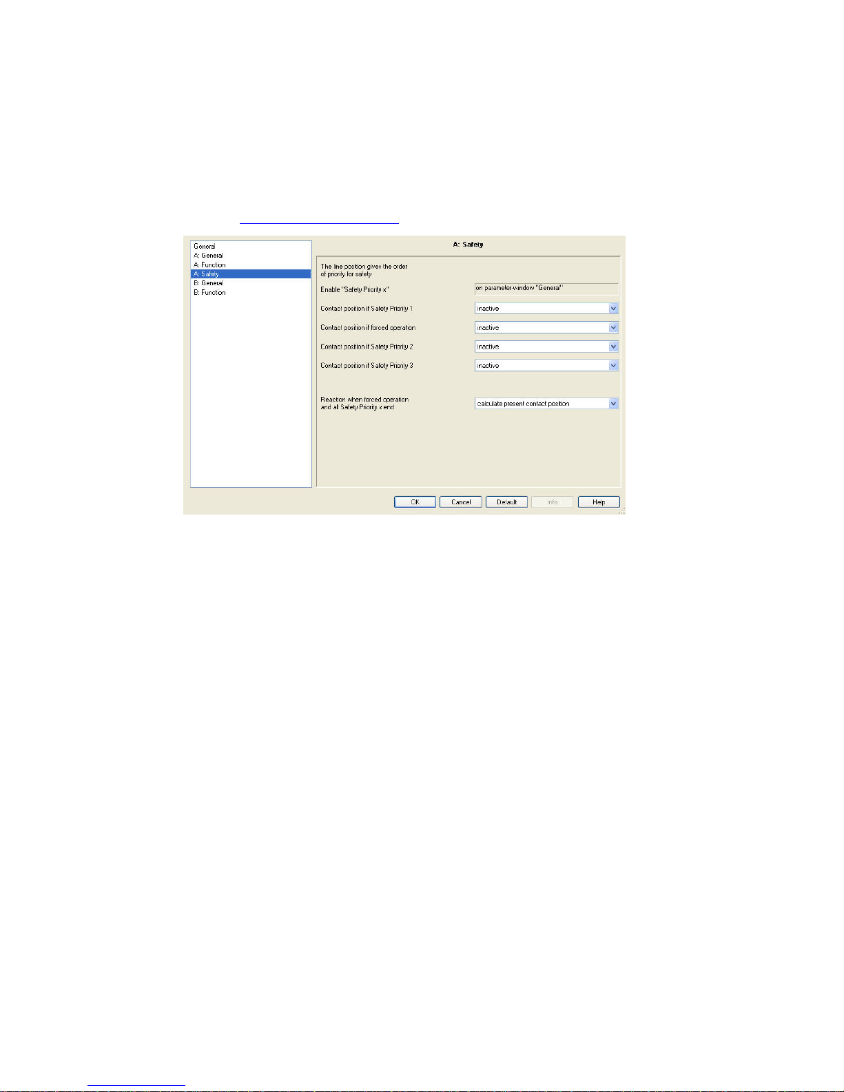
ABB i-bus KNX
Commissioning
94 2CDC 505 056 D0208 | SA/S
3.2.3.1.5 Parameter window A: Safety
All settings for the Safety function are undertaken in this parameter window.
This parameter window is visible if the parameter Enable functions "priority and safety operation" has been
enabled in Parameter window A: Function, p. 71
The forced operation (a 1 or 2 bit communication object per output) or safety priority (three independent
1 bit communication objects per Switch Actuator) sets the output in a defined state which can no longer be
changed as long as forced operation or safety priority is active. The parameterized reaction on bus voltage
failure and recovery has a higher priority.
Enabling of the three communication objects Safety Priority x (x = 1, 2, 3) is undertaken in the General
parameter window. Monitoring time and the telegram value to be monitored are set in this window.
If a telegram is not received within this monitoring time, the output will assume the safety position.
This is determined in parameter window A: Safety, descri be d below.
In contrast to the three safety priorities, each output has a communication object Forced operation.
Forced operation can be activated or deactivated via a 1 or 2 bit communication object. Using the 2 bit
communication object, the output state is defined directly via the value.
The contact position after the safety function ends can be set using the parameter Reaction when forced
operation and all Safety Priority x end.
Page 92

ABB i-bus KNX
Commissioning
SA/S | 2CDC 505 056 D0208 95
If multiple demands occur, the priority is defined as follows in accordance with the sequence in parameter
window A: Safety:
• Safety Priority 1 (highest priority)
• Forced operation
• Safety Priority 2
• Safety Priority 3 (lowest priority)
With the option inactive, Safety Priority x or Forced operation and the associated communication object
are not considered and are omitted from the priority sequence.
Contact position if Safety Priority 1
Options: unchanged
inactive
ON
OFF
This parameter determines the contact position of the output if the safety condition Safety Priority 1
(setting undertaken in parameter window Parameter window General, p. 62
) has been met.
The 1 bit communication object Safety Priority 1 is used as a master for the safety position. The contact
positions ON, OFF and unchanged are available.
• inactive: The state of communication object Saf ety Priority 1 has no effect on the output.
Contact position if forced operation
Options: inactive
unchanged via 1 bit object
on, via 1 bit object
off, via 1 bit object
switch position via 2 bit object
Forced operation relates to the 1 or 2 bit Forced operation communication object available on every
output.
• inactive: The state of the communication object Forced operation has no effect on the output.
• unchanged (via 1 bit object), on (via 1 bit object) and off (via 1 bit object): The 1 bit communication
object Forced operation determines the contact position of the output during forced operation.
• Switch position via 2 bit object: The 2 bit Forced operation communication object is enabled. The
value of the telegram sent via the 2 bit object determines the contact position, see the following table:
Page 93

ABB i-bus KNX
Commissioning
96 2CDC 505 056 D0208 | SA/S
Value Bit 1 Bit 0 State Description
0 0 0 Enabled If the communication object Forced operation receive s a t elegram with
the value 0 (binary 00) or 1 (binary 01), the output is enabled and can be
actuated via different communication objects.
1 0 1 Enabled
2 1 0 Forced
OFF
If the comm unication object Forced operation receives a telegram with
the value 2 (binary 10), the output of the Switch Actuator is switched off
and remains disabled until forced operation is switched off again.
Actuation via another communication object is not possible as long as
forced o peration is activated.
The state of the output at the end of forced operation can be
parameterized.
3 1 1 Forced ON If t he communication object Forced operation receives a telegram with
the value 3 (binary 11), the output of t he Switch Actuator is switched on
and remains disabled until forced operation is switched off again.
Actuation via another communication object is not possible as long as
forced o peration is activated.
The state of the output at the end of forced operation c an be
parameterized.
Object value "Forced positioning"
on bus voltage recovery
This parameter is only visible if forced operation is activated.
Depending on whether the forced operation object is a 1 bit or 2 bit communication object, there are
two different parameterization possibilities available:
1 bit communication object:
Options: inactive
active
• inactive: Forced operation is switched off, and the output behaves in the same way as with
parameter Reaction when forced operation and all safety Priority x end.
• active: Forced operation is active again after bus voltage recovery. The contact position of the
output is determined by the parameterization of Contact position if forced operation.
Page 94

ABB i-bus KNX
Commissioning
SA/S | 2CDC 505 056 D0208 97
2 bit communication object:
Options: "0" inactive
"2" OFF
"3" ON
• "0" inactive: Forced operation is switched off and the output behaves in the same way as with
parameter Reaction when forced operation and all safety Priority x end.
• "2" OFF: The communication object Forced operation is written with the value 2 and the output
is switched off.
• "3" ON: The communication object Forced operatio n is written with the value 3 and the output
is switched on.
Contact position if Safety Priority 2
Contact position if Safety Priority 3
The same setting options exist as those for parameter Contact position if Safety Priority 1.
Reaction when forced operation
and all Safety Priority x end
Options: calculate present contact position
ON
OFF
unchanged
This parameter is only visible if forced operation or a Safety Priority x (x = 1, 2 or 3) function is activated.
The contact position of the relay at the end of forced operation and safety priorities is defined here.
• calculate present contact posit ion: After forced operation has ended, the switch value is recalculated
and immediately initiated, i.e., the output continues to operate normally in the background during
forced operation, the output is not changed and is only set after safety priorities end.
• unchanged: The contact position is retained during forced operation or safety priority. The contact
position only changes when a new calculated switch value is received.
Page 95

ABB i-bus KNX
Commissioning
98 2CDC 505 056 D0208 | SA/S
3.2.3.1.6 Parameter window A: Threshold
All settings for the Threshold function are undertaken in this parameter window.
This parameter window is visible if the Enable function threshold parameter has been enabled in
Parameter window A: Function, p. 71
.
The threshold function facilitates the evaluation of a 1 or 2 byte communication object, Threshold input.
A switching action can be triggered as soon as the value of the communication object undershoots or
overshoots a threshold value. Two independent threshold values are available. Threshold 1 can be
modified via the bus.
For further information see: Thr e shol d f uncti on, p. 159
When the threshold function is active, the Switch Actuator continues to receive switching telegrams.
In this way, the contact position determi ned by the threshol d f unct ion can be change d,
see Function diagram, p. 147
. The threshold function generates a switching telegram as soon as a new
threshold telegram is received and a new switching condition exists simultaneously due to undershoot or
overshoot of the switching criterion.
Data type of object "Threshold input"
Options: 1 byte [0…255]
2 byte [0...65,535]
The data type for the threshold input received via the communication object Threshold input can be
determined here.
You can choose between a 1 byte integer value or a 2 byte counter value.
Page 96

ABB i-bus KNX
Commissioning
SA/S | 2CDC 505 056 D0208 99
Change Threshold 1 over bus
Options: no
yes
This parameter defines whether threshold value 1 can or cannot be changed via the bus.
• yes: Communication object Threshold value 1 can be changed via the bus. This can be a 1 or 2 byte
communication object depending on the parameterization of the threshold value input.
• no: The communication object Threshold value 1 cannot be changed via the bus.
With the parameter Overwrite scene, preset and threshold value 1 with download in parameter window
A: General, it is possible during a download to not overwrite the threshold values set via the bus and thus
to protect them.
Threshold value 1 [0...255]
The value range is dependent on the selection made in the parameter Data type of object "Threshold
input".
1 byte [0…255]:
Options: 0…80…255
2 byte [0…65,535]:
Options: 0…20,000…65,535
Threshold value 2 [0...255]
The value range is dependent on the selection made in the parameter Data type of object "Threshold
input".
1 byte [0…255]:
Options: 0…160…255
2 byte [0…65,535]:
Options: 0…40,000…65,535
Threshold values define hysteresis
Options: no
yes
This parameter defines whether Threshold values 1 and 2 should be interpreted as hysteresis limits.
The hysteresis can reduce continuous threshold value messages if the input value fluctuates around one
of the threshold values.
For further information see: Threshold function, p. 159
With option yes, the following parameters appear:
Page 97

ABB i-bus KNX
Commissioning
100 2CDC 505 056 D0208 | SA/S
Behaviour
Falling below lower threshold
Exceeding upper threshold
Options: no reaction
ON
OFF
This parameter determines the contact position of the output based on the value of communication
object Threshold input if this value exceeds or falls below the upper or lower threshold respectively.
A reaction only occurs if the communication object value was previously smaller or larger than
Threshold 1 or Threshold 2.
For further information see: Thre shol d f unc ti on, p. 159
With option no, the following parameters appear:
Object value < lower threshold
Lower thrsh. <= object <= upper thrsh.
Object value > lower threshold
Options: unchanged
ON
OFF
This parameter determines the contact position of the output (ON, OFF, unchanged) based on the
threshold (communication object) value.
Object "threshold input" value
on bus voltage recovery [0...255]
Object "threshold input" value
on bus voltage recovery [0...65,535]
The value range is dependent on the selection made in the parameter Data type of object "Threshold
input".
1 byte [0…255]:
Options: 0…255
2 byte [0…65,535]:
Options: 0…65,535
This parameter determines the value of communication object Threshold input after bus voltage recovery.
Threshold value evaluation is carried out after bus voltage recovery using the threshold parameterized
here, whereby the last St atu s Thr es hold value detected in operation is used for comparison. Should no
Status Threshold value exist before bus voltage failure, the factory-set status (hysteresis limit undershoot)
is assumed.
Page 98

ABB i-bus KNX
Commissioning
SA/S | 2CDC 505 056 D0208 101
3.2.3.1.7 Parameter window A: Current Detect ion
All settings for the Current Detection function are undertaken in this parameter window.
This parameter window is visible if the Enable function "current detection" parameter has been enabled in
Parameter window A: Function, p. 71
.
Please note
The current detection function and associated parameter window is only visible on Switch Actuators with
current detection (SA/S x.16.6.1). It offers the same functionality in both Switch Actuator and Heating
Actuator modes.
The settings in parameter window A: Current Detection determine if and how the load current of the output
is evaluated. Activating current detection enables the communication object Current Value.
Communication object Current Value transfers the detected current value as a mA value via KNX.
The current value is a pure sine wave normalized to an RMS value.
For further information see: Current detection specifications, p. 44 and Current detection, p. 141
Page 99

ABB i-bus KNX
Commissioning
102 2CDC 505 056 D0208 | SA/S
Datapoint type object "Current Value"
[0...65,535 in mA]
Options: 2 byte counter (DTP 7.012)
4 byte float (DTP 14.019)
This parameter determines the data type (datapoint, DTP) of the communication object Current Value.
A 2 byte counter (EIS 10, DPT 7.012, 1 mA per digit) or a 4 byte float value (EIS 9, DTP 14.019) can be
selected.
Please note
The current detection range is designed for currents between 20 mA and 20 A.
Send current value, transmission time
[0…65,535s; 0 = not send]
Options: 0
1…65,535
This parameter determines if and at which intervals the present current value is sent via communication
object Current Value. The cycle time must be entered in seconds.
• 0: No current values are sent cyclically via the bus. The present current values are however
continuously available in the output's Current Value communication object, and can be read out.
Send current value on change of value
Options: no
25/50/100/200/500 mA
1/2/5 A
This parameter determines that on a load change the current value is sent via the bus via the Current
Value communication object. A current value is always sent via the bus if the current change is greater
than the current value set in this parameter. The current value sent via the bus applies as a new reference
value.
• no: No current value is sent.
The smaller the current value set, the more precisely the sent value will correspond with the actual value.
Highly fluctuating current values may result in a high bus load.
For further information see: Current detection specifications, p. 44
Page 100

ABB i-bus KNX
Commissioning
SA/S | 2CDC 505 056 D0208 103
If the parameter Send current value, transmission time [0...65,535s, 0 = not send] is also activate d,
the counter is reset and restarted after sending the current value.
Please note
If for example, a current change of 1 A has been selected, a current value is only sent if the load current
exceeds 1 A when starting, for example, from 0 A. This means that no current value is sent (displayed)
when a current of 0.9 A is flowing.
The other way around, a current value can be displayed (sent) even though no current is flowing.
Starting from 1.5 A the current is reduced to 0 A. A current value of 0.5 A is sent via the bus. Since no
further 1 A current change can occur for a current value of 0, no new value is sent. The last value sent
and displayed is 0.5 A.
These inaccuracies can be prevented by additional activation of the parameter Send current value,
transmission time [0...65,535s, 0 = not send] or if a sufficiently small current change has been selected.
 Loading...