

ABB i-bus SA/S 2.16.2.1, i-bus SA/S 4.6.1.1, i-bus SA/S 2.16.6.1, i-bus SA/S 2.10.2.1, i-bus SA/S 4.10.2.1 Product Manual
...
ABB i-bus® KNX
SA/S Switch Actuators
Product Manual

ABB i-bus KNX
General
SA/S | 2CDC 505 056 D0208 5
1 General
KNX systems provide an attractive solution that meets the most demanding residential, commercial and
public buildings requirements. H igh liv ing stan dard s, com fort and safety can be easi ly comb ined w ith cos teffectiveness and environmental awareness using KNX bus systems from ABB. KNX products cover the
entire range of buildings applications, from illumination and blind control to heating, ventilation, energy
management, security and surveillance. These requireme nts can be met cos t-effectively with minimal
planning and installation effort using the ABB KNX. Furthermore, flexible room usage and continuous
adaptation to changing requirements are simple to implement. SA/S Switch Actuators fulfill individual
requirements in industrial, commercial and public buildings as well as in the private sector for controlling
switchable loads, e.g.:
• Illumination
• Heating control
• Signaling equipment
Certain types of Switch Actuator can also detect and monitor load current via a threshold value function.
Based on the load current detected, responses can be triggered via KNX and the load can be switched off
directly or switched via KNX.
1.1 Using the product manual
This manual provides you with detailed technical information on the ABB i-bus® SA/S Switch Actuator
range, its installation and programming.
Application of the device is explained using examples.
This manual is subdivided into the following sections:
Section 1 General
Section 2 Device technology
Section 3 Commissioning
Section 4 Planning and application
Section A Appendix

ABB i-bus KNX
General
6 2CDC 505 056 D0208 | SA/S
1.1.1 Structure of the product manual
All parameters are described in section 3.
Please note
This product manual describes all the current 2/4/8 and 12-fold Switch Actuators. However, as the
functions for all outputs are identical, only the functions of output A will be described.
Where information in the product manual refers to all outputs, the description output A...X is used. 2-fold
corresponds to outputs A...B, 4-fold corresponds to outputs A...D, 8-fold corresponds to outputs A...H
and 12-fold corresponds to outputs A...L.
Variants with current detection feature an additional parameter page as well as additional
communication objects for this function.
1.1.2 Notes
Notes and safety instructions are represented as follows in this product manual:
Please note
Tips for usage and operation
Example
Application examples, installation examples, programming examples
Important
These safety instructions are used as soon as there is danger of a malfunction without risk of damage
or injury.
Caution
These safety instructions are used if there is a danger of damage with inappropriate use.
Danger
These safety instructions are used if there is a danger to life and limb with inappropriate use.
Danger
These safety instructions are used if there is an extreme danger to life with inappropriate use.

ABB i-bus KNX
General
SA/S | 2CDC 505 056 D0208 7
1.2 Product and functional overview
SA/S
12.16.6.1
ABB i-bus® KNX SA/S Switch Actuators are modular installation devices with module widths of
2/4/8/12 units in ProM design for installation in a distribution board.
Connection to the ABB i-bus® is established via a bus connection terminal on the front.
The Switch Actuators require no auxiliary voltage.
The assignment of the physical address as well as the parameterization is carried out with
Engineering Tool Software (ETS), version ETS2 V1.3a or higher. If using ETS3 or ETS4 you
will need to import the corresponding application program.
Please note
The illustrations of the parameter windows in this manual correspond to the ETS3 parameter
windows. The user program is optimized for ETS3.
In ETS2 the parameter page for any parameter being used may split automatically.
The Switch Actuators can switch 2 to 12 independent electrical AC or three-phase loads via
KNX with floating contacts. With SA/S x.16.6.1 types it is possible to detect the load current for
each output. The outputs of the 6 A, 10 A, 16 A and 16/20 A Switch Actuators can be switched
on and off manually.
Switch Actuators SA/S x.16.6.1 and SA/S 12.16.5.1, which have the highest switching capacity
(C-load), are particularly well-suited for switching loads with high peak inrush currents, e.g.
lighting equipment with compensation capacitors or fluorescent lamp loads (AX) to EN 60 669.
The following functions can be set individually for each output:
• Time and ON/OFF delay functions
• Staircase lighting function with warning and modifiable staircase lighting time
• Recall of scenes/presets via 8/1 bit command s
• Logical functions AND, OR, XOR, GATE function
• Status messages
• Forced operation and safety functions
• Response to threshold values
• Control of electro-thermal valve drives
• Selection of the default state on bus voltage failure and recovery
• Output inversion
SA/S
8.16.6.1
SA/S
4.16.2.1
SA/S
2.10.2.1
SA/S
8.6.2.1
SA/S
8.6.1.1
SA/S
4.6.1.1
ABB i-bus KNX
General
8 2CDC 505 056 D0208 | SA/S
On Switch Actuators with current detection, SA/S x.16.6.1, each output also features the lo ad current
detection function with parameterizable response to two current threshold values. The current value can
be sent via the bus. Individual outputs in the Switch Actuators can be copied or exchanged to minimize
programming work.
The SA/S x.16.6.1 and SA/S x.16.5.1 are suitable for rated currents up to 20 A and have C-load switching
capacity.
In the following table you will find an overview of the ABB i-bus
®
Switch Actuators and their type
designations:
– SA/S 2.6.2.1 SA/S 2.10.2.1 SA/S 2.16.2.1 SA/S 2.16.5.1 SA/S 2.16.6.1
SA/S 4.6.1.1 SA/S 4.6.2.1 SA/S 4.10.2.1 SA/S 4.16.2.1 SA/S 4.16.5.1 SA/S 4.16.6.1
SA/S 8.6.1.1
SA/S 8.6.2.1
SA/S 8.10.2.1
SA/S 8.16.2.1
SA/S 8.16.5.1
SA/S 8.16.6.1
SA/S 12.6.1.1 SA/S 12.6.2.1 SA/S 12.10.2.1 SA/S 12.16.2.1 SA/S 12.16.5.1 SA/S 12.16.6.1
Please note
The codes represent the following:
SA/S x.y.z.w
x = number of outputs (2, 4, 8 or 12)
y = rated current in Amperes (6, 10, 16)
z = load type specification:
1 = type with no manual operation
2 = type with manual operation
5 = type with higher switch capacity, C-load (200 µF)
6 = type with higher C-load switching capacity and current detection
w = version number
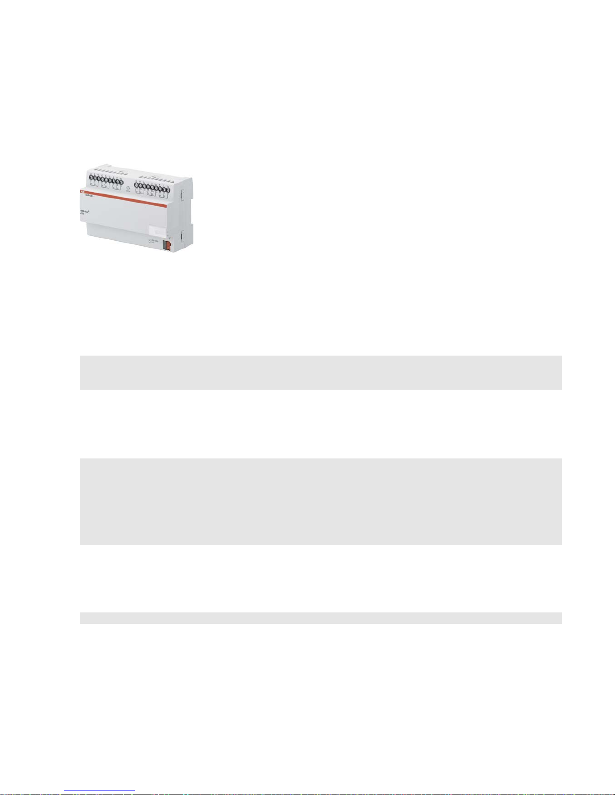
ABB i-bus KNX
Device technology
SA/S | 2CDC 505 056 D0208 9
2 Device technology
2.1 Switch Actuators SA/S x.6.1.1, 6 A, MDRC
SA/S
12.6.1.1
Switch Actuators SA/S
x.6.1.1 6 A are
modular installation devices in Pro
M
design for installation in the distribution
board. They are suitable for switching
resistive, inductive and capacit iv e loads.
The actuators can
switch up to
12
independent electrical loads via
floating contacts. The outputs are
connected using screw terminals in
groups of two
contacts for SA/S 8.6.1.1
and SA/S
12.6.1.1. SA/S 4.6.1.1 has one
terminal per output for power feed. Each
output is contr
olled separately via KNX,
regardless of the variant.
The device does not require an
additional power supply and is ready for
immediate use after the bus voltage
has been applied. The Switch Actuator
is parameterized via ETS. Connection
to KNX is implemented using the bus
connection terminal on the front.
2.1.1 Technical data
Supply
KNX bus voltage 21…32 V DC
Current consumption, bus < 12 mA
Power consumption
Maximum 250 mW
Rated output value
SA/S type 4.6.1.1 8.6.1.1 12.6.1.1
Current detection no no no
N
umber (floating contacts 2/group) 4 *) 8 12
U
n
rated voltage 250/440 V AC (50/60 Hz)
I
n
rated current (per output) 6 A 6 A 6 A
L
eakage loss per device at max. load 1.5 W 2.0 W 2.5 W
Output switching current
AC3
1)
operation (cos ϕ = 0.45)
To EN 60 947-4-1
6 A/230 V AC
AC3
1)
operation (cos ϕ = 0.8)
To EN 60 947-4-1
6 A/230 V AC
Fluorescent lighting load to EN 60 669-1 6 A/250 V AC (35 µF)2)
Minimum switching ca p acity 20 mA/5 V AC
10 mA/12 V AC
7 mA/24 V AC
Output service life
Mechanical service lif e
> 107
Electrical endurance
To IEC 60 947-4-1
A
C1
1)
(240 V/cos ϕ = 0.8)
> 10
5
AC31) (240 V/cos ϕ = 0.45)
> 1.5 x 10⁴
AC5a1) (240 V/cos ϕ = 0.45)
> 1.5 x 10⁴
*) Each output has one terminal for power feed.
2CDC 071 033 S0012

ABB i-bus KNX
Device technology
10 2CDC 505 056 D0208 | SA/S
Output switching times 3)
Maximum output relay position change per
minute if all relays are switched simultane o usly.
The position changes should be distributed
equally within the minute.
4.6.1.1 8.6.1.1 12.6.1.1
60 30 20
Maximum output relay position change per
minute if only one relay is swit ched.
240 240 240
Connections
KNX
Loa
d circuits
Tightening torque
Operating and display elements
Programming button/LED
Degree of protection
IP 20
Protection class
II
Isolation category
Overvoltage category
Pol
lution degree
Via bus connection terminals,
0.8 mm Ø, solid
Universal head screw terminal (PZ 1)
0.2… 4 mm2 fine stranded, 2 x 0.2…2.5 mm2
0.2… 6 mm2 solid, 2 x 0.2…4 mm
2
max. 0.6 Nm
For assignment of physical address To EN 60
529
To EN 61 140
III to EN 60 664-1
2 to EN 60 664-1
KNX safety extra low voltage
SELV 24 V DC
Temperature range
Operation
Storage
Transport
- 5 °C…+45 °C
-25 °C…+55 °C
-25 °C…+70 °C
Ambient conditions
Maximum a ir humidity 95 %, no condensation allowed
Design
Modular installation device (MDRC) Modular installation device, ProM
SA/S t
ype 4.6.1.1 8.6.1.1 12.6.1.1
Di
mensions 90 x W x 64.5 mm (H x W x D)
Widt
h W in mm 72 108 144
Mou
nting width in units (18 mm modules) 4 6 8
Mounting depth in mm 64.5 64.5 64.5
Weight
in kg
0.13 0.24 0.3
Mounting
On 35 mm mounting rail
To EN 60 715
Mounting position
As required
Housing/color
Plastic housing, gray
Approvals
KNX to EN 50 090 -1, -2 Certification
CE mark
in accordance with the EMC guideline and
low voltage guideline
1)
Further information concerning electrical endurance to IEC 60 947-4-1 can be found at: AC1, AC3, AX, C-load specifications, p. 43
2)
The maximum inrush current peak may not be exceeded.
3)
The specifications apply only after the bus voltage has been applied to the device for at least 30 seconds. Typical relay delay is approx. 20 ms.

ABB i-bus KNX
Device technology
SA/S | 2CDC 505 056 D0208 11
2.1.2 Lamp output load at 230 V AC
Lamps
Incande s cent lamp load 1,200 W
Fluorescent lamps T5/T8
Uncorrected
Parallel compensated
DUO circuit
800 W
300 W
350 W
Low-voltage halogen lamps
Inductive transform e r
Electronic transfor mer
Halogen lamps 230 V
800 W
1,000 W
1,000 W
Dulux lamp
Uncorrected
Parallel compensated
800 W
800 W
Mercury-vapor lamp
Uncorrected
Parallel compensated
1,000 W
800 W
Switching capacity (switchi ng conta c t )
Maximum peak inrush current Ip (150 µs)
Maximum peak inrush current I
p
(250 µs)
Maximum peak inrush current I
p
(600 µs)
200 A
160 A
100 A
Number of electronic ballasts (T5/T8, single
element)1)
18 W (ABB EVG 1 x 18 SF)
24 W (ABB EVG-T5 1 x 24 CY)
36 W (ABB EVG 1 x 36 CF)
58 W (ABB EVG 1 x 58 CF)
80 W (Helvar EL 1 x 80 SC)
10
10
7
5
3
1)
For multiple element lamps or other types, the number of electronic ballas ts mu s t be deter mined usi ng the peak inrush current of the electronic
ballasts, see Ballast calculation, p. 42
Device type Application program Maximum number of
communication objects
Maximum number of
group addresses
Maximum number of
associations
SA/S 4.6.1.1 Switch 4f 6A/…* 64 254 254
SA/S 8.6.1.1 Switch 8f 6A/…* 124 254 254
SA/S 12.6.1.1 Switch 12f 6A/…* 184 254 254
* … = current version number of the application program
Please note
ETS and the current version of the device application program are required for programming.
The current application program is available for download at www.abb.com/knx. After import into ETS
it can be found under ABB/Out put/Binary output xf 6A/…* (x = 4, 8 or 12).
The device does not support the locking function of a KNX device in ETS. If you inhibit access to all of
the project devices by using a BCU code, it has no effect on this device.
Data can still be read and programmed.
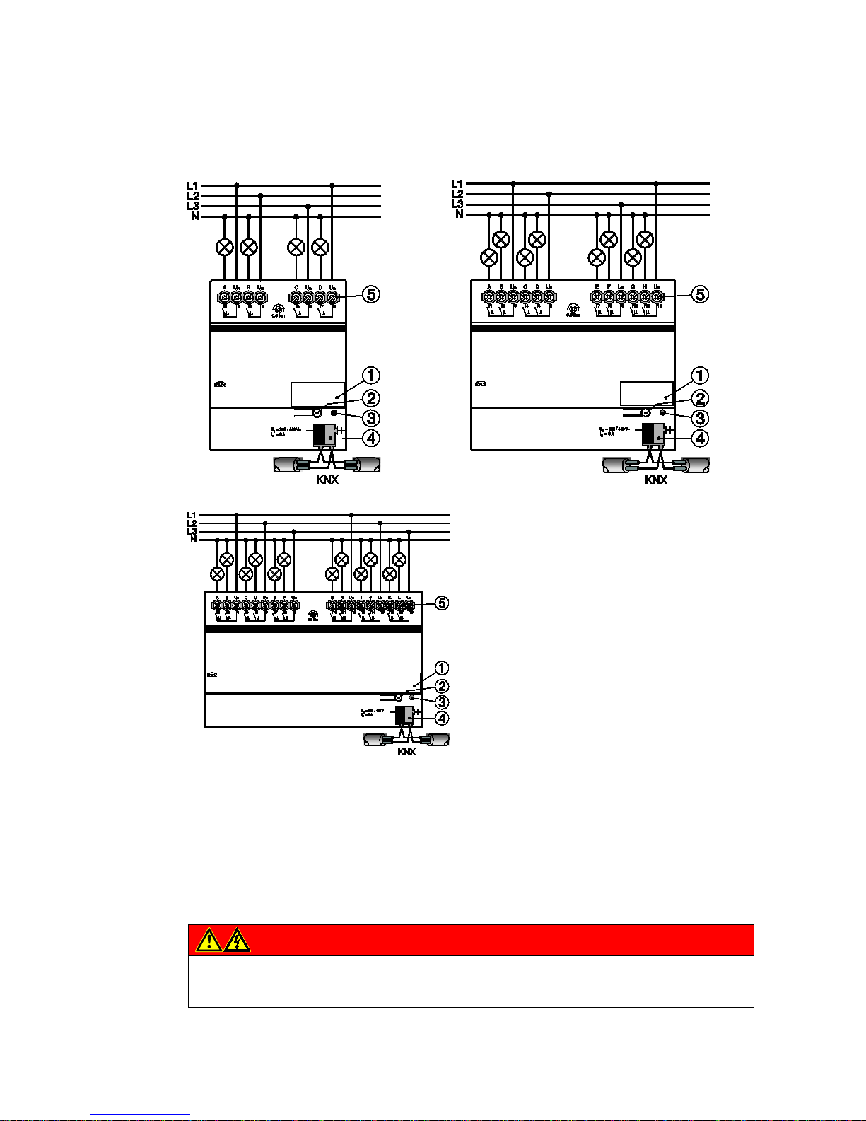
ABB i-bus KNX
Device technology
12 2CDC 505 056 D0208 | SA/S
2.1.3 Connection schematic SA/S x.6.1.1
1 Label carrier
2 Programming button
3 Programming LED
4 Bus connection terminal
5 Load current circuits, one screw terminal for phase connection per contact
Danger
Touch voltages.
Danger of injury.
Observe all-pole disconnection.
2CDC 072 07x F0011

ABB i-bus KNX
Device technology
SA/S | 2CDC 505 056 D0208 13
2.1.4 Dimension drawing SA/S x.6.1.1
SA/S 4.6.1.1
SA/S 8.6.1.1
SA/S 12.6.1.1
Width W
Mounting width
(18 mm modules)
72 mm
4 units
108 mm
6 units
144 mm
8 units
2CDC 072 077 F0011
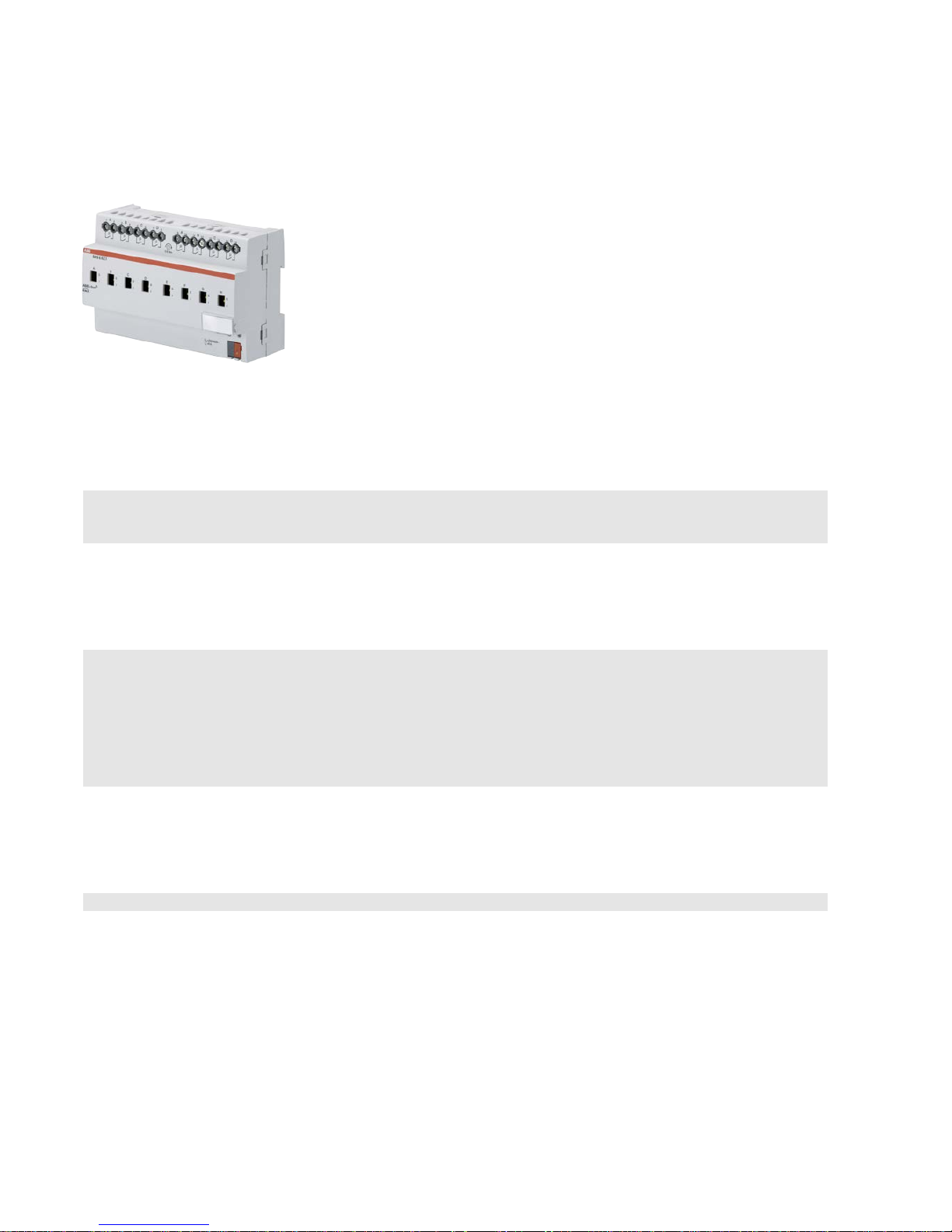
ABB i-bus KNX
Device technology
14 2CDC 505 056 D0208 | SA/S
2.2 Switch Actuators SA/S x.6.2.1, 6 A, manual, MDRC
SA/S
8.6.2.1
Switch Actuators SA/S
x.6.2.1, 6 A are
mod
ular installation devices in ProM
design for installation in the distribution
board. They are suitable for switching
resistive, inductive and capacit iv e loads as
well as fluorescent lamp loads (AX) to
EN
60 669.
The Switch Actuator can be actuated
manually
using a button. This
simultaneously indicates the contact
position.
The actuators can switch up to
12 independent electrical loads via
floating contacts. The connection of the
outputs is implemented using combohead screw terminals. Each output is
controlled separately via KNX.
The device does not require an
additional power supply and is ready for
immediate use after the bus voltage has
been applied.
The Switch Actuators are parameterized
via ETS. Connection to KNX is
implemented using the bus connection
terminal on the front.
2.2.1 Technical data
Supply
KNX bus voltage 21…31 V DC
Current consumption via bus < 12 mA
Power consumption via bus Maximum 250 mW
Rated output value
SA/S type 2.6.2.1 4.6.2.1 8.6.2.1 12.6.2.1
C
urrent detection no no no no
N
umber (floating contacts) 2 4 8 12
Un rated voltage
250/440 V AC (50/60 Hz)
In rated current
6 AX 6 AX 6 AX 6 AX
Leakage loss per device at max. load 0.9 W 1.2 W 1.5 W 3.9 W
Output switching current
AC3
1)
operation (cos ϕ = 0.45)
To EN 60 947-4-1
6 A/230 V AC
AC1
1)
operation (cos ϕ = 0.8)
To EN 60 947-4-1
6 A/230 V AC
Fluorescent lighting load to EN 60 669-1
6 AX/250 V AC (140 µF)2)
Minimum switching ca p acity 100 mA/12 V AC
100 mA/24 V AC
DC current switching capacity (resistive load) 6 A/24 V DC
Output service life
Mechanica l service life
> 3 x 10⁶
Electrical endurance
To IEC 60 947-4-1
A
C1
1)
(240 V/cos ϕ = 0.8)
> 105
AC31) (240 V/cos ϕ = 0.45)
> 3 x 10⁴
AC5a 1) (240 V/cos ϕ = 0.45)
> 3 x 10⁴
2CDC 071 001 S0013

ABB i-bus KNX
Device technology
SA/S | 2CDC 505 056 D0208 15
Output switching times3)
SA/S type
Maximum output relay position change per
minute if all relays are switche d simultaneo usly.
The position changes should be distributed
equally within the minute.
2.6.2.1 4.6.2.1 8.6.2.1 12.6.2.1
60 30 15 10
Maximum output relay position change per
minute if only one relay is switched.
120 120 120 120
Connections
KNX Via bus connection terminals,
0.8 mm Ø, solid
L
oad circuits Universal head screw terminal (PZ 1)
0.2… 4 mm
2
fine stranded, 2 x 0.2…2.5 mm2
0.2… 6 mm
2
solid, 2 x 0.2…4 mm2
F
errules without/with plastic sleeves
0.25…2.5/4 mm
2
T
WIN ferrules
0.5…2.5 mm
2
Contact pin length min. 10 mm
T
ightening torque max. 0.6 Nm
Operating and display elements
Programming button/LED For assignment of the physical address
Contact position display Relay operator
Degree of protection
IP 20
To EN 60 529
Protection class
II To EN 61 140
Isolation category
Overvoltage category III to EN 60 664-1
P
ollution degree 2 to EN 60 664-1
KNX safety extra low voltage
SELV 24 V DC
Temperature range
Operation
Storage
Transport
- 5 °C…+45 °C
-25 °C…+55 °C
-25 °C…+70 °C
Ambient conditions
Maximum a ir humidity
95 %, no condensation allowed
Design
Modular installation device (MDRC)
Modular installation device, ProM
SA/S type 2.6.2.1 4.6.2.1 8.6.2.1 12.6.2.1
D
imensions 90 x W x 64.5 mm (H x W x D)
W
idth W in mm 36 72 144 216
M
ounting width in units (18 mm modules) 2 4 8 12
M
ounting depth in mm 64.5 64.5 64.5 64.5
Weight
in kg 0.15 0.25 0.46 0.65
Mounting
On 35 mm mounting rail To EN 60 715
Mounting position
any
Housing/color
Plastic housing, gray
Approvals
KNX to EN 50 090-1, -2
Certification
CE mark
in accordance with the EMC guideline and
low voltage guideline
1)
Further information concerning electrica l endurance to IEC 60 94 7-4-1 can be found at: AC1, AC3, AX, C-load specifications, p. 43
2)
The maximum inrush current peak may not be exceeded.
3)
The specifications apply only after the bus voltage has been applied to the device for at least 30 seconds. Typical relay delay is approx. 20 ms.

ABB i-bus KNX
Device technology
16 2CDC 505 056 D0208 | SA/S
2.2.2 Lamp output load, 6 A
Lamps
Incande s cent lamp load 1,380 W
Fluorescent lamps T5/T8
Uncorrected
Parallel compensated
DUO circuit
1,380 W
1,380 W
1,380 W
Low-voltage halogen lamps
Inductive transform e r
Electronic transfor mer
Halogen lamps 230 V
1,200 W
1,380 W
1,380 W
Dulux lamp
Uncorrected
Parallel compensated
1,100 W
1,100 W
Mercury-vapor lamp
Uncorrected
Parallel compensated
1,380 W
1,380 W
Switching capacity (switchi ng conta c t )
Maximum peak inrush current Ip (150 µs)
Maximum peak inrush current Ip (250 µs)
Maximum peak inrush current Ip (600 µs)
400 A
320 A
200 A
Number of electronic ballasts (T5/T8, single
element)1)
18 W (ABB EVG 1 x 18 SF)
24 W (ABB EVG-T5 1 x 24 CY)
36 W (ABB EVG 1 x 36 CF)
58 W (ABB EVG 1 x 58 CF)
80 W (Helvar EL 1 x 80 SC)
23
23
14
11
10
1)
For multiple element lamps or other types, the number of electronic ballas ts mu s t be deter mined usi ng the peak inrush current of the electronic
ballasts, see
Ballast calculation, p. 42.
Device type Application program Maximum number of
communication objects
Maximum number of
group addresses
Maximum number of
associations
SA/S 2.6.2.1 Switch 2f 6AM/…* 34 254 254
SA/S 4.6.2.1 Swit ch 4f 6AM/…* 64 254 254
SA/S 8.6.2.1 Switch 8f 6AM/…* 124 254 254
SA/S 12.6.2.1 Switch 12f 6AM/…* 184 254 254
* … = current version number of the application program
Please note
ETS and the current version of the device application program are required for programming.
The current application program is available for download at www.abb.com/knx. After import into ETS it
can be found under ABB/Output/Binary output xf 6AM/…* (x = 2, 4, 8 or 12).
The device does not support the locking function of a KNX device in ETS. If you inhibit access to all of
the project devices by using a BCU code, it has no effect on this device.
Data can still be read and programmed.
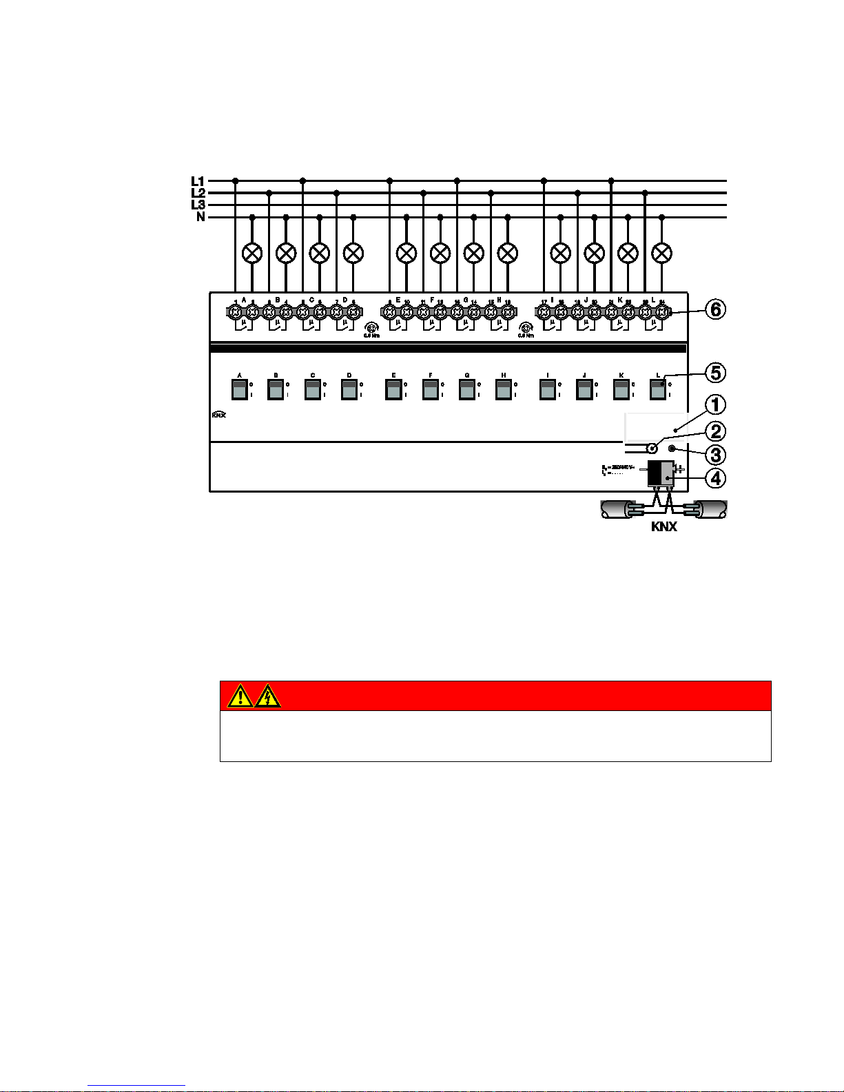
ABB i-bus KNX
Device technology
SA/S | 2CDC 505 056 D0208 17
2.2.3 Connection schematic SA/S x.6.2.1
1 Label carrier
2 Programming button
3 Programming LED
4 Bus connection terminal
5 Contact position display and manual operation
6 Load current circuits, for every 2 connection terminals
Danger
Touch voltages.
Danger of injury.
Observe all-pole disconnection.
2CDC 072 086 F0011
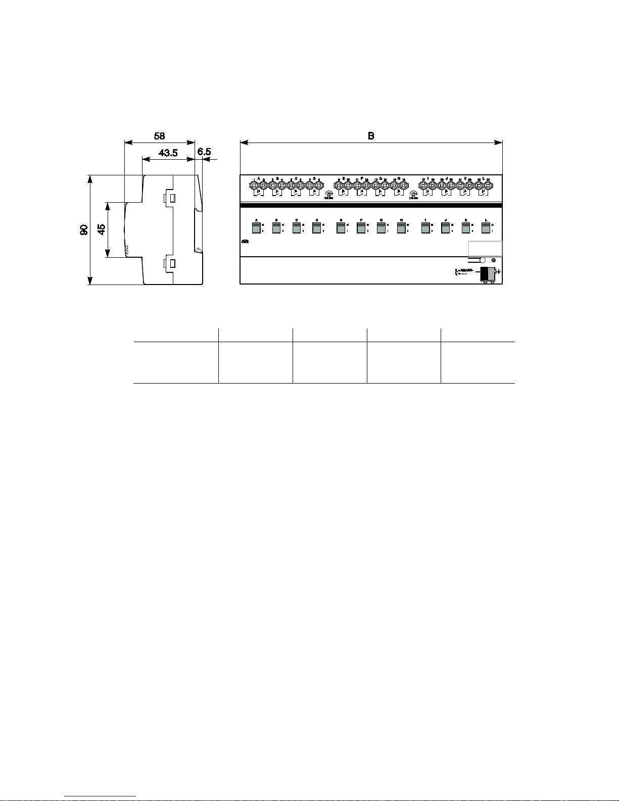
ABB i-bus KNX
Device technology
18 2CDC 505 056 D0208 | SA/S
2.2.4 Dimension drawing SA/S x.6.2.1
SA/S 2.6.2.1 SA/S 4.6.2.1 SA/S 8.6.2.1 SA/S 12.6.2.1
Width W
Mounting width
(18 mm modules)
36 mm
2 units
72 mm
4 units
144 mm
8 units
216 mm
12 units
2CDC 072 019 F0013

ABB i-bus KNX
Device technology
SA/S | 2CDC 505 056 D0208 19
2.3 Switch Actuators SA/S x.10.2.1, 10 A, MDRC
SA/S
8.10.2.1
Switch Actuators SA
/S x.6.2.1, 10 A are
modular installation devices in Pro
M
design for installation in the distribution
board. They are suitable for switching
resistive, inductive and capacit iv e loads as
well as fluorescent lamp loads (AX) to
EN
60 669.
The Switch Actuator
can be actuated
manually using a button. This
simultaneously indicates the contact
position.
The Switch Actuators can switch up to
12 independent electrical loads via
floating contacts. The connection of the
outputs is implemented using combohead screw terminals. Each output is
controlled separately via KNX.
The device does not require an
additional power supply and is ready for
immediate use, after the bus voltage has
been applied.
The Switch Actuators are parameterized
via ETS. Connection to KNX is
implemented using the bus connection
terminal on the front.
2.3.1 Technical data
Supply
KNX bus voltage 21…31 V
Current consumption via bus < 12 mA
Power consumption via bus Maximum 250 mW
Rated output value
SA/S type
2.10.2.1 4.10.2.1 8.10.2.1 12.10.2.1
Current detection
no no no no
Number (floating contacts 2/group) 2 4 8 12
Un rated voltage 250/440 V AC (50/60 Hz)
I
n
rated current 10 AX 10 AX 10 AX 10 AX
L
eakage loss per device at max. load 1.5 W 2.0 W 2.5 W 6.5 W
Output switching current
AC3
1)
operation (cos ϕ = 0.45)
To EN 60 947-4-1
8 A / 230 V AC
AC1
1)
operation (cos ϕ = 0.8)
To EN 60 947-4-1
10 A / 230 V AC
Fluorescent lighting load to EN 60 669-1
Minimum switching ca p acity
DC current switching capacity (resistive load)
Output service life
Mechanica l service life
10 AX/250 V AC (140 µF)
2)
100 mA/12 V AC
100 mA/24 V AC
10 A/24 V DC
> 3 x 10⁶
Electrical endurance
To IEC 60 947-4-1
A
C1
1)
(240 V/cos ϕ = 0.8)
> 105
AC31) (240 V/cos ϕ = 0.45)
> 3 x 10⁴
AC5a 1) (240 V/cos ϕ = 0.45)
> 3 x 10⁴
2CDC 071 016 S0012

ABB i-bus KNX
Device technology
20 2CDC 505 056 D0208 | SA/S
Output switching times3)
Maximum r elay position chan ge of output and
minute if all relays are switched simultane o usly.
The position changes should be distributed
equally within the minute.
2.10.2.1 4.10.2.1 8.10.2.1 12.10.2.1
60 30 15 10
Maximum output relay position change per
minute if only one relay is switched.
120 120 120 120
Connections
KNX
Via bus connection terminals,0.8 mm Ø, solid
Load current circuits (1 terminal per contact)
Universal head screw terminal (PZ 1)
0.2… 4 mm
2
fine stranded, 2 x 0.2…2.5 mm2
0.2… 6 mm
2
solid, 2 x 0.2…4 mm2
F
errules without/with plastic sleeves
0.25…2.5/4 mm
2
T
WIN ferrules
0.5…2.5 mm
2
Contact pin length min. 10 mm
Tightening torque max. 0.6 Nm
Operating and display elements
Programming button/LED For assignment of the physical address
Contact position display Relay operator
Degree of protection
IP 20 To EN 60 529
Protection class
II To EN 61 140
Isolation category
Overvoltage category III to EN 60 664-1
Pollution degree
2 to EN 60 664-1
KNX safety extra low voltage
SELV 24 V DC
Temperature range
Operation
Storage
Transport
- 5 °C…+45 °C
-25 °C…+55 °C
-25 °C…+70 °C
Ambient conditions
Maximum a ir humidity 95 %, no condensation allowed
Design
Modular installation device (MDRC) Modular installation device, ProM
SA
/S type 2.10.2.1 4.10.2.1 8.10.2.1 12.10.2.1
Dimensions
90 x W x 64.5 mm (H x W x D)
Width W in mm
36 72 144 216
Mounting width in units (18 mm modules) 2 4 8 12
Mounting depth in mm 64.5 64.5 64.5 64.5
Weight
in kg 0.15 0.25 0.46 0.65
Mounting
On 35 mm mounting rail To EN 60 715
Mounting position
As required
Housing/color
Plastic housing, gray
Approvals
KNX to EN 50 090-1, -2
Certification
CE mark
in accordance with the EMC guideline and
low voltage guideline
1)
Further information concerning electrical endurance to IEC 60 947-4-1 can be found at: AC1, AC3, AX, C-load specif ications, p. 43
2)
The maximum inrush current peak may not be exceeded.
3)
The specifications apply only after the bus voltage has been applied to the device for at least 30 seconds. Typical relay delay is approx. 20 ms.

ABB i-bus KNX
Device technology
SA/S | 2CDC 505 056 D0208 21
2.3.2 Lamp output load 10 A
Lamps
Incande s cent lamp load 2,500 W
Fluorescent lamps T5/T8
Uncorrected
Parallel compensated
DUO circuit
2,500 W
1,500 W
1,500 W
Low-voltage halogen lamps
Inductive transform e r
Electronic transfor mer
Halogen lamps 230 V
1,200 W
1,500 W
2,500 W
Dulux lamp
Uncorrected
Parallel compensated
1,100 W
1,100 W
Mercury-vapor lamp
Uncorrected
Parallel compensated
2,000 W
2,000 W
Switching capacity (switchi ng conta c t )
Maximum peak inrush current I
p
(150 µs)
Maximum peak inrush current I
p
(250 µs)
Maximum peak inrush current I
p
(600 µs)
400 A
320 A
200 A
Number of electronic ballasts (T5/T8, single
element)1)
18 W (ABB EVG 1 x 18 SF)
24 W (ABB EVG-T5 1 x 24 CY)
36 W (ABB EVG 1 x 36 CF)
58 W (ABB EVG 1 x 58 CF)
80 W (Helvar EL 1 x 80 SC)
23
23
14
11
10
1)
For multiple element lamps or other types, the number of electronic ballas ts mu s t be deter mined usi ng the peak inrush current of the electronic
ballasts, see
Ballast calculation, p. 42.
Device type Application program Maximum number of
communication objects
Maximum number of
group addresses
Maximum number of
associations
SA/S 2.10.2.1 Switch 2f 10 A/…* 34 254 254
SA/S 4.10.2.1 Switch 4f 10 A/…* 64 254 254
SA/S 8.10.2.1 Switch 8f 10 A/…* 124 254 254
SA/S 12.10.2.1 Switch 12f 10A/…* 184 254 254
* … = current version number of the application program
Please note
ETS and the current version of the device application program are required for programming.
The current application program is available for download at www.abb.com/knx. After import into ETS,
it is available in ETS under ABB/Output/Binary output xf 10A/…* (x = 2, 4, 8 or 12).
The device does not support the locking function of a KNX device in ETS. If you inhibit access to all of
the project devices by using a BCU code, it has no effect on this device.
Data can still be read and programmed.
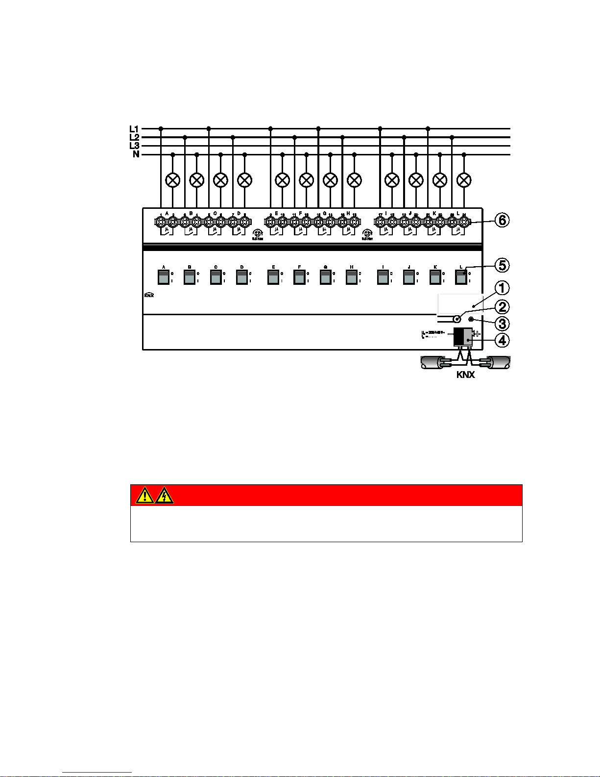
ABB i-bus KNX
Device technology
22 2CDC 505 056 D0208 | SA/S
2.3.3 Connection schematic SA/S x.10.2.1
1 Label carrier
2 Programming button
3 Programming LED
4 Bus connection terminal
5 Contact position display and manual operation
6 Load current circuits, for every 2 connection terminals
Danger
Touch voltages.
Danger of injury.
Observe all-pole disconnection.
2CDC 072 086 F0011
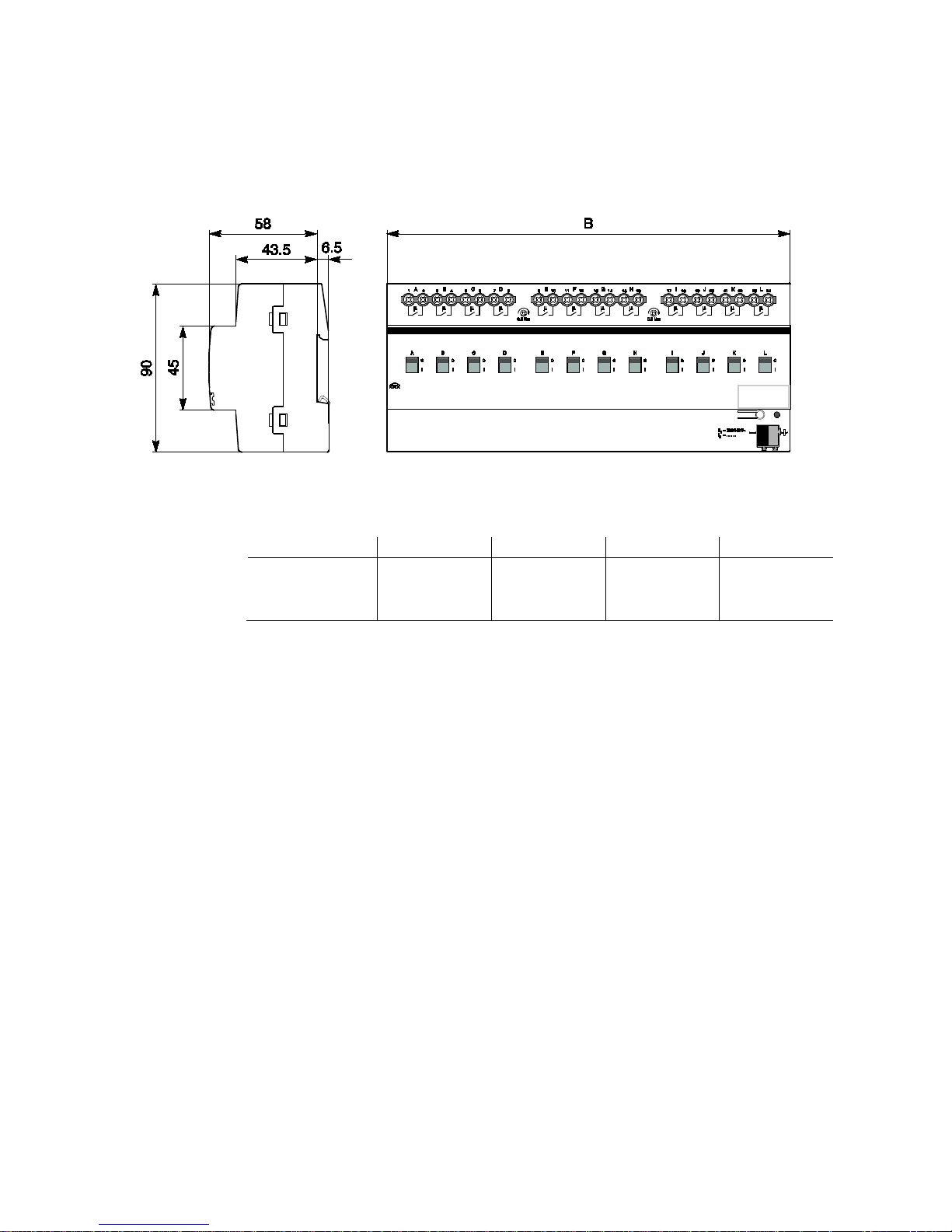
ABB i-bus KNX
Device technology
SA/S | 2CDC 505 056 D0208 23
2.3.4 Dimension drawing SA/S x.10.2.1
SA/S 2.10.2.1
SA/S 4.10.2.1
SA/S 8.10.2.1
SA/S 12.10.2.1
Width W
Mounting width
(18 mm modules)
36 mm
2 units
72 mm
4 units
144 mm
8 units
216 mm
12 units
2CDC 072 019 F0013
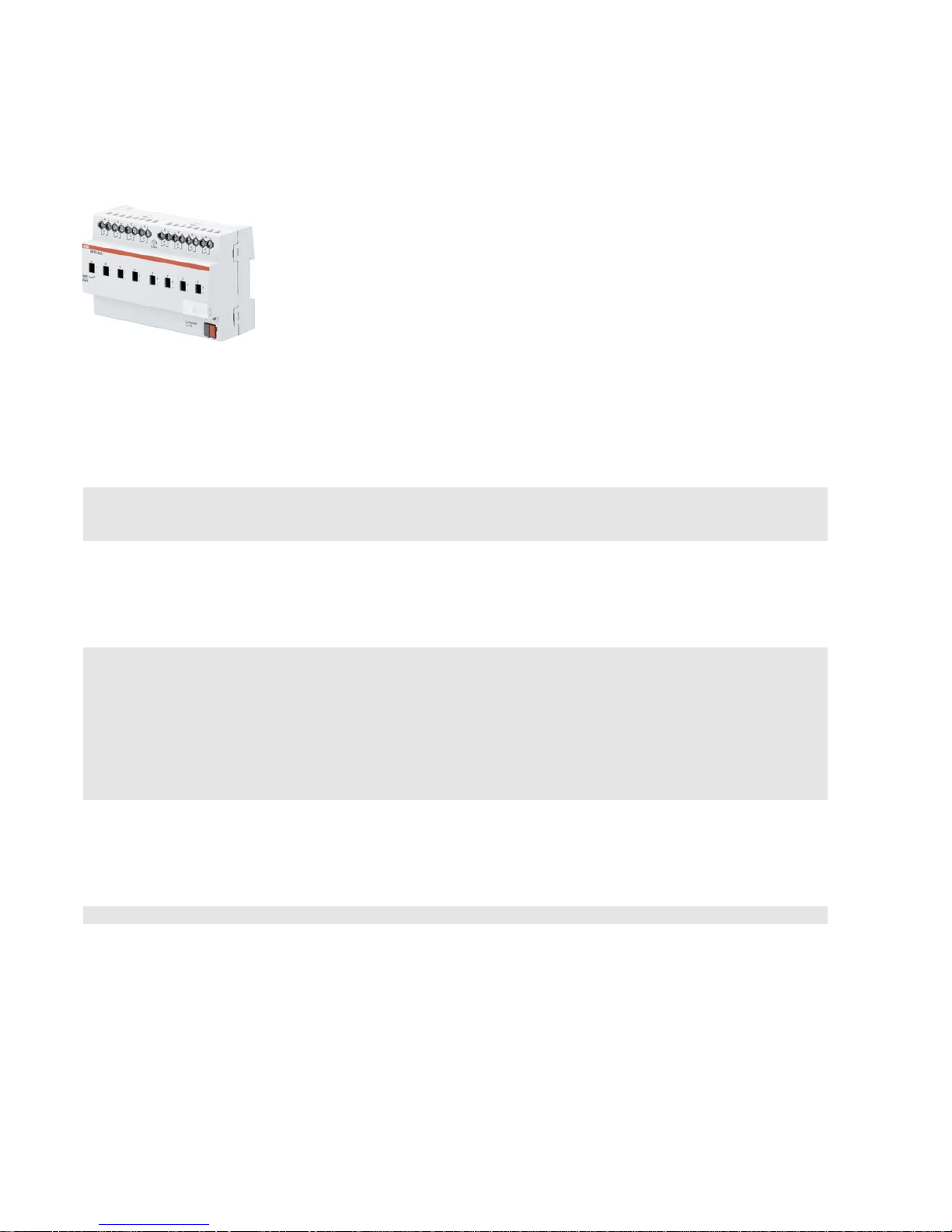
ABB i-bus KNX
Device technology
24 2CDC 505 056 D0208 | SA/S
2.4 Switch Actuators SA/S x.16.2.1, 16 A MDRC
SA/S
8.16.2.1
Switch Actuators SA/S x.16.2.1, 16 A are
modular installation devices in ProM
design for installation in the distribution
board. They are especially suitable for
switching resistive loads.
The Switch Actuator can be actuated
manually using a button. This
simultaneously indicates the c ont a ct
position.
The Switch Actuators can switch up to
12 independent electrical loads via
floating contacts. The connection of the
outputs is implemented using combohead screw terminals. Each output is
controlled separately via KNX.
The device does not require an
additional power supply and is ready for
immediate use, after the bus voltage has
been applied.
The Switch Actuators are parameterized
via ETS. Connection to KNX is
implemented using the bus connection
terminal on the front.
2.4.1 Technical data
Supply
KNX bus voltage 21…31 V DC
Current consumption via bus < 12 mA
Power consumption via bus Maximum 250 mW
Rated output value
SA/S type 2.16.2.1 4.16.2.1 8.16.2.1 12.16.2.1
Current detection
no no no no
Number (floating contacts 2/group)
2 4 8 12
Un rated voltage 250/440 V AC (50/60 Hz)
In rated current 16 A 16 A 16 A 16 A
L
eakage loss per device at max. load 2.0 W 4.0 W 8.0 W 12.0 W
Output switching current
AC3
1)
operation (cos ϕ = 0.45)
To EN 60 947-4-1
8 A / 230 V AC
AC1
1)
operation (cos ϕ = 0.8)
To EN 60 947-4-1
16 A/230 V AC
Fluorescent lighting load to EN 60 669-1
Minimum switching ca p acity
DC current switching capacity (resistive load)
Output service life
Mechanica l service life
16 AX/250 V AC (70 µF)
2)
100 mA/12 V AC
100 mA/24 V AC
16 A/24 V DC
> 3 x 10⁶
Electrical endurance
To IEC 60 947-4-1
AC11) (240 V/cos ϕ = 0.8)
> 105
AC31) (240 V/cos ϕ = 0.45)
> 3 x 10⁴
AC5a1) (240 V/cos ϕ = 0.45)
> 3 x 10⁴
2CDC 071 017 S0012

ABB i-bus KNX
Device technology
SA/S | 2CDC 505 056 D0208 25
Output switching times3)
Maximum r elay position chan ge of output and
minute if all relays are switched simultane o usly.
The position changes should be distributed
equally within the minute.
2.10.2.1 4.10.2.1 8.10.2.1 12.10.2.1
60 30 15 10
Maximum output relay position change per
minute if only one relay is switched.
120 120 120 120
Connections
KNX
Via bus connection terminals,0.8 mm Ø, solid
Load current circuits (1 terminal per contact)
Universal head screw terminal (PZ 1)
0.2… 4 mm
2
fine stranded, 2 x 0.2…2.5 mm2
0.2… 6 mm
2
solid, 2 x 0.2…4 mm2
F
errules without/with plastic sleeves
0.25…2.5/4 mm
2
T
WIN ferrules
0.5…2.5 mm
2
Contact pin length min. 10 mm
Tightening torque max. 0.6 Nm
Operating and display elements
Programming button/LED For assignment of the physical address
Contact position display Relay operator
Degree of protection
IP 20 To EN 60 529
Protection class
II To EN 61 140
Isolation category
Overvoltage category III to EN 60 664-1
Pollution degree
2 to EN 60 664-1
KNX safety extra low voltage
SELV 24 V DC
Temperature range
Operation
Storage
Transport
- 5 °C…+45 °C
-25 °C…+55 °C
-25 °C…+70 °C
Ambient conditions
Maximum a ir humidity 95 %, no condensation allowed
Design
Modular installation device (MDRC) Modular installation device, ProM
SA/
S type 2.10.2.1 4.10.2.1 8.10.2.1 12.10.2.1
Dimensions
90 x W x 64.5 mm (H x W x D)
Width W in mm
36 72 144 216
Mounting width in units (18 mm modules) 2 4 8 12
Mounting depth in mm 64.5 64.5 64.5 64.5
Weight
in kg 0.15 0.25 0.46 0.65
Mounting
On 35 mm mounting rail To EN 60 715
Mounting position
any
Housing/color
Plastic housing, gray
Approvals
KNX to EN 50 090-1, -2
Certification
CE mark
in accordance with the EMC guideline and
low voltage guideline
1)
Further information concerning electrical endurance to IEC 60 947-4-1 can be found at: AC1, AC3, AX, C-load specifications, p. 43
2)
The maximum inrush current peak may not be exceeded.
3)
The specifications apply only after the bus voltage has been applied to the device for at least 30 seconds. Typical relay delay is approx. 20 ms.

ABB i-bus KNX
Device technology
26 2CDC 505 056 D0208 | SA/S
2.4.2 Lamp output load 16 A
Lamps
Incande s cent lamp load 2,500 W
Fluorescent lamps T5/T8
Uncorrected
Parallel compensated
DUO circuit
2,500 W
1,500 W
1,500 W
Low-voltage halogen lamps
Inductive transform e r
Electronic transfor mer
Halogen lamps 230 V
1,200 W
1,500 W
2,500 W
Dulux lamp
Uncorrected
Parallel compensated
1,100 W
1,100 W
Mercury-vapor lamp
Uncorrected
Parallel compensated
2,000 W
2,000 W
Switching capacity (switchi ng conta c t )
Maximum peak inrush current I
p
(150 µs)
Maximum p eak inrush curren t I
p
(250 µs)
Maximum peak inrush current I
p
(600 µs)
400 A
320 A
200 A
Number of electronic ballasts (T5/T8, single
element)1)
18 W (ABB EVG 1 x 18 SF)
24 W (ABB EVG-T5 1 x 24 CY)
36 W (ABB EVG 1 x 36 CF)
58 W (ABB EVG 1 x 58 CF)
80 W (Helvar EL 1 x 80 SC)
23
23
14
11
10
1)
For multiple element lamps or other types, the number of electronic ballas ts mu s t be deter mined usi ng the peak inrush
current of the electronic ballasts, see
Ballast calculation, p. 42
Device type
Application program
Maximum number of
communication objects
Maximum number of
group addresses
Maximum number of
associations
SA/S 2.10.2.1 Switch 2f 10 A/…* 34 254 254
SA/S 4.10.2.1
Switch 4f 10A/…*
64
254
254
SA/S 8.10.2.1
Switch 8f 10A/…*
124
254
254
SA/S 12.10.2.1 Switch 12f 10A/…* 184 254 254
* … = current version number of the application program
Please note
ETS and the current version of the device application program are required for programming.
The current application program is available for download at www.abb.com/knx. After import into ETS,
it is available in ETS under ABB/Output/Binary output xf 10A/…* (x = 2, 4, 8 or 12).
The device does not support the locking function of a KNX device in ETS. If you inhibit access to all
devices of the project with a BCU code, it has no effect on this device.
Data can still be read and programmed.

ABB i-bus KNX
Device technology
SA/S | 2CDC 505 056 D0208 27
2.4.3 Connection schematic SA/S x.16.2.1
1 Label carrier
2 Programming button
3 Programming LED
4 Bus connection terminal
5 Contact position display and manual operation
6 Load current circuits, for every 2 connection terminals
Danger
Touch voltages.
Danger of injury.
Observe all-pole disconnection.
2CDC 072 086 F0011

ABB i-bus KNX
Device technology
28 2CDC 505 056 D0208 | SA/S
2.4.4 Dimension drawing SA/S x.16.2.1
SA/S 2.16.2.1
SA/S 4.16.2.1
SA/S 8.16.2.1
SA/S 12.16.2.1
Width W
Mounting width
(18 mm modules)
36 mm
2 units
72 mm
4 units
144 mm
8 units
216 mm
12 units
2CDC 072 019 F0013

ABB i-bus KNX
Device technology
SA/S | 2CDC 505 056 D0208 29
2.5 Switch Actuator SA/S 16.5.1, 16/20 A, MDRC
SA/S
12.16.5.1
Switch Actuat
ors SA/S x.16.5.1, 16/20 A
are modular installation devices in Pro
M
design for installation in the distribution
board. They are especially suitable for
switching loads with high peak inrush
currents such as lighting equipment with
compensation capacitors o
r fluorescent
lamp loads (AX) to EN
60 669.
Manual actuation of the Switch Actuator is
possible using a button. This
simultaneously indicates the contact
position.
The Switch Actuators can switch up to
12 independent electrical loads via
floating contacts. The maximum load
current per output is 20 A. The
connection of the outputs is implemented
using combo-
head screw terminals. Each
output is controlled separately via KNX.
The devices do not require an additional
power supply and are ready for
immediate use, after the bus voltage
has
been applied.
The Switch Actuators are parameterized
via ETS. Connection to KNX is
implemented using the bus connection
terminal on the front.
2.5.1 Technical data
Supply
KNX bus voltage 21…31 V DC
Current consumption via bus
< 12 mA
Power consumption via bus
Maximum 250 mW
Rated output value
SA/S type 2.16.5.1 4.16.5.1 8.16.5.1 12.16.5.1
Current detection no no no no
N
umber (floating contacts) 2 4 8 12
U
n
rated voltage 250/440 V AC (50/60 Hz)
I
n
rated current 16/20 AX, C-load
L
eakage loss per device at max. load 16 A 2.0 W 4.0 W 8.0 W 12 W
L
eakage loss per device at max. load 20 A 3.0 W 5.5 W 11.0 W 16 W
Output switching current
AC3
1)
operation (cos ϕ = 0.45)
To EN 60 947-4-1
16 A/230 V AC
AC1
1)
operation (cos ϕ = 0.8)
To EN 60 947-4-1
16/20 A/230 V AC
Fluorescent lighting load to EN 60 669-1 16/20 AX/250 V AC (200 µF)2)
Minimum switching ca p acity 100 mA/12 V AC
100 mA/24 V AC
DC current switching capacity (resistive load) 20 A/24 V DC
Output service life
Mechanical service life > 106
E
lectrical endurance to IEC 60 947-4-1
AC11) (240 V/cos ϕ = 0.8)
> 105
AC31) (240 V/cos ϕ = 0.45)
> 3 x 10⁴
A
C5a
1)
(240 V/cos ϕ = 0.45)
> 3 x 10⁴
2CDC 071 001 S0011

ABB i-bus KNX
Device technology
30 2CDC 505 056 D0208 | SA/S
Output switching times3)
Maximum r elay position chan ges
per output per minute if all
relays are switched simultaneously.
Position changes should be
distributed equally within the minute.
2.16.5.1 4.16.5.1 8.16.5.1 12.16.5.1
30 15 7 5
Maximum r elay position chan ges
per output per minute if only
one relay is switched.
60 60 60 60
Connections
KNX Via bus connection terminals,
0.8 mm Ø, solid
L
oad circuits Universal head screw terminal (PZ 1)
0.2… 4 mm
2
fine stranded, 2 x 0.2…2.5 mm2
0.2… 6 mm
2
solid, 2 x 0.2…4 mm2
F
errules without/with plastic sleeves
0.25…2.5/4 mm
2
TWIN ferrules
0.5…2.5 mm
2
Contact pin length min. 10 mm
T
ightening torque max. 0.6 Nm
Operating and display elements
Programming button/LED For assignment of the physical address
Contact position display Relay operator
Degree of protection
IP 20
To EN 60 529
Protection class
II
To EN 61 140
Isolation category
Overvoltage category III to EN 60 664-1
P
ollution degree 2 to EN 60 664-1
KNX safety extra low voltage
SELV 24 V DC
Temperature range
Operation
Storage
Transport
- 5 °C…+45 °C
-25…+55 °C
-25…+70 °C
Ambient conditions
Maximum a ir humidity
95 %, no condensation allowed
Design
Modular installation device (MDRC) 2.16.5.1 4.16.5.1 8.16.5.1 12.16.5.1
Dimensions 90 x W x 64.5 mm (H x W x D)
W
idth W in mm 36 72 144 216
M
ounting width in units (18 mm modules) 2 4 8 12
M
ounting depth in mm 64.5 64.5 64.5 64.5
Weight
in kg 0.2 0.34 0.64 0.75
Mounting
On 35 mm mounting rail
To EN 60 715
Mounting position
any
Housing/color
Plastic housing, gray
Approvals
KNX to EN 50 090-1, -2 Certification
CE mark
in accordance with the EMC guideline and
low voltage guideline
1)
Further information concerning electrical endurance to IEC 60 947-4-1 can be found at: AC1, AC3, AX, C-load specifications, p. 43
2)
The maximum inrush current peak may not be exceeded.
3)
The specifications apply only after the bus voltage has been applied to the device for at least 30 seconds. Typical relay delay is approx. 20 ms.
ABB i-bus KNX
Device technology
SA/S | 2CDC 505 056 D0208 31
2.5.2 Lamp output load 16/20 A
Lamps
Incande s cent lamp load 3,680 W
Fluorescent lamps T5/T8
Uncorrected
Parallel compensated
DUO circuit
3,680 W
2,500 W
3,680 W
Low-voltage halogen lamps
Inductive transformer
Electronic transfor mer
Halogen lamps 230 V
2,000 W
2,500 W
3,680 W
Dulux lamp
Uncorrected
Parallel compensated
3,680 W
3,000 W
Mercury-vapor lamp
Uncorrected
Parallel compensated
3,680 W
3,680 W
Switching capacity (switchi ng conta c t )
Maximum peak inrush current I
p
(150 µs)
Maximum peak inrush current I
p
(250 µs)
Maximum peak inrush current I
p
(600 µs)
600 A
480 A
300 A
Number of electronic ballasts (T5/T8, single
element)1)
18 W (ABB EVG 1 x 18 SF)
24 W (ABB EVG-T5 1 x 24 CY)
36 W (ABB EVG 1 x 36 CF)
58 W (ABB EVG 1 x 58 CF)
80 W (Helvar EL 1 x 80 SC)
26
2)
26
2)
22
12
2)
102)
1)
For multiple element lamps or other types, the number of electronic ballas ts mu s t be deter mined usi ng the peak inrush current of the electronic
ballasts, see
Ballast calculation, p. 42.
2)
The number of ballasts is limited by protection with B16 circuit-breakers.
Device type
Application program
Maximum number of
communication objects
Maximum number of
group addresses
Maximum number of
associations
SA/S 2.16.5.1 Switch 2f 16C/…* 34 254 254
SA/S 4.16.5.1
Switch 4f 16C/…*
64
254
254
SA/S 8.16.5.1
Switch 8f 16C/…*
124
254
254
SA/S 12.16.5.1 Switch 12f 16C/…* 184 254 254
* … = current version number of the application program
Please note
ETS and the current version of the device application program are required for programming.
The current application program is available for download at www.abb.com/knx. After import into ETS,
it is available in ETS under ABB/Output/Binary output xf 16C/…* (x = 2, 4, 8 or 12).
The device does not support the locking function of a KNX device in ETS. If you inhibit access to all of
the project devices by using a BCU code, it has no effect on this device.
Data can still be read and programmed.
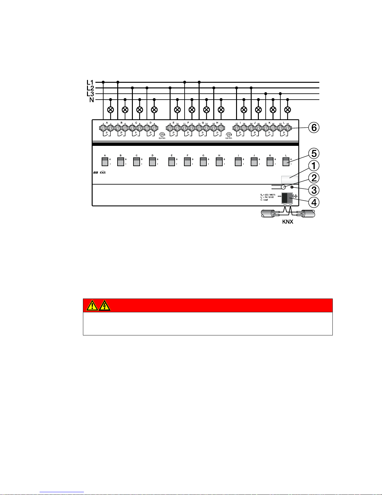
ABB i-bus KNX
Device technology
32 2CDC 505 056 D0208 | SA/S
2CDC 072 177 F0009
2.5.3 Connection schematic SA/S 12.16.5.1
1 Label carrier
2 Programming button
3 Programming LED
4 Bus connection terminal
5 Contact position display and manual operation
6 Load current circuits, for every 2 connection terminals
Danger
Touch voltages.
Danger of injury.
Observe all-pole disconnection.
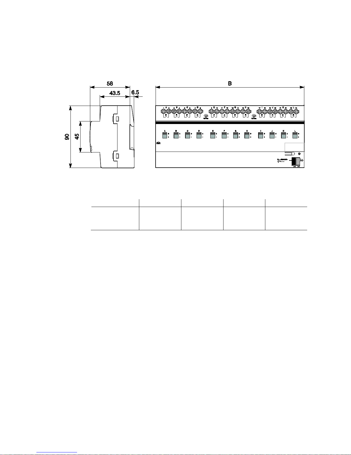
ABB i-bus KNX
Device technology
SA/S | 2CDC 505 056 D0208 33
2.5.4 Dimension drawing SA/S 12.16.5.1
SA/S 2.16.5.1 SA/S 4.16.5.1 SA/S 8.16.5.1 SA/S 12.16.5.1
Width W
Mounting width
(18 mm modules)
36 mm
2 units
72 mm
4 units
144 mm
8 units
216 mm
12 units
2CDC 072 019 F0013
 Loading...