

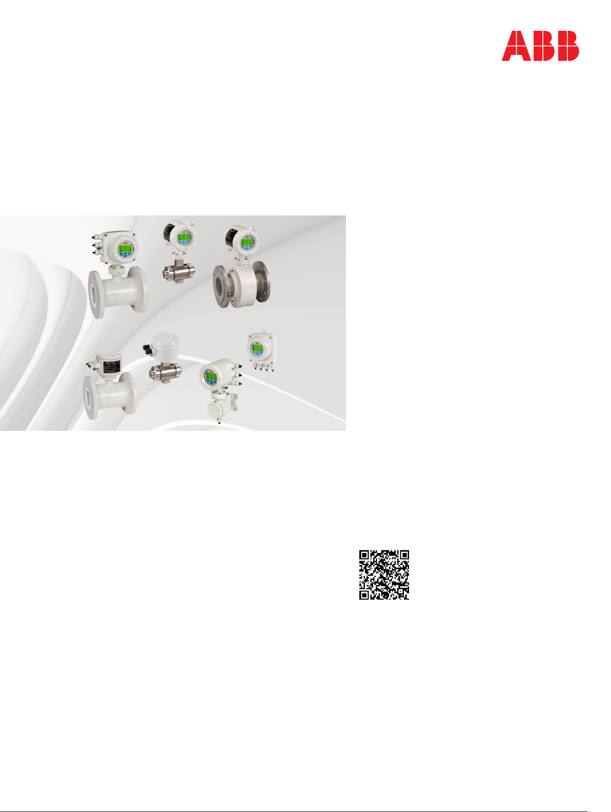
ABB HygienicMaster FEH631, ProcessMaster FEP631, HygienicMaster FEH632, HygienicMaster FET632, ProcessMaster FEP632 Operating Instruction
...Page 1
—
ABB MEASUREMENT & ANALYTICS | OPERATING INSTRUCTION
ProcessMaster FEP630, HygienicMaster FEH630
Electromagnetic flowmeter
Devices-Firmware version: 01.07.00
Measurement made easy
—
FEP630
FEH630
FET630
Introduction
Intelligent design and extended functions for
efficient system operation at reduced costs and with
higher profitability.
ProcessMaster FEP630
The first choice for demanding applications in the
processing industry.
HygienicMaster FEH630
The first choice for demanding applications in the
food industry.
Additional Information
Additional documentation on FEP630, FEH630 is
available for download free of charge at
www.abb.com/flow.
Alternatively simply scan this code:
Page 2

2 FEP630, FEH630 ELECTROMAGNETIC FLOWMETER | OI/FEP630/FEH630-EN REV. D
Table of contents
Change from one to two columns
1 Safety .......................................................................... 4
General information and instructions .................................. 4
Warnings .................................................................................... 4
Intended use ............................................................................. 5
Improper use ............................................................................. 5
Use in Potentially Explosive Atmospheres .......................... 5
Notes on data safety ............................................................... 5
Warranty provisions ................................................................. 6
Manufacturer’s address .......................................................... 6
6 Electrical connections .............................................29
Safety instructions ................................................................ 29
Use in Potentially Explosive Atmospheres ................... 29
Sensor grounding .................................................................. 29
General information on grounding ................................ 29
Metal pipe with fixed flanges ......................................... 30
Metal pipe with loose flanges ......................................... 30
Plastic pipes, non-metallic pipes or pipes with
insulating liner ................................................................... 30
Sensor type HygienicMaster ............................................ 31
2 Design and function .................................................. 7
Overview .................................................................................... 7
ProcessMaster ..................................................................... 7
HygienicMaster .................................................................... 8
Transmitter .......................................................................... 9
Model variants ........................................................................ 10
Measuring principle ............................................................... 11
3 Product identification ............................................ 12
Name plate .............................................................................. 12
Additional warning plate ...................................................... 12
4 Transport and storage ............................................ 13
Inspection ................................................................................ 13
Transport ................................................................................. 13
Storing the device .................................................................. 14
Temperature data .................................................................. 14
Returning devices ................................................................... 14
Grounding with conductive PTFE grounding plate ..... 31
Devices with extended diagnostic functions ............... 31
Installation and grounding in piping with cathodic
corrosion protection ......................................................... 31
Power supply .......................................................................... 33
Cable entries ........................................................................... 34
Connection via cable conduit ......................................... 34
Installing the connection cables ......................................... 34
Connection with IP rating IP 68 ........................................... 35
Pin assignment ....................................................................... 37
Electrical data for inputs and outputs .......................... 38
Connection examples ....................................................... 42
Connection to integral mount design ........................... 44
Connection to remote mount design ........................... 46
Digital communication ......................................................... 49
HART® communication .................................................... 49
Modbus® communication ............................................... 49
Cable specification ........................................................... 50
5 Installation ............................................................... 15
PROFIBUS DP® communication ...................................... 50
Safety instructions ................................................................. 15
Use in Potentially Explosive Atmospheres ................... 15
Installation conditions .......................................................... 15
General ................................................................................ 15
Devices with extended diagnostic functions ............... 15
Brackets .............................................................................. 16
Gaskets................................................................................ 16
Devices with a wafer-type design .................................. 16
Flow direction .................................................................... 16
Electrode axis ..................................................................... 17
Mounting position............................................................. 17
Minimum spacing of the devices .................................... 17
Grounding ........................................................................... 18
Sensor insulation ............................................................... 18
Inlet and outlet sections .................................................. 18
Free inlet or outlet ............................................................. 19
Mounting with heavily contaminated measuring media
.............................................................................................. 19
7 Commissioning ........................................................ 52
Safety instructions ................................................................ 52
Use in Potentially Explosive Atmospheres ................... 52
Hardware settings ................................................................. 52
Dual- compartment housing ........................................... 52
Single-compartment housing ......................................... 53
Configuration of digital outputs V1 / V2 or V3 / V4 ... 53
Checks prior to commissioning .......................................... 54
Parameterization of the device ........................................... 54
Parameterization via the local operating interface .... 54
Parameterization via the infrared service port adapter
.............................................................................................. 55
Parameterization via HART® ........................................... 55
Factory settings ..................................................................... 56
Switching on the power supply ........................................... 56
Parameterization via the menu function Easy Setup ...... 56
Measuring range table .......................................................... 60
Mounting with pipe vibration ......................................... 19
Installation in piping with larger nominal diameter ... 20
Installation in 3A compliant installations ..................... 20
Installing the sensor .............................................................. 21
Installing the transmitter in the remote mount design .. 22
Opening and closing the housing ....................................... 23
Adjusting the transmitter position ..................................... 24
Installing the plug-in cards ................................................... 26
Page 3

FEP630, FEH630 ELECTROMAGNETIC FLOWMETER | OI/FEP630/FEH630-EN REV. D 3
8 Operation ................................................................. 61
Safety instructions ................................................................. 61
Menu navigation ..................................................................... 61
Menu levels .............................................................................. 62
Process display ....................................................................... 63
Switching to the information level ...................................... 63
Error messages on the LCD display .............................. 64
Switching to the configuration level
(parameterization) ................................................................ 64
Selecting and changing parameter .................................... 66
Entry from table................................................................ 66
Parameter overview .............................................................. 68
Parameter descriptions ........................................................ 78
Available units .................................................................... 78
Menu: Easy Setup .............................................................. 79
Menu: Device Info ............................................................. 80
Menu: Device Setup ........................................................... 82
Menu: Display ..................................................................... 87
Menu: Input/Output ........................................................ 88
Menu: Process Alarm ....................................................... 94
Menu: Communication ..................................................... 95
Menu: Diagnostics ............................................................. 97
Menu: Totalizer ................................................................ 104
Menu: Sensor Setup ........................................................ 107
Software history ................................................................... 107
Filling function ...................................................................... 108
Setup ................................................................................. 108
Brief overview of configurations ....................................... 108
9 Diagnosis / error messages ................................. 109
Calling up the error description ........................................ 109
Error messages ..................................................................... 110
Overview ................................................................................ 114
Extended diagnostic functions ......................................... 118
Overview ........................................................................... 118
Detection of partial filling .............................................. 118
Detection of gas bubbles............................................... 119
Monitoring the conductivity .......................................... 119
Monitoring the electrode impedance .......................... 120
Measurements on the flowmeter ................................. 120
Monitoring the grounding ............................................. 121
Verification ............................................................................ 121
Fingerprint database ...................................................... 121
11 Repair ...................................................................... 123
Safety instructions ............................................................... 123
Spare parts ........................................................................... 124
Replacing the fuse ............................................................... 124
Replacing the LCD indicator .............................................. 125
Replacing the frontend board ........................................... 126
Integral mount design ................................................... 126
Remote mount design ................................................... 128
Replacing the sensor ........................................................... 129
Returning devices ................................................................ 129
12 Recycling and disposal .......................................... 130
Dismounting ......................................................................... 130
Disposal ................................................................................. 130
13 Specification .......................................................... 131
Permitted pipe vibration ..................................................... 131
ProcessMaster – Temperature data .................................. 131
Maximum permissible cleaning temperature ............. 131
Maximum ambient temperature depending on
measuring medium temperature .................................. 132
ProcessMaster – Material load for process
connections .......................................................................... 136
Minimum permissible operating pressure ................. 136
Material load ..................................................................... 137
HygienicMaster - Temperature data ................................ 140
Maximum permissible cleaning temperature ............ 140
Maximum ambient temperature depending on
measuring medium temperature ................................. 140
HygienicMaster – Material load for process
connections ........................................................................... 141
14 Additional documents ........................................... 142
15 Appendix ................................................................. 143
Return form ........................................................................... 143
Torque information ............................................................. 144
Tightening torques for transducers with
design level ‘A’ ................................................................. 144
Tightening torques for transducers with
design level ‘B’ ................................................................. 149
Tightening torques for HygienicMaster with
variable process connections ........................................ 151
Parameterization overview (factory settings) ................ 151
10 Maintenance ........................................................... 122
Safety instructions ............................................................... 122
Sensor .................................................................................... 123
Gaskets.............................................................................. 123
Cleaning ............................................................................ 123
Page 4

4 FEP630, FEH630 ELECTROMAGNETIC FLOWMETER | OI/FEP630/FEH630-EN REV. D
‘
E
’
1 Safety
General information and instructions
These instructions are an important part of the product and
must be retained for future reference.
Installation, commissioning, and maintenance of the product
may only be performed by trained specialist personnel who have
been authorized by the plant operator accordingly. The specialist
personnel must have read and understood the manual and must
comply with its instructions.
For additional information or if specific problems occur that are
not discussed in these instructions, contact the manufacturer.
The content of these instructions is neither part of nor an
amendment to any previous or existing agreement, promise or
legal relationship.
Modifications and repairs to the product may only be performed
if expressly permitted by these instructions.
Information and symbols on the product must be observed.
These may not be removed and must be fully legible at all times.
The operating company must strictly observe the applicable
national regulations relating to the installation, function testing,
repair and maintenance of electrical products.
Warnings
The warnings in these instructions are structured as follows:
DANGER
The signal word ‘DANGER’ indicates an imminent danger.
Failure to observe this information will result in death or
severe injury.
WARNING
The signal word ‘WARNING’ indicates an imminent danger.
Failure to observe this information may result in death or
severe injury.
CAUTION
The signal word ‘CAUTION’ indicates an imminent danger.
Failure to observe this information may result in minor or
moderate injury.
NOTICE
The signal word
Note
‘Note’ indicates useful or important information about the
product.
NOTIC
indicates possible material damage.
Page 5

FEP630, FEH630 ELECTROMAGNETIC FLOWMETER | OI/FEP630/FEH630-EN REV. D 5
Intended use
This device is intended for the following uses:
• For the transmission of fluid, pulpy or pasty measuring
media with electrical conductivity.
• For volume flow measurement (in operating conditions).
• For mass flow measurement (based on a non-adjustable
density value).
The device has been designed for use exclusively within the
technical limit values indicated on the identification plate and in
the data sheets.
When using measuring media, the following points must be
observed:
• Wetted parts such as measuring electrodes, liner,
grounding electrodes, grounding plates or protection
plates must not be damaged by the chemical and physical
properties of the measuring medium during the
operating time.
• Measuring media with unknown properties or abrasive
measuring media may only be used if the operator is able
to perform regular and suitable tests to ensure the safe
condition of the device
• The indications on the name plate must be observed
• Before use of corrosive or abrasive measuring media, the
operator must clarify the level of resistance of wetted
parts.
ABB will gladly support you in the selection, but cannot
accept any liability in doing so.
Improper use
The following are considered to be instances of improper use of
the device:
• Operation as a flexible compensating adapter in piping,
for example for compensating pipe offsets, pipe
vibrations, pipe expansions, etc.
• For use as a climbing aid, for example for mounting
purposes.
• For use as a bracket for external loads, for example as a
support for piping, etc.
• Material application, for example by painting over the
housing, name plate or welding/soldering on parts.
• Material removal, for example by spot drilling the
housing.
Use in Potentially Explosive Atmospheres
Note
• An additional document with Ex safety instructions is
available for measuring systems that are used in potentially
explosive atmospheres.
• Ex safety instructions are an integral part of this manual. As
a result, it is crucial that the installation guidelines and
connection values it lists are also observed.
The icon on the name plate indicates
the following:
Notes on data safety
This product is designed to be connected to and to
communicate information and data via a network interface.
It is operator’s sole responsibility to provide and continuously
ensure a secure connection between the product and your
network or any other network (as the case may be).
Operator shall establish and maintain any appropriate measures
(such as but not limited to the installation of firewalls,
application of authentication measures, encryption of data,
installation of anti-virus programs, etc.) to protect the product,
the network, its system and the interface against any kind of
security breaches, unauthorized access, interference, intrusion,
leakage and / or theft of data or information.
ABB Automation Products GmbH and its affiliates are not liable
for damages and / or losses related to such security breaches,
any unauthorized access, interference, intrusion, leakage and /
or theft of data or information.
Page 6

6 FEP630, FEH630 ELECTROMAGNETIC FLOWMETER | OI/FEP630/FEH630-EN REV. D
… 1 Safety
Warranty provisions
Using the device in a manner that does not fall within the scope
of its intended use, disregarding this manual, using
underqualified personnel, or making unauthorized alterations
releases the manufacturer from liability for any resulting
damage. This renders the manufacturer's warranty null and void.
Manufacturer’s address
ABB Automation Products GmbH
Measurement & Analytics
Dransfelder Str. 2
37079 Goettingen
Germany
Tel: +49 551 905-0
Fax: +49 551 905-777
Email: vertrieb.messtechnik-produkte@de.abb.com
ABB Automation Products GmbH
Measurement & Analytics
Dransfelder Str. 2
37079 Goettingen
Germany
Tel: +49 551 905-0
Fax: +49 551 905-777
Email: vertrieb.messtechnik-produkte@de.abb.com
ABB Inc.
Measurement & Analytics
125 E. County Line Road
Warminster, PA 18974
USA
Tel: +1 215 674 6000
Fax: +1 215 674 7183
ABB Engineering (Shanghai) Ltd.
Measurement & Analytics
No. 4528, Kangxin Highway, Pudong New District
Shanghai, 201319,
P.R. China
Tel: +86(0) 21 6105 6666
Fax: +86(0) 21 6105 6677
Email: china.instrumentation@cn.abb.com
Customer service center
Tel: +49 180 5 222 580
Email: automation.service@de.abb.com
Change from two to one column
Page 7
FEP630, FEH630 ELECTROMAGNETIC FLOWMETER | OI/FEP630/FEH630-EN REV. D 7
2 Design and function
Overview
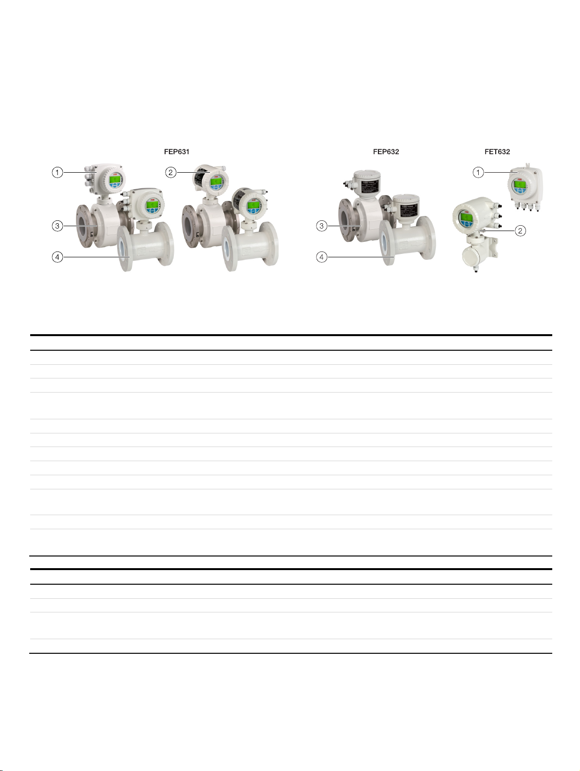
ProcessMaster
Integral mount design Remote mount design
1 Single-compartment transmitter housing
2 Dual-compartment transmitter housing
Figure 1: Designs
3 Flowmeter sensor, Design Level A (DN 3 to 2000)
4 Flowmeter sensor, Design Level B (DN 25 to 300)
Flowmeter sensor
Model ProcessMaster FEP631, FEP632, FET632
Housing Integral mount design, remote mount design
Measuring accuracy for liquids 0.4 % of the measured value, option for 0.3 % and 0.2 % of the measured value
Permissible measuring medium temperature
T
medium
Standard: −25 to 130 °C (−13 to 266 °F)
Option: −25 to 180 °C (−13 to 356 °F)
Minimum conductivity > 5 µS/cm, (20 µS/cm for demineralized water)
Nominal pressure rating PN 10 to 40; ASME CL 150, 300; JIS 5K, 10K, 20K
Nominal diameter DN 3 to 2000 (¹⁄₁₀ to 80 in)
Process connection Flange in accordance with DIN, ASME, JIS, AS2129 table D, E
Materials process connection Steel, cast iron, stainless steel
Lining material Hard rubber (DN 25 to 2000), soft rubber (DN 50 to 2000), PTFE (DN 10 to 600), PFA (DN 3 to 200),
ETFE (DN 25 to 600), Ceramic Carbide (DN 25 to 1000), Linatex® (DN 50 to 600)
Electrode material Stainless steel, Hastelloy B®, Hastelloy C®, platinum-iridium, tantalum, titanium, Double Layer, tungsten carbide
IP rating Integral mount design: IP 65 / IP 67, NEMA 4X
Remote mount design: IP 65 / IP 67 / IP 68 (sensor only), NEMA 4X
Approvals
Pressure Equipment Directive 2014/68/EU Conformity assessment in accordance with category III, fluid group 1
CRN (Canadian regulatory number) On request
Explosion protection (in preparation) ATEX / IECEx Zone 1, 2, 21, 22
Additional approvals At www.abb.com/flow or on request.
FM / cFM Cl 1 Div 1 (≤ DN 300), Cl 1 Div 2
Page 8
8 FEP630, FEH630 ELECTROMAGNETIC FLOWMETER | OI/FEP630/FEH630-EN REV. D
… 2 Design and function
… Overview
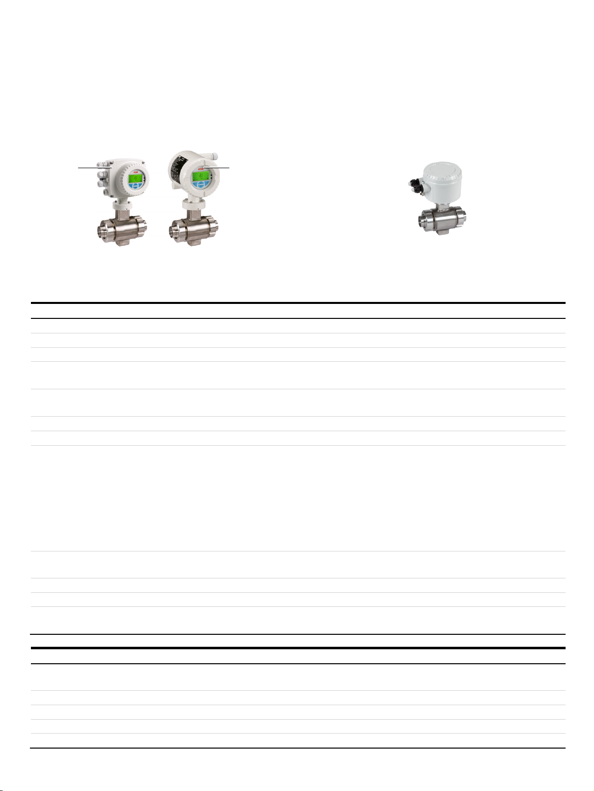
HygienicMaster
Integral mount design Remote mount design
FEH631 FEH632
1 2
G12161
1 Single-compartment transmitter housing
Figure 2: Designs (example, devices with variable process connections)
2 Dual-compartment transmitter housing
Flowmeter sensor
Model HygienicMaster FEH631, FEH632, FET632
Housing Integral mount design, remote mount design
Measuring accuracy for liquids 0.4 % of the measured value, option for 0.3 % and 0.2 % of the measured value
Permissible measuring medium
temperature T
medium
Standard: −25 to 130 °C (−13 to 266 °F), DN 1 to 2 limited to a maximum of 120 °C (248 °F)
Option: −25 to 180 °C (−13 to 356 °F), flange devices only
Minimum conductivity > 5 µS/cm, (> 20 µS/cm for demineralized water)
> 20 µS/cm for nominal diameter DN 1 to 2 (¹⁄₂₅ to ¹⁄₁₂in)
Nominal pressure PN 10 to 40, ASME CL 150, 300, JIS 10K
Nominal diameter DN 1 to 100 (¹⁄₂₅ to 4 in)
Process connection Wafer type design:
Flange in accordance with DIN, ASME or JIS
Screwed connections for the food industry in accordance
with DIN 11851:
Welded spuds:
Tri-clamp in accordance with DIN 32676
Tri-clamp in accordance with ASME BPE:
External thread in acc. with ISO 228 / DIN 2999
DN 3 to 100 (¹⁄₁₀ to 4 in)
DN 3 to 100 (¹⁄₁₀ to 4 in), PN 10 to 40
DN 3 to 100 (¹⁄₁₀ to 4 in), PN 10 to 40
DN 3 to 100 (¹⁄₁₀ to 4 in), PN 10 to 40
DN 3 to 100 (¹⁄₁₀ to 4 in), PN 10 to 16
DN 3 to 100 (¹⁄₁₀ to 4 in), PN 10
DN 3 to 25 (¹⁄₁₀ to 1 in), PN 16
Materials process connection Flange design: stainless steel, variable process connections: 1.4404;
devices with nominal diameter DN 1 to 2 (¹⁄₂₅ to ¹⁄₁₂ in): stainless steel 1.4571 (AISI 316 Ti), PVC, POM
Lining material PFA [vacuum-tight, from DN 3 (¹⁄₁₀ in)], PEEK [DN 1 to 2 (¹⁄₂₅ to ¹⁄₁₂ in)]
Electrode material Stainless steel 1.4571 (AISI 316Ti), 1.4539 [904L], Hastelloy B®, Hastelloy C®, platinum-iridium, tantalum, titanium
IP rating Integral mount design: IP 65 / IP 67, NEMA 4X
Remote mount design: IP 65 / IP 67 / IP 68 (sensor only), NEMA 4X
Approvals
Pressure Equipment Directive
2014/68/EU
CRN (Canadian regulatory number) On request
Hygiene design approvals 3A, FDA-approved materials
Explosion protection (in preparation) ATEX / IECEx Zone 1, 2, 21, 22; FM / cFM Cl 1 Div. 1, Cl 1 Div. 2
Additional approvals At www.abb.com/flow or on request.
Conformity assessment in accordance with category III, fluid group 1
Page 9
FEP630, FEH630 ELECTROMAGNETIC FLOWMETER | OI/FEP630/FEH630-EN REV. D 9
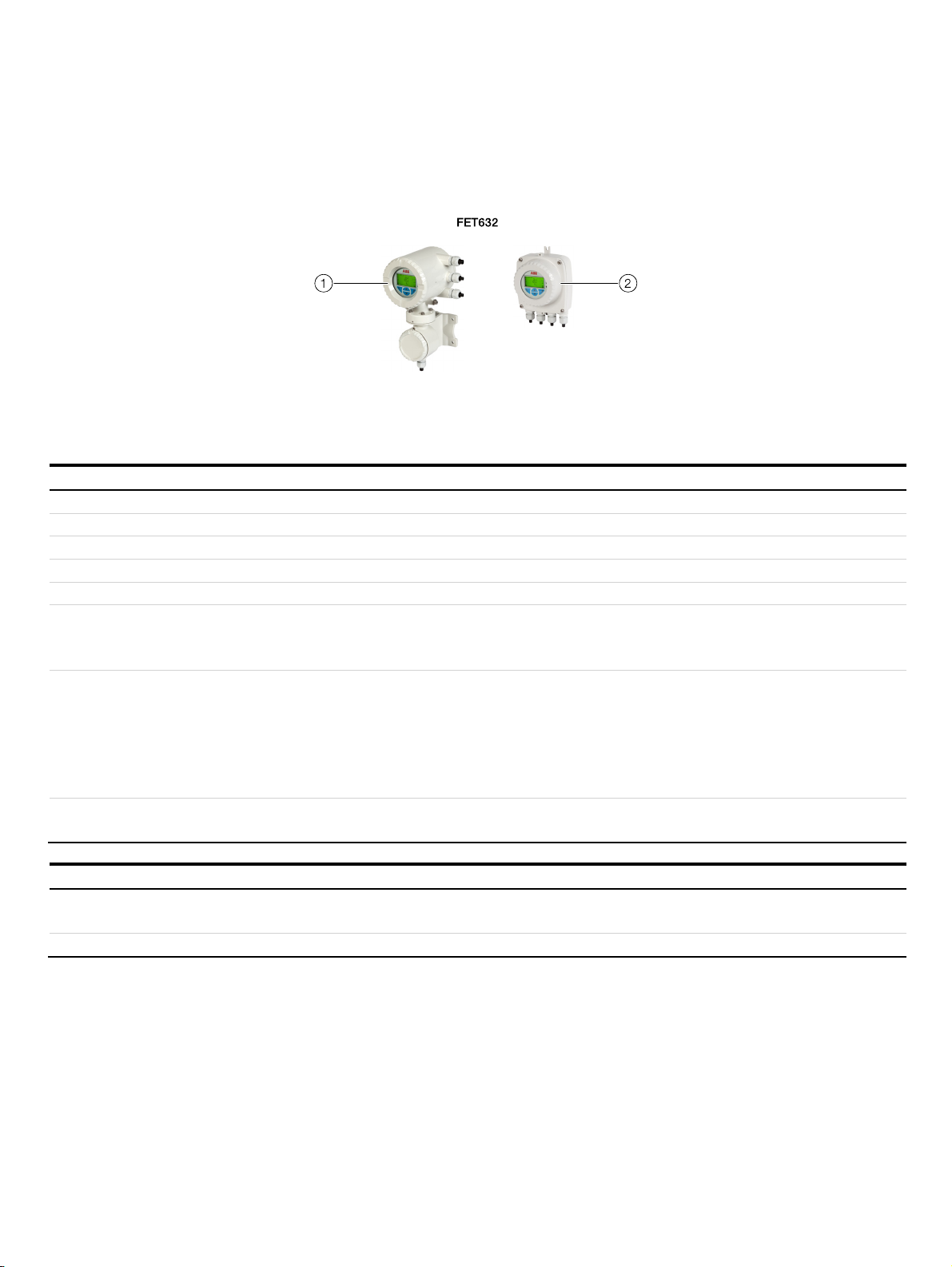
Transmitter
1 Dual-compartment transmitter housing
Figure 3: Designs
2 Single-compartment transmitter housing
Transmitter
Model FET632
Housing Integral mount design, remote mount design
IP rating IP 65 / IP 67 / NEMA 4X
Cable length Maximum 200 m (656 ft), remote mount design only
Power supply 100 to 240 V AC (−15 / +10 %) 50 / 60 Hz, 16.8 to 30 V DC
Outputs Current output: 4 to 20 mA active or passive (can be configured on-site)
Digital output 1: passive, configurable as pulse, frequency or switch output
Digital output 2: passive, configurable as pulse or switch output
Additional outputs The transmitter has two slots which can be used to insert plug-in cards to extend the outputs.
The following plug-in cards are available:
• Current output (passive)
• Digital output (passive)
• Digital input (passive):
• 24 V DC power supply for active outputs
Communication Standard: HART® 7.1
Option: PROFIBUS DP® / Modbus®
Approvals
Explosion protection (in preparation) ATEX / IECEx Zone 1, 2, 21, 22
Additional approvals At www.abb.com/flow or on request.
Change from one to two columns
FM / cFM Cl 1 Div 1, Cl 1 Div 2
Page 10

10 FEP630, FEH630 ELECTROMAGNETIC FLOWMETER | OI/FEP630/FEH630-EN REV. D
… 2 Design and function
Model variants
ProcessMaster / HygienicMaster is available in two product
series.
• FEP610 / FEH610 with base functionality
• FEP630 / FEH630 with extended functions and options
Characteristics / Functions ProcessMaster HygienicMaster
Measuring accuracy
0.4 % (option 0.2 %) of measured
value
0.5 % of measured value
Explosion protection
Option with approval for
potentially explosive atmosphere
Optional diagnosis functions
Detecting gas bubbles,
conductivity monitoring,
temperature monitoring
Grounding check
With noise check functions
Detection of partially filled pipe
With partial fill electrode
Liner and electrode material
optional
Ceramic carbide liner, tungsten
carbide electrodes, double-layer
electrodes
Batch functions
Presetting counter, overrun
correction, external start/stop,
batch end contact
Optional nominal diameter
DN 1 to DN 2
Fieldbus
PROFIBUS DP®, Modbus®
Verification
Optional
FEP610 FEP630 FEH610 FEH630
–
–
–
–
–
–
– – –
–
–
–
–
–
– –
– –
–
–
–
Integral mount design
For devices with an integral mount design, the transmitter and
flowmeter sensor form a single mechanical unit.
Remote mount design
For devices with a remote mount design, the transmitter and
flowmeter sensor are mounted in separate locations.
The electrical connection between the transmitter and the
flowmeter sensor is provided by a signal cable.
A maximum signal cable length of 200 m (656 ft) is possible.
Notes on the ProcessMaster
The flowmeter sensor of the ProcessMaster is available in two
designs, which are distinguished by the design level (A / B).
Notes on the transmitter housing
The transmitter is available in two housing designs:
• Single-compartment housing:
In the single-compartment housing, the electronics
chamber and the connection chamber in the transmitter
are not separated from each other.
• Dual-compartment housing:
In the dual-compartment housing, the electronics
chamber and the connection chamber in the transmitter
are separated from each other.
Page 11

FEP630, FEH630 ELECTROMAGNETIC FLOWMETER | OI/FEP630/FEH630-EN REV. D 11
Measuring principle
Measurements performed by the electromagnetic flowmeter are
based on Faraday’s law of induction. A voltage is generated in a
conductor when it moves through a magnetic field.
1 Magnet coil
2 Measuring tube in electrode plane
Figure 4: Electromagnetic flowmeter diagram
3 Measuring electrode
2
D
1
U1 Measuring span
B Magnetic induction
D Electrode spacing
vDBU
~
qv
v
4
v Average flow velocity
qv Volume flow rate
qvU
~
1
With the device-relevant application of this measuring principle,
a conductive measuring medium flows through a tube in which a
magnetic field is generated perpendicular to the flow direction
(see Figure 4).
The voltage induced in the measuring medium is tapped by two
diametrically opposed electrodes. This measurement voltage is
proportional to the magnetic induction, the electrode spacing
and the average medium velocity v.
Taking into account that the magnetic induction and the
electrode spacing are constant values results in a proportion
between the measurement voltage U
and the average medium
1
velocity.
From the calculation of the volume flow rate follows that the
measurement voltage is linear and proportional to the volume
flow rate
The induced voltage is converted by the transmitter to
standardized, analog and digital signals.
Page 12
12 FEP630, FEH630 ELECTROMAGNETIC FLOWMETER | OI/FEP630/FEH630-EN REV. D
3 Product identification
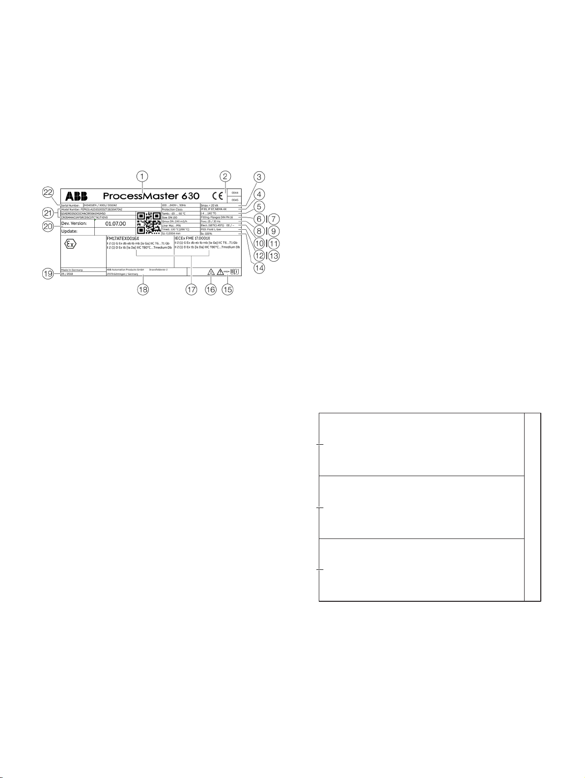
Name plate
Note
The name plates displayed are examples. The device
identification plates affixed to the device can differ from this
representation.
1 Type designation
2 CE mark
3 Power supply
4 IP rating in accordance with
EN 60529
5 T
6 Nominal diameter
7 Process connection / pressure
8 Calibration value Q
9 Excitation frequency
0 Liner material
k Electrode material /
l T
m Label indicating whether the
Figure 5: Name plate (example)
= maximum permissible
amb
ambient temperature
rating
DN
max
Supplementary information:
EE = grounding electrodes,
TFE = partial filling electrode
= maximum permissible
med
measuring medium
temperature
pressure equipment is subject
to the Pressure Equipment
Directive.
n Calibration value Sz (zero point), Ss
(range)
o ‘Follow operating instruction’
symbol
p ‘Caution hot surface’ symbol
q Ex marking in accordance with
ATEX / IECEx (example)
r Manufacturer address
s Year of manufacture
t Software version
u Model number (for more detailed
information about the technical
design, refer to the data sheet or
the order confirmation)
v Order number / Serial number for
identification by the manufacturer
Note
Devices with 3A approval SIL are labeled with an additional plate.
Marking in accordance with Pressure Equipment Directive
2014/68/EU
Information on the relevant fluid group (Figure 5, Position
• PED: Fluid 1, Gas
Fluid group 1 = hazardous fluids, liquid, gaseous. (PED =
PressureEquipmentDirective).
• SEP
If the pressure equipment is not in the scope of the
Pressure Equipment Directive, it is classified in
accordance with SEP = Sound Engineering Practice
(‘sound engineering practice’) in accordance with Art. 4
para. 3 of the Pressure Equipment Directive.
If there is no such information at all, there is no compliance with
the requirements of the Pressure Equipment Directive.
Water supplies and connected equipment accessories are
classed as an exception in accordance with guideline 1/16 of
Art. 1 Para. 3.2 of the Pressure Equipment Directive.
Additional warning plate
Devices which are approved for use in potentially explosive
atmospheres have an additional warning plate.
Warnung!
Gefahr durch elektrostatische Entladung
Warning!
1
Danger by electrostatic unloading
AVERTISSEMENT!
Risque de d charge électrostatique
Warnung!
Nicht öffnen, wenn eine explosionsfähige Athmosphäre vorhanden ist.
Warning!
2
DO NOT OPEN WHEN AN EXLPOSIVE ATMOSPHERE IS PRESENT
AVERTISSEMENT!
Ne pas ouvrir en presence d'une atmosphere explosive
Achtung:
Heisse Oberfläche
Warning:
3
Hot Surface
Attention:
Surface tres chaude
1 WARNING - Danger due to
electrostatic discharge.
2 WARNING - Do not open if an
explosive atmosphere is
present.
Figure 6: Additional warning plate
3 WARNING - Hot surface.
4 Thread for cable glands
m):
4
Cable entries: M20 x 1,5
G12174
Page 13
FEP630, FEH630 ELECTROMAGNETIC FLOWMETER | OI/FEP630/FEH630-EN REV. D 13
4 Transport and storage
Inspection
Check the devices immediately after unpacking for possible
damage that may have occurred from improper transport.
Details of any damage that has occurred in transit must be
recorded on the transport documents.
All claims for damages must be submitted to the shipper
without delay and before installation.
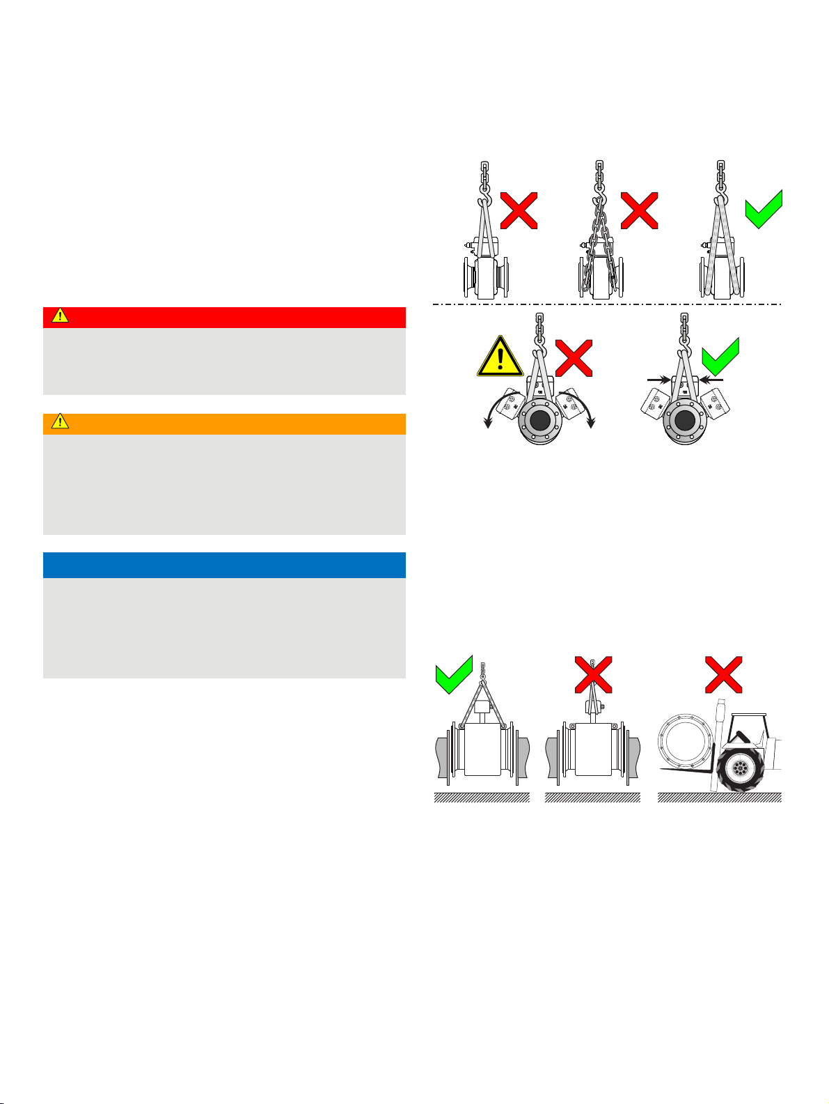
Transport
DANGER
Life-threatening danger due to suspended loads.
In the case of suspended loads, a danger of the load falling
exists.
• Standing under suspended loads is prohibited.
WARNING
Risk of injury due to device slipping.
The device's center of gravity may be higher than the harness
suspension points.
• Make sure that the device does not slip or turn during
transport.
• Support the device laterally during transport.
NOTICE
Potential damage to the device!
The protection plates or protection caps mounted at the
process connections on devices with PTFE / PFA liners may
only be removed immediately before installation.
• To prevent possible leakage, make sure that the liner on
the flange is not cut or damaged.
G12034
Figure 7: Transport instructions - ≤ DN 450
Flange devices ≤ DN 450
• Use carrying straps to transport flange designs smaller than
DN 450.
• Wrap the carrying straps around both process connections
when lifting the device.
• Chains should not be used, since these may damage the
housing.
Flange devices > DN 450
G10645
Figure 8: Transport instructions - > DN 450
• Using a forklift to transport flange device can dent the
housing.
• Flange devices must not be lifted by the center of the
housing when using a forklift for transport.
• Flange devices must not be lifted by the terminal box or by
the center of the housing.
• Only the transport lugs fitted to the device can be used to lift
the device and insert it into the piping.
Page 14

14 FEP630, FEH630 ELECTROMAGNETIC FLOWMETER | OI/FEP630/FEH630-EN REV. D
… 4 Transport and storage
Storing the device
Bear the following points in mind when storing devices:
• Store the device in its original packaging in a dry and
dust-free location.
• Observe the permitted ambient conditions for transport
and storage.
• Avoid storing the device in direct sunlight.
• In principle, the devices may be stored for an unlimited
period. However, the warranty conditions stipulated in
the order confirmation of the supplier apply.
Temperature data
Storage temperature range
−40 to 70 °C (−40 to 158 °F)
The ambient conditions for the transport and storage of the
device correspond to the ambient conditions for operation of
the device.
Adhere to the device data sheet!
Returning devices
For the return of devices, follow the instructions in Repair on
page 123.
Page 15

FEP630, FEH630 ELECTROMAGNETIC FLOWMETER | OI/FEP630/FEH630-EN REV. D 15
5 Installation
Safety instructions
WARNING
Risk of injury due to process conditions.
The process conditions, for example high pressures and
temperatures, toxic and aggressive measuring media, can
give rise to hazards when working on the device.
• Before working on the device, make sure that the process
conditions do not pose any hazards.
• If necessary, wear suited personal protective equipment
when working on the device.
• Depressurize and empty the device / piping, allow to cool
and purge if necessary.
WARNING
Risk of injury due to live parts!
When the housing is open, contact protection is not provided
and EMC protection is limited.
• Before opening the housing, switch off the power supply.
Use in Potentially Explosive Atmospheres
DANGER
Danger of explosion if the device is operated with the
transmitter housing or terminal box open!
While using the device in potentially explosive atmospheres
before opening the transmitter housing or the terminal box,
note the following points:
• A valid fire permit must be present.
• Make sure that no flammable or hazardous atmospheres
are present.
Note
• An additional document with Ex safety instructions is
available for measuring systems that are used in potentially
explosive atmospheres.
• Ex safety instructions are an integral part of this manual. As
a result, it is crucial that the installation guidelines and
connection values it lists are also observed.
The icon on the name plate indicates
the following:
Installation conditions
General
The following points must be observed during installation:
• The flow direction must correspond to the marking, if
present
• The maximum torque for all flange screws must be
complied with
• Secure flange screws and nuts against pipe vibration.
• The devices must be installed without mechanical tension
(torsion, bending)
• Install flange devices / wafer-type devices with plane
parallel counterflanges and use appropriate gaskets only
• Use gaskets made from a material that is compatible
with the measuring medium and measuring medium
temperature.
• Gaskets must not extend into the flow area, since
possible turbulence could influence the accuracy of the
device
• The piping may not exert any inadmissible forces or
torques on the device.
• Make sure that the temperature limits are not up-scaled
during operation of the device.
• Vacuum shocks in the piping should be avoided to
prevent damage to the liners (PTFE liner). Vacuum shocks
can destroy the device.
• Do not remove the sealing plugs in the cable glands until
you are ready to install the electrical cable
• Make sure the gaskets for the housing cover are seated
correctly. Carefully seal the cover. Tighten the cover
fittings
• The transmitter with a remote mount design must be
installed at a largely vibration-free location
• Do not expose the transmitter and sensor to direct
sunlight. Provide appropriate sun protection as necessary
If necessary, provide a suited means of sun protection.
• When installing the transmitter in a control cabinet, make
sure adequate cooling is provided
Devices with extended diagnostic functions
For devices with extended diagnostic functions different
installation conditions may be valid.
For additional information, see Extended diagnostic functions
on page 118.
Page 16
16 FEP630, FEH630 ELECTROMAGNETIC FLOWMETER | OI/FEP630/FEH630-EN REV. D
… 5 Installation
… Installation conditions
Brackets
NOTICE
Potential damage to the device!
Improper support for the device may result in a deformed
housing and damage to internal magnetic coils.
• Place the supports at the edge of the sensor housing (see
arrows in Figure 9).
Figure 9: Support for nominal diameters larger than DN 400
Devices with nominal diameters larger than DN 400 must be
mounted on a sufficiently strong foundation with support.
Gaskets
The following points must be observed when installing gaskets:
• To achieve the best results, make sure that the gaskets
and meter tube fit concentrically.
• To make sure that the flow profile is not distorted, the
gaskets may not intrude in the piping cross-section.
• The use of graphite with the flange or process connection
gaskets is prohibited. This is because, in some instances,
an electrically conductive coating may form on the inside
of the meter tube.
Devices with hard rubber or soft rubber liner
• Devices with a hard / soft rubber liner always require
additional gaskets
• ABB recommends using gaskets made from rubber or
rubber-like sealing materials
• When selecting the gaskets, make sure that the tightening
torques specified in chapter Torque information on page 144
are not up-scaled.
Devices with a PTFE, PFA or ETFE liner
• In principle, devices with a PTFE, PFA or ETFE liner do not
require additional gaskets.
Devices with a wafer-type design
1 2 3 3
1 Threaded rod
2 Nut with washer
Figure 10: Assembly set for wafer type assembly (example)
For devices with a wafer-type design, ABB offers an installation
set as an accessory that comprises threaded rods, nuts, washers
and centering sleeves for installation.
Flow direction
Figure 11: Flow direction
The device measures the flow rate in both flow directions.
Forward flow is the factory setting, as shown in Figure 11.
3 Centering sleeve
G12060
Page 17
FEP630, FEH630 ELECTROMAGNETIC FLOWMETER | OI/FEP630/FEH630-EN REV. D 17
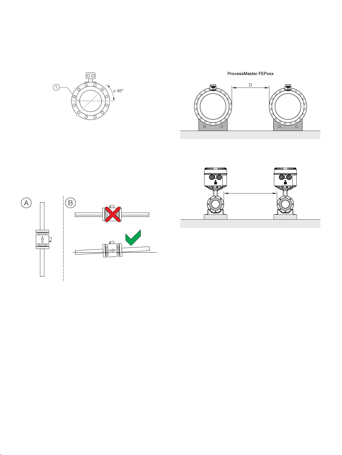
Electrode axis
1 Electrode axis
Figure 12: Orientation of the electrode axis
The flowmeter sensor should be mounted in the piping in such a
manner that the electrode axis is oriented as horizontally as
possible.
A maximum deviation of 45° from the horizontal position is
permissible.
Mounting position
Minimum spacing of the devices
Spacing D: ≥ 1.0 m (3.3 ft) for Design Level ‘A’,
≥ 0.7 m (2.3 ft) for Design Level ‘B’
HygienicMaster xxxFEH
D
Figure 13: Mounting position
A Vertical installation for measuring abrasive materials,
preferably with flow in upward direction.
B For a horizontal installation, the meter tube must always be
completely filled with the measuring medium.
Provide for a slight incline of the connection for degassing.
Note
For hygienic applications, the vertical mounting position is
preferred.
For a horizontal mounting position, make sure that the sensor is
installed to be self-draining.
Spacing D: ≥ 1.0 m (≥ 3.3 ft)
Figure 14: Minimum spacing
• In order to prevent the devices from interfering with each
other, a minimum distance as presented in Minimum spacing
of the devices must be maintained between the devices.
• The sensor must not be operated in the vicinity of powerful
electromagnetic fields, e.g., motors, pumps, transformers,
etc. A minimum spacing of approx. 1 m (3.28 ft) must be
maintained.
• For installation on or to steel parts (e.g. steel brackets), a
minimum spacing of 100 mm (3.94 in
) must be maintained.
These values have been calculated on the basis of IEC 801-2
or IEC TC77B
G12063
Page 18
18 FEP630, FEH630 ELECTROMAGNETIC FLOWMETER | OI/FEP630/FEH630-EN REV. D
… 5 Installation
… Installation conditions
Grounding
The flowmeter sensor must be connected to ground potential.
For technical reasons, this potential must be identical to the
potential of the measuring medium.
In piping made of plastic or with insulating liner, grounding of
the measuring medium is done by installing grounding plates.
If stray potential is present in the piping, adding a grounding
plate on both ends of the flowmeter sensor is recommended.
Sensor insulation
1 Insulation
Figure 15: Insulation of the flowmeter sensor
In the high temperature design, the flowmeter sensor can be
completely thermally insulated. After the unit is installed, the
piping and sensor must be insulated in accordance with the
figure.
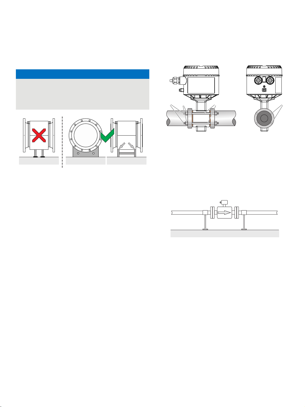
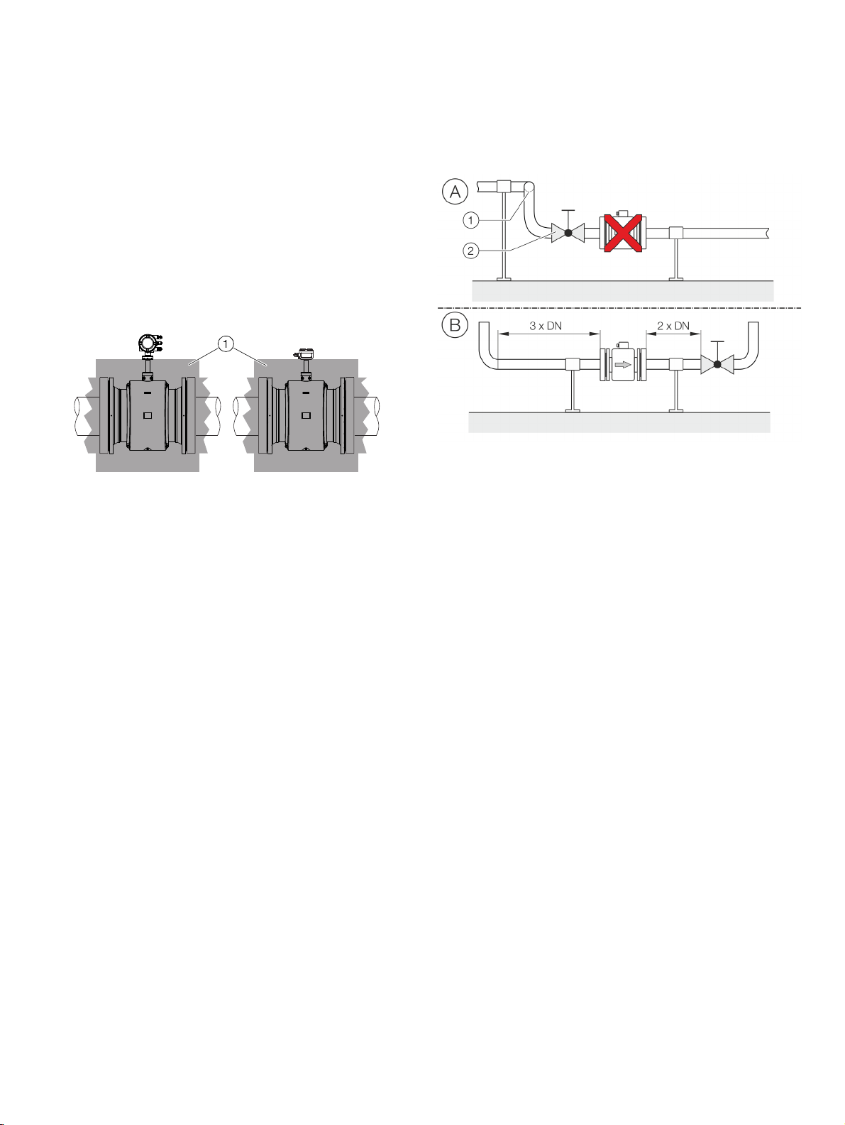
Inlet and outlet sections
1 Double manifold 2 Turn-off device
Figure 16: Inlet and outlet section, turn-off devices
The measuring principle is independent of the flow profile as
long as standing eddies do not extend into the measured value
formation, such as may for example occur after double
manifolds, in the event of tangential inflow, or where half-open
gate valves are located upstream of the sensor. In such cases,
measures must be put in place to normalize the flow profile.
A Do not install fittings, manifolds, valves, etc., right before the
flowmeter sensor.
B Inlet / outlet sections: length of the straight piping upstream
and downstream on the sensor.
Experience has shown that, in most installations, straight
inlet sections 3 × DN long and straight outlet sections 2 × DN
long are sufficient (DN = nominal diameter of the flowmeter
sensor).
For test stands, the reference conditions of 10 × DN straight
inlet and 5 × DN straight outlet must be provided, in
accordance with EN 29104 / ISO 9104.
Valves or other turn-off devices should be installed in the
outlet section.
Valve flaps must be installed so that the valve damper plate
does not extend into the flowmeter sensor.
Page 19
FEP630, FEH630 ELECTROMAGNETIC FLOWMETER | OI/FEP630/FEH630-EN REV. D 19
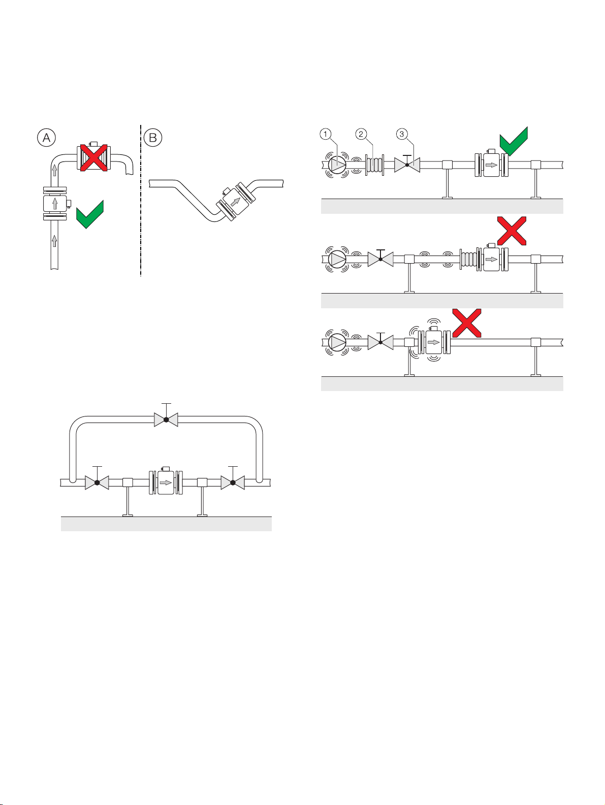
Free inlet or outlet
Figure 17: Free inflow and outflow
A For a free outflow, do not install flowmeter at the highest
point of the piping or on its outflow side, since the
measuring tube may run empty, creating air bubbles.
B For free inflow/outflow, provide an invert to make sure that
the piping is always full
Mounting with heavily contaminated measuring media
Mounting with pipe vibration
1 Pump
2 Damping device
3 Turn-off device
Figure 18: Bypass line
For strongly contaminated measuring media, a bypass line in
accordance with the figure is recommended so that operation of
the system can continue to run without interruption during
mechanical cleaning.
Figure 19: Vibration damping
If pipe vibration occurs, it needs to be damped using damping
devices.
The damping devices must be installed outside the support
section and outside of the piping section between the turn-off
devices.
Avoid connecting damping devices directly to the flowmeter
sensor.
Page 20
20 FEP630, FEH630 ELECTROMAGNETIC FLOWMETER | OI/FEP630/FEH630-EN REV. D
… 5 Installation
… Installation conditions
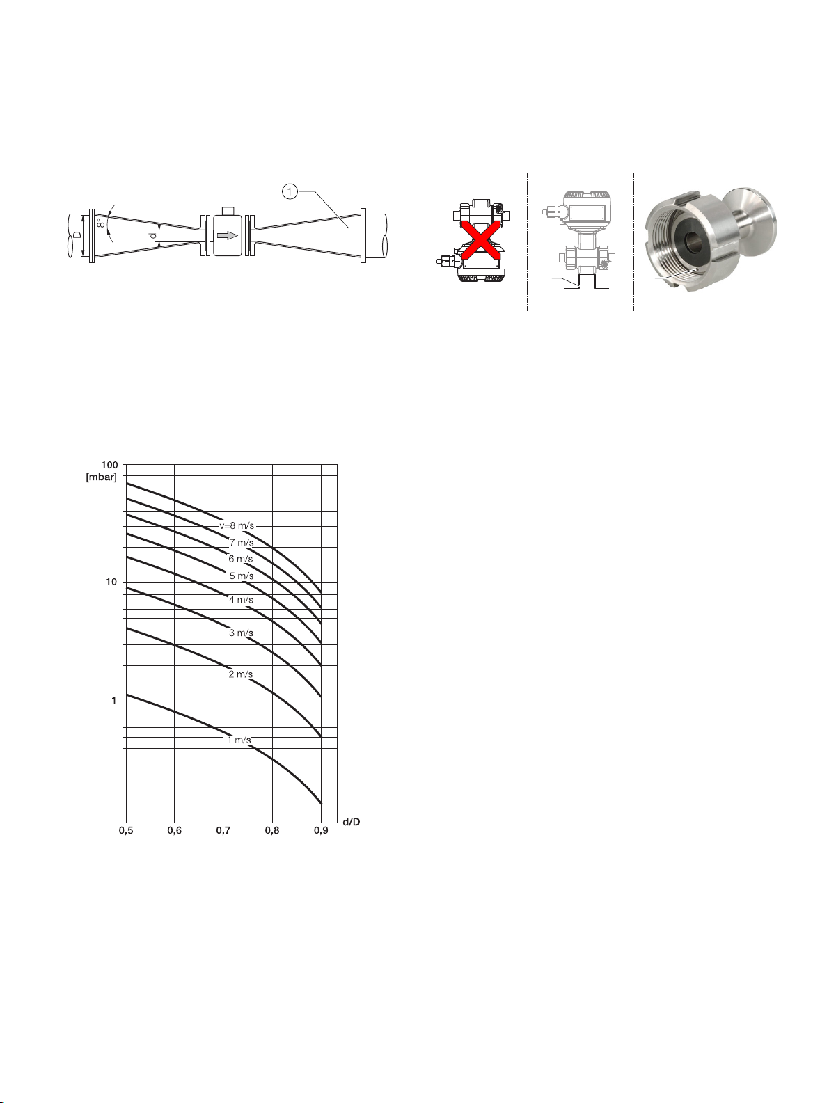
Installation in piping with larger nominal diameter
1 Reducer
Figure 20: Using reducers
Determine the resulting pressure loss when using reducers:
1. Determine diameter ratios d/D.
2. .Determine the flow velocity based on the flow rate
nomogram (Figure 21).
3. Read the pressure loss on the Y-axis in Figure 21.
Installation in 3A compliant installations
AB C
1 Angel bracket 2 Leakage hole
Figure 22: 3A compliant installation
Please observe the following points:
A Do not install the device vertically with the terminal box
or transmitter housing pointing downward.
B The ‘angel bracket’ option is not 3A compliant.
C Please make sure that the leakage hole of the process
connection is located at the lowest point of the installed
device.
• A vertical mounting position is preferred. For a horizontal
mounting position, make sure that the sensor is installed
to be self-draining.
• Make sure that the cover of terminal box and / or
transmitter housing is properly sealed. There can be no
gaps between the housing and the cover.
Only devices with the following process connections fulfill 3A
compliance.
• Welded spuds
• Tri-clamp
1 2
G12016
Figure 21: Flow rate nomogram for flange transition piece at α/2 = 8°
Page 21

FEP630, FEH630 ELECTROMAGNETIC FLOWMETER | OI/FEP630/FEH630-EN REV. D 21
Installing the sensor
NOTICE
Damage to the device
Damage to the device due to improper assembly.
• The use of graphite with the flange or process connection
gaskets is prohibited. This is because, in some instances,
an electrically conductive coating may form on the inside
of the meter tube.
• Vacuum shocks in the piping should be avoided to prevent
damage to the liners (PTFE liner). Vacuum shocks can
destroy the device.
The flowmeter sensor can be installed at any location in the
piping while taking the installation conditions into account.
1. Remove protective plates, if present, to the right and left of
the meter tube. To prevent possible leakage, make sure that
the liner on the flange is not cut or damaged.
2. Position the flowmeter sensor plane parallel and centered
between the piping.
3. Install gaskets between the surfaces, see Gaskets on
page 16.
Note
For achieve the best results, ensure the gaskets fit concentrically
with the meter tube
To ensure that the flow profile is not distorted, the gaskets must
not protrude into the piping.
4. Use the appropriate screws for the holes in accordance with
Torque information on page 144.
5. Slightly grease the threaded nuts.
6. Tighten the nuts in a crosswise manner as shown in the
figure. Observe the tightening torques in accordance with
Torque information on page 144!
First tighten the nuts to approx. 50 % of the maximum
torque, then to 80 %, and finally a third time to the maximum
torque. Do not exceed the max. torque.
1
3
8
4
4
Figure 23: Tightening sequence for the flange screws
2
1
6
5
3
7
2
G11726
Page 22
22 FEP630, FEH630 ELECTROMAGNETIC FLOWMETER | OI/FEP630/FEH630-EN REV. D
… 5 Installation
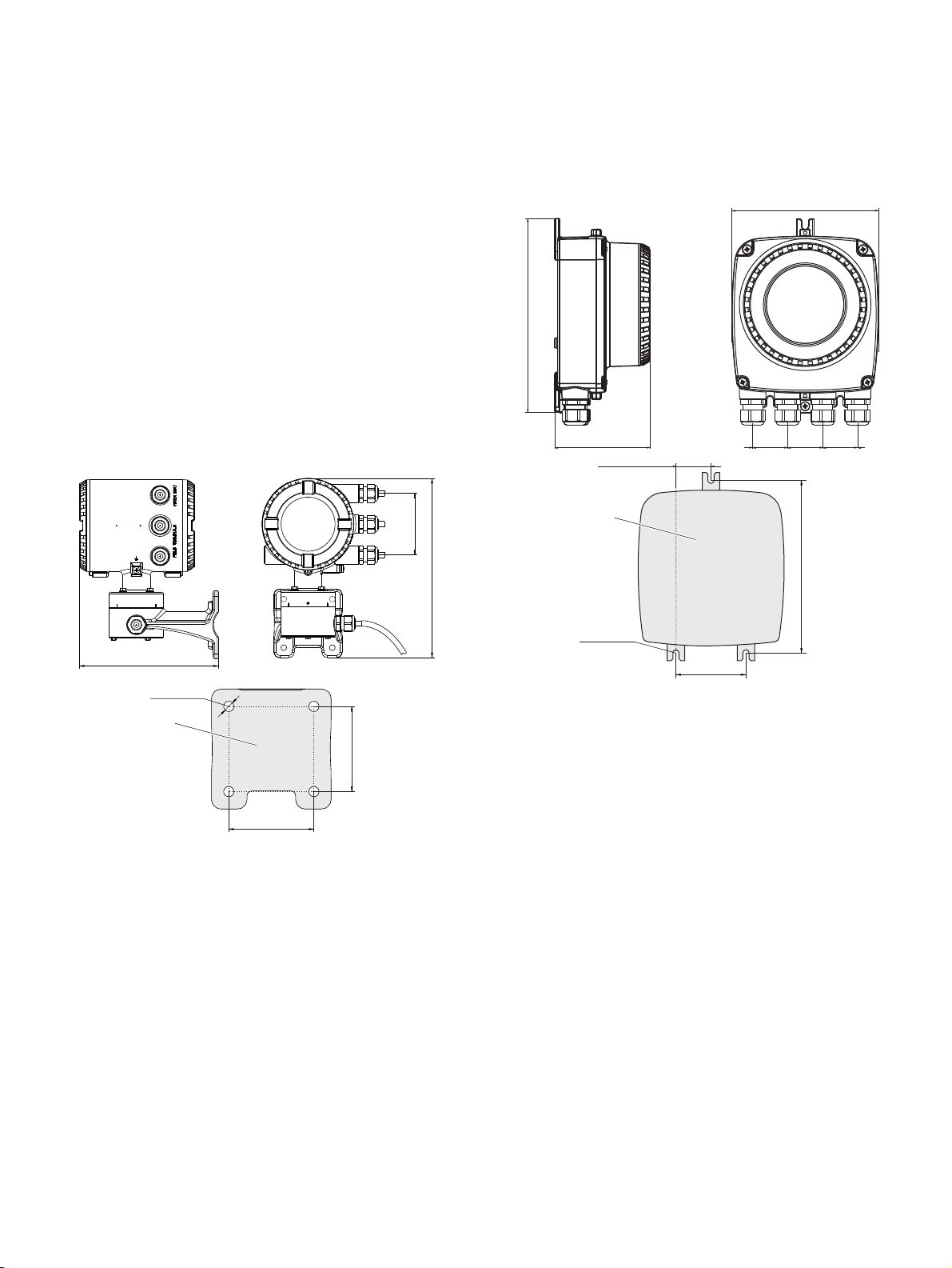
Installing the transmitter in the remote
mount design
When selecting a location for the transmitter, consider the
following points:
• Observe the information concerning maximum ambient
temperature and IP rating on the name plate
• The location must be mostly free from vibration.
• The location must not be exposed to direct sunlight. If
necessary provide a sun screen on site.
• Do not up-scale the maximum signal cable length
between the transmitter and the sensor.
1. Drill mounting holes at mounting location.
2. Attach transmitter securely to the mounting location using
suited fasteners for the base material.
2x45 = 90
(2x1.77 = 3.54)
150 (5.91)
200 (7.87)
98,1 (3.86)
36,5 (1.44)
36,3 (1.43)
1
205 (8.07)
Ø 7 (0.28)
1
71 (2.8)
1 Hole pattern for mounting holes
Figure 24: Mounting dimensions dual-compartment housing
71 (2.8)
G11567
262 (10.31)
Ø 6,4 (0.25)
72,5 (2.85)
1 Hole pattern for mounting holes
Figure 25: Mounting dimensions single-compartment housing
180 (7,1)
G11568
Page 23
FEP630, FEH630 ELECTROMAGNETIC FLOWMETER | OI/FEP630/FEH630-EN REV. D 23
Opening and closing the housing
DANGER
Danger of explosion if the device is operated with the
transmitter housing or terminal box open!
While using the device in potentially explosive atmospheres
before opening the transmitter housing or the terminal box,
note the following points:
• A valid fire permit must be present.
• Make sure that no flammable or hazardous atmospheres
are present.
WARNING
Risk of injury due to live parts!
When the housing is open, contact protection is not provided
and EMC protection is limited.
• Before opening the housing, switch off the power supply.
NOTICE
Potential adverse effect on the IP rating
• Check the O-ring gasket for damage and replace it if
necessary before closing the housing cover.
• Check that the O-ring gasket is properly seated when
closing the housing cover.
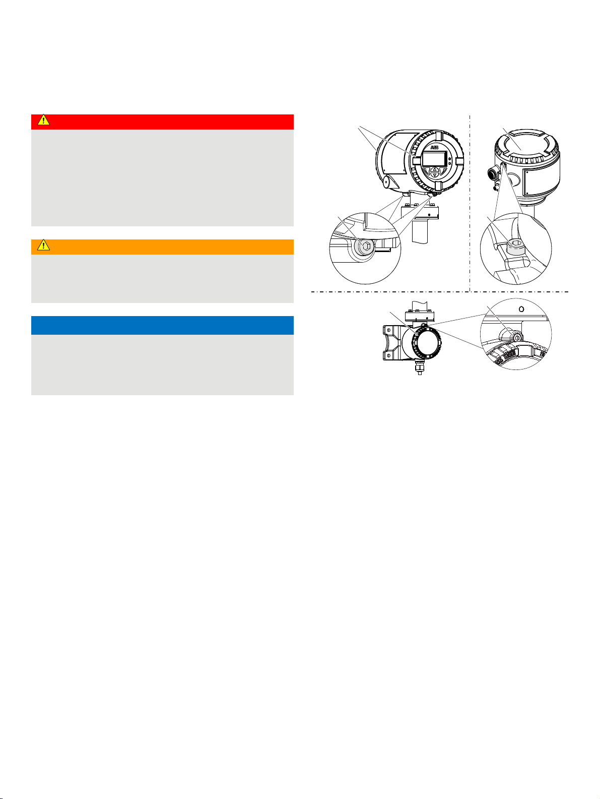
AB
C
A Integral mount design
B Remote mount design
Abbildung 26: Deckelsicherung (Beispiel)
Figure 27: Cover lock (example)
Open the housing:
Close the housing:
1 1
2
1
C Transmitter, terminal space,
1. Release the cover lock by screwing in the Allen screw
2. Unscrew cover
1. Screw on the cover
1.
1.
2
2
G11738-01
signal cable
2.
2. After closing the housing, lock the cover by unscrewing
the Allen screw 2.
Page 24
24 FEP630, FEH630 ELECTROMAGNETIC FLOWMETER | OI/FEP630/FEH630-EN REV. D
… 5 Installation
… Opening and closing the housing
NOTICE
Potential adverse effect on the IP rating
• Check the gasket for damage and replace it if necessary
before closing the housing cover.
• Check that the gaskets are properly seated when closing
the housing cover.
1
AA
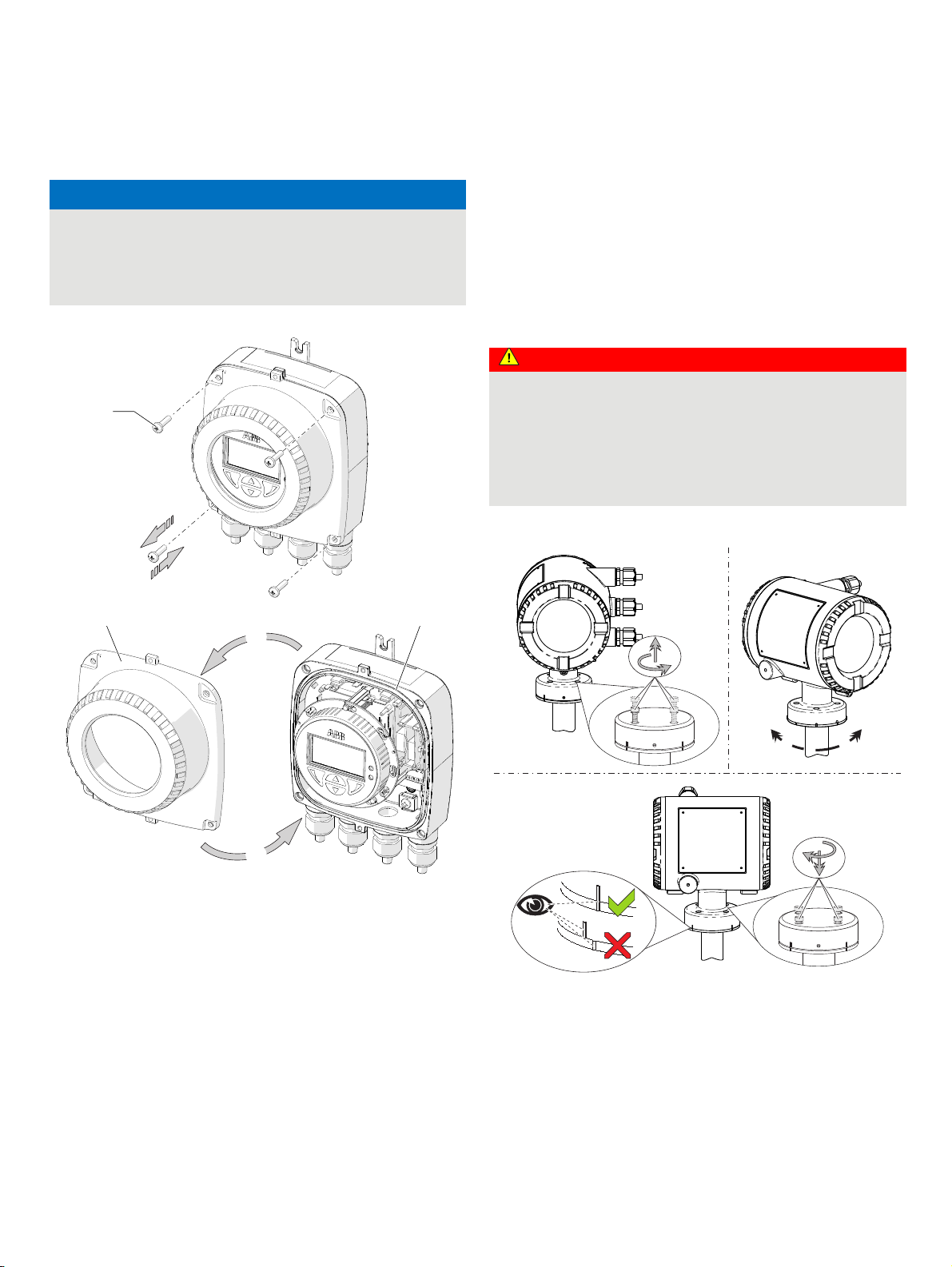
Adjusting the transmitter position
Depending on the installation position, the transmitter housing
or LCD display can be rotated to enable horizontal readings.
In addition, the display in the LCD indicator can be rotated by
180° using the parameter ‘Display Rotation’ (see Menu: Display
on page 87).
Transmitter housing
DANGER
Damaging the device carries a risk of explosion!
When the screws for the transmitter housing are loosened,
the explosion protection is suspended.
Tighten all screws prior to commissioning.
Never disconnect the transmitter housing from the sensor.
Only loosen the screws shown when rotating the transmitter
housing!
Rotate transmitter housing: Perform steps
A to C.
C
2 3
B
D
1 Cover screws
2 Transmitter housing cover
Figure 28: Open / close single-compartment housing
3 Gasket
Open transmitter housing: Perform steps
Close transmitter housing: Perform steps
A and B.
C and D.
G12149
AB
90°
90°
C
G11569
Figure 29: Rotate transmitter housing
Page 25

FEP630, FEH630 ELECTROMAGNETIC FLOWMETER | OI/FEP630/FEH630-EN REV. D 25
Rotate LCD indicator – dual-compartment housing
The LCD indicator can be rotated in three increments of 90°
each. To open and close the housing, refer to Opening and
closing the housing on page 23.
Turn the LCD indicator:
Perform steps
A to F.
Rotate LCD indicator – single-compartment housing
The LCD indicator can be rotated in three increments of 90°
each. To open and close the housing, refer to Opening and
closing the housing on page 23.
Turn the LCD indicator:
Perform steps
A to F.
Figure 30: Rotating the LCD indicator
Change from two to one column
Figure 31: Rotating the LCD indicator
Page 26
26 FEP630, FEH630 ELECTROMAGNETIC FLOWMETER | OI/FEP630/FEH630-EN REV. D
… 5 Installation
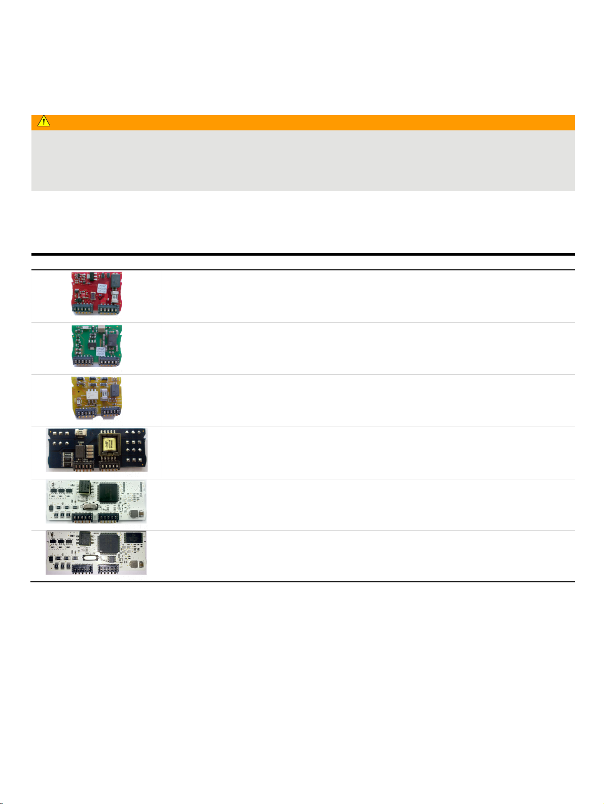
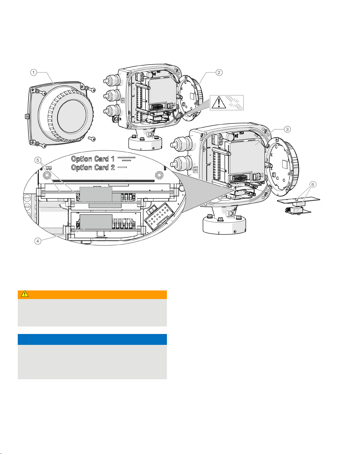
Installing the plug-in cards
WARNING
Loss of Ex Approval!
Loss of Ex Approval due to retrofitting of plug-in cards on devices for use in potentially explosive atmospheres.
• Devices for use in potentially explosive atmospheres may not be retrofitted with plug-in cards.
• If devices are to be used in potentially explosive atmospheres, the required plug-in cards must be specified when the order is
placed.
Optional plug-in cards
The transmitter has two slots (OC1, OC2) into which plug-in cards can be inserted to extend inputs and outputs. The slots are located
on the transmitter motherboard and can be accessed after removing the front housing cover.
Plug-in card Description Quantity*
Current output, 4 to 20 mA passive (red)
Order no.: 3KQZ400029U0100
Maximum of two plug-in cards
Passive digital output (green)
Order no.: 3KQZ400030U0100
Passive digital input (yellow)
Order no.: 3KQZ400032U0100
Loop power supply 24 V DC (blue)
Order no.: 3KQZ400031U0100
Modbus RTU RS485 (white)
Order no.: 3KQZ400028U0100
Profibus DP (white)
Order no.: 3KQZ400027U0100
* The ‘Number’ column indicates the maximum number of plug-in cards of the same type that can be used.
Maximum of one plug-in card
Maximum of one plug-in card
Maximum of one plug-in card
Maximum of one plug-in card
Maximum of one plug-in card
Page 27
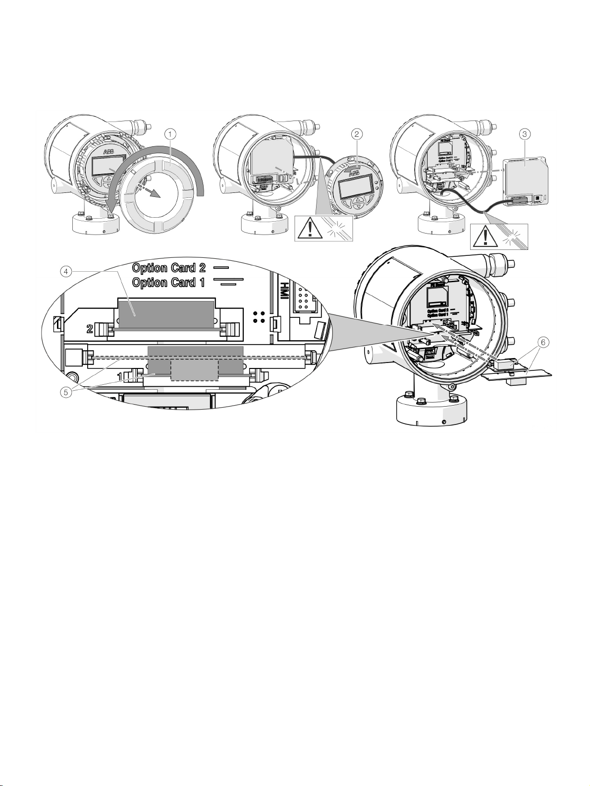
FEP630, FEH630 ELECTROMAGNETIC FLOWMETER | OI/FEP630/FEH630-EN REV. D 27
1 Cover
2 LCD indicator
3 Frontend board (FEB, with integral mount design only)
Figure 32: Installation of plug-in cards (example, dual-compartment housing)
4 Slot OC2
5 Slot OC1
6 Plug-in cards
Page 28
28 FEP630, FEH630 ELECTROMAGNETIC FLOWMETER | OI/FEP630/FEH630-EN REV. D
… 5 Installation
… Installing the plug-in cards
1 Cover
2 LCD indicator
3 Slot OC1
Figure 33: Installation of plug-in cards (example, single-compartment housing)
Change from one to two columns
WARNING
Risk of injury due to live parts!
When the housing is open, contact protection is not provided
and EMC protection is limited.
• Before opening the housing, switch off the power supply.
NOTICE
Damage to components!
The electronic components of the printed circuit board can be
damaged by static electricity (observe ESD guidelines).
• Make sure that the static electricity in your body is
discharged before touching electronic components.
4 Slot OC2
5 Plug-in cards
1. Switch off the power supply.
2. Unscrew / remove the cover.
3. Remove the LCD indicator. Ensure that the cable harness is
not damaged.
Insert the LCD indicator into the bracket
(only for single-compartment housings)
4. Remove frontend board (only in integral mount design and
dual-compartment housing). Ensure that the cable harness is
not damaged.
5. Insert the plug-in card in the corresponding slot and engage.
Ensure that the contacts are aligned correctly.
6. Attach the frontend board, insert the LCD indicator and
screw on / replace the cover.
7. Connect outputs V1 / V2 and V3 / V4 in accordance with
Electrical connections on page 29.
8. After powering up the power supply, configure the plug-in
card functions.
Page 29

FEP630, FEH630 ELECTROMAGNETIC FLOWMETER | OI/FEP630/FEH630-EN REV. D 29
6 Electrical connections
Safety instructions
WARNING
Risk of injury due to live parts.
Improper work on the electrical connections can result in
electric shock.
• Connect the device only with the power supply switched
off.
• Observe the applicable standards and regulations for the
electrical connection.
The electrical connection may only be established by authorized
specialist personnel and in accordance with the connection
diagrams.
The electrical connection information in this manual must be
observed; otherwise, the IP rating may be adversely affected.
Ground the measurement system according to requirements.
Use in Potentially Explosive Atmospheres
Note
• An additional document with Ex safety instructions is
available for measuring systems that are used in potentially
explosive atmospheres.
• Ex safety instructions are an integral part of this manual. As
a result, it is crucial that the installation guidelines and
connection values it lists are also observed.
The icon on the name plate indicates
the following:
Sensor grounding
General information on grounding
Observe the following items when grounding the device:
• For plastic piping or piping with insulating liner, the
ground is provided by the grounding plate or grounding
electrodes.
• When stray potentials are present, install a grounding
plate upstream and downstream of the sensor.
• For measurement-related reasons, the potential in the
station ground and in the piping should be identical.
Note
If the sensor is installed in plastic or earthenware pipelines, or in
pipelines with an insulating liner, compensating currents may
flow through the grounding electrode in special cases (e.g. with
corrosive measuring media, acids and bases)
In the long term, this may destroy the sensor, since the ground
electrode will in turn degrade electrochemically.
In these special cases, the connection to the ground must be
performed using grounding plates. Install a grounding plate
upstream and downstream of the device in this case.
Page 30
30 FEP630, FEH630 ELECTROMAGNETIC FLOWMETER | OI/FEP630/FEH630-EN REV. D
… 6 Electrical connections
… Sensor grounding
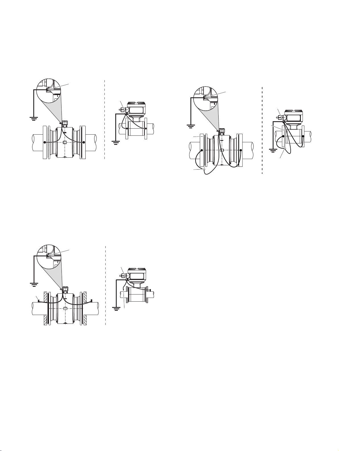
Metal pipe with fixed flanges
AB
A Flange design
B Wafer type design
Figure 34: Metal pipe, without liner (example)
1
1
G12021
1 Ground terminal
2
Use a copper wire [at least 2.5 mm
(14 AWG)] to establish the
connection between the ground terminal of the sensor, the
pipeline flanges and a suited grounding point in accordance with
the figure.
Metal pipe with loose flanges
AB
1
2
2
1
Plastic pipes, non-metallic pipes or pipes with insulating
liner
AB
3
2
A Flange design
B Wafer type design
1 Ground terminal
Figure 36: Plastic pipes, non-metallic pipes or pipes with insulating liner
For plastic pipes or pipes with insulating lining, the grounding of
the measuring medium is provided by the grounding plate as
shown in the figure below or via grounding electrodes that must
be installed in the device (option).
If grounding electrodes are used, the grounding plate is not
necessary.
1. Install the sensor with grounding plate in the piping.
2. Connect the terminal lug of the grounding plate and ground
connection on the sensor using the grounding strap.
3. Use a copper wire with at least 2.5 mm
establish a connection between the ground connection and a
suited grounding point.
1
1
3
2
2 Terminal lug
3 Grounding plate
2
(14 AWG)) to
G12023
G12022
A Flange design
B Wafer type design
Figure 35: Metal pipe, without liner (example)
1 Threaded bolts M6
2 Ground terminal
1. Solder the threaded bolts M6 to the piping and connect the
ground in accordance with the figure.
2
2. Use a copper wire [at least 2.5 mm
(14 AWG)] to establish
the connection between the ground terminal of the sensor
and a suited grounding point in accordance with the figure.
Page 31

FEP630, FEH630 ELECTROMAGNETIC FLOWMETER | OI/FEP630/FEH630-EN REV. D 31
Sensor type HygienicMaster
1
G12024
1 Process connection adapter
Figure 37: Sensor, type HygienicMaster
Perform grounding as shown in the figure. The measuring
medium is grounded via the process connection adapter, so
additional grounding is not required.
Grounding for devices with protective plates
The protection plates are used to protect the edges of the meter
tube liner, e.g. for abrasive media.
In addition, the protection plates function as a grounding plate.
• For plastic piping or piping with insulating liner, electrically
connect the protection plate in the same manner as a
grounding plate.
Grounding with conductive PTFE grounding plate
Grounding plates made of conductive PTFE are optionally
available for nominal diameter ranges of DN 10 to 250. These are
installed similar to conventional grounding plates.
Devices with extended diagnostic functions
For devices with extended diagnostic functions different
installation conditions may be valid.
For additional information, see Extended diagnostic functions
on page 118.
Installation and grounding in piping with cathodic
corrosion protection
The installation of electromagnetic flowmeters in systems with
cathodic corrosion protection must be made in compliance with
the corresponding system conditions. The following factors are
especially important:
1. Pipelines inside electrically conductive or insulating.
2. Piping consistently and widely on cathodic corrosion
protection potential. Or mixed systems with ranges on
cathodic corrosion protection potential and ranges on
functional ground potential.
• In the case of pipes free from stray current and
insulated on the inside with liner, the sensor should be
installed in the piping insulated with grounding plates
(upstream and downstream from the sensor). The
cathodic corrosion potential is bypassed around the
sensor. The grounding plates upstream and
downstream of the sensor are connected to
functional ground (Figure 38 / Figure 39).
• If the occurrence of external stray currents is to be
expected in piping with internal insulation (e.g. in the
case of long pipe sections in the vicinity of power
supply units), an uninsulated pipe of approx. ¼ × DN
of length should be provided upstream and
downstream of the sensor in order to deviate these
external stray currents away from the sensor
(Figure 40).
Page 32

32 FEP630, FEH630 ELECTROMAGNETIC FLOWMETER | OI/FEP630/FEH630-EN REV. D
… 6 Electrical connections
… Sensor grounding
Internally insulated piping with cathodic corrosion
potential
2 45
1066
3
1
8 7 6
1 Piping flange
2 Insulating plate
3 Gasket / insulating ring
4 Grounding plate
5 Insulating pipe
Figure 38: View Screw bolts
23
9
G11050
6 Flange
7 Liner
8 Insulation
9 Sensor
Install grounding plates on each side of the flowmeter sensor.
Insulate the grounding plates from the pipe flanges and connect
them to the flowmeter sensor and to functional ground.
The screw bolts for flange connections should be mounted with
insulation. The insulation plates and the insulation pipe are not
included in the delivery. They must be provided onsite by the
customer.
2
B
B
A Connection line corrosion
potential*
B Insulated screw bolts without
grounding plates
2
* ≥ 4 mm
Figure 39: sensor with grounding plate and functional ground
Cu, not included in the delivery, to be provided on-site
3
A
1 Insulated piping
2 Functional ground
3 Grounding plates
The corrosion protection potential must be diverted through a
connecting line
A away from the insulated installed sensor.
B
B
11
G11049
Page 33

FEP630, FEH630 ELECTROMAGNETIC FLOWMETER | OI/FEP630/FEH630-EN REV. D 33
Mixed system, piping with cathodic corrosion potential and
functional ground potential
Power supply
Note
• Adhere to the limit values of the power supply in accordance
with the information on the name plate.
• Observe the voltage drop for large cable lengths and small
conductor cross-sections. The voltage at the terminals of the
device may not down-scale the minimum value required in
accordance with the information on the name plate.
The power supply is connected to terminal L (phase), N (zero), or
B
2
3
121
B
1+, 2−, and PE.
A circuit breaker with a maximum rated current of 16 A must be
installed in the power supply line.
B
B
The wire cross-sectional area of the power supply cable and the
circuit breaker used must comply with VDE 0100 and must be
dimensioned in accordance with the current consumption of the
flowmeter measuring system. The cables must comply with
IEC 227 and/or IEC 245.
The circuit breaker must be located near the device and marked
as being associated with the device.
Connect the transmitter and sensor to functional earth.
A Connection line corrosion
potential*
B Insulated screw bolts without
grounding plates
2
* ≥ 4 mm
Figure 40: Sensor with functional ground
Cu, not included in the delivery, to be provided on-site
A
1 Insulated piping
2 Uninsulated metal piping
3 Functional ground
G11048
This mixed system has an insulated piping with corrosion
protection potential and an uninsulated metal pipe (L = ¼ × DN
sensor) with functional ground potential upstream and
downstream of the sensor.
Figure 40 shows the preferred installation for cathodic corrosion
protection.
Page 34

34 FEP630, FEH630 ELECTROMAGNETIC FLOWMETER | OI/FEP630/FEH630-EN REV. D
… 6 Electrical connections
Cable entries
The electrical connection is made via cable entries with a ½ inNPT or M20 × 1.5 thread.
Devices with a M20 × 1.5 or ½ in-NPT thread are equipped with
protective plugs.
The black protective plugs in the cable glands are intended to
provide protection during transport.
Any unused cable entries must be sealed with sealing plugs
before commissioning in accordance with the applicable
national standards.
• Observe maximum torque of 4.5 Nm (3.3 ft lb) when
tightening the M20 cable gland.
• Make sure that the cable outer dimension used will fit the
clamping range of the cable gland.
Connection via cable conduit
Installing the connection cables
General information on cable installation
Ensure that a drip loop (water trap) is used when installing the
connecting cables for the sensor.
When mounting the sensor vertically, position the cable entries
at the bottom.
If necessary, rotate the transmitter housing accordingly.
1
G12036
Figure 41: Installation set for cable conduit (Conduit)
NOTICE
Condensate formation in terminal box!
If the flowmeter sensor is permanently connected to cable
conduits, there is a possibility that moisture may get into the
terminal box as a result of condensate formation in the cable
conduit.
• Make sure that the cable conduits on the terminal box are
sealed.
An installation set for sealing the cable conduit is available
through order number 3KXF081300L0001 (Conduit).
1 Drip loop
Figure 42: Installation of the connection cable (example, integral mount design)
1
G12151
Page 35

FEP630, FEH630 ELECTROMAGNETIC FLOWMETER | OI/FEP630/FEH630-EN REV. D 35
Notes on signal cable installation
(only for remote mount design)
Observe the following points when installing the signal cable:
• The maximum signal cable length is 200 m (565 ft).
• Only used signal cable which is in accordance with the
following cable specifications.
• Avoid the vicinity of electrical equipment or switching
elements that can create stray fields, switching pulses
and induction. If this is not possible, run the signal /
magnet coil cable through a metal pipe and connect this
to the station ground.
• To shield against magnetic interspersion, the cable
contains outer shielding. This should be connected to the
SE clamp.
• Do not damage the sheathing of the cable during
installation.
The signal cable used for the connection of the transmitter and
sensor must fulfill at least the following technical specifications.
Cable specification
Impedance 100 to 200 Ω
Withstand voltage 120 V
Outer diameter 6 to 12 mm
(0.24 to 0.47 in)
Cable design Two wire pairs as a star-quad cable
Conductor cross-section Length-dependent
Shield Copper braid with
approximately 85 % coverage
Temperature range Depends on application.
Maximum signal cable length
0.25 mm2 (AWG 24) 50 m (164 ft)
0.34 mm2 (AWG 22) 100 m (328 ft)
0.5 mm2 (AWG 20) 150 m (492 ft)
0.75 mm2 (AWG 19) 200 m (656 ft)
Recommended cables
It is recommended to use an ABB signal cable with the order
number 3KQZ407123U0100 for standard applications.
The ABB signal cable fulfills the above-mentioned cable
specification and can be utilized unrestrictedly up to an ambient
temperature of T
For marine applications, an appropriate certified signal cable
must be used. ABB recommends the cable HELKAMA RFE-FRHF
2×2×0,75 QUAD 250V (HELKAMA order number 20522).
= 80 °C (176 °F).
amb
Connection with IP rating IP 68
1
G10171
1 Maximum flooding height 5 m (16.4 ft)
Figure 43: Maximum flooding height for IP 68 sensors
For sensors with IP rating IP 68, the maximum flooding height is
5 m (16.4 ft).
The supplied signal cable fulfills all the submersion
requirements.
The sensor is type-tested in accordance with EN 60529. Test
conditions:
14 days at a flooding height of 5 m 16.4 ft).
Page 36

36 FEP630, FEH630 ELECTROMAGNETIC FLOWMETER | OI/FEP630/FEH630-EN REV. D
… 6 Electrical connections
… Connection with IP rating IP 68
Electrical connection
NOTICE
Adverse effect on the IP rating IP 68
The IP rating IP 68 of the sensor may be adversely affected as
a result of damage to the signal cable.
• The sheathing of the signal cable must not be damaged.
1. Use the supplied signal cable to connect the sensor and the
transmitter.
2. Connect the signal cable in the terminal box of the sensor.
3. Route the cable from the terminal box to above the maximum
flooding height of 5 m (16.4 ft).
4. Tighten the cable gland.
5. Carefully seal the terminal box. Make sure the gasket for the
cover is seated properly.
Note
As an option, the sensor can be ordered with the signal cable
already connected to the sensor and the terminal box already
potted.
Potting the terminal box on-site
CAUTION
Danger to health!
The two-component potting compound is toxic – observe all
relevant safety measures!
Comply with the safety data sheet of the two-component
potting compound before preparations are started.
Risk notes:
• R20: Damaging to health when inhaled.
• R36/37/38: Irritates the eyes, respiratory organs and
the skin.
• R42/43: Sensitization through inhaling and skin
contact is possible.
Safety advice:
• S23: Do not inhale gas/smoke/humidity/aerosol.
• S24: Avoid contact with the skin.
• S37: Wear suited protective gloves.
• S63: In case of an accident due to inhaling: take the
injured person out into the fresh air to rest.
If the terminal box is to be potted subsequently on-site, a special
two-component potting compound can be ordered separately
(order no. D141B038U01). Potting is only possible if the sensor is
installed horizontally. Observe the following instructions during
work activity:
Change from two to one column
Preparation
• Complete the installation before potting in order to avoid
moisture penetration. Before starting, check all the
connections for correct fitting and stability
• Do not overfill the terminal box. Keep the potting compound
away from the O-ring and the gasket / groove (see
Figure 44).
• Prevent the two-component potting compound from
penetrating the cable conduit (Conduit) for an ½ in NPT
installation (if used).
Procedure
5
1
2
3
4
G12152
1 Packaging bag
2 Connection clamp
3 Two-component potting
compound
Figure 44: Terminal box sealing
1. Cut open the protective enclosure of the two-component
potting compound (see packing).
2. Remove the connection clamp of the potting compound.
3. Knead both components thoroughly until a good mix is
reached.
4. Cut open the bag at a corner. Perform work activity within
30 minutes.
5. Carefully fill the terminal box with the two-component
potting compound until the connection cable is covered.
6. Wait a few hours before closing the cover in order to allow
the compound to dry, and to release any possible gas.
7. Ensure that the packaging material and the drying bag are
disposed of in an environmentally sound manner.
4 Drying bag
5 Maximum fill level
Page 37

FEP630, FEH630 ELECTROMAGNETIC FLOWMETER | OI/FEP630/FEH630-EN REV. D 37
Pin assignment
A
1+ 2-
LN
HART
+
Uco
-
32 31
Oc2 Oc1
+
V3
V4 V1 V2
+
41
B
-
+
52
42
UFE
GND
51
AB
PE
≤ 200 m
( 656 ft)≤
UFE
GND
AB
B
G12153
A Connections for power supply and inputs / outputs
B Connections for signal cable (remote mount design only)
Figure 45: Electrical connections
Change from one to two columns
Note
For additional information on the grounding of the transmitter,
see Grounding on page 18.
Connections for the power supply
AC power supply
Terminal Function / comments
L Phase
N Neutral conductor
PE / Protective earth (PE)
DC voltage supply
Terminal Function / comments
1+ +
2− −
PE / Protective earth (PE)
Connections for inputs and outputs
Terminal Function / comments
Uco / 32
31 / 32
Current output 4 to 20 mA- / HART® output, active
or
Current output 4 to 20 mA- / HART® output, passive
41 / 42 Passive digital output DO1
51 / 52 Passive digital output DO2
V1 / V2
V3 / V4
Plug-in card, slot OC1
Plug-in card, slot OC2
For details, see Optional plug-in cards on page 26.
Connecting the signal cable
Only for remote mount design.
The sensor housing and transmitter housing must be connected
to potential equalization.
Terminal Function / comments
UFE Sensor power supply
GND Ground
A Data line
B Data line
Functional earth / Shielding
Page 38

38 FEP630, FEH630 ELECTROMAGNETIC FLOWMETER | OI/FEP630/FEH630-EN REV. D
A
V
… 6 Electrical connections
… Pin assignment
Electrical data for inputs and outputs
Note
• An additional document with Ex safety instructions is
available for measuring systems that are used in potentially
explosive atmospheres.
• Ex safety instructions are an integral part of this manual. As
a result, it is crucial that the installation guidelines and
connection values it lists are also observed.
The icon on the name plate indicates
the following:
Power supply
AC power supply
Terminals L / N
Operating voltage 100 to 240 V AC (−15 % / +10 %), 47 to 64 Hz
Power consumption S
Power-up current 18.4 A, t < 3 ms
DC voltage supply
Terminals 1+ / 2−
Operating voltage 16.8 to 30 V DC
Ripple < 5 %
Power consumption P
Power-up current 21 A, t < 10 ms
max
max
: < 20 VA
: < 20 W
Current output Uco / 32, 31 / 32
Can be configured for outputting mass flow and volume flow via
the on-site software.
AB
IE
+
-
Uco
R
B
32-
31+
A Current output Uco / 32, active B Current output 31 / 32, passive
Figure 46: (I = internal, E = external, RB = load)
600
500
400
300
RB [Ω]
200
100
0
0
5101520253035
Permissible source voltage Uq for passive outputs in relation to load
resistance R
Figure 47: Source voltage for passive outputs
where I
B
= 22 mA. = Permissible range
max
Current output Active Passive
Terminals Uco / 32 31 / 32
Output signal 4 to 20 mA or
4 to 12 to 20 mA switchable
Load RB 250 Ω ≤ RB ≤ 300 Ω 250 Ω ≤ RB ≤ 600 Ω
Source voltage Uq* — 13 V ≤ Uq ≤ 30
Measuring error < 0.1 % of measured value
Resolution 0.4 µA per digit
Insulation The current output and digital outputs are electrically
isolated.
* Source voltage Uq depends on the load RB and must be within the
permissible range.
For information on communication via the HART protocol, refer
to HART® communication on page 49.
-
Uq [V]
IE
+
Uco
32-
31+
Uq
G10323-02
4 to 20 m
R
B
G11596-02
Page 39

FEP630, FEH630 ELECTROMAGNETIC FLOWMETER | OI/FEP630/FEH630-EN REV. D 39
Digital output 41 / 42, 51 / 52
Can be configured as pulse, frequency or binary output via onsite software.
A
IE
41+
51+
42-/
52-
012345
012345
R
B
R
B
B
IE
41+
51+
42-/
52-
A Digital output 41 / 42, 51 / 52 passive as a pulse or frequency output
B Passive digital output 51 / 52 as binary output
Figure 48: (I = internal, E = external, RB = load)
R
B
16...30 V DC
Pulse / frequency output (passive)
Terminals 41 / 42, 51 / 52
Output ‘closed’ 0 V ≤ U
For f < 2.5 kHz: 2 mA < I
For f > 2.5 kHz: 10 mA < I
Output ‘open’ 16 V ≤ U
0 mA ≤ I
f
10.5 kHz
max
Pulse width 0.1 to 2000 ms
Binary output (passive)
Terminals 41 / 42, 51 / 52
Output ‘closed’ 0 V ≤ U
2 mA ≤ I
Output ‘open’ 16 V ≤ U
0 mA ≤ I
Switching function Parameterization possible.
See Menu: Input/Output on page 88.
Note
• Terminals 42 / 52 have the same potential. Digital outputs
DO 41 / 42 and DO 51 / 52 are not electrically isolated from
each other. If an additional electrically isolated digital output
is required, a corresponding plug-in module must be used.
• If you are using a mechanical counter, we recommend setting
a pulse width of ≥ 30 ms and a maximum frequency of
≤ 30 Hz.
f
max
R
B
16...30 V DC
R
B
G11597-02
CEL
CEL
≤ 30 V DC
CEH
CEH
CEL
≤ 30 V DC
CEH
CEH
U
CE
I
CE
U
CE
I
CE
≤ 3 V
CEL
< 30 mA
< 30 mA
≤ 0.2 mA
≤ 3 V
CEL
≤ 30 mA
≤ 0.2 mA
Current output V1 / V2, V3 / V4 (plug-in module)
Up to two additional plug-in modules can be implemented via
the ‘Passive current output (red)’ option module.
A
IE
V1+
OC1
V2-
A Current output V1 / V2, passive B Current output V3 / V4, passive
Figure 49: (I = internal, E = external, RB = load)
R
The plug-in module can be used in slot OC1 and OC2.
Permissible source voltage Uq for passive outputs in relation to load
resistance R
Figure 50: Source voltage for passive outputs
600
500
400
300
RB [Ω]
200
100
0
0
5101520253035
where Imax = 22 mA. = Permissible range
B
Passive current output
Terminals V1 / V2, V3 / V4
Output signal 4 to 20 mA
Load RB 250 Ω ≤ RB ≤ 600 Ω
Source voltage Uq* 13 V ≤ Uq ≤ 30 V
Measuring error < 0.1 % of measured value
Resolution 0.4 µA per digit
* The source voltage Uq is dependent of the load RB and must be placed in
an additional area.
B
IE
OC2
V3+
V4-
G10323-02
B
Uq [V]
R
B
G11897-02
Page 40

40 FEP630, FEH630 ELECTROMAGNETIC FLOWMETER | OI/FEP630/FEH630-EN REV. D
V
V
… 6 Electrical connections
… Pin assignment
Digital output V1 / V2, V3 / V4 (plug-in module)
The ‘digital output passive (green)’ plug-in card can be used to
create one additional binary output.
U
CE
2 mA < I
0 mA ≤ I
R
B
G11898-01
CEL
≤ 30 V DC
CEH
≤ 0.2 mA
CEH
I
CE
≤ 3 V
CEL
< 30 mA
OC1
IE
V1+
V2-
R
B
16...30 V DC
16...30 V DC
V3+
OC2
Figure 51: Plug-in card as binary output (I = internal, E = external, RB = load)
V4-
R
B
The plug-in module can be used in slot OC1 or OC2.
Binary output (passive)
Terminals V1 / V2, V3 / V4
Output ‘closed’ 0 V ≤ U
Output ‘open’ 16 V ≤ U
Switching function Parameterization possible.
See Menu: Input/Output on page 88.
Digital input V1 / V2, V3 / V4 (plug-in module)
A digital input can be implemented via the ‘Passive digital input
(yellow)’ plug-in module.
IE
V1+
Ri
OC1
OC2
V2-
V3+
Ri
V4-
Figure 52: Plug-in card as digital input (I = internal, E = external)
The plug-in module can be used in slot OC1 or OC2.
Digital input
Terminals V1 / V2, V3 / V4
Input ‘On’ 16 V ≤ UKL ≤ 30
Input ‘Off’ 0 V ≤ UKL ≤ 3
Internal resistance Ri 6.5 kΩ
Function Parameterization possible.
16...30 V DC
16...30 V DC
G11598-01
See Menu: Input/Output on page 88.
Page 41

FEP630, FEH630 ELECTROMAGNETIC FLOWMETER | OI/FEP630/FEH630-EN REV. D 41
24 V DC loop power supply (plug-in module)
Use of the ‘loop power supply (blue)’ plug-in card allows a
passive output on the transmitter to be used as an active
output. See also Connection examples on page 42.
IE
V1+
OC1
V2-
Figure 53: (I = Internal, E = External)
The plug-in module can only be used in slot OC1.
Loop power supply 24 V DC
Terminals V1 / V2
Function For active connection of passive outputs
Output Voltage 24 V DC at 0 mA,
17 V DC at 25 mA
Load rating I
25 mA, permanently short circuit-proof
max
Note
If the device is used in potentially explosive atmospheres, the
plug-in card for the loop power supply may only be used to
supply a passive output. It is not allowed, to connect it to
multiple passive outputs!
+24 V DC
0V
G11739
Modbus / PROFIBUS DP interface V1 / V2 (plug-in card)
A Modbus or PROFIBUS DP interface can be implemented by
using the ‘Modbus RTU, RS485 (white)’ or ‘PROFIBUS DP, RS485
(white)’ plug-in cards.
R
OC1
Figure 54: Plug-in card as a Modbus / PROFIBUS DP interface (I = internal, E = external)
D
The corresponding plug-in card can only be used in slot OC1.
For information on communication through the Modbus or
PROFIBUS DP protocols, refer to chapters Modbus®
communication on page 49 and PROFIBUS DP® communication
on page 50.
IE
V1+
V2-
G12386
A
B
Page 42

42 FEP630, FEH630 ELECTROMAGNETIC FLOWMETER | OI/FEP630/FEH630-EN REV. D
… 6 Electrical connections
… Pin assignment
Connection examples
Input and output functions are configured via the device
software in accordance with the desired application.
Parameter descriptions on page 78
Active digital output 41 / 42, 51 / 52, V3 / V4
When the ‘loop power supply 24 V DC (blue)’ plug-in card is used,
the digital outputs on the basic device and on the option
modules can also be wired as active digital outputs.
Note
Each ‘loop power supply (blue)’ plug-in card must only power one
output.
It must not be connected to two outputs (for example digital
output 41 / 42 and 51 / 52)!
IE
+24 V , max. 25 mADC
V1+
A
OC1
V2-
0V
R
B
41+
B
42/52
A ‘Loop power supply (blue)’ plug-in card in slot 1
B Digital output, digital output 41 / 42
012345
G11744-01
Digital output 41 / 42, 51 / 52 passive on distributed
control system
16 ... 30 V DC
A
A Transmitter
B Distributed control system /
Memory programmable controller
Ex. 1 Input 1
Figure 57: Digital output 41 / 42 on distributed control system (example)
The R
optoelectronic coupler of the digital outputs in the transmitter.
The maximum permissible current is 25 mA. An R
1000 Ω / 1 W is recommended at a voltage level of 24 V DC.
The input on the distributed control system is reduced from
24 V DC to 0 V DC (falling edge) with ‘1’ at the digital output.
IE
41+
51+
42-/
52-
resistors limit the maximum current through the
X
Rx
Rx
Ex.1
Ex.2
0 V DC
Ex. 2 Input 2
Resistor for current limitation
R
X
Distributed control system
R
I
internal resistance
value of
X
B
Ri
G12366
Figure 55: Active digital output 41 / 42 (example)
The connection example shows usage for digital output 41 / 42;
the same applies to usage for digital output 51 / 52.
IE
+24 V , max. 25 mADC
V1+
A
OC1
V2-
0V
R
B
V3+
B
A ‘Loop power supply (blue)’ plug-in card in slot 1
B ‘Digital output (green)’ plug-in card in slot 2
Figure 56: Active digital output V3 / V4 (example)
OC2
V4-
G11913
Page 43

FEP630, FEH630 ELECTROMAGNETIC FLOWMETER | OI/FEP630/FEH630-EN REV. D 43
Active current output V3 / V4
When the ‘loop power supply 24 V DC, blue’ plug-in card is used,
the current output on the plug-in card can also be wired as the
active current output.
IE
+24 V , max. 25 mADC
V1+
A
OC1
V2-
0V
V3+
B
A ‘Loop power supply (blue)’ plug-in card in slot 1
B ‘Passive current output (red)’ plug-in card in slot 2
Figure 58: Active current output V3 / V4 (example)
OC2
V4-
Digital input V3 / V4 active
When the ‘loop power supply 24 V DC, blue’ plug-in card is used,
the current output on the plug-in card can also be wired as the
active current output.
IE
+24 V , max. 25 mADC
V1+
A
OC1
V2-
0V
V3+
B
A ‘Loop power supply (blue)’ plug-in card in slot 1
B ‘Passive digital input (yellow)’ plug-in card in slot 2
Figure 59: Active digital output V3 / V4 (example)
OC2
V4-
Change from two to one column
4 ... 20 mA
R
B
G11742-01
G11914
Connection versions digital output 41 / 42, 51 / 52
Depending on the wiring of digital outputs DO 41 / 42 and
51 / 52, they can be used parallel or only individually. The
electrical isolation between the digital outputs also depends on
the wiring.
U
B
B
1
2
B
B
+-
U
+-
U
+-
U
+-
A
R
IE
41+
51+
42-/
52-
012345
1
012345
B
R
B
2
B
IE
41+
51+
42-/
52-
012345
R
012345
R
C
IE
41+
51+
42-/
52-
012345
R
D
IE
41+
51+
42-/
Figure 60: Connection versions digital output 41 / 42 and 51 / 52
52-
012345
R
DO 41 / 42 and 51 / 52 can be
used parallel
A Yes No
B Yes Yes
C No, only DO 41 / 42 can be used No
D No, only DO 51 / 52 can be used No
Table 1: Connection versions digital output
DO 41 / 42 and 51 / 52
electrically isolated
B
B
B
B
G12392
Page 44

44 FEP630, FEH630 ELECTROMAGNETIC FLOWMETER | OI/FEP630/FEH630-EN REV. D
… 6 Electrical connections
… Pin assignment
Connection to integral mount design
Dual- compartment housing
HART
Iout 1+2
DI DO+
PA
100 ... 240 V AC
24 V DC
100 ... 240 V AC
24 V DC
1
4 3
1
2
6
HART
Iout 1+2
DI DO+
PA
4 3
Single-compartment housing
1 Terminals for power supply
2 Cover for power supply terminals
3 Terminals for inputs and outputs
Figure 61: Connection to device (example), PA = potential equalization
Change from one to two columns
6
4 Terminal for potential equalization
5 LCD indicator
6 Bracket for LCD indicator (park position)
5
G11618-01
Page 45

FEP630, FEH630 ELECTROMAGNETIC FLOWMETER | OI/FEP630/FEH630-EN REV. D 45
NOTICE
If the O-ring gasket is seated incorrectly or damaged, this
may have an adverse effect on the housing protection class.
Follow the instructions in Opening and closing the housing
on page 23 to open and close the housing safely.
Observe the following points when connecting to an electrical
supply:
• Lead the power supply cable into the housing through the
top cable entry.
• Lead the cables for signal inputs and signal outputs into
the housing through the middle and, where necessary,
bottom cable entries.
• Connect the cables in accordance with the electrical
connection. If present, connect the cable shielding to the
earthing clamp provided.
• Use wire end ferrules when connecting.
• After connecting the power supply to the dual-
compartment housing, terminal cover
installed.
• Close unused cable entries using suited plugs.
Change from two to one column
2 must be
Page 46

46 FEP630, FEH630 ELECTROMAGNETIC FLOWMETER | OI/FEP630/FEH630-EN REV. D
… 6 Electrical connections
… Pin assignment
Connection to remote mount design
Transmitter
Dual- compartment housing
A Upper terminal box (back side)
B Lower terminal box
C Signal cable to sensor
1 Terminals for power supply
Figure 62: Electrical connection to transmitter in remote mount design [example, dimensions in mm (in)]
2 Cover for power supply terminals
3 Terminals for signal cable
4 Terminals for inputs and outputs
5 Terminal for potential equalization
Page 47

FEP630, FEH630 ELECTROMAGNETIC FLOWMETER | OI/FEP630/FEH630-EN REV. D 47
Single-compartment housing
A Signal cable to sensor
1 Terminals for power supply
2 Terminals for inputs and outputs (base device)
3 Terminals for signal cable
Figure 63: Electrical connection to transmitter in remote mount design [example, dimensions in mm (in)]
Change from one to two columns
NOTICE
If the O-ring gasket is seated incorrectly or damaged, this
may have an adverse effect on the housing protection class.
Follow the instructions in Opening and closing the housing
on page 23 to open and close the housing safely.
Terminal ABB signal cable
3KQZ407123U0100
HELKAMA signal cable
20522
4 Terminals for inputs and outputs (plug-in cards)
5 Terminal for potential equalization
6 LCD indicator
7 Bracket for LCD indicator (park position)
Observe the following points when connecting to an electrical
supply:
• Lead the cable for the power supply and the signal inputs
and outputs into the housing as shown.
• The signal cable to the sensor is connected in the lower
connection area of the transmitter.
• Connect the cables in accordance with the electrical
connection diagram. If present, connect the cable shielding
to the earthing clamp provided.
• Use wire end ferrules when connecting.
• After connecting the power supply, terminal cover
be installed.
GND Blue Blue (4)
UFE White white (3)
A Yellow Blue (2)
B Orange white (1)
Change from two to one column
• Close unused cable entries using suitable plugs.
2 must
Page 48

48 FEP630, FEH630 ELECTROMAGNETIC FLOWMETER | OI/FEP630/FEH630-EN REV. D
… 6 Electrical connections
… Pin assignment
Flowmeter sensor
Aluminum terminal box Plastic terminal box
A Signal cable from the sensor
1 Terminal for potential equalization
2 Terminals for signal cable
3 Terminals for signal cable shielding
Figure 64: Connection to sensor in remote mount design (example)
Change from one to two columns
NOTICE
If the O-ring gasket is seated incorrectly or damaged, this
may have an adverse effect on the housing protection class.
Observe the following points when connecting to an electrical
supply:
• Lead the signal cable into the housing as shown.
• Connect the cables in accordance with the electrical
Follow the instructions in Opening and closing the housing
on page 23 to open and close the housing safely.
Terminal ABB signal cable
3KQZ407123U0100
HELKAMA signal cable
20522
• Use wire end ferrules when connecting.
• From an ambient temperature of T
• Close unused cable entries using suited plugs.
GND Blue Blue (4)
UFE White white (3)
A Yellow Blue (2)
B Orange white (1)
connection. If present, connect the cable shielding to the
earthing clamp provided.
≥ 60 °C (≥ 140 °F)
amb.
additionally insulate the wires with the enclosed silicone
hoses.
Page 49

FEP630, FEH630 ELECTROMAGNETIC FLOWMETER | OI/FEP630/FEH630-EN REV. D 49
Digital communication
HART® communication
Note
The HART® protocol is not secure, as such the intended
application should be assessed to ensure that these protocols
are suitable before implementation.
In connection with the DTM (Device Type Manager) available to
the device, communication (configuration, parameterization)
can be carried out FDT 0.98 or 1.2 (DSV401 R2).
Other tool or system integrations (e.g. Emerson AMS / Siemens
PCS7) on request.
The necessary DTMs and other files can be downloaded from
www.abb.com/flow.
HART output
Terminals Active: Uco / 32
Passive: 31 / 32
Protocol HART 7.1
Transmission FSK modulation on current output 4 to 20 mA in
accordance with the Bell 202 standard
Baud rate 1200 baud
Signal amplitude Maximum 1.2 mAss
Factory setting of the HART process variables
HART process variable Process value
Primary Value (PV) Q
Secondary Value (SV) Qv – Volume flow rate
Tertiary Value (TV) p – Density
Quaternary Value (QV) Tm – Measuring medium temperature
– Mass flow
m
The process values of the HART variables can be set in the device
menu.
Modbus® communication
Note
The Modbus® protocol are not secure, as such the intended
application should be assessed to ensure that these protocols
are suitable before implementation.
Modbus is an open standard owned and administrated by an
independent group of device manufacturers styled the Modbus
Organization (www.modbus.org).
Using the Modbus protocol allows devices made by different
manufacturers to exchange information via the same
communication bus, without the need for any special interface
devices to be used.
Modbus protocol
Terminals V1 / V2
Configuration Via the Modbus interface or via the local operating
interface in connection with Asset Vision Basic
(DAT200) and a corresponding Device Type Manager
(DTM)
Transmission Modbus RTU - RS485 serial connection
Baud rate 2400, 4800, 9600, 19200, 38400, 56000, 57600,
115200 baud
Factory setting: 9600 baud
Parity None, even, odd
Factory setting: odd
Stop bit One, two
Factory setting: One
IEEE format Little endian, big endian
Factory setting: Little endian
Typical response time < 100 ms
Response delay time 0 to 200 milliseconds
Factory setting: 10 milliseconds
Page 50

50 FEP630, FEH630 ELECTROMAGNETIC FLOWMETER | OI/FEP630/FEH630-EN REV. D
… 6 Electrical connections
… Digital communication
1
D
R
2
A
120 Ω
R
D
3
1 Modbus master
2 Terminating resistor
Figure 65: Communication with the Modbus protocol
R
D
4
3 Modbus slave 1
4 Modbus slave n to 32
B
GND
Cable specification
The maximum permissible length is dependent on the baud rate,
the cable (diameter, capacity and surge impedance), the number
of loads in the device chain, and the network configuration
(2-core or 4-core).
• At a baud rate of 9600 and with a conductor cross-section of
2
at least 0.14 mm
(AWG 26), the maximum length is 1000 m
(3280 ft).
• When using a 4-core cable as a 2-wire wiring system, the
maximum length must be halved.
• The spur lines must be short, a maximum of 20 m (66 ft).
• When using a distributor with ‘n’ connections, each branch
must have a maximum length of 40 m (131 ft) divided by ‘n.’
The maximum cable length depends on the type of cable used.
The following standard values apply:
• Up to 6 m (20 ft):
cable with standard shielding or twisted-pair cable.
• Up to 300 m (984 ft):
double twisted-pair cable with overall foil shielding and
integrated earth cable.
• Up to 1200 m (3937 ft):
double twisted-pair cable with individual foil shielding and
integrated earth cables. Example: Belden 9729 or equivalent
cable.
A category 5 cable can be used for Modbus RS485 up to a
maximum length of 600 m (1968 ft). For the symmetrical pairs in
RS485 systems, a surge impedance of more than 100 Ω is
preferred, especially at a baud rate of 19200 and above.
2
120 Ω
G11603
PROFIBUS DP® communication
Note
The PROFIBUS DP protocol are not secure, as such the intended
application should be assessed to ensure that these protocols
are suitable before implementation
PROFIBUS DP interface
Terminals V1 / V2
Configuration Via the PROFIBUS DP interface or via the local
operating interface in connection with Asset Vision
Basic (DAT200) and a corresponding Device Type
Transmission In accordance with IEC 61158-2
Baud rate 9.6 kbps, 19.2 kbps, 45.45 kbps, 93.75 kbps, 187.5
Device profile PA Profile 3.02
Bus address Address range 0 to 126
For commissioning purposes, you will need a device driver in
EDD (Electronic Device Description) or DTM (Device Type
Manager) format plus a GSD file.
You can download EDD, DTM and GSD from www.abb.com/flow.
The files required for operation can also be downloaded from
www.profibus.com.
ABB provides three different GSD files which can be integrated in
the system.
ID number GSD file name
0x9740 PA139740.gsd 1xAI, 1xTOT
0x9700 PA139700.gsd 1AI
0x3432 ABB_3432.gsd 6xAI, 2xTOT,
Users decide at system integration whether to install the full
range of functions or only part. Switching is made using the
‘Ident Nr. Selector’ parameter.
See also Ident Nr. Selector on page 96.
Manager (DTM)
kbps, 500 kbps, 1.5 Mbps
The baud rate is automatically detected and does not
need to be configured manually
Factory setting: 126
1xAO, 1xDI, 1xDO
Page 51

FEP630, FEH630 ELECTROMAGNETIC FLOWMETER | OI/FEP630/FEH630-EN REV. D 51
Limits and rules when using ABB fieldbus accessories
Figure 66: Bus cable length depends on the transmission rate
Pro PROFIBUS Line
(Line = Starts at DP Master and goes to last DP/PA Slave)
• Approximately 4 to 8 DP segments through the repeater (see
repeater data sheets)
• Recommended DP transfer rate 500 to 1500 kBit/s
• The slowest DP node determines the transfer rate of the DP
line
• Number of PROFIBUS DP and PA nodes ≤ 126 (addresses
0 to 125)
Per PROFIBUS DP segment
• Number of DP nodes ≤ 32
(Node = Devices with / without PROFIBUS address)
• Bus termination required at the beginning and end of each
DP segment!
• Trunk cable length (L
transfer rate)
• Cable length of at least 1 m between two DP nodes at
≥ 1500 kBit/s!
• Spur cable length (L
at > 1500 kBit/s: LS = 0.00 m!
• At 1500 kBit/s and ABB DP cable type A:
– Sum of all spur cable lengths (L
length (L
maximum 22 DP nodes (= 6.60 m / (0.25 m + 0.05 m
spare))
) > 6.60 m, total length = LT+ (Σ LS) ≤ 200 m,
T
) see diagram (length dependent on
T
), at ≤ 1500 kBit/s: LS ≤ 0.25 m,
S
) ≤ 6.60 m, trunk cable
S
Page 52

52 FEP630, FEH630 ELECTROMAGNETIC FLOWMETER | OI/FEP630/FEH630-EN REV. D
7 Commissioning
Safety instructions
CAUTION
Risk of burns due to hot measuring media
The device surface temperature may exceed 70 °C (158 °F),
depending on the measuring medium temperature!
• Before starting work on the device, make sure that it has
cooled sufficiently.
Aggressive or corrosive media may lead to the damage of
wetted parts of the sensor. As a result, measuring medium under
pressure can leak out.
Wear to the flange gasket or process connection gaskets
(e.g. pipe fitting, Tri-clamp, etc.) may caused a pressurized
measuring medium to escape.
When using internal flat gaskets, they can become brittle
through CIP- / SIP processes.
If pressure surges above the permissible nominal pressure of the
device occur permanently during operation, this may affect the
service life of the device.
If there is a chance that safe operation is no longer possible,
take the device out of operation and secure it against
unintended startup.
Use in Potentially Explosive Atmospheres
Note
• An additional document with Ex safety instructions is
available for measuring systems that are used in potentially
explosive atmospheres.
• Ex safety instructions are an integral part of this manual. As
a result, it is crucial that the installation guidelines and
connection values it lists are also observed.
The icon on the name plate indicates
the following:
Hardware settings
Note
The product has an ABB service account that can be disabled
with this write protection switch.
Dual- compartment housing
1
2
G11779
1 NAMUR DIP switch 2 Write protection DIP switch
Figure 67: Position of the DIP switches
DIP switches are located behind the front housing cover. The DIP
switches are used to configure specific hardware functions. The
power supply to the transmitter must be briefly interrupted in
order for the modified setting to take effect.
Write-protect switch
When write protection is activated, device parameterization
cannot be changed via the LCD indicator. Activating and sealing
the write protection switch protects the device against
tampering
Number Function
On Write protection active
Off Write protection deactivated.
Configuration of digital outputs 41 / 42 and 51 / 52
The configuration (NAMUR, optoelectronic coupler) for the
digital outputs on the basic device is set via DIP switches in the
transmitter.
Number Function
On Digital output 41 / 42 and 51 / 52 as
NAMUR output.
Off Digital output 41 / 42 and 51 / 52 as
optoelectronic coupler output.
Page 53

FEP630, FEH630 ELECTROMAGNETIC FLOWMETER | OI/FEP630/FEH630-EN REV. D 53
Single-compartment housing
Off
On
1
G12156
1 DIP switch, Write protection
Figure 68: Position of the DIP switch
The DIP switches are used to configure specific hardware
functions. The power supply to the transmitter must be briefly
interrupted or the device reset in order for the modified setting
to take effect.
Write-protect switch
When write protection is activated, device parameterization
cannot be changed via the LCD indicator. Activating and sealing
the write protection switch protects the device against
tampering.
Number Function
On Write protection active
Off Write protection deactivated.
Configuration of digital outputs V1 / V2 or V3 / V4
1
ONOFF
1
ON
OFF
1 NAMUR rotary switch
Figure 69: Position of rotary switch on the plug-in card
The configuration (NAMUR, optoelectronic coupler) for the
digital output on the plug-in card is set via a rotary switch on the
plug-in card.
Number Function
On Digital output V1 / V2 or V3 / V4 as
Off Digital output V1 / V2 or V3 / V4 as
NAMUR output.
optoelectronic coupler output.
G11924-01
Page 54

54 FEP630, FEH630 ELECTROMAGNETIC FLOWMETER | OI/FEP630/FEH630-EN REV. D
… 7 Commissioning
Checks prior to commissioning
The following points must be checked before commissioning the
device:
• Correct wiring in accordance with Electrical connections
on page 29.
• Correct grounding of the sensor.
• The ambient conditions must meet the requirements set
out in the specification.
• The power supply must meet the requirements set out on
the name plate.
Parameterization of the device
The FEP630, FEH630 can be commissioned and operated via the
integrated LCD indicator (option, see Parameterization via the
menu function Easy Setup on page 56).
Alternatively, the FEP630, FEH630 can also be commissioned and
operated via ABB Asset Vision Basic (FEP6xx DTM).
Parameterization with the optional LCD indicator
Parameterization via the local operating interface
DANGER
Explosion hazard
Risk of explosion during operation of the device with open
terminal box!
• Only perform parameterization of the device via the local
operating interface outside potentially explosive
atmospheres!
A PC / Notebook and the USB interface cable are needed to
configure the device via the device local operating interface.
By combining the HART-DTM and the softwareflow available at
www.abb.com/ABB AssetVision, all parameters can also be set
without a fieldbus connection.
1 Local operating interface
2 Coupler connectors for LCD
indicator
Figure 70: Optional LCD indicator
3 LCD indicator
For devices without LCD indicator, an optional LCD indicator for
parameterization can be connected.
1 Local operating interface
2 USB-interface cable
Figure 71: Connection to the local operating interface
3 PC / Notebook
1. Open device terminal box.
2. Connect programming plug to the local operating interface
of the device.
3. Insert USB interface cable into a free USB female connector
on the PC / notebook.
4. Switch on the device power supply.
5. Start ABB AssetVision and perform the parameterization of
the equipment.
Detailed information on operating the software is available in
the relevant operating instructions and the DTM online help.
G12157
Page 55

FEP630, FEH630 ELECTROMAGNETIC FLOWMETER | OI/FEP630/FEH630-EN REV. D 55
Parameterization via the infrared service port adapter
Configuration via the infrared service port adapter on the device
requires a PC / notebook and the FZA100 infrared service port
adapter.
By combining the HART-DTM and the software ‘flow’ available at
www.abb.com/ABB AssetVision, all parameters can also be set
without a HART connection.
1
RxD
3
2
1 Infrared service port adapter
2 USB-interface cable
Figure 72: Infrared service port adapter on the transmitter (example)
3 PC / Notebook running ABB
1. Position the infrared service port adapter on the front plate
of the transmitter as shown
2. Insert USB interface cable into a free USB female connector
on the PC / notebook.
3. Switch on the device power supply.
4. Start ABB AssetVision and perform the parameterization of
the equipment.
Detailed information on operating the software is available in
the relevant operating instructions and the DTM online help.
TxD
G11911
AssetVision and HART DTM
Parameterization via HART®
Configuration via the HART interface of the device requires a
PC / Notebook and a suited HART® Modem.
All parameters can also be set via the HART protocol, using the
HART DTM available at www.abb.com/flow and theABB
AssetVisionsoftware.
1
1 PC / Notebook running ABB
AssetVision and HART DTM
2 HART modem
Figure 73: HART Modem on the transmitter (example)
3 Power supply unit
For more detailed information on operating the software and
the HART modem, please refer to the relevant operating
instructions and the DTM online help.
2
4 ... 20 mA / HART
3
G11912
~
Page 56

56 FEP630, FEH630 ELECTROMAGNETIC FLOWMETER | OI/FEP630/FEH630-EN REV. D
K
… 7 Commissioning
Factory settings
The device can be factory parameterized to customer
specifications upon request. If no customer information is
available, the device is delivered with factory settings.
Parameter Factory setting
Qv Max 1 Q
Sensor Tag None
TX Location TAG None
Unit Volumeflow Qv l/min
Unit Vol. Totalizer l (Liter)
Pulses per Unit 1
Pulse Width 100 ms
Damping 1 s
Digital output 41 / 42 Impulses for Forward & Reverse
Digital output 51 / 52 Flow Direction
Current output 4-20mA FWD/REV
Curr.Out at Alarm High Alarm, 21.8 mA
Current at flow > 20.5 mA Off
Low Flow Cut Off 1 %
EPD Alarm Off
Switching on the power supply
• Switch on the power supply.
The LCD display shows the following display during the startup
process:
System Startup
Processing
The process display is displayed after the startup process.
DN (see Table Measuring range
max
table on page 60)
Parameterization via the menu function
Easy Setup
Settings for the most common parameters are summarized in
the ‘Easy Setup’ menu. This menu provides the fastest way to
configure the device.
The following section describes parameterization via the ‘Easy
Setup’ menu function.
Q 0.00 l/s
∑+ 0000.00 m³
∑- 0000.00 m³
1. Switch to the configuration level with .
Access Level
Read Only
Standard
Back Select
2. Use / to select ‘Standard’.
3. Confirm the selection with .
Enter Password
**********
RSTUVWXYZ012345
Next O
4. Use to confirm the password. A password is not available
as factory default; you can continue without entering a
password.
Page 57

FEP630, FEH630 ELECTROMAGNETIC FLOWMETER | OI/FEP630/FEH630-EN REV. D 57
Menu
Easy Setup
Exit Select
5. Use / to select ‘Easy Setup’.
6. Confirm the selection with .
Easy Setup
Language
Language
Next Edit
7. Use to call up the edit mode.
8. Use / to select the desired language.
9. Confirm the selection with .
Easy Setup
Unit Volumeflow Qv
l/s
Next Edit
10.Use to call up the edit mode.
11. Use / to select the desired unit for the volume flow
rate.
12. Confirm the selection with .
Easy Setup
Qv Max 1
25.000 l/s
Next Edit
13. Use to call up the edit mode.
14. Use / to set the desired upper range value.
15. Confirm the selection with .
The device is factory calibrated to the flow range end value
Q
DN, unless other customer information is available. The
max
ideal upper range values are those which correspond to a flow
velocity of 2 to 3 m/s (0.2 to 0.3 × Q
The adjustable upper range values are listed in the table at
Measuring range table on page 60.
Easy Setup
Unit Vol. Totalizer
l/s
Next Edit
16. Use to call up the edit mode.
17. Use / to select the desired unit for the volume
totalizer.
18. Confirm the selection with .
Easy Setup
Pulses per Unit
10.000/m³
Next Edit
19. Use to call up the edit mode.
20.Use / to select the desired pulse per unit for the
pulse output.
21. Confirm the selection with .
max
DN)
Page 58

58 FEP630, FEH630 ELECTROMAGNETIC FLOWMETER | OI/FEP630/FEH630-EN REV. D
A
… 7 Commissioning
… Parameterization via the menu function Easy Setup
Easy Setup
Pulse Width
30.00 ms
Next Edit
22. Use to call up the edit mode.
23. Use / to select the desired pulse width for the pulse
output..
24.Confirm the selection with .
Easy Setup
Damping
30.00 ms
Next Edit
25.Use to call up the edit mode.
26.Use / to set the desired damping.
27. Confirm the selection with .
Easy Setup
Dig.Out 41/42 Mode
Pulse
Next Edit
28.Use to call up the edit mode.
29.Use / to select the desired operating modeOff,
Logic, Pulse, Frequencyfor the digital output.
30.Confirm the selection with .
Easy Setup
Curr.Out at Alarm
High Alarm
Next Edit
31. Use to call up the edit mode.
32. Use / to select the desired alarm mode.
33.Confirm the selection with .
Easy Setup
Low Alarm
3.500 m
Next Edit
34.Use to call up the edit mode.
35.Use / to set the desired current for Low Alarm.
36.Confirm the selection with .
Easy Setup
High Alarm
21.800 mA
Next Edit
37. Use to call up the edit mode.
38.Use / to set the desired current for High Alarm.
39.Confirm the selection with .
Page 59

FEP630, FEH630 ELECTROMAGNETIC FLOWMETER | OI/FEP630/FEH630-EN REV. D 59
K
Zero point adjustment of the flowmeter
Note
Prior to starting the zero point adjustment, make sure that:
• There is no flow through the sensor (close all valves, shut-
off devices etc.)
• The sensor is completely filled with the medium to be
measured
Easy Setup
System Zero
Next O
• Use to start automatic adjustment of the zero point for
the system.
Menu
Easy Setup
Exit Select
Once all parameter have been set, the main menu appears again.
The most important parameters are now set.
40.Use to switch to the process display.
Change from two to one column
Page 60

60 FEP630, FEH630 ELECTROMAGNETIC FLOWMETER | OI/FEP630/FEH630-EN REV. D
… 7 Commissioning
Measuring range table
The upper range value can be set between 0.02 × Q
Nominal diameter Min. flow range end value Q
DN in 0.02 × Q
1 ¹⁄₂₅ 0.012 l/min (0.0032 US gal/min) 0.6 l/min (0.16 US gal/min) 1.2 l/min (0.32 US gal/min)
1.5 ¹⁄₁₆ 0.024 l/min (0.0063 US gal/min) 1.2 l/min (0.32 US gal/min) 2.4 l/min (0.63 US gal/min)
2 ¹⁄₁₂ 0.04 l/min (0.0106 US gal/min) 2 l/min (0.53 US gal/min) 4 l/min (1.06 US gal/min)
3 ¹⁄₁₀ 0.08 l/min (0.02 US gal/min) 4 l/min (1.06 US gal/min) 8 l/min (2.11 US gal/min)
4 ⁵⁄₃₂ 0.16 l/min (0.04 US gal/min) 8 l/min (2.11 US gal/min) 16 l/min (4.23 US gal/min)
6 ¼ 0.4 l/min (0.11 US gal/min) 20 l/min (5.28 US gal/min) 40 l/min (10.57 US gal/min)
8 ⁵⁄₁₆ 0.6 l/min (0.16 US gal/min) 30 l/min (7.93 US gal/min) 60 l/min (15.85 US gal/min)
10 ³⁄₈ 0.9 l/min (0.24 US gal/min) 45 l/min (11.9 US gal/min) 90 l/min (23.78 US gal/min)
15 ½ 2 l/min (0.53 US gal/min) 100 l/min (26.4 US gal/min) 200 l/min (52.8 US gal/min)
20 ¾ 3 l/min (0.79 US gal/min) 150 l/min (39.6 US gal/min) 300 l/min (79.3 US gal/min)
25 1 4 l/min (1.06 US gal/min) 200 l/min (52.8 US gal/min) 400 l/min (106 US gal/min)
32 1¼ 8 l/min (2.11 US gal/min) 400 l/min (106 US gal/min) 800 l/min (211 US gal/min)
40 1½ 12 l/min (3.17 US gal/min) 600 l/min (159 US gal/min) 1200 l/min (317 US gal/min)
50 2 1.2 m3/h (5.28 US gal/min) 60 m3/h (264 US gal/min) 120 m3/h (528 US gal/min)
65 2½ 2.4 m3/h (10.57 US gal/min) 120 m3/h (528 US gal/min) 240 m3/h (1057 US gal/min)
80 3 3.6 m3/h (15.9 US gal/min) 180 m3/h (793 US gal/min) 360 m3/h (1585 US gal/min)
100 4 4.8 m3/h (21.1 US gal/min) 240 m3/h (1057 US gal/min) 480 m3/h (2113 US gal/min)
125 5 8.4 m3/h (37 US gal/min) 420 m3/h (1849 US gal/min) 840 m3/h (3698 US gal/min)
150 6 12 m3/h (52.8 US gal/min) 600 m3/h (2642 US gal/min) 1200 m3/h (5283 US gal/min)
200 8 21.6 m3/h (95.1 US gal/min) 1080 m3/h (4755 US gal/min) 2160 m3/h (9510 US gal/min)
250 10 36 m3/h (159 US gal/min) 1800 m3/h (7925 US gal/min) 3600 m3/h (15850 US gal/min)
300 12 48 m3/h (211 US gal/min) 2400 m3/h (10567 US gal/min) 4800 m3/h (21134 US gal/min)
350 14 66 m3/h (291 US gal/min) 3300 m3/h (14529 US gal/min) 6600 m3/h (29059 US gal/min)
400 16 90 m3/h (396 US gal/min) 4500 m3/h (19813 US gal/min) 9000 m3/h (39626 US gal/min)
450 18 120 m3/h (528 US gal/min) 6000 m3/h (26417 US gal/min) 12000 m3/h (52834 US gal/min)
500 20 132 m3/h (581 US gal/min) 6600 m3/h (29059 US gal/min) 13200 m3/h (58117 US gal/min)
600 24 192 m3/h (845 US gal/min) 9600 m3/h (42268 US gal/min) 19200 m3/h (84535 US gal/min)
700 28 264 m3/h (1162 US gal/min) 13200 m3/h (58118 US gal/min) 26400 m3/h (116236 US gal/min)
760 30 312 m3/h (1374 US gal/min) 15600 m3/h (68685 US gal/min) 31200 m3/h (137369 US gal/min)
800 32 360 m3/h (1585 US gal/min) 18000 m3/h (79252 US gal/min) 36000 m3/h (158503 US gal/min)
900 36 480 m3/h (2113 US gal/min) 24000 m3/h (105669 US gal/min) 48000 m3/h (211337 US gal/min)
1000 40 540 m3/h (2378 US gal/min) 27000 m3/h (118877 US gal/min) 54000 m3/h (237754 US gal/min)
1050 42 616 m3/h (2712 US gal/min) 30800 m3/h (135608 US gal/min) 61600 m3/h (271217 US gal/min)
1100 44 660 m3/h (3038 US gal/min) 33000 m3/h (151899 US gal/min) 66000 m3/h (290589 US gal/min)
1200 48 840 m3/h (3698 US gal/min) 42000 m3/h (184920 US gal/min) 84000 m3/h (369841 US gal/min)
1400 54 1080 m3/h (4755 US gal/min) 54000 m3/h (237755 US gal/min) 108000 m3/h (475510 US gal/min)
1500 60 1260 m3/h (5548 US gal/min) 63000 m3/h (277381 US gal/min) 126000 m3/h (554761 US gal/min)
1,600 66 1440 m3/h (6340 US gal/min) 72000 m3/h (317006 US gal/min) 144000 m3/h (634013 US gal/min)
1800 72 1800 m3/h (7925 US gal/min) 90000 m3/h (396258 US gal/min) 180000 m3/h (792516 US gal/min)
2000 80 2280 m3/h (10039 US gal/min) 114000 m3/h (501927 US gal/min) 228000 m3/h (1003853 US gal/min)
max
DN and 2 × Q
max
max
DN.
DN Max. flow range end value
max
DN (≈ 0.2 m/s) 0 to ≈ 10 m/s 2 × Q
DN (≈ 20 m/s)
max
Page 61

FEP630, FEH630 ELECTROMAGNETIC FLOWMETER | OI/FEP630/FEH630-EN REV. D 61
5
5
8 Operation
Safety instructions
CAUTION
Risk of burns due to hot measuring media
The device surface temperature may exceed 70 °C (158 °F),
depending on the measuring medium temperature!
• Before starting work on the device, make sure that it has
cooled sufficiently.
Aggressive or corrosive media may lead to the damage of
wetted parts of the sensor. As a result, measuring medium under
pressure can leak out.
Wear to the flange gasket or process connection gaskets
(e.g. pipe fitting, Tri-clamp, etc.) may caused a pressurized
measuring medium to escape.
When using internal flat gaskets, they can become brittle
through CIP- / SIP processes.
If pressure surges above the permissible nominal pressure of the
device occur permanently during operation, this may affect the
service life of the device.
If there is a chance that safe operation is no longer possible,
take the device out of operation and secure it against
unintended startup.
Menu navigation
1
M10145-01
2
Exit Select
Menu
3
4
The LCD indicator has capacitive operating buttons. These
enable you to control the device through the closed housing
cover.
Note
The transmitter automatically calibrates the capacitive buttons
on a regular basis. If the cover is opened during operation, the
sensitivity of the buttons is firstly increased to enable operating
errors to occur. The button sensitivity will return to normal
during the next automatic calibration.
You can use the or operating buttons to browse through
the menu or select a number or character within a parameter
value.
Different functions can be assigned to the and operating
buttons. The function
shown on the LCD display.
Control button functions
Meaning
Exit Exit menu
Back Go back one submenu
Cancel Cancel a parameter entry
Next Select the next position for entering numerical and
Meaning
Select Select submenu / parameter
Edit Edit parameter
OK Save parameter entered
5 that is currently assigned to them is
alphanumeric values
1 Operating buttons for menu
navigation
2 Menu name display
3 Menu number display
Figure 74: LCD display
Change from two to one column
4 Marker for indicating relative
5 Display showing the current
position within the menu
functions of the and
operating buttons
Page 62

62 FEP630, FEH630 ELECTROMAGNETIC FLOWMETER | OI/FEP630/FEH630-EN REV. D
… 8 Operation
Menu levels
Process display
Information level
Input/Output
Process Alarm
Diagnostics
Totalizer
Sensor Setup
(Operator Menu)
...Operator Page 1 to n Easy Setup
Autoscroll Device Info
Diagnostics Device Setup
Signals View Display
Configuration level
(Configuration)
Process display
The process display shows the current process values.
There are two menu levels under the process display.
Information level (Operator Menu)
The information level contains the parameters and information that are relevant for the operator.
The device configuration cannot be changed on this level.
Configuration level (Configuration)
The configuration level contains all the parameters required for device commissioning and
configuration. The device configuration can be changed on this level.
For additional information on the parameters see Parameter descriptions on page 78 ,
Change from one to two columns
Page 63

FEP630, FEH630 ELECTROMAGNETIC FLOWMETER | OI/FEP630/FEH630-EN REV. D 63
Process display
1
2
1 Measuring point tagging
2 Current process values
Figure 75: Process display (example)
43
3 ‘Button function’ symbol
4 ‘Parameterization protected’
symbol
3
G11558
The process display appears on the LCD display when the device
is powered on. It shows information about the device and
current process values.
The way in which the current process values are shown can be
adjusted on the configuration level.
The symbols at the bottom of the process display are used to
indicate the functions of the operating buttons and , in
addition to other information.
Symbol Description
/ Call up information level.
When Autoscroll mode is activated, the icon appears here
and the operator pages are automatically displayed one after
the other.
Call up configuration level.
The device is protected against changes in the
parametrization.
Switching to the information level
On the information level, the operator menu can be used to
display diagnostic information and choose which operator
pages to display.
Process display
1. Open the using Operator Menu.
Operator Menu
Diagnostics
Operator Page 1
Operator Page 2
2. Select the desired submenu using / .
3. Confirm the selection with .
Menu Description
… / Operator Menu
Diagnostics Selection of sub-menu ‘Diagnostics’; see also Error
messages on the LCD display on page 64.
Operator Page 1 to n Selection of operator page to be displayed.
Autoscroll When ‘Autoscroll‘ is activated, automatic switching
of the operator pages is initiated on the process
screen.
Signals View Selection of submenu ‘Signals View’ (only for service
purposes).
Page 64

64 FEP630, FEH630 ELECTROMAGNETIC FLOWMETER | OI/FEP630/FEH630-EN REV. D
… 8 Operation
… Switching to the information level
Error messages on the LCD display
In the event of an error, a message consisting of a symbol and
text (e.g. Electronics) appears at the bottom of the process
screen.
The text displayed provides information about the area in which
the error has occurred.
Process display
Electronics
The error messages are divided into four groups in accordance
with the NAMUR classification scheme. The group assignment
can only be changed using a DTM or EDD:
Symbol Description
Error / failure
Function check
Outside of the specification
Maintenance required
The error messages are also divided into the following areas:
Range Description
Operation Error / alarm due to the current operating
conditions.
Sensor Error / alarm of the flowmeter sensor.
Electronics Error / alarm of the electronics.
Configuration Error / alarm due to device configuration.
Note
For a detailed description of errors and troubleshooting
instructions, please see Diagnosis / error messages on
page 109.
Switching to the configuration level
(parameterization)
The device parameters can be displayed and changed on the
configuration level.
Process display
1. Switch to the configuration level with .
Access Level
Read Only
Standard
Service
Back Select
2. Select the desired level of access using / .
3. Confirm the selection with .
Note
There are three levels of access. A password can be defined for
level ‘Standard’.
• There is no factory default password. For security reasons it
is recommended to set a password.
• The password prevents access to the parameterization via
the buttons on the device. For further access protection via
DTM or EDD (HART®, PROFIBUS®, Modbus®) the hardware
write protection switch must be set (see Hardware settings
on page 52).
Access Level Description
Read Only All parameters are locked. Parameters are read only and
cannot be modified.
Standard All the parameters can be changed.
Service Only ABB Customer Service has access to the Service
menu.
Page 65

FEP630, FEH630 ELECTROMAGNETIC FLOWMETER | OI/FEP630/FEH630-EN REV. D 65
K
Once you have logged on to the corresponding access level, you
can edit or reset the password. Reset (status ‘no password
defined’) by
selecting ‘ ’ as a password.
Enter Password
**********
QRSTUVWXYZ 0123456
Next O
4. Enter the appropriate password. No password is preset in
the factory settings. Users can switch to the configuration
level without entering a password.
The selected access level remains active for 3 minutes. Within
this time period you can toggle between the process display
and the configuration level without re-entering the
password.
5. Use to confirm the password.
The LCD display now indicates the first menu item on the
configuration level.
6. Select a menu using / .
7. Confirm the selection with .
Resetting the customer password
If the set password has been forgotten, the password can be
reset and reassigned.
A one-time password is needed for this purpose and can be
generated by ABB Service upon request.
To reset the password, the password has to be entered
incorrectly once for the ‘Standard’ user level. When the
configuration level is called up again, a new entry ‘Reset
password’ then appears in the list of access levels.
1. Switch to the configuration level with .
Access Level
Read Only
Standard
Reset password
Back Select
2. Use / to select the ‘Reset password’ entry.
3. Confirm the selection with .
Reset password
ID : 12345678
Pin : 00001
Password : *******
RSTUVWXYZ 0123456
Back Select
4. Contact ABB Service and request a one-time password,
stating the ‘ID’ and ‘Pin’ shown.
5. Enter the one-time password.
Note
The one-time password is only valid once and needs to
separately requested with each password reset.
6. Confirm the input with .
After the one-time password has been entered, the password for
the ‘Standard’ access level is reset and can be reassigned.
Page 66

66 FEP630, FEH630 ELECTROMAGNETIC FLOWMETER | OI/FEP630/FEH630-EN REV. D
K
K
K
… 8 Operation
Selecting and changing parameter
Entry from table
When an entry is made from a table, a value is selected from a
list of parameter values.
Menu name
Parameter name
Currently set value
Next Edit
1. Select the parameters you want to set in the menu.
2. Use to call up the list of available parameter values. The
parameter value that is currently set is highlighted.
Parameter name
Parameter 1
Parameter 2
Parameter 3
Cancel O
3. Select the desired value using / .
4. Confirm the selection with .
This concludes the procedure for selecting a parameter value.
Numerical entry
When a numerical entry is made, a value is set by entering the
individual decimal positions.
Menu name
Parameter name
12.3456 [unit]
Next Edit
1. Select the parameters you want to set in the menu.
2. Use to call up the parameter for editing. The decimal
place that is currently selected is highlighted.
Parameter name
12.3456 [unit]
Next O
3. Use to select the decimal place to change.
4. Use / to set the desired value.
5. Use to select the next decimal place.
6. If necessary select and set additional decimal places in
accordance with steps 3 to 4.
7. Use to confirm your setting.
This concludes the procedure for changing a parameter value.
Alphanumeric entry
When an alphanumeric entry is made, a value is set by entering
the individual decimal positions.
Menu name
Parameter name
Currently set value
Next Edit
1. Select the parameters you want to set in the menu.
2. Use to call up the parameter for editing. The decimal
place that is currently selected is highlighted.
Parameter name
ABC………
ABCDEFGHIJKLMOPQ
Next O
3. Use to select the decimal place to change.
4. Use / to set the desired value.
5. Use to select the next decimal place.
6. If necessary select and set additional decimal places in
accordance with steps 3 to 4.
7. Use to confirm your setting.
This concludes the procedure for changing a parameter value.
Page 67

FEP630, FEH630 ELECTROMAGNETIC FLOWMETER | OI/FEP630/FEH630-EN REV. D 67
Exiting the setup
For some menu items, values must be entered. If you don't want
to change the parameter, you can exit the menu as described
below.
1. Pressing (Next) repeatedly moves the cursor to the right.
Once the cursor reaches the end position, ‘Cancel’ is
displayed in the lower right of the screen.
2. terminates editing and exits the menu item. Use to
return to the start.
Note
The LCD display automatically returns to the process display
three minutes after the last button has been actuated.
Change from two to one column
Page 68

68 FEP630, FEH630 ELECTROMAGNETIC FLOWMETER | OI/FEP630/FEH630-EN REV. D
… 8 Operation
Parameter overview
Note
This overview of parameters shows all the menus and parameters available on the device. Depending on the version and
configuration of the device, not all of the menus and parameters may be visible in it.
Easy Setup
Device Info
Qv Max DN
Mains Frequency
Exitation Freq
Coil Current Regul.
Set Point Curr.
DC feedback reg.
Sensor ID
Sensor Serial No.
Sensor Run Hours
...Se Calibration Se Zero
Se Span
Sensor TFE Function First Cal. Date
Last Cal. Date
Cal. Cert. No.
First Cal. Location
Last Cal. Location
Language
Unit Volumeflow Qv
Qv Max 1
Unit Vol. Totalizer
Pulses per Unit
Pulse Width
Upper Frequency
Damping
Dig.Out 41/42 Mode
Curr.Out at Alarm
Low Alarm
High Alarm
System Zero
...Sensor QmaxDN Type
Meter Size
...Transmitter Qm Max DN
Page 69

FEP630, FEH630 ELECTROMAGNETIC FLOWMETER | OI/FEP630/FEH630-EN REV. D 69
Transmitter Type
Transmitter ID
Transm.Serial No.
...Transmitter Version FW Device Ver.
Transm. Run Hours
Tx Restart Counter
Time since Restart
Option Card Slot 1
Option Card Slot 2
...Tx Calibration
Manufacturer
Street
City
Phone
Device Setup ...Access Control Standard Password
Read Only Switch
...Sensor
Range Mode Config
...Transmitter Qm Max DN
Qm Max 1 TX Span
Qm Max 2 TX Zero
Qm Range Mode First Cal. Date
Qv Max DN Last Cal. Date
Qv Max 1 Cal. Cert. No.
Qv Max 2 First Cal. Location
Qv Range Mode Last Cal. Location
Sensor Location Tag
Sensor Tag
...Operating Mode Flow Direction
Flow Indication
FW Device Part Nr.
FW Motherboard Ver.
FW Motherboard CRC
FW Frontend Ver.
FW Frontend CRC
HW Motherboard Ver.
HW Frontend Ver.
Bootloader MB Ver.
Bootloader FEB Ver.
Curr. Out FW Ver.
Curr. Out FW CRC
Option Card 1 FW Ver
Option Card 1 FW CRC
BootloaderOC1 Ver.
Option Card 2 FW Ver
Option Card 2 FW CRC
Page 70

70 FEP630, FEH630 ELECTROMAGNETIC FLOWMETER | OI/FEP630/FEH630-EN REV. D
… 8 Operation
… Parameter overview
...Units Unit Massflow Qm
Unit Mass Tot.
Damping Unit Volumeflow Qv
Damping On/Off Unit Vol. Totalizer
Density Fixed Value Variable 1 Name
Cust Qm Unit N.
...Cut Off Cust Qm Unit F.
Cust Qm Tot Unit N.
TX Location TAG Cust Qv Tot Unit F.
TX TAG Cust Qv Unit N.
Plant Data Sync. Cust Qv Unit F.
Device Reset Cust Qv Tot Unit N.
Restore Settings Cust Qv Tot Unit F.
...Feature Settings
Low Flow Cut Off
...System Zero Low Flow Hysteresis
Noise Reduction Backwards Comp.
...Piston Pump Backwards Comp. Code
Verifying Capab.
Verifying Capab.Code
Batchmode
Display Language Batchmode Code
Contrast Expert Diagn.
...Operator Page 1 Display Mode Expert Diagn. Code
1st Line SIL Comp.
...Operator Page 2 2nd Line SIL Comp. Code
3rd Line
Autoscroll Bargraph Manual Adjust
Flow Format Auto Adjust
Tot Format
Date Format Filter On/Off
Display Tag Filter length
Display Rotation Strokes per minute
Display Test
Page 71

FEP630, FEH630 ELECTROMAGNETIC FLOWMETER | OI/FEP630/FEH630-EN REV. D 71
Input/Output ...Curr.Out 31/32 Output Value
Curr.Out Mode
...Dig.Out 41/42 Curr.Out at Alarm
Low Alarm
...Dig.Out 51/52 High Alarm
Curr.Out > 20.5mA
Curr.Out < 3.8mA
Curr. at EPD Alarm
Curr. at TFE Alarm
Mode
Outp. Flow Direction
Pulses per Unit
Pulse Width
...Setup Freq Output Output Value Freq.
Upper Frequency
...Setup Logic Output
Logic Output Action
...Alarm Config Active Mode
General Alarm
Qv Volumeflow Max
Qv Volumeflow Min
EPD Alarm
TFE Alarm
Gas Bubble
Conductivity
Mode Sensor Temperature
Outp. Flow Direction
...Setup Logic Output Logic Output Action
Active Mode
...Alarm Config
General Alarm
Qv Volumeflow Max
Qv Volumeflow Min
EPD Alarm
TFE Alarm
Gas Bubble
Conductivity
Sensor Temperature
...Setup Pulse Output
Output Value Pulse
Page 72

72 FEP630, FEH630 ELECTROMAGNETIC FLOWMETER | OI/FEP630/FEH630-EN REV. D
… 8 Operation
… Parameter overview
...Dig.Out V1/V2 Mode
...Setup Logic Output Logic Output Action
...Dig. Out V3/V4 Active Mode
...Alarm Config
...Dig.In V1/V2 General Alarm
Qv Volumeflow Max
...Dig.In V3/V4 Function Qv Volumeflow Min
Active Mode EPD Alarm
...Curr.Out V1/V2 Delay Time TFE Alarm
Gas Bubble
...Curr.Out V3/V4 Output Value Conductivity
Curr.Out Mode Sensor Temperature
Curr.Out at Alarm
Low Alarm
High Alarm
Curr.Out > 20.5mA
Curr.Out < 3.8mA
Curr. at EPD Alarm
Curr. at TFE Alarm
Page 73

FEP630, FEH630 ELECTROMAGNETIC FLOWMETER | OI/FEP630/FEH630-EN REV. D 73
Process Alarm Alarm history
Clear Alarm History
...Group Masking Maintenance Required
Function Check
...Alarm Limits Out Of Specification
Qm Massflow Min
Qm Massflow Max
Qv Volumeflow Min
Qv Volumeflow Max
Communication ...HART Device Address
Loop Current Mode
...Modbus HART Tag
HART Long Tag
...Profibus HART Descriptor
HART Message
HART Manuf. ID
HART Device ID
HART Find
Last HART Command
Address
IEEE Format
Baud Rate
Parity
Stop Bits
Response Delay
Address
Ident Nr. Selector
Comm State
Baud Rate
PB Manufacturer ID
Page 74

74 FEP630, FEH630 ELECTROMAGNETIC FLOWMETER | OI/FEP630/FEH630-EN REV. D
… 8 Operation
… Parameter overview
Diagnostics ...Maintenance control Preset Maint. cycle
Maint. Remain. Time
...Diagnosis Control Start New Cycle
...Diagnosis Values ...Diagnosis Tfe Actual Tfe Value
Tfe On/Off
...Empty Pipe Detector Start Tfe Adjust
Manual Tfe Adjust
...Diagnosis Coil Tfe Threshold
...Diagnosis Gas Bub. Empty Pipe Detector
Adjust EP
Manual Adjust EP F.
Threshold
Detector EP Value
Coil Diag On/Off
Coil Resistor
Coil Current
Coil Inductance
Coil Temperature
Coil Temperature Adj
Coil Temp. Min Alarm
Coil Temp. Max Alarm
Gas Bubble On/Off
Gas Bubble Value
Start Adj Gas Bubble
Gas Bubble Threshold
Page 75

FEP630, FEH630 ELECTROMAGNETIC FLOWMETER | OI/FEP630/FEH630-EN REV. D 75
...Diagnosis Conductiv Conductivity On/Off
Conductivity[µS/cm]
...Diagnosis SIL Adj. Cond. Value
Cond. Iout Min Value
...Noise Check Cond. Iout Max Value
Cond.Min Alarm Value
Cond.Max Alarm Value
Elec. Imp. E1-GND
Elec. Imp. E2-GND
SIL On/Off
Start Noise Check
Result Noise Check
Power Spectrum
Amplitude 1 Value ... 4
Frequency 1 ... 4
Page 76

76 FEP630, FEH630 ELECTROMAGNETIC FLOWMETER | OI/FEP630/FEH630-EN REV. D
… 8 Operation
… Parameter overview
...Fingerprints Tx Factory CMR
Tx Factory 1m/s
Diagnosis Interval Tx Factory 10m/s
Se Factory Coil Ind.
Inhouse Temperature Se Factory Imp. E1
Inhouse Temp MaxPeak Se Factory Imp E2
Inhouse Temp MinPeak Strt FP Verification
Driver Current Rslt FP Verification
DC Voltage E1 Tx Customer CMR
DC Voltage E2 Tx Customer 1m/s
Signal Region on ADC Tx Customer 10m/s
Coil DAC Preset Se Customer Coil Ind
DC Feedback DAC Se Customer Imp. E1
ADC Errors Se Customer Imp. E2
Device Restart Count
...Simulation Mode Simulation Switch
Qm Massflow [unit]
...Output Readings Qm Massflow [%]
Qv Volumeflow [unit]
Qv Volumeflow [%]
Conductivity[µS/cm]
Curr.Out 31/32
Curr.Out V1/V2
Curr.Out V3/V4
Dig.Out 41/42 State
Dig.Out 41/42 Freq.
Dig.Out 41/42 Pulse
Dig.Out 51/52 State
Dig.Out 51/52 Pulse
Dig.Out V1/V2 State
Dig.Out V3/V4 State
Dig.In V1/V2 State
Dig.In V3/V4 State
Hart Frequency
Curr.Out 31/32
Curr.Out V1/V2
Curr.Out V3/V4
Dig.Out 41/42 Freq.
Dig.Out 41/42 State
Dig.Out 51/52 State
Dig.Out V1/V2 State
Dig.Out V3/V4 State
Dig.In V1/V2 State
Dig.In V3/V4 State
Page 77

FEP630, FEH630 ELECTROMAGNETIC FLOWMETER | OI/FEP630/FEH630-EN REV. D 77
Totalizer ...Reset Totalizer
All Totalizer
......Preset Totalizer Massflow Fwd
Massflow Rev
Volumeflow Fwd
Volumeflow Rev
Massflow Fwd
Massflow Rev
Volumeflow Fwd
Volumeflow Rev
...Batching Batch Process Value
Preset Batch Total.
...Lag Correction Reset Cur.Batch Tot.
Start Batching
Current Batch Total.
Stop Batching
Batch Counts
Reset Batch Counts
Mode
Quantity
Factor
Time
Sensor Setup Sensor Type
Meter Size
Se Span
Se Zero
Rey. pipe size Cor.
Rey. cor. term. max
Line Freq
Excitation Freq.
Set Point Curr.
Pre. Amp
Calibration flag
Sensor TFE Function
Change from one to two columns
Page 78

78 FEP630, FEH630 ELECTROMAGNETIC FLOWMETER | OI/FEP630/FEH630-EN REV. D
… 8 Operation
Parameter descriptions
Available units
For certain parameters it is possible to choose among the
following units.
Note
The ‘Code’ column indicates the value to which the
corresponding parameter must be set, e.g. using the
communications interface.
Table 1: Units for the volume flow
Selection Code Description
m3/s 13 Cubic meters per second
m3/min 14 Cubic meters per minute
m3/h 15 Cubic meters per hour
m3/d 16 Cubic meters per day
ft3/s 29 Cubic feet per second
ft3/min 30 Cubic feet per minute
ft3/h 31 Cubic feet per hour
ft3/d 32 Cubic feet per day
ml/s 46 Milliliters per second
ml/min 47 Milliliters per minute
l/s 48 Liters per second
l/min 49 Liters per minute
l/h 50 Liters per hour
l/d 51 Liters per day
hl/h 54 Hectoliters per hour
Ml/d 62 Megaliters per day
ugal/s 71 US gallons per second
ugal/min 72 US gallons per minute
ugal/h 73 US gallons per hour
ugal/d 74 US gallons per day
Mugal/d 82 Mega US gallons per day
igal/s 91 Imperial gallons per second
igal/min 92 Imperial gallons per minute
igal/h 93 Imperial gallons per hour
Igal/d 94 Imperial gallons per day
bbl/s 112 Oil barrels per second
bbl/min 113 Oil barrels per minute
bbl/h 114 Oil barrels per hour
bbl/d 115 Oil barrels per day
bls/s 130 Brew barrels per second
bls/min 131 Brew barrels per minute
bls/h 132 Brew barrels per hour
bls/d 133 Brew barrels per day
xx/yy 254 User-defined unit
Change from two to one column
Table 2: Units for the mass flow
Selection Code Description
g/s 1 Grams per second
g/min 2 Grams per minute
g/h 3 Grams per hour
g/d 4 Grams per day
kg/s 5 Kilograms per second
kg/min 6 Kilograms per minute
kg/h 7 Kilograms per hour
kg/d 8 Kilograms per day
lb/s 9 Pounds (avdp) per second
lb/min 10 Pounds (avdp) per minute
lb/h 11 Pounds (avdp) per hour
lb/d 12 Pounds (avdp) per day
t/min 30 Metric tons per minute
t/h 31 Metric tons per hour
t/d 32 Metric tons per day
xx/yy 254 User-definable unit
Table 3: Units for the mass totalizer
Selection Code Description
kg 2 Kilograms
g 3 Grams
t 5 Tons (metric)
Pounds 8 Pounds (advp)
xx/yy 254 User-definable unit
Table 4: Units for the volume totalizer
Selection Code Description
m3 4 Cubic meters
ft3 7 Cubic feet
ml 11 Milliliters
l 13 Liters
hl 14 Hectoliters
ugal 20 US gallons
igal 21 Imperial gallons
bbl 22 Barrels (petroleum, USA)
bls 31 Barrels (beer, USA)
xx/yy 254 User-definable unit
Page 79

FEP630, FEH630 ELECTROMAGNETIC FLOWMETER | OI/FEP630/FEH630-EN REV. D 79
Menu: Easy Setup
Menu / parameter Description
Easy Setup
Language Selection of the menu language (German, English, French, Spanish, Italian, Chinese, Portuguese).
Unit Volumeflow Qv Selection of the unit for the volume flow (for example for the parameters Qv
process value).
Default setting: l/min
Table 1: Units for the volume flow on page 78
Qv Max 1 Setting the upper range value 1 (Measuring range = 0 to Qv Max 1) for the volume flow for forward flow and reverse flow .
Default setting: 1 × Q
Unit Vol. Totalizer Selection of the unit for the volume totalizers and the pulse outputs.
Default: l (liter)
Table 4: Units for the volume totalizer on page 78
Dig.Out 41/42 Mode Selection of the operating mode for the digital output 41 / 42.
• Off: Digital output 41 / 42 deactivated.
• Logic: Digital output 41 / 42 as a binary output (e.g. as an alarm output).
• Pulse: Digital output 41 / 42 as a pulse output. In pulse mode, pulses are output per unit (e.g. 1 pulse per m
• Frequency: Digital output 41 / 42 as a frequency output. In frequency mode, a frequency is issued that is proportional to
the flow rate. The maximum frequency can be configured in accordance with the upper range value.
Default setting: Pulse
Pulses per Unit
Pulse Width
Upper Frequency Sets the upper range value frequency for the digital output operating mode ‘Frequency’. The entered value (0 to 10500 Hz)
Damping Select the damping.
Curr.Out at Alarm Selection of status of the current output in error condition.
Low Alarm Setting the current (3.5 to 3.6 mA) for low alarm.
High Alarm Setting the current (21 to 22.6 mA) with high alarm.
System Zero Starts the automatic zero point balancing using . Automatic zero point balancing takes approx. 60 seconds.
Set pulses per volume or per mass flow unit, and the pulse width for the digital output operating mode ‘Pulse’. The pulse
value and pulse width are interdependent and calculated dynamically (pulses per unit: 1 to 10000 / s, pulse width:
0.1 to 2000 mS).
Only available if a digital output has been configured as a pulse output, and the volume flow or mass flow has been selected
as the process variable to be output.
corresponds to 100 % flow.
Only available if a digital output has been configured as a frequency output, and the volume flow or mass flow has been
selected as the process variable to be output.
The value set here (0.02 to 60 s) refers to 1 τ (Tau). The value refers to the response time for a step flowrate change. It
affects the instantaneous value in the display and at the current output.
Default setting: 1 second
The output ‘Low Alarm’ or ‘High Alarm’ current is set in the subsequent menu.
Note
Prior to starting the zero point adjustment, make sure that:
• There is no flow through the sensor (close all valves, shut-off devices etc.)
• The sensor must be filled completely with measuring medium for measurement.
max
DN
Max
/ Qv
DN and for the corresponding
Max
3
).
Page 80

80 FEP630, FEH630 ELECTROMAGNETIC FLOWMETER | OI/FEP630/FEH630-EN REV. D
… 8 Operation
… Parameter descriptions
Menu: Device Info
This menu is only used to display the device parameters. The parameters are displayed independently of the configured access level,
but cannot be changed.
Menu / parameter Description
Device Info
...Sensor Selection of submenu ‘...Sensor’ using .
...Transmitter Selection of submenu ‘...Transmitter’ using .
Device Info / ...Sensor
QmaxDN Type For informational purposes only.
Meter Size Nominal diameter of sensor.
Qm Max DN The value is the maximum mass flow at a flow velocity of 10 m/s.
The value is automatically set through the selected nominal diameter, multiplied by the set density.
Qv Max DN The value provides the maximum volume flow at a flow velocity of 10 m/s.
The value is set automatically via the selected nominal diameter.
Mains Frequency Supply frequency for the power supply.
Exitation Freq Frequency used to operate the magnetic coils of the flowmeter sensor.
Coil Current Regul. For service information only.
Set Point Curr. Current used to operate the magnetic coils of the flowmeter sensor.
DC feedback reg. For service information only.
Sensor ID ID number of the sensor.
Sensor Serial No. Serial number of the sensor.
Sensor Run Hours Operating hours of the sensor.
...Se Calibration Selection of submenu ‘...Se Calibration’ using .
Sensor TFE Function Shows if the total filling electrode (TFE) has been activated or deactivated.
Device Info / ...Sensor / ...Se Calibration
Se Span Calibration value in the forward flow (direction) and reverse flow (direction) of the sensor.
Se Zero
First Cal. Date Date of first calibration of sensor (calibration of new device).
Last Cal. Date Date of last calibration of sensor.
Cal. Cert. No. Identification (number) of the relevant calibration certificate.
First Cal. Location Place of first calibration of the sensor.
Last Cal. Location Place of last calibration of sensor.
Page 81

FEP630, FEH630 ELECTROMAGNETIC FLOWMETER | OI/FEP630/FEH630-EN REV. D 81
Menu / parameter Description
Device Info / ...Transmitter
Transmitter Type Transmitter type, e.g. B. FExx31 integral.
Transmitter ID ID number of transmitter.
Transm.Serial No. Serial number of transmitter.
...Transmitter Version Selection of submenu ‘...Transmitter Version’ using .
Transm. Run Hours Run hours of the transmitter.
Tx Restart Counter Number of device restarts (cyclically switching the power supply off and on).
Time since Restart Device operating hours since the last restart.
Option Card Slot 1 Display of the assignment of slot OC1 and OC2 e.g. binary output, Profibus®, digital input.
Option Card Slot 2
...Tx Calibration Selection of submenu ‘...Tx Calibration’ using .
Manufacturer Name of manufacturer.
Street Manufacturer's address (street).
City Manufacturer's address (city).
Phone Manufacturer's address (phone number).
Device Info / ...Transmitter / ...Transmitter Version
FW Device Ver. Version and item number of device software package.
FW Device Part Nr.
FW Motherboard Ver. Version and checksum (CRC) of motherboard (MB) software.
FW Motherboard CRC
FW Frontend Ver. Version and checksum (CRC) of the frontend board (FEB) software.
FW Frontend CRC
HW Motherboard Ver. Hardware version of the motherboard (MB).
HW Frontend Ver. Hardware version of the frontend board (FEB).
Bootloader MB Ver. Version of motherboard (MB) bootloader.
Bootloader FEB Ver. Version of frontend board (FEB) bootloader.
Curr. Out FW Ver. Current output module software version and checksum (CRC).
Curr. Out FW CRC
Option Card 1 FW Ver Software version and checksum (CRC) of the optional plug-in card
Option Card 1 FW CRC
BootloaderOC1 Ver.
Option Card 2 FW Ver
Option Card 2 FW CRC
Device Info / ...Transmitter / ...Tx Calibration
TX Span Calibration value of the transmitter.
TX Zero
First Cal. Date Date of first calibration of transmitter (calibration of new device).
Last Cal. Date Date of last calibration of transmitter.
Cal. Cert. No. Identification (number) of the relevant calibration certificate.
First Cal. Location Place of first calibration of transmitter.
Last Cal. Location Place of last calibration of transmitter.
If the plug-in card is incorrectly detected or incompatible, a corresponding message will be issued.
Page 82

82 FEP630, FEH630 ELECTROMAGNETIC FLOWMETER | OI/FEP630/FEH630-EN REV. D
… 8 Operation
… Parameter descriptions
Menu: Device Setup
Menu / parameter Description
Device Setup
...Access Control Selection of submenu ‘...Access Control’ using .
...Sensor Selection of submenu ‘...Sensor’ using .
...Transmitter Selection of submenu ‘...Transmitter’ using .
Device Setup / ...Access Control
Standard Password Entry / change of the password for the ‘Standard’ access level.
Read Only Switch Indicator of the position of the write protection switch.
For additional information, see Hardware settings on page 52.
Device Setup / ...Sensor
Range Mode Config Activation of the second measuring range for the mass and volume flow.
The setting can be performed separately for the mass flow rate (Qm) and volume flow (Qv). Thus you have the possibility to
quickly switch between two measuring ranges (e.g. Qm Max and Qm Max2). The switchover is performed via the
parameters ‘Qm Range Mode’ and ‘Qv Range Mode’.
• Disabled: Second measuring range for mass and volume flow rate deactivated.
• Qm and Qv: Second measuring range for mass and volume flow rate activated.
• Qm only: Second measuring range for mass flow activated.
• Qv only: Second measuring range for volume flow activated.
Default setting: Disabled
Qm Max DN The value is the lower mass flow at a flow velocity of 10 m/s.
The value is automatically set through the selected nominal diameter, multiplied by the set density.
Qm Max 1 Setting the upper range value 1 (Measuring range = 0 to Qm Max 1) for the mass flow for forward flow and reverse flow .
Default setting: 1 × Q
Qm Max 2 Setting the upper range value 2 (Measuring range = 0 to Qm Max 2) for the mass flow for forward flow and reverse flow .
This parameter is only available if the value ‘Max2 active’ has been selected for the parameter ‘Qm Range Mode’.
Qm Range Mode Manual switchover between the measuring ranges (Max1 active / Max2 active) for the mass flow measurement. This
parameter is only available if the value Qm and Qv or Range Mode Config has been selected for the parameter ‘Qm only’.
max
DN
Page 83

FEP630, FEH630 ELECTROMAGNETIC FLOWMETER | OI/FEP630/FEH630-EN REV. D 83
Menu / parameter Description
Device Setup / ...Sensor
Qv Max DN The value provides the lower volume flow at a flow velocity of 10 m/s.
The value is set automatically via the selected nominal diameter.
Qv Max 1 Setting the upper range value 1 (Measuring range = 0 to Qv Max 1) for the volume flow for forward flow and reverse flow .
Default setting: 1 × Q
Qv Max 2 Setting the upper range value 2 (Measuring range = 0 to Qv Max 2) for the volume flow for forward flow and reverse flow .
This parameter is only available if the value ‘Max2 active’ has been selected for the parameter ‘Qv Range Mode’.
Default setting: 1 × Q
Qv Range Mode Manual switchover between the measuring ranges (Max1 active / Max2 active) for the volume flow measurement. This
parameter is only available if the value Qm and Qv or Range Mode Confighas been selected for the parameter ‘Qv only’
Sensor Location Tag Entry of the measuring point tag for the sensor.
Alphanumeric, max. 20 characters
Sensor Tag Enter the tag number of the sensor.
Alphanumeric, max. 20 characters.
...Operating Mode Selection of submenu ‘...Operating Mode’ using .
Device Setup / ...Sensor / ...Operating Mode
Flow Direction Set the measuring direction for the sensor.
As delivered, the device measures and counts in both flow directions.
• Forward & Reverse: The device measures in both flow directions.
• Forward only: The device measures only forward flow direction.
• Reverse only: The device measures only reverse flow direction.
Default setting: Forward & Reverse
Flow Indication Inversion of the displayed flow direction.
Default setting: Normal
max
max
DN
DN
Page 84

84 FEP630, FEH630 ELECTROMAGNETIC FLOWMETER | OI/FEP630/FEH630-EN REV. D
… 8 Operation
… Parameter descriptions
Menu / parameter Description
Device Setup / ...Transmitter
...Units Selection of submenu ‘...Units’ using .
Damping Select the damping.
The value set here (0.02 to 60 s) refers to 1 τ (Tau). The value refers to the response time for a step flowrate change. It
affects the instantaneous value in the display and at the current output.
Default setting: 1 second
Damping On/Off Switches the damping on or off.
Density Fixed Value If the flow count and display are performed using mass flow units, a fixed density value must be included in the
calculations. To convert to mass flow, a density value in the range of 0.01 to 5.0 g/cm
...Cut Off Selection of submenu ‘...Cut Off’ using .
TX Location TAG Entry of the measuring point tag for the transmitter.
Alphanumeric, max. 20 characters
TX TAG Enter the tag number for the transmitter.
Alphanumeric, max. 20 characters
Plant Data Sync. Tx -> Sens
The settings are redundantly saved in two data modules. One of them is the SensorMemory, the other is the transmitter
motherboard (backplane).
By selecting ‘Tx -> Sens’, location-specific settings such as measuring range or damping are replicated from the
transmitter motherboard (backplane) to the SensorMemory.
Sens -> Tx
By selecting ‘Sens -> Tx’, location-specific settings such as measuring range or damping are replicated from the
SensorMemory to the transmitter motherboard (backplane).
Device Reset For service purposes only. Restart the device without having to switch the power supply on and off.
Restore Factory Def. All user-accessible parameters will be reset to the factory default settings.
...Feature Settings Selection of submenu ‘...Feature Settings’ using .
...System Zero Selection of submenu ‘...System Zero’ using .
Noise Reduction Activates the filter technology for noise reduction.
Filter: Off, Filter 15, 30, 60 (15: lower filtering, 60: strong filtering)
Filter setting affects 20 mA signal (damping).
Default setting: Off
...Piston Pump Enables improved measurement performance, especially in piston pump applications.
• Filter On/Off: On/Off
• Filter length: 3 to 30 sec
• Strokes per minute: Indicates the piston pump strokes per minute
3
can be set.
Page 85

FEP630, FEH630 ELECTROMAGNETIC FLOWMETER | OI/FEP630/FEH630-EN REV. D 85
Menu / parameter Description
Device Setup / ...Transmitter / ...Units
Unit Massflow Qm Selection of unit for mass flow.
Refer to Table 2: Units for the mass flow on page 78.
The selection applies to the display of the current mass flow, and for the parameters related to mass flow such as QmMax
Max
Max
DN.
DN.
and Qm
Unit Mass Tot. Select the unit for the mass totalizer.
Refer to Table 3: Units for the mass totalizer on page 78.
Unit Volumeflow Qv Selection of unit for volume flow.
Refer to Table 1: Units for the volume flow on page 78.
The selection applies to the display of the current volume flow and for the parameters related to volume flow such as QvMax
and Qv
Unit Vol. Totalizer Selection of unit for the volume totalizers.
Refer to Table 4: Units for the volume totalizer on page 78.
Variable 1 Name Selection of the unit for external process variables.
The transmitter can show two external process variables in the display. The process variables can be transferred from the
fieldbus master to the transmitter via the HART, Modbus or PROFIBUS DP protocol. You can configure the display through
the ’Display’ menu.
Cust Qm Unit N. Enter the name for the user-defined mass flow unit.
Cust Qm Unit F. Enter the factor for a user-defined mass flow unit. The factor relates to the flow per liter.
Cust Qm Tot Unit N. Enter the name of the user-defined totalizer unit for mass flow.
Cust Qm Tot Unit F. Enter the factor for a user-defined mass flow unit. The factor relates to the flow per liter.
Cust Qv Unit N. Enter the name for the user-defined volume flow unit.
Cust Qv Unit F. Enter the factor for a user-defined volume flow unit. The factor relates to the flow per liter.
Cust Qv Unit N. Enter the name for the user-defined volume flow unit.
Cust Qv Tot Unit F. Enter the factor for a user-defined volume flow unit.
The factor relates to the flow per liter.
Device Setup / ...Transmitter / ...Cut Off
Low Flow Cut Off Set the switching threshold (0 to 10 %) for the low flow cut-off.
If the flow rate is below the switching threshold, there is no flow measurement. The setting of 0 % deactivates the low flow
cut-off.
Default setting: 1.0 %
Low Flow Hysteresis Set the hysteresis (0 to 50 %) for the low flow cut-off as it is defined in the parameter ‘Low Flow Cut Off’.
Default setting: 20 %
Page 86

86 FEP630, FEH630 ELECTROMAGNETIC FLOWMETER | OI/FEP630/FEH630-EN REV. D
… 8 Operation
… Parameter descriptions
Menu / parameter Description
Device Setup / ...Transmitter / ...Feature Settings
Backwards Comp. Indicator as to whether the backward compatibility function has been activated.
Backwards Comp. Code Set the device-specific code for activating the function. To use this function subsequently, contact the ABB service team or
sales organization.
After entering the code, restart the device (e.g. using the parameter ‘Device Reset’ or by briefly switching off the power
supply).
Verifying Capab. Indicator as to whether the verification function has been activated.
Verifying Capab.Code Set the device-specific code for activating the verification function. To use this function subsequently, contact the ABB
service team or sales organization.
After entering the code, restart the device (e.g. using the parameter ‘Device Reset’ or by briefly switching off the power
supply).
Batchmode Indicator as to whether the filling function has been activated.
Batchmode Code Set the device-specific code to activate the filling function. To use this function subsequently, contact the ABB service team
or sales organization.
After entering the code, restart the device (e.g. using the parameter ‘Device Reset’ or by briefly switching off the power
supply).
Expert Diagn. Indicator as to whether advanced diagnosis functions such as gas bubble or conductivity have been activated.
Expert Diagn. Code Set the device-specific code for activating the advanced diagnosis function. To use this function subsequently, contact the
ABB service team or sales organization.
After entering the code, restart the device (e.g. using the parameter ‘Device Reset’ or by briefly switching off the power
supply).
SIL Comp. Indicator as to whether the SIL function is active.
SIL Comp. Code Set the device-specific code for activating the SIL function. To use this function subsequently, contact the ABB service team
or sales organization.
After entering the code, restart the device (e.g. using the parameter ‘Device Reset' or by briefly switching off the power
supply).
Device Setup / ...System Zero
Manual Adjust Sets the value for zero point adjustment in % of Q
Manual adjustment: −50 to +50 mm/s
Auto Adjust Starts the automatic zero point balancing using . Automatic zero point balancing takes approx. 60 seconds.
Note
Prior to starting the zero point adjustment, make sure that:
• There is no flow through the sensor (close all valves, shut-off devices etc.)
• The sensor must be filled completely with measuring medium for measurement.
max
DN
Page 87

FEP630, FEH630 ELECTROMAGNETIC FLOWMETER | OI/FEP630/FEH630-EN REV. D 87
Menu: Display
Menu / parameter Description
Display
Language Selection of menu language.
(German, English, French, Spanish, Italian, Chinese, Portuguese).
Contrast Contrast setting for the LCD display.
...Operator Page 1 Selection of submenu ‘...Operator Page 1’ using .
...Operator Page 2 Selection of submenu ‘...Operator Page 2’ using .
Autoscroll If Autoscroll is enabled, the ‘Autoscroll’ function can also be activated on the information level of the operator menu.
In this function, operator pages are automatically displayed in succession on the process screen, changing every 10
seconds. Manual scrolling through pre-configured operator pages as described above is no longer necessary. When Auto
scroll mode is enabled, the icon is displayed in the lower left corner of the screen.
Default setting: Disabled.
Flow Format Selection of number of decimal places (maximum 6) used to display the corresponding process variables.
Tot Format
Date Format Set the display format for the date and time.
Display Tag Configuration of the top line in the display.
Display Rotation The display on the display can be rotated through software by 180°.
Display Test Start the test of the LCD display with ‘ ’. The display test lasts approx. 10 seconds. Various patterns are shown on the
Display / ...Operator Page 1 (n)
Display Mode Configure each operator page.
1st Line Selection of process variable displayed in the respective row.
2nd Line • Qv [unit]: Volume flow rate in the selected unit.
3rd Line
Bargraph Selection of process variable displayed as a bar graph.
Default setting: X.XX.
Off, Sensor Location Tag, Bus Address, HART Address
LCD display to check the display.
The following versions can be selected:
Off, Graph View, 1x4, 1x6A, 1x6A Bar, 1x9, 1x9 Bar, 2x9, 2x9 Bar, 3x9.
Selecting ‘Off’ deactivates the corresponding operator page.
• Qm [unit]: Mass flow in the selected unit.
• Qv [%]: Volume flow in %
• ∑V+: Volume totalizer forward
• ∑V-: Volume totalizer reverse
• ∑Vn: Volume totalizer net
• CO1 Current: Output current in mA
• Qm [%]: Mass flow in %
• Qv [%]: Volume flow in %
• CO1 Current: Output current in mA
• Qm [%]: Mass flow in %
• ∑M+: Mass totalizer forward
• ∑M-: Mass totalizer reverse
• ∑Mn: Mass totalizer net
• scaled velocity: Flow velocity
Page 88

88 FEP630, FEH630 ELECTROMAGNETIC FLOWMETER | OI/FEP630/FEH630-EN REV. D
… 8 Operation
… Parameter descriptions
Menu: Input/Output
Menu / parameter Description
Input/Output
...Curr.Out 31/32 Selection of submenu ‘...Curr.Out 31/32’ using .
...Curr.Out V1/V2 Selection of submenu ‘...Curr.Out V1/V2’ using .
...Curr.Out V3/V4 Selection of submenu ‘...Curr.Out V3/V4’ using .
...Dig.Out 41/42 Selection of submenu ‘...Dig.Out 41/42’ using .
...Dig.Out 51/52 Selection of submenu ‘...Dig.Out 51/52’ using .
...Dig.Out V1/V2 Selection of submenu ‘...Dig.Out V1/V2’ using .
...Dig. Out V3/V4 Selection of submenu ‘...Dig. Out V3/V4’ using .
...Dig.In V1/V2 Selection of submenu ‘...Dig.In V1/V2’ using .
...Dig.In V3/V4 Selection of submenu ‘...Dig.In V3/V4’ using .
Input/Output / ...Curr.Out 31/32
Input/Output / ...Curr.Out V1/V2
Input/Output / ...Curr.Out V3/V4
Output Value Selection of process variable issued at the corresponding current output.
• Qm [%]: The current output provides the mass flow in percent.
• Qv [%]: The current output provides the volume flow in percent.
• Conductivity[µS/cm]: The current output provides the conductivity in μS/cm..
The current outputs V1 / V2 and V3 / V4 are only available if the corresponding plug-in cards are available!
Curr.Out Mode Select the operating mode for the current output.
• ‘4-20mA FWD’ Output flow rate in forward flow:
4 mA = no flow
20 mA = maximum flow
• ‘4-12-20 mA’: Output flow rate in forward and reverse flow:
4 mA = maximum flow in reverse flow
12 mA = no flow
20 mA = maximum flow in forward flow
• ‘4-20mA FWD/REV’: Output flow rate in forward and reverse flow without distinction of flow direction:
4 mA = no flow
20 mA = maximum flow
Default setting: 4-20mA FWD/REV.
Curr.Out at Alarm Selection of status of the current output in error condition.
The output ‘low' or ‘high’ current is set in the subsequent menu.
Default setting: High Alarm.
Low Alarm Sets the current for Low Alarm.
High Alarm Sets the current for High Alarm.
Curr.Out > 20.5mA Behavior of current output if 20.5 mA is exceeded.
• Hold Last Value: The last measured value is retained and issued.
• High Alarm: The high alarm current is issued.
• Low Alarm: The low alarm current is issued.
Default setting: Hold Last Value.
Page 89

FEP630, FEH630 ELECTROMAGNETIC FLOWMETER | OI/FEP630/FEH630-EN REV. D 89
Menu / parameter Description
Input/Output / ...Curr.Out 31/32
Input/Output / ...Curr.Out V1/V2
Input/Output / ...Curr.Out V3/V4
Curr.Out < 3.8mA Behavior of the current output if 3.8 mA is not reached.
• Hold Last Value: The last measured value is retained and issued.
• High Alarm: The high alarm current is issued.
• Low Alarm: The low alarm current is issued.
Parameter is not available if the parameter ‘Curr.Out Mode’ 4-20mA FWD/REV has been selected.
Default setting: Low Alarm.
Curr. at EPD Alarm Behavior of the current output with an empty meter tube.
• Off: no effect on current output.
• Q = 0%: Current output is set to 4 mA, ‘no flow’.
• High Alarm: The high alarm current is issued.
• Low Alarm: The low alarm current is issued.
Default setting: Off.
Curr. at TFE Alarm TFE alarm (complete filling alarm) is issued when the meter tube is partially filled.
• Off: no effect on current output.
• Q = 0%: Current output is set to 4 mA, ‘no flow’.
• High Alarm: The high alarm current is issued.
• Low Alarm: The low alarm current is issued.
Default setting: Off.
Input/Output / ...Dig.Out 41/42
Mode Selection of the operating mode for the digital output 41 / 42.
• Off: Digital output 41 / 42 deactivated.
• Logic: Digital output 41 / 42 as a binary output (e.g. as an alarm output).
• Pulse: Digital output 41 / 42 as a pulse output. In pulse mode, pulses are output per unit (e.g. 1 pulse per m3).
• Frequency: Digital output 41 / 42 as a frequency output. In frequency mode, a frequency is issued that is proportional to
the flow rate. The maximum frequency can be configured in accordance with the upper range value.
Outp. Flow Direction Selection of flow direction in which the pulse / frequency output issues the selected process value.
The parameter is only available if the digital output has been configured as a pulse or frequency output.
• Forward & Reverse: Pulses for both flow directions are output via digital output 41/42.
• Forward: Only pulses in the forward flow (direction) (flow in direction of arrow) are output via digital output 41 / 42.
• Reverse: Only pulses (in the) reverse flow (direction) (flow in opposite direction to arrow) are output via digital output 41
/ 42.
...Setup Pulse Output Selection of submenu ‘...Setup Pulse Output’ using .
Only available if ‘ModePulse’ has been selected.
...Setup Freq Output Selection of submenu ‘...Setup Freq Output’ using .
Only available if ‘ModeFrequency’ has been selected.
...Setup Logic Output Selection of submenu ‘...Setup Logic Output’ using .
Only available if ‘ModeLogic’ has been selected.
...Alarm Config Selection of submenu ‘...Alarm Config’ using .
Only available when ‘Logic’ Mode is selected in the ‘Alarm Signal’ ...Setup Logic Output / Logic Output Action menu.
Page 90

90 FEP630, FEH630 ELECTROMAGNETIC FLOWMETER | OI/FEP630/FEH630-EN REV. D
… 8 Operation
… Parameter descriptions
Menu / parameter Description
Input/Output / ...Dig.Out 41/42 / ...Setup Pulse Output
Output Value Pulse Selection of process variable that is issued via the pulse output.
• Off: The pulse output is deactivated.
• Pulse Mass Flow: The pulse output indicates the mass flow.
• Pulse Volume Flow: The pulse output indicates the volume flow.
Pulses per Unit Sets the pulses per mass unit or volume unit (see table Available units on page 78) and the pulse width for the pulse output.
Pulse Width
Input/Output / ...Dig.Out 41/42 / ...Setup Freq Output
Output Value Freq. Selection of process variable that is issued via the frequency output.
Upper Frequency Sets the frequency for the upper range value. The entered value corresponds to 100 % flow.
The potential pulse width depends on the configured pulse value and is calculated dynamically.
• Off: The pulse output is deactivated.
• Pulse Mass Flow: The pulse output indicates the mass flow.
• Pulse Volume Flow: The pulse output indicates the volume flow.
Input/Output / ...Dig.Out 41/42 / ...Setup Logic Output
Logic Output Action Selection of binary output function.
• Off: The binary output is deactivated.
• F/R Signal: The binary output signals the flow direction.
• Alarm Signal: The binary output indicates an active alarm. The alarm is selected in the ‘„...Alarm Config’ menu.
• Dual Range: The binary output is activated when measuring range 2 (Qm Max 2 / Qv Max 2) is selected. This selection is
only available if the parameter ‘Dual Range’ has been configured to Qm or Qv.
• Batch End Contact: The binary output is activated when the set fill quantity is reached (only if the FillMass function is
activated).
Active Mode Select switching properties for the binary output.
• Active High: Normally open
• Active Low: Normally closed
Default setting: Active High.
Page 91

FEP630, FEH630 ELECTROMAGNETIC FLOWMETER | OI/FEP630/FEH630-EN REV. D 91
Menu / parameter Description
Input/Output / ...Dig.Out 41/42 / ...Alarm Config
General Alarm Select error messages signaled via the binary output 41 / 42.
Qv Volumeflow Max
Qv Volumeflow Min
EPD
TFE
Gas Bubble
Conductivity
Sensor Temperature
In house Temp
Input/Output / ...Dig.Out 51/52
Mode Selection of the operating mode for the digital output 51 / 52. The following operating mode ‘Follow DO 41/42, <90° Shift,
Outp. Flow Direction Selection of flow direction in which the pulse / frequency output issues the selected process value.
...Setup Logic Output Selection of submenu ‘...Setup Logic Output’ using .
...Alarm Config Selection of submenu ‘...Alarm Config’ using .
Only if the parameter ‘Logic Output Action’ is set to Alarm Signal.
180° Shift‘ is only available if the digital output 51 / 52 has been configured as a pulse output.
• Off: Digital output deactivated.
• Logic: Digital output functions as binary output (for function see parameter ‘...Setup Logic Output’).
• Follow DO 41/42: The digital output 51 / 52 follows the pulses from the digital output 41 / 42. The function depends on
the setting of the parameter ‘Outp. Flow Direction’.
• 90° Shift: 90° phase-shifted output of the same pulses as for digital output 41 / 42.
• 180° Shift: 180° phase-shifted output of the same pulses as for digital output 41 / 42.
The parameter is only available if Follow DO 41/42 has been configured for digital output 51 / 52 in parameter ‘Mode’.
• No pulses are issued if ‘Forward & Reverse’ is selected. Only digital output 41 / 42 is active.
• When ‘Forward’ is selected, pulses for forward flow are issued at digital output 41 / 42 and pulses for reverse flow at
digital output 51 / 52 .
• When ‘Reverse’ is selected, pulses for forward flow are issued at digital output 41 / 42 and pulses for reverse flow at
digital output 51 / 52
Only available if ‘ModeLogic’ has been selected.
Only available if ‘ModeLogic’ has been selected.
Page 92

92 FEP630, FEH630 ELECTROMAGNETIC FLOWMETER | OI/FEP630/FEH630-EN REV. D
… 8 Operation
… Parameter descriptions
Menu / parameter Description
Input/Output / ...Dig.Out 51/52 / ...Setup Logic Output
Logic Output Action Selection of binary output function.
See description ‘„Input/Output / ...Dig.Out 41/42 / ...Setup Logic Output’.
Active Mode Select switching properties for the binary output.
• Active High: Normally open
• Active Low: Normally closed
Default setting: Active High.
Input/Output / ...Dig.Out 51/52 / ...Alarm Config
General Alarm Selection of error messages signaled via the binary output 51 / 52.
Qv Volumeflow Max
Qv Volumeflow Min
EPD
TFE
Gas Bubble
Conductivity
Sensor Temperature
In house Temp
Input/Output / ...Dig.Out V1/V2
Input/Output / ...Dig. Out V3/V4
Mode Selection of operating mode for the digital output V1 / V2 or V3 / V4.
...Setup Logic Output Selection of submenu ‘...Setup Logic Output’ using .
...Alarm Config Selection of submenu ‘...Alarm Config’ using .
Only if the parameter ‘Logic Output Action’ is set to Alarm Signal.
• Off: Digital output deactivated.
• Logic: Digital output functions as binary output (for function see parameter ‘...Setup Logic Output’).
The digital outputs V1 / V2 and V3 / V4 are only available if the corresponding plug-in cards are present!
Only available if ‘Mode / Logic’ has been selected.
Only available if ‘Mode / Logic’ has been selected.
Page 93

FEP630, FEH630 ELECTROMAGNETIC FLOWMETER | OI/FEP630/FEH630-EN REV. D 93
Menu / parameter Description
Input/Output / ...Dig.Out V1/V2 / ...Setup Logic Output
Input/Output / ...Dig. Out V3/V4 / ...Setup Logic Output
Logic Output Action Selection of binary output function.
See description ‘„Input/Output / ...Dig.Out 41/42 / ...Setup Logic Output’.
Active Mode Select switching properties for the binary output.
• Active High: Normally open
• Active Low: Normally closed
Default setting: Active High.
Input/Output / ...Dig.Out V1/V2 / ...Alarm Config
Input/Output / ...Dig. Out V3/V4 / ...Alarm Config
General Alarm Select error messages signaled via the binary output V1 / V2 or V3 / V4.
Qv Volumeflow Max
Qv Volumeflow Min
EPD
TFE
Gas Bubble
Conductivity
Sensor Temperature
In house Temp
Input/Output / ...Dig.In V1/V2
Input/Output / ...Dig.In V3/V4
Function Select a function for the digital input.
Active Mode Select switching properties for the digital input.
Delay Time Selection of delay time for suppressing EMC faults on the digital input.
Only if the parameter ‘Logic Output Action’ is set to Alarm Signal.
• No function: No function.
• Reset all Totalizer: Counter reset for all counters (forward flow, reverse flow and difference totalizer)
• Stop all Totalizer: External counter stop for all counters (forward flow, reverse flow and difference totalizer)
• Auto. Zero Adjust: Start external zero point balancing.
• Set Flowrate to zero: Sets flow measurement to 0.
• Start/Stop Batching: Start / stop fill operation (only when FillMass function is activated).
• Dual Range Mass: Switchover Qm Max 1 / Qm Max 2.
• Dual Range Volume: Switchover Qv Max 1 / Qv Max 2.
Page 94

94 FEP630, FEH630 ELECTROMAGNETIC FLOWMETER | OI/FEP630/FEH630-EN REV. D
… 8 Operation
… Parameter descriptions
Menu: Process Alarm
Menu / parameter Description
Process Alarm
Alarm history Display of the alarm history
Clear Alarm History Reset of the alarm history.
...Group Masking Selection of submenu ‘...Group Masking’ using .
...Alarm Limits Selection of submenu ‘...Alarm Limits’ using .
Process Alarm / ...Group Masking
Maintenance Required Alarm messages are divided into groups.
Function Check
Out Of Specification
Process Alarm / ...Alarm Limits
Qm Massflow Min Set the minimum / maximum limit value (0 to 110 %) for mass measurement. If the process value ‘Qm [unit]’ exceeds or falls
Qm Massflow Max
Qv Volumeflow Min Set the minimum / maximum limit value (0 to 110 %) for volume measurement. If the process value ‘Qv [unit]’ exceeds or
Qv Volumeflow Max
If masking is activated for a group (On), no alarm is issued.
For additional information, see Diagnosis / error messages on page 109.
below the limit value, an alarm is triggered.
falls below the limit value, an alarm is triggered.
Page 95

FEP630, FEH630 ELECTROMAGNETIC FLOWMETER | OI/FEP630/FEH630-EN REV. D 95
Menu: Communication
Menu / parameter Description
Communication
...HART Selection of submenu ‘...HART’ using .
...Modbus Selection of submenu ‘...Modbus’ using .
...Profibus Selection of submenu ‘...Profibus’ using .
Communication / ...HART
Device Address Selection of HART device address.
Note
The HART protocol has provisions for creating a bus with up to 15 devices (1 to 15)).
If an address greater than 0 is set, the device operates in multidrop mode. The current output 31 / 32 / Uco is fixed to 4 mA.
HART communication takes place only through current output 31 / 32 / Uco.
Loop Current Mode Selection of the operating mode for current output with HART communication.
• Multidrop Fixed
• Normal Signaling
HART Tag Entry of a HART TAG number as unique identifier for the device.
Alphanumeric, a maximum of 8 characters, upper case only, no special characters.
HART Long Tag Entry of a HART TAG number as unique identifier for the device.
Alphanumeric, maximum of 32 characters, ASCII
Only starting from HART version 7!
HART Descriptor Entry of a HART descriptor.
Alphanumeric, a maximum of 16 characters, upper case only, no special characters.
HART Message Display of the alphanumeric TAG number.
HART Manuf. ID Display of the HART manufacturer ID. ABB = 26
HART Device ID Display of the HART device ID.
HART Find Select whether the transmitter must respond to the HART command 73 (Find Device).
• Off: The transmitter does not respond to command 73.
• Once: The transmitter responds once to command 73.
• Continuous: The transmitter always responds to command 73.
Last HART Command Display of the most recently sent HART command.
Page 96

96 FEP630, FEH630 ELECTROMAGNETIC FLOWMETER | OI/FEP630/FEH630-EN REV. D
… 8 Operation
… Parameter descriptions
Menu / parameter Description
Communication / ...Modbus
Address Setting the Modbus device address (1 to 127).
IEEE Format Selection of the byte order for the Modbus communication.
• Enabled: If the IEEE format is activated, the data words are sent in the ‘little endian’ format with the lowest value word
first.
• Disabled: If the IEEE format is deactivated, the data words are sent in the standard Modbus ‘bigendian’ format.
Factory setting: Enabled.
Baud Rate Selection of the transmission speed (baud rate) for the Modbus communication.
Factory setting: 9600 baud.
Parity Selection of the parity for the Modbus communication.
Factory setting: Odd.
Stop Bits Selection of the stop bits for the Modbus communication.
Factory setting: One stop bit
Response Delay Setting of the pause time in milliseconds after receiving a Modbus command. The device sends a response no earlier than
expiration of the set pause time.
Factory setting: 10 ms
Communication / ...Profibus
Address Set the PROFIBUS DP® device address (1 to 126).
Ident Nr. Selector Display the PROFIBUS DP® identification number
• 9700: 1xAI
• 9740: 1xAI + 1xTOT
• 3432: ABB-specific
Comm State Display the PROFIBUS communication status.
• Offline: No PROFIBUS® communication.
• Stop: Bus active, device not active.
• Clear: Device is being initialized.
• Operate: Cyclic communication is active.
Baud Rate Display the transmission speed (baud rate) for the PROFIBUS® communication.
The baud rate is automatically detected and does not need to be configured manually.
PB Manufacturer ID Display the PROFIBUS DP® manufacturer ID
• 26: ABB
Page 97

FEP630, FEH630 ELECTROMAGNETIC FLOWMETER | OI/FEP630/FEH630-EN REV. D 97
Menu: Diagnostics
Menu / parameter Description
Diagnostics
...Maintenance control Selection of submenu ‘...Maintenance control’ using .
...Diagnosis Control Selection of submenu ‘...Diagnosis Control’ using .
...Diagnosis Values Selection of submenu ‘...Diagnosis Values’ using .
......Simulation Mode Selection of submenu ‘......Simulation Mode’ using .
...Output Readings Selection of submenu ‘...Output Readings’ using .
Diagnostics / ...Maintenance control
Preset Maint. cycle Setting the service interval (0 to 9999 hours).
After the service interval has expired, the corresponding error message ‘M026.004’ (Service interval has been reached) is
set. The setting ‘0’ deactivates the maintenance interval.
Maint. Remain. Time Remaining service interval time until setting of error message ‘M026.004.’
Start New Cycle Resetting of the maintenance interval. The service interval is reset to the value set in ‘Preset Maint. cycle’.
Diagnostics / ...Diagnosis Control
...Diagnosis Tfe Selection of submenu ‘...Diagnosis Tfe’ using .
...Empty Pipe Detector Selection of submenu ‘...Empty Pipe Detector’ using .
...Diagnosis Coil* Selection of submenu ‘...Diagnosis Coil’ using .
...Diagnosis Gas Bub.* Selection of submenu ‘...Diagnosis Gas Bub.’ using .
...Diagnosis Conductiv* Selection of submenu ‘...Diagnosis Conductiv’ using .
...Diagnosis SIL** Selection of submenu ‘...Diagnosis SIL’ using .
...Noise Check Selection of submenu ‘...Noise Check’ using .
...Fingerprints Selection of submenu ‘...Fingerprints’ using .
Diagnosis Interval Set the time span between the performance of each individual diagnosis.
Default setting: 5 s.
* The menu is only available if the Expert Diagnosis function is activated. See also the ‘Device Setup\...Transmitter\...Feature Settings’ menu.
** Menu only available if SIL diagnostic function is activated. See also the ‘Device Setup\...Transmitter\...Feature Settings’ menu.
Page 98

98 FEP630, FEH630 ELECTROMAGNETIC FLOWMETER | OI/FEP630/FEH630-EN REV. D
… 8 Operation
… Parameter descriptions
Menu / parameter Description
Diagnostics / ...Diagnosis Control / ...Diagnosis Tfe
Tfe On/Off Activate the Partial Filling Detection function.
Note
This feature is available if the sensor is equipped with a Partial Filling Detector (optional).
This function is available for sensors from size DN 50 without explosion protection or with explosion protection for
Zone 2 / Div 2. The flow sensor must be installed horizontally with the terminal box pointing upwards. The conductivity of
the measured medium must be in the range of 20 to 20.000 µS/cm.
Start Tfe Adjust The partial filling detection must be set in accordance with the conditions on-site.
Start the automatic adjustment of the Partial Filling Detection function.
Note
Prior to starting, make sure that:
• There is no flow through the sensor (close valves, shut-off devices etc.).
• The flowmeter sensor is completely filled with the medium to be measured
Manual Tfe Adjust Manual setting of the Partial Filling Detection function.
Tfe Threshold Manual fine adjustment of the switching threshold. The switching threshold is set automatically during automatic
adjustment. If the current value should exceed the defined switching threshold, a message will appear on the display and an
alarm will be triggered through the digital output, if appropriately configured.
Actual Tfe Value Output of the TFE detection value. If the value should exceed the switching threshold, a message will appear on the display
and an alarm will be triggered through the digital output, if appropriately configured.
Diagnostics / ...Diagnosis Control / ...Empty Pipe Detector
Empty Pipe Detector Activate the ‘Empty Pipe Detector’ function (only for sizes ≥ DN 10).
A completely filled meter tube is essential for an accurate measurement. The ‘Empty Tube Detection’ function detects an
empty meter tube..
In case of an alarm, the current output records the determined status in the menu ‘Input/Output / ...Curr.Out 31/32 / Curr.
at EPD Alarm’ and the pulse output is stopped.
Adjust EP The empty tube detection function must be set in accordance with the conditions on-site. The switching threshold is set
automatically during automatic adjustment.
Start the automatic adjustment of the Empty Tube Detection function.
Manual Adjust EP F. Manual set the empty tube detection function.
The value must be adapted such that the frequency for the empty tube detection (Detector EP Value) is almost 2000 Hz..
Note
Before starting the (manual / automatic) adjustment, make sure that:
• There is no flow through the sensor (close valves, shut-off devices etc.).
• The flowmeter sensor is completely filled with the medium to be measured
Threshold Set the switching threshold for the empty tube detection.
The switching threshold is set automatically during automatic adjustment. The switching threshold can be changed for
manual fine adjustment.
Detector EP Value Frequency display for empty tube detection. If the current value should exceed the defined switching threshold, a message
will appear on the display and an alarm will be triggered through the digital output, if appropriately configured.
Page 99

FEP630, FEH630 ELECTROMAGNETIC FLOWMETER | OI/FEP630/FEH630-EN REV. D 99
Menu / parameter Description
Diagnostics / ...Diagnosis Control / ...Diagnosis Coil*
Coil Diag On/Off Activate the coil diagnosis function.
Coil Resistor Display the coil resistance.
Coil Current Display the coil current.
Coil Inductance Display the coil inductance.
Coil Temperature Display the coil temperature within the sensor.
Coil Temperature Adj Measurement of coil temperature must be set in accordance with the conditions on-site.
Temperature measured with a separate thermometer can be entered here.
Coil Temp. Min Alarm Min. and max. alarm for the sensor temperature (coil temperature)
Coil Temp. Max Alarm
Diagnostics / ...Diagnosis Control / ...Diagnosis Gas Bub.*
Coil Diag On/Off Activate the ‘Gas Bubble Detection’ function.
Gas Bubble Value Displays current gas bubble value.
Start Adj Gas Bubble The gas bubble detection function must be set in accordance with the conditions on-site.
Gas Bubble Threshold Set the switching threshold. If the current value should exceed the defined switching threshold, a message will appear on
* The menu is only available if the Expert Diagnosis function is activated. See also the ‘Device Setup\...Transmitter\...Feature Settings’ menu.
Can be used to monitor the temperature limit of the meter tube liner
Default setting: Off
Note
Gas bubble detection can be used in the nominal diameter range of DN 10 to 300.
For additional information, see Extended diagnostic functions on page 118.
Start the automatic adjustment of the gas bubble detection.
Note
Prior to starting, make sure that:
• There is no flow through the sensor (close valves, shut-off devices etc.).
• The flowmeter sensor must be completely filled with the liquid to be measured and free of gas bubbles.
the display and an alarm will be triggered through the digital output, if appropriately configured.
Page 100

100 FEP630, FEH630 ELECTROMAGNETIC FLOWMETER | OI/FEP630/FEH630-EN REV. D
… 8 Operation
… Parameter descriptions
Diagnostics / ...Diagnosis Control / ...Diagnosis Conductiv*
Conductivity On/Off Activate the conductivity diagnostic function.
Default setting: Off
Note
Gas bubble detection can be used in the nominal diameter range of DN 10 to 300.
For additional information, see Extended diagnostic functions on page 118.
Conductivity[µS/cm] Indicator of the measured conductivity in μS/cm.
Adj. Cond. Value Conductivity must be set in accordance with the conditions on-site.
Measure the conductivity using a conductivity meter on-site and enter the measured value here.
Limits: 5 to 20000 μS/cm
Cond. Iout Min Value The conductivity value is available as a 4 to 20 mA-output (option card).
Cond. Iout Max Value
Cond.Min Alarm Value Set the alarm for minimum and maximum conductivity. In the case of down-scale, an alarm is triggered.
Cond.Max Alarm Value
Elec. Imp. E1-GND Electrical impedance E1-GND.
Elec. Imp. E2-GND Electrical impedance E2-GND.
Diagnostics / ...Diagnosis Control / ...Diagnosis SIL**
SIL On/Off For information purposes only.
* The menu is only available if the Expert Diagnosis function is activated. See also the ‘Device Setup\...Transmitter\...Feature Settings’ menu.
** Menu only available if SIL diagnostic function is activated. See also the ‘Device Setup\...Transmitter\...Feature Settings’ menu.
Set the 4 mA and 20 mA value which correspond to the upper and lower range of the conductivity value.
Limits: 5 to 20000 μS/cm
Current impedance between electrode E1 and GND (ground potential).
Current impedance between electrode E2 and GND (ground potential).
SIL devices are delivered ex works as SIL devices. There is no special SIL mode to activate
 Loading...