

ABB HygienicMaster FEH630, ProcessMaster FEP632, ProcessMaster FEP630, ProcessMaster FEP631, HygienicMaster FEH632 Operating Instruction
...Page 1
—
ABB MEASUREMENT & ANALYTICS | EX SAFETY INSTRUCTIONS
ProcessMaster FEP630, HygienicMaster FEH630
Electromagnetic flowmeter
Safety instructions FM / cFM Div. 1,
Div. 2
Measurement made easy
—
ProcessMaster FEP630
HygienicMaster FEH630
This document forms an integral part of the
following manuals:
• Operating instruction OI/FEP630/FEH630-EN
• Commissioning instruction
CI/FEP630/FEH630-EN
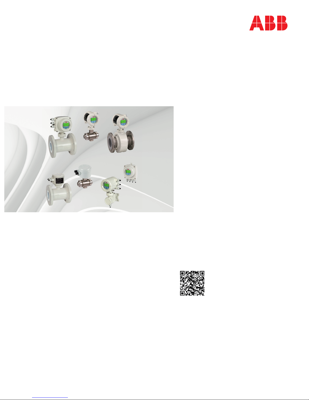
Additional Information
Additional documentation on ProcessMaster FEP630,
HygienicMaster FEH630 is available for download
free of charge at www.abb.com/flow.
Alternatively simply scan this code:
Page 2

2 ProcessMaster FEP630, HygienicMaster FEH630 ELECTROMAGNETIC FLOWMETER | SI/FEP630/FEH630/FM/CSA-EN REV. A
Table of contents
Change from one to two columns
1 Safety .......................................................................... 3
General information and instructions .................................. 3
Warnings .................................................................................... 3
Improper use ............................................................................. 4
Notes on data safety ............................................................... 4
Warranty provisions ................................................................. 4
2 Device designs ........................................................... 5
Version in integral mount design .......................................... 6
DIV. 1 ...................................................................................... 6
DIV. 2 ...................................................................................... 7
Version with remote mount design ...................................... 8
DIV. 1 ...................................................................................... 8
Div. 2 ....................................................................................... 9
Overview: The fast track to explosion protection device
data ........................................................................................... 11
3 Name plate ................................................................ 11
Device identification – name plate ...................................... 11
4 Housing ..................................................................... 12
Opening and closing the housing ....................................... 12
Dual- compartment housing ........................................... 12
Single-compartment housing ......................................... 13
Rotating the transmitter housing and LCD display .... 13
Installation instructions ........................................................ 14
cFMus .................................................................................. 14
Use in areas exposed to combustible dust .................. 14
Electrical connections ........................................................... 15
Process sealing ....................................................................... 15
High temperature design ..................................................... 16
5 Installing the plug-in cards..................................... 17
6 Operation in Div. 1 ................................................... 18
Electrical connections ........................................................... 18
Electric data for operation in Div. 1 ..................................... 19
Devices with HART protocol ............................................ 19
Special connection conditions ........................................ 21
Protection against electrostatic discharges ................ 21
Repair ................................................................................... 21
Temperature data .................................................................. 22
Surface temperature......................................................... 22
Measuring medium temperature as a function of liner
and flange material ........................................................... 22
Measuring medium temperature (Ex Data) for
ProcessMaster Model FEP631 ......................................... 23
Measuring medium temperature (Ex Data) for
ProcessMaster Model FEP632 ......................................... 24
Measuring medium temperature (Ex Data) for
HygienicMaster Model FEH631 ....................................... 25
7 Operation in Div. 2 ................................................... 27
Electrical connections ........................................................... 27
Electric data for operation in Div. 2 .................................... 29
Devices with HART protocol ............................................ 29
Special connection conditions ........................................ 30
Protection against electrostatic discharges................ 30
Temperature data .................................................................. 30
Surface temperature ........................................................ 30
Measuring medium temperature as a function of liner
and flange material ........................................................... 31
Measuring medium temperature (Ex Data) for
ProcessMaster Model FEP631 ......................................... 32
Measuring medium temperature (Ex Data) for
ProcessMaster Model FEP632 ......................................... 34
Measuring medium temperature (Ex Data) for
HygienicMaster Model FEH631 ....................................... 35
Measuring medium temperature (Ex Data) for
HygienicMaster Model FEH632 ....................................... 37
8 Commissioning ........................................................ 38
Checks before commissioning ............................................ 38
Output configuration for NAMUR switching amplifier ... 38
Configuring the current output ...................................... 38
Configuring the digital outputs ..................................... 38
9 Changing the type of protection ........................... 40
10 Maintenance ............................................................ 41
Sensor ...................................................................................... 41
Cleaning ................................................................................... 41
11 Repair ........................................................................ 41
Safety instructions ................................................................ 41
Spare parts .............................................................................. 42
Replacing the fuse ................................................................. 42
Replacing the frontend board ............................................. 43
Integral mount design ...................................................... 43
Remote mount design ...................................................... 45
Replacing the sensor ............................................................. 46
Returning devices .................................................................. 46
12 Recycling and disposal ........................................... 47
Dismounting ........................................................................... 47
Disposal ................................................................................... 47
13 Additional documents ............................................ 47
14 Appendix .................................................................. 48
Return form ............................................................................. 48
Installation diagram 3KXF000061G0009 .......................... 49
Page 3

ProcessMaster FEP630, HygienicMaster FEH630 ELECTROMAGNETIC FLOWMETER | SI/FEP630/FEH630/FM/CSA-EN REV. A 3
1 Safety
General information and instructions
These instructions are an important part of the product and
must be retained for future reference.
Installation, commissioning, and maintenance of the product
may only be performed by trained specialist personnel who have
been authorized by the plant operator accordingly. The specialist
personnel must have read and understood the manual and must
comply with its instructions.
For additional information or if specific problems occur that are
not discussed in these instructions, contact the manufacturer.
The content of these instructions is neither part of nor an
amendment to any previous or existing agreement, promise or
legal relationship.
Modifications and repairs to the product may only be performed
if expressly permitted by these instructions.
Information and symbols on the product must be observed.
These may not be removed and must be fully legible at all times.
The operating company must strictly observe the applicable
national regulations relating to the installation, function testing,
repair and maintenance of electrical products.
Warnings
The warnings in these instructions are structured as follows:
DANGER
The signal word ‘DANGER’ indicates an imminent danger.
Failure to observe this information will result in death or
severe injury.
WARNING
The signal word ‘WARNING’ indicates an imminent danger.
Failure to observe this information may result in death or
severe injury.
CAUTION
The signal word ‘CAUTION’ indicates an imminent danger.
Failure to observe this information may result in minor or
moderate injury.
NOTICE
The signal word
‘
NOTIC
E
’
indicates possible material damage.
Note
‘Note’ indicates useful or important information about the
product.
Page 4

4 ProcessMaster FEP630, HygienicMaster FEH630 ELECTROMAGNETIC FLOWMETER | SI/FEP630/FEH630/FM/CSA-EN REV. A
… 1 Safety
… Warnings
The device has been designed for use exclusively within the
technical limit values indicated on the identification plate and in
the data sheets.
When using measuring media, the following points must be
observed:
• Wetted parts such as measuring electrodes, liner,
grounding electrodes, grounding plates or protection
plates must not be damaged by the chemical and physical
properties of the measuring medium during the operating
time.
• Measuring media with unknown properties or abrasive
measuring media may only be used if the operator is able
to perform regular and suitable tests to ensure the safe
condition of the device
• The indications on the name plate must be observed
• Before use of corrosive or abrasive measuring media, the
operator must clarify the level of resistance of wetted
parts.
ABB will gladly support you in the selection, but cannot
accept any liability in doing so.
Improper use
The following are considered to be instances of improper use of
the device:
• Operation as a flexible compensating adapter in piping,
for example for compensating pipe offsets, pipe
vibrations, pipe expansions, etc.
• For use as a climbing aid, for example for mounting
purposes.
• For use as a bracket for external loads, for example as a
support for piping, etc.
• Material application, for example by painting over the
housing, name plate or welding/soldering on parts.
• Material removal, for example by spot drilling the housing.
Notes on data safety
This product is designed to be connected to and to
communicate information and data via a network interface.
It is operator’s sole responsibility to provide and continuously
ensure a secure connection between the product and your
network or any other network (as the case may be).
Operator shall establish and maintain any appropriate measures
(such as but not limited to the installation of firewalls,
application of authentication measures, encryption of data,
installation of anti-virus programs, etc.) to protect the product,
the network, its system and the interface against any kind of
security breaches, unauthorized access, interference, intrusion,
leakage and / or theft of data or information.
ABB Automation Products GmbH and its affiliates are not liable
for damages and / or losses related to such security breaches,
any unauthorized access, interference, intrusion, leakage and / or
theft of data or information.
Warranty provisions
Using the device in a manner that does not fall within the scope
of its intended use, disregarding this manual, using
underqualified personnel, or making unauthorized alterations
releases the manufacturer from liability for any resulting
damage. This renders the manufacturer's warranty null and void.
Change from two to one column
Page 5

ProcessMaster FEP630, HygienicMaster FEH630 ELECTROMAGNETIC FLOWMETER | SI/FEP630/FEH630/FM/CSA-EN REV. A 5
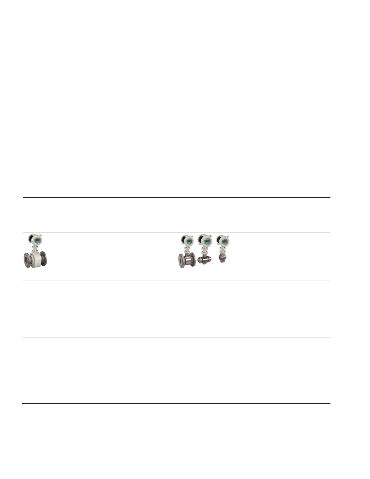
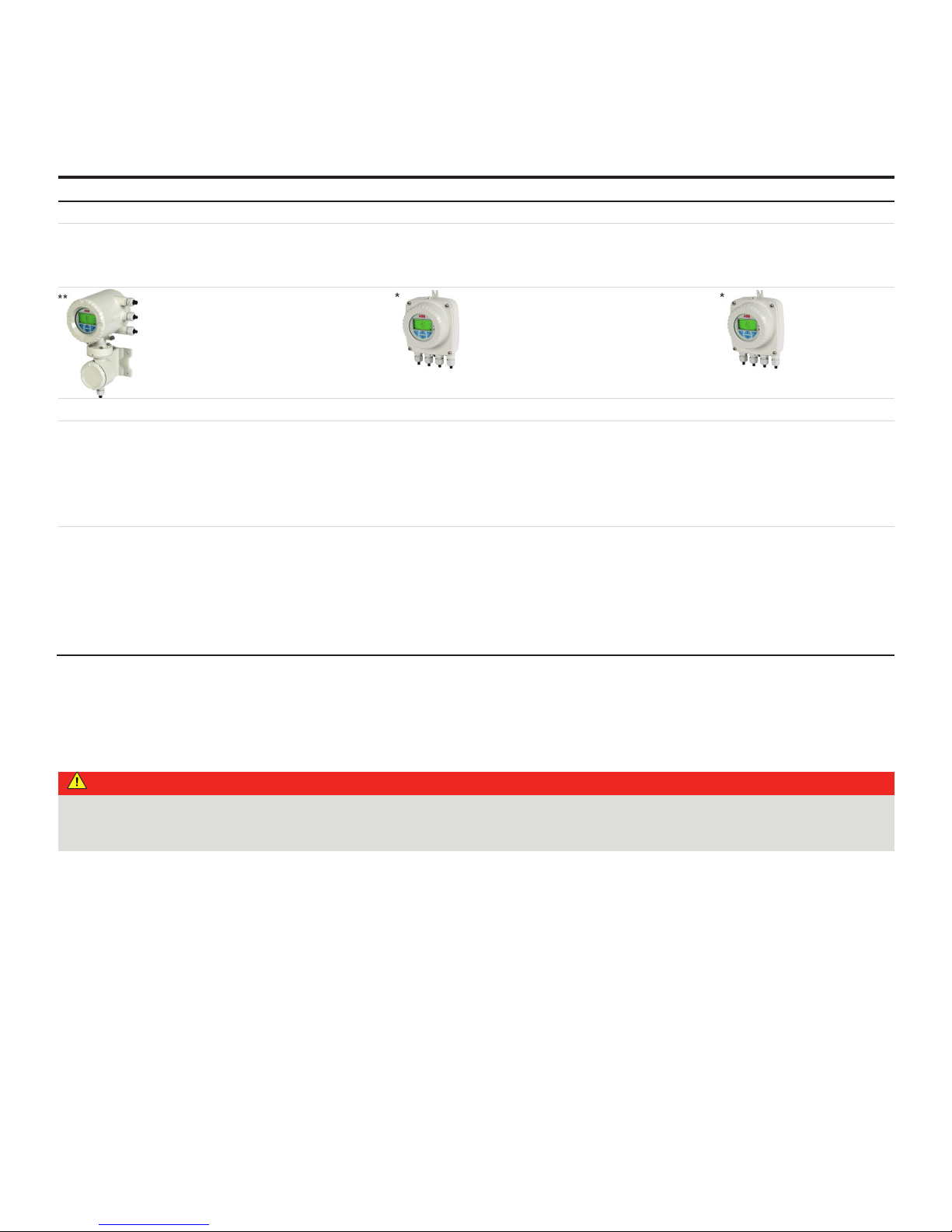
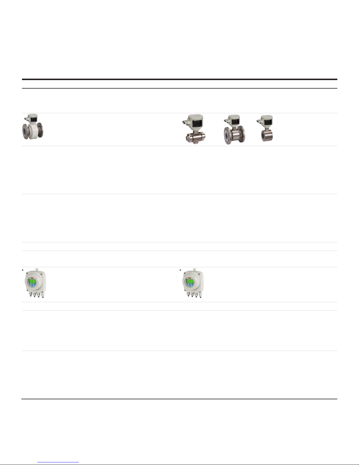
2 Device designs
Two device ranges are available in the 630 series. ProcessMaster 630 and HygienicMaster 630.
Two designs (integral mount / remote mount) are available within each device range.
This results in the following variants:
• ProcessMaster FEP631, integral mount device
• ProcessMaster FEP632, flow sensor remote mount design
• HygienicMaster FEH631, integral mount device
• HygienicMaster FEH632, flow sensor remote mount design
• Remote transmitter FET632 for ProcessMaster / HygienicMaster
Devices suitable for use in potentially explosive atmospheres feature the corresponding Ex mark on their name plates.
Moreover, each device design has a specific model number.
The parts of the model number relating to explosion protection are listed in the following table. The complete key to model numbers
is described in the device data sheet.
ProcessMaster FEP631, integral mount device
ProcessMaster FEP632, flow sensor remote mount design
HygienicMaster FEH631, integral mount device
HygienicMaster FEH632, flow sensor remote mount design
Remote transmitter for ProcessMaster / HygienicMaster
FEP631
FEP632
FEH631
FEH632
FET632
XX XX
Explosion protection
Without Y0
ATEX / IECEx (Zone 1 / 21) A1
ATEX / IECEx (Zone 2 / 22) A2
cFMus Class I, II, III Div. 1 (Zone 1 / 21)) F1
cFMus Class I, II, III Div. 2 (Zone 2 / 22) F2
NEPSI (Zone 1 / 21) S1
NEPSI (Zone 2 / 22) S2
Design / terminal box material / cable glands
Single-compartment / aluminum / M20 x 1.5 S1
Single-compartment / Aluminum / NPT ½ in S2
Dual-compartment / aluminum / M20 x 1.5 D1
Dual-compartment / Aluminum / NPT ½ in D2
Dual-compartment / stainless steel / M20 x 1.5 D3
Dual-compartment / stainless steel / NPT ½ in D4
Dual-compartment / aluminum / M20 x 1.5 (Ex ‘d’ cable gland) D6
Dual-compartment / stainless steel / M20 x 1.5 (Ex ‘d’ cable gland) D8
Remote mount / aluminum / M20 x 1.5 A1
Remote mount / Aluminum / NPT ½ in A2
Field mount housing / single-compartment / aluminum / M20 x 1.5 F1
Field mount housing / single-compartment / aluminum / NPT ½ in F2
Wall-mount housing / dual-compartment / aluminum / M20 x 1.5 W1
Wall-mount housing / dual-compartment / Aluminum / NPT ½ in W2
Wall-mount housing / dual-compartment / stainless steel / M20 x 1.5 W3
Wall-mount housing / dual-compartment / stainless steel / NPT ½ in W4
Wall-mount housing / dual-compartment / aluminum / M20 x 1.5 (Ex ‘d’ cable gland) W5
Wall-mount housing / dual-compartment / stainless steel / M20 x 1.5 (Ex ‘d’ cable gland) W7
Table 1: Excerpt from ordering information
Page 6
6 ProcessMaster FEP630, HygienicMaster FEH630 ELECTROMAGNETIC FLOWMETER | SI/FEP630/FEH630/FM/CSA-EN REV. A
… 2 Device designs
Version in integral mount design
The transmitter and the flowmeter sensor form a single mechanical entity.
The transmitter is available in two housing designs
• Single-compartment housing
This is suited for use in CI I Div. 2
In the single-compartment housing, the electronics chamber and the connection chamber in the transmitter are not separated
from each other.
• Dual- compartment housing:
This is suited for use in CI I Div. 1
In the dual-compartment housing, the electronics chamber and the connection chamber in the transmitter are separated from
each other.
Note
Further information on the Ex Approval of devices can be found in the type examination certificates or the relevant certificates at
www.abb.com/flow.
DIV. 1
Sensor
ProcessMaster 630 HygienicMaster 630
FEP631-F1 FEH631-F1
Div. 1 Div. 1
USA, FM approval USA, FM approval
Certificate: FM17US0062X Certificate: FM17US0062X
DN3-300:
S-XP-IS: CL I, Div 1, GPS ABCD T6...T1
DIP: CL II,III, Div 1, GPS EFG T6...T3B
>DN300:
CL I, ZN 1, AEx db eb mb [ia Ga] IIC T6…T1 Gb
DN3-100:
S-XP-IS: CL I, Div 1, GPS ABCD T6...T1
DIP: CL II,III, Div 1, GPS EFG T6...T3B
ZN 21, AEx tb [ia Da] IIIC T80°C...T165°C Db
Canada, FM approval Canada, cFM approval
Certificate: FM17CA0033X Certificate: FM17CA0033X
DN3-300:
S-XP-IS: CL I, Div 1, GPS BCD T6...T1
DIP: CL II,III, Div 1, GPS EFG T6...T3B
>DN300:
CL I, ZN 1, Ex db eb mb [ia Ga] IIC T6…T1 Gb
DN3-100:
S-XP-IS: CL I, Div 1, GPS BCD T6...T1
DIP: CL II,III, Div 1, GPS EFG T6...T3B
Ex tb [ia Da] IIIC T80°C...T165°C Db
Page 7
ProcessMaster FEP630, HygienicMaster FEH630 ELECTROMAGNETIC FLOWMETER | SI/FEP630/FEH630/FM/CSA-EN REV. A 7
DIV. 2
Sensor
ProcessMaster 630 HygienicMaster 630
FEP631-F2 FEH631-F2
Div. 2 Div. 2
USA, FM approval USA, FM approval
Certificate: FM17US0062X Certificate: FM17US0062X
NI: CL I, Div 2, GPS ABCD T6...T1 NI: CL I, Div 2, GPS ABCD T6...T1
DIP: CL II,III, Div 2, GPS EFG T6…T3B
CL I, ZN 2, AEx ec IIC T6…T1
ZN 21, AEx tb IIIC T80°C...T165°C
DIP: CL II,III, Div 2, GPS EFG T6…T3B
CL I, ZN 2, AEx ec IIC T6…T1
ZN 21, AEx tb IIIC T80°C...T165°C
Canada, cFM approval Canada, cFM approval
Certificate: FM17CA0033X Certificate: FM17CA0033X
NI: CL I, Div 2, GPS ABCD T6...T1 NI: CL I, Div 2, GPS ABCD T6...T1
DIP: CL II,III, Div 2, GPS EFG T6…T3B
CL I, ZN 2, Ex ec IIC T6...T1 Gc
Ex tb IIIC T80°C...T165°C Db
DIP: CL II,III, Div 2, GPS EFG T6…T3B
CL I, ZN 2, Ex ec IIC T6...T1 Gc
Ex tb IIIC T80°C...T165°C Db
* Single-compartment housing
** Dual-compartment housing
Page 8
8 ProcessMaster FEP630, HygienicMaster FEH630 ELECTROMAGNETIC FLOWMETER | SI/FEP630/FEH630/FM/CSA-EN REV. A
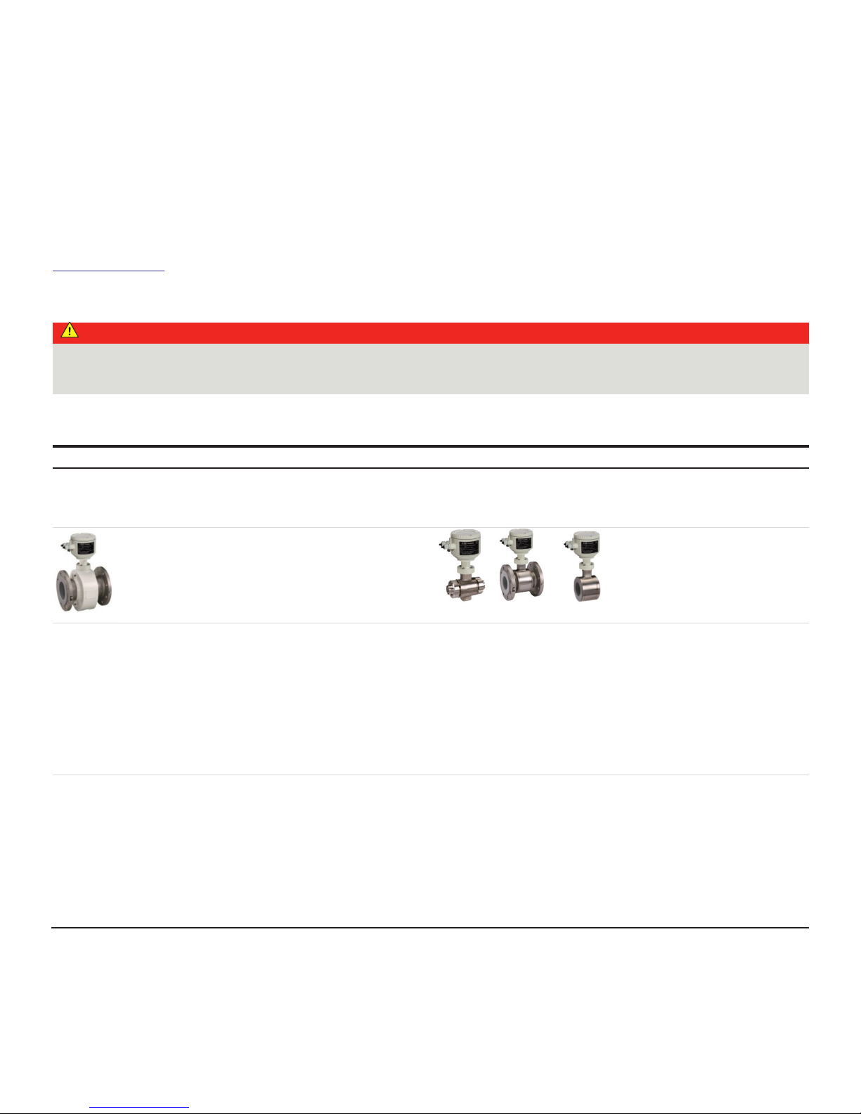
… 2 Device designs
Version with remote mount design
The transmitter is mounted in a separate location from the flowmeter sensor. The electrical connection between the transmitter and
flowmeter sensor may only be established using the signal cable supplied.
A maximum signal cable length of 200 m (656 ft) is possible.
Note
Further information on the Ex Approval of devices can be found in the type examination certificates or the relevant certificates at
www.abb.com/flow.
DIV. 1
DANGER
Explosion hazard caused by incorrect transmitter installation
The FET632-Y0 transmitter does not have Ex Approval.
The FET632-Y0 transmitter may not be installed and operated in potentially explosive atmospheres.
The following table presents the combination of the FEP632, FEH632 sensor in explosion-proof design with the FET632 transmitter.
Sensor
ProcessMaster 630 HygienicMaster 630
FEP632-F1 FEH632-F1
in Ex area, Div. 1 in Ex area, Div. 1
USA, FM approval USA, FM approval
Certificate: FM17US0062X Certificate: FM17US0062X
DN3-300:
S-XP-IS: CL I, Div 1, GPS BCD T6...T1
DIP: CL II,III, Div 1, GPS EFG T6...T3B
DN3-100:
S-XP-IS: CL I, Div 1, GPS BCD T6...T1
DIP: CL II,III, Div 1, GPS EFG T6...T3B
>DN300:
CL I, ZN 1, AEx db eb mb [ia Ga] IIB+H2 T6…T1 Gb
ZN 21, AEx tb [ia Da] IIIC T80°C...T165°C Db
Canada, cFM approval Canada, cFM approval
Certificate: FM17CA0033X Certificate: FM17CA0033X
DN3-300:
S-XP: CL I, Div 1, GPS BCD T6...T1
DIP: CL II,III, Div 1, GPS EFG T6…T3B
DN3-100:
S-XP: CL I, Div 1, GPS BCD T6...T1
DIP: CL II,III, Div 1, GPS EFG T6…T3B
>DN300:
CL I, ZN 1, Ex db eb mb IIB+H2 T6…T1 Gb
Ex tb IIIC T80°C...T165°C Db
Page 9
ProcessMaster FEP630, HygienicMaster FEH630 ELECTROMAGNETIC FLOWMETER | SI/FEP630/FEH630/FM/CSA-EN REV. A 9
Sensor
Transmitter
FET632-F1 FET632-F2 FET632-Y0
in Ex area, Div. 1 in Ex area, Div. 2 outside the potentially explosive
atmosphere
USA, FM approval USA, FM approval -
Certificate: FM17US0062X Certificate: FM17US0062X No Ex Approval!
XP-IS: CL I, Div 1, GPS BCD T6 NI: CL I, Div 2, GPS ABCD T6
DIP: CL II,III, Div 1, GPS EFG T6
CL I, ZN 1, AEx db [ia Ga] IIB+H2 T6 Gb
ZN 21, AEx tb [ia Da] IIIC T80°C Db
DIP: CL II,III, Div 2, GPS EFG T6
CL I, ZN 2, AEx ec IIC T6
ZN 21, AEx tb IIIC T80°C
Canada, cFM approval Canada, cFM approval
Certificate: FM17CA0033X Certificate: FM17CA0033X
XP-IS: CL I, Div 1, GPS BCD T6 NI: CL I, Div 2, GPS ABCD T6
DIP: CL II,III, Div 1, GPS EFG T6
CL I, ZN 1, Ex db [ia Ga] IIB+H2 T6 Gb
Ex tb [ia Da] IIIC T80°C Db
DIP: CL II,III, Div 2, GPS EFG T6
Ex ec IIC T6 Gc
Ex tb IIIC T80°C Db
* Single-compartment housing
** Dual-compartment housing
Div. 2
DANGER
Explosion hazard caused by incorrect transmitter installation
The FET632-Y0 transmitter does not have Ex Approval.
The FET632-Y0 transmitter may not be installed and operated in potentially explosive atmospheres.
Page 10
10 ProcessMaster FEP630, HygienicMaster FEH630 ELECTROMAGNETIC FLOWMETER | SI/FEP630/FEH630/FM/CSA-EN REV. A
… 2 Device designs
… Version with remote mount design
The following table presents the combination of the FEP632, FEH632 sensor in explosion-proof design with the FET632 transmitter.
Sensor
ProcessMaster 630 HygienicMaster 630
FEP632-F2 FEH632-F2
in Ex area, Div. 2 in Ex area, Div. 2
USA, FM approval USA, FM approval
Certificate: FM17US0062X Certificate: FM17US0062X
NI: CL I, Div 2, GPS ABCD T6...T1 NI: CL I, Div 2, GPS ABCD T6...T1
DIP: CL II,III, Div 2, GPS EFG T6…T6…T3B
CL I, ZN 2, AEx ec IIC T6…T1
ZN 21, AEx tb IIIC T80°C...T165°C
DIP: CL II,III, Div 2, GPS EFG T6…T6…T3B
CL I, ZN 2, AEx ec IIC T6…T1
ZN 21, AEx tb IIIC T80°C...T165°C
Canada, cFM approval Canada, cFM approval
Certificate: FM17CA0033X Certificate: FM17CA0033X
NI: CL I, Div 2, GPS ABCD T6...T1 NI: CL I, Div 2, GPS ABCD T6...T1
DIP: CL II,III, Div 2, GPS EFG T6…T3B
CL I, ZN 2, Ex ec IIC T6...T1 Gc
Ex tb IIIC T80°C...T165°C Db
DIP: CL II,III, Div 2, GPS EFG T6…T3B
CL I, ZN 2, Ex ec IIC T6...T1 Gc
Ex tb IIIC T80°C...T165°C Db
Transmitter
FET632-F2 FET632-Y0
In Ex area, Zone 2, 22 outside the potentially explosive atmosphere
USA, FM approval -
Certificate: FM17US0062X No Ex Approval!
NI: CL I, Div 2, GPS ABCD T6
DIP: CL II,III, Div 2, GPS EFG T6
CL I, ZN 2, AEx ec IIC T6
ZN 21, AEx tb IIIC T80°C
Canada, cFM approval
Certificate: FM17CA0033X
NI: CL I, Div 2, GPS ABCD T6
DIP: CL II,III, Div 2, GPS EFG T6
Ex ec IIC T6 Gc
Ex tb IIIC T80°C Db
* Single-compartment housing
** Dual-compartment housing
Change from one to two columns
Page 11
ProcessMaster FEP630, HygienicMaster FEH630 ELECTROMAGNETIC FLOWMETER | SI/FEP630/FEH630/FM/CSA-EN REV. A 11
Overview: The fast track to explosion
protection device data
These safety instructions related to explosion protection are
valid in conjunction with the following test documentation and
certificates:
Table 2: Validity range
Model Operation in
zone
Electrical connection and
explosion protection
data
Chapter
ProcessMaster 630
FEP631-F1 Div. 1 Operation in Div. 1
FEP631-F2 Div. 2 Operation in Div. 2
FEP632-F1 and FET632-F1 Div. 1 Operation in Div. 1
FEP632-F1 and FET632-Y0 Div. 1 Operation in Div. 1
FEP632-F2 and FET632-F2 Div. 2 Operation in Div. 2
FEP632-F2 and FET632-Y0 Div. 2 Operation in Div. 2
HygienicMaster 630
FEH631-F1 Div. 1 Operation in Div. 1
FEH631-F2 Div. 2 Operation in Div. 2
FEH632-F1 and FET632-F1 Div. 1 Operation in Div. 1
FEH632-F1 and FET632-Y0 Div. 1 Operation in Div. 1
FEH632-F2 and FET632-F2 Div. 2 Operation in Div. 2
FEH632-F2 and FET632-Y0 Div. 2 Operation in Div. 2
Table 3: Overview
Note
All documentation, declarations of conformity, and certificates
are available in ABB's download area.
www.abb.com/flow
3 Name plate
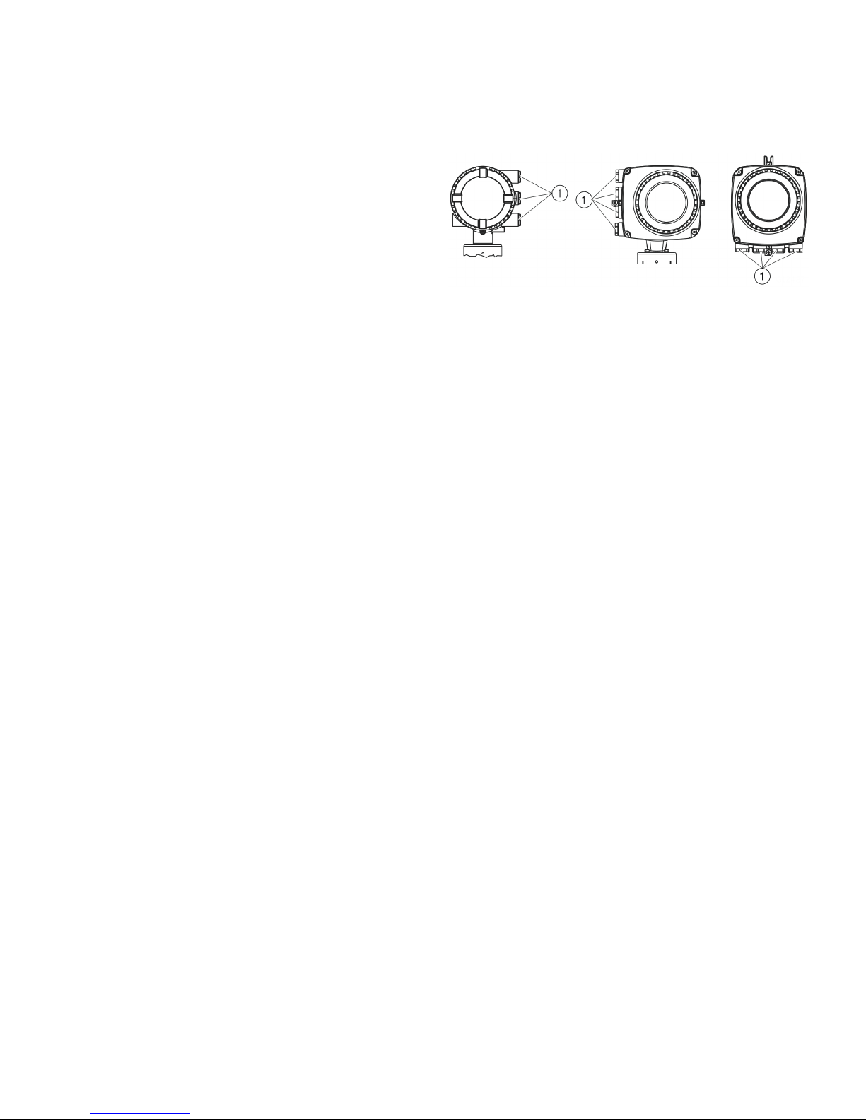
Device identification – name plate
Note
The name plate shown is an example.
The name plate attached to the device can differ from this
representation.
1Model number (for more detailed
information about the technical
design, refer to the data sheet or
the order confirmation)
2 Order number / Serial number
for identification by the
manufacturer
3Meter size and nominal pressure
rating
4 Material: Flange / liner /
electrode
5 T
med
= maximum permissible
measuring medium temperature
T
amb
= maximum permissible
ambient temperature
6 Calibration value Q
max.
DN
7Calibration value Ss (span)
Calibration value Sz (zero point)
8 Excitation frequency of the
sensor
9Software version
j Year of manufacture
k CE mark
l IP rating in accordance with
EN 60529
m Supplementary information: EE =
grounding electrodes,
TFE = partial filling electrode
n Marking indicating whether the
pressure equipment is in the
scope of the Pressure Equipment
Directive.
Information on the relevant fluid
group.
Fluid group 1 = hazardous fluids,
liquid, gaseous. (Pressure
Equipment Directive = PED).
If the pressure equipment is not in
the scope of the Pressure
Equipment Directive 2014/68/EC,
it is classified in accordance with
SEP (= sound engineering
practice) in accordance with Art. 3
para. 3 of the PED.
If no such information is present,
it means that the device does not
claim to be in accordance with the
requirements of the Pressure
Equipment Directive 2014/68/EC.
Water supplies and connected
equipment accessories are
classed as an exception in
accordance with guideline 1/16 of
Art. 1 Para. 3.2 of the Pressure
Equipment Directive.
o Ex marking in accordance with
ATEX (example)
p Ex marking in accordance with
IECEx (example)
Figure 1: Name plate (example)
Note
Devices with 3A approval, EHEDG certificate, SIL are identified
with an additional plate.
Scope Certificate
ATEX Zone 1 / 21 FM17ATEX0016X
ATEX Zone 2 / 22 FM17ATEX 0017X
IEC Ex Zone 1 / 21 IECEx FME 17.0001X
IEC Ex Zone 2 / 22 IECEx FME 17.0001X
FMus Div 1 (USA) FM17US0062X
FMus Div 2 (USA) FM17US0062X
cFM Div 1 (Canada) FM17CA0033X
cFM Div 2 (Canada) FM17CA0033X
Page 12
12 ProcessMaster FEP630, HygienicMaster FEH630 ELECTROMAGNETIC FLOWMETER | SI/FEP630/FEH630/FM/CSA-EN REV. A
4 Housing
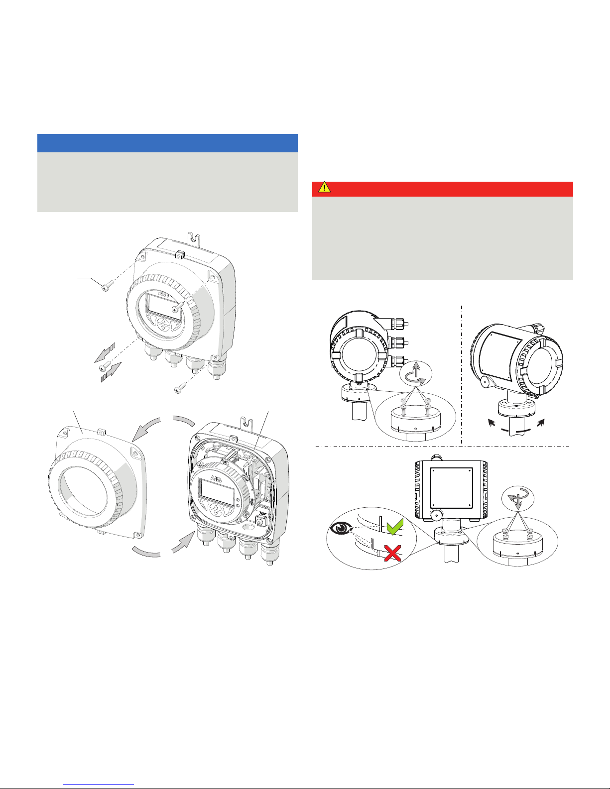
Opening and closing the housing
DANGER
Danger of explosion if the device is operated with the
transmitter housing or terminal box open!
Before opening the transmitter housing or the terminal box,
note the following points:
• A valid fire permit must be present.
• Make sure that there is no explosion hazard.
• Switch off the power supply and wait for t > 20 minutes
before opening.
WARNING
Risk of injury due to live parts!
When the housing is open, explosion protection and contact
protection is not provided and EMC protection is limited.
• Before opening the housing, switch off the power supply.
Dual- compartment housing
NOTICE
Potential adverse effect on the IP rating
• Check the O-ring gasket for damage and replace it if
necessary before closing the housing cover.
• Check that the O-ring gasket is properly seated when
closing the housing cover.
G11738-01
AB
C
1 1
2
1
2
2
A Integral mount design
B Remote mount design
C Transmitter, terminal space,
signal cable
Figure 2: Cover lock (example)
Open the housing:
1. Release the cover lock by screwing in the Allen screw
2.
2. Unscrew cover
1.
Close the housing:
1. Screw on the cover
1.
2. After closing the housing, lock the cover by unscrewing
the Allen screw
2.
Page 13
ProcessMaster FEP630, HygienicMaster FEH630 ELECTROMAGNETIC FLOWMETER | SI/FEP630/FEH630/FM/CSA-EN REV. A 13
Single-compartment housing
NOTICE
Potential adverse effect on the IP rating
• Check the gasket for damage and replace it if necessary
before closing the housing cover.
• Check that the gaskets are properly seated when closing
the housing cover.
G12149
C
AA
B
D
1
2 3
1 Cover screws
2 Transmitter housing cover
3 Gasket
Figure 3: Open / close single-compartment housing
Open transmitter housing: Perform steps
A and B.
Close transmitter housing: Perform steps
C and D.
Rotating the transmitter housing and LCD display
Depending on the installation position, the transmitter housing
or LCD display can be rotated to enable horizontal readings.
Transmitter housing
DANGER
Damaging the device carries a risk of explosion!
When the screws for the transmitter housing are loosened, the
explosion protection is suspended.
Tighten all screws prior to commissioning.
Never disconnect the transmitter housing from the sensor.
Only loosen the screws shown when rotating the transmitter
housing!
Rotate transmitter housing: Perform steps
A to C.
G11569
AB
90°
90°
C
Figure 4: Rotate transmitter housing
Page 14
14 ProcessMaster FEP630, HygienicMaster FEH630 ELECTROMAGNETIC FLOWMETER | SI/FEP630/FEH630/FM/CSA-EN REV. A
… 4 Housing
Installation instructions
cFMus
The installation, commissioning, maintenance and repair of
devices in areas with explosion hazard must only be carried out
by appropriately trained personnel.
The operator must strictly observe the applicable national
regulations with regard to installation, function tests, repairs,
and maintenance of electrical devices. (for example, NEC, CEC).
Use in areas exposed to combustible dust
When using the device in areas exposed to combustible dusts
(dust ignition), the following points must be observed:
• The maximum surface temperature of the device may not
up-scale the following values.
FEP631, FEH631 80 °C (176 °F)
FEP632, FEH632 80 °C (176 °F)
FET632 80 °C (176 °F)
• The process temperature of the attached piping may upscale 80 °C (176 °F).
• Approved dust-proof cable glands must be used when
operating in Zone 21, 22 or in Class II, Class III.
• In potentially explosive atmospheres, the signal cable
must measure at least 5 m (16.40 ft).
Cable entry
1 Transport protection plugs
Figure 5: Cable entry
The devices are delivered with ½ in NPT or PF ½ in threads with
transport protection plugs.
Unused cable entries must be sealed off prior to commissioning
using either approved pipe fittings or cable glands in accordance
with national regulations (NEC, CEC).
Make sure that the pipe fittings, cable glands and, if applicable,
sealing plugs are installed properly and tight.
If the device is to be operated in areas with combustible dusts, a
threaded pipe connection or cable gland with suitable approval
must be used.
The use of standard cable glands and seals is prohibited.
Any unused cable entries must be sealed before commissioning
in accordance with the applicable standards.
Note
Devices which are certified for use in North America are supplied
with a ½ in. NPT thread only and without cable glands.
Page 15

ProcessMaster FEP630, HygienicMaster FEH630 ELECTROMAGNETIC FLOWMETER | SI/FEP630/FEH630/FM/CSA-EN REV. A 15
Electrical connections
Temperature resistance for the connecting cable
The temperature at the cable entries of the device is dependent
on the measuring medium temperature T
medium
and the ambient
temperature T
amb
.
For the electrical connection of the device, use only cables with
sufficient temperature resistance in accordance with the
following table.
Device in integral mount design
T
amb
Temperature resistance
á 50 °C (á 122 °F) â 60 °C (â 140 °F)
á 60 °C (á 140 °F) â 70 °C (â 158 °F)
Model in remote mount design
T
amb
Temperature resistance
á 50 °C (á 122 °F) â 70 °C (â 158 °F)
á 60 °C (á 140 °F) â 80 °C (â 176 °F)
Grounding
The sensor must be grounded in accordance with the applicable
international standards.
Perform grounding of the device in accordance with Electrical
connections on page 18.
In accordance with NEC standards, an internal ground
connection is present in the device between the sensor and the
transmitter.
Perform grounding of the device in accordance with Electrical
connections on page 18.
Process sealing
In accordance with the ‘North American Requirements for
Process Sealing between Electrical Systems and Flammable or
Combustible Process Fluids’.
Note
The device is suitable for use in Canada.
A maximum surface temperature of 165 °C (329 °F) must not be
up-scaled when used in Class II, Groups E, F and G.
All cable conduits should be sealed from the device within a
distance of 18 in (457 mm).
Among other things, devices with cable conduits are connected
to the electrical installation which makes it possible for
measuring media to reach the electric system.
To prevent process media from seeping into the electrical
installation, the instruments are equipped with process seals
which meet the requirements of ANSI / ISA 12.27.01.
The flow measurement devices are designed as ‘single seal
devices’ and are suited for the measurement of non-flammable
fluids.
In accordance with the requirements of standard ANSI/ISA
12.27.01, the existing operating limits of temperature, pressure
and pressure bearing parts must be reduced to the following
limit values:
Page 16
16 ProcessMaster FEP630, HygienicMaster FEH630 ELECTROMAGNETIC FLOWMETER | SI/FEP630/FEH630/FM/CSA-EN REV. A
… 4 Housing
… Process sealing
Max. permissible operating temperature in acc. with ISA12.27.01
Liner material Nominal diameter Max. operating temperature in
acc. with ISA12.27.01
Hard rubber DN15 to 400 0 °C to 90 °C (32 °F to 194 °F)
DN450 to 2000 Max. 90 °C (194 °F)
Soft rubber DN50 to 400 0 °C to 60 °C (32 °F to 140 °F)
DN450 to 2000 0 °C to 60°C (140 °F)
PTFE DN10 to 400 Æ40 °C to 170 °C (Æ40 °F to 338 °F)
DN450 to 1000 Max. 130 °C (266 °F)
Thick PTFE DN10 to 400 Æ40 °C to 170 °C (Æ40 °F to 338 °F)
PFA DN3 to 200 Æ40 °C to 170 °C (Æ40 °F to 338 °F)
ETFE DN25 to 400 Æ40 °C to 150 °C (Æ40 °F to 302 °F)
DN450 to 1000 Max. 130 °C (266 °F)
Ceramic carbide DN25 to 400 0 °C to 80 °C (32 °F to 176 °F)
DN450 to 1000 0 °C to 80 °C (32 °F to 176 °F)
Max. permissible nominal pressure rating in acc. with
ISA12.27.01
Model Nominal diameter Max. nominal
pressure
Lining material
FEH DN10 to DN40 Class 150 All
DN50 to DN100 Class 150 All
FEP DN10 to DN50 Class 150 All
DN65 to DN400 Class 300 All
DN65 to DN400 Class 600 Hard rubber
DN450 to DN2600 Class 300 All
The operating temperature of the devices is determined by the
fluid temperature and the ambient temperature.
High temperature design
The high temperature design allows for complete thermal
insulation of the sensor, up to the maximum illustrated device
height.
The pipeline and sensor must be insulated after installing the
unit according to the following illustration.
The thermal resistance of the insulation may not up-scale
θ = 0.036 W/(mK); if it does, the thickness of the insulation must
be reduced accordingly.
1 Insulation
Figure 6: Insulation
Change from two to one column
Page 17
ProcessMaster FEP630, HygienicMaster FEH630 ELECTROMAGNETIC FLOWMETER | SI/FEP630/FEH630/FM/CSA-EN REV. A 17
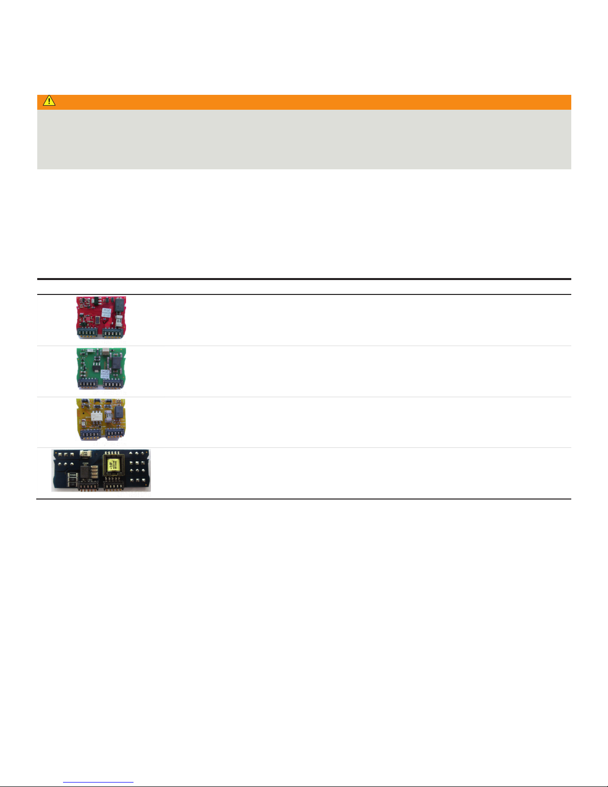
5 Installing the plug-in cards
WARNING
Loss of Ex Approval!
Loss of Ex Approval due to retrofitting of plug-in cards on devices for use in potentially explosive atmospheres.
• Devices for use in potentially explosive atmospheres may not be retrofitted with plug-in cards.
• If devices are to be used in potentially explosive atmospheres, the required plug-in cards must be specified when the order is
placed.
Note
The AS plug-in card (24 V DC loop power supply) may only be used to power the internal inputs and outputs on the device.
It must not be used to power external circuits!
Optional plug-in cards
The transmitter has two slots (OC1, OC2) into which plug-in cards can be inserted to extend inputs and outputs. The slots are located
on the transmitter motherboard and can be accessed after removing the front housing cover.
Plug-in card Description Number
*
Current output, 4 to 20 mA passive (red)
Order no.: 3KQZ400029U0100
Maximum of two plug-in cards
Passive digital output (green)
Order no.: 3KQZ400030U0100
Maximum of one plug-in card
Passive digital input (yellow)
Order no.: 3KQZ400032U0100
Maximum of one plug-in card
Loop power supply 24 V DC (blue)
Order no.: 3KQZ400031U0100
Maximum of one plug-in card
* The ‘Number’ column indicates the maximum number of plug-in cards of the same type that can be used.
Page 18
18 ProcessMaster FEP630, HygienicMaster FEH630 ELECTROMAGNETIC FLOWMETER | SI/FEP630/FEH630/FM/CSA-EN REV. A
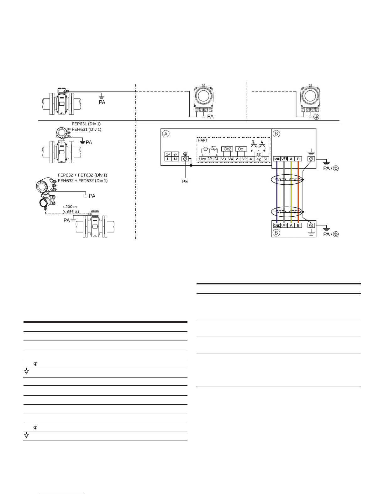
6 Operation in Div. 1
Electrical connections
FEP632 sensor (Div 1) FET632 transmitter (Div 2) FET632 transmitter outside the hazardous area
A Transmitter
B Sensor
Figure 7: Electrical connections
Change from one to two columns
Note
For detailed information on grounding the transmitter and the
sensor, please refer to the operating or commissioning
instruction!
Connections for the power supply
AC power supply
Terminal Function / comments
L Phase
N Neutral conductor
PE / Protective earth (PE)
/ PA Potential equalization
DC voltage supply
Terminal Function / comments
1+ +
2Æ Æ
PE / Protective earth (PE)
/ PA Potential equalization
Connections for inputs and outputs
Terminal Function / comments
Uco / 32
31 / 32
Current output 4 to 20 mA- / HART output, active
or
Current output 4 to 20 mA- / HART output, passive
41 / 42 Passive digital output DO1
51 / 52 Passive digital output DO2
V1 / V2
V3 / V4
Plug-in card, slot OC1
Plug-in card, slot OC2
Plug-in cards may not be retrofitted in devices with explosion
protection on-site – loss of Ex Approval.
Page 19

ProcessMaster FEP630, HygienicMaster FEH630 ELECTROMAGNETIC FLOWMETER | SI/FEP630/FEH630/FM/CSA-EN REV. A 19
Connecting the signal cable
Only for remote mount design.
The sensor housing and transmitter housing must be connected
to potential equalization.
Terminal Function / comments
UFE Sensor power supply
GND Ground
A Data line
B Data line
Functional earth / Shielding
Change from two to one column
Electric data for operation in Div. 1
Devices with HART protocol
When operating in potentially explosive areas, observe the following electrical data for the signal inputs and outputs of the
transmitter.
Current output terminals 31 / 32 / Uco can be operated on-site in active or passive mode through appropriate switching.
Model: FEP631, FEH631 or FET632 Type of protection
Outputs on basic device ‘e’ / ‘XP’ ‘ia’ / ‘IS’
U
M
[V]
I
M
[A]
U
O
U
I
[V]
I
O
[mA]
I
I
[mA]
P
O
[mW]
P
I
[mW]
C
O
[nF]
C
I
[nF]
C
OPA
[nF]
C
IPA
[nF]
L
O
[mH] L
I
[mH]
Current / HART output 31 / UCO, active
Terminals 31 / U
CO
30 0.2 30 30 115 115 815 815 10 10 5 5 0.08 0.08
Current / HART output 31 / 32, passive
Terminals 31 / 32
30 0.2 — 30 — 115
—
815 — 27 — 5 0.08 0.08
Digital output 41 / 42, active*
Terminals 41 / 42 and V1 / V2*
30 0.1 27.8 30 119 30 826 225 20 20 29 29 0.22 0.22
Digital output 41 / 42, passive
Terminals 41 / 42
30 0.1 — 30 — 30
—
225 — 27 — 5
—
0.08
Digital output 51 / 52, active*
Terminals 51 / 52 and V1 / V2*
30 0.1 27.8 30 119 30 826 225 20 20 29 29 0.22 0.22
Digital output 51 / 52, passive
Terminals 51 / 52
30 0.1 — 30 — 30
—
225 — 27 — 5
—
0.08
All outputs are electrically isolated from each other and from the power supply.
Digital outputs 41 / 42 and 51 / 52 are not electrically isolated from each other. Terminals 42 / 52 have the same potential.
Page 20

20 ProcessMaster FEP630, HygienicMaster FEH630 ELECTROMAGNETIC FLOWMETER | SI/FEP630/FEH630/FM/CSA-EN REV. A
… 6 Operation in Div. 1
… Electric data for operation in Div. 1
Model: FEP631, FEH631 or FET632 Type of protection
Inputs and outputs with optional plug-in
cards
‘e’ / ‘XP’ ‘ia’ / ‘IS’
U
M
[V]
I
M
[A]
U
O
U
I
[V]
I
O
[mA]
I
I
[mA]
P
O
[mW]
P
I
[mW]
C
O
[nF]
C
I
[nF]
C
OPA
[nF]
C
IP
A
[nF]
L
O
[mH] L
I
[mH]
Current output V3 / V4, active*
Terminals V3 / V4 and V1 / V2*
30 0.1 27.8 30 119 30 826 225 29 29 117 117 0.4 0.4
Current output V1 / V2, passive**
Current output V3 / V4, passive**
Terminals V1 / V2** or V3 / V4**
30 0.1 — 30 — 68 — 510
—
45 — 59 — 0.27
Digital output V3 / V4, active*
Terminals V3 / V4 and V1 / V2*
30 0.1 27.8 30 119 68 826 225 17 17 31 31 0.4 0.4
Digital output V1 / V2, passive**
Digital output V3 / V4, passive**
Terminals V1 / V2** or V3 / V4**
30 0.1 — 30 — 30 — 225
—
13 — 16 — 0.27
Digital input V3 / V4, active*
Terminals V3 / V4 and V1 / V2
30 0.1 27.8 30 119 3.45 826 25.8 17 17 31 31 0.4 0.4
Digital input V1 / V2, passive*
Digital input V3 / V4, passive*
Terminals V1 / V2** or V3 / V4**
30 0.1 — 30 — 3.45 — 25.8
—
13 — 16 — 0.27
* Only in conjunction with additional ‘24 V DC loop power supply (blue)’ plug-in card in slot OC1.
** The terminal assignment depends on the model number or the slot assignments. For connection examples, refer to Installation in the operating instruction.
Change from one to two columns
Page 21

ProcessMaster FEP630, HygienicMaster FEH630 ELECTROMAGNETIC FLOWMETER | SI/FEP630/FEH630/FM/CSA-EN REV. A 21
Special connection conditions
Note
The AS plug-in card (24 V DC loop power supply) may only be
used to power the internal inputs and outputs on the device.
It must not be used to power external circuits!
Note
If the protective earth (PE) is connected in the flowmeter's
terminal box, you must ensure that no dangerous potential
difference can arise between the protective earth (PE) and the
potential equalization (PA) in areas with explosion risk.
Note
For devices with a power supply of 16 to 30 V DC, on-site external
overvoltage protection must be provided.
It must be ensured that the overvoltage is limited to 140 % (=
42 V DC) of the maximum operating voltage.
The output circuits are designed so that they can be connected
to both intrinsically-safe and non-intrinsically-safe circuits.
• Combining intrinsically safe and non-intrinsically safe circuits
is not permitted.
• On intrinsically safe circuits, potential equalization should be
established along the entire length of the cable used for the
signal outputs.
• The rated voltage of the non-intrinsically safe circuits is
U
M
= 30 V.
• Intrinsic safety is preserved If the rated voltage U
M
= 30 V is
not up-scaled when connections are established to nonintrinsically safe external circuits.
• The information in Changing the type of protection on
page 40 must be observed when changing the type of
protection.
The concept of intrinsic safety allows several approved
intrinsically safe devices to be interconnected without additional
intrinsic safety installation checks, if the relevant installation
standards are observed.
Devices connected to the relevant equipment must not be
operated at over 250 V
rms
AC or 250 V DC to ground.
Installation in the USA or Canada must comply with ANSI / ISA
RP 12.6, ‘Installation of intrinsically safe systems for hazardous
(classified) locations’, the ‘National Electrical Code (ANSI / NFPA
70), sections 504, 505’ and the ‘Canadian electrical code (C22.1-
02)’.
Protection against electrostatic discharges
DANGER
Risk of explosion!
The painted surface of the device can store electrostatic
charges.
As a result, the housing can form an ignition source due to
electrostatic discharges in the following conditions:
• The device is operated in environments with a relative
humidity of á 30 %.
• The painted surface of the device is thereby relatively free
from impurities such as dirt, dust or oil.
• Instructions on avoiding ignition in potentially explosive
environments due to electrostatic discharges in
accordance with EN TR50404 and IEC 60079-32-1 must be
observed!
Instructions on cleaning
The painted surface of the device may be cleaned only using a
moist cloth.
Repair
Devices of type of protection ‘d’ are equipped with flameproof
joints in the housing. Contact ABB before commencing repair
work.
Page 22

22 ProcessMaster FEP630, HygienicMaster FEH630 ELECTROMAGNETIC FLOWMETER | SI/FEP630/FEH630/FM/CSA-EN REV. A
… 6 Operation in Div. 1
Temperature data
Surface temperature
Model name Surface temperature
FEP632, FEH632 T 80 °C (176 °F)
FEP631 EH631 T 80 °C (176 °F)
FET632 T 80 °C (176 °F)
The surface temperature depends on the fluid temperature.
With increasing measuring medium temperature > 60 °C (140 °F)
or > 80 °C (176 °F), the surface temperature also increases to the
level of the measuring medium temperature.
Note
The maximum permissible measuring medium temperature
depends on the liner and flange material, and is limited by the
operating values in the following tables.
Change from two to one column
Measuring medium temperature as a function of liner and flange material
Model FEP631, FEP632 Measuring medium temperature range (operating data)
Lining material Flange material Minimum Maximum
Hard rubber Steel Æ10 °C (14 °F)
Æ5 °C (23 °F)*
85 °C (185 °F)
80 °C (176 °F)*
Hard rubber Stainless steel Æ15 °C (5 °F)
Æ5 °C (23 °F)*
85 °C (185 °F)
80 °C (176 °F)*
Soft rubber Steel Æ10 °C (14 °F) 60 °C (140 °F)
Soft rubber Stainless steel Æ15 °C (5 °F) 60 °C (140 °F)
PTFE Steel Æ10 °C (14 °F) 130 °C (266 °F)
PTFE Stainless steel Æ25 °C (Æ13 °F) 130 °C (266 °F)
PFA Steel Æ10 °C (14 °F) 180 °C (356 °F)
PFA Stainless steel Æ25 °C (Æ13 °F) 180 °C (356 °F)
Thick PTFE Steel Æ10 °C (14 °F) 180 °C (356 °F)
Thick PTFE Stainless steel Æ25 °C (-13 °F) 180 °C (356 °F)
ETFE Steel Æ10 °C (14 °F) 130 °C (266 °F)
ETFE Stainless steel Æ25 °C (Æ13 °F) 130 °C (266 °F)
* Only for China production site
Model FEH631, FEH632 Fluid temperature (operating values)
Liner Process connection Material Minimum Maximum
PFA Flange Stainless steel Æ25 °C (Æ13 °F) 180 °C (356 °F)
PFA Wafer type — Æ25 °C (Æ13 °F) 130 °C (266 °F)
PFA Variable process connection Stainless steel Æ25 °C (Æ13 °F) 130 °C (266 °F)
Page 23

ProcessMaster FEP630, HygienicMaster FEH630 ELECTROMAGNETIC FLOWMETER | SI/FEP630/FEH630/FM/CSA-EN REV. A 23
Measuring medium temperature (Ex Data) for ProcessMaster Model FEP631
Nominal diameter
Design
Temperature class
Ambient temperature
(Æ40 °C)* Æ20 °C to +40 °C
Ambient temperature
(Æ40 °C)* Æ20 °C to +50 °C
Ambient temperature
(Æ40 °C)* Æ20 °C to +60 °C
thermally uninsulated, thermally insulated thermally uninsulated, thermally insulated thermally uninsulated,
thermally insulated
Gas & dust Gas & dust Gas & dust
DN3 -2000
NT
T1
130°C 130°C 130°C
HT 180°C 180°C 180°C
NT
T2
130°C 130°C 130°C
HT 180°C 180°C 180°C
NT
T3
130°C 130°C 130°C
HT 180°C 180°C 180°C
NT
T4
130°C 130°C 130°C
HT 130°C 130°C 130°C
NT
T5
95°C 95°C 95°C
HT 95°C 95°C 95°C
NT
T6
80°C 80°C 80°C
HT 80°C 80°C 80°C
* Low-temperature version (option)
NT standard version, T
medium
maximum 130 °C (266 °F)
HT high-temperature version, T
medium
maximum 180 °C (356 °F)
Thermally uninsulated: the sensor is not enclosed with pipe insulation material.
Thermally insulated: the sensor is enclosed with pipe insulation material.
Note
Cables for power supply, signal inputs and outputs must meet the following specifications:
• At an ambient temperature á 50 °C the cable must be suited for at least 60 °C
• At an ambient temperature á 60 °C the cable must be suited for at least 70 °C
Page 24

24 ProcessMaster FEP630, HygienicMaster FEH630 ELECTROMAGNETIC FLOWMETER | SI/FEP630/FEH630/FM/CSA-EN REV. A
… 6 Operation in Div. 1
… Temperature data
Measuring medium temperature (Ex Data) for ProcessMaster Model FEP632
Nominal diameter
Design
Temperature class
Ambient temperature
(Æ40 °C)* Æ20 °C to +40 °C
Ambient temperature
(Æ40 °C)* Æ20 °C to +50 °C
Ambient temperature
(Æ40 °C)* Æ20 °C to +60 °C
thermally uninsulated, thermally insulated thermally uninsulated, thermally insulated thermally uninsulated,
thermally insulated
Gas & dust Gas & dust Gas & dust
DN3 -2000
NT
T1
130°C 130°C 130°C
HT 180°C 180°C 180°C
NT
T2
130°C 130°C 130°C
HT 180°C 180°C 180°C
NT
T3
130°C 130°C 130°C
HT 180°C 180°C 180°C
NT
T4
130°C 130°C 130°C
HT 130°C 130°C 130°C
NT
T5
95°C 95°C 95°C
HT 95°C 95°C 95°C
NT
T6
80°C 80°C 80°C
HT 80°C 80°C 80°C
* Low-temperature version (option)
NT standard version, T
medium
maximum 130 °C (266 °F)
HT high-temperature version, T
medium
maximum 180 °C (356 °F)
Thermally uninsulated: the sensor is not enclosed with pipe insulation material.
Thermally insulated: the sensor is enclosed with pipe insulation material.
Note
Cables for power supply, signal inputs and outputs must meet the following specifications:
• At an ambient temperature á 50 °C the cable must be suited for at least 70 °C
• At an ambient temperature á 60 °C the cable must be suited for at least 80 °C
Page 25

ProcessMaster FEP630, HygienicMaster FEH630 ELECTROMAGNETIC FLOWMETER | SI/FEP630/FEH630/FM/CSA-EN REV. A 25
Measuring medium temperature (Ex Data) for HygienicMaster Model FEH631
HT + NT design NT design onl
y
Nominal diameter
Design
Temperature class
Ambient temperature
(Æ40 °C)* Æ20 °C to +40 °C
Ambient temperature
(Æ40 °C)* Æ20 °C to +50 °C
Ambient temperature
(Æ40 °C)* Æ20 °C to +60 °C
thermally uninsulated, thermally insulated thermally uninsulated, thermally insulated thermally uninsulated,
thermally insulated
Gas & dust Gas & dust Gas & dust
DN3 -2000
NT
T1
130°C 130°C 130°C
HT 180°C 180°C 180°C
NT
T2
130°C 130°C 130°C
HT 180°C 180°C 180°C
NT
T3
130°C 130°C 130°C
HT 180°C 180°C 180°C
NT
T4
130°C 130°C 130°C
HT 130°C 130°C 130°C
NT
T5
95°C 95°C 95°C
HT 95°C 95°C 95°C
NT
T6
80°C 80°C 80°C
HT 80°C 80°C 80°C
* Low-temperature version (option)
NT standard version, T
medium
maximum 130 °C (266 °F)
HT high-temperature version, T
medium
maximum 180 °C (356 °F)
Thermally uninsulated: the sensor is not enclosed with pipe insulation material.
Thermally insulated: the sensor is enclosed with pipe insulation material.
Note
Cables for power supply, signal inputs and outputs must meet the following specifications:
• At an ambient temperature á 50 °C the cable must be suited for at least 60 °C
• At an ambient temperature á 60 °C the cable must be suited for at least 70 °C
Page 26

26 ProcessMaster FEP630, HygienicMaster FEH630 ELECTROMAGNETIC FLOWMETER | SI/FEP630/FEH630/FM/CSA-EN REV. A
… 6 Operation in Div. 1
… Temperature data
Measuring medium temperature (Ex Data) for HygienicMaster Model FEH632
HT + NT design NT design onl
y
Nominal diameter
Design
Temperature class
Ambient temperature
(Æ40 °C)* Æ20 °C to +40 °C
Ambient temperature
(Æ40 °C)* Æ20 °C to +50 °C
Ambient temperature
(Æ40 °C)* Æ20 °C to +60 °C
thermally uninsulated, thermally insulated thermally uninsulated, thermally insulated thermally uninsulated,
thermally insulated
Gas & dust Gas & dust Gas & dust
DN3 -2000
NT
T1
130°C 130°C 130°C
HT 180°C 180°C 180°C
NT
T2
130°C 130°C 130°C
HT 180°C 180°C 180°C
NT
T3
130°C 130°C 130°C
HT 180°C 180°C 180°C
NT
T4
130°C 130°C 130°C
HT 130°C 130°C 130°C
NT
T5
95°C 95°C 95°C
HT 95°C 95°C 95°C
NT
T6
80°C 80°C 80°C
HT 80°C 80°C 80°C
* Low-temperature version (option)
NT standard version, T
medium
maximum 130 °C (266 °F)
HT high-temperature version, T
medium
maximum 180 °C (356 °F)
Thermally uninsulated: the sensor is not enclosed with pipe insulation material.
Thermally insulated: the sensor is enclosed with pipe insulation material.
Note
Cables for power supply, signal inputs and outputs must meet the following specifications:
• At an ambient temperature á 50 °C the cable must be suited for at least 70 °C
• At an ambient temperature á 60 °C the cable must be suited for at least 80 °C
Page 27

ProcessMaster FEP630, HygienicMaster FEH630 ELECTROMAGNETIC FLOWMETER | SI/FEP630/FEH630/FM/CSA-EN REV. A 27
7 Operation in Div. 2
Electrical connections
FEP631, FEH631, FEP632, FEH632 sensor and FET632 transmitter (Div. 2) FET632 transmitter outside the
hazardous area
FEP631 FEH631 FEP632, FEH632 FET632 FET632
A Transmitter
B Sensor
Figure 8: Electrical connections
Change from one to two columns
Note
For detailed information on grounding the transmitter and the
sensor, please refer to the operating or commissioning
instruction!
Connections for the power supply
AC power supply
Terminal Function / comments
L Phase
N Neutral conductor
PE / Protective earth (PE)
/ PA Potential equalization
DC voltage supply
Terminal Function / comments
1+ +
2Æ Æ
PE / Protective earth (PE)
/ PA Potential equalization
Page 28

28 ProcessMaster FEP630, HygienicMaster FEH630 ELECTROMAGNETIC FLOWMETER | SI/FEP630/FEH630/FM/CSA-EN REV. A
… 7 Operation in Div. 2
… Electrical connections
Connections for inputs and outputs
Terminal Function / comments
Uco / 32
31 / 32
Current output 4 to 20 mA- / HART output, active
or
Current output 4 to 20 mA- / HART output, passive
41 / 42 Passive digital output DO1
51 / 52 Passive digital output DO2
V1 / V2
V3 / V4
Plug-in card, slot OC1
Plug-in card, slot OC2
Plug-in cards may not be retrofitted in devices with explosion
protection on-site – loss of Ex Approval.
Connecting the signal cable
Only for remote mount design.
The sensor housing and transmitter housing must be connected
to potential equalization.
Terminal Function / comments
UFE Sensor power supply
GND Ground
A Data line
B Data line
Functional earth / Shielding
Change from two to one column
Page 29

ProcessMaster FEP630, HygienicMaster FEH630 ELECTROMAGNETIC FLOWMETER | SI/FEP630/FEH630/FM/CSA-EN REV. A 29
Electric data for operation in Div. 2
Devices with HART protocol
When operating in potentially explosive areas, observe the following electrical data for the signal inputs and outputs of the
transmitter.
Current output terminals 31 / 32 / Uco can be operated on-site in active or passive mode through appropriate switching.
Change from two to one column
Model: FEP631, FEH631 or FET632
Outputs on basic device Operating values (general) Type of protection – ‘nA’ / ‘NI’
UN I
N
U
N
I
N
Current / HART output 31 / UCO, active
Terminals 31 / UCO
30 V 30 mA 30
V
30 mA
Current / HART output 31 / 32, passive
Terminals 31 / 32
30 V 30 mA 30
V
30 mA
Digital output 41 / 42, active*
Terminals 41 / 42 and V1 / V2*
30 V 30 mA 30
V
30 mA
Digital output 41 / 42, passive
Terminals 41 / 42
30 V 25 mA 30
V
25 mA
Digital output 51 / 52, active*
Terminals 51 / 52 and V1 / V2*
30 V 30 mA 30
V
30 mA
Digital output 51 / 52, passive
Terminals 51 / 52
30 V 30 mA 30
V
30 mA
All outputs are electrically isolated from each other and from the power supply.
Digital outputs 41 / 42 and 51 / 52 are not electrically isolated from each other. Terminals 42 / 52 have the same potential.
Model: FEP631, FEH631 or FET632
Plug-in cards Operating values (general) Type of protection – ‘nA’ / ‘NI’
UN I
N
U
N
I
N
Current output V3 / V4, active1)
Terminals V3 / V4 and V1 / V21)
30 V 30 mA 30
V
30 mA
Current output V1 / V2, passive2)
Current output V3 / V4, passive2)
Terminals V1 / V22) or V3 / V42)
30 V 30 mA 30
V
30 mA
Digital output V3 / V4, active1)
Terminals V3 / V4 and V1 / V21)
30 V 25 mA 30
V
25 mA
Digital output V1 / V2, passive2)
Digital output V3 / V4, passive2)
Terminals V1 / V22) or V3 / V42)
30 V 30 mA 30
V
30 mA
Digital input V3 / V4, active1)
Terminals V3 / V4 and V1 / V2
30 V 3.45 mA 30
V
3.45 mA
Digital input V1 / V2, passive2)
Digital input V3 / V4, passive2)
Terminals V1 / V22) or V3 / V42)
30 V 3.45 mA 30
V
3.45 mA
* Only in conjunction with additional ‘24 V DC loop power supply (blue)’ plug-in card in slot OC1.
** The terminal assignment depends on the model number or the slot assignments. For connection examples, refer to Installation in the operating instruction.
Page 30

30 ProcessMaster FEP630, HygienicMaster FEH630 ELECTROMAGNETIC FLOWMETER | SI/FEP630/FEH630/FM/CSA-EN REV. A
Change from one to two columns
… 7 Operation in Div. 2
… Electric data for operation in Div. 2
Special connection conditions
Note
The AS plug-in card (24 V DC loop power supply) may only be
used to power the internal inputs and outputs on the device.
It must not be used to power external circuits!
Note
If the protective earth (PE) is connected in the flowmeter's
terminal box, you must ensure that no dangerous potential
difference can arise between the protective earth (PE) and the
potential equalization (PA) in areas with explosion risk.
Note
For devices with a power supply of 16 to 30 V DC, on-site external
overvoltage protection must be provided.
It must be ensured that the overvoltage is limited to 140 % (=
42 V DC) of the maximum operating voltage.
Installation in the USA or Canada must comply with ANSI / ISA
RP 12.6, ‘Installation of intrinsically safe systems for hazardous
(classified) locations’, the ‘National Electrical Code (ANSI / NFPA
70), sections 504, 505’ and the ‘Canadian electrical code (C22.1-
02)’.
Protection against electrostatic discharges
DANGER
Risk of explosion!
The painted surface of the device can store electrostatic
charges.
As a result, the housing can form an ignition source due to
electrostatic discharges in the following conditions:
• The device is operated in environments with a relative
humidity of á 30 %.
• The painted surface of the device is thereby relatively free
from impurities such as dirt, dust or oil.
• Instructions on avoiding ignition in potentially explosive
environments due to electrostatic discharges in
accordance with EN TR50404 and IEC 60079-32-1 must be
observed!
Instructions on cleaning
The painted surface of the device may be cleaned only using a
moist cloth.
Temperature data
Surface temperature
Model name Surface temperature
FEP632, FEH632 T 80 °C (176 °F)
FEP631 EH631 T 80 °C (176 °F)
FET632 T 80 °C (176 °F)
The surface temperature depends on the fluid temperature.
With increasing measuring medium temperature > 60 °C (140 °F)
or > 80 °C (176 °F), the surface temperature also increases to the
level of the measuring medium temperature.
Note
The maximum permissible measuring medium temperature
depends on the liner and flange material, and is limited by the
operating values in the following tables.
Change from two to one column
Page 31

ProcessMaster FEP630, HygienicMaster FEH630 ELECTROMAGNETIC FLOWMETER | SI/FEP630/FEH630/FM/CSA-EN REV. A 31
Measuring medium temperature as a function of liner and flange material
Model FEP631, FEP632 Measuring medium temperature range (operating data)
Lining material Flange material Minimum Maximum
Hard rubber Steel Æ10 °C (14 °F)
Æ5 °C (23 °F)*
85 °C (185 °F)
80 °C (176 °F)*
Hard rubber Stainless steel Æ15 °C (5 °F)
Æ5 °C (23 °F)*
85 °C (185 °F)
80 °C (176 °F)*
Soft rubber Steel Æ10 °C (14 °F) 60 °C (140 °F)
Soft rubber Stainless steel Æ15 °C (5 °F) 60 °C (140 °F)
PTFE Steel Æ10 °C (14 °F) 130 °C (266 °F)
PTFE Stainless steel Æ25 °C (Æ13 °F) 130 °C (266 °F)
PFA Steel Æ10 °C (14 °F) 180 °C (356 °F)
PFA Stainless steel Æ25 °C (Æ13 °F) 180 °C (356 °F)
Thick PTFE Steel Æ10 °C (14 °F) 180 °C (356 °F)
Thick PTFE Stainless steel Æ25 °C (-13 °F) 180 °C (356 °F)
ETFE Steel Æ10 °C (14 °F) 130 °C (266 °F)
ETFE Stainless steel Æ25 °C (Æ13 °F) 130 °C (266 °F)
* Only for China production site
Model FEH631, FEH632 Fluid temperature (operating values)
Liner Process connection Material Minimum Maximum
PFA Flange Stainless steel Æ25 °C (Æ13 °F) 180 °C (356 °F)
PFA Wafer type — Æ25 °C (Æ13 °F) 130 °C (266 °F)
PFA Variable process connection Stainless steel Æ25 °C (Æ13 °F) 130 °C (266 °F)
Page 32

32 ProcessMaster FEP630, HygienicMaster FEH630 ELECTROMAGNETIC FLOWMETER | SI/FEP630/FEH630/FM/CSA-EN REV. A
… 7 Operation in Div. 2
… Temperature data
Measuring medium temperature (Ex Data) for ProcessMaster Model FEP631
Single-compartment housing Dual- compartment housing
Nominal diameter
Design
Temperature class
Ambient temperature
(Æ40 °C)* Æ20 °C to +40 °C
Ambient temperature
(Æ40 °C)* Æ20 °C to +50 °C
Ambient temperature
(Æ40 °C)* Æ20 °C to +60 °C
thermally uninsulated, thermally insulated thermally uninsulated, thermally insulated thermally uninsulated, thermally insulated
Gas & dust Gas & dust Gas & dust
DN3 -2000
NT
T1
130°C 130°C 130°C
HT 180°C 180°C 180°C
NT
T2
130°C 130°C 130°C
HT 180°C 180°C 180°C
NT
T3
130°C 130°C 130°C
HT 180°C 180°C 180°C
NT
T4
130°C 130°C 130°C
HT 130°C 130°C 130°C
NT
T5
95°C 95°C 40°C**
–***
HT 95°C 95°C
–
NT
T6
80°C –
–
HT 80°C –
–
* Low-temperature version (option)
** Single-compartment housing
*** Dual-compartment housing
Page 33

ProcessMaster FEP630, HygienicMaster FEH630 ELECTROMAGNETIC FLOWMETER | SI/FEP630/FEH630/FM/CSA-EN REV. A 33
NT standard version, T
medium
maximum 130 °C (266 °F)
HT high-temperature version, T
medium
maximum 180 °C (356 °F)
Thermally uninsulated: the sensor is not enclosed with pipe insulation material.
Thermally insulated: the sensor is enclosed with pipe insulation material.
Note
Cables for power supply, signal inputs and outputs must meet the following specifications:
With single-compartment housing
• At an ambient temperature of 50 °C the cable must be suited for at least 80 °C
• At an ambient temperature of 60 °C the cable must be suited for at least 90 °C
With dual-compartment housing
• At an ambient temperature of 50 °C the cable must be suited for at least 70 °C
• At an ambient temperature of 60 °C the cable must be suited for at least 80 °C
Page 34

34 ProcessMaster FEP630, HygienicMaster FEH630 ELECTROMAGNETIC FLOWMETER | SI/FEP630/FEH630/FM/CSA-EN REV. A
… 7 Operation in Div. 2
… Temperature data
Measuring medium temperature (Ex Data) for ProcessMaster Model FEP632
Nominal diameter
Design
Temperature class
Ambient temperature
(Æ40 °C)* Æ20 °C to +40 °C
Ambient temperature
(Æ40 °C)* Æ20 °C to +50 °C
Ambient temperature
(Æ40 °C)* Æ20 °C to +60 °C
thermally uninsulated, thermally insulated thermally uninsulated, thermally insulated thermally uninsulated, thermally insulated
Gas & dust Gas & dust Gas & dust
DN3 -2000
NT
T1
130°C 130°C 130°C
HT 180°C 180°C 180°C
NT
T2
130°C 130°C 130°C
HT 180°C 180°C 180°C
NT
T3
130°C 130°C 130°C
HT 180°C 180°C 180°C
NT
T4
130°C 130°C 130°C
HT 130°C 130°C 130°C
NT
T5
95°C 95°C 95°C
HT 95°C 95°C 95°C
NT
T6
80°C 80°C 40°C
HT 80°C 80°C 20°C
* Low-temperature version (option)
NT standard version, T
medium
maximum 130 °C (266 °F)
HT high-temperature version, T
medium
maximum 180 °C (356 °F)
Thermally uninsulated: the sensor is not enclosed with pipe insulation material.
Thermally insulated: the sensor is enclosed with pipe insulation material.
Note
Cables for power supply, signal inputs and outputs must meet the following specifications:
• At an ambient temperature á 50 °C the cable must be suited for at least 70 °C
• At an ambient temperature á 60 °C the cable must be suited for at least 80 °C
Page 35

ProcessMaster FEP630, HygienicMaster FEH630 ELECTROMAGNETIC FLOWMETER | SI/FEP630/FEH630/FM/CSA-EN REV. A 35
Measuring medium temperature (Ex Data) for HygienicMaster Model FEH631
Dual- compartment housing Single-compartment housing
Nominal diameter
Design
Temperature class
Ambient temperature
(Æ40 °C)* Æ20 °C to +40 °C
Ambient temperature
(Æ40 °C)* Æ20 °C to +50 °C
Ambient temperature
(Æ40 °C)* Æ20 °C to +60 °C
thermally uninsulated, thermally insulated thermally uninsulated, thermally insulated thermally uninsulated, thermally insulated
Gas & dust Gas & dust Gas & dust
DN3 -2000
NT
T1
130°C 130°C 130°C
HT 180°C 180°C 180°C
NT
T2
130°C 130°C 130°C
HT 180°C 180°C 180°C
NT
T3
130°C 130°C 130°C
HT 180°C 180°C 180°C
NT
T4
130°C 130°C 130°C
HT 130°C 130°C 130°C
NT
T5
95°C 95°C 40°C**
–***
HT 95°C 95°C
–
NT
T6
80°C –
–
HT 80°C –
–
* Low-temperature version (option)
** Single-compartment housing
*** Dual-compartment housing
Page 36

36 ProcessMaster FEP630, HygienicMaster FEH630 ELECTROMAGNETIC FLOWMETER | SI/FEP630/FEH630/FM/CSA-EN REV. A
… 7 Operation in Div. 2
… Temperature data
NT standard version, T
medium
maximum 130 °C (266 °F)
HT high-temperature version, T
medium
maximum 180 °C (356 °F)
Thermally uninsulated: the sensor is not enclosed with pipe insulation material.
Thermally insulated: the sensor is enclosed with pipe insulation material.
Note
Cables for power supply, signal inputs and outputs must meet the following specifications:
With single-compartment housing
• At an ambient temperature of 50 °C the cable must be suited for at least 80 °C
• At an ambient temperature of 60 °C the cable must be suited for at least 90 °C
With dual-compartment housing
• At an ambient temperature of 50 °C the cable must be suited for at least 70 °C
• At an ambient temperature of 60 °C the cable must be suited for at least 80 °C
Page 37

ProcessMaster FEP630, HygienicMaster FEH630 ELECTROMAGNETIC FLOWMETER | SI/FEP630/FEH630/FM/CSA-EN REV. A 37
Measuring medium temperature (Ex Data) for HygienicMaster Model FEH632
Nominal diameter
Design
Temperature class
Ambient temperature
(Æ40 °C)* Æ20 °C to +40 °C
Ambient temperature
(Æ40 °C)* Æ20 °C to +50 °C
Ambient temperature
(Æ40 °C)* Æ20 °C to +60 °C
thermally uninsulated, thermally insulated thermally uninsulated, thermally insulated thermally uninsulated, thermally insulated
Gas & dust Gas & dust Gas & dust
DN3 -2000
NT
T1
130°C 130°C 130°C
HT 180°C 180°C 180°C
NT
T2
130°C 130°C 130°C
HT 180°C 180°C 180°C
NT
T3
130°C 130°C 130°C
HT 180°C 180°C 180°C
NT
T4
130°C 130°C 130°C
HT 130°C 130°C 130°C
NT
T5
95°C 95°C 95°C
HT 95°C 95°C 95°C
NT
T6
80°C 80°C 40°C
HT 80°C 80°C 20°C
* Low-temperature version (option)
NT standard version, T
medium
maximum 130 °C (266 °F)
HT high-temperature version, T
medium
maximum 180 °C (356 °F)
Thermally uninsulated: the sensor is not enclosed with pipe insulation material.
Thermally insulated: the sensor is enclosed with pipe insulation material.
Note
Cables for power supply, signal inputs and outputs must meet the following specifications:
• At an ambient temperature á 50 °C the cable must be suited for at least 70 °C
• At an ambient temperature á 60 °C the cable must be suited for at least 80 °C
Change from one to two columns
Page 38

38 ProcessMaster FEP630, HygienicMaster FEH630 ELECTROMAGNETIC FLOWMETER | SI/FEP630/FEH630/FM/CSA-EN REV. A
8 Commissioning
Checks before commissioning
The following items must be checked before commissioning:
• The power supply must be switched off.
• The power supply used must match the information on
the name plate.
• The connection assignment must be set up in accordance
with the electrical connection.
• Sensor and transmitter must be grounded properly.
• The temperature limit values must be observed.
• The transmitter must be installed at a location largely free
of vibrations.
• The housing cover and cover lock must be sealed before
powering-up the power supply.
• For devices with a remote mount design and a measuring
accuracy of 0.2 % of the measured value, make sure that
the sensor and the transmitter have been correctly
assigned.
• For this purpose, the final characters X1, X2, etc. are
printed on the name plates of the sensors. The final
characters Y1, Y2, etc. are printed on the transmitters.
• Devices with final characters X1 / Y1 or X2 / Y2 belong
together.
• Any unused glands should be sealed in accordance with
IEC 60079 prior to commissioning using the plugs
supplied. Also refer to Cable glands
Note
Commissioning and operation should be performed in
accordance with ATEX 137 or BetrSichV - German Industrial
Safety Regulation (EN60079-14). Only properly trained personnel
are authorized to carry out commissioning in Ex areas.
Output configuration for NAMUR switching
amplifier
Configuring the current output
Current output terminals 31 / 32 / Uco can be operated on-site in
active or passive mode through appropriate switching.
Terminal Uco / 32
Current output 4 to 20 mA- / HART
output, active
Terminal 31 / 32 Current output 4 to 20 mA- / HART
output, passive
.
Configuring the digital outputs
In the case of the device version suited for operation in Ex
Zone Div. 1 (dual-compartment housing), digital outputs DO1
(41 / 42) and DO2 (51 / 52) can be configured for connection to a
NAMUR switching amplifier.
On leaving the factory, the device is configured with the
standard wiring (non-NAMUR).
Note
The outputs' type of protection remains unaffected by this. The
devices connected to these outputs must conform to the
applicable regulations for explosion protection.
G11779
1
2
1 NAMUR DIP switch
2 Write protection DIP switch
Figure 9: Position of the DIP switches
Configuration of digital outputs 41 / 42 and 51 / 52
The configuration (NAMUR, optoelectronic coupler) for the
digital outputs on the basic device is set via DIP switches in the
transmitter.
Number Function
On Digital output 41 / 42 and 51 / 52 as NAMUR output.
Off Digital output 41 / 42 and 51 / 52 as optoelectronic coupler
output.
Page 39

ProcessMaster FEP630, HygienicMaster FEH630 ELECTROMAGNETIC FLOWMETER | SI/FEP630/FEH630/FM/CSA-EN REV. A 39
Configuration of digital outputs V1 / V2 or V3 / V4
G11924-01
ONOFF
1
ON
OFF
1
1 NAMUR rotary switch
Figure 10: Position of rotary switch on the plug-in card
The configuration (NAMUR, optoelectronic coupler) for the
digital output on the plug-in card is set via a rotary switch on the
plug-in card.
Number Function
On Digital output V1 / V2 or V3 / V4 as NAMUR output.
Off Digital output V1 / V2 or V3 / V4 as optoelectronic coupler
output.
Configure the digital outputs as described:
1. Switch off the supply power and wait at least 20 minutes
before the next step.
2. Loosen the cover lock, open the housing cover and move
the switch to the desired position.
3. Close the housing cover lock by unscrewing the screw.
Change from two to one column
Page 40

40 ProcessMaster FEP630, HygienicMaster FEH630 ELECTROMAGNETIC FLOWMETER | SI/FEP630/FEH630/FM/CSA-EN REV. A
9 Changing the type of protection
If you are installing in Zone 1 / Div. 1, the current outputs and digital outputs can be operated with different types of protection:
• Current output and digital output in intrinsically safe ia / IS design
• Current output and digital output in non-intrinsically safe design
If a device which is already operational is required to provide a different type of protection, the following measures must be
implemented/insulation checks must be performed in accordance with IEC 60079-ff.
A subsequent change of the type of protection is the responsibility of the operator.
Original installation New installation Required step/check
Zone 1 / Div 1:
Current outputs and digital outputs in
non-intrinsically safe design
Zone 1 / Div 1:
Current outputs and digital
outputs in intrinsically safe ia / IS
design
• Switch off power supply.
Use 500 VAC or 710 V DC to take the following measurements for one minute:
Bridge terminals 31 / 32, 41 / 42, 51 / 52.
Then measure all jumpers (A,B,C, D, E) against each other.
• Switch off power supply
Use 500 VAC or 710 V DC to take the following measurements for one minute:
Bridge terminals 31 / 32, 41 / 42, 51 / 52/ V1 / V2 / V3 / V4.
Then measure against the housing.
• Visual inspection.
Zone 1 / Div 1:
Current outputs and digital outputs in
intrinsically safe ia(ib) / IS design
Zone 1 / Div 1:
Current outputs and digital
outputs in non-intrinsically safe
design
• Visual inspection, no damage visible on the threads (cover, ½ in NPT cable
glands).
Change from one to two columns
Page 41

ProcessMaster FEP630, HygienicMaster FEH630 ELECTROMAGNETIC FLOWMETER | SI/FEP630/FEH630/FM/CSA-EN REV. A 41
10 Maintenance
WARNING
Loss of Ex-approval!
Loss of Ex approval due to replacement of components in
devices for use in potentially explosive atmospheres.
• Devices for use in potentially explosive atmospheres may
be serviced and repaired by qualified ABB personnel only.
• For measuring devices for potentially explosive
atmospheres, observe the relevant operator guidelines.
CAUTION
Risk of burns due to hot measuring media
The device surface temperature may exceed 70 °C (158 °F),
depending on the measuring medium temperature!
• Before starting work on the device, make sure that it has
cooled sufficiently.
Sensor
The flowmeter essentially requires no maintenance.
The following items should be checked annually:
• Ambient conditions (air circulation, humidity),
• Tightness of the process connections,
• Cable entries and cover screws,
• Operational reliability of the power supply, lightning
protection, and station ground.
Cleaning
When cleaning the exterior of meters, make sure that the
cleaning agent used does not corrode the housing surface and
the seals.
To avoid static charge, a damp cloth must be used for cleaning.
11 Repair
Safety instructions
DANGER
Danger of explosion if the device is operated with the
transmitter housing or terminal box open!
While using the device in potentially explosive atmospheres
before opening the transmitter housing or the terminal box,
note the following points:
• A valid fire permit must be present.
• Make sure that no flammable or hazardous atmospheres
are present.
WARNING
Risk of injury due to live parts!
When the housing is open, contact protection is not provided
and EMC protection is limited.
• Before opening the housing, switch off the power supply.
WARNING
Loss of Ex-approval!
Loss of Ex approval due to replacement of components in
devices for use in potentially explosive atmospheres.
• Devices for use in potentially explosive atmospheres may
be serviced and repaired by qualified ABB personnel only.
• For measuring devices for potentially explosive
atmospheres, observe the relevant operator guidelines.
CAUTION
Risk of burns due to hot measuring media
The device surface temperature may exceed 70 °C (158 °F),
depending on the measuring medium temperature!
• Before starting work on the device, make sure that it has
cooled sufficiently.
NOTICE
Damage to components!
The electronic components of the printed circuit board can be
damaged by static electricity (observe ESD guidelines).
• Make sure that the static electricity in your body is
discharged before touching electronic components.
Page 42

42 ProcessMaster FEP630, HygienicMaster FEH630 ELECTROMAGNETIC FLOWMETER | SI/FEP630/FEH630/FM/CSA-EN REV. A
… 11 Repair
Spare parts
Repair and maintenance activities may only be performed by
authorized customer service personnel.
When replacing or repairing individual components, use original
spare parts.
Note
Spare parts can be ordered from ABB Service.
www.abb.com/contacts
Replacing the fuse
NOTICE
If the O-ring gasket is seated incorrectly or damaged, this
may have an adverse effect on the housing protection class.
Follow the instructions in Opening and closing the housing on
page 12 to open and close the housing safely.
G11780-01
1
1 Fuse holder
Figure 11: Fuse holder position
There is a fuse in the transmitter housing.
Power supply
transmitter
16 to 30 V DC 100 to 240 V AC
Rated current of fuse 1.25 A 0.8 A
Nominal voltage of
fuse
250 V AC 250 V AC
Design Device fuse 5 x 20 mm
Breaking capacity 1500 A at 250 V AC
Ordering number 3KQR000757U0100 3KQR000757U0200
Perform the following steps to replace the fuse:
1. Switch off the power supply.
2. Open the transmitter housing.
3. Pull out the defective fuse and insert a new fuse.
4. Closing the transmitter housing.
5. Switch on the power supply.
6. Check that the device is working correctly.
If the fuse blows again on activation, the device is defective and
must be replaced.
Change from two to one column
Page 43

ProcessMaster FEP630, HygienicMaster FEH630 ELECTROMAGNETIC FLOWMETER | SI/FEP630/FEH630/FM/CSA-EN REV. A 43
Replacing the frontend board
Integral mount design
1 LCD indicator cable harness
2 LCD indicator
3 Sensor cable harness
4 SensorMemory
5 Cable retainer
6 Frontend board
Figure 12: Replacing LCD indicator and frontend board (example)
Change from one to two columns
NOTICE
If the O-ring gasket is seated incorrectly or damaged, this
may have an adverse effect on the housing protection class.
Follow the instructions in Opening and closing the housing on
page 12 to open and close the housing safely.
Page 44

44 ProcessMaster FEP630, HygienicMaster FEH630 ELECTROMAGNETIC FLOWMETER | SI/FEP630/FEH630/FM/CSA-EN REV. A
… 11 Repair
… Replacing the frontend board
In the event of a fault, the frontend board can be replaced on
flowmeters with an integral mount design.
Replace the frontend board as follows:
1. Switch off the power supply.
2. Unscrew / remove the cover.
3. Remove the LCD indicator. Ensure that the cable harness
is not damaged.
4. Pull the connector out of the sensor cable harness.
5. Pull out the SensorMemory.
Note
The SensorMemory is assigned to the sensor. The SensorMemory
is therefore fastened to the sensor cable harness with a cable
retainer.
Ensure that the SensorMemory remains with the sensor and
cannot be lost!
6. Pull the faulty frontend board out forwards.
7. Insert new frontend board.
8. Attach connector from the sensor cable harness.
9. Attach the SensorMemory.
10. Insert the LCD indicator and screw on / replace the cover.
11. Once the power supply is switched on, load the system
data from the SensorMemory.
Change from two to one column
Page 45

ProcessMaster FEP630, HygienicMaster FEH630 ELECTROMAGNETIC FLOWMETER | SI/FEP630/FEH630/FM/CSA-EN REV. A 45
Remote mount design
G12169
1
3
4
5
2
1 Frontend board fixing screw
2 Terminals
3 Frontend board
4 Connections for flowmeter sensor
5 SensorMemory
Figure 13: Replacing the frontend board (flowmeter sensor)
Change from one to two columns
NOTICE
If the O-ring gasket is seated incorrectly or damaged, this
may have an adverse effect on the housing protection class.
Follow the instructions in Opening and closing the housing on
page 12 to open and close the housing safely.
The frontend board can be replaced in the event of a
malfunction.
Replace the frontend board as follows:
1. Switch off the power supply.
2. Unscrew / remove the cover.
3. Loosen the fixing screws (3x) at the frontend board.
4. Remove the faulty frontend board.
5. Pull the connector out of the sensor cable harness. Ensure
that the cable harness is not damaged.
6. Pull out the SensorMemory.
Note
The SensorMemory is assigned to the sensor. Ensure that the
SensorMemory remains with the sensor and cannot be lost!
7. Insert the SensorMemory into the new frontend board.
8. Connect the plug of the sensor cable harness.
9. Insert the new frontend board and secure it with the
fixing screws (3x).
10. After powering up the power supply, the transmitter
automatically replicates the system data from the
SensorMemory.
Page 46

46 ProcessMaster FEP630, HygienicMaster FEH630 ELECTROMAGNETIC FLOWMETER | SI/FEP630/FEH630/FM/CSA-EN REV. A
… 11 Repair
Replacing the sensor
WARNING
Risk of injury due to process conditions.
The process conditions, for example high pressures and
temperatures, toxic and aggressive measuring media, can give
rise to hazards when working on the device.
• Before working on the device, make sure that the process
conditions do not pose any hazards.
• If necessary, wear suited personal protective equipment
when working on the device.
• Depressurize and empty the device / piping, allow to cool
and purge if necessary.
NOTICE
If the O-ring gasket is seated incorrectly or damaged, this
may have an adverse effect on the housing protection class.
Follow the instructions in Opening and closing the housing on
page 12 to open and close the housing safely.
Note
The frontend board of the replacement sensor has a
SensorMemory module.
The calibration and system data of the sensor is stored in the
SensorMemory.
After powering-up the power supply, the transmitter
automatically replicates the system data from the
SensorMemory.
Replace the sensor as described below:
1. Switch off the power supply.
2. Unscrew / remove the cover.
3. Disconnect the signal cable (if necessary, remove the
potting compound).
4. Install the new sensor in accordance with Installation in
der Betriebsanleitung.
5. Complete the electrical connection in accordance with the
Electrical connections in der Betriebsanleitung.
6. Unscrew / set down the cover once again
7. After powering-up the power supply, the transmitter
automatically replicates the system data from the
SensorMemory.
Returning devices
Use the original packaging or a secure transport container of an
appropriate type if you need to return the device for repair or
recalibration purposes.
Fill out the return form (see Return form on page 48) and include
this with the device.
In accordance with the EU Directive governing hazardous
materials, the owner of hazardous waste is responsible for its
disposal or must observe the following regulations for shipping
purposes:
All devices delivered to ABB must be free from any hazardous
materials (acids, alkalis, solvents, etc.).
Page 47

ProcessMaster FEP630, HygienicMaster FEH630 ELECTROMAGNETIC FLOWMETER | SI/FEP630/FEH630/FM/CSA-EN REV. A 47
12 Recycling and disposal
Dismounting
WARNING
Risk of injury due to process conditions.
The process conditions, for example high pressures and
temperatures, toxic and aggressive measuring media, can give
rise to hazards when dismantling the device.
• If necessary, wear suited personal protective equipment
during disassembly.
• Before disassembly, make sure that the process conditions
do not pose any safety risks.
• Depressurize and empty the device / piping, allow to cool
and purge if necessary.
Bear the following points in mind when dismantling the device:
• Switch off the power supply.
• Disconnect electrical connections.
• Allow the device / piping to cool and depressurize and
empty. Collect any escaping medium and dispose of it in
accordance with environmental guidelines.
• Use suited tools to disassemble the device, taking the
weight of the device into consideration.
• If the device is to be used at another location, the device
should preferably be packaged in its original packing so
that it cannot be damaged.
• Observe the notices in Returning devices on page 46.
Disposal
Note
Products that are marked with the adjacent symbol
may not be disposed of as unsorted municipal waste
(domestic waste).
They should be disposed of through separate
collection of electric and electronic devices.
This product and its packaging are manufactured from materials
that can be recycled by specialist recycling companies.
Bear the following points in mind when disposing of them:
• As of 8/15/2018, this product will be under the open
scope of the WEEE Directive 2012/19/EU and relevant
national laws (for example, ElektroG - Electrical
Equipment Act - in Germany).
• The product must be supplied to a specialist recycling
company. Do not use municipal waste collection points.
These may be used for privately used products only in
accordance with WEEE Directive 2012/19/EU.
• If there is no possibility to dispose of the old equipment
properly, our Service can take care of its pick-up and
disposal for a fee.
To find your local ABB service contact visit:
www.abb.com/contacts
or call +49 180 5 222 580
13 Additional documents
Note
All documentation, declarations of conformity, and certificates
are available in ABB's download area.
www.abb.com/flow
Change from two to one column
Page 48

48 ProcessMaster FEP630, HygienicMaster FEH630 ELECTROMAGNETIC FLOWMETER | SI/FEP630/FEH630/FM/CSA-EN REV. A
14 Appendix
Return form
Statement on the contamination of devices and components
Repair and/or maintenance work will only be performed on devices and components if a statement form has been completed and
submitted.
Otherwise, the device/component returned may be rejected. This statement form may only be completed and signed by authorized
specialist personnel employed by the operator.
Customer details:
Company:
Address:
Contact person: Telephone:
Fax: Email:
Device details:
Type: Serial no.:
Reason for the return/description of the defect:
Was this device used in conjunction with substances which pose a threat or risk to health?
F Yes F No
If yes, which type of contamination (please place an X next to the applicable items):
F biological F corrosive / irritating F combustible (highly / extremely
combustible)
F toxic F explosive F other toxic substances
F radioactive
Which substances have come into contact with the device?
1.
2.
3.
We hereby state that the devices/components shipped have been cleaned and are free from any dangerous or poisonous substances.
Town/city, date Signature and company stamp
Page 49

ProcessMaster FEP630, HygienicMaster FEH630 ELECTROMAGNETIC FLOWMETER | SI/FEP630/FEH630/FM/CSA-EN REV. A 49
Installation diagram 3KXF000061G0009
Page 50

50 ProcessMaster FEP630, HygienicMaster FEH630 ELECTROMAGNETIC FLOWMETER | SI/FEP630/FEH630/FM/CSA-EN REV. A
… 14 Appendix
… Installation diagram 3KXF000061G0009
Page 51

ProcessMaster FEP630, HygienicMaster FEH630 ELECTROMAGNETIC FLOWMETER | SI/FEP630/FEH630/FM/CSA-EN REV. A 51
Page 52

52 ProcessMaster FEP630, HygienicMaster FEH630 ELECTROMAGNETIC FLOWMETER | SI/FEP630/FEH630/FM/CSA-EN REV. A
… 14 Appendix
… Installation diagram 3KXF000061G0009
Page 53

ProcessMaster FEP630, HygienicMaster FEH630 ELECTROMAGNETIC FLOWMETER | SI/FEP630/FEH630/FM/CSA-EN REV. A 53
Page 54

54 ProcessMaster FEP630, HygienicMaster FEH630 ELECTROMAGNETIC FLOWMETER | SI/FEP630/FEH630/FM/CSA-EN REV. A
… 14 Appendix
… Installation diagram 3KXF000061G0009
Page 55

ProcessMaster FEP630, HygienicMaster FEH630 ELECTROMAGNETIC FLOWMETER | SI/FEP630/FEH630/FM/CSA-EN REV. A 55
Page 56

56 ProcessMaster FEP630, HygienicMaster FEH630 ELECTROMAGNETIC FLOWMETER | SI/FEP630/FEH630/FM/CSA-EN REV. A
… 14 Appendix
… Installation diagram 3KXF000061G0009
Page 57

ProcessMaster FEP630, HygienicMaster FEH630 ELECTROMAGNETIC FLOWMETER | SI/FEP630/FEH630/FM/CSA-EN REV. A 57
Page 58

58 ProcessMaster FEP630, HygienicMaster FEH630 ELECTROMAGNETIC FLOWMETER | SI/FEP630/FEH630/FM/CSA-EN REV. A
… 14 Appendix
… Installation diagram 3KXF000061G0009
Change from one to two columns
Page 59

ProcessMaster FEP630, HygienicMaster FEH630 ELECTROMAGNETIC FLOWMETER | SI/FEP630/FEH630/FM/CSA-EN REV. A 59
Trademarks
HART is a registered trademark of FieldComm Group, Austin, Texas, USA
Page 60

—
ABB Limited
Measurement & Analytics
Howard Road, St. Neots
Cambridgeshire, PE19 8EU
UK
Tel: +44 (0)870 600 6122
Fax: +44 (0)1480 213 339
Email: enquiries.mp.uk@gb.abb.com
ABB Automation Products GmbH
Measurement & Analytics
Dransfelder Str. 2
37079 Goettingen
Germany
Tel: +49 551 905-0
Fax: +49 551 905-777
Email: vertrieb.messtechnik-produkte@de.abb.com
abb.com/flow
ABB Inc.
Measurement & Analytics
125 E. County Line Road
Warminster, PA 18974
USA
Tel: +1 215 674 6000
Fax: +1 215 674 7183
To find your local ABB contact visit:
abb.com/contacts
SI/FEP630/FEH630/FM/CSA-EN Rev. A 07.2018
—
We reserve the right to make technical changes or modify the contents of this document
without prior notice. With regard to purchase orders, the agreed particulars shall prevail.
ABB does not accept any responsibility whatsoever for potential errors or possible lack of
information in this document.
We reserve all rights in this document and in the subject matter and illustrations contained
therein. Any reproduction, disclosure to third parties or utilization of its contents – in whole or
in parts – is forbidden without prior written consent of ABB.
Copyright© 2018 ABB
All rights reserved 3KXF231602R4801
d
 Loading...