

Page 1

Horizontal and vertical induction motors
Operating Instructions
Manual
Motor type GP, SD, XP, LP, HP, HS
Low-Voltage NEMA motor.
50 A5E52711437A_AA
Edition
05/2023
Page 2

ENGLISH
Introduction 1
Safety information 2
Description 3
Storage and internal Handling 4
Preparing for use 5
Mounting and lifting of motor 6
Electrical Connection 7
Installation and start up 8
Operation 9
Maintenance 10
Spare Parts 11
Disposal 12
Technical Service 13
Unrestricted 51 A5E43486667A_AA
Page 3

Introduction 1
IMPORTANT
The information contained herein is general in nature and not intended for
specific application purposes. It does not relieve the user from responsibility to use
sound practices in application, installation, operation and maintenance of the
purchased motor. ABB reserves the right to make changes in the specifications
shown herein or to make improvements at any time without notice or obligations.
NOTE
These instructions do not purport to cover all details or variations in equipment,
nor provide information for every possible contingency to be met in installation,
operation, or maintenance. Should further information be desired about a specific
topic or inconvenience, contact the local ABB sales office. The contents of this
instruction manual shall not become part of or modify any prior or existing
agreement, commitment or relationship. The sales contract contains the entire
obligation of ABB. The warranty contained in the contract between the parties is
the sole warranty of ABB. Any statements contained herein do not create new
warranties or modify the existing warranty.
Configurator for drive technology
You can find product information on your motor according to ErP Directive
2019/1781 in the configurator for drive technology. If you enter the motor order
number (MLFB) you will find technical documentation such as data sheets,
characteristic curves, and CAD drawings for your motor.
https://new.abb.com/motors-generators/es-mx
IMPORTANT
The procedures described in this document must be carried out by qualified
personnel.
For the purpose of this manual a qualified person is one who is familiar with the
installation, construction and operation of the motor and the hazards involved. In
addition, this person has the following qualifications:
(a) Is trained and authorized to de-energize, energize, clear, ground, and tag
circuits and equipment in accordance with established safety practices.
(b) Is trained in the proper care and use of protective equipment such as rubber
gloves, hard hat, safety glasses or face shields, flash clothing, etc., in accordance
with established safety practices.
(c) Is trained in rendering first aid.
52 A5E52711437A_AA
Page 4

Safety Information 2
DANGER
WARNING
CAUTION
NOTICE
Philosophy in the signaling of warnings and dangers
This manual contains notices you have to observe in order to ensure your
personal safety, as well as to prevent damage to property. The notices referring to
your personal safety are highlighted in the manual by a safety alert symbol; notices
referring only to property damage have no safety alert symbol. These notices
shown below are graded according to the degree of danger
Indicates that death or severe personal injury will result if proper precautions
are not taken.
Indicates that death or severe personal injury may result if proper
precautions are not taken.
Indicates that minor personal injury can result if proper precautions are not
taken.
Indicates that property damage can result if proper precautions are not
taken.
If several levels of danger are present, the most strict safety instructions
are always used in each case. If in a safety instruction with alarm warning triangle
of possible personal injuries, the same password can also be a warning about
possible material damage.
53 A5E52711437A_AA
Page 5

Indications for motors for potentially explosive atmospheres.
WARNING
Qualified personnel
The product described in this documentation may be operated only by
personnel qualified for the specific task in accordance with the relevant
documentation, in particular its warning notices and safety instructions. Qualified
personnel are those who, based on their training and experience, are capable of
identifying risks and avoiding potential hazards when working with these
products/systems.
For proper use of ABB motors, consider the following.
ABB motors may only be used for the applications described in the
catalog and in the relevant technical documentation. If products and
components from other manufacturers are used, these must be
recommended or approved by ABB. Proper transport, storage, installation,
assembly, commissioning, operation and maintenance are required to
ensure that the products operate safely and without any problems. The
permissible ambient conditions must be complied with. The information in
the relevant documentation must be observed.
Trademarks:
All names identified by ® are registered trademarks of ABB. The
remaining trademarks in this publication may be trademarks whose use by third
parties for their own purposes could violate the rights of the owner.
Disclaimer of Liability
The content of this publication is reviewed periodically; if necessary,
possible corrections are included in the next edition.
54 A5E52711437A_AA
Page 6

WARNING
:
Dangerous voltages and rotating parts can cause serious personnel injury,
WARNING
equipment damage and even death. Always disconnect and properly ground
the motor before maintenance. Read and understand this instruction manual
before using the motor.
Maintenance should be performed only by qualified personnel. Use only
original ABB spare parts in the repair of the motor. Do not modify the motor
with non-original ABB spare parts. Follow all safety instructions contained in
this instruction manual.
Safe handling
Workplace safety depends on the attentiveness, care, and common
sense of the personnel who install, operate, and maintain the machine. In addition
to the safety measures cited, as a matter of principle, the use of caution is
necessary when you are near the machine. Always pay attention to your safety.
Also observe the following to prevent accidents:
● General safety regulations applicable in the country where the
machine is deployed.
● Manufacturer-specific and application-specific regulations
● Special agreements made with the operator
● Separate safety instructions supplied with the machine
● Safety symbols and instructions on the machine and its packaging
Live parts
Electric machines contain live parts.
Fatal or severe injuries and substantial material damage can occur if the
covers are removed or if the machine is not handled, operated, or maintained
properly.
● Always observe the “five safety rules" (Page 14) when carrying out
any work on the machine.
● Only remove the covers using the methods described by these
operating instructions.
● Operate the machine properly.
● Regularly and correctly maintain the machine.
PARTS UNDER ELECTRICAL TENSION
55 A5E52711437A_AA
Page 7

PARTS OR ROTARY ELEMENTS
WARNING
WARNING
CAUTION
Electric motors contain dangerous rotating parts.
Fatal or severe injuries and substantial material damage can occur if the
covers are removed or if the motor is not handled, operated, or maintained
properly.
● Only remove the covers using the methods described by these
operating instructions.
● Operate the motor properly.
● Perform regular maintenance on the motor.
● Secure free-standing shaft ends.
HOT SURFACES
Electric motors have hot surfaces. Do not touch these surfaces. They could
cause burns.
● Allow the motor to cool before starting work on the motor.
● Only remove the covers using the methods described by these
operating instructions.
● Operate the motor properly.
Chemical substances required for the setup, operation and maintenance
of motors can present a health risk.
Poisoning, skin damage, cauterization of the respiratory tract, and other
health damage may result.
UNHEALTHY SUBSTANCES
56 A5E52711437A_AA
Page 8

● Read the information in these operating instructions and the product
CAUTION
WARNING
information supplied by the manufacturer.
● Observe the relevant safety regulations and wear the personal
protective equipment specified.
Flammable substances
Chemical substances required for the setup, operation and maintenance
of motors may be flammable.
Burns and other damage to health and material may result.
● Read the information in these operating instructions and the product
information supplied by the manufacturer.
● Observe the relevant safety regulations and wear the personal
protective equipment specified.
Interference to electronic devices caused by electrical power
equipment
Electrical power equipment generates electric fields during operation.
Potentially lethal malfunctions can occur in medical implants, e.g.
pacemakers, in the vicinity of electrical power equipment. Data may be lost
on magnetic or electronic data carriers.
● It is forbidden for people with pacemakers to enter the vicinity of the
motor.
● Protect the personnel working in the plant by taking appropriate
measures, such as erecting identifying markings, safety barriers and
warning signs and giving safety talks.
● Observe the nationally applicable health and safety regulations.
● Do not carry any magnetic or electronic data media.
Safety instructions, explosion-proof motors
Note
Potentially explosive atmospheres are more dangerous, so it is necessary to
observe very carefully the indications indicated with the following symbol:
57 A5E52711437A_AA
Page 9

Description 3
Application area
The three-phase machines of this series are used as industrial drives.
They are designed for a wide range of drive applications both for line operation as
well as in conjunction with frequency converters. They are characterized by their
high-power density, extreme robustness, long service life and outstanding
reliability.
Intended use of the motors
These motors are intended for industrial installations and comply with the
harmonized standards of the series NEMA MG1. When used in a non-industrial
application, precautions must be put into place to provide safety to pedestrian
traffic. Consult with local governing agencies for minimum requirements.
Motors directive
Low-voltage motors are components designed for installation in machines
in accordance with the current Machinery Directive. Commissioning is prohibited
until it has been absolutely identified that the end product is in conformance with
this locals Directives.
Applicable standards
On the nameplate you will find the prescriptions and standards taken as
the basis for sizing and testing the motor and are based on the NEMA MG-1
standard.
Degree of protection
The machine has a type of protection to the degree indicated as stamped
on the rating plate and can be installed in dusty or humid environments to the
degree indicated.
58 A5E52711437A_AA
Page 10

Environmental conditions
CAU
TION
Limit values for the standard version
Relative humidity for ambient temperature Tamb 40 °C max. 55 %
Ambient temperature -20 °C a +40 °C
Installation altitude ≤ 1000 m
Air with normal oxygen content, usually 21% (V/V)
Note: The environmental conditions mentioned on the rating plate supersede this
table.
Degree of protection in XP motors
The motor has a type of protection as stamped on the rating plate and can
be installed in dusty or humid environments.
Storage and Internal Handling 4
Storage
Before any handling, make sure you have your personal safety
equipment such as shoes, gloves, girdle and lenses because if these
preventive measures are not taken, physical damage may occur.
If the motor will not be used immediately, it should be stored addressing
the following recommendations:
1. The storage location should be a clean, ventilated, free of vibrations.
Relative humidity must be lower than 60%, and temperature variation must
not be such that causes condensation in the windings. If the storage
conditions are conducive to condensation, the motor must be drained
regularly through the plug located in the lower part of both end-shields
minimum every 6 months. Precautions must be taken in order to
avoid entry of dust, insects or rodents into the motor. The motor must not
be exposed to corrosive atmosphere or substances. If the motor will be
59 A5E52711437A_AA
Page 11

stored for more than three months, please consult your local ABB sales
WARNING
Risk of dropping and swinging when transported suspended
office.
2. Prior to the shipment, motors are lubricated with the proper amount and
grade of grease to provide six months of satisfactory service under normal
operation and conditions. During storage, the motor shaft should be turned
by hand several (30RPM for 15 seconds) every 3 months to evenly
distribute the grease inside the bearings and avoiding marks in the
bearings, please refer to the long-term storage instructions for more details.
3. Prolonged storage periods reduce the useful life of the bearing grease.
In case of prolonged storage, the duration of use of bearing grease is
shortened and must be re-lubricated (See LUBRICATION chapter).
4. Measure and register the winding insulation every month (See
INSULATION RESISTANCE MEASUREMENT).
5. It should not be stored in open areas and without protection against rain,
breeze, and humidity.
6. To protect with greater importance the parts those are mechanized with
suitable lubricants to inhibit the oxidation of these.
7. Stack only if indicated and in the maximum quantities indicated on the
packaging. (Any deviations to the indicated pallets are possible causes of
damage to the user's account).
If you transport the motor suspended from cables or ropes, the cables or
ropes can break, e.g. as a result of damage. Further, if not adequately
attached, the motor can swing. This can result in death, serious injury, or
material damage.
Use additional eye bolts, suitable lifting equipment for transport and
during installation.
Two cables alone must be able to carry the complete load.
Prevent the lifting equipment from sliding by appropriately securing
it.
60 A5E52711437A_AA
Page 12

WARNING
Toppling over or slipping of the motor
The motor can slide or topple over if it is not correctly lifted or transported.
This can result in death, serious injury, or material damage.
Use all the lifting eyes on the machine.
When using the lifting eyes on the machine, do not attach any
additional loads or weight. The lifting eyes are only designed for the
weight of the machine itself.
Any eyes bolts that are screwed in must be tightly fastened.
Eyebolts must be screwed in right up to their supporting surface.
Comply with the permissible eyebolt loads.
When necessary, use suitably dimensioned transport equipment, for
example hoisting straps and load restraints.
Additional notes
When lifting the machines for transport, only lift them in a position that
corresponds to their basic construction type.
The motors are packed in different ways depending on how they are
transported and their size. If not otherwise contractually agreed, the packaging
corresponds to the packing guidelines according to ISPM (International Standards
for Phytosanitary Measures).
Comply with the images shown on the packaging. Their meaning is as follows:
61 A5E52711437A_AA
Page 13

Explosion hazard during start up, if stored
WARNING
incorrectly
Risk of explosion due to damaged sealing materials
Storing the motor at temperatures that do not fall within the specified
limits can damage the material of the seals and cause them to fail. As a result,
a potentially explosive gaseous atmosphere can enter the machine and be
ignited during start up. Explosions can occur. This can result in death, serious
injury or material damage.
The materials used are specially designed for the temperature range
required by the customer. Do not store the motor in conditions that lie outside
the specified temperature limits. The relevant temperature limits are specified
on the rating plate.
Storage temperature
Permissible temperature range: -20 °C to +50 °C
The relative humidity of the air should be less than 60 %.
In this case, refer to the machine rating plate for data on the coolant temperature
and installation altitude.
Preparing for Use 5
Actions are taken in the factory to ensure the motor arrives at its destination
in optimal conditions. If you detect packaging damage when receiving your motor,
immediately submit a claim to the carrier and notify your local ABB sales office.
Once the motor has been unpackaged, inspect it to make certain no damage has
occurred in conduit box, fan cover or any part of the equipment. Put special
attention in optional additional devices such as tachometers, brakes, blowers or
auxiliary conduit boxes.
Inspect all the screws and fittings that might have come loose during shipping.
Rotate the shaft by hand to be sure it rotates freely. If it is suspected that the motor
62 A5E52711437A_AA
Page 14

has not been transported with sufficient care, in such a way that it might have
CAUTION
ABB
6.-
WARNING
suffered structural damage; end-shields or motor covers must be removed to check
for internal damage.
1. - Before any handling, make sure you have your personal safety
equipment such as shoes, gloves, girdle and eyes protection. Failure to do
so could result in injury.
2. - Make sure before any handling that the motor to be prepared for its
use is of the appropriate environment and complies with the specifications
according to the installation area.
3. - Explosion proof motors are designed to comply with the U.L. label
service procedure manual, therefore the repair or maintenance work of this
type of motors must be performed only by technical personnel authorized by
ABB or in U.L. certified service centers. Violation of any of the above will
invalidate the U.L. certification as well as the
4.- Check the storage time of the equipment as well as verify the
conditions of the bearing grease and, if necessary, change or renew it before
starting the installation.
5. - Take care when removing the package because the packaging could
have staples, nails and screws with sharp parts that could physically hurt the
installer.
For the disposal of packaging materials, the laws of your area should
be consulted regarding the separation of materials and their final disposal.
7. - Check the free movement or rotation of the arrows before energizing
the motor.
warranty.
Explosion hazard in case of modifications to the machine
Substantial modifications to the motor are not permitted – or may only be
performed by the manufacturer. Otherwise an explosion can occur in an
explosive atmosphere. This can result in death, serious injury or material
damage.
Please contact the ABB Service Center, if necessary.
63 A5E52711437A_AA
Page 15

Note
WARNING
The increased level of danger in hazardous areas demands that you pay
particular attention to the notes marked with:
Motor for installation
Only use explosion-protected motors in appropriate areas in accordance
with directive applied in this location.
Indication for paint repairing the paint on
explosion-proof motors
In the repair of paint damage on explosion-proof motors, the following
warnings must be observed.
Explosion hazard caused by incorrect painting
The paint coat can become electrostatically charged where there is a thick
coat. Electrostatic discharges can occur. There is a risk of explosion if
potentially explosive mixtures are also present at this moment. This can
result in death, serious injury or material damage.
Electromagnetic compatibility verification
If the torque levels are very unequal (e.g. when a reciprocating compressor
is being driven), a non-sinusoidal machine current will be induced whose harmonics
can have an impermissible effect on the supply system and cause impermissible
interference emissions as a result.
64 A5E52711437A_AA
Page 16

Converter application
CAUTION
If operated with a frequency converter, the emitted interference varies in
strength, depending on the design of the converter (type, interference
suppression measures, and manufacturer).
Avoid that the specified limit values stipulated for the drive system
(consisting of the motor and converter) are exceeded.
You must observe the EMC information from the manufacturer of the
converter.
The most effective method of shielding is to conductively connect a
shielded motor supply cable to the metal terminal box of the machine (with
a metal screw connection) over a large surface area.
On motors with integrated sensors (e.g. PTC Thermistors), disturbance
voltages caused by the converter may occur on the sensor cable.
Immunity to interference
The motors in principle fulfill the requirements of interference immunity in
conformity with the standards applied in their location. If the motors with
integrated sensors (e.g. PTC thermistors) are used, the operating company must
ensure sufficient interference immunity by selecting a suitable sensor signal lead
(Possibly with shielding, connected in the same way as the motor feeder cable)
and a suitable evaluation unit.
Mounting motor and lifting 6
Before any handling, make sure you have your personal safety
equipment such as shoes, gloves, girdle and lenses because if these
preventive measures are not taken, physical damage may occur.
Although the motors are robust in construction, these must be handled
with care. Dropping or jarring a motor can seriously damage its components.
When lifting, use a device with sufficient load capacity.
65 A5E52711437A_AA
Page 17

WARNING
Instructions for lifting
1.- Before starting any activity of lifting, make sure the eye bolt or screw are
firmly held and fully in contact with the surface of the motor.
Correct Incorrect
2.- Motors must not be lifted by the shaft, but by the eyebolt, which has been
designed to lift only the motor.
3.- It is forbidden to move loads over the worker height, loads should be
transported closed to the floor.
4. - Before lifting check stability of load.
For horizontal motors with a lifting eyebolt
For these Motors, the maximum angle resulting in the lifting should NOT be
greater than 30 degrees relative to the vertical axis.
66 A5E52711437A_AA
Page 18

For vertical motors with two lifting hooks
DANGER
For vertical motors both lifting hooks must be used simultaneously, also a
device should be used to separate and keep in vertical sense the lifting element
(Like chains) to avoid possible motor damage.
For the proper lifting or lifting with safety of the motor, since due to its
weight and length it is very important to use special devices with the adequate
capacity (3 TN) to avoid a serious accident and / or that can go so far as to
produce death. (Check in data plate the weight).
These lifting devices called Joke (Separating steel bar) of an appropriate
length and steel chains or cable are VERY NECESSARY for a
SIMULTANEOUS lifting and safely for their lifting points. (See next figure).
Any other form of lifting or with other devices than those specified in this
manual will be incurring in a lack of SAFE MOTOR HANDLING and ABB will
not be responsible for non-compliance with these warnings.
67 A5E52711437A_AA
Page 19

Suitable lifting device (Yoke Type) for motors with two
WARNING
CAUTION
lifting points.
The equipment used to lift the motor must be in good condition. While lifting
the motor, keep at a safe distance in order to avoid personnel injuries.
If your motor is equipped with special devices such as tachometers, brakes,
blowers and/or auxiliary conduit boxes, these should never be used as an
anchoring point to lift the motor; otherwise the motor or such equipment can
suffer severe damage.
68 A5E52711437A_AA
Page 20
Electrical connection 7
DANGER
1.- The installation, operation and maintenance of the motor shall be carried
out by qualified personnel, who must be familiar with codes, guidelines and
applicable local regulations. Personnel must use the adequate tools and be
experienced in installation, operation and maintenance of electric motors.
2.- Before any handling, make sure you have your personal safety
equipment such as shoes, gloves, girdle and lenses because if these
preventive measures are not taken, physical damage may occur.
3.- Verify that electrical supply matches with motor specifications as printed
on the motor nameplate. Make connections for each lead as indicated in the
connections diagram on nameplate. Failure to comply these instructions
could result in severe damage to the motor, surrounding equipment or
personnel injury.
4. - To facilitate the electrical connection, the conduit box can be rotated in
90° degrees increments. Avoid having the wire output towards drive end.
5.- Check that the machine really is in a no-voltage condition.
6.- Establish a safe protective conductor connection before starting any work.
7.- Verify that the power lines are COMPLETELY DISCONNECTED when
making connections to the motor.
8.- Before starting up, check that the electrical connections are in accordance
with the instructions on the wiring diagram located on the motor nameplate.
Explosion-protected motors are equipped with terminal boxes with type of
protection to explosion proof or flame. Please note in this regard design,
connection options and spare parts. Have authorized ABB workshops perform
any repairs.
.
69 A5E52711437A_AA
Page 21
Connecting converters
WARNING
Machine overheating
Operating explosion-protected machines at the converter without using
the appropriate protective equipment can result in death or severe injury.
Always use Thermal Protectors monitoring when operating explosion-
protected machines at the converter. Tripping units according to
directive 94/9/EC are always necessary when using Thermal
Protectors monitoring.
IMPORTANT
Some motors can be manufactured with six leads, in three pairs. However, this
does not indicate that the motor is suitable for "Delta-Wye” connection. If it is, it will
be indicated in the nameplate.
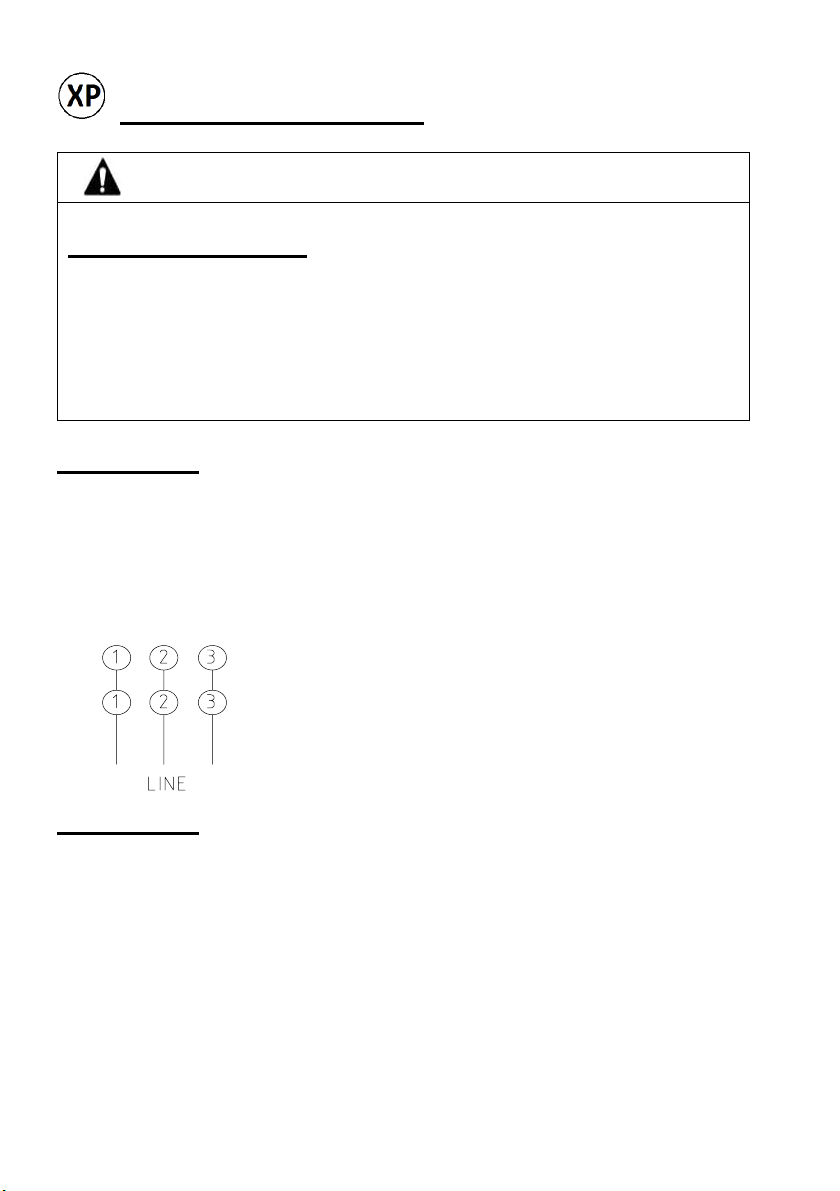
A motor with six leads shall be connected as follows:
1. Leads marked with the same number must be
connected to each other 1-1, 2-2 & 3-3.
2. Three pairs will be obtained. Each one shall be
connected to a different phase of the electrical supply.
IMPORTANT
If the motor was requested with a special connection, do not connect the motor
as described above. For further information and/or technical support, please
contact your local ABB sales office.
Note: All motor leads are marked according to NEMA MG1 standard, connections
must be done as diagram shown in nameplate, take in account that phases 1, 2
and 3 correspond to phases U, V and W respectively.
70 A5E52711437A_AA
Page 22

The motor might be supplied with an internal device protecting the windings
CAUTION
DANGER
against overheating and/or overload. The type of the protection device is specified
in the nameplate. A RTD (Resistance Temperature Detector) is placed on or inside
the windings to record its temperature. Leads of this device must be connected to
another device capable of interpreting the RTD signal to shut down the electrical
supply in case of overheating.
Overload protection devices act directly on the power circuit. They use
bimetallic materials which deform when a high and constant current passes through
them. E.g: The KLIXON's.
If the motor is equipped with an electrical heating element, it must have: an
adequate power supply, overload protection, and switching devices that ensure
that the heating element ONLY OPERATES WHEN THE MOTOR IS NOT
ENERGIZED.
If the motor is equipped with tachometer, safety and connection instructions
from the tachometer manufacturer shall be addressed before starting the motor
for the first time.
Installation and Start Up 8
1.- The installation, operation and maintenance of the motor shall be carried
out by qualified personnel, who must be familiar with codes, guidelines and
applicable local regulations. Personnel must use the adequate tools and be
experienced in installation, operation and maintenance of electric motor.
2.- Before any handling, make sure you have your personal safety
equipment such as shoes, gloves, girdle and lenses because if these
preventive measures are not taken, physical damage may occur.
3.- When working with voltage levels up to 600 V.A.C. and moving parts
(even at low speeds) there is the possibility to suffer serious injuries or death.
71 A5E52711437A_AA
Page 23
Before any repair or maintenance service, use electrical or mechanical locks
CAUTION
to prevent a sudden or unwanted startup of the motor.
1.- The motor shall be installed in an environment adequate for its design
and application features. Otherwise, the motor will have a deficient
performance and a reduced life. For further information please consult your
local ABB sales office.
2.- The motor foundation must rigidly support (Screwed) all four feet in the
same plane in order to avoid vibrations and maintain a correct alignment
between the motor shaft and the load. Shims can be used under the motor
feet. For direct drive, accurate alignment is 0.004 inch/ft. (radius to dial
indicator = one foot). Any change in shims requires rechecking alignment.
3.- When installing flat belt pulley, V-belt sheave, spur or helical pinion or
chain drives, be certain that they are within NEMA-MG1 limitations. Refer to
NEMA-MG1, Section II part 14.7 and Section II part 14.42. Protective covers
must be installed to prevent unwanted contact between moving parts and
other objects or personnel.
4.- Ensure that any optional supplementary motor monitoring equipment has
been connected correctly and is functioning as it should.
5.- It ensures a long life of the bearings maintaining proper alignment,
adequate tension in the band or chain and good lubrication at all times.
6.- Ensure that the cooling airflow is not obstructed or diminished in any
way and have enough free space for the correct operation of the motor.
7.- Prevent the air expelled by neighboring equipment from being
immediately sucked in again.
8.- For motors with a vertical type construction with air entry from above,
prevent the ingress of foreign bodies and water in the air entry openings.
72 A5E52711437A_AA
Page 24

CAUTION
Nominal
Danger caused by inappropriate fasteners material
If screws of an incorrect property class have been selected or if have
been fastened to an incorrect tightening, they may break or become loose.
This will cause the motor to move, which could damage the bearing. The
motor could smash into de motor enclosure and motor parts could be flung
out of place. This can result in death, serious injury or material damage
• Comply with the required property classes for screws connections.
• Tighten the screwed connections to de specified tightening torques.
Tightening torques in motors
All screws tightening torques for screws in threaded joints of
bearing shields, housing and bearing caps should have the following
torques according to the size of the screw.
Hexagonal screw head grade 5
Diameter
(Inches)
5/32" 32 3.1 3.5 3.8
3/16" 24 4.4 4.9 5.4
1/4" 20 10.7 11.9 14.2
5/16" 18 21.7 24.2 29.2
3/8" 16 38.2 42.5 47.0
7/16" 14 61.0 67.9 75.0
1/2" 13 92.0 103.0 114.0
5/8" 11 184.0 204.0 224.4
3/4" 10 322.0 358.0 393.0
7/8" 9 450.0 490.0 520.0
Threads per inch
73 A5E52711437A_AA
Minimum
(Nm)
(Nm)
Maximum
(Nm)
Page 25

Torque values for fan covers and deflector assembly
Nominal
Nominal
Hexagonal screw head grade 5
Diameter
(Inches)
3/16" 24 3.0 3.5 3.8
3/16" 24 3.0 3.5 3.8
3/16" 24 3.5 4.0 4.5
1/4" 20 8.0 10.0 13.0
3/8" 16 20.0 24.0 28.0
3/8" 16 25.0 30.0 35.0
7/16" 14 50.0 55.0 60.0
7/16" 14 55.0 60.0 65.0
3/8" 16 18.0 22.0 26.0
3/8" 16 20.0 24.0 28.0
3/8" 16 25.0 30.0 35.0
Threads per
inch
Minimum
(Nm)
(Nm)
Maximum
(Nm)
Torque values for terminal boxes assembly
Hexagonal screw head grade 5
Diameter
(Inches)
1/4" 20 5.0 7.5 10.5
5/16" 18 11.0 14.0 17.0
3/8" 16 16.0 20.0 24.0
1/2" 13 21.0 26.0 30.0
Threads per
inch
Minimum
(Nm)
(Nm)
Maximum
(Nm)
74 A5E52711437A_AA
Page 26

Cooling and Air Guidance
INCORRECT CORRECT
Minimum dimension X=5” for the distance between neighboring modules and the
air intake of the motor.
75 A5E52711437A_AA
Page 27

CAUTION
All wiring to the motor, size of the conductors, drivers, protection devices,
WARNING
motor starters, grounding devices and any other electrical equipment must be in
accordance with NOM-001-SEDE, NEC and the National Electrical Code and all
local regulations.
Electrical supply must meet the values of voltage and frequency described in
the motor nameplate. The motor will operate successfully under running
conditions at rated load with a variation in the voltage or the frequency up to the
following:
1. When the variation in the voltage value does not exceed 10% above or
below the specified in the motor nameplate, with all phases balanced.
2. When the variation in the frequency value does not exceed 5% above
or below the specified in the motor nameplate.
3. When the sum of the voltage and the frequency values does not exceed
10% above or below the specified in the motor nameplate (provided
frequency value variation does not exceed the 5%).
However, performance within these voltage and frequency variations will not
necessarily be in accordance with the standards established for operation at
rated voltage and frequency.
Any electrical maneuver must be carried out by qualified personnel, taking
the following warnings into consideration:
1. The electrical supply shall be disconnected and preventive action
against accidental connection must be taken.
2. The motor shall be properly connected to a grounding circuit. Refer to
the NOM-001-SEDE and NEC or any other local electrical code.
76 A5E52711437A_AA
Page 28
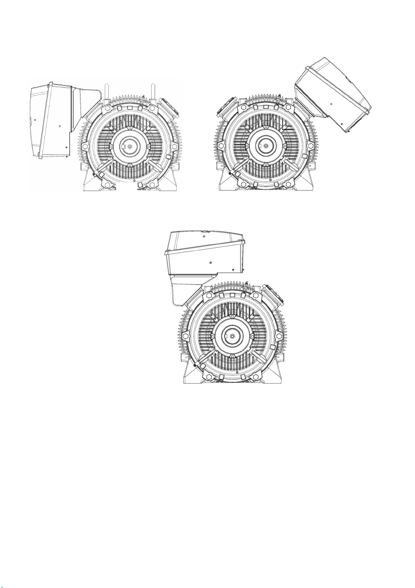
Mounting options for terminal box in motors type SD200
Top mounting on motor
Standard mounting Mounting to 45°
77 A5E52711437A_AA
Page 29

WARNING
Danger of falling components in the change of mounting
type F1 to F2 either box on the motor or box at 45 °
To change the configuration from F1 to F2 in frame 500 and given the
weight of the components to be moved, the following safety instructions
must be carried out.
Connection box base
2.1.- Remove the two lateral plastic plugs that are on the sides of the
connection box base where the threaded holes are for this purpose.
2.2.- Place a 3/8 "-16 NC eye bolt on each side of the connection base.
(See the following figure)
2.1.- Once the two eyebolts are in place, proceed to slightly tighten the
lifting system by slings and / or chains. (Optional).
2.2.- Proceed to remove all the fixing screws of the base with the
housing until its complete release and move slowly to the other side of the
motor for its placement and proceed to fix in its new position.
2.3.- Once the base has been placed in its new location remove the two
eyebolts and replace the protective plastic plugs.
Use eyebolts in placed laterally to the terminal base for
removal and change of position F1 to F2.
78 A5E52711437A_AA
Page 30

CAUTION
Do not insert screwdrivers or wedges between the base and the cover of the
CAUTION
explosion proof conduit box. Doing so could affect the tight fit between the base
and the cover which may compromise the explosion proof properties of the
motor.
To remove the cover of the explosion proof conduit box, first loosen
the screws, but do not remove them completely in order to prevent the
cover from sliding or falling. Then use a couple levers in the notches
provided, as shown in the illustration. Failure to follow these instructions
might result in serious injuries and/or damage to the motor and its
surroundings.
If the operation of the motor with a variable frequency drive (VFD) is
necessary, the readings listed in the standard NEMA-MG1 Section 4 Part 31, or
in the NEMA MG2-Section 6 must be addressed. In addition:
79 A5E52711437A_AA
Page 31

1. Variable frequency drive must be properly selected, according to the
WARNING
NEMA
NEMA
power of the motor and the conditions of the electrical supply (such as
number of phases, voltage, and current capacity).
2. Connect the motor, the VFD, metal conduit and any metal part to an
independent grounding circuit. The VFD must be mounted as close as
possible to the motor.
3. Use conductor with the appropriate gauge, the shortest possible length
and canalized through metal conduits. In addition, the conductors can
be shielded to reduce electromagnetic interference with electronic
equipment.
4. The operation of a motor with a VFD causes an increase in operating
temperature which in turn leads to the deterioration of the insulation on
the windings.
Always attend the safety instructions of the VFD manufacturer. High AC and
DC voltages are present in a VFD even after the VFD is de-energized. See VFD
operation manual to avoid personnel injury.
In order not to affect the optimal functioning of the motor-VFD system and to
ensure proper insulation; the length of the power leads from the VFD to the motor
shall not exceed those listed in Table 1.1. Maximum power leads length from
VFD output to motor.
Frame Size 230 V 460V 575V
143-320
360-449
Table 1.1 Maximum power lead length from VFD output to motor.
80 A5E52711437A_AA
600 ft.
100 ft.
125 ft. 40 ft.
225 ft. 60 ft.
Page 32

CAUTION
A proper programming of the parameters of the VFD is of the utmost
WARNING
importance. Please read and understand the VFD manufacturer's instructions
manual. Use the data on the motor nameplate. VFD Programming should be
performed by qualified personnel only. For further information and/or technical
support, please consult your local ABB sales office.
If the motor is equipped with tachometer, safety and connection instructions
from the tachometer manufacturer shall be addressed before starting the motor
for the first time.
Measures to take when commissioning
explosion-proof motors
After installation or inspections, the following measures are recommended for
normal start-up of the machines:
● Start the machine without a load; to do this, close the motor starter
protector and do not switch the machine off prematurely.
● You should limit how often you switch the machine off while it is starting
up and still running at a slow speed, for checking the direction of rotation or the
required dimensions, for example.
● Allow machines to reach a standstill before switching them back on.
Operation 9
Before starting the motor for the first time make sure that all the previously
stated recommendations are fulfilled.
Before starting the motor, check that all the screws and rotating parts are
correctly positioned and tightened. The use of protective covers in rotating parts
is suggested. Make sure that the electrical connections are correct, and that
81 A5E52711437A_AA
Page 33

leads are firmly attached and sufficiently insulated for the operating voltage
WARNING
levels.
If a reduced voltage start method is to be used, it is important to consider
that the torque output will be lower in the same proportion. For further information
and/or technical support on our motor starting solutions, please consult your local
ABB sales office.
Before starting the motor for the first time, make sure that the
recommendations mentioned above are complied with.
1.- The first startup of the motor must be done without any load or mechanism
connected to motor’s shaft. Parameters such as current, voltage, power
consumption and temperature shall be measured and compared against
nameplate data. Check direction of rotation. If the motor is energized, but
this does not start or if vibration, noise or excessive current draw are present,
immediately switch off electrical supply. Investigate and correct the failure. If
the motor is equipped with roller bearings on the drive end this first startup
must be brief in order to avoid damage to the bearings.
2.- The use of electronic devices to achieve soft starts is recommended to
avoid high values of current during startup.
3.- If a reduced voltage start method is to be used, it is important to consider
that the torque output will be lower in the same proportion. For further
information and/or technical support on our motor starting solutions, please
consult your local ABB sales office.
4.- Check the mechanical operation for noises or vibrations at the bearings
and bearing end shields.
5.- Monitoring the electrical and temperature values during initial and
subsequent operation to verify correct operation.
6.- Verify in a reasonable period the voltages values of the line (High / Low)
and evaluate those conditions.
7.- Verify that the protective guards and hoppers of the parts in movement
are well insured to avoid accidents.
82 A5E52711437A_AA
Page 34

CAUTION
Repeated trial starts can overheat the motor and may result in motor
WARNING
burnout (particularly for across the line starting). If repeated trial starts are made,
allow sufficient time between trials to allow heat to dissipate from windings and
rotor to prevent overheating.
Hot surfaces
Electric machines have hot surfaces. Do not touch these surfaces. They
could cause burns.
• Allow the machine to cool before starting work on the machine.
• Only remove the covers using the methods described by these operating
instructions.
Danger of explosion
If the anti-condensation heating is switched on directly after the motor
is switched off, the temperature class or the maximum surface temperature
of the motor can be exceeded.
In an explosive atmosphere, there is a high risk of an explosion. This
can result in death, serious injury or material damage.
Do not switch on the anti-condensation heating for at least one hour
after the motor has been switched.
WARNING
83 A5E52711437A_AA
Page 35

WARNING
Risk of explosion due to excessive bearing temperature
WARNING
The surface temperature cannot be maintained within the maximum
permissible limits if the bearings become too hot. The dust can ignite,
resulting in an explosion. This can result in death, serious injury or material
damage.
• Always check the bearing temperature.
• In addition to the current-dependent overload protection device
located in the three phases of the connecting cable, we recommend that you
also monitor the temperature rise in the motor with the aid of the
temperature sensors integrated built into the stator winding.
Overheating of roller bearing
If roller bearings are not regularly re-greased, local overheating may be
possible, and, as a consequence, an explosion in an explosive atmosphere.
This can result in death, serious injury or material damage.
• Re-grease the roller bearings regularly according to the lubrication table.
• Implement bearing temperature monitoring if not yet in existence.
Operation temperature
The electric motors still operating under normal conditions reach high
temperatures. This is why motors are designed to withstand high temperatures, and
although some places may feel hot to the touch, the motor may be operating within
the limits. Use a thermocouple to measure the temperature in the winding when
there is any concern about it.
The total temperature, not the temperature rise, is the measure of safe
operation. Investigate the winding operating conditions. The total temperature
should not exceed of:
84 A5E52711437A_AA
Page 36

WARNING
230°F (110°C) for class “B” insulation
275°F (135°C) for class “F” insulation
302°F (150°C) for class “H” insulation
Safety information for explosion-protected
motors in operation
Explosion hazard
These explosion-protected machines are not suitable for hybrid explosive
environments.
This can result in death, serious injury or material damage.
Use in atmospheres where there is a risk of explosion caused by both gas
and dust simultaneously is absolutely prohibited.
Only install motors for Zone 2 in hazardous areas, according to the
regulations laid down by the responsible regulatory body. They are responsible
for determining the hazard level of each area (division 2 zones).
● If there are no other specifications examination certificates or on the
rating plate regarding operating mode and tolerance, electrical machines are
designed for continuous duty and normal starting procedures that are performed
infrequently and do not result in excessive temperature rise. Only use these
machines for the operating mode specified on the rating plate.
Safety instructions for cleaning
To ensure problem-free machine cooling, the air ducts (ventilation grilles,
channels, cooling fins, tubes) must be free of pollution.
85 A5E52711437A_AA
Page 37

WARNING
Risk of explosion when cleaning with compressed air
CAUTION
If you clean the machine with compressed air, plastic components may
become statically charged and ignite a potentially explosive atmosphere; an
explosion can occur. This can result in death, serious injury or material
damage.
• Do not use compressed air to clean motors when installed in hazardous
zones!
Maintenance 10
Failure to properly maintain the equipment can result in severe personal
injury and product failure. The instructions contained herein should be carefully
reviewed, understood and followed. If the corrrect tools are not available or a
major maintenance is required, it must be carried out only by personnel
authorized by ABB. Please contact your local ABB sales office for more
information our comprehensive maintenance solutions.
Following maintenance procedures must be performed regularly:
1. Bearing lubrication.
2. Winding insulation resistance check.
3. Cleaning.
This checklist does not represent an exhaustive survey of maintenance steps
necessary to ensure safe operation of the equipment. Particular applications
may require further procedures. Should further information be desired or should
particular problems arise which are not covered sufficiently for the purchaser’s
purposes, the matter should be referred to the local ABB sales office.
86 A5E52711437A_AA
Page 38

WARNING
Dangerous voltages are present in the motor which can cause severe personnel
CAUTION
injuries. Always disconnect and ground the equipment before maintenance.
Maintenance should be performed only by qualified personnel
The use of unauthorized parts in the repair of the equipment, tampering by
unqualified personnel, or removal or alteration of guards or conduit covers will
result in dangerous conditions which can cause severe personal injury or
equipment damage. Follow all safety instructions contained herein.
Lubrication
Prior to shipment, motor bearings are lubricated with the proper amount and
grade of grease to provide six months of satisfactory service under normal
operation and conditions.
After that period, the motor must be lubricated as recommended in Table 1.2:
Lubrication frequencies, where, in a general way, time intervals have been
established according to the service and atmosphere in which the motor operates.
For further information, please consult your local ABB sales office.
Lubrication
frequency
6 Months Moderate service/ Clean and dry atmosphere
3 Months
Table 1.2 Lubrication frequencies.
Note: General purpose motors (up to FS250) and low maintenance motors are
provided with lubricated for life bearings, these bearings should be replaced at the
end of the grease service life.
Service/ Operation Atmosphere
Severe service/ Adverse atmospheres, dust,
moisture and vibrations
87 A5E52711437A_AA
Page 39

Grease
CAUTION
For standard motors, grease should be compounded from a Polyurea base and
a good grade of petroleum oil. It should be of No. 2 consistency and stabilized
against oxidation. Operating temperature range should be from -15°F to +250°F for
class “B” insulation, and to +300°F for class “F” and “H”. Most leading oil companies
have special bearing greases that are satisfactory.
Insert the new grease to be placed is equivalent and above all, compatible
with the original grease.
Lubrication procedure
The motor can be lubricated while running or stopped. It is advisable to do so while
the motor is stopped, for which the following procedure must be followed:
1. Take the necessary actions to prevent unexpected starts. (DISCONNECT
THE SYSTEM). Clean the grease fitting and remove the drain plug from
the grease outlet.
2. Remove the old hardened grease from inlets and outlets. Use a stiff wire
or rod.
3. If necessary, remove the nipples and fittings, clean, and reinstall.
4. With a low pressure grease gun, add half the required amount of new
grease.
5. Run the motor for 5 minutes to distribute the grease. Then stop it and add
the rest of the lubricant.
6. Install the drain plug in the grease outlet and wipe away the excess of
grease.
Verify motor grease type and only re-lubricate with compatible type of
grease. Mixing greases of different bases (lithium, clay, polyurea, etc.) will cause
bearing failure or malfunction and should not be done. All non-compatible grease
must be removed from the bearings and housings when making a grease
change. Excess grease in the motor can cause damage to the bearings; check
Table 1.3 of Grease Quantities, for the necessary grease quantities according to
the motor frame size.
88 A5E52711437A_AA
Page 40

Grease Quantity per End
-
Shield
side
(oz)
NEMA Frame Drive End.
Opp. Drive
End.
1400.20.2
1800.50.5
2100.60.6
250
1.1
1.1
280
1.5
1.5
320
2.5
2.5
360
3.7
3.7
400
5.6
5.6
440
9.4
8.7
S449
9.4
8.7
50016.4
16.4
Table 1.3 Grease Quantities.
Vertical motors thrust bearings
Top bearings
High external thrust from the driven unit is usually carried by the top bearing
or bearings. If replacement is necessary, the new bearing must be the same size
and type as the original.
Duplex bearings must also be the same type and mounted in an identical manner.
When angular contact type bearings are replaced, the new bearing must have the
same thrust capacity.
Bottom bearings
For an adequate lubrication It is important to maintain the lower cavity full of
grease at all times.
The re-lubricating procedure for vertical motors is the same as outlined above
under “Lubrication procedure”.
The correct replacement bearings are given on the nameplate by AFBMA
(Anti-Friction Bearing Manufacturers Association) number.
89 A5E52711437A_AA
Page 41

Insulation resistance measurement
WARNING
CAUTION
Measure insulation resistance and register it periodically (approx. every
5000 operating hours). A portable insulation meter (Megger) for 500 DCV is the
most convenient and safest method. According to IEEE (Institute of Electrical and
Electronics Engineers) standards, the insulation resistance at 75°C measured at
500 V.D.C. after one minute should be not less than:
Nominal motor voltage + 1000=Insulation resistance in Mega ohms
1000
This formula is satisfactory for most of the checks. For more information see
IEEE standard No. 43 “Recommended Practice for Insulation Resistance Testing
of AC Rotating Machinery”.
High DC voltage levels are used during this test. Therefore, severe injuries
can be caused if tests are not carried out by qualified personnel with adequate
tools.
Cleaning and draining
All surfaces of the motor must stay free of oil, dust, dirt, moisture, chemical
agents, or any other accumulation that would provoke a faulty cooling of the
equipment. For fan cooled motors, it is particularly important to keep the air
intake openings free of foreign material. Do not block air outlet or inlet. The motor
(excluding explosion proof models) has a removable plug, in the low part of the
housing, which allows draining accumulated humidity. Drain regularly.
Additional painting
Please contact your local ABB sales office for information about additional painting.
90 A5E52711437A_AA
Page 42
Motor disposition
WARNING
WARNING
Your motor has materials that can be recovered or recycled. The right
separation of materials helps with an easy recycling of important materials. Leave
your equipment or electrical product at a collection point. Contact your local
authorities for more information on disposal of electrical equipment.
Repair of paint damage
Note
Contact the Service Center before you repair any paint damage. They will
provide you with more information about the correct paint system and methods of
repairing paint damage.
Explosion hazard caused by incorrect painting
The paint coat can become electrostatically charged where there is a thick
coat. Electrostatic discharges can occur. There is a risk of explosion if
potentially explosive mixtures are also present at this moment. This can result
in death, serious injury or material damage.
Repair work
Take into account, in all work carried out on the motor, the general safety
instructions.
Explosion hazard when carrying out repair work
Repairs are only permissible within the scope of the work described in
these operating instructions. Otherwise an explosion can occur in an
explosive atmosphere. This can result in death, serious injury or material
damage.
91 A5E52711437A_AA
Page 43

For repairs to go beyond this scope, please contact the Service Center.
Fan cover
Explosion hazard due to high temperature at surface
Components within the motor may be hotter than the maximum
permissible surface temperature for the enclosure. In an explosive
atmosphere, dust can ignite, and an explosion occurs. This can result in
death, serious injury or material damage.
• Do not open the motor in an explosive and dusty atmosphere when it is still
at normal operating temperature.
• Allow the machine to cool down before opening it.
Replacing bearings
Before to place single shielded bearings, take care to put shielded side of
bearings at opposite side of greasing hole. This to ensure the right lubrication of
the bearing.
Replacing bearings in explosion-proof motors
● When changing the bearings, renew the sealing rings and only use
original ABB spare parts.
● For radial sealing rings with dust protection lip (DIN 3760-AS),
completely fill the spaces (100%) in the sealing ring as well as in the bearing
shield hub with a suitable grease.
Note
For explosion-proof motors, only use spare parts and original repair parts.
WARNING
Danger of falling parts while changing bearings
In large frames and due to the weight of the components to be extracted,
the following safety instructions must be carried out.
1.-
It is necessary to use synthetic flat slings with a capacity
92 A5E52711437A_AA
Page 44

greater than 150 kilograms for the adequate lifting of the fan cover.
1.1.- Remove the protective cover from the fan cover and proceed to
pass the flat sling so that it completely supports the fan cover.
1.2.- Lightly tighten the lifting system with the sling and proceed to
remove the fastening screws of the cap until its complete release.
2.- Endshields For the safe extraction of the end shields or C flanges, it
will be carried out in the following way:
2.1.- Slightly loosen all the fastening screws with the housing in such a
way that when removing one of the upper screws it can be replaced by an
eyebolt which will be placed in the hole of the eye using a nut on the
opposite side of the eye bolt and fixed.
2.2.- Lightly tighten the lifting system and proceed with the extraction of
the rest of the screws with the housing and slowly move the shield outwards
until it is completely removed (be careful not to hit the shaft in the
extraction).
Spare parts 11
For ordering parts
1. - For orders of spare parts or parts for repair, the following information is
needed:
● Name of the piece
● Motor reference and serial number, (It is indicated on the name plate of
the motor).
2. - Contact any of our distributors in Mexico, USA and Canada, they are
authorized and trained to process your requirement of the parts that need your
motor.
3. - Additionally, you can also contact our customer service and support in
replacement parts and / or spare parts.
Disposal 12
Introduction
Protecting the environment and preserving its resources are corporate goals
of the highest priority for us. Our worldwide environmental management system to
ISO 14001 ensures compliance with legislation and sets high standards in this
93 A5E52711437A_AA
Page 45
regard. Environmentally friendly design, technical safety and health protection are
always firm goals even at the product development stage.
Recommendations for the environmentally friendly disposal of the machine
and its components are given in the following section. Be sure to comply with
local disposal regulations.
Preparing for disassembly
Disassembly of the machine must be carried out and/or supervised by
qualified personnel with appropriate expert knowledge.
1. Contact a certified waste disposal organization in your vicinity. Clarify what is
expected in terms of the quality of dismantling the machine and provision of the
components.
2. Follow the five safety rules.
2.1.- Disconnect the system. Also disconnect the auxiliary circuits, for
example, anti-condensation heating.
2.2.- Secure against reconnection.
2.3.- Verify absence of operating voltage.
2.4.- Ground and short-circuit.
2.5.- Provide protection against adjacent live parts.
To energize the system, apply the measures in reverse order.
3. Disconnect all electrical connections and remove all cables.
4. Remove all liquids such as oil and cooling liquids. Collect the liquids separately
and dispose of them in a professional manner.
5. Detach the machine fixings.
6. Transport the machine to a suitable location for disassembly.
Motor disassembly
Disassemble the motor using the general procedures commonly used in
mechanical engineering.
94 A5E52711437A_AA
Page 46
WARNING
Machine parts can fall
1.- The machine is made up of heavy parts. These parts are liable to fall
during dismantling. This can result in death, serious injury or material damage.
2.- Before you release any machine parts, secure them so that they cannot
fall.
3.- Take care when disassembling the motor since there are sharp parts that
can cause bodily injury.
Disposal of components
Components
The machines consist mainly of steel and various proportions of copper and
aluminum. Metals are generally considered to be unlimitedly recyclable.
Sort the components for recycling according to whether they are:
● Iron and steel
● Aluminum
● Non-ferrous metal, e.g. windings, the winding insulation is
incinerated during copper recycling.
● Insulating materials
● Cables and wires
● Electronic waste
Process materials and chemicals
Sort the process materials and chemicals for recycling according to whether they
are for example:
● Oil
● Grease
● Cleaning substances and solvents
● Paint residues
● Anti-corrosion agent
● Coolant additives such as inhibitors, antifreeze or biocides
Dispose of the separated components according to local regulations or via
a specialist disposal company. The same applies for cloths and cleaning
substances which have been used while working on the motor.
95 A5E52711437A_AA
Page 47
Information according to article 33 of the Reach
regulation
This product contains one or several sub products in which the following
substance – belonging to the "list of candidates" – exists in a concentration
exceeding 0.1 percent by weight.
CAS No. 7439-92-1, Lead.
Based on the currently available information, we assume that this substance
does not represent any risk when correctly used, including its disposal.
Packaging material
If necessary, contact a suitable specialist disposal company.
Wooden packaging for sea transport consists of impregnated wood.
(Observe the local regulations).
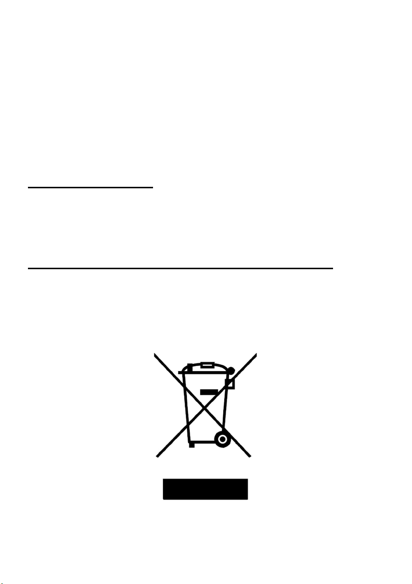
Motor disposition once productive life finished
Your motor has materials that can be recovered or recycled. The right
separation of materials helps with an easy recycling of important materials. Leave
your equipment or electrical product at a collection point. Contact your local
authorities for more information on disposal of electrical equipment.
DO NOT PUT IN TRASH CONTAINERS
96 A5E52711437A_AA
Page 48

Technical Service 13
For questions or technical support, contact your local technical support team
https://new.abb.com/contact-centers
Visit our website to learn more about products and services.
https://new.abb.com/motors-generators
For this, have the following data available:
● Type
● Serial number
This information is described on the name plate.
Notes
___________________________________________________________
___________________________________________________________
___________________________________________________________
___________________________________________________________
___________________________________________________________
___________________________________________________________
___________________________________________________________
___________________________________________________________
___________________________________________________________
___________________________________________________________
___________________________________________________________
___________________________________________________________
___________________________________________________________
97 A5E52711437A_AA
 Loading...