

Page 1

2TMD041800D0010│30.03.2019
Product manual
ABB-Welcome IP
H81381P.-. IP pushbutton outdoor
station
H81381P.-.-02 IP pushbutton outdoor
station
Page 2

Table of contents
2
Table of contents
1 Notes on the instruction manual .................................................................................................................... 3
2 Safety ............................................................................................................................................................. 3
3 Intended use .................................................................................................................................................. 4
4 Environment ................................................................................................................................................... 5
4.1 ABB devices ....................................................................................................................................... 5
5 Product description ........................................................................................................................................ 6
5.1 Control elements ................................................................................................................................ 6
5.2 Interfaces ............................................................................................................................................ 7
5.3 Locks and connections ...................................................................................................................... 8
6 Technical data ............................................................................................................................................... 9
7 Mounting/Installation .................................................................................................................................... 10
7.1 Requirement for the electrician ........................................................................................................ 10
7.2 Mounting ........................................................................................................................................... 11
7.2.1 Preparation .....................................................................................................................................11
7.2.2 Wiring ..............................................................................................................................................11
7.2.3 Surface-mounted installation ..........................................................................................................12
7.2.4 Flush-mounted installation .............................................................................................................12
7.2.5 Cavity wall installation ....................................................................................................................14
7.2.6 Dismantling .....................................................................................................................................15
7.2.7 Replacing the nameplate ................................................................................................................15
8 Commissioning ............................................................................................................................................ 16
9 Operation ..................................................................................................................................................... 18
9.1 Calling a resident ............................................................................................................................. 18
9.2 Calling the guard unit ....................................................................................................................... 18
9.3 Turn on the light ............................................................................................................................... 19
10 FCC .............................................................................................................................................................. 20
11 Cyber security .............................................................................................................................................. 21
11.1 Disclaimer ......................................................................................................................................... 21
11.2 Performance and service ................................................................................................................. 21
11.3 Deployment guideline ...................................................................................................................... 22
11.4 Upgrading ......................................................................................................................................... 22
11.5 Backup/Restore ................................................................................................................................ 22
11.6 Malware prevention solution ............................................................................................................ 22
11.7 Password rule .................................................................................................................................. 22
Product manual 2TMD041800D0010 │
Page 3

Notes on the instruction manual
3
1 Notes on the instruction manual
Please read through this manual carefully and observe the information it contains. This will
assist you in preventing injuries and damage to property, and ensure both reliable operation and
a long service life for the device.
Please keep this manual in a safe place. If you pass the device on, also pass on this manual
along with it. ABB accepts no liability for any failure to observe the instructions in this manual.
2 Safety
Warning
Electric voltage!
Dangerous currents flow through the body when coming into direct or indirect
contact with live components.
This can result in electric shock, burns or even death.
– Disconnect the mains power supply prior to installation and/or disassembly!
– Permit work on the 100-240 V supply system to be performed only by
specialist staff!
Product manual 2TMD041800D0010 │
Page 4

4
3 Intended use
As part of the ABB-Welcome IP system, this device can only be used with accessories from that
system.
Security mode
This outdoor station runs in "Security mode" by default to guarantee high security.
In "Security mode", this outdoor station requires a certificate issued by the management
software before it can function normally.
Compatible mode
If there is no management software, this outdoor station needs to run in "Compatible mode" to
function normally. This can be set on the indoor station. Please refer to the product manual for .
IP touch 7".
Video privacy
Intended use
Video privacy
Making and saving video recordings can infringe on personal rights! Always
observe the applicable legal and labeling requirements for the placement and
operation of video components!
Product manual 2TMD041800D0010 │
Page 5

5
4 Environment
Consider the protection of the environment!
Used electric and electronic devices must not be disposed of with household
waste.
– The device contains valuable raw materials that can be recycled. Therefore,
dispose of the device at the appropriate collecting facility.
4.1 ABB devices
All packaging materials and devices from ABB bear the markings and test seals for proper
disposal. Always dispose of the packing materials and electric devices and their components via
an authorized collection facility or disposal company.
ABB products meet the legal requirements, in particular the laws governing electronic and
electrical devices and the REACH ordinance.
(EU-Directive 2012/19/EU WEEE and 2011/65/EU RoHS)
(EU-REACH ordinance and law for the implementation of the ordinance (EG) No.1907/2006)
Environment
Product manual 2TMD041800D0010 │
Page 6

Product description
6
5 Product description
4
5.1 Control elements
No. Function
1 Camera
1
2
3
2 Speaker and microphone integration
3 Round pushbutton
4 End strip
Product manual 2TMD041800D0010 │
Page 7

Product description
7
5.2 Interfaces
2 3
1
10
4
5
6
11
7
9
8
7
No. Function
1 Reset button
2 Micro USB update connector
3 Plug-in clamps (DC+...GND) for standalone power supply
4 Plug-in clamps (LOCK...GND) for door opener
5 Plug-in clamps (COM...NC...NO) for floating output, door opener
6 LAN (PoE)
7 Connector for next module
8 Connector for exit button
9 Connector for the sensor used for door status detection
10 Connector for 5" display module
Product manual 2TMD041800D0010 │
11 Connector for previous module
Page 8

Product description
8
5.3 Locks and connections
Lock type Pic Operation type Voltage Wiring type
Electrical strike
lock, 12V
Electrical strike
lock, 24V
Electrical rim
lock, 12 V
Electrical
mortise lock
Magnetic lock
Power on to open
Power on to open
Power on to open
Power off to open
Power off to open
12
VDC/AC
24
VDC/AC
12 VDC
12 VDC
12/24 V
DC
Type A
Type B
Type B
Type A
Type B
Type C
Type C
Product manual 2TMD041800D0010 │
Page 9

9
6 Technical data
Designation Value
Rating voltage 24 V DC
Operating voltage range 20-27 V DC
Rating current
Operating temperature -40 °C…+55 °C
Product dimensions 135mm x 276.9 mm × 17.6 mm
Camera type CMOS
Camera viewing angle 130°
Resolution ratio HD (1280 x 720 pixel)
Power supply for door opener 18 V, 4 A impulse, max. 250 mA holding
Floating output for door opener
Video codec H.264
Technical data
27 V DC, 300 mA
24 V DC, 330 mA
230 V AC, 3 A
30 V DC, 3 A
Audio codec G.711
IP level IP 54
IK level IK 07
Network connection standard IEEE 802.3, 10Base-T/100Base-TX, auto MDI/MDI-X
Product manual 2TMD041800D0010 │
Page 10

Mounting/Installation
10
7 Mounting/Installation
Warning
Electric voltage!
Dangerous currents flow through the body when coming into direct or indirect
contact with live components.
This can result in electric shock, burns or even death.
– Disconnect the mains power supply prior to installation and/or disassembly!
– Permit work on the 100-240 V supply system to be performed only by
specialist staff!
7.1 Requirement for the electrician
Warning
Electric voltage!
Install the device only if you have the necessary electrical engineering
knowledge and experience.
– Incorrect installation endangers your life and that of the user of the electrical
system.
– Incorrect installation can cause serious damage to property, e.g. due to fire.
The minimum necessary expert knowledge and requirements for the installation
are as follows:
– Apply the "five safety rules" (DIN VDE 0105, EN 50110):
1. Disconnect
2. Secure against being re-connected
3. Ensure there is no voltage
4. Connect to earth and short-circuit
5. Cover or barricade adjacent live parts.
– Use suitable personal protective clothing.
– Use only suitable tools and measuring devices.
– Check the type of supply network (TN system, IT system, TT system) to
secure the following power supply conditions (classic connection to ground,
protective grounding, necessary additional measures, etc.).
Product manual 2TMD041800D0010 │
Page 11

11
7.2 Mounting
7.2.1 Preparation
Use gloves to protect yourself against cuts.
7.2.2 Wiring
Mounting/Installation
Product manual 2TMD041800D0010 │
Page 12
Mounting/Installation
12
7.2.3 Surface-mounted installation
2
6
4
m
m
40 mm
211 mm
6
32 mm
71 mm
1X3
4
5
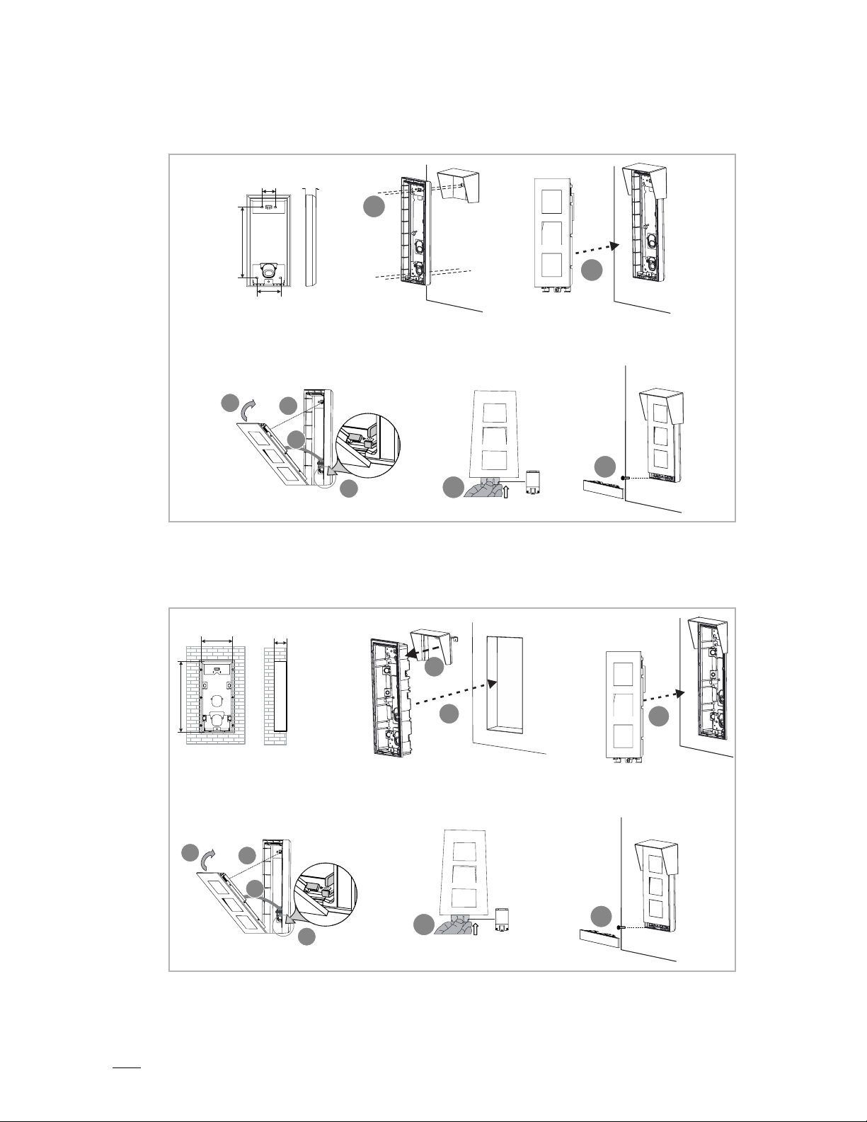
7.2.4 Flush-mounted installation
1. Flush-mounted without pre-installation box
1
2
8
3
7
117 mm
7
1X3
46 mm
1
2
5
6
4
8
9
3
Product manual 2TMD041800D0010 │
Page 13

Mounting/Installation
13
2. Flush-mounted with pre-installation box
2
7
4
m
m
126 mm
68 mm
2
1X3
1
3
8
6
7
4
5
10
9
Product manual 2TMD041800D0010 │
Page 14

Mounting/Installation
14
7.2.5 Cavity wall installation
1
3
2
5
4
6
8
6
7
10
9
5
Product manual 2TMD041800D0010 │
Page 15

15
7.2.6 Dismantling
7.2.7 Replacing the nameplate
Mounting/Installation
2
Installation situations
Note
The following installation situations must be avoided without fail to ensure
picture quality:
■
Direct light
■
Direct sunlight
■
Extremely bright picture background
■
Highly reflective walls on the opposite side of the door station
■
Lamps or direct light sources
1
3
Product manual 2TMD041800D0010 │
Page 16

16
8 Commissioning
The outdoor station must be configured via the indoor station.
Step1: Outdoor station enters engineering mode
■
Power on the outdoor station, wait a while until all 3 LED indicators go out.
■
Hold the first button on the outdoor station for 10 s until all 3 LED indicators start to flash.
Tip
The outdoor station will quit engineering mode after 5 minutes.
Step 2: Indoor station enters engineering mode
On the extra screen on the indoor station, click "System" to enter the settings screen.
Commissioning
Product manual 2TMD041800D0010 │
Page 17

Commissioning
17
On the "System settings" screen, click "Engineering settings", enter the engineering password
(default is 345678) to enter the settings page.
Step3: Indoor station configures outdoor station
On the "Engineering settings" screen, click "Outdoor station settings" to configure the outdoor
station.
Please refer to the product manual for the IP touch 7".
Product manual 2TMD041800D0010 │
Page 18

Operation
18
9 Operation
9.1 Calling a resident
Press the button to start a call (default) and press again to restart the call.
9.2 Calling the guard unit
If the outdoor station has been configured via the indoor station, we can press the pushbutton to
call the designated guard unit. Please refer to the product manual for the IP touch 7".
Product manual 2TMD041800D0010 │
Page 19

Operation
19
9.3 Turn on the light
If the outdoor station is configured by the indoor station, we can press the pushbutton to switch
on the light connected to the IP actuator. Please refer to the product manual for the IP touch 7".
Product manual 2TMD041800D0010 │
Page 20

FCC
20
10 FCC
This device complies with Part 15 of the FCC Rules. Operation is subject to the following two
conditions: (1) this device may not cause harmful interference, and (2) this device must accept
any interference received, including interference that may cause undesired operation.
Only operate the device in accordance with the instructions supplied.
Changes or modifications to this unit not expressly approved by the party responsible for
compliance could void the user’s authority to operate the equipment.
NOTE: This equipment has been tested and found to comply with the limits for a Class B digital
device, pursuant to part 15 of the FCC Rules. These limits are designed to provide reasonable
protection against harmful interference in a residential installation. This equipment generates,
uses and can radiate radio frequency energy and, if not installed and used in accordance with
the instructions, may cause harmful interference to radio communications. However, there is no
guarantee that interference will not occur in a particular installation. If this equipment does
cause harmful interference to radio or television reception, which can be determined by turning
the equipment off and on, the user is encouraged to try to correct the interference by one or
more of the following measures:
– Reorient or relocate the receiving antenna.
– Increase the separation between the equipment and receiver.
– Connect the equipment into an outlet on a circuit different from that to which the receiver is
connected.
– Consult the dealer or an experienced radio/TV technician for help.
Product manual 2TMD041800D0010 │
Page 21

21
11 Cyber security
11.1 Disclaimer
H81381P.-. products are designed to be connected and to communicate information and data
via a network interface, which should be connected to a secure network. It is customer‘s sole
responsibility to provide and continuously ensure a secure connection between the product and
customer‘s network or any other network (as the case may be) and to establish and maintain
appropriate measures (such as but not limited to the installation of firewalls, application of
authentication measures, encryption of data, installation of antivirus programs, etc.) to protect
the H81381P.-. product, the network, its system and interfaces against any kind of security
breaches, unauthorized access, interference, intrusion, leakage and/or theft of data or
information. ABB Ltd and its affiliates are not liable for damages and/or losses related to such
security breaches, unauthorized access, interference, intrusion, leakage and/or theft of data or
information.
Although ABB provides functionality testing on the products and updates that we release, you
should institute your own testing program for any product updates or other major system
updates (to include but not limited to code changes, configuration file changes, third party
software updates or patches, hardware change out, etc.) to ensure that the security measures
that you have implemented have not been compromised and system functionality in your
environment is as expected.
Cyber security
11.2 Performance and service
Network performance
Type Value
Ethernet 24 Mbps (37449 packets/sec)
ARP 12 Mbps (18724 packets/sec)
ICMP 22 Mbps (34328 packets/sec)
IP 22 Mbps (34328 packets/sec)
Port and service
Port Service Purpose
5070 UDP To be used by SIP client.
7777 TCP/UDP To be used for device management.
10777 TLS Secure channel for device management
7005 TCP To be used for connectivity detection when this feature is enabled.
8887 TCP To be used for firmware update.
Product manual 2TMD041800D0010 │
Page 22

22
11.3 Deployment guideline
All devices need to work in safe mode by default and. all devices in one system shall be signed
by a public CA at commissioning stage, normally management software works as CA.
It’s suggested that compatible mode only to be used when device needs to communicate with
previous generation products. In this mode, data transmission between devices are not
encrypted, it may lead to data leaks and has the risk of being attacked.
11.4 Upgrading
Device supports firmware updates via management software.
11.5 Backup/Restore
None.
11.6 Malware prevention solution
The H81381P.-. device is not susceptible to malware, because custom code cannot be
executed on the system. The only way to update the software is by firmware upgrades. Only
firmware signed by ABB can be accepted.
11.7 Password rule
Cyber security
The user must change the engineering password when accessing the engineering settings for
the first time. This engineering password must not include continuously increasing or
decreasing numbers (e.g. 123456, 654321), and three consecutive identical numbers are
similarly not permitted (e.g. 123444, 666888).
Product manual 2TMD041800D0010 │
Page 23

Cyber security
23
We reserve the right to at all times make technical changes as well as changes to the contents
of this document without prior notice.
The detailed specifications agreed to at the time of ordering apply to all orders. ABB accepts no
responsibility for possible errors or incompleteness in this document.
We reserve all rights to this document and the topics and illustrations contained therein. The
document and its contents, or excerpts thereof, must not be reproduced, transmitted or reused
by third parties without prior written consent by ABB.
Product manual 2TMD041800D0010 │
Page 24

Contact us
ABB Elektrik Sanayi AS. Organize
ABB (India) Ltd.
ABB Pte. Ltd.
Australia
www.abb.com
Approvals and Compliances
ABB (United Arab Emirates)
Industries(L.L.C)
P.O.Box 11070 Dubai-UAE
T : +971 4 3147 586
F : +971 4 3401 541
ABB (Turkey) Eletrik San.AS
Sanayi Bolgesi 2 Cadde
No: 16 Y. Dudullu-Istanbul
T : +90 216 528 2281
F : +90 216 528 2945
ABB (Thailand) Ltd.
161/1 SG Tower, 1st-4th Floor, Soi
Mahadlekluang 3, Rajdamri Road,
Lumpini, Pathumwan Bangkok
10330, Thailand
T : +66 2 6651 000
F : +66 2 6651 043
ABB (Vietnam) Ltd.
Km 9 National Highway 1A ,
Hoang Liet, Hoang Mai, Hanoi,
Vietnam
T : +84 4 3861 1010
F : +84 4 3861 1009
ABB (KSA) Electrical Industries
Co. Ltd.
P.O.Box 325841, Riyadh 11371
T : +966 1 1484 5600
F : +966 1 1206 7609
ABB (Russia) Ltd.
3121 Wiring Accessories
30/1 bld.2, Obrucheva str. RU
T : +7 495 777 2220
F : +7 495 777 2220
Notice
We reserve the right to at all times
make technical changes as well as
changes to the contents of this
document without prior notice.
The detailed specifications agreed
upon apply for orders. ABB accepts
no responsibility for possible errors
or incompleteness in this document.
We reserve all rights to this
document and the topics and
illustrations contained therein. The
document and its contents, or
extracts thereof, must not be
reproduced, transmitted or reused
by third parties without prior written
consent by ABB
ABB (Korea) Ltd.
Oksan Bldg, 10th Fl. 157-33
Samsung-dong, Gangnam-gu,
135-090, Seoul, Korea
T : +82 2 5283 177
F : +82 2 5282 350
ABB Global Marketing - Lebanon
Down Town, Beirut, ebanon
T : +961 1983 724/5
F : +961 1983 723
Plot No.1, Sector-1B,
I.I.E.SIDCUL,
Haridwar-249403.India
T : +91 133 423 5447
F : +91 133 423 5449
ABB Australia Pty Ltd.
601 Blackburn Road
3168, Notting Hill, Victoria,
T : +61 3 8577 7139
F : +61 3 9545 0415
ABB Malaysia Sdn Bhd
Block A, Level 2, Lot 608, Jalan
SS13/IK 47500 Subang Jaya
Selangor
T : +60 3 5628 4888
F : +60 3 5635 8200
ABB (Hong Kong) Ltd.
3 Dai Hei Street, Tai Po Industrial
Estate, Tai po, Hong Kong
T : +852 2 9293 912
F : +852 2 9293 505
2 Ayer Rajah Crescent,
Singapore 139935
T: + 65 6 7765 711
F: + 65 6 7780 222
#y_Deckblatt_Sachnummer-Datum_NT to the text that you want to appear here.
Error! Use the Home tab to apply #y_Deckblatt_DokumentTyp_NT to the text that you want to appear here. Error! Use the Home tab to apply
Page 25

Error! Use the Home tab to apply Überschrift 1 to the text that you
want to appear here.
Copyright© 2019 ABB
All rights reserved
Product manual 2TMD041800D0010 │25
 Loading...