

Page 1
DCS800
(
)
Service manual
DCS800 Drives
20 to 5200 A
Page 2

_
DCS800 Drive Manuals
Langu age
Public. number
DCS800 Quick Guide
DCS800 Tools & Documentation CD 3ADW000211 x
DCS800 Converter module
Flyer DCS800 3ADW000190 x x x x
Technical Catalogue DCS800 3ADW000192 x x x x x x x
Hardware Manual DCS800 3ADW000194 x x x x x x x x
Hardware Manua l DCS800 update DCF503B/DCF504 B 3ADW000194Z0301 x
Firmware Manual DCS8 00 3ADW000193 x x p x x x x x
Installation according to EMC 3ADW000032 x
Technical Guide 3ADW000163 x
Service Manual DCS800 3ADW000195 x x
12-Pulse Manual 3ADW000196 x
CMA-2 Board 3ADW000136 p
Flyer Hard - Parallel 3ADW000213 x
Drive Tools
DriveWindo w 2. x - Us er's Manu al 3BFE 64560 981 x
DriveOPC 2.x - User' s Manual 3BFE 00073 846 x
Optical D DCS Co mmunication Link 3AFE 63988 235 x
DDCS Branchin g Units - User’s Ma nual 3BFE 64285 513 x
DCS800 Applications
PLC Programming with CoDeSys CoDe Sys_V 23 x x x
61131 DCS800 target +tool descr iption - Application Prog ram 3ADW000 199 x
DCS800 Crane Drive
DCS80 0 Crane Drive Manual suppl. 3AST 00414 3 x
DCS80 0 Crane Drive Produc t note PDC5 E N REVA p
DCS800 Winder ITC
DCS80 0 Wi nder Product n ote PDC2 EN x
DCS80 0 Wi nder description IT C 3ADW000308 x
Wind er Questio nnaire 3ADW000253z x
DCS800-E Panel Solution
Flyer DCS800-E Panel solution 3ADW000210 x
Hardware Manua l DCS800-E 3 ADW000224 x
DCS800-A Enclose d Conver ters
Flyer DCS800-A 3ADW000213 x
Technical Catalogue DCS800-A 3ADW000198 x
Installation of DCS800 -A 3ADW000091 x x
DCS800-R Rebuild System
Flyer DCS8 00-R 3ADW000007 x x
DCS80 0-R Manual 3ADW000197 x
DCS50 0/DCS6 00 Si ze A5...A7, C2b, C3 and C4 Upgrade Kit s 3ADW000256 x
Extension Modules
RAIO-01 Analogue IO E xtension 3AFE64484567 x
RDIO-01 Digital IO Extension 3AFE64485733 x
RRIA -01 Resolver Interf ace Module 3AFE 68570 760 x
RTAC- 01 P ulse Encode r Interface 3AFE 64486 853 x
RTAC- 03 TTL Pulse Encode r Interface 3AFE 68650 500 x
AIMA R-slot e xtension 3AFE 64661 442 x
Serial Communication
Drive specific serial co mmunication
NETA Re mote diagnostic interface 3 AFE64 60506 2 x
Fieldbus Ada pter with DC Drives RPBA- (PROFIBUS) 3AFE 64504 215 x
Fieldbus Ada pter wi th DC Drives RCAN-02 (C ANopen)
Fieldbus Ada pter with DC Dr ives RCNA-01 (ControlNet) 3AFE 64506 005 x
Fieldbus Adapter with DC Drives RDNA- (DeviceNet) 3AFE64504223 x
Fieldbus Ada pter with DC Drives RMBA (MODBU S) 3AFE 64498 851 x
Fieldbus Ada pter with DC Drives RETA (Ethe rnet) 3AFE 64539 736 x
x -> existing p -> planned
Status 04.2010
DCS800 Drive Manuals-List
j.doc
3ADW000191 x x x x x
E D I ES F CN RU PL
Page 3

DCS800 Drives
20 to 5200 A
Service Manual
Code: 3ADW000195R0501 Rev E
DCS800 Service Manual e e.doc
EFFECTIVE: 03.2011
SUPERSEDES: Rev D 09.2009
2011 ABB Automation Products GmbH. All rights reserved.
Page 4

3ADW000195R0501 DCS800 Service Manual e e
3ADW000195R0101 DCS800 Service Manual e a
Page 5
Safety instructions
What this chapter contains
This chapter contains the safety instructions you must follow when installing,
operating and servicing the drive. If ignored, physical injury or death may follow, or
damage may occur to the drive, the motor or driven equipment. Read the safety
instructions before you work on the unit.
To which products this chapter applies
The information is valid for the whole range of the product DCS800, the converter
modules DCS800-S0x size D1 to D7, field exciter units DCF80x, etc. like the
Rebuild Kit DCS800-R00-9xxx.
Usage of warnings and notes
There are two types of safety instructions throughout this manual: warnings and
notes. Warnings caution you about conditions which can result in serious injury or
death and/or damage to the equipment, and advise on how to avoid the danger.
Notes draw attention to a particular condition or fact, or give information on a
subject. The warning symbols are used as follows:
Dangerous voltage warning warns of high voltage which can cause
physical injury or death and/or damage to the equipment.
5
General danger warning warns about conditions, other than those
caused by electricity, which can result in physical injury or death
and/or damage to the equipment.
Electrostatic sensitive devices warning warns of electrostatic
discharge which can damage the equipment.
Safety instructions
3ADW000195R0501 DCS800 Service Manual e e
Page 6

6
Installation and maintenance work
These warnings are intended for all who work on the drive, motor cable
or motor. Ignoring the instructions can cause physical injury or death
and/or damage to the equipment.
• Never work on the drive, motor cable or motor when main power is
• Do not work on the control cables when power is applied to the
• Do not make any insulation resistance or voltage withstand tests
• Isolate the motor cables from the drive when testing the insulation
• When reconnecting the motor cable, always check that the C+ and
• Depending on the external wiring, dangerous voltages (115 V,
• DCS800 with enclosure extension: Before working on the drive,
WARNING!
•
Only qualified electricians are allowed to install and maintain
the drive!
applied.
Always ensure by measuring with a multimeter (impedance at least
1 Mohm) that:
1. Voltage between drive input phases U1, V1 and W1 and
the frame is close to 0 V.
2. Voltage between terminals C+ and D- and the frame is
close to 0 V.
drive or to the external control circuits. Externally supplied control
circuits may cause dangerous voltages inside the drive even when
the main power on the drive is switched off.
on the drive or drive modules.
resistance or voltage withstand of the cables or the motor.
D- cables are connected with the proper terminal.
Note:
• The motor cable terminals on the drive are at a dangerously high
voltage when the main power is on, regardless of whether the
motor is running or not.
220 V or 230 V) may be present on the relay outputs of the drive
system (e.g. SDCS-IOB-2 and RDIO).
isolate the whole drive system from the supply.
Safety instructions
3ADW000195R0501 DCS800 Service Manual e e
Page 7
7
Grounding
These instructions are intended for all who are responsible for the
grounding of the drive. Incorrect grounding can cause physical injury,
death and/or equipment malfunction and increase electromagnetic
interference.
WARNING!
• Ground the drive, motor and adjoining equipment to ensure
personnel safety in all circumstances, and to reduce
electromagnetic emission and pick-up.
• Make sure that grounding conductors are adequately sized and
marked as required by safety regulations.
• In a multiple-drive installation, connect each drive separately to
protective earth (PE ).
• Minimize EMC emission and make a 360° high frequency
grounding (e.g. conductive sleeves) of screened cable entries at
the cabinet lead-through plate.
• Do not install a drive equipped with an EMC filter to an
ungrounded power system or a high resistance-grounded (over 30
ohms) power system.
Note:
• Power cable shields are suitable as equipment grounding
conductors only when adequately sized to meet safety regulations.
• As the normal leakage current of the drive is higher than 3.5 mA
AC or 10 mA DC (stated by EN 50178, 5.2.11.1), a fixed protective
earth connection is required.
Safety instructions
3ADW000195R0501 DCS800 Service Manual e e
3ADW000195R0101 DCS800 Service Manual e a
Page 8
8
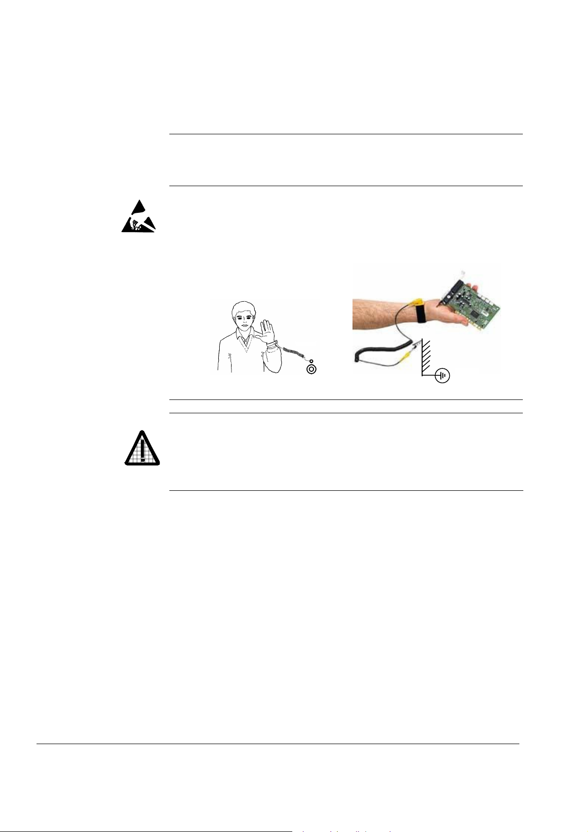
Printed circuit boards and fiber optic cables
These instructions are intended for all who handle the circuit boards
and fiber optic cables. Ignoring the following instructions can cause
damage to the equipment.
WARNING! The printed circuit boards contain components sensitive to
electrostatic discharge. Wear a grounding wrist band when handling
the boards. Do not touch the boards unnecessarily.
Use grounding strip:
ABB order no.: 3ADV050035P0001
WARNING! Handle the fiber optic cables with care. When unplugging
optic cables, always grab the connector, not the cable itself. Do not
touch the ends of the fibers with bare hands as the fiber is extremely
sensitive to dirt. The minimum allowed bend radius is 35 mm (1.38 in.).
Safety instructions
3ADW000195R0501 DCS800 Service Manual e e
Page 9

9
Mechanical installation
These notes are intended for all who install the drive. Handle the unit
carefully to avoid damage and injury.
• Make sure that dust from drilling does not enter the drive when
• Ensure sufficient cooling.
• Do not fasten the drive by riveting or welding.
WARNING!
• DCS800 sizes D4 ... D7: The drive is heavy. Do not lift it alone. Do
not lift the unit by the front cover. Place units D4 and D5 only on its
back.
DCS800 sizes D5 ... D7: The drive is heavy. Lift the drive by the
lifting lugs only. Do not tilt the unit. The unit will overturn from a tilt
of about 6 degrees.
installing. Electrically conductive dust inside the unit may cause
damage or lead to malfunction.
Safety instructions
3ADW000195R0501 DCS800 Service Manual e e
3ADW000195R0101 DCS800 Service Manual e a
Page 10

10
Operation
These warnings are intended for all who plan the operation of the drive
or operate the drive. Ignoring the instructions can cause physical injury
or death and/or damage to the equipment.
WARNING!
• Before adjusting the drive and putting it into service, make sure
that the motor and all driven equipment are suitable for operation
throughout the speed range provided by the drive. The drive can
be adjusted to operate the motor at speeds above and below the
base speed.
• Do not control the motor with the disconnecting device
(disconnecting mains); instead, use the control panel keys
and
, or commands via the I/O board of the drive.
• Mains connection
You can use a disconnect switch (with fuses) to disconnect the
electrical components of the drive from the mains for installation
and maintenance work. The type of disconnect switch used must
be as per EN 60947-3, Class B, so as to comply with EU
regulations, or a circuit-breaker type which switches off the load
circuit by means of an auxiliary contact causing the breaker's main
contacts to open. The mains disconnect must be locked in its
"OPEN" position during any installation and maintenance work.
• EMERGENCY STOP buttons must be installed at each control
desk and at all other control panels requiring an emergency stop
function. Pressing the STOP button on the control panel of the
drive will neither cause an emergency stop of the motor, nor will
the drive be disconnected from any dangerous potential.
To avoid unintentional operating states, or to shut the unit down in
case of any imminent danger according to the standards in the
safety instructions it is not sufficient to merely shut down the drive
via signals "RUN", "drive OFF" or "Emergency Stop" respectively
"control panel" or "PC tool".
• Intended use
The operating instructions cannot take into consideration every
possible case of configuration, operation or maintenance. Thus,
they mainly give such advice only, which is required by qualified
personnel for normal operation of the machines and devices in
industrial installations.
If in special cases the electrical machines and devices are intended for use in non-industrial installations - which may require
stricter safety regulations (e.g. protection against contact by
children or similar) - these additional safety measures for the
installation must be provided by the customer during assembly.
Safety instructions
3ADW000195R0501 DCS800 Service Manual e e
Page 11

11
Note:
• When the control location is not set to Local (L not shown in the
status row of the display), the stop key on the control panel will not
stop the drive. To stop the drive using the control panel, press the
LOC/REM key and then the stop key
.
Safety instructions
3ADW000195R0501 DCS800 Service Manual e e
3ADW000195R0101 DCS800 Service Manual e a
Page 12

12
Safety instructions
3ADW000195R0501 DCS800 Service Manual e e
Page 13

13
Table of contents
Safety instructions 5
What this chapter contains..........................................................................................................5
To which products this chapter applies.......................................................................................5
Usage of warnings and notes .....................................................................................................5
Installation and maintenance work..............................................................................................6
Grounding........................................................................................................................7
Mechanical installation................................................................................................................9
Operation ..................................................................................................................................10
Table of contents 13
Introduction 16
How to use this manual.............................................................................................................16
Contents of this manual ............................................................................................................16
Target group .............................................................................................................................16
Associated publications ............................................................................................................16
Storage and transport ...............................................................................................................17
Name plate and type code ........................................................................................................17
Type code .................................................................................................................................18
Current and voltage ratings.......................................................................................................19
Fault Tracing Thyristors 21
Tools .........................................................................................................................................21
For commissioning and fault tracing..............................................................................21
Additionally for service and preventive maintenance ....................................................22
How to detect a faulty thyristor..................................................................................................22
A fuse is blown ..............................................................................................................22
DC-current pulses measured by an oscilloscope ..........................................................23
Thyristor diagnosis ........................................................................................................23
Ripple monitor ...............................................................................................................23
How to find a faulty thyristor......................................................................................................24
Converters size D1 to D4 (20...1000 A).........................................................................24
Blown fuses ...................................................................................................................24
Converters size D5, D6, and D7 (900...5200 A) ............................................................25
Blown fuses ...................................................................................................................25
Ripple monitor ...............................................................................................................25
Handling the Semiconductors 27
General Instruction how to handle the Semiconductors ...........................................................27
Exchange of Thyristors for Size D1 to D4 29
Installation of OnBoard bridge and thyristor modules in converters size D1 to D4
(20...1000 A) .............................................................................................................................29
Required Tools ..............................................................................................................29
Find faulty thyristor modules .........................................................................................29
Remove faulty thyristor modules ...................................................................................30
Install new thyristor modules .........................................................................................34
Table of contents
3ADW000195R0501 DCS800 Service Manual e e
Page 14

14
Remove faulty OnBoard bridge (V1) ............................................................................ 36
Install new OnBoard bridge (V1) .................................................................................. 36
OnBoard bridge (V1) and thyristor module location in DCS800-S01 (2-Q) units.......... 37
OnBoard bridge (V1) and thyristor module location in DCS800-S02 (4-Q) units.......... 38
OnBoard bridge and thyristor module terminals ........................................................... 39
Exchange of Thyristors for Size D5 41
Installation of "Disc Type" thyristor in converters size D5 (900...2000 A) ................................ 41
Required Tools ............................................................................................................. 41
Disk type thyristors ....................................................................................................... 42
Find faulty thyristor ....................................................................................................... 45
Remove faulty thyristor................................................................................................. 46
Install new thyristor....................................................................................................... 47
Exchange of Thyristors for Size D6 51
Installation of "Disc Type" thyristor in converters size D6 (1900...3000 A) .............................. 51
Required Tools ............................................................................................................. 51
Disk type thyristors ....................................................................................................... 52
BCT thyristors............................................................................................................... 53
Find faulty thyristor ....................................................................................................... 54
Remove faulty thyristor................................................................................................. 55
Install new thyristor....................................................................................................... 58
Exchange of Thyristors for Size D7 65
Installation of "Disc Type" thyristor in converters size D7 (2050...5200 A) .............................. 65
Required Tools ............................................................................................................. 65
Find faulty thyristor ....................................................................................................... 66
Install new thyristor....................................................................................................... 69
Exchange of SDCS-CON-4 75
General .................................................................................................................................... 75
Required Tools ............................................................................................................. 75
Overview SDCS-CON-4 exchange............................................................................... 75
Service 83
How to remove the converter fans in frames D1 to D3 (two fans) ........................................... 83
How to remove the converter fans in a frame D3 (four fans) ................................................... 87
How to remove the converter fan in a frame D6 ...................................................................... 92
How to remove the converter fan in a frame D7 ...................................................................... 93
DCS800 firmware download .................................................................................................... 94
General......................................................................................................................... 94
Download SDCS-CON-4 firmware................................................................................ 94
Add firmware or text files ............................................................................................ 107
Create a workspace.................................................................................................... 114
Download SDCS-COM-8 firmware ............................................................................. 129
Set type code ......................................................................................................................... 131
Type code table .......................................................................................................... 133
DC-Motor neutral zone adjustment ........................................................................................ 134
Types concerned ........................................................................................................ 134
Summary .................................................................................................................... 134
General....................................................................................................................... 134
Table of contents
3ADW000195R0501 DCS800 Service Manual e e
Page 15

15
Preventive Maintenance 135
Recommended regular maintenance......................................................................................136
Maintenance schedule ............................................................................................................136
Annual preventive maintenance..............................................................................................137
3 years preventive maintenance .............................................................................................140
6 years preventive maintenance .............................................................................................141
9 years preventive maintenance .............................................................................................143
Appendix A - Spare Parts List 145
Table of contents
3ADW000195R0501 DCS800 Service Manual e e
Page 16

16
Introduction
How to use this manual
The purpose of this service manual is to provide detailed information on how to
service power converters from the DCS800 series.
Contents of this manual
Safety instructions
This chapter is located at the beginning of this manual.
Introduction
This chapter informs about the contents and the use of this manual as well as the
boundary conditions applying and the thyristor power converter rating plate.
Fault Tracing Thyristors
This chapter describes how to detect and select a faulty thyristor.
Handling the Semiconductors
This chapter describes the handling of thyristors and thyristor modules.
Exchange of Thyristors of Sizes D1 to D4
This chapter describes the exchange of thyristors in converters sizes D1 to D4.
Exchange of Thyristors of Size D5
This chapter describes the exchange of thyristors in converters size D5.
Exchange of Thyristors of Size D6
This chapter describes the exchange of thyristors in converters size D6.
Exchange of Thyristors of Size D7
This chapter describes the exchange of thyristors in converters size D7
Exchange of SDCS-CON-4
This chapter describes the exchange of a SDCS-CON-4
Service
This chapter contains hardware information and technical hints.
Preventive Maintenance
This chapter describes the measures for preventive maintenance of the thyristor
converters.
Appendix A Spare Parts list
The Appendix A contains the spare parts list of the converters.
Target group
This manual is designed to help those responsible for planning, installing, starting
up and servicing the thyristor power converter.
These people should possess:
basic knowledge of physics and electrical engineering, electrical wiring
principles, components and symbols used in electrical engineering, and
basic experience with DC drives and products.
Associated publications
A list of associated publications is published on the inner page of this manual’s
cover, see DCS800 Drive Manuals
The DCS800 Hardware Manual (3ADW000194) describes all hardware
Introduction
3ADW000195R0501 DCS800 Service Manual e e
. Here is a list of the most important ones:
Page 17
17
R
components of the DCS800, their connections and settings (e.g. jumpers)
The DCS800 Firmware Description (3ADW000193) gives an overview of the
DCS800 firmware, describes all parameters, describes the function of the DCS
Control Panel, gives support in case of faults and alarms and gives information
about communication.
The above listed documentation can be found on the CD-ROM being attached to
the DCS800 Quick Guide (3ADW000191).
Storage and transport
If the unit has been in storage prior to installation or is transported to another
location, care must be taken to ensure that the environmental conditions are
complied with (see Hardware Manual).
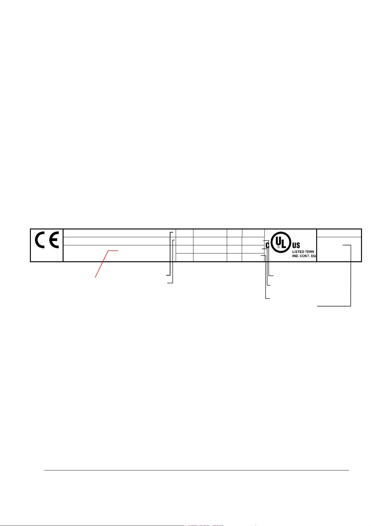
Name plate and type code
For purposes of identification, each thyristor power converter is fitted with name
plates, stating the type code and the serial number, which serve for each unit's
individual identification.
The type code contains information about the characteristics and the configuration
of the unit.
ABB Automation Products
Type: DCS800-S02-0025-05
Ser No: 0025421A06294264
Production year
2006 and week 29
Example of a name plate
Rated input voltage
Rated input current
U
1
I
1
f
1
SCC
3 525 V
20 A I
50/60 Hz If 6 A
65 kA
U2 610 V
25 A
2
Fan
----
Rated output current
Rated internal field
exciter current
Rated fan voltage
Plus code
Made in Germany
+K454
+J409
Introduction
3ADW000195R0501 DCS800 Service Manual e e
Page 18

18
Type code
The type code contains information on the specifications and configuration of the
drive. The first digits from left express the basic configuration (e.g. DCS800-S01-
2005). The optional selections are given thereafter, on the name plate by plus
code. The main selections are described below. Not all selections are available for
Position Plus code
Product series DCS800
A Type S0 = Standard converter module IP00
X Bridge type 1 = Single bridge (2-Q)
Y Rated DC current YYYY = Rated current (e.g. 0025 = 25 ADC)
ZZ Rated AC voltage 04 = 400 VAC
B Power connection - = Standard D1 ... D6
Internal field exciter
configuration
Fan voltage
Current measurement +S175 SDCS-CMA-2 for sizes D5 to D7
Voltage measurement +S186
SDCS-DSL-4 +S199
+ plug-in options
DCS Control Panel
Fieldbus
I/O and DDCS L500
all types.
Type code D C S 8 0 0 -AAX-YYYY-ZZ- plus code
Position A X Y Z B
R0 = Rebuild system
E0 = Panel solution
A0 = Enclosed converter
2 = 2 anti parallel bridges (4-Q)
05 = 525 VAC
06 = 600 VAC
07 = 690 VAC
08 = 800 VAC
10 = 990 VAC
12 = 1200 VAC
L = Left side D7
R = Right side D7
a = Second thyristor type D5, D6
+S164
+0S163
+S171
+S172
+S180
+S181
+S182
+S183
+S189
+0S199
0J400
J409
K454
K451
K466
K458
L501
L508
L509
With internal field exciter, external supply (only D5:25 A, Rebuild kit: 25 A/16 A)
Without internal field exciter (only D1 ... D4)
Size D4
Standard fan voltage: 230 V / 1-ph
Additional fan voltage: 115 V / 1-ph
Size D6
Standard fan voltage for 400 V / 500 V / 800 V units: 400-500 V / 3-ph
Standard fan voltage for 600 V / 690 V units: 525-690 V / 3-ph
Additional fan voltage for 600-690 V units: 400-500 V / 3-ph
120 V SDCS-SUB-4 for sizes D1 ... D4
600 V for sizes D6 and D7
690 V for sizes D6 and D7
800 V for sizes D6 and D7.
990 V for sizes D6 and D7.
Galvanic isolation for sizes D6 and D7
With SDCS-DSL-4
Without SDCS-DSL-4
Without DCS Control Panel
Door mounting Kit (cable length 3 m)
Profibus RPBA
DeviceNet RDNA
Ethernet IP + Modbus TCP RETA
Modbus RMBA
Analogue Extension RAIO
Digital Extension RDIO
DDCS Communication board (10 Mbaud CH0) SDCS-COM-81
DDCS Communication board (5 Mbaud CH0) SDCS-COM-82
Introduction
3ADW000195R0501 DCS800 Service Manual e e
Page 19

19
The technical data and specifications are valid as of going to press. ABB reserves
the right to make subsequent alterations.
If you have any questions concerning your drive system, please contact your local
ABB agent.
Current and voltage ratings
Unit size 2-Q rated current
DCS800-01 [ADC]
D1
D3
D4
D5
D6
D7
1
only available as 2-Q drive
20 25 X X
45 50 X X
65 75 X X
90 100 X X
125 140 X X
180 200 X X D2
230 260 X X
315 350 X X X
405 450 X X
470 520 X X
610 680 X X X
740 820 X X
900 1000 X X
900 900 X X
1200 1200 X X
1500 1500 X X X X
2000 2000 X X X
1900 1900 X
2050 2050 X X X
2500 2500 X X X X X
3000 3000 X X X X X
2050 2050 X
2600 2600 X X
3300 3300 X X X X X X X
4000 4000 X X X X X X X
4800 4800 X X X
5200 5200 X X
4-Q rated current
DCS800-02 [ADC]
400 525 600 690 800 990 1200
Supply voltage [VAC]
1
X1
Introduction
3ADW000195R0501 DCS800 Service Manual e e
Page 20

20
Introduction
3ADW000195R0501 DCS800 Service Manual e e
Page 21

21
Fault Tracing Thyristors
Tools
For commissioning and fault tracing
Following software tools are mandatory:
DriveWindow Light including commissioning wizard and DWL AP for Adaptive
Program and
DriveWindow for fast drive monitoring using SDCS-COM-8.
Following tools are mandatory in addition to standard tools:
An oscilloscope including memory function with either galvanically isolating
transformer or isolating amplifier (probe) for safe measurements. It can also be
a hand held (portable) oscilloscope.
A clamp on current probe. In case the scaling of the DC load current needs to
be checked it must be a DC clamp on current probe.
A voltmeter (at least CAT III 1000 V):
Make sure that all equipment in use is suitable for the voltage level applied to the
Fault Tracing Thyristors
1000 V probes and test leads:
An ESD-field service kit (ABB Service
Finland code 0001ESD / MS-Antistatic):
power part!
3ADW000195R0501 DCS800 Service Manual e e
3ADW000195R0501 DCS800 Service Manual e e
Page 22

22
Additionally for service and preventive maintenance
Following additional tools are mandatory for cleaning:
An ESD safe blower / ESD vacuum
cleaner (ABB Service Finland code
0006ESD / MUNTZ 555-ESD-S-E):
How to detect a faulty thyristor
Thyristor problems can be noticed differently:
A fuse is blown
This is an indication, that a strong overcurrent has happened due to one of the
following reasons:
An internal short circuit between the phases (line side) because of a defective
thyristor (short circuit inside a thyristor from anode to cathode).
An internal short circuit between the phases (line side) because of circulating
current in a 4-Q converter (malfunction of the control electronics, no thyristor
defective).
An external short circuit at the DC terminals of the converter without sufficient
impedance.
A commutation fault during generating (active braking with high current, high
EMF and with low AC voltage) of a 4-Q converter.
Note:
In case of parallel fuses: If one of the parallel fuses is blown, all parallel fuses have
to be changed. The ‘undamaged’ fuses might be ‘half-blown’ and will blow with the
next high current.
Fault Tracing Thyristors
3ADW000195R0501 DCS800 Service Manual e e
Page 23
23
DC-current pulses measured by an oscilloscope
Connect an oscilloscope to the fixed AO I-act (X4:9/10 on the SDCS-CON-4 or
X4:5/6 on the SDCS-IOB-3) and check for the proper amount of current pulses:
Six current pulses in positive direction
There should be six current pulses in positive direction.
In case of a 4-Q converter also the six current pulses for the negative direction
have to be checked.
Thyristor diagnosis
Also the thyristor diagnosis provided by the firmware can be used:
Switch the drive to local mode (DriveWindow, DriveWindow Light, DCS Control
Panel or local I/O).
Start the thyristor diagnosis by means of ServiceMode (99.06) = ThyDiagnosis
and set On and Run within 20 s.
During the thyristor diagnosis the main contactor will be closed and the
thyristors are checked. The field current is not released while the thyristor
diagnosis is active and thus the motor should not turn.
When the thyristor diagnosis is finished check Diagnosis (9.11) for details.
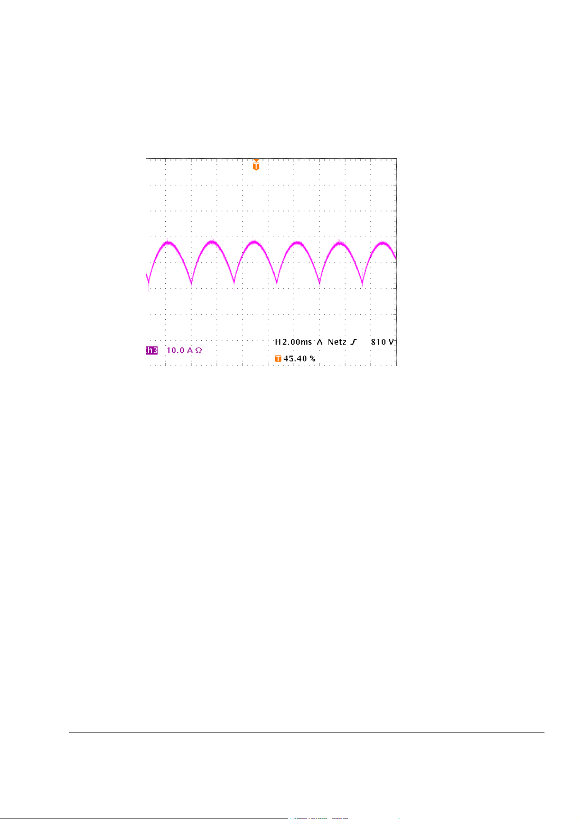
Ripple monitor
The ripple monitor indicates that the ripple of the DC current is much higher than
normal. In such a case, most often one thyristor does not work. It’s missing current
contribution causes a deep dip in the direct current.
The structure of the current loop (current controller) will force the other thyristors to
compensate the dip by a certain overcurrent in order to keep the average current
constant. Such a compensation results in a ripple monitoring fault during motoring
mode operation with 90°.
The reason for a current less thyristor may be:
Fault Tracing Thyristors
Page 24
24
A fuse has disconnected one of the six thyristors. This is possible only for
converters with 900 ... 5200 A (six internal branch fuses). A converter with
three external fuses stops working completely at once when one of the three
AC input fuses interrupts a phase input of the converter.
A thyristor does not get firing pulses or does not react to firing pulses.
The current controller may be totally mismatched to the DC load.
The AC mains network is causing that fault message. In this case,
asymmetrical phase shift, uneven phase voltage or critical designed power
factor correction equipment or harmonic reduction equipment can be the
reason.
How to find a faulty thyristor
If a blown fuse is suspected in the converter, the problem is caused most often by
a faulty thyristor. To make sure, that a thyristor is the reason and needs to be
exchanged fault tracing must be done in two different ways, depending on the size
of the converter.
In general, make sure, that all safety instructions, given within this manual or
within the safety instructions, related to the machine or the application itself,
are obeyed.
Converters size D1 to D4 (20...1000 A)
These converters require semiconductor fuses in the 3 AC lines.
The converter must be disconnected from the mains.
One motor armature cable should be disconnected from the converter.
Blown fuses
Using the OHM function of a normal multimeter, measurements must be made
from each AC terminal to each DC terminal (U1 to C1, V1 to C1, W1 to C1, U1
to D1, V1 to D1 and W1 to D1; see picture Anti-parallel B6-bridges with
branching fuses on page 45). Normally, every measurement should show high
resistance (> 1 k).
Target: find a short circuit, indicated by low resistance ( <1 ) (destroyed
thyristor).
If the converter is designed with half-bridge thyristor modules, then a module
consists of two anti-parallel thyristors. In this case it is sufficient to know which
thyristor pair or module has a defective thyristor because the complete module
must be replaced.
After a thyristor module is replaced, the above mentioned measurement should
be done another time to make sure that all faulty thyristors have been detected!
Note:
The RC circuit could also cause 0 result for a short time.
The measurement, showing less resistance than 1 should be made a second
time with test leads applied to the terminals with opposite polarity; if this
measurement shows the same result, one or two thyristors located in that path are
faulty; they need to be replaced.
Fault Tracing Thyristors
3ADW000195R0501 DCS800 Service Manual e e
Page 25

25
Converters size D5, D6, and D7 (900...5200 A)
These converters are equipped with fuses in the branches of the
power part.
The converter must be disconnected from the mains.
Blown fuses
In case of a blown fuse, the faulty thyristor or the faulty pair of
thyristors are already isolated at one side from the others and
therefore the faulty branch is known (see picture Anti-parallel
B6-bridges with branching fuses on page 45).
The OHM test should be performed, when the thyristor is still
clamped. Outside the converter a special thyristor clamping
device is needed.
For 4-Q converters with anti-parallel thyristors or BCT’s:
The selection of a forward or reverse thyristor or BCT
(Bidirectional-Controlled-Thyristor) is done during the
disassembly. Continue with related part Exchange of Thyristors
for Size D5
After a thyristor was replaced, the OHM test should be done
another time to make sure that all faulty thyristors have been
detected! If the motor is still connected to the converter the
result of the measurement may be wrong.
, D6 or D7 section Find faulty thyristor.
Ripple monitor
If the ripple monitor fault occurred, a fault tracing as described
above must be carried out:
Check the fuses and the thyristors, according to the statements
before.
If the power section seems to be ok, but still one or more
thyristors don’t take current, something went wrong in between
the firing pulse generation and the thyristor’s gate; in this case
check:
Is a firing pulse present on the primary side of the firing
pulse transformer?
Is a firing pulse present on the secondary side of the
firing pulse transformer?
Is the firing pulse transferred to the gate of the thyristor?
Are there all electrical connections still healthy?
Can the thyristor be fired with the applied firing pulse? Is
the pulse form of the firing pulse identical at all
measuring positions?
Check the settings of the current controller.
Check the AC mains network by taking recordings of the line
voltage and current at all 3 phases at the same time.
Fault Tracing Thyristors
Page 26

26
Fault Tracing Thyristors
3ADW000195R0501 DCS800 Service Manual e e
Page 27

27
Handling the Semiconductors
General Instruction how to handle the Semiconductors
Thyristor modules, busbars and fuses have to be mounted with the correct torque
using a torque screw driver or torque wrench.
In converters sizes D5 (900 ... 2000 A), D6 (1900 ... 3000 A) and D7 (2050 ... 5200
A) the mounting force is indicated by an indicating spring welded to the mounting
clamp, which is inside the unit.
Always mark suspected damaged components clearly after removing them from
the circuit, to avoid confusion with "good" components.
When removing a damaged semiconductor, write down how and where it was
installed (direction, location, connected gate leads and with BCT’s the position of
the gate connectors).
Check that the new and old components have the same type designation or that
the new component can replace the old one. A semiconductor can be replaced by
different compatible semiconductor according to the codes in the manufacturers'
table.
Semiconductor components are high-precision products. All unnecessary used
tools and objects might damage the easily dented and scratched surfaces of the
semiconductors.
1. Keep new semiconductors as long as possible in their original packages.
2. Use protective gloves if possible.
3. Clean work area and hands frequently.
4. Use good illumination.
Handling the Semiconductors
3ADW000195R0501 DCS800 Service Manual e e
Page 28

28
Handling the Semiconductors
3ADW000195R0501 DCS800 Service Manual e e
Page 29
29
Exchange of Thyristors for Size D1 to D4
Installation of OnBoard bridge and thyristor modules in converters size
D1 to D4
All DCS800 size D1 to D4 are equipped with an OnBoard bridge (excitation) and
(20...1000 A)
thyristor modules. In order to keep the operating temperature of the semiconductor
module low, the joint between the heat sink and the module should have a good
heat conducting ability. The electrical conductivity of the connectors must also be
good. For this reason the following instructions must be observed with particular
care.
Required Tools
Special tools or material needed in addition to standard tools for the exchange of
thyristor modules:
Torx screwdrivers: TX10, TX20, TX25
Torque spanner: mounting torques for the OnBoard bridge and the
thyristor modules to heat sink and electrical
connections see table Nominal mounting torque for
OnBoard bridge and thyristor modules on page 35
Screws are metric type; use appropriate nuts
Tissue paper
Solvent (e.g. ethanol)
Thermal joint compound:
(grease)
Manufacturer: Carl Bechem GmbH, 58089 Hagen
ABB Service: GHSN 390 011 P 0051
or
thermal joint compound: type WLPF 20 (10 ml)
ABB Service: GHSN 390 011 P 10
Before the work is started, disconnect the converter from the power supply
completely, then check the voltage free condition and make sure, everything
is located in an electrical and mechanical safe condition!
type Berulub FZ1 E3
Find faulty thyristor modules
See Fault Tracing Thyristors
of this publication.
Exchange of Thyristors for Size D1 to D4
3ADW000195R0501 DCS800 Service Manual e e
Page 30
30
Remove faulty thyristor modules
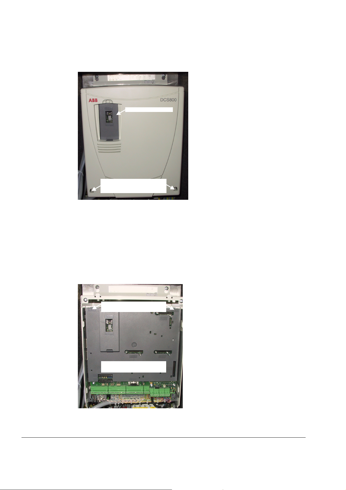
1. Remove the DCS Control Panel and design cover:
Remove DCS Control Panel
Depress the locks by means of a
screwdriver to remove the design
Remove design cover
2. Remove all plug in options on the intermediate cover e.g.:
serial communication modules (R-type),
extension I/O modules (RAIO, RDIO),
extension modules for second encoder (RTAC) or resolver (RRIA),
communication board (SDCS-COM-8),
isolated I/O (SDCS-IOB-2x, SDCS-IOB-3) and
SDCS-MEM-8 (Memory Card).
3. Remove the intermediate cover by depressing the two locks on the upper right
and left hand side of the cover:
cover
Depress the locks to remove the
design cover
Remove all o ptions, so that the
intermediate cover is empty
Remove plug in options
Exchange of Thyristors for Size D1 to D4
3ADW000195R0501 DCS800 Service Manual e e
Page 31

31
4. Disconnect all I/O plugs (X3 to X7) at the SDCS-CON-4 and the plugs at the
SDCS-DSL-4 board, if used (X51 to X54):
Disconnect all plugs from SDCS-
CON-4 and SDCS-DSL-4 boards
Disconnect all plugs
5. Remove the grounding plug and the holding screw at the electronic tray:
Remove the grounding plug and the
holding screw
Remove grounding and screws
Exchange of Thyristors for Size D1 to D4
3ADW000195R0501 DCS800 Service Manual e e
Page 32

32
6. To unhinge the electronic tray including the SDCS-CON-4 pull it up and then
out. Before remove tray completely unplug the flat cables (X12, X13, X37):
Electronic tray with SDCS-CON-4
Remove flat cables
Unhinge electronic tray
7. Remove all cables and plugs at the SDCS-PIN-4:
Keep winding direction and
amount of windings for T100
in mind.
How to handle X8:
use screw dr iver
X8
T100
Remove all cables
and plugs
Remove cables at the SDCS-PIN-4
Attention:
Write down the winding direction of the cable through T100!
D1: thread the wire 4 times through the hole in T100 (that equals 3 loops)
D2 - D4: thread the wire 1 time through the hole in T100 (that equals no loops)
Exchange of Thyristors for Size D1 to D4
3ADW000195R0501 DCS800 Service Manual e e
Page 33

33
8. Remove the SDCS-PIN-4 board:
OnBoard field exciter
bridge module
Thyristor modules
Snubber resistor
Current transformer Temperature sensor
Remove SDCS-PIN-4
9. Remove the gate leads from the faulty thyristor module and mark the
connectors clearly.
10. Remove the busbars necessary to get full access to the faulty thyristor module.
11. If a current transformer must be removed, mark its position and the
connections clearly.
Note:
Remove only as many parts as needed around the faulty thyristor module.
12. Remove the faulty thyristor module and mark it clearly as defective.
Exchange of Thyristors for Size D1 to D4
3ADW000195R0501 DCS800 Service Manual e e
Page 34

34
Install new thyristor modules
1. Ensure that the new thyristor module is of the correct type (see appendix A of
this manual).
2. Remove old heat conducting compound (grease) from the heat sink. Clean the
mounting surfaces (heat sink and thyristor module) with an appropriate solvent
(e.g. ethanol) by means of tissue paper. When the heat sink is clean, spread
out the heat conducting compound with a rubber spatula or by hand.
3. Apply a thin layer of heat conducting compound to the new thyristor module:
Application of heat conducting compound
4. Spread the heat conducting compound evenly by moving the thyristor module
forward and backward on the heat sink.
5. Tighten all clamping screws by hand until the screw heads touch the bottom of
the thyristor module. Then tighten the screws to 2.0 Nm torque.
Note:
If the thyristor module is mounted by means of four screws, tighten the screws
crosswise.
6. Tighten the screws to nominal torque according to table Nominal mounting
torque for OnBoard bridge and thyristor modules page 35.
Exchange of Thyristors for Size D1 to D4
3ADW000195R0501 DCS800 Service Manual e e
Page 35

35
OnBoard bridge and thyristor modules
Size Type Electrical
29 mm bridge block VVZF 70-16 - 5 Nm
20 mm block SKKT 27, 42, 57, 106 3 Nm 5 Nm
20 mm block MCC 26, 44, 56, 95 2.5 ... 4 Nm 2.5 ... 4 Nm
34 mm block MCC 162 4.45 … 5.5 Nm 2.25 … 2.75 Nm
34 mm block SKKT 162 5 Nm 5 Nm
34 mm block TT 162 6 Nm 6 Nm
50 mm block MCC 255 11 … 13 Nm 4.5 … 7 Nm
50 mm block TT 250, 330 12 Nm 6 Nm
60 mm block TT 425, 570 12 Nm 6 Nm
Nominal mounting torque
Thyristor module
connections
to heat sink
Nominal mounting torque for OnBoard bridge and thyristor modules
7. Reinstall the current transformer, make sure, its position is correct.
8. Reinstall the busbars, make sure, the correct torque is applied according to
table Nominal mounting torque for OnBoard bridge and thyristor modules
on
page 35.
9. Reconnect all gate leads to the thyristor module.
10. Reinstall the SDCS-PIN-4 board.
11. Reconnect all cables and plugs at the SDCS-PIN-4:
snubber resistor (X30, X31),
temperature sensor (X22),
current transformers (X3, X4, X5),
OnBoard excitation (X8, X9, X11), use proper winding direction and amount
of windings for T100
gate leads (first X16, X18 then X15, X17),
OnBoard excitation line voltage (X1, X2, X7),
all plugs (X10, X96, X99) and
all flat cables (X12, X13, X37), use the lock connectors at the SDCS-PIN-4
12. Reconnect the flat cables at the SDCS-CON-4 (X12, X13, X37) and re-hinge
the electronic tray.
13. Reconnect the grounding plug and the holding screw at the electronic tray.
14. Reconnect all I/O plugs at the SDCS-CON-4 (X3 to X7) and the plugs at the
SDCS-DSL-4 (X51 to X54).
15. Reinstall the intermediate cover, all plug in options and the design cover.
Exchange of Thyristors for Size D1 to D4
3ADW000195R0501 DCS800 Service Manual e e
Page 36

36
Remove faulty OnBoard bridge (V1)
1. Follow the instructions Remove faulty thyristor modules until step 8 is done.
2. Remove all connectors from the faulty OnBoard bridge and mark the
connectors clearly.
3. Remove the faulty OnBoard bridge and mark it clearly as defective.
Install new OnBoard bridge (V1)
1. Ensure that the new OnBoard bridge is of the correct type (see appendix A of
this manual).
2. Remove old heat conducting compound (grease) from the heat sink. Clean the
mounting surfaces (heat sink and OnBoard bridge) with an appropriate solvent
(e.g. ethanol) by means of tissue paper. When the heat sink is clean, spread
out the heat conducting compound with a rubber spatula or by hand.
3. Apply a thin layer of heat conducting compound to the new OnBoard bridge.
4. Spread the heat conducting compound evenly by moving the OnBoard bridge
forward and backward on the heat sink.
5. Tighten all clamping screws by hand until the screw heads touch the bottom of
the thyristor module. Then tighten the screws to 2.0 Nm torque.
6. Tighten the screws to nominal torque according to table Nominal mounting
torque for OnBoard bridge and thyristor modules on page 35.
7. Reconnect all connectors to the OnBoard bridge.
8. Follow the instructions Install new thyristor modules
beginning with step 10.
Exchange of Thyristors for Size D1 to D4
3ADW000195R0501 DCS800 Service Manual e e
Page 37

37
OnBoard bridge (V1) and thyristor module location in DCS800-S01 (2-Q) units
V1 V1
DCS800-S01-0020 ... 0180
DCS800-S01-0230
V14/V11
1234 12
V14/V11
G1K1K2
G2
K
AK A
V16/V13
34
V1 V1
V16/V13 V12/V15
G2
KAK A
V12/V15
1234
G1K1K2
G1K1K2
G2
KAK A
V14/V11
K2 G2
K1 G1
V14/V11
A
K
AK
V16/V13 V12/V15
K2G2
K1G1
K2G2
DCS800-S01-0610 ... 0900DCS800-S01-0315 ... 0470
V16/V13 V12/V15
A K
AK
K1G1
A K AK
DCS800 loc of mod 1Q.dsf
Location of the OnBoard bridge and thyristor modules in DCS800-S01 (2-Q) units
Note:
This drawing is only showing the location of the OnBoard bridge and thyristor
modules, the actual converter module size is different!
Exchange of Thyristors for Size D1 to D4
3ADW000195R0501 DCS800 Service Manual e e
Page 38

38
OnBoard bridge (V1) and thyristor module location in DCS800-S02 (4-Q) units
DCS800-S02-0025 ... 0200
V1 V1
V14/V21 V16/V23
1234 1234 123
V12/V25
4
DCS800-S02-0260
V14/V21
K2G2
K1G1
V16/V23 V12/V25
K2G 2
K1G 1
K2G 2
K1G 1
1234 1234 1234
V11/V24
V13/V26 V15/V22
K1G1
V11/V24
K2G 2
K2G2
K1G 1
V13/V26
K1G 1
V15/V22
K2G 2
DCS800-S01-0680 ... 1000DCS800-S02-0350 ... 0520
V26/V13 V22/V15
A K AK
AK
A K
V23/V16
DCS800 loc of mod 4Q.dsf
A K AK
AK
A K
V25/V12
V11
V24
V15
V22
V13
V26
V1
K1
G1
G2
K2
K1
G1
G2
K2
K1
G1
G2
K2
KAK A
AK
K
A
KAK A
KAK A
K
AK
KAK A
K2
G2
V14
G1
K1
V21
K2
V12
G2
A
G1
K1
V25
K2
V16
G2
G1
K1
V23
V1
V24/V11
A
K
AK
A K AK
V21/V14
Location of the OnBoard bridge and thyristor modules in DCS800-S02 (4-Q) units
Note:
This drawing is only showing the location of the OnBoard bridge and thyristor
modules, the actual converter module size is different!
Exchange of Thyristors for Size D1 to D4
3ADW000195R0501 DCS800 Service Manual e e
Page 39

39
)
)
OnBoard bridge and thyristor module terminals
The next figures show the terminals of the OnBoard bridge and all used thyristor
modules. The terminal description is also stamped or marked by a sticker on the
OnBoard bridge and all thyristor modules.
For all firing pulse cables is valid:
Yellow is gate lead.
Red is cathode lead.
VVZF 70-16
(K)
(AK)
1
2
4
5
1
7
2 3
MCC26, 44, 56, 95
6
7 G
6 K
5 K
4 G
(A
3
(AK)
1
2
5
4
2
1
7
6
3
(K)
SKKT 27, 42, 57, 106
6 G
7 K
4 K
5 G
(A
3
(A)
3
3
6 7
67
(AK)
1
(K)
2
5
4
1
6
7
2
4 5
MCC162
54
SKTT 162
Exchange of Thyristors for Size D1 to D4
3ADW000195R0501 DCS800 Service Manual e e
Page 40

40
A
A
A
A
A
A
K
K
K1
G1
K2 G2
K
K
TT 162
K2 G2
K1 G1
MCC255
(A)
K
K
K1
G1
AK A
K2
K
TT 250, 330
G2
K2
G2
G1
K1
3
6G
7K
3
TT 425, 570
(K)
4K5G
2
Terminals of the OnBoard bridge and all thyristor modules
2
(AK)
1
1
4K
5G
6G
7K
Exchange of Thyristors for Size D1 to D4
3ADW000195R0501 DCS800 Service Manual e e
Page 41

41
Exchange of Thyristors for Size D5
Installation of "Disc Type" thyristor in converters size D5 (900...2000 A)
All DCS800 converters sizes D5/D6/D7 are equipped with disk type thyristors. The
structure of the "Disc type" semiconductor component is such that it requires a
certain compression force to operate. The prevention of overheating of the
component essentially depends on a good heat dissipation between the
semiconductor and the conducted heat sink. It is thus important that all joints have
good thermal and electrical conduction.
Required Tools
Special tools or material needed in addition to standard tools for the exchange of
thyristor modules:
Torx screwdrivers: TX10, TX20, TX25
Torque spanner for electrical connections: 13 Nm (M8)
25 Nm (M10)
50 Nm (M12)
Screws are metric type; use appropriate nuts.
17 mm ring spanner for fuse and busbar connections.
17 mm ring spanner for press clamp.
Tissue paper / solvent (e.g. ethanol).
Thermal joint compound: type BECHEM-RHUS SU 2
(grease)
Manufacturer: Carl Bechem GmbH, 58089 Hagen
ABB Service: GHSN 390 001 P 0001
Disassembly tool 3ADT 621 023 P1
Note:
For more detailed information about the wiring of the power part, see Hardware
Manual.
Therefore strict observance of the build in instructions given below is of utmost
importance. Make sure that the new component can replace the old one in
accordance with the spare part list (see Appendix A
Semiconductors and heat sinks are to be handled carefully to avoid scratches and
other damage. Avoid touching the contact surfaces. Do not lift the semiconductor
with the gate wire. Do not lift the semiconductor by touching the current contact
surfaces. Do not damage the welding flange or the contact surface.
Before you start work, disconnect the converter completely from the power
supply then check the voltage free condition and make sure, everything is
located in an electrically and mechanically safe condition!
).
Exchange of Thyristors for Size D5
3ADW000195R0501 DCS800 Service Manual e e
Page 42

42
Disk type thyristors
Some converter modules size D5 are equipped with different disc type thyristors.
For easy identification the name plate of the converter module is marked with “a”
after the voltage identification:
Converter with original
thyristor type T459Nxxx
Id code: DCA0012007P0001
DCS800-S01-0900-06 3 ~ 600 VAC
DCS800-S02-0900-06 3 ~ 600 VAC
DCS800-S01-0900-07 3 ~ 690 VAC
DCS800-S02-0900-07 3 ~ 690 VAC
Converter with original
thyristor type T589Nxxx
Id code: DCA0012015P0001
DCS800-S01-1200-04 3 ~ 400 VAC
DCS800-S02-1200-04 3 ~ 400 VAC
DCS800-S01-1200-05 3 ~ 525 VAC
DCS800-S02-1200-05 3 ~ 525 VAC
Parts list
The current and voltage ratings of original and second thyristor type are the same,
but the sizes of gate and cathode terminals are different. Thus it is not possible to
interchange both thyristor types as spares.
Attention: Use always the correct spare thyristor!
Original thyristor type (900 A)
Converter with original thyristor type T459Nxxx Id code: DCA0012007P0001
U
Converter with second
1
thyristor type T460Nxxx
Id code: 3ADC340105P0001
DCS800-S01-0900-06a
DCS800-S02-0900-06a
DCS800-S01-0900-07a
DCS800-S02-0900-07a
U
Converter with second
1
thyristor type T590Nxxx
Id code: 3ADC340106P0001
DCS800-S01-1200-04a
DCS800-S02-1200-04a
DCS800-S01-1200-05a
DCS800-S02-1200-05a
Original thyristor type
Exchange of Thyristors for Size D5
3ADW000195R0501 DCS800 Service Manual e e
Page 43

43
Gate (G): Faston 2.8 x 0.8 mm
Cathode (HK): Faston 4.8 x 0.8 mm
Conductive plate: Diameter 36 mm
Second thyristor type (900 A)
Converter with second thyristor type T460Nxxx Id code: 3ADC340105P0001
Second thyristor type
Gate (4): Round terminal D = 1.5 mm
Cathode (5): Faston 4.8 x 0.5 mm
Conductive plate: Diameter 36 mm
Original thyristor type (1200 A)
Converter with original thyristor type T589Nxxx Id code: DCA0012015P0001
Original thyristor type
3ADW000195R0501 DCS800 Service Manual e e
Exchange of Thyristors for Size D5
Page 44

44
Gate (G): Faston 2.8 x 0.8 mm
Cathode (HK): Faston 4.8 x 0.8 mm
Conductive plate: Diameter 36 mm
Second thyristor type (1200 A)
Converter with second thyristor type T590Nxxx Id code: 3ADC340106P0001
Second thyristor type
Gate (4): Round terminal D = 1.5 mm
Cathode (5): Faston 4.8 x 0.5 mm
Conductive plate: Diameter 36 mm
Exchange of Thyristors for Size D5
3ADW000195R0501 DCS800 Service Manual e e
Page 45

45
Find faulty thyristor
1. Find the defective branches by performing an OHM test (both polarities)
between U1, V1, W1 and C1, D1 (see fig. Anti-parallel B6-bridges with
branching fuses on page 45)
C1 (+)
V11 V13 V15V24 V26 V22
F11 F13 F15
U1
V1
W1
F14 F16 F12
V14 V16 V12V21 V23 V25
branching fuse
D1 (-)
princi ple_B6_a .dsf
Anti-parallel B6-bridges with branching fuses
2. Disconnect the branching fuses of the defective branches.
3. Find the defective thyristors by performing an OHM test (both polarities) over
their heat sinks.
4. In a 4-quadrant converter change both thyristors clamped between the same
heatsinks at once.
Note:
Because “Disc Type” semiconductors need a certain compression force to operate
properly, a measurement outside the clamped heat sinks might be wrong. To be
sure which thyristor is broken change only one thyristor, clamp the heat sinks
again and repeat step three.
branch
Exchange of Thyristors for Size D5
3ADW000195R0501 DCS800 Service Manual e e
Page 46

46
Remove faulty thyristor
1. Remove the screws of the DC – busbars and branch fuses preventing the
stack to be prized open.
Note:
It depends on the location of the defective thyristor which DC – busbar and
fuses have to be disconnected.
2. Write down the direction and location of the thyristors to be removed and mark
their gate leads.
3. Remove the gate leads if possible.
4. Loosen the mounting clamp (see fig. Aluminum spring with welded indicating
spring on page 47) at the top of the thyristor stack.
Attention: While loosen the mounting clamp the indicating spring must be pulled
out a little, otherwise the spring will be damaged!
5. Attach the disassembly tool at the faulty thyristor and prize open the upper and
lower heat sinks (see fig. How to use the disassembly tool
page 46).
6. Remove the thyristors.
Attention: To centre the thyristors spring pins are used. The pins are inlayed into
all lower heat sinks. Open the gap wide enough that the thyristor and the pins are
not damaged while removing the thyristor!
Mounting clamp
View from
the left
Disassembly tool
mountc l_b.dsf
Front view
View from
the right
How to use the disassembly tool
Exchange of Thyristors for Size D5
3ADW000195R0501 DCS800 Service Manual e e
Page 47

47
Install new thyristor
1. Ensure that the new thyristor is of the correct type (see Appendix A). Keep the
semiconductor and its surroundings clean. If necessary clean them with a
piece of tissue paper moistened with solvent.
Note:
Do not touch the polished surfaces of the thyristor.
2. Clean the polished surfaces of the semiconductor with a piece of tissue paper
moistened with solvent. Dry all surfaces. Spread a thin layer of heat
conducting paste on both sides of the thyristor, if necessary use a rubber
spatula.
3. Connect the gate leads if possible.
4. Clean all parts with tissue paper moistened with solvent, which have had or will
have contact with the thyristor or each other (lower / upper heat sink). Do not
clean the surfaces of grease too thoroughly, because the aluminum surfaces
will oxidize in a few seconds. Dry all surfaces.
5. Centre the thyristors by means of the spring pins.
Note:
Be sure that the thyristor is installed in the right direction. Do not pinch or cut
the gate leads or any other cable.
6. Turn the thyristor so that the gate leads point in the right direction.
Loose
condition
TORQUE INDICATING SPRING
Insulating plate
In- sulating tube
Correct torque
Heatsink
Aluminum spring with welded indicating spring
Exchange of Thyristors for Size D5
3ADW000195R0501 DCS800 Service Manual e e
Page 48

48
7. Tighten the nuts of the mounting clamp by hand so that the clamp is in parallel
with the contact surface of the heat sinks.
Note:
The indicating spring is a very sensitive instrument and must be handled with
care.
8. Tighten each nut in turn, half a turn at a time with the help of a ring spanner
until the indicating spring clicks into position “correct torque” (see fig. Aluminum
spring with welded indicating spring
on page 47). Do not tighten the screws any
further.
Note:
The correct torque is indicated by means of the welded indicating spring.
9. Perform an OHM test to make sure the thyristor is ok.
10. Reconnect the DC – busbars, branch fuses and all other dismantled parts.
11. Perform an OHM test between U1, V1, W1 and C1, D1 to make sure the power
part is ok.
U1 V1 W1
left stack
rear front
V24 V11
V13 V26
V22 V15
View from the left Front view View from the right
Location of thyristors in frame D5 (4-Q bridge)
right stack
front rear
V14 V21
V23 V16
V12 V25
Exchange of Thyristors for Size D5
3ADW000195R0501 DCS800 Service Manual e e
Page 49

49
U1 V1 W1
left stack
rear front
V11
V13
V15
View from the left Front view View from the right
right stack
front rear
V14
V16
V12
Location of thyristors in frame D5 (2-Q bridge)
Exchange of Thyristors for Size D5
3ADW000195R0501 DCS800 Service Manual e e
Page 50

50
W1
V1
U1
D1 (-)
C1 (+)
Exchange of Thyristors for Size D5
Location of branch fuses frame D5
3ADW000195R0501 DCS800 Service Manual e e
Page 51

51
Exchange of Thyristors for Size D6
Installation of "Disc Type" thyristor in converters size D6 (1900...3000 A)
All DCS800 converters sizes D5/D6/D7 are equipped with disk type thyristors. The
structure of the "Disc type" semiconductor component is such that it requires a
certain compression force to operate. The prevention of overheating of the
component essentially depends on a good heat dissipation between the
semiconductor and the conducted heat sink. It is thus important that all joints have
good thermal and electrical conduction.
Required Tools
Special tools or material needed in addition to standard tools for the exchange of
thyristor modules:
Torx screwdrivers: TX10, TX20, TX25
Torque spanner for electrical connections: 13 Nm (M8)
25 Nm (M10)
50 Nm (M12)
Screws are metric type; use appropriate nuts.
17 mm ring spanner for fuse and busbar connections.
24 mm ring spanner for press clamp.
Tissue paper / solvent (e.g. ethanol).
Thermal joint compound: type BECHEM-RHUS SU 2
(grease)
Manufacturer: Carl Bechem GmbH, 58089 Hagen
ABB Service: GHSN 390 001 P 0001
Disassembly tool DCF 1066721 P1
Note:
For more detailed information about the wiring of the power part, see Hardware
Manual.
Therefore strict observance of the build in instructions given below is of utmost
importance. Make sure that the new component can replace the old one in
accordance with the spare part list (see Appendix A)
Semiconductors and heat sinks are to be handled carefully to avoid scratches and
other damage. Avoid touching the contact surfaces. Do not lift the semiconductor
with the gate wire. Do not lift the semiconductor by touching the current contact
surfaces. Do not damage the welding flange or the contact surface.
Before you start work, disconnect the converter completely from the power
supply then check the voltage free condition and make sure, everything is
located in an electrically and mechanically safe condition!
.
Exchange of Thyristors for Size D6
3ADW000195R0501 DCS800 Service Manual e e
Page 52

52
Disk type thyristors
Some converter modules size D6 are equipped with different disc type thyristors.
For easy identification the name plate of the converter module is marked with “a”
after the voltage identification:
Converter with original
thyristor type T 1329Nxxx
Id code: 3ADC340081P0001
DCS800-S01-1900-08 3 ~ 800 VAC
DCS800-S02-1900-08 3 ~ 800 VAC
DCS800-S01-2050-05 3 ~ 525 VAC
DCS800-S02-2050-05 3 ~ 525 VAC
DCS800-S01-2050-06 3 ~ 600 VAC
DCS800-S02-2050-06 3 ~ 600 VAC
DCS800-S01-2050-07 3 ~ 690 VAC
DCS800-S02-2050-07 3 ~ 690 VAC
Parts list
The current and voltage ratings of original and second thyristor type are the same,
but the sizes of gate and cathode terminals are different. Thus it is not possible to
interchange both thyristor types as spares.
Attention: Use always the correct spare thyristor!
Original thyristor type
Thyristor T 1329Nxxx with Id code 3ADC340081P0001
U
Converter with second
1
thyristor type T 1xxx-24
Id code: 3ADC340098P0001
DCS800-S01-1900-08a
DCS800-S02-1900-08a
DCS800-S01-2050-05a
DCS800-S02-2050-05a
DCS800-S01-2050-06a
DCS800-S02-2050-06a
DCS800-S01-2050-07a
DCS800-S02-2050-07a
Original thyristor type
Exchange of Thyristors for Size D6
3ADW000195R0501 DCS800 Service Manual e e
Page 53

53
Gate (4): Faston 2.8 x 0.8 mm
Cathode (5): Faston 4.8 x 0.8 mm
Conductive plate: Diameter 48 mm
Second thyristor type
Thyristor T 1xxx-24 with Id code 3ADC340098P0001
Second thyristor type
Gate (y): Round terminal D = 1.5 mm
Cathode (K
): Faston 4.8 x 0.5 mm
1
Conductive plate: Diameter 50 mm
BCT thyristors
Gates of BCT
In some converter modules size D6 so called BCT’s (Bidirectional-ControlledThyristors) are used. BCT’s are a pair of anti-parallel thyristors in one disk type
housing. They can easily identified by the second pair of gate leads. The second
gate is marked with Gate B on the thyristor.
Faston 4.8 x 0.5
Gate A
Faston 6.3 x 0.8
Gate B
Gate B
BCT.ds f
Gate A
Exchange of Thyristors for Size D6
3ADW000195R0501 DCS800 Service Manual e e
Page 54

54
Note:
The Faston connectors of the gates are of different size.
Gate A should always be in front of the clamped heat sinks due to cooling reasons.
Location of BCT’s gate A when built in
Find faulty thyristor
1. Find the defective branches by performing an OHM test (both polarities)
between U1, V1, W1 and C1, D1 (see picture Anti-parallel B6-bridges with
branching fuses on page 45).
2. Disconnect the branching fuses of the defective branches.
3. Find the defective thyristors by performing an OHM test (both polarities) over
their heat sinks.
4. In a 4 - quadrant converter with BCT’s change the BCT.
5. In a 4 - quadrant converter with 2 single thyristors change both thyristors
clamped between the same heatsinks at once.
Note:
Because “Disc Type” semiconductors need a certain compression force to operate
properly, a measurement outside the clamped heat sinks might be wrong. To be
sure which thyristor is broken change only one thyristor, clamp the heat sinks
again and repeat step three.
Exchange of Thyristors for Size D6
3ADW000195R0501 DCS800 Service Manual e e
Page 55

55
Remove faulty thyristor
1. Replace all blown fuses and reconnect all fuses taken out during search for the
faulty thyristor.
2. Remove the screws of the DC - busbar plates adjacent to the defective
thyristors
DCbusbar
plates
Location of the DC - busbar plates
Note:
It depends on the location of the defective thyristor which DC-busbar plates have
to be disconnected.
Exchange of Thyristors for Size D6
3ADW000195R0501 DCS800 Service Manual e e
Page 56

56
g
3. Write down the direction and location of the thyristors to be removed and mark
their gate leads. In case of BCT’s add the position of the gates.
4. Remove the gate leads if possible.
5. Loosen the mounting clamp at the top of the thyristor stack.
mounting clamp indicating sprin
Handling of indicating spring and mounting clamp
Attention: While loosen the mounting clamp the indicating spring must be pulled
out a little, otherwise the spring will be damaged!
Do not remove the nuts totally, otherwise the treaded rods will fall down!
6. Pull out both DC-busbar plates.
DCbusbar
plates
DC-busbar plates
Exchange of Thyristors for Size D6
3ADW000195R0501 DCS800 Service Manual e e
Page 57

57
7. Attach the disassembly tool at the faulty thyristor and prize open the upper and
lower heat sinks.
push
down
push
down
Use of disassembly tool
8. Remove the thyristors with e.g. a pair of pliers.
Attention: To centre the thyristors spring pins are used. The pins are inlayed into
all lower heat sinks. Open the gap wide enough that the thyristor and the pins are
not damaged while removing the thyristor!
Exchange of Thyristors for Size D6
3ADW000195R0501 DCS800 Service Manual e e
Page 58

58
Install new thyristor
1. Ensure that the new thyristor is of the correct type (see appendix A). Keep the
semiconductor and its surroundings clean. If necessary clean them with a
piece of tissue paper moistened with solvent.
Note:
Do not touch the polished surfaces of the thyristor.
2. Clean the polished surfaces of the semiconductor with a piece of tissue paper
moistened with solvent. Dry all surfaces. Spread a thin layer of heat
conducting paste on both sides of the thyristor, if necessary use a rubber
spatula.
Prepare disk type thyristor
3. Clean all parts with tissue paper moistened with solvent, which have had or will
have contact with the thyristor or each other (lower / upper heat sink). Do not
clean the surfaces of grease too thoroughly, because the aluminum surfaces
will oxidize in a few seconds. Dry all surfaces.
4. Centre the thyristors by means of the spring pins.
Note:
Be sure that the thyristor is installed in the right direction. Do not pinch or cut
the gate leads or any other cable.
5. Turn the thyristor so that the gate leads point in the right direction. When
changing BCT’s make sure, that gate A is in front (see fig. Gates of BCT
on
page 53).
6. Connect the gate leads if possible.
7. Insert first the top DC-busbar plate and then the bottom one.
Exchange of Thyristors for Size D6
3ADW000195R0501 DCS800 Service Manual e e
Page 59

59
DC-busbar
plates and
heatsinks
DC-busbar plates and adjacent heat sinks
Note:
The DC - busbar plates should line up with the adjacent heat sinks.
8. Reconnect the DC-busbars.
9. Tighten the nuts of the mounting clamp by hand so that the clamp is in parallel
with the contact surface of the heat sinks.
Torque indicating
spring
loose condition
Mounting clamp; loose condition
Note:
The indicating spring is a very sensitive instrument and must be handled with
care.
10. Tighten each nut in turn, half a turn at a time with the help of a ring spanner
until the indicating spring clicks into position “correct torque”. Do not tighten the
screws any further.
Exchange of Thyristors for Size D6
3ADW000195R0501 DCS800 Service Manual e e
Page 60

60
Torque indicating
spring
correct torque
Mounting clamp, correct torque
Note:
The correct torque is indicated by means of the welded indicating spring.
11. Perform an OHM test to make sure the thyristor is ok.
12. Reconnect all other dismantled parts.
13. Perform an OHM test between U1, V1, W1 and C1, D1 to make sure the power
part is ok.
Exchange of Thyristors for Size D6
3ADW000195R0501 DCS800 Service Manual e e
Page 61

61
Stack
front rear
C1(+)
U1
D1(-)
V1
C1(+)
W1
V11
V21
V16
V26
V15
V24
V14
V23
V13
V22
V25
V12
D1(-)
View from the right
A6_thy r_loca t.dsf
Location of thyristors in frame D6 (4-Q bridge with single thyristors)
Exchange of Thyristors for Size D6
3ADW000195R0501 DCS800 Service Manual e e
Page 62

62
Gate A
Gate B
stack
front rear
C1(+)
V11 / V24
U1
V14 / V21
D1(-)
V1
C1(+)
W1
D1(-)
V16 / V23
V13 / V26
V15 / V22
V12 / V25
View from the right
A6_thyr_lo cat.dsf
Location of thyristors in frame D6 (4-Q bridge with BCT’s)
Exchange of Thyristors for Size D6
3ADW000195R0501 DCS800 Service Manual e e
Page 63

63
stack
front rear
C1(+)
V11
U1
V14
D1(-)
V1
C1(+)
W1
D1(-)
V16
V13
V15
V12
View from the right
A6_thyr_lo cat.dsf
Location of thyristors in frame D6 (2-Q bridge with single thyristors)
Exchange of Thyristors for Size D6
3ADW000195R0501 DCS800 Service Manual e e
Page 64

64
C1(+)
D1(-)
U1
V1
W1
F11
F14
F16
F13
F15
F12
C1(+)
F11
U1
F14
D1(-)
F16
V1
F13
C1(+)
F15
W1
F12
D1(-)
A6_branc h_fuse_l ocat.dsf
Location of parallel branch fuses frame D6
Exchange of Thyristors for Size D6
3ADW000195R0501 DCS800 Service Manual e e
Page 65

65
Exchange of Thyristors for Size D7
Installation of "Disc Type" thyristor in converters size D7 (2050...5200 A)
All DCS800 converters sizes D5/D6/D7 are equipped with disk type thyristors. The
structure of the "Disc type" semiconductor component is such that it requires a
certain compression force to operate. The prevention of overheating of the
component essentially depends on a good heat dissipation between the
semiconductor and the conducted heat sink. It is thus important that all joints have
good thermal and electrical conduction.
Required Tools
Special tools or material needed in addition to standard tools for the exchange of
thyristor modules:
Torx screwdrivers: TX10, TX20, TX25
Torque spanner for electrical connections: 13 Nm (M8)
25 Nm (M10)
50 Nm (M12)
Screws are metric type; use appropriate nuts.
17 mm ring spanner for fuse and busbar connections.
24 mm ring spanner for press clamp.
Tissue paper / solvent (e.g. ethanol).
Thermal joint compound: type BECHEM-RHUS SU 2
(grease)
Manufacturer: Carl Bechem GmbH, 58089 Hagen
ABB Service: GHSN 390 001 P 0001
Disassembly tool: DCF 1066721 P1
Note:
For more detailed information about the wiring of the power part, see Hardware
Manual.
Therefore strict observance of the build in instructions given below is of utmost
importance. Make sure that the new component can replace the old one in
accordance with the spare part list (see Appendix A
All thyristors are always mounted in the same direction, independent of current,
voltage, number of quadrants (2-Q or 4-Q), left or right side connection.
Semiconductors and heat sinks are to be handled carefully to avoid scratches and
other damage. Avoid touching the contact surfaces. Do not lift the semiconductor
with the gate wire. Do not lift the semiconductor by touching the current contact
surfaces. Do not damage the welding flange or the contact surface.
Before you start work, disconnect the converter completely from the power
supply then check the voltage free condition and make sure, everything is
located in an electrically and mechanically safe condition!
).
Exchange of Thyristors for Size D7
3ADW000195R0501 DCS800 Service Manual e e
Page 66

66
Find faulty thyristor
1. Find the defective branches by performing an OHM test (both polarities)
between U1, V1, W1 and C1, D1 (see picture Anti-parallel B6-bridges with
branching fuses on page 45).
2. Remove the AC busbars, of the defective branches.
4-quadrant converter:
3. Remove all screws of the DC - busbars either above or below the fuses of the
defective branches.
Note:
The connection is made with a screw socket, which may fall down, when all
screws are removed.
Isolator
removed
screws
loose AC busbar
DC busbars
Location of busbars
4. Put a small piece of isolator (e.g. paper) between the DC - busbar and the heat
sink to insulate the anti-parallel thyristors from each other.
5. Find the defective thyristors by performing an OHM test (both polarities) over
their heat sinks.
2 - quadrant converter:
3. Find the defective thyristors by performing an OHM test (both polarities) over
their heat sinks.
Exchange of Thyristors for Size D7
3ADW000195R0501 DCS800 Service Manual e e
Page 67

67
Remove faulty thyristor
1. Remove the screws of all DC / AC - busbars preventing the stack to be prized
open. Remove the branch fuses, if the defective thyristors are covered by
them.
Note:
It depends on the location of the defective thyristors, which DC / AC - busbars
have to be disconnected.
2. Loosen the screws holding the backplate and make sure the backplate can
move up.
screws
backplate
Backplate
3. Write down the direction and location of the defective thyristors to be removed
and mark their gate leads.
4. Remove the gate leads if possible.
5. Loosen the mounting clamp at the top of the thyristor stack.
mounting clamp
indicating spring
Handling of indicating spring and mounting clamp
Exchange of Thyristors for Size D7
3ADW000195R0501 DCS800 Service Manual e e
Page 68

68
Attention: While loosen the mounting clamp the indicating spring must be pulled
out a little, otherwise the spring will be damaged!
Do not remove the nuts totally, otherwise the treaded rods will fall down!
6. Attach the disassembly tool at the faulty thyristor and prize open the upper and
lower heat sinks.
push down
Use of disassembly tool
7. Remove the thyristors with e.g. a pair of pliers.
Attention: To centre the thyristors spring pins are used. The pins are inlayed into
all lower heat sinks. Open the gap wide enough that the thyristor and the pins are
not damaged while removing the thyristor!
Exchange of Thyristors for Size D7
3ADW000195R0501 DCS800 Service Manual e e
Page 69

69
Install new thyristor
1. Ensure that the new thyristor is of the correct type (see appendix A of this
manual). Keep the semiconductor and its surroundings clean. If necessary
clean them with a piece of tissue paper moistened with solvent.
Note:
Do not touch the polished surfaces of the thyristor.
2. Clean the polished surfaces of the semiconductor with a piece of tissue paper
moistened with solvent. Dry all surfaces. Spread a thin layer of heat
conducting paste on both sides of the thyristor, if necessary use a rubber
spatula.
Prepare disk type thyristor
3. Clean all parts with tissue paper moistened with solvent, which have had or will
have contact with the thyristor or each other (lower / upper heat sink). Do not
clean the surfaces of grease too thoroughly, because the aluminum surfaces
will oxidize in a few seconds. Dry all surfaces.
4. Centre the thyristors by means of the spring pins.
Note:
Be sure that the thyristor is installed in the right direction. Do not pinch or cut
the gate leads or any other cable.
5. Turn the thyristor so that the gate leads point in the right direction.
6. Connect the gate leads if possible.
7. Tighten the nuts of the mounting clamp by hand so that the clamp is in parallel
with the contact surface of the heat sinks.
Exchange of Thyristors for Size D7
3ADW000195R0501 DCS800 Service Manual e e
Page 70

70
Torque indicating spring
loose condition
Mounting clamp; loose condition
Note:
The indicating spring is a very sensitive instrument and must be handled with
care.
8. Tighten each nut in turn, half a turn at a time with the help of a ring spanner
until the indicating spring clicks into position “correct torque”. Do not tighten the
screws any further.
Exchange of Thyristors for Size D7
3ADW000195R0501 DCS800 Service Manual e e
Page 71

71
Torque indicating spring
correct torque
Mounting clamp; correct torque
Note:
The correct torque is indicated by means of the welded indicating spring.
9. Perform an OHM test to make sure the thyristor is ok.
10. Reconnect the backplate, branch fuses, DC- / AC-busbars and all other
dismantled parts.
11. Perform an OHM test between U1, V1, W1 and C1, D1 to make sure the power
part is ok.
Exchange of Thyristors for Size D7
3ADW000195R0501 DCS800 Service Manual e e
Page 72

72
V11
V24
V13
V26
V15
V22
Assembly D7
Busbars on the right;
view from the front
V21
V14
V23
V16
V25
V12
D7_ass.dsf
V21
V23
V25
V12
V14
V16
Assembly D7
Busbars on the left;
view from the front
Location of thyristors in frame D7 (4-Q bridge)
V11
V24
V13
V26
V15
V22
V11
V14
V14
V13
V16
V16
V15
V12
V12
Assembly D7
Busbars on the right;
view from the front
D7_ass.dsf
Assembly D7
Busbars on the left;
view from the front
Location of thyristors in frame D7 (2-Q bridge)
V11
V13
V15
Exchange of Thyristors for Size D7
3ADW000195R0501 DCS800 Service Manual e e
Page 73

73
F
1
4
U1
AC-busbar
F
1
1
F
1
6
F
1
3
F
1
2
F
1
5
D1(-)
DC-busbar
A7_branch_fuse_lopcat.dsf
C1(+)
DC-busbar
Location of branch fuses frame D7 (busbars on the right)
V1
AC-busbar
W1
AC-busbar
Exchange of Thyristors for Size D7
3ADW000195R0501 DCS800 Service Manual e e
Page 74

74
F
1
1
U1
F
1
4
AC-busbar
F
1
3
V1
F
1
6
F
1
5
AC-busbar
W1
F
1
2
AC-busbar
C1(+)
DC-busbar
D1(-)
A7_branch_fuse_lopcat.dsf
DC-busbar
Location of branch fuses frame D7 (busbars on the left)
Exchange of Thyristors for Size D7
3ADW000195R0501 DCS800 Service Manual e e
Page 75

75
Exchange of SDCS-CON-4
General
All DCS800 size D1 to D7 are equipped with the same controller board SDCS-
CON-4, thus the exchange of the board is similar for all module sizes.
Required Tools
Special tools or material needed in addition to standard tools for the exchange of
the SDCS-CON-4:
Torx screwdrivers: TX10, TX20, TX25
Overview SDCS-CON-4 exchange
1. Save parameters,
2. Write down type code of the drive,
3. Set jumpers on the new SDCS-CON-4 according to the old SDCS-CON-4,
4. Exchange the SDCS-CON-4,
5. Set type code of the drive,
6. Enable application program and
7. Download and compare parameters.
1. Save parameters
DCS Control
Panel
Parameters can be saved by various means:
Press Soft key 1 until the main menu is shown (see picture above),
Press LOC/REM button, display will show LOC on the upper left side,
Exchange of SDCS-CON-4
Page 76

76
Press Soft key 2 (MENU),
Scroll with UP / DOWN buttons to menu item PAR BACKUP,
Confirm with Soft key 2 (ENTER),
Select UPLOAD TO PANEL and confirm with Soft key 2 (SEL), the upload
progress bar will be shown on the display,
Successful upload will be shown by message,
Confirm with Soft key 1 (OK),
Press Soft key 1 until back to the main menu (see picture above),
The actual parameter set is now stored in the DCS Control Panel.
DriveWindow
Click File then Save As…
Light
DriveWindow
Click Save:
Click File then Parameters and Save As…
Exchange of SDCS-CON-4
3ADW000195R0501 DCS800 Service Manual e e
Page 77

77
Click Save:
2. Write down type code of the drive
Write down the contents of TypeCode (97.01). This information must be manually
set in the new SDCS-CON-4.
3. Set jumpers on the new SDCS-CON-4 according to the old SDCS-CON-4
Copy the jumper settings (S1 to S4) of the old SDCS-CON-4 onto the new SDCSCON-4 accordingly.
4. Exchange the SDCS-CON-4
Remove the
1. Remove the DCS Control Panel and design cover:
old SDCSCON-4
Remove DCS Control Panel
Depress the locks by means of a
screwdriver to remove the design
cover
Remove design cover
2. Remove all plug in options on the intermediate cover e.g.:
serial communication modules (R-type),
Exchange of SDCS-CON-4
3ADW000195R0501 DCS800 Service Manual e e
Page 78

78
extension I/O modules (RAIO, RDIO),
extension modules for second encoder (RTAC) or resolver (RRIA),
communication board (SDCS-COM-8),
isolated I/O (SDCS-IOB-2x, SDCS-IOB-3) and
SDCS-MEM-8 (Memory Card).
3. Remove the intermediate cover by depressing the two locks on the upper right
and left hand side of the cover:
Depress the locks to remove the
design cover
Remove all o ptions, so that the
intermediate cover is empty
Remove plug in options
4. Disconnect all I/O plugs (X3 to X7) at the SDCS-CON-4 and the plugs at the
SDCS-DSL-4 board, if used (X51 to X54):
Disconnect all plugs from SDCS-
CON-4 and SDCS-DSL-4 boards
Disconnect all plugs
Exchange of SDCS-CON-4
3ADW000195R0501 DCS800 Service Manual e e
Page 79

79
5. Remove screws and studs:
Remove these
Remove these
Remove these
screws and studs
screws and studs
screws and studs
Remove screws and studs
6. Unplug the flat cables (X12, X13, X37):
Remove fla t
Remove fla t
cables
cables
Unplug the flat cables
Exchange of SDCS-CON-4
3ADW000195R0501 DCS800 Service Manual e e
Page 80

80
Install the
new SDCSCON-4
1. Reconnect the flat cables at the SDCS-CON-4 (X12, X13, X37),
2. Reconnect all I/O plugs at the SDCS-CON-4 (X3 to X7) and the plugs at the
SDCS-DSL-4 (X51 to X54) and
3. Reinstall the intermediate cover, all plug in options and the design cover.
5. Set type code of the drive
Follow the instructions in chapter Set type code
6. Enable application program
If a SDCS-MEM-8 (Memory Card) is used the application program must be
enabled before the parameters are downloaded. Set:
ParApplSave (16.06) = EnableAppl
7. Download and compare parameters
Parameters can be downloaded and compared by various means:
DCS Control
Panel
Press Soft key 1 until the main menu is shown,
Press LOC/REM button, display will show LOC on the upper left side,
Press Soft key 2 (MENU),
Scroll with UP / DOWN buttons to menu item PAR BACKUP,
Confirm with Soft key 2 (ENTER),
Select DOWNLOAD FULL SET and confirm with Soft key 2 (SEL), the
download progress bar will be shown on the display,
Successful download will be shown by message,
Confirm with Soft key 1 (OK),
Press LOC/REM button, display will show REM on the upper left side,
Press Soft key 1 until back to the main menu and
The actual parameter set is now downloaded into the new SDCS-CON-4.
DriveWindow
Click File then Open…
Light
.
Choose correct parameter file and click Open:
Exchange of SDCS-CON-4
3ADW000195R0501 DCS800 Service Manual e e
Page 81

81
Click Drive then Parameters & Signals and Download All Parameters
To check if the parameter download was successful connect the drive with
DriveWindow Light and compare drive memory the downloaded parameter set.
Click Drive then Parameters & Signals and Compare…
Exchange of SDCS-CON-4
3ADW000195R0501 DCS800 Service Manual e e
Page 82

82
DriveWindow
Click File then Parameters and Download…
Click Open and follow the instructions:
To check if the parameter download was successful connect the drive with
DriveWindow and compare drive memory the downloaded parameter set. Click
File then Parameters and Compare…
Exchange of SDCS-CON-4
3ADW000195R0501 DCS800 Service Manual e e
Page 83

83
Service
How to remove the converter fans in frames D1 to D3 (two fans)
Converters types DCS800-S01-0045-0x to DCS800-S02-0350-0x using two 115
VAC fans. Depending on the supply voltage they are either connected in series, for
230 VAC. or in parallel, for 115 VAC:
Fan configuration D1 to D3
In case a fan fails there are different approaches due to the incoming voltage.
230 VAC:
115 VAC:
With a supply voltage of 230 VAC fans M55 and M56 are connected in series.
Consequently both fans have to be of the same manufacturer and type. Thus it is
not possible to change only the broken fan. In this case both fans have to be
changed.
With a supply voltage of 115 VAC all fans are connected in parallel. Thus it is
possible to change only the broken fan.
Service
3ADW000195R0501 DCS800 Service Manual e e
Page 84

84
Removing the converter fans
1. Remove the DCS Control Panel, the design cover and the fan connection plug
X2 on the top of the converter housing:
Remove
DCS Control Panel
Design cover
Service
3ADW000195R0501 DCS800 Service Manual e e
Page 85

85
2. Remove the two fan arrangement screws:
Fan arrangement
3. Move the fan arrangement forward:
Move fan arrangement
Service
3ADW000195R0501 DCS800 Service Manual e e
Page 86

86
4. Remove the fan holding screws:
Fan holding screws
5. Remove Faston plugs and fans:
Faston plugs
6. Reassemble everything and check for correct blow direction of each fan. The
air should be sucked out of the module.
Service
3ADW000195R0501 DCS800 Service Manual e e
Page 87

87
How to remove the converter fans in a frame D3 (four fans)
Converters types DCS800-S01-0405-0x to DCS800-S02-0520-0x using four 115
VAC fans. Depending on the supply voltage they are either connected in series, for
230 VAC. or in parallel, for 115 VAC:
Fan configuration D3
In case a fan fails there are different approaches due to the incoming voltage.
230 VAC:
With a supply voltage of 230 VAC fans M55 and M56 are connected in series as
well as fans M57 and M58. Consequently fans connected in series have to be of
the same manufacturer and type. Thus it is not possible to change only the broken
fan. Always change the two fans connected in series.
115 VAC:
With a supply voltage of 115 VAC all fans are connected in parallel. Thus it is
possible to change only the broken fan.
Service
3ADW000195R0501 DCS800 Service Manual e e
Page 88

88
Removing the converter fans
1. Remove the DCS Control Panel, the design cover and the fan connection plug
X2 on the top of the converter housing:
Remove
DCS Control Panel
Design cover
Service
3ADW000195R0501 DCS800 Service Manual e e
Page 89

89
2. Remove the two fan arrangement screws:
Fan arrangement
3. Move the fan arrangement forward:
Move fan arrangement
Service
3ADW000195R0501 DCS800 Service Manual e e
Page 90

90
4. Remove the fan holding screws:
Fan holding screws
Service
3ADW000195R0501 DCS800 Service Manual e e
Page 91

91
5. Remove Faston plugs and fans:
Faston plugs
6. Reassemble everything and check for correct blow direction of each fan. The
air should be sucked out of the module.
Service
3ADW000195R0501 DCS800 Service Manual e e
Page 92

92
How to remove the converter fan in a frame D6
1. Remove the three screws at the top of the fan.
2. Disconnect the cables.
3. Lift the fan up and pull it out.
screws
cables
Converter fan in frame D6
Service
3ADW000195R0501 DCS800 Service Manual e e
Page 93

93
How to remove the converter fan in a frame D7
1. Remove the three screws at the bottom of the fan.
2. Disconnect the cables.
3. Pull the fan out.
cables
screws
Converter fan in frame D7
Service
3ADW000195R0501 DCS800 Service Manual e e
Page 94

94
DCS800 firmware download
General
This chapter describes how to download firmware into the SDCS-CON-4 and
SDCS-COM-8.
Download SDCS-CON-4 firmware
Requirements:
Workspaces
ABB provides workspaces called DCS800.fdt. New workspaces have to be saved
The Hitachi Flash Development Toolkit 2.2 has to be installed.
A recent workspace including firmware file and text file should be saved on the
PC.
in:
C:\ABB\DCS800\Firmware\CON-4\Ver x.x
Firmware / text file
The firmware consists of two parts. The firmware file itself and the text file. New
firmware files (*.rec) have to be saved in:
C:\ABB\DCS800\Firmware\CON-4\Ver x.x\Firmware
Service
3ADW000195R0501 DCS800 Service Manual e e
Page 95

95
New text files (*.cde) have to be saved in:
C:\ABB\DCS800\Firmware\ CON-4\Ver x.x\Text
Service
3ADW000195R0501 DCS800 Service Manual e e
Page 96

96
Download firmware file
The firmware download is done via a PC COM Port.
Attention:
If there is no COM Port available an adapter PCMCIA to COM Port has to be used.
Adapters USB to COM Port do not work reliable.
The download of the firmware is done in two steps:
1. first the firmware file itself and
2. then the text file.
Attention:
A firmware download does not influence the parameter settings! The previous
parameter settings are kept.
De-energize the DCS800 electronics
Set jumper S5 on SCDS-CON-4 from position 3-4 to position 1-2
S5
4
2
3
1
Connect a RS232 cable between a PC COM Port and DCS800 X34
Energize the DCS800 electronics, the 7-segment display shows:
Service
3ADW000195R0501 DCS800 Service Manual e e
Page 97

97
Start download tool:
Start the Hitachi Flash Development Toolkit 2.2 by means of
Start/Programs/Hitachi/Flash Development Toolkit 2.2/Flash Development
Toolkit 2.2
Choose workspace:
Mark
Open an existing Workspace,
Confirm with OK
Service
3ADW000195R0501 DCS800 Service Manual e e
Page 98

98
Select the workspace in directory:
C:\ABB\DCS800\Firmware\CON-4\Ver x.x
Confirm with Open
Activate firmware download:
Select Firmware with a right mouse click
and choose Set as Active Project from
the pop up menu
Service
3ADW000195R0501 DCS800 Service Manual e e
Page 99

99
Choose COM Port and communication speed:
Select Firmware with a right mouse click and choose Properties from the pop
up menu
Select the Communications tap, choose the desired COM Port, un-tick the box
Use default baud from the pop up menu and set the Target Baud Rate to
38400.
Service
3ADW000195R0501 DCS800 Service Manual e e
Page 100

100
Download firmware file to device:
Select desired firmware with a right mouse click and choose Download File to
Device from the pop up menu
Service
3ADW000195R0501 DCS800 Service Manual e e
 Loading...