

Page 1

DCS800
Firmware manual
DCS800 Drives (20 to 5200 A)
Page 2

DCS800 Drive Manuals
All the documents available for the drive system DCS800 are listed below:
Language
Public. number
DCS800 Quick Guide
DCS800 Tools & Documentation CD
DCS800 Converter module
3ADW000191 x x x x x
3ADW000211 x
Flyer DCS800 3ADW000190 x x x x
Technical Catalogue DCS800 3ADW000192 x x x x x x x
Hardware Manual DCS800 3ADW000194 x x x x x x x x
Hardware Manual DCS800 update DCF503B/DCF504B 3ADW000194Z0301 x
Firmware Manual DCS800 3ADW000193 x x p x x x x x
Installation according to EMC 3ADW000032 x
Technical Guide 3ADW000163 x
Service Manual DCS800 3ADW000195 x x
12-Pulse Manual 3ADW000196 x
CMA-2 Board 3ADW000136 p
Flyer Hard - Parallel 3ADW000213 x
Drive Tools
DriveWindow 2.x - User's Manual 3BFE64560981 x
DriveOPC 2.x - User's Manual 3BFE00073846 x
Optical DDCS Communication Link 3AFE63988235 x
DDCS Branching Units - User’s Manual 3BFE64285513 x
DCS800 Applications
PLC Programming with CoDeSys CoDeSys_V23 x x x
61131 DCS800 target +tool description - Application Program 3ADW000199 x
DCS800 Crane Drive
DCS800 Crane Drive Manual suppl. 3AST004143 x
DCS800 Crane Drive Product note PDC5 EN REVA p
DCS800 Winder ITC
DCS800 Winder Product note PDC2 EN x
DCS800 Winder description ITC 3ADW000308 x
Winder Questionnaire 3ADW000253z x
DCS800-E Panel Solution
Flyer DCS800-E Panel solution 3ADW000210 x
Hardware Manual DCS800-E 3ADW000224 x
DCS800-A Enclosed Converters
Flyer DCS800-A 3ADW000213 x
Technical Catalogue DCS800-A 3ADW000198 x
Installation of DCS800-A 3ADW000091 x x
DCS800-R Rebuild System
Flyer DCS800-R 3ADW000007 x x
DCS800-R Manual 3ADW000197 x
DCS500/DCS600 Size A5...A7, C2b, C3 and C4 Upgrade Kits 3ADW000256 x
Extension Modules
RAIO-01 Analog IO Extension 3AFE64484567 x
RDIO-01 Digital IO Extension 3AFE64485733 x
RRIA-01 Resolver Interface Module 3AFE68570760 x
RTAC-01 Pulse Encoder Interface 3AFE64486853 x
RTAC-03 TTL Pulse Encoder Interface 3AFE68650500 x
AIMA R-slot extension 3AFE64661442 x
Serial Communication
Drive specific serial communication
NETA Remote diagnostic interface 3AFE64605062 x
Fieldbus Adapter with DC Drives RPBA- (PROFIBUS) 3AFE64504215 x
Fieldbus Adapter with DC Drives RCAN-02 (CANopen)
Fieldbus Adapter with DC Drives RCNA-01 (ControlNet) 3AFE64506005 x
Fieldbus Adapter with DC Drives RDNA- (DeviceNet) 3AFE64504223 x
Fieldbus Adapter with DC Drives RMBA (MODBUS) 3AFE64498851 x
Fieldbus Adapter with DC Drives RETA (Ethernet) 3AFE64539736 x
x -> existing p -> planned
Status 04.2010
DCS800 Drive Manuals-List_j.doc
E D I ES F CN RU PL
Page 3
Safety instructions
What this chapter contains
This chapter contains the safety instructions you must follow when installing,
operating and servicing the drive. If ignored, physical injury or death may follow, or
damage may occur to the drive, the motor or driven equipment. Read the safety
instructions before you work on the unit.
To which products this chapter applies
The information is valid for the whole range of the product DCS800, the converter
modules DCS800-S0x size D1 to D7, field exciter units DCF80x, etc. like the
Rebuild Kit DCS800-R00-9xxx.
Usage of warnings and notes
There are two types of safety instructions throughout this manual: warnings and
notes. Warnings caution you about conditions which can result in serious injury or
death and/or damage to the equipment, and advise on how to avoid the danger.
Notes draw attention to a particular condition or fact, or give information on a
subject. The warning symbols are used as follows:
Dangerous voltage warning warns of high voltage which can cause
physical injury or death and/or damage to the equipment.
3
General danger warning warns about conditions, other than those
caused by electricity, which can result in physical injury or death
and/or damage to the equipment.
Electrostatic sensitive devices warning warns of electrostatic
discharge which can damage the equipment.
Safety instructions
3ADW000193R0701 DCS800 Firmware Manual e g
Page 4

4
Installation and maintenance work
These warnings are intended for all who work on the drive, motor cable
or motor. Ignoring the instructions can cause physical injury or death
and/or damage to the equipment.
WARNING!
•
Only qualified electricians are allowed to install and maintain
the drive!
•
Never work on the drive, motor cable or motor when main power is
applied.
Always ensure by measuring with a multimeter (impedance at least
1 Mohm) that:
1. Voltage between drive input phases U1, V1 and W1 and
the frame is close to 0 V.
2. Voltage between terminals C+ and D- and the frame is
close to 0 V.
•
Do not work on the control cables when power is applied to the
drive or to the external control circuits. Externally supplied control
circuits may cause dangerous voltages inside the drive even when
the main power on the drive is switched off.
•
Do not make any insulation resistance or voltage withstand tests
on the drive or drive modules.
•
Isolate the motor cables from the drive when testing the insulation
resistance or voltage withstand of the cables or the motor.
•
When reconnecting the motor cable, always check that the C+ and
D- cables are connected with the proper terminal.
Note:
•
The motor cable terminals on the drive are at a dangerously high
voltage when the main power is on, regardless of whether the
motor is running or not.
•
Depending on the external wiring, dangerous voltages (115 V,
220 V or 230 V) may be present on the relay outputs of the drive
system (e.g. SDCS-IOB-2 and RDIO).
•
DCS800 with enclosure extension: Before working on the drive,
isolate the whole drive system from the supply.
Safety instructions
3ADW000193R0701 DCS800 Firmware Manual e g
Page 5

5
Grounding
These instructions are intended for all who are responsible for the
grounding of the drive. Incorrect grounding can cause physical injury,
death and/or equipment malfunction and increase electromagnetic
interference.
WARNING!
•
Ground the drive, motor and adjoining equipment to ensure
personnel safety in all circumstances, and to reduce
electromagnetic emission and pick-up.
•
Make sure that grounding conductors are adequately sized and
marked as required by safety regulations.
•
In a multiple-drive installation, connect each drive separately to
protective earth (PE ).
•
Minimize EMC emission and make a 360° high frequency
grounding (e.g. conductive sleeves) of screened cable entries at
the cabinet lead-through plate.
•
Do not install a drive equipped with an EMC filter to an
ungrounded power system or a high resistance-grounded (over 30
ohms) power system.
Note:
•
Power cable shields are suitable as equipment grounding
conductors only when adequately sized to meet safety regulations.
•
As the normal leakage current of the drive is higher than 3.5 mA
AC or 10 mA DC (stated by EN 50178, 5.2.11.1), a fixed protective
earth connection is required.
Safety instructions
3ADW000193R0701 DCS800 Firmware Manual e g
Page 6
6
Printed circuit boards and fiber optic cables
These instructions are intended for all who handle the circuit boards
and fiber optic cables. Ignoring the following instructions can cause
damage to the equipment.
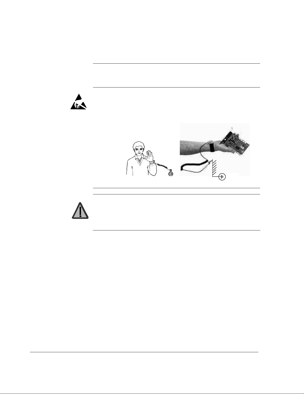
WARNING! The printed circuit boards contain components sensitive to
electrostatic discharge. Wear a grounding wrist band when handling
the boards. Do not touch the boards unnecessarily.
Use grounding strip:
ABB order no.: 3ADV050035P0001
WARNING! Handle the fiber optic cables with care. When unplugging
optic cables, always grab the connector, not the cable itself. Do not
touch the ends of the fibers with bare hands as the fiber is extremely
sensitive to dirt. The minimum allowed bend radius is 35 mm (1.38 in.).
Safety instructions
3ADW000193R0701 DCS800 Firmware Manual e g
Page 7

Mechanical installation
7
These notes are intended for all who install the drive. Handle the unit
carefully to avoid damage and injury.
WARNING!
•
DCS800 sizes D4 ... D7: The drive is heavy. Do not lift it alone. Do
not lift the unit by the front cover. Place units D4 and D5 only on its
back.
DCS800 sizes D5 ... D7: The drive is heavy. Lift the drive by the
lifting lugs only. Do not tilt the unit. The unit will overturn from a tilt
of about 6 degrees.
•
Make sure that dust from drilling does not enter the drive when
installing. Electrically conductive dust inside the unit may cause
damage or lead to malfunction.
•
•
Ensure sufficient cooling.
Do not fasten the drive by riveting or welding.
Safety instructions
3ADW000193R0701 DCS800 Firmware Manual e g
Page 8
8
Operation
These warnings are intended for all who plan the operation of the drive
or operate the drive. Ignoring the instructions can cause physical injury
or death and/or damage to the equipment.
WARNING!
•
Before adjusting the drive and putting it into service, make sure
that the motor and all driven equipment are suitable for operation
throughout the speed range provided by the drive. The drive can
be adjusted to operate the motor at speeds above and below the
base speed.
•
Do not control the motor with the disconnecting device
(disconnecting mains); instead, use the control panel keys
, or commands via the I/O board of the drive.
•
Mains connection
You can use a disconnect switch (with fuses) to disconnect the
electrical components of the drive from the mains for installation
and maintenance work. The type of disconnect switch used must
be as per EN 60947-3, Class B, so as to comply with EU
regulations, or a circuit-breaker type which switches off the load
circuit by means of an auxiliary contact causing the breaker's main
contacts to open. The mains disconnect must be locked in its
"OPEN" position during any installation and maintenance work.
•
EMERGENCY STOP buttons must be installed at each control
desk and at all other control panels requiring an emergency stop
function. Pressing the STOP button on the control panel of the
drive will neither cause an emergency stop of the motor, nor will
the drive be disconnected from any dangerous potential.
To avoid unintentional operating states, or to shut the unit down in
case of any imminent danger according to the standards in the
safety instructions it is not sufficient to merely shut down the drive
via signals "RUN", "drive OFF" or "Emergency Stop" respectively
"control panel" or "PC tool".
•
Intended use
The operating instructions cannot take into consideration every
possible case of configuration, operation or maintenance. Thus,
they mainly give such advice only, which is required by qualified
personnel for normal operation of the machines and devices in
industrial installations.
If in special cases the electrical machines and devices are intended for use in non-industrial installations - which may require
stricter safety regulations (e.g. protection against contact by
children or similar) - these additional safety measures for the
installation must be provided by the customer during assembly.
and
Safety instructions
3ADW000193R0701 DCS800 Firmware Manual e g
Page 9

9
Note:
•
When the control location is not set to Local (L not shown in the
status row of the display), the stop key on the control panel will not
stop the drive. To stop the drive using the control panel, press the
LOC/REM key and then the stop key
.
Safety instructions
3ADW000193R0701 DCS800 Firmware Manual e g
Page 10

10
Table of contents
Safety instructions 3
What this chapter contains......................................................................................................... 3
To which products this chapter applies ...................................................................................... 3
Usage of warnings and notes.....................................................................................................3
Installation and maintenance work............................................................................................. 4
Grounding.......................................................................................................................5
Mechanical installation ............................................................................................................... 7
Operation ................................................................................................................................... 8
Table of contents 10
Introduction 23
Chapter overview.......................................................................................................... 23
Before You Start ........................................................................................................... 23
What this manual contains ........................................................................................... 23
Start-up 24
Chapter overview.......................................................................................................... 24
General.........................................................................................................................24
Start-up procedure ................................................................................................................... 25
Tools............................................................................................................................. 25
Checking with the power switched off .......................................................................... 25
Checking with the power switched on .......................................................................... 27
Commissioning a DCS800 ....................................................................................................... 28
Connect DCS800 to PC with DriveWindow Light..................................................................... 28
Commissioning a DCS800 with the wizard .............................................................................. 29
Commissioning a DCS800 with DriveWindow.......................................................................... 30
Requirements ............................................................................................................... 30
01, 02 Macro assistant / Name plate data .................................................................... 30
03 Autotuning field current controller............................................................................ 31
04 Autotuning armature current controller .................................................................... 31
05 Speed feedback assistant ....................................................................................... 32
Analog tacho fine tune procedure ................................................................ 32
06 Autotuning speed controller..................................................................................... 32
07 Field weakening assistant ....................................................................................... 33
Manual tuning........................................................................................................................... 34
I/O configuration ........................................................................................................... 34
Field current controller.................................................................................................. 34
Armature current controller........................................................................................... 35
Control principle ........................................................................................... 35
Manual tuning............................................................................................... 36
Analog tacho................................................................................................................. 41
Manual tuning............................................................................................... 42
Speed controller ........................................................................................................... 42
Basics........................................................................................................... 42
Manual tuning............................................................................................... 43
EMF controller .............................................................................................................. 45
Table of contents
3ADW000193R0701 DCS800 Firmware Manual e g
Page 11

11
Basics............................................................................................................45
Manual tuning................................................................................................45
Flux linearization............................................................................................................47
Basics............................................................................................................47
Manual tuning................................................................................................48
Thyristor diagnosis ........................................................................................................50
Basics............................................................................................................50
Check all thyristors........................................................................................50
Check individual firing pulses........................................................................50
Firmware description 52
Chapter overview...........................................................................................................52
Identification of the firmware versions ...........................................................................52
Start / stop sequences ..............................................................................................................53
General..........................................................................................................................53
Switch on sequence ......................................................................................................53
Start the drive ................................................................................................................54
Stop the drive ................................................................................................................55
Field excitation ..........................................................................................................................58
General..........................................................................................................................58
Field Reversal................................................................................................................58
Field control...................................................................................................58
Field reference hysteresis .............................................................................59
Force field current direction...........................................................................59
Reversal time ................................................................................................59
Bumpless transition.......................................................................................59
Optitorque......................................................................................................................59
Field current reference gain ..........................................................................59
Field current monitoring.................................................................................................60
Field minimum trip.........................................................................................60
Flux reversal..................................................................................................60
Field reversal hysteresis................................................................................60
Field reversal active ......................................................................................60
Field Heating .................................................................................................................60
Overview .......................................................................................................60
Modes of operation........................................................................................61
E-stop............................................................................................................62
Field exciter mode.....................................................................................................................63
General..........................................................................................................................63
Large field exciter controlled by a DCS800 armature converter....................................63
Parameters to be set in the DCS800 armature converter: ............................64
Parameters to be set in large field exciters: ..................................................64
Field current autotuning for large field exciters: ............................................65
Stand alone field exciter ................................................................................................66
Parameters to be set in the stand alone field exciter: ...................................66
Field current autotuning for stand alone field exciter:....................................67
DC-breaker, DC-contactor ........................................................................................................68
General..........................................................................................................................68
HVCB controlled externally, DC-breaker controlled by the drive...................................68
DC-contactor US version ..........................................................................................................69
Table of contents
3ADW000193R0701 DCS800 Firmware Manual e g
Page 12

12
AC- and DC-breaker controlled by the drive................................................................. 71
No AC-breaker, DC-breaker controlled by the drive ..................................................... 72
AC-breaker controlled by the drive, DC-breaker controlled externally.......................... 73
No AC-breaker, DC-breaker controlled externally ........................................................ 74
Command Trip DC-breaker .......................................................................................... 74
Dynamic braking ...................................................................................................................... 75
General.........................................................................................................................75
Operation...................................................................................................................... 75
Activation...................................................................................................... 75
Function........................................................................................................ 75
Deactivation.................................................................................................. 76
Position counter ....................................................................................................................... 78
General.........................................................................................................................78
Counting procedure ...................................................................................................... 78
Synchronization ............................................................................................................ 78
I/O configuration 81
Chapter overview.......................................................................................................... 81
Digital inputs (DI’s) ................................................................................................................... 81
SDCS-CON-4 / SDCS-IOB-2........................................................................................ 81
st
and 2nd RDIO-01 ....................................................................................................... 81
1
Configuration ................................................................................................................ 82
Digital outputs (DO’s) ............................................................................................................... 84
SDCS-CON-4 / SDCS-IOB-2........................................................................................ 84
st
and 2nd RDIO-01 ....................................................................................................... 84
1
Configuration ................................................................................................................ 85
Analog inputs (AI’s) .................................................................................................................. 87
SDCS-CON-4 ............................................................................................................... 87
SDCS-IOB-3 ................................................................................................................. 87
st
RAIO-01 ................................................................................................................... 88
1
nd
RAIO-01................................................................................................................... 88
2
Configuration ................................................................................................................ 89
Scaling.......................................................................................................................... 89
Analog outputs (AO’s) .............................................................................................................. 91
SDCS-CON-4 / SDCS-IOB-3........................................................................................ 91
st
RAIO-01 ................................................................................................................... 91
1
nd
RAIO-01................................................................................................................... 92
2
Configuration ................................................................................................................ 92
Scaling.......................................................................................................................... 93
Communication 94
Chapter overview.......................................................................................................... 94
DCSLink with SDCS-DSL-4 ..................................................................................................... 94
General.........................................................................................................................94
Excitation, commissioning a FEX-4.......................................................................................... 94
Layout FEX-4................................................................................................................ 94
Layout SDCS-DSL-4 .................................................................................................... 94
Set the FEX-4 type ....................................................................................................... 95
Set the node numbers, transmission speed and the communication supervision........ 95
Set the DCSLink ........................................................................................................... 96
Table of contents
3ADW000193R0701 DCS800 Firmware Manual e g
Page 13

13
Set the supply of the FEX-4...........................................................................................97
Checking the FEX-4 ......................................................................................................97
Master-follower, commissioning................................................................................................98
Set the DCSLink hardware ............................................................................................98
Set the node ID numbers and transmission speed........................................................99
Activate the mailboxes...................................................................................................99
Activate the communication supervision .......................................................................99
Send and receive values .............................................................................................100
Firmware structure.......................................................................................................101
Additional settings .......................................................................................................102
Drive-to-drive communication .................................................................................................103
Set the DCSLink hardware ..........................................................................................103
Set the node ID numbers and transmission speed......................................................104
Activate the mailboxes.................................................................................................104
Activate the communication supervision .....................................................................104
Send and receive values .............................................................................................105
12-pulse ..................................................................................................................................106
Set the DCSLink hardware ..........................................................................................106
Set the node numbers, transmission speed and the communication supervision.......107
DDCS channels with SDCS-COM-8 .......................................................................................108
General........................................................................................................................108
Integer scaling on the DDCS link.................................................................................108
Ch0 communication to overriding control................................................................................109
ABB overriding control.................................................................................................109
Parameter setting example..........................................................................................109
Received data set table...............................................................................................110
Transmitted data set table...........................................................................................111
Fieldbus communication (N-type)................................................................................111
Ch1 I/O devices ......................................................................................................................112
Ch2 Master-follower link..........................................................................................................112
General........................................................................................................................112
Link configuration ........................................................................................................112
Master..........................................................................................................................112
Followers .....................................................................................................................113
Firmware structure.......................................................................................................113
Toggle between speed- and torque control.................................................................115
Follower diagnostics....................................................................................................115
Master-follower link specification.................................................................................115
Ch3 commissioning and maintenance tools............................................................................116
DriveWindow ...............................................................................................................116
Ethernet communication for monitoring with Ethernet adapter NETA-01 ...............................117
General........................................................................................................................117
NETA-01 - DCS800 .....................................................................................................117
Related documentation................................................................................................117
NETA-01 configuration ................................................................................................117
Mechanical and electrical installation ..........................................................................118
Drive configuration.......................................................................................................118
CANopen communication with fieldbus adapter RCAN-01 .....................................................119
General........................................................................................................................119
RCAN-01 - DCS800 ....................................................................................................119
Table of contents
3ADW000193R0701 DCS800 Firmware Manual e g
Page 14

14
Related documentation............................................................................................... 119
Overriding control configuration.................................................................................. 119
EDS file....................................................................................................................... 119
Mechanical and electrical installation ......................................................................... 119
Drive configuration...................................................................................................... 119
Parameter setting example 1 using group 51............................................................. 119
Further information ..................................................................................................... 121
Parameter setting example 2 using groups 90 and 92 ............................................... 122
Switch on sequence ................................................................................................... 124
ControlNet communication with fieldbus adapter RCNA-01................................................... 125
General....................................................................................................................... 125
RCNA-01 - DCS800 ................................................................................................... 125
Related documentation............................................................................................... 125
Overriding control configuration.................................................................................. 125
EDS file....................................................................................................................... 125
Mechanical and electrical installation ......................................................................... 125
Drive configuration...................................................................................................... 125
Parameter setting example 1 using ABB Drives assembly......................................... 125
Parameter setting example 2 using Vendor specific assembly .................................. 127
Setting of parameter groups 51, 90 and 92 ................................................................ 128
Further information ..................................................................................................... 128
Switch on sequence ................................................................................................... 128
DeviceNet communication with fieldbus adapter RDNA-01 ................................................... 129
General....................................................................................................................... 129
RDNA-01 - DCS800 ................................................................................................... 129
Related documentation............................................................................................... 129
Overriding control configuration.................................................................................. 129
EDS file....................................................................................................................... 129
Mechanical and electrical installation ......................................................................... 129
Drive configuration...................................................................................................... 129
Parameter setting example 1 using ABB Drives assembly......................................... 129
Parameter setting example 2 using User specific assembly ...................................... 131
Setting of parameter groups 51, 90 and 92 ................................................................ 132
Further information ..................................................................................................... 132
Switch on sequence ................................................................................................... 132
Ethernet/IP communication with fieldbus adapter RETA-01 .................................................. 133
General....................................................................................................................... 133
RETA-01 - DCS800 .................................................................................................... 133
Related documentation............................................................................................... 133
EDS file....................................................................................................................... 133
Mechanical and electrical installation ......................................................................... 133
Drive configuration...................................................................................................... 133
Parameter setting example using Ethernet/IP ABB Drives communication profile..... 133
Up to 4 data words ..................................................................................................... 135
Up to 12 data words ................................................................................................... 135
Switch on sequence ................................................................................................... 138
Modbus (RTU) communication with fieldbus adapter RMBA-01 ............................................ 139
General....................................................................................................................... 139
RMBA-01 - DCS800 ................................................................................................... 139
Related documentation............................................................................................... 139
Table of contents
3ADW000193R0701 DCS800 Firmware Manual e g
Page 15

15
Mechanical and electrical installation ..........................................................................139
Drive configuration.......................................................................................................139
Parameter setting example ….....................................................................................139
… when controlling a drive ..........................................................................................139
… when used for monitoring only................................................................................141
Setting of PLC, parameter groups 90 and 92 ..............................................................143
Switch on sequence ....................................................................................................143
Modbus/TCP communication with fieldbus adapter RETA-01 ................................................144
General........................................................................................................................144
RETA-01 - DCS800 .....................................................................................................144
Related documentation................................................................................................144
Mechanical and electrical installation ..........................................................................144
Drive configuration.......................................................................................................144
Parameter setting example using Modbus/TCP ..........................................................144
Switch on sequence ....................................................................................................146
Profibus communication with fieldbus adapter RPBA-01........................................................147
General........................................................................................................................147
RPBA-01 - DCS800.....................................................................................................147
Related documentation................................................................................................147
Overriding control configuration...................................................................................147
Mechanical and electrical installation ..........................................................................147
Drive configuration.......................................................................................................147
Parameter setting example 1 using PPO Type 1 ........................................................147
Parameter setting example 2 using PPO types 2, 4 and 5..........................................148
Communication via group 51.......................................................................................149
Communication via group 90 and group 92.................................................................150
Switch on sequence ....................................................................................................151
Data set table..........................................................................................................................152
Adaptive Program (AP) 153
Chapter overview.........................................................................................................153
What is the Adaptive Program.....................................................................................153
Features ......................................................................................................................153
How to build the program ............................................................................................154
How to connect the Application Program with the firmware ........................................154
Block Parameter Set for block 1 ..................................................................................155
How to control the execution of the program...............................................................156
DWL AP ..................................................................................................................................157
General........................................................................................................................157
Important keys and buttons .........................................................................................157
Program modes...........................................................................................................157
Change to Edit mode...................................................................................................157
Insert function blocks...................................................................................................158
Connect function blocks ..............................................................................................159
Set the Time level........................................................................................................161
Saving AP applications................................................................................................161
Function blocks .......................................................................................................................162
General rules...............................................................................................................162
Block inputs .................................................................................................................162
Block input attributes...................................................................................163
Table of contents
3ADW000193R0701 DCS800 Firmware Manual e g
Page 16

16
Parameter value as an integer input .......................................................... 164
How the block handles the input ................................................................ 164
How to select the input ............................................................................... 164
Constant as an integer input ...................................................................... 165
How to set and connect the input ............................................................... 165
Parameter value as a boolean input........................................................... 166
How the block handles the input ................................................................ 166
Constant as a boolean input....................................................................... 167
How to set and connect the input ............................................................... 167
String input ................................................................................................. 167
How to select the input ............................................................................... 167
Function blocks ...................................................................................................................... 168
ABS ............................................................................................................................ 168
ADD ............................................................................................................................ 169
AND ............................................................................................................................ 169
Bitwise ........................................................................................................................ 170
Bset ............................................................................................................................ 171
Compare..................................................................................................................... 171
Count .......................................................................................................................... 172
D-Pot .......................................................................................................................... 172
Event .......................................................................................................................... 173
Filter............................................................................................................................ 173
Limit ............................................................................................................................ 174
MaskSet...................................................................................................................... 174
Max............................................................................................................................. 175
Min.............................................................................................................................. 175
MulDiv......................................................................................................................... 175
NotUsed...................................................................................................................... 176
OR .............................................................................................................................. 176
ParRead ..................................................................................................................... 176
ParWrite...................................................................................................................... 177
PI ................................................................................................................................ 177
PI-Bal.......................................................................................................................... 178
Ramp .......................................................................................................................... 178
Sqrt ............................................................................................................................. 179
SqWav ........................................................................................................................ 179
SR............................................................................................................................... 180
Switch-B ..................................................................................................................... 180
Switch-I....................................................................................................................... 181
TOFF .......................................................................................................................... 181
TON ............................................................................................................................ 182
Trigg ........................................................................................................................... 182
XOR............................................................................................................................ 183
Diagram.................................................................................................................................. 184
Signal and parameter list 185
Signals and parameters ......................................................................................................... 185
Signal groups list.................................................................................................................... 185
Parameter groups list ............................................................................................................. 187
Signal and parameter list ....................................................................................................... 190
Table of contents
3ADW000193R0701 DCS800 Firmware Manual e g
Page 17

17
Group 1........................................................................................................................190
Physical actual values.................................................................................190
Group 2........................................................................................................................194
Speed controller signals..............................................................................194
Group 3........................................................................................................................198
Reference actual values..............................................................................198
Group 4........................................................................................................................201
Information ..................................................................................................201
Group 5........................................................................................................................209
Analog I/O ...................................................................................................209
Group 6........................................................................................................................210
Drive logic signals .......................................................................................210
Group 7........................................................................................................................216
Control words ..............................................................................................216
Group 8........................................................................................................................222
Status / limit words ......................................................................................222
Group 9........................................................................................................................228
Fault / alarm words......................................................................................228
Group 10......................................................................................................................244
Start / stop select ........................................................................................244
Group 11......................................................................................................................257
Speed reference inputs ...............................................................................257
Group 12......................................................................................................................264
Constant speeds .........................................................................................264
Group 13......................................................................................................................265
Analog inputs ..............................................................................................265
Group 14......................................................................................................................269
Digital outputs .............................................................................................269
Group 15......................................................................................................................271
Analog outputs ............................................................................................271
Group 16......................................................................................................................273
System control inputs..................................................................................273
Group 19......................................................................................................................276
Data storage................................................................................................276
Group 20......................................................................................................................278
Limits...........................................................................................................278
Group 21......................................................................................................................282
Start / stop...................................................................................................282
Group 22......................................................................................................................286
Speed ramp.................................................................................................286
Group 23......................................................................................................................289
Speed reference..........................................................................................289
Group 24......................................................................................................................294
Speed control ..............................................................................................294
Group 25......................................................................................................................299
Torque reference.........................................................................................299
Group 26......................................................................................................................300
Torque reference handling ..........................................................................300
Group 30......................................................................................................................304
Fault functions.............................................................................................304
Table of contents
3ADW000193R0701 DCS800 Firmware Manual e g
Page 18

18
Group 31..................................................................................................................... 315
Motor 1 temperature................................................................................... 315
Group 34..................................................................................................................... 317
DCS800 Control Panel display................................................................... 317
Group 40..................................................................................................................... 318
PID control.................................................................................................. 318
Group 42..................................................................................................................... 321
Brake control .............................................................................................. 321
Group 43..................................................................................................................... 327
Current control............................................................................................ 327
Group 44..................................................................................................................... 333
Field excitation ........................................................................................... 333
Group 45..................................................................................................................... 340
Field converter settings .............................................................................. 340
Group 47..................................................................................................................... 347
12-pulse operation...................................................................................... 347
Group 49..................................................................................................................... 348
Shared motion ............................................................................................ 348
Group 50..................................................................................................................... 360
Speed measurement .................................................................................. 360
Group 51..................................................................................................................... 367
Fieldbus...................................................................................................... 367
Group 52..................................................................................................................... 368
Modbus....................................................................................................... 368
Group 60, …, 69 ......................................................................................................... 369
Application program parameters ................................................................ 369
Group 70..................................................................................................................... 370
DDCS control ............................................................................................. 370
Group 71..................................................................................................................... 375
Drivebus ..................................................................................................... 375
Group 83..................................................................................................................... 375
Adaptive Program control........................................................................... 375
Group 84..................................................................................................................... 377
Adaptive Program....................................................................................... 377
Group 85..................................................................................................................... 380
User constants ........................................................................................... 380
Group 86..................................................................................................................... 382
Adaptive Program outputs.......................................................................... 382
Group 88..................................................................................................................... 383
Internal ....................................................................................................... 383
Group 90..................................................................................................................... 385
Receiving data sets addresses 1 ............................................................... 385
Group 91..................................................................................................................... 387
Receiving data sets addresses 2 ............................................................... 387
Group 92..................................................................................................................... 388
Transmit data sets addresses 1 ................................................................. 388
Group 93..................................................................................................................... 390
Transmit data sets addresses 2 ................................................................. 390
Group 94..................................................................................................................... 391
DCSLink control ......................................................................................... 391
Table of contents
3ADW000193R0701 DCS800 Firmware Manual e g
Page 19

19
Group 97......................................................................................................................399
Measurement ..............................................................................................399
Group 98......................................................................................................................407
Option modules ...........................................................................................407
Group 99......................................................................................................................415
Start-up data ...............................................................................................415
DCS800 Control Panel operation 420
Chapter overview.........................................................................................................420
Start-up........................................................................................................................420
DCS800 Control Panel ................................................................................................420
Display overview..........................................................................................................421
General display features..............................................................................................421
Output mode................................................................................................................422
Other modes................................................................................................................423
Maintenance................................................................................................................428
Fault tracing 429
Chapter overview.........................................................................................................429
General........................................................................................................................429
Fault modes ................................................................................................429
Converter protection ...............................................................................................................429
Auxiliary undervoltage .................................................................................................429
Armature overcurrent...................................................................................................429
Converter overtemperature .........................................................................................429
Auto-reclosing (mains undervoltage)...........................................................................430
Mains synchronism......................................................................................................431
Mains overvoltage .......................................................................................................431
Communication loss ....................................................................................................431
Fan, field and mains contactor acknowledge ..............................................................432
External fault................................................................................................................432
Bridge reversal ............................................................................................................433
Analog input monitor....................................................................................................433
Motor protection ......................................................................................................................435
Armature overvoltage ..................................................................................................435
Residual current detection...........................................................................................435
Measured motor temperature ......................................................................................435
Klixon...........................................................................................................................438
Motor thermal model....................................................................................................438
Field overcurrent..........................................................................................................441
Armature current ripple................................................................................................441
Speed feedback monitor..............................................................................................442
Stall protection.............................................................................................................443
Overspeed protection ..................................................................................................443
Current rise..................................................................................................................444
Field undercurrent .......................................................................................................444
Tacho / pulse encoder polarity ....................................................................................444
Tacho range ................................................................................................................444
Status messages ....................................................................................................................445
Display of status, fault and alarm signals ....................................................................445
Table of contents
3ADW000193R0701 DCS800 Firmware Manual e g
Page 20

20
Categories of signals and display options .................................................. 445
General messages ..................................................................................................... 446
Power-up errors (E) .................................................................................................... 446
Fault signals (F).......................................................................................................... 447
SDCS-COM-8 messages ........................................................................... 464
Alarm signals (A) ........................................................................................................ 465
Disappearing system alarm ........................................................................................ 475
User defined alarm by Adaptive Program................................................................... 475
Notices........................................................................................................................ 477
Appendix A: Firmware structure diagrams 479
Appendix B: SDCS-CON-4 Terminal Allocation 484
Appendix C: Index of signals and parameters 485
Table of contents
3ADW000193R0701 DCS800 Firmware Manual e g
Page 21

21
Chapters not yet available
3ADW000193R0701 DCS800 Firmware Manual e g
Page 22

22
3ADW000193R0701 DCS800 Firmware Manual e g
Page 23

Introduction
Chapter overview
Before You Start
What this manual contains
This chapter describes the purpose, contents and the intended use of this manual.
The purpose of this manual is to provide you with the information necessary to
control and program the drive.
Study carefully the Safety instructions at the beginning of this manual before
attempting any work on or with the drive. Read through this manual before starting-
up the drive. The installation and commissioning instructions given in the DCS800
Hardware Manual and DCS800 Quick Guide must also be read before proceeding.
This manual describes the standard DCS800 firmware.
The Safety instructions can be found at the beginning of this manual.
Introduction to this manual
to this manual.
Start-up
Firmware description
firmware.
I/O configuration
inputs and outputs with different hardware possibilities.
Communication
Adaptive Program (AP)
and instructs how to build a program.
Signal and parameter list
DCS800 Control Panel operation
DCS800 Control Panel.
Fault Tracing
Appendix A: Firmware structure diagram
Appendix B: SDCS-CON-4 Terminal Allocation
Appendix C: Index of signal and parameters
, this chapter describes the basic start-up procedure of the drive.
, this chapter describes the protections and fault tracing of the drive.
23
, the chapter you are currently reading, introduces you
, this chapter describes how to control the drive with standard
, this chapter describes the I/O configuration of digital and analog
, this chapter describes the communication capabilities of the drive.
, this chapter describes the basics of the Adaptive Program
, this chapter contains all signals and parameters.
, this chapter describes the handling of the
Introduction to this manual
3ADW000193R0701 DCS800 Firmware Manual e g
Page 24

24
Start-up
Chapter overview
General
This chapter describes the basic start-up procedure of the drive. A more detailed
description of the signals and parameters involved in the procedure can be found
in section Signal and parameter list.
The drive can be operated:
The following start-up procedure uses DriveWindow (for further information about
DriveWindow, consult its online help). However, parameters can also be changed
with DriveWindow Light or the DCS800 Control Panel.
The start-up procedure includes actions that need only be taken when powering up
the drive for the first time in a new installation (e.g. entering the motor data). After
the start-up, the drive can be powered up without using these start-up functions
again. The start-up procedure can be repeated later if the start-up data needs to be
altered.
Refer to section Fault tracing
problem, disconnect mains and wait for 5 minutes before attempting any work on
the drive, the motor, or the motor cables.
locally from DriveWindow, DriveWindow Light or DCS800 Control Panel
respectively remote from local I/O or overriding control.
in case problems should arise. In case of a major
Start-up
3ADW000193R0701 DCS800 Firmware Manual e g
Page 25

Start-up procedure
25
The Safety Instructions
at the beginning of this manual have to be observed with
extreme care during the start-up procedure!
The start-up procedure should only be carried out by a qualified electrician.
Check the mechanical and electrical installation the drive according to the DCS800
Hardware Manual.
Tools
For drive commissioning following software tools are mandatory:
DriveWindow Light including commissioning wizard and DWL AP for
Adaptive Program and
DriveWindow for fast drive monitoring using SDCS-COM-8.
For drive commissioning following tools are mandatory in addition to standard tools:
An oscilloscope including memory function with either galvanically isolating
transformer or isolating amplifier for safe measurements.
A clamp on current probe. In case the scaling of the DC load current needs
to be checked it must be a DC clamp on current probe.
A voltmeter.
Make sure that all equipment in use is suitable for the voltage level applied to the
power part!
Checking with the power switched off
Check the settings of:
the main breaker (e.g. overcurrent = 1.6 * I
time for thermal tripping = 10 s),
time, overcurrent, thermal and voltage relays,
the earth fault protection (e.g. Bender relay)
Check the insulation of the mains voltage cables or busbars between the
secondary side of the dedicated transformer and the drive:
disconnect the dedicated transformer from its incoming voltage,
check that all circuits between the mains and the drive (e.g. control /
auxiliary voltage) are disconnected,
measure the insulation resistance between L1 - L2, L1 - L3, L2 - L3, L1 -
PE, L2 - PE, L3 - PE,
the result should be M:s
Check the installation:
crosscheck the wiring with the drawings,
check the mechanical mounting of the motor and pulse encoder or analog
tacho,
make sure that the motor is connected in a correct way (armature, field,
serial windings, cable shields),
check the connections of the motor fan if existing,
make sure that the converter fan is connected correctly especially in
modules size D6 and D7 were star or delta connection is possible,
, short circuit current = 10 * In,
n
Start-up
3ADW000193R0701 DCS800 Firmware Manual e g
Page 26
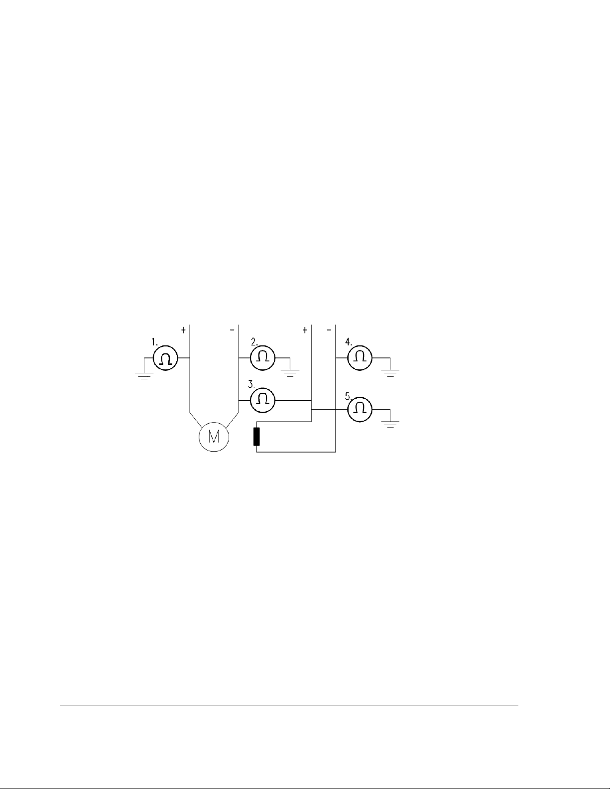
26
if a pulse encoder is used make sure that pulse encoder's auxiliary voltage
connection corresponds to its voltage and that the channel connection
corresponds to correct direction of rotation,
check that the shielding of the pulse encoder's cable is connected to the TE
bar of the DCS800,
if an analog tacho is used make sure that it is connected to the proper
voltage input at the SDCS-CON-4:
X3:1 - X3:4 (90 - 270 V)
X3:2 - X3:4 (30 - 90 V)
X3:3 - X3:4 (8 - 30 V)
for all other cables make sure that both ends of the cables are connected
and they do not cause any damage or danger when power is being
switched on
Measuring the insulation resistance of the motor cables and the motor:
isolate the motor cables from the drive before testing the insulation
resistance or voltage withstand of the cables or the motor,
Instructions how to measure the insulation resistance
measure the insulation resistance between:
1. + cables and PE,
2. - cables and PE,
3. armature cables and field cables,
4. field - cable and PE,
5. field + cable and PE,
the result should be M:s
Setting of Jumpers:
The boards of the DCS800 include jumpers to adapt the boards to different
applications. The position of the jumpers must be checked before connecting
voltage. For specific jumper settings consult the DCS800 Hardware Manual.
Start-up
3ADW000193R0701 DCS800 Firmware Manual e g
Page 27

Drive data
Check following items for each drive and mark the differences in the delivery
documents:
motor, analog tacho or pulse encoder and cooling fan rating plates data,
direction of motor rotation,
maximum and minimum speed and if fixed speeds are used,
speed scaling factors:
e.g. gear ratio, roll diameter,
acceleration and deceleration times,
operating modes:
e.g. stop mode, E-stop mode,
the amount of motors connected
Checking with the power switched on
There is dangerous voltage inside the cabinet!
Switching the power on:
prior to connecting the voltage proceed as follows:
1. ensure that all the cable connections are checked and that the
connections can't cause any danger,
2. close all doors of enclosed converter before switching power on,
3. be ready to trip the supply transformer if anything abnormal occurs,
4. switch the power on
Measurements made with power on:
check the operation of the auxiliary equipment,
check the circuits for external interfaces on site:
1. E-stop circuit,
2. remote control of the main breaker,
3. signals connected to the control system,
4. other signals which remain to be checked
Connecting voltage to the drive:
check from the delivery diagrams the type of boards and converters which
are used in the system,
check all time relay and breaker settings,
close the supply disconnecting device (check the connection from the
delivery diagrams),
close all protection switches one at a time and measure for proper voltage
27
Start-up
3ADW000193R0701 DCS800 Firmware Manual e g
Page 28
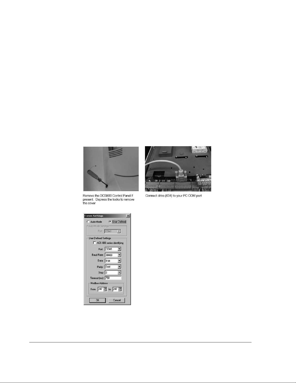
28
Commissioning a DCS800
Nominal values of the converter can be found in group 4, check following signals:
ConvNomVolt (4.04), nominal AC converter voltage in V read from
TypeCode (97.01) or S ConvScaleVolt (97.03),
ConvNomCur (4.05), nominal converter DC current in A read from
TypeCode (97.01) or S ConvScaleCur (97.02),
ConvType (4.14), recognized converter type read from TypeCode (97.01),
QuadrantType (4.15), recognized converter quadrant type read from
TypeCode (97.01) or S BlockBrdg2 (97.07),
MaxBridgeTemp (4.17), maximum bridge temperature in degree centigrade
read from TypeCode (97.01) or S MaxBrdgTemp (97.04)
If signals are not correct adapt them, see group 97 in this manual.
Connect DCS800 to PC with DriveWindow Light
Connect a normal serial cable from the PC COM port to X34 on the drive:
Start DriveWindow Light and check the communication settings:
Example with COM1.
Start-up
3ADW000193R0701 DCS800 Firmware Manual e g
Page 29
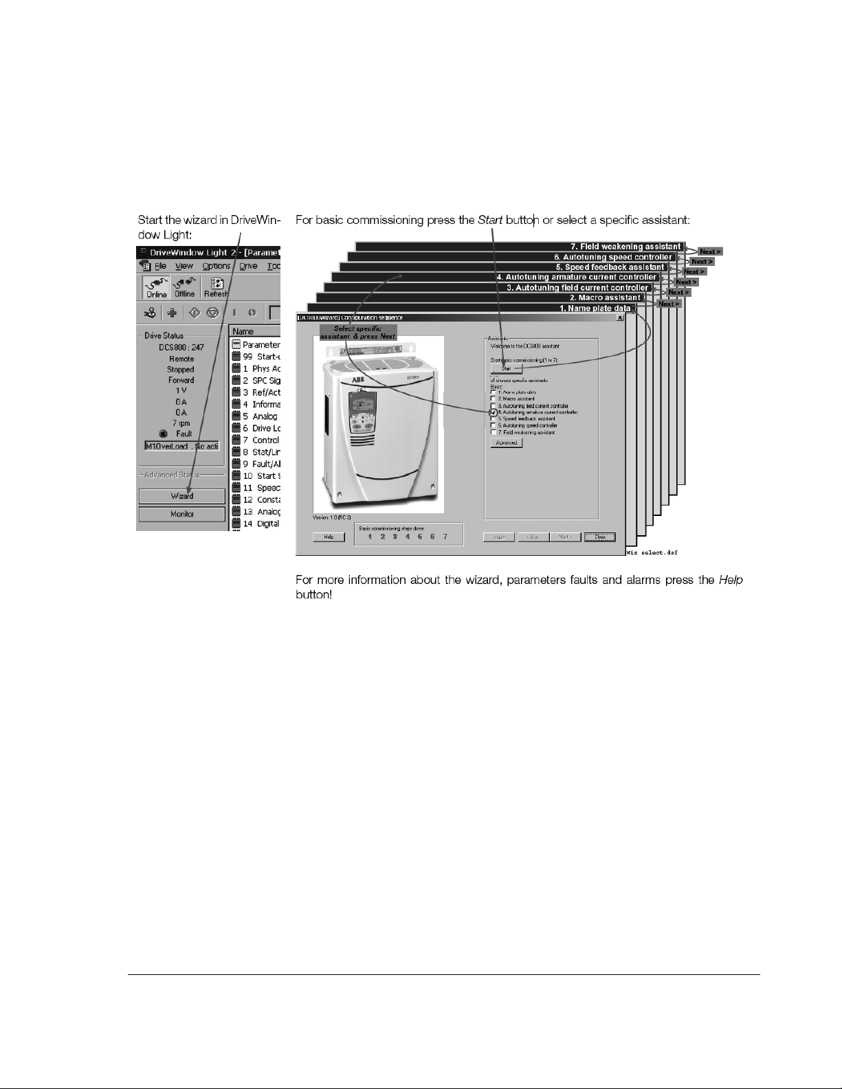
29
Commissioning a DCS800 with the wizard
To launch the commissioning wizard start DriveWindow Light and press the Wizard
button:
Start-up
3ADW000193R0701 DCS800 Firmware Manual e g
Page 30

30
Commissioning a DCS800 with DriveWindow
Requirements
1. Before starting with the commissioning, connect the drive (via Ch3 on
SDCS-COM-8) with DriveWindow (via e.g. NDPA-02 and NDPC-12). All
workspaces are ‘online’ workspaces, thus use Ch3 NodeAddr (70.22) = 1.
2. The preconfigured workspaces are available from Your local ABB agent or
can be found - after the DCS800 CD (tools CD) is installed - under:
Location of workspaces
01, 02 Macro assistant / Name plate data
1. Open the workspace 01, 02 DCS800 Name plate data & macro
assistant.dww
2. Set all parameters to default by means of ApplMacro (99.08) = Factory and
ApplRestore (99.07) = Yes. Check with MacroSel (8.10).
3. Enter the motor data, the mains (supply) data and the most important
protections [M1SpeedMin (20.01), M1SpeedMax (20.02), ArmOvrCurLev
(30.09), M1OvrSpeed (30.16), Language (99.01), M1NomVolt (99.02),
M1NomCur (99.03), M1BaseSpeed (99.04), NomMainsVolt (99.10) and
M1NomFldCur (99.11)].
4. After filling out the parameters it is - in most cases - possible to turn the
motor for the first time.
5. Select an application macro by means of ApplMacro (99.08) = <macro>
and ApplRestore (99.07) = Yes. Check with MacroSel (8.10).
1
.
Start-up
3ADW000193R0701 DCS800 Firmware Manual e g
Page 31

03 Autotuning field current controller
1. Open the workspace 03 DCS800 Autotuning field current controller.dww1.
2. Enter the field circuit data [FldCtrlMode (44.01), M1NomFldCur (99.11) and
M1UsedFexType (99.12)].
3. Switch the drive to local mode (DriveWindow, DCS800 Control Panel or
local I/O).
4. Start the autotuning by means of ServiceMode (99.06) = FieldCurAuto and
set On within 20 s.
5. During the autotuning the main respectively field contactor will be closed,
the field circuit is measured by means of increasing the field current to
nominal field current and the field current control parameters are set. The
armature current is not released while the autotuning is active and thus the
motor should not turn.
6. When the autotuning is finished successfully, check M1KpFex (44.02),
M1TiFex (44.03) and M1PosLimCtrl (45.02) - parameters set by the
autotuning - for confirmation.
7. If the autotuning fails A121 AutotuneFail is set. For more details check
Diagnosis (9.11) and repeat the autotuning.
04 Autotuning armature current controller
1. Open the workspace 04 DCS800 Autotuning armature current
controller.dww
1
.
2. Enter the basic current limitations and the motor nominal current [TorqMax
(20.05), TorqMin (20.06), M1CurLimBrdg1 (20.12), M1CurLimBrdg2 (20.13)
and M1NomCur (99.03)].
Attention:
Do not change the default values of M1ArmL (43.09) and M1ArmR (43.10)!
Changing them will falsify the results of the autotuning.
3. Switch the drive to local mode (DriveWindow, DCS800 Control Panel or
local I/O).
4. Start the autotuning by means of ServiceMode (99.06) = ArmCurAuto and
set On and Run within 20 s.
5. During the autotuning the main contactor will be closed, the armature circuit
is measured by means of armature current bursts and the armature current
control parameters are set. The field current is not released while the
autotuning is active and thus the motor should not turn, but due to
remanence in the field circuit about 40% of all motors will turn (create
torque). These motors have to be locked.
6. When the autotuning is finished successfully, check M1KpArmCur (43.06),
M1TiArmCur (43.07), M1DiscontCurLim (43.08), M1ArmL (43.09) and
M1ArmR (43.10) - parameters set by the autotuning - for confirmation.
7. If the autotuning fails A121 AutotuneFail is set. For more details check
Diagnosis (9.11) and repeat the autotuning.
31
Start-up
3ADW000193R0701 DCS800 Firmware Manual e g
Page 32

32
05 Speed feedback assistant
Analog tacho
fine tune
procedure
1. Open the workspace 05 DCS800 Speed feedback assistant.dww1.
2. Enter the EMF speed feedback parameters and - if applicable - the
parameters for pulse encoder 1, pulse encoder 2 or the analog tacho
[M1SpeedMin (20.01), M1SpeedMax (20.02), M1EncMeasMode (50.02),
M1SpeedFbSel (50.03), M1EncPulseNo (50.04), M1TachoVolt1000
(50.13), M1NomVolt (99.02) and M1BaseSpeed (99.04)].
3. Switch the drive to local mode (DriveWindow, DCS800 Control Panel or
local I/O).
4. Start the autotuning by means of ServiceMode (99.06) = SpdFbAssist and
set On and Run within 20 s.
5. The speed feedback assistant detects the kind of speed feedback - EMF,
pulse encoder 1, pulse encoder 2 or analog tacho - the drive is using.
6. During the autotuning the main contactor and the field contactor - if existing
- will be closed and the motor will run up to base speed [M1BaseSpeed
(99.04)]. During the whole procedure the drive will be in EMF speed control
despite the setting of M1SpeedFbSel (50.03).
7. When the autotuning is finished successfully, check M1SpeedFbSel (50.03)
- parameter set by the autotuning - for confirmation.
8. If the autotuning fails A121 AutotuneFail is set. For more details check
Diagnosis (9.11) and repeat the autotuning.
1. In case an a
nalog tacho is detected [M1SpeedFbSel (50.03) = Tacho] it is
recommended to fine tune the analog tacho.
2. Switch the drive to local mode (DriveWindow, DCS800 Control Panel or
local I/O).
3. Start the autotuning by means of ServiceMode (99.06) = TachFineTune
and set On and Run within 20 s.
4. Measure the motor speed with a hand held tacho and write the value into
M1TachoAdjust (50.12).
5. Check SpeedActTach (1.05) against SpeedRef4 (2.18).
6. Stop the autotuning by removing Run and On via the DriveWindow control
panel.
06 Autotuning speed controller
Start-up
1. Open the workspace 06 DCS800 Autotuning speed controller.dww1.
2. Enter the basic speed, torque and current limits, the speed filter times and
the motor base speed [M1SpeedMin (20.01), M1SpeedMax (20.02),
TorqMax (20.05), TorqMin (20.06), M1CurLimBrdg1 (20.12),
M1CurLimBrdg2 (20.13), SpeedErrFilt (23.06), SpeedErrFilt2 (23.11),
SpeedFiltTime (50.06) and M1BaseSpeed (99.04)].
Attention:
For better results set the filters, especially when using EMF speed
feedback.
3. Switch the drive to local mode (DriveWindow, DCS800 Control Panel or
local I/O).
4. Start the autotuning by means of ServiceMode (99.06) = SpdCtrlAuto and
set On and Run within 20 s.
5. During the autotuning the main contactor and the field contactor - if existing
- will be closed, the ramp is bypassed and torque respectively current limits
3ADW000193R0701 DCS800 Firmware Manual e g
Page 33

are valid. The speed controller is tuned by means of speed bursts up to
base speed [M1BaseSpeed (99.04)] and the speed controller parameters
are set.
Attention:
During the autotuning the torque and/or current limits will be reached.
6. When the autotuning is finished successfully, check KpS (24.03) and TiS
(24.09) - parameters set by the autotuning - for confirmation.
7. If the autotuning fails A121 AutotuneFail is set. For more details check
Diagnosis (9.11) and repeat the autotuning.
Attention:
The assistant is using the setting of M1SpeedFbSel (50.03). If using setting
Encoder, Encoder2 or Tacho make sure the speed feedback is working properly!
07 Field weakening assistant
1
: before opening the workspaces, the drive has to be connected to DriveWindow
1. Open the workspace 07 DCS800 Field weakening assistant.dww1.
2. Enter the motor data and the field circuit data [M1SpeedMin (20.01),
M1SpeedMax (20.02), M1FldMinTrip (30.12), FldCtrlMode (44.01),
M1NomVolt (99.02), M1BaseSpeed (99.04) and M1NomFldCur (99.11)].
3. Switch the drive to local mode (DriveWindow, DCS800 Control Panel or
local I/O).
4. Start the autotuning by means of ServiceMode (99.06) = EMF FluxAuto
and set On and Run via within 20 s.
5. During the autotuning the main contactor and the field contactor - if existing
- will be closed and the motor will run up to base speed [M1BaseSpeed
(99.04)]. The EMF controller data are calculated, the flux linearization is
tuned by means of a constant speed while decreasing the field current and
the EMF controller respectively flux linearization parameters are set.
6. When the autotuning is finished successfully, check KpEMF (44.09), TiEMF
(44.10), FldCurFlux40 (44.12), FldCurFlux70 (44.13) and FldCurFlux90
(44.14) - parameters set by the autotuning - for confirmation.
7. If the autotuning fails A121 AutotuneFail is set. For more details check
Diagnosis (9.11) and repeat the autotuning.
33
Start-up
3ADW000193R0701 DCS800 Firmware Manual e g
Page 34

34
Manual tuning
I/O configuration
To set the in- and outputs see chapter I/O configuration.
Field current controller
Manual tuning of the field current controller:
connect DriveWindow to the drive and choose local mode,
monitor Mot1FldCurRef (1.29) and FldCurRefM1 (3.30),
set M1FldMinTrip (30.12) = 0 %,
set M1FldRefMode (45.05) = M1FldRefExt,
give On via DriveWindow,
use M1FldRefExt (45.06) to step the field current controller,
tune the field current controller by means of M1KpFex (44.02) and M1TiFex
(44.03),
o steps size: about 2 % - 5 % of nominal field current (do not hit any
limits during the step and the step response, e.g. max. field current,
or supply voltage),
o step response time: 50 ms - 60 ms (count only from 10 % to 90 %),
o where to step: 30 %, 60 % and 80 % of nominal field current,
step reference
Field current controller step responses
optimal curve
p-part too low
p-part too high
i-part too short
Start-up
3ADW000193R0701 DCS800 Firmware Manual e g
Page 35

35
DriveWindow manual tuning field current controller
set M1FldRefExt (45.06) = 0 %,
remove On via DriveWindow,
set M1FldMinTrip (30.12) and M1FldRefMode (45.05) back to their original
settings
Armature current controller
Control
principle
To keep a PI-controller as fast as possible idealistically the integral part should
stay at zero. The worst case is that the integral part is running into the limits and
thus needs a long time to recover. To prevent this and to achieve an integral part
as small as possible two feed forwards are used for the current controller:
1. During discontinuous current the signal from the current controller is
boosted by means of the discontinuous current adaptation, depending on
discontinuous current limit, current reference and EMF. The discontinuous
current limit has to be determent during the commissioning.
2. Additionally the EMF itself is used as feed forward. Unfortunately it is not
possible to measure the EMF directly. It has to be calculated by means of
following formula:
Start-up
3ADW000193R0701 DCS800 Firmware Manual e g
Page 36

36
dI
A
LIRUEMF
AAAA
The values for the resistance (R
)**(
dt
) and the inductance (LA) of the motor have
A
to be determent during the commissioning.
Voltage
measurement
M
I
A
RA * IA + LA * dIA / dt
Current controller
_
I
ref
p-part
i-part
U
A
_
EMF
+
Discontinuous
EMF
Discontinuous
current limit
current
adaptation
Control principle armature current controller
Manual
tuning
Thus the manual tuning
three parts:
1. determine resistance and inductance of the motor,
of the armature current controller has to be splitted into
2. determine discontinuous current limit of the motor,
3. manual tuning of the armature current controller (p- and i-part)
DriveWindow information:
Signal On Run
DriveWindow information
Start-up
3ADW000193R0701 DCS800 Firmware Manual e g
Page 37

Part 1, determine resistance and inductance of the motor:
connect DriveWindow to the drive and choose local mode,
monitor EMF VoltActRel (1.17) and CurRefUsed (3.12),
set CurSel (43.02) = CurRefExt,
set M1KpArmCur (43.06), M1TiArmCur (46.07), M1DiscontCurLim (46.08),
M1ArmL (43.09) and M1ArmR (46.10) to default,
set M1UsedFexType (99.12) = NotUsed,
give On and Run via DriveWindow,
use DriveWindow to step the armature current controller and watch the
EMF,
make sure the motor is not turning (Attention: let the drive run only for a
short time),
37
Before tuning of M1ArmL (43.09) and M1ArmR (46.10)
tune M1ArmR (46.10) until the EMF is as close as possible to zero and
dose not change it’s value during the current step,
3ADW000193R0701 DCS800 Firmware Manual e g
Start-up
Page 38

38
After tuning of M1ArmR (46.10)
It is not possible to tune M1ArmL (43.09) manually.
Thus set M1ArmL (43.09) = 0!
Start-up
3ADW000193R0701 DCS800 Firmware Manual e g
Page 39

A
remove On and Run via DriveWindow,
set CurSel (43.02) and M1UsedFexType (99.12) back to their original
settings
Part 2, determine discontinuous current limit of the motor:
connect an oscilloscope to the fixed AO I-act (X4:9 / 10 on the SDCS-CON-
4 or X4:5 / 6 on the SDCS-IOB-3),
connect DriveWindow to the drive and choose local mode,
set CurSel (43.02) = CurRefExt,
set M1DiscontCurLim (46.08) to default,
set M1UsedFexType (99.12) = NotUsed,
give On and Run via DriveWindow,
use DriveWindow to increase the armature current reference,
make sure the motor is not turning (Attention: let the drive run only for a
short time),
watch the current bubbles and increase the current reference until the
current is continuous,
I
ctual current waveform
39
Discontinuous current
t
Current is discontinuous
Start-up
3ADW000193R0701 DCS800 Firmware Manual e g
Page 40

40
I
Actual current waveform
Current is continuous
t
Continuous current
remove On and Run via DriveWindow,
set CurSel (43.02) and M1UsedFexType (99.12) back to their original
settings,
copy the current reference used in DriveWindow and paste it into
M1DiscontCurLim (46.08)
Part 3, manual tuning of the armature current controller:
connect an oscilloscope to the fixed AO I-act (X4:9 / 10 on the SDCS-CON-
4 or X4:5 / 6 on the SDCS-IOB-3),
connect DriveWindow to the drive and choose local mode,
set CurSel (43.02) = CurRefExt,
set M1UsedFexType (99.12) = NotUsed,
give On and Run via DriveWindow,
use DriveWindow to step the armature current controller,
make sure the motor is not turning (Attention: let the drive run only for a
short time),
tune the armature current controller by means of M1KpArmCur (43.06) and
M1TiArmCur (46.07),
Start-up
3ADW000193R0701 DCS800 Firmware Manual e g
Page 41

41
I
optimal
t
I
I
I
I
p-part too high
t
i-part too short
t
i-part too long
t
p-part too low and
i-part too long
t
Armature current controller step responses
remove On and Run via DriveWindow,
set CurSel (43.02) and M1UsedFexType (99.12) back to their original
settings
Analog tacho
In case an analog tacho is used for speed feedback it has to be tuned.
DriveWindow information:
Speed reference On Run
DriveWindow information
3ADW000193R0701 DCS800 Firmware Manual e g
Start-up
Page 42

42
Manual
tuning
Manual tuning of the analog tacho:
set speed and analog tacho parameters,
o M1SpeedMin (20.01),
o M1SpeedMax (20.02),
o M1OvrSpeed (30.16),
o M1BaseSpeed (99.04) and
o tacho voltage at 1000 rpm with M1TachoVolt1000 (50.13),
the maximum tacho speed is calculated automatically and shown in
M1TachoMaxSpeed (88.25),
the needed tacho connection is calculated automatically and shown in
TachoTerminal (4.25),
Analog tacho connections
check the tacho connections and change them accordingly,
set M1TachoTune (88.27) = 1.000 (default),
make sure that the drive is in EMF control - M1SpeedFbSel (50.03) =
EMF,
give On and Run via DriveWindow,
use DriveWindow to set a constant speed reference,
measure speed actual at the motor shaft using a hand held tacho,
rescale M1TachoTune (88.27) in small steps, e.g. +/- 0.005 until the speed
actual measured at the shaft and the speed actual measured with the
analog tacho match, see SpeedActTach (1.05),
remove On and Run via DriveWindow
Speed controller
Basics
Start-up
When tuning the drive, change one parameter at a time, then monitor the effect on
the step response and possible oscillations. The effect of each parameter change
must be checked over a wide speed range and not just at one point. The set speed
controller values mainly depend on:
the relationship between the motor power and the attached masses,
backlashes and natural frequencies of the attached mechanics (filtering)
The step response tests must be carried out at different speeds, from minimum up
to maximum speed, at several different points. The whole speed range must also
be tested carefully, e.g. at 25 % - 30 % of maximum speed (step has to be in base
3ADW000193R0701 DCS800 Firmware Manual e g
Page 43

speed range) and 80 % of maximum speed (step has to be in field weakening
area) in order to find any oscillation points.
A suitable speed step is about 2 % of maximum speed. A too large step reference
or incorrect values of the speed controller might force the drives into torque /
current limits, damage the mechanical parts (e.g. gear boxes) or cause tripping of
the drive.
DriveWindow information:
43
Speed reference On Run
DriveWindow information
Manual
tuning
Manual tuning of the sp
connect DriveWindow to the drive and choose local mode,
monitor MotSpeed (1.04) and SpeedRef4 (2.18),
give On and Run via DriveWindow,
use DriveWindow to set a constant speed reference,
use SpeedCorr (23.04) to step the speed controller,
tune the speed controller by means of KpS (24.03) and TiS (24.09),
o steps size: 2 % of maximum speed (do not hit any limits during the
step and the step response, e.g. torque or current limits),
o disable the i-part by setting TiS (24.09) = 0 ms,
o increase KpS (24.03) until the step response shows an overshoot,
o decrease KpS (24.03) about 30 %,
o adjust TiS (24.09) in such a way, that there is no overshoot or only a
slight overshoot, depending on the application (the function of the ipart is to reduce as quickly as possible the difference between
speed reference and speed actual),
o step response time: 100 ms (count only from 10 % to 90 %) in cold
mills and 60 ms in rod and bar mills,
o where to step: 25 % - 30 % of maximum speed (step has to be in
base speed range) and 80 % of maximum speed (step has to be in
field weakening area),
o filter time •n: e.g. 5 ms - 10 ms [see SpeedErrFilt (23.06) and
SpeedErrFilt2 (23.11)] or
o filter time speed actual: e.g. 5 ms - 10 ms [see SpeedFiltTime
(50.06)],
eed controller:
Start-up
3ADW000193R0701 DCS800 Firmware Manual e g
Page 44

44
n
A B C D E
A: undercompensated, p-part too small and i-part too short
B: undercompensated, p-part too small
C: normal
D: normal, when a low impact speed drop is required
E: overcompensated, p-part too large and i-part too short
Speed controller step responses
t
DriveWindow manual tuning speed controller
set SpeedCorr (23.04) = 0 %,
remove On and Run via DriveWindow
Start-up
3ADW000193R0701 DCS800 Firmware Manual e g
Page 45

EMF controller
f
Basics
In case the motor needs to be used in the field weakening area the EMF controller
has to be tuned. The EMF controller needs to have a quick response. Usually 2 to
3 times slower than the field current controller.
The tuning has to be done in the field weakening area, because the EMF controller
is blocked in the base speed range.
EMF re
EMF
5 % step
45
Field weakening
point
n
EMF reference for manual tuning EMF controller
DriveWindow information:
Speed reference On Run
DriveWindow information
Manual
tuning
Manual tuning of the EMF controlle
connect DriveWindow to the drive and choose local mode,
monitor EMF VoltActRel (1.17) and VoltRef2 (3.26),
set FldCtrlMode (44.01) = EMF,
set EMF CtrlPosLim (44.07) = 100 %,
set EMF CtrlNegLim (44.08) = -100 %,
give On and Run via DriveWindow,
use DriveWindow to set a constant speed reference in the field weakening
area,
use VoltCorr (44.25) to step the EMF controller,
tune the EMF controller by means of KpEMF (44.09) and TiEMF (44.10),
o steps size: 2 % - 5 % (do not hit any limits during the step and the
step response),
o step response time: 2 - 3 times slower than the field current
controller,
o where to step: in the field weakening area,
r:
Start-up
3ADW000193R0701 DCS800 Firmware Manual e g
Page 46

46
step reference
i-part too long
optimal curve
p-part too high
EMF controller step responses
DriveWindow manual tuning EMF controller
set VoltCorr (44.25) = 0 %,
remove On and Run via DriveWindow.
set FldCtrlMode (44.01), EMF CtrlPosLim (44.07) and EMF CtrlNegLim
(44.08) back to their original settings
Start-up
3ADW000193R0701 DCS800 Firmware Manual e g
Page 47

Flux linearization
Basics
Flux of DC-motor versus field current
The magnetization of the motor starts to saturate at a certain field current and thus
In case the motor needs to be used in the field weakening area the flux
linearization has to be set. The flux linearization is needed because of the nonlinear relation of flux and field current due to saturation effects of the field winding.
Flux
90%
70%
40%
Flux linearization
P4412P4413 P4414
Field
current
the flux does not increase linearly. For this reason the field current cannot be
directly used to calculate the flux inside the motor.
In base speed area EMF and speed are directly proportional because the flux is
kept constant:
47
Example:
If the nominal armature voltage is 440 V and the motor is running at half speed
with full flux, then the armature voltage is about 220 V. Now the flux is reduced to
50 % at constant speed, then the armature voltage drops to about 110 V.
Since the EMF is directly proportional to the flux it is possible to define a
relationship between the field current and the flux by means of measuring the
armature voltage without load (= EMF).
Thus the main idea of the flux linearization is to find field currents which produces
desired EMF-voltage at a certain speed. The flux linearization is done by means of
a function block defined by 3 values:
field current at 40 % flux, FldCurFlux40 (44.12),
field current at 70 % flux, FldCurFlux70 (44.13),
field current at 90 % flux, FldCurFlux90 (44.14)
The intermediate values are interpolated. During commissioning all 3 parameters
must be set, if the flux linearization is needed.
DriveWindow information:
Speed reference On Run
DriveWindow information
3ADW000193R0701 DCS800 Firmware Manual e g
Start-up
Page 48

48
Manual
tuning
Manual tuning of the flux linearization:
connect DriveWindow to the drive and choose local mode,
make sure the speed feedback device is either encoder or analog tacho -
M1SpeedFbSel (50.03) = Encoder or Tacho - and not EMF!
monitor MotSpeed (1.04), ArmVoltAct (1.14) and Mot1FldCurRel (1.29),
set M1FldMinTrip (30.12) = 10 %,
set FldCtrlMode (44.01) = EMF,
set EMF CtrlPosLim (44.07) = 0 %,
set EMF CtrlNegLim (44.08) = 0 %,
set FldCurFlux40 (44.12), FldCurFlux70 (44.13) and FldCurFlux90 (44.14)
to default,
give On and Run via DriveWindow,
use DriveWindow to run the motor at e.g. half base speed,
make sure, that the motor is running without load,
read ArmVoltAct (1.14), e.g. the measured value is 220 V,
reduce the flux with FluxCorr (44.27) until ArmVoltAct (1.14) reaches 90 %
of the 1
st
measurement,
read the value of Mot1FldCurRel (1.29), keep it in mind and write it into
FldCurFlux90 (44.14) after this procedure is finished,
reduce the flux with FluxCorr (44.27) until ArmVoltAct (1.14) reaches 70 %
of the 1
st
measurement,
read the value of Mot1FldCurRel (1.29), keep it in mind and write it into
FldCurFlux70 (44.13) after this procedure is finished,
reduce the flux with FluxCorr (44.27) until ArmVoltAct (1.14) reaches 40 %
of the 1
st
measurement,
read the value of Mot1FldCurRel (1.29), keep it in mind and write it into
FldCurFlux40 (44.12) after this procedure is finished,
Start-up
3ADW000193R0701 DCS800 Firmware Manual e g
Page 49

49
DriveWindow manual tuning flux linearization
set FluxCorr (44.27) = 0 %,
remove On and Run via DriveWindow,
set FldCurFlux90 (44.14), FldCurFlux70 (44.13) and FldCurFlux40 (44.12)
to the determined values,
set M1FldMinTrip (30.12), FldCtrlMode (44.01), EMF CtrlPosLim (44.07)
and EMF CtrlNegLim (44.08) back to their original settings
Start-up
3ADW000193R0701 DCS800 Firmware Manual e g
Page 50

50
Thyristor diagnosis
Basics
DriveWindow information:
Thyristor diagnosis basically provides two possibilities:
1. check all thyristors of the drive for proper function or
2. check individual firing pulses
Speed reference On Run
DriveWindow information
Check all
thyristors
Thyristor dia
connect DriveWindow to the drive and choose local mode,
set ServiceMode (99.06 ) = ThyDiagnosis,
gnosis for all thyristors:
set TestFire (97.28) = Off,
give On and Run via DriveWindow,
The main contactor is closed and the thyristor diagnosis is started. After the
thyristor diagnosis is finished:
the result is written into Diagnosis (9.11),
the ServiceMode (99.06) is automatically set back to NormalMode and
the drive is automatically switched off.
Check
ual
individ
firing pulses
Check individual firing pulses:
make sure, that the main contactor cannot close (e.g. disconnect the digital
output controlling the main contactor) or that the mains voltage is off (e.g.
high voltage breaker is open),
connect a current clamp to one of the firing pulse cables,
connect DriveWindow to the drive and choose local mode,
set ServiceMode (99.06 ) = ThyDiagnosis,
set TestFire (97.28) = V11, …, V26 depending individual firing pulse to be
checked,
Start-up
3ADW000193R0701 DCS800 Firmware Manual e g
Page 51

51
C1 (+)
V11 V13 V15V24 V26 V22
F11 F13 F15
branching fuse
U1
V1
W1
F14 F16 F12
branch
V14 V16 V12V21 V23 V25
D1 (-)
princi ple_ B6_a.d sf
give On and Run via DriveWindow, the main contactor should not pick up,
make sure, that the mains voltage is zero,
check the firing pulse with the current clamp,
remove On and Run via DriveWindow,
set ServiceMode (99.06 ) back to NormalMode,
TestFire (97.28) is automatically set back to Off.
Start-up
3ADW000193R0701 DCS800 Firmware Manual e g
Page 52

52
Firmware description
Chapter overview
Identification of the firmware versions
The DCS800 is controlled by the SCDS-CON-4. The firmware version and type
This chapter describes how to control the drive with standard firmware.
can be checked from:
FirmwareVer (4.01) and
FirmwareType (4.02)
The DDCS communication is handled by the SDCS-COM-8. The firmware revision
can be checked from:
Com8SwVersion (4.11)
The firmware revisions of the field exciters can be checked from:
Mot1FexSwVer (4.08) and
Mot2FexSwVer (4.09)
Firmware description
3ADW000193R0701 DCS800 Firmware Manual e g
Page 53

Start / stop sequences
General
The drive is controlled by control words [MainCtrlWord (7.01) or UsedMCW (7.04)].
The MainStatWord (8.01) provides the hand shake and interlocking for the
overriding control.
The overriding control uses the MainCtrlWord (7.01) or hardware signals to
command the drive. The actual status of the drive is displayed in the MainStatWord
(8.01).
The marks (e.g. n) describe the order of the commands according to Profibus
standard. The overriding control can be:
AC 800M via DDCS communication,
serial communication (e.g. Profibus),
hardware signals - see CommandSel (10.01) = Local I/O,
master-follower communication,
Adaptive Program or
application program.
Switch on sequence
53
Dec. Hex.
RemoteCmd
Inching2
Inching1
Reset
RampInZero
RampHold
RampOutZeroRun
Off2N
Off2N
On
Bit 15 ... 11 10 09 08 07 06 05 04 03 02 01 00
Reset 1xx1xxxxxxx
Off (before On) 1000xxx0110
On (main cont. On) 1000xxx0111
Run (with reference) 10001111111
E-Stop 1xxx1111011
Start inhibit 1xxxxxxxx0x
1270 04F6
1142 0476
1143 0477
1151 047F
1147 047B
1140 0474
Examples for the MainCtrlWord (7.01)
Firmware description
3ADW000193R0701 DCS800 Firmware Manual e g
Page 54

54
n Õ
o
p Õ
q
r Õ
Start the drive
The start sequence given below is only valid for MainContCtrlMode (21.16) = On.
Attention:
All signals have to be maintained. On- and Run [MainCtrlWord (7.01) bit 0 and 1]
commands are only taken over with their rising edges.
Overriding Control
MainCtrlWord (7.01)
When the drive is ready to close the
The overriding control commands
On
On = 1; (bit 0)
The drive closes the main contactor,
The overriding control commands
Run
Run = 1; (bit 3)
The drive releases the ramp, all
Now the drive follows the speed or
torque references
Note:
To give On and Run at the same time set OnOff1 (10.15) = StartStop (10.16).
Ö
Ö
Drive
MainStatWord (8.01)
main contactor RdyOn state is set
RdyOn = 1; (bit 0)
the field contactor and the contactors
for converter and motor fans. After
the mains voltage and all
acknowledges are checked and the
field current is established, the drive
sets state RdyRun.
RdyRun = 1; (bit 1)
references, all controllers and sets
state RdyRef
RdyRef = 1; (bit 2)
Firmware description
3ADW000193R0701 DCS800 Firmware Manual e g
Page 55

Stop the drive
n
o Õ
p
q Õ
The drive can be stopped in two ways, either by taking away the On command
directly which opens all contactors as fast as possible after stopping the drive
according to Off1Mode (21.02) or by means of the following sequence:
Overriding Control
MainCtrlWord (7.01)
The overriding control removes Run
Run = 0; (bit 3)
In speed control mode, the drive
The overriding control can keep the
On command if the drive has to be
started up again
The overriding control removes On
On = 0; (bit 0)
All contactors are opened - the fan
Besides in MainStatWord (8.01), the drive’s state is shown in DriveStat (8.08).
Ö
Ö
Drive
MainStatWord (8.01)
stops according to StopMode
(21.03).
In torque control mode, the torque
reference is reduced to zero
according to TorqRefA FTC (25.02)
respectively TorqRampDown
(25.06), depending on the used
torque reference channel (A or B).
When zero speed or zero torque is
reached the state RdyRef is
removed.
RdyRef = 0; (bit 2)
contactors stay in according to
FanDly (21.14) - and the state
RdyRun is removed
RdyRun = 0; (bit 1)
55
Firmware description
3ADW000193R0701 DCS800 Firmware Manual e g
Page 56

56
START (On, Run) STOP (Run is taken away)
AuxSupplyOn
FieldCurrent
SpeedRefUsed (2.17)
SpeedLev (50.10)
ZeroSpeedLim (20.03)
MCW (7.01) Bit:
On (Off1N)
Off2N
Off3N
Run
RampOutZero
RampHold
RampInZero
Reset
Inching1
Inching2
RemoteCmd
MSW (8.01) Bit:
RdyOn
RdyRun
RdyRef
Tripped
Off2NStatus
Off3NStatus
OnInhibited
Alarm
AtSetpoint
Remote
AboveLimit
ZeroSpeed
BrakeCmd
(8.02) Bit 11
(8.02) Bit 8
Speed ramp output
clamped
CmdFansOn
(6.03) Bit 0
Torque
10
10
1
6
100%
0%
0%
5
Motor
speed
2
0
1
2
3
4
4
5
6
7
8
9
0
1
3
2
3
4
5
6
7
8
9
5
0 rpm
0
1
1
0
1
1
1
0
0
0
1
1
5
58
5
0
0
0
1
1
0
0
0
1
0
1
0
1
7
0
(42.04)
5
0
CmdMainContactorOn
(6.03) Bit 7
M1BrakeDly M1BrakeCloseDly
(42.03)
5 Behaviour depends on Off1Mode (21.02) and StopMode (21.03)
6 Behaviour depends on FldHeatSel (21.18) and M1FldMinTrip (30.12)
7 Behaviour depends on FanDly (21.14)
8 Behaviour depends on M1BrakeCtrl (42.01)
Start stop seq.dsf
Firmware description
3ADW000193R0701 DCS800 Firmware Manual e g
Page 57

57
Hilfsspannung ein
Feldstrom
6
START (On, Run) ESTOP
1
Drehmoment
SpeedRefUsed (2.17)
SpeedLev (50.10)
ZeroSpeedLim (20.03)
On (Off1N)
MCW (7.01) Bit:
Off2N
Off3N
Run
RampOutZero
RampHold
RampInZero
Reset
Inching1
Inching2
RemoteCmd
10
2
0
1
2
3
4
4
5
6
7
8
9
MSW (8.01) Bit:
10
0
1
3
2
3
4
5
6
7
8
9
RdyOn
RdyRun
RdyRef
Tripped
Off2NStatus
Off3NStatus
OnInhibited
Alarm
AtSetpoint
Remote
AboveLimit
ZeroSpeed
BrakeCmd
(8.02) Bit 11
(8.02) Bit 8
Drehzahlrampenausgang
(E-Stop (7.01, Bit:2) wurde gedrückt)
9
Motordrehzahl
9
9
98
100%
0%
0%
0 U/min
0
1
1
0
1
1
1
0
0
0
1
1
0
0
0
1
1
0
0
0
1
0
1
0
1
clamped
CmdFansOn
(6.03) Bit 0
9
7
0
CmdMainContactorOn
(6.03) Bit 7
M1BrakeDly M1BrakeCloseDly
(42.03)
9
0
(42.04)
5 Verhalten abhängig von Off1Mode (21.02) und StopMode (21.03)
6 Verhalten abhängig von FldHeatSel (21.18) und M1FldMinTrip (30.12)
7 Verhalten abhängig von FanDly (21.14)
8 Verhalten abhängig von BrakeEStopMode (42.09)
9 Verhalten abhängig von EStopMode (21.04)
Nicht relevant
Start stop seq_b.dsf
Firmware description
3ADW000193R0701 DCS800 Firmware Manual e g
Page 58

58
Field excitation
General
Depending on the application the DCS800 has the capability to use several
different kinds of field exciters or combinations of them. The differences of the field
exciters and their functions are explained here.
Field Reversal
Changing the field current direction is needed when the armature converter has
only one bridge (2-quadrant). Field reversal is changing the direction of the field
current. Thus the direction of the speed is changing and it is possible to regenerate
energy back into the mains. For example to decelerate a large inertia.
To initiate the field reversal the sign of TorqRefUsed (2.13) is taken and defines
the desired direction of the field current. Armature converters with two anti-parallel
bridges (4-quadrant) do not require field reversal.
Overview field reversal and optitorque
Field control
Field rever
sal is activated by means of FldCtrlMode (44.01):
Mode Functionality Armature
converter
Fix
constant field (no field weakening), EMF controller
2-Q or 4-Q
blocked, field reversal blocked, optitorque
blocked, default
EMF
field weakening active, EMF controller released,
2-Q or 4-Q
field reversal blocked, optitorque blocked
Fix/Rev
constant field (no field weakening), EMF controller
2-Q
blocked, field reversal active, optitorque blocked
EMF/Rev
field weakening active, EMF controller released,
2-Q
field reversal active, optitorque blocked
Fix/Opti
constant field (no field weakening), EMF controller
2-Q or 4-Q
blocked, field reversal blocked, optitorque active
EMF/Opti
field weakening active, EMF controller released,
2-Q or 4-Q
field reversal blocked, optitorque active
Fix/Rev/Opti
constant field (no field weakening), EMF controller 2-Q
Firmware description
3ADW000193R0701 DCS800 Firmware Manual e g
Page 59

Field
reference
hysteresis
blocked, field reversal active, optitorque active
EMF/Rev/Opti
field weakening active, EMF controller released,
field reversal active, optitorque active
2-Q
To prevent field reversal from continuous toggling due to a too small torque
reference, a torque reference hysteresis is available. The hysteresis is symmetrical
and is set by FldRefHyst (45.10):
IfI
f
FldRefHyst (45.10)
TorqRefUsed (2.13)
59
Field reference hysteresis
Force field
current
direction
With ForceF
This gives the user the possibility to control the field current direction or change it
in case of need. Thus unnecessary field current changes at low torque are
prevented and it is also possible to release field reversal for certain occasions, e.g.
ldDir (45.07) it is possible to force and clamp the field current direction.
jogging or E-stop.
Reversal time
The physica
field exciter and using Optitorque.
l reversal time can be reduced by increasing the input voltage of the
Please note that the output voltage of the field exciter is limited by means of
M1PosLimCtrl (45.02) or M2PosLimCtrl (45.16). This can also increase the
physical reversal time.
Bumpless
transition
The output
bumpless transition, if RevDly (43.14) is greater than 25 ms and RevMode (43.16)
= Soft.
of the speed ramp is updated by means of the actual speed to ensure a
Optitorque
Due to high inductances of motors, the field reversal takes a relatively long time. In
certain cases this time can be reduced by means of optitorque - see FldCtrlMode
(44.01). In case the process requires only a small torque during field reversal, the
field current is decreased and the armature current is increased prior to the field
current change. This speeds up the field reversal. The rate of the field current
reduction depends on the process. E.g. if the speed direction is changed rather
slowly, the required torque may also be quite small. This allows the reduction of
the field current. Thus by means of optitorque it is possible to shorten the field
reversal time.
Field current
reference
gain
In optitorque
(2.13). The relation between TorqRefUsed (2.13) and field current is defined by
FldRefGain (45.11):
mode the field current will be reduced proportionally to TorqRefUsed
Firmware description
3ADW000193R0701 DCS800 Firmware Manual e g
Page 60

60
I
f
100 %
TorqRefUsed (2.13)
FldRefGain (45.11)
Field current reference gain
For example with FldRefGain (45.11) = 20 %, 100 % field current is generated at
TorqRefUsed (2.13) = 20 %.
Field current monitoring
Field
minimum trip
Flux reversal
Field reversal
hysteresis
Field reversal
active
During normal operation the field current is compared with M1FldMinTrip (30.12).
The drive trips with F541 M1FexLowCur [FaultWord3 (9.03) bit 8] if the field
current drops below this limit and is still undershot when FldMinTripDly (45.18) is
elapsed.
During field reversal the situation is different. M1FldMinTrip (30.12) is disabled for
FldCtrlMode (44.01) = Fix/Opti, EMF/Opti, Fix/Rev/Opti or EMF/Rev/Opti. In this
case the trip level is automatically set to 50 % of FldCurRefM1 (3.30). The drive
trips with F541 M1FexLowCur [FaultWord3 (9.03) bit 8] if 50 % of FldCurRefM1
(3.30) is still undershot when FldMinTripDly (45.18) is elapsed.
If actual flu
x and armature voltage of the motor cannot follow the field current
during field reversal it is necessary to delay the active field direction.
FluxRevMonDly (45.08) is the maximum allowed time within Mot1FldCurRel (1.29)
and the internal motor flux doesn’t correspond to each other during field reversal.
During this time F522 SpeedFb [FaultWord2 (9.02) bit 5] is disabled.
The sign of Mot1FldCurRel (1.29) is used to gen
acknowledge. To avoid signal no
ise problems a small hysteresis - defined by
erate the field reversal
means of FldRevHyst (45.09) - is needed.
While the fie
ld reversal is in progress - see CurCtrlStat2 (6.04), bit 11,
the current controller is blocked,
the I-part of the speed controller frozen,
the output of the speed ramp is updated by means of the actual speed, if
RevDly (43.14) is greater than 25 ms and RevMode (43.16) = Soft
Field Heating
Overview
Field heating (also referred to as “field warming and field economy”) is used for a
couple of reasons.
Previous generations of DC-drives used voltage-controlled field supplies, meaning
that the only thing the field supply could directly control was the field voltage. For
DC-motors to maintain optimal torque it is important to maintain the field current.
Ohm’s law (U = R*I) tells us that voltage equals resistance multiplied by current.
So as long as resistance remains constant, current is proportional to voltage. But
field resistance increases with temperature. Therefore, a cold motor would have a
Firmware description
3ADW000193R0701 DCS800 Firmware Manual e g
Page 61

Modes of
operation
61
higher field current than a warm motor, even though voltage remained unchanged.
To keep the resistance and thus the current constant, the field was left on to keep
it warm. Then the voltage-controlled field supply works just fine.
The new generation of drives, including all field supplies used with the DCS800,
are current controlled. Thus the field supply directly controls field current. This
means that field heating may no longer be necessary when the DCS800 is
employed.
Another reason field heating is used is to keep moisture out of the motor.
Following parameters are used to turn on and control field heating:
FldHeatSel (21.18),
M1FldHeatRef (44.04)
There are basical
ly two modes of operation. In both modes, the field current will be
at a reduced level, determined by M1FldHeatRef (44.04).
FldHeatSel (21.18) = On:
Field heating is on, as long as On = 0 [UsedMCW (7.04) bit 0], Off2N = 1
[UsedMCW (7.04) bit 1] and Off3N = 1 [UsedMCW (7.04) bit 2].
In general, field heating will be on as long as the OnOff input is not set and
no Coast Stop or E-stop is pending.
Condition On [UsedMCW
(7.04) bit 0]
Off2N [UsedMCW
(7.04) bit 1]*
Result
Power up 0 1 reduced field current**
Start drive 1 1 normal field current
Normal stop 1 Æ 0 1 normal field current,
then reduced** after
stop
Coast Stop
while running
1 1 Æ 0 field is turned off as
motor coasts to stop
and cannot turned back
on again as long as
Coast Stop is pending
*see Off2 (10.08)
**the field current will be at the level set by means of M1FldHeatRef (44.04) while
motor is stopped
FldHeatSel (21.18) = OnRun:
Field heating is on as long as On = 1, Run = 0 [UsedMCW (7.04) bit 3],
Off2N = 1 and Off3N = 1.
In general, field heating will be on as long as the OnOff input is set, the
Start/Stop input is not set and no Coast Stop or E-stop is pending.
On [UsedMCW
(7.04) bit 0]
Run [UsedMCW
(7.04) bit 3]
Off2N [UsedMCW
(7.04) bit 1]*
Result
0 x x field is turned off
1 0 1 reduced field current**
1 1 1 normal field current
1 1 Æ 0 1 normal field current,
then reduced** after
stop
Firmware description
3ADW000193R0701 DCS800 Firmware Manual e g
Page 62

62
E-stop
1 x 1 Æ 0 field is turned off as
motor coasts to stop
and cannot turned back
on again as long as
Coast Stop is pending
*see Off2 (10.08)
**the field current will be at the level set by means of M1FldHeatRef (44.04) while
motor is stopped
In both modes of operation, if the E-stop - see E
Stop (10.09) - is pending the field
will be turned off. It cannot be turned back on again as long as the E-stop is
pending. If the E-stop is cleared while in motion, the motor will be stopped
according to E StopMode (21.04) and then field and drive will be turned off.
Firmware description
3ADW000193R0701 DCS800 Firmware Manual e g
Page 63

Field exciter mode
t
d
General
The standard DCS800 module can be operated as large field exciter by simply
setting parameters. It is either controlled by a DCS800 armature converter or can
be configured as stand alone field exciter.
The field exciter mode uses the standard armature current controller as field
current controller. Thus the current of the converter [ConvCurAct (1.16)] equals the
field current of the motor. For these configurations an overvoltage protection
(DCF505 or DCF506) is mandatory.
Large field exciter controlled by a DCS800 armature converter
Overriding control
CommandSel (10.01) =
MainCtrlWord
63
DCS800
armature
DCS800
excitation
DCSLink
X52
X52
M
Communication in field exciter mode
Large field exciters are fully controlled via the DCSLink:
DCSLinkNodeID (94.01) = 1, default
M1FexNode (94.08) = 21, default
M2FexNode (94.09) = 30, default
Single drive with one or two large field exciters:
s
1
single drive
P94.01 = 1
P94.08 = 21
P94.09 = 30
excitation
P94.01 = 21
n
2
excitation
P94.01 = 30
DCF505,
DCF506
Firmware description
3ADW000193R0701 DCS800 Firmware Manual e g
Page 64

64
In the large field exciters set OperModeSel (43.01) = FieldConv and CommandSel
(10.01) = FexLink as source for the control word (OnOff1, StartStop and Reset).
The reference is selected by CurSel (43.02) = FexCurRef. In the armature
converter the field current is set by means of M1NominalFldCur (99.11) and in the
large field exciter the current is set by means of M1NomCur (99.03).
To close the field contactor use CurCtrlStat1 (6.03) bit 7.
Parameters to be set in the DCS800 armature converter:
Parameter Armature
M1FldMinTrip (30.12) xxx %
converter Comments
sets level for F541 M1FexLowCur
FldCtrlMode (44.01)
1 = EMF
EMF controller released, field weakening
active - depending on the application
FldMinTripDly (45.18) 2000 ms (def.)
delays F541 M1FexLowCur
DCSLinkNodeID (94.01) 1
FexTimeOut (94.07) 100 ms (def.)
causes F516 M1FexCom
M1FexNode (94.08) 21 (def.) Use the same node number as in
DCSLinkNodeID (94.01) of the field exciter
M1NomFldCur (99.11) xxx A IFN = xxx A, rated field current
M1UsedFexType (99.12)
8 = DCS800-S01,
9 = DCS800-S02
Parameters to be set in large field exciters:
Before starting with the commissioning set all parameters to default by means of
ApplMacro (99.08) = Factory and ApplRestore (99.07) = Yes. Check with
MacroSel (8.10).
Parameter Field converter Comments
CommandSel (10.01)
MotFanAck (10.06)
OvrVoltProt (10.13)
4 = FexLink
0 = NotUsed
2 = DI2
depending on hardware connection to DCF506
ArmOvrVoltLev (30.08) 500 %
to suppress F503 ArmOverVolt if this does not
help, increase M1NomVolt (99.02)
OperModeSel (43.01)
CurSel (43.02)
1 = FieldConv
8 = FexCurRef
M1DiscontCurLim (43.08) 0 %
RevDly (43.14) 50 ms
FldCtrlMode (44.01)
0 = Fix (def.)
Firmware description
3ADW000193R0701 DCS800 Firmware Manual e g
Page 65

DCSLinkNodeID (94.01) 21 (def.) Use the same node number as in M1FexNode
(94.08) of the armature module
DevLimPLL (97.13) 20 ° to suppress blocking of current controller see
CuCtrlStat2 (6.04) bit 13
M1NomVolt (99.02) xxx V UFN = xxx V, rated field voltage
M1NomCur (99.03) xxx A IFN = xxx A, rated field current
NomMainsVolt (99.10) xxx V U
M1UsedFexType (99.12)
0 = NotUsed
= xxx V; nominal supply voltage (AC)
NetN
Field current autotuning for large field exciters:
The field current autotuning has to be started directly in the large field exciter:
Parameter Field converter Comments
ServiceMode (99.06)
2 = FieldCurAuto Give the On and Run command within 20 s
M1KpArmCur (43.06) xxx Is set by field current autotuning
M1TiArmCur (43.07) xxx Is set by field current autotuning
M1DiscontCurLim (43.08) 0 % Is set to zero by field current autotuning
65
Firmware description
3ADW000193R0701 DCS800 Firmware Manual e g
Page 66

66
Stand alone field exciter
Overriding control
CommandSel (10.01) =
MainCtrlWord
CommandSel (10.01) =
Local I/O
Stand alone field exciter
In the stand alone field exciters set OperModeSel (43.01) = FieldConv and
CommandSel (10.01) = Local I/O or MainCtrlWord as source for the control word
(OnOff1, StartStop and Reset). The reference is selected by CurSel (43.02) =
CurRefExt or AI1 to AI6. The field exciter mode uses the standard armature
current controller as field current controller. Thus the field current is set by means
of M1NomCur (99.03).
To close the field contactor use CurCtrlStat1 (6.03) bit 7.
DCS800
excitation
DCF505,
DCF506
Parameters to be set in the stand alone field exciter:
Before starting with the commissioning set all parameters to default by means of
ApplMacro (99.08) = Factory and ApplRestore (99.07) = Yes. Check with
MacroSel (8.10).
Parameter Field converter Comments
CommandSel (10.01)
0 = Local I/O (def.),
1 = MainCtrlWord
MotFanAck (10.06)
OvrVoltProt (10.13)
0 = NotUsed
2 = DI2
depending on hardware connection to
DCF506
ArmOvrVoltLev (30.08) 500 %
to suppress F503 ArmOverVolt if this does
not help, increase M1NomVolt (99.02)
OperModeSel (43.01)
1 = FieldConv
Firmware description
3ADW000193R0701 DCS800 Firmware Manual e g
Page 67

67
CurSel (43.02)
1 = CurRefExt,
depending on the connection
2 = AI1,
3 = AI2,
4 = AI3,
5 = AI4,
6 = AI5,
7 = AI6
CurRefExt (43.03) xxx % e.g. written to by overriding control
M1DiscontCurLim (43.08) 0 %
RevDly (43.14) 50 ms
FldCtrlMode (44.01)
0 = Fix (def.)
DevLimPLL (97.13) 20 ° to suppress blocking of current controller see
CuCtrlStat2 (6.04) bit 13
M1NomVolt (99.02) xxx V UFN = xxx V, rated field voltage
M1NomCur (99.03) xxx A IFN = xxx A, rated field current
NomMainsVolt (99.10) xxx V U
M1UsedFexType (99.12)
0 = NotUsed
= xxx V; nominal supply voltage (AC)
NetN
Field current autotuning for stand alone field exciter:
The field current autotuning has to be started directly in the stand alone field
exciter:
Parameter Field converter Comments
ServiceMode (99.06)
2 = FieldCurAuto Give the On and Run command within 20 s
M1KpArmCur (43.06) xxx Is set by field current autotuning
M1TiArmCur (43.07) xxx Is set by field current autotuning
M1DiscontCurLim (43.08) 0 % Is set to zero by field current autotuning
Firmware description
3ADW000193R0701 DCS800 Firmware Manual e g
Page 68

68
DC-breaker, DC-contactor
General
The DC-breaker is used to protect the DC-motor or - in case of too low mains
voltage or voltage dips - the generating bridge of the drive from overcurrent. In
case of an overcurrent the DC-breaker is forced open by its own tripping spring.
DC-breakers have different control inputs and trip devices:
an On / Off coil with a typical time delay of 100 to 200 ms,
a high speed tripping coil (e.g. Secheron = CID) to trip the DC-breaker
within 2 ms from e.g. the drive,
an internal tripping spring which is released by overcurrent and set
mechanically
There are different ways how to control the DC-breaker depending on the available
hardware and the customers on / off philosophy. Following are the most common
examples.
HVCB controlled externally, DC-breaker controlled by the drive
Attention:
If a DC breaker is used and DC voltage measurement is taken inside the converter
module (D1 – D4 modules and D5 – D7 in defaultCONFIGURATION) then deselect the
automatic offset compensation by setting OffsetUDC (97.24) = 0
I > I
trip command
max
HVCB
On command
Main contactor acknowledge
see MainContAck (10.21)
Time delay
Command Coast Stop see
MainCtrlWord (7.01) bit 1
Command MainContactorOn
see CurCtrlStat1 (6.03) bit 7
Command Trip DC-breaker
see CurCtrlStat1 (6.03) bit 14/15
DC-breaker
M
Main contactor
acknowledge see
MainContAck (10.21)
Trip DC-breaker
HVCB controlled externally, DC-breaker controlled by the drive
Firmware description
3ADW000193R0701 DCS800 Firmware Manual e g
Page 69

69
In the above example the High Voltage Circuit Breaker (HVCB) is controlled
externally (e.g. by the operator). The result is checked by means of MainContAck
(10.21). In case the main contactor acknowledge is missing F524 MainContAck
[FaultWord2 (9.02) bit 7] is set. Usually HVCB are equipped with an overcurrent
relay, which can trip the HVCB. To protect the drive a 50 ms to 100 ms pretriggered trip command must be connected to Off2 (Coast Stop) [MainCtrlWord
(7.01) bit 1]. Additionally the trip command from the HVCB should also trip the DCbreaker.
DC-breaker is controlled by the drive. The drive closes and opens the DC-breaker
with the command MainContactorOn. The result is checked by means of
MainContAck (10.21). In case the main contactor acknowledge is missing F524
MainContAck [FaultWord2 (9.02) bit 7] is set.
The DC-breaker can be tripped actively by the command Trip DC-breaker.
DC-contactor US version
If using a DC contactor, you must connect an auxiliary contact to a digital input of
your choice and set para. MainContAck accordingly. Set the following parameters:
MainContAck (10.21) = DI1 (or any input you choose for the DC cont.
auxiliary contact)
DO8BitNo (14.16) = 10
MainContCtrlMode (21.16) = DCcontact (3)
Set these parameters AFTER macros are loaded but BEFORE the drive is
commissioned.
Digital output 8 (DO8) must be used to turn the DC-contactor on and off.
DC-contactor US:
DC-contactor US K1.1 is a special designed contactor with 2x NO contacts for C1
and D1 connection and 1x NC contact for connection of Dynamic Brake resistor RB.
The contactor should be controlled by CurCtrlStat1 (6.03) bit 10.
The acknowledge can be connected to parameter: MainContAck (10.21)
DCBreakAck (10.23)
MainContactorOn (6.03) bit 7
DynamicBrakingOn (6.03) bit 8
US DCBreakerOn (6.03) bit 10
Firmware description
3ADW000193R0701 DCS800 Firmware Manual e g
Page 70

70
If using Dynamic Braking, the drive allows you to select the stopping method under
three different situations. Parameters 21.02, 21.03 and 21.04 select the stopping
method for loss of the OnOff, run command (StartStop, Jog1, Jog2, etc.), and
E-Stop input, respectively.
Each can be set to:
• RampStop • TorqueLimit
• CoastStop • DynBraking
In order to command the drive to perform a DB stop, one or more of these
parameters must be set to DynBraking. Most users will want the drive to ramp
stop when OnOff or a run command (StartStop, Jog1, Jog2, etc.) input is cleared,
and dynamically brake when the E-Stop input is cleared. In that case, use the
following settings:
• Off1Mode (21.02) = RampStop
• StopMode (21.03) = RampStop
• E StopMode (21.04) = DynBraking
However, any case is allowed and the final decision is left to the user.
Other parameters control stops during faults.
See:
LocalLossCtrl (30.27) ComLossCtrl (30.28)
FaultStopMode (30.30) SpeedFbFltMode (30.36)
If using EMF feedback with dynamic braking, set:
• DynBrakeDly (50.11) = t
Where: t = the time (sec) it normally takes the motor to stop during
dynamic braking
Attention:
If the motor voltage measurement is connected to the motor terminals (D5 – D7
with modified SDCS-PIN-51) then set:
MainContCtrl (21.16) = On
Firmware description
3ADW000193R0701 DCS800 Firmware Manual e g
Page 71

AC- and DC-breaker controlled by the drive
AC-breaker
Command MainContactorOn
see CurCtrlStat1 (6.03) bit 7
Main contactor acknowledge
see MainContAck (10.21)
71
Command Trip DC-breaker
see CurCtrlStat1 (6.03) bit 14/15
DC-breaker
M
DC-breaker acknowledge
see DC BreakAck (10.23)
AC- and DC-breaker controlled by the drive
In the above example both, the AC- and the DC-breaker are controlled by the
drive. The drive closes and opens both breakers with the command
MainContactorOn. The result is checked by means of MainContAck (10.21) and
DC BreakAck (10.23). In case the main contactor acknowledge is missing F524
MainContAck [FaultWord2 (9.02) bit 7] is set. In case the DC-breaker
acknowledge is missing A103 DC BreakAck [AlarmWord1 (9.06) bit 2] is set, is
forced to 150° and single firing pulses are given.
The DC-breaker can be tripped actively by the command Trip DC-breaker.
Firmware description
3ADW000193R0701 DCS800 Firmware Manual e g
Page 72

72
No AC-breaker, DC-breaker controlled by the drive
Command MainContactorOn
see CurCtrlStat1 (6.03) bit 7
Command Trip DC-breaker
see CurCtrlStat1 (6.03) bit 14/15
DC-breaker
M
Main contactor acknowledge
see MainContAck (10.21)
No AC-breaker, DC-breaker controlled by the drive
In the above example no AC-breaker is used and the DC-breaker is controlled by
the drive. The drive closes and opens the DC-breaker with the command
MainContactorOn. The result is checked by means of MainContAck (10.21). In
case the main contactor acknowledge is missing F524 MainContAck [FaultWord2
(9.02) bit 7] is set.
The DC-breaker can be tripped actively by the command Trip DC-breaker.
Firmware description
3ADW000193R0701 DCS800 Firmware Manual e g
Page 73

AC-breaker controlled by the drive, DC-breaker controlled externally
AC-breaker
Command MainContactorOn
see CurCtrlStat1 (6.03) bit 7
Main contactor acknowledge
see MainContAck (10.21)
73
Command Trip DC-breaker
see CurCtrlStat1 (6.03) bit 14/15
DC-breaker
M
DC-breaker acknowledge
see DC BreakAck (10.23)
External DC-breaker on command
(e.g. from operator)
AC-breaker controlled by the drive, DC-breaker controlled externally
In the above example the AC-breaker is controlled by the drive. The drive closes
and opens the AC-breaker with the command MainContactorOn. The result is
checked by means of MainContAck (10.21). In case the main contactor
acknowledge is missing F524 MainContAck [FaultWord2 (9.02) bit 7] is set.
The DC-breaker is controlled externally (e.g. by the operator). The result is
checked by means of DC BreakAck (10.23). In case the DC-breaker acknowledge
is missing A103 DC BreakAck [AlarmWord1 (9.06) bit 2] is set, is forced to 150°
and single firing pulses are given.
The DC-breaker can be tripped actively by the command Trip DC-breaker.
Firmware description
3ADW000193R0701 DCS800 Firmware Manual e g
Page 74

74
No AC-breaker, DC-breaker controlled externally
Command Trip DC-breaker
see CurCtrlStat1 (6.03) bit 14/15
DC-breaker
M
Main contactor acknowledge
see MainContAck (10.21)
External DC-breaker on command
(e.g. from operator)
No AC-breaker, DC-breaker controlled externally
In the above example no AC-breaker is used and the DC-breaker is controlled
externally (e.g. by the operator). The result is checked by means of MainContAck
(10.21). In case the main contactor acknowledge is missing F524 MainContAck
[FaultWord2 (9.02) bit 7] is set.
The DC-breaker can be tripped actively by the command Trip DC-breaker.
Command Trip DC-breaker
Command Trip DC-breaker
The firmware sets the:
command Trip DC-breaker (continuous signal) [CurCtrlStat1 (6.03) bit 14]
and
command Trip DC-breaker (4 s pulse signal) [CurCtrlStat1 (6.03) bit 15]
by means of
F512 MainsLowVolt [FaultWord1 (9.01) bit 11] in regenerative mode,
F502 ArmOverCur [FaultWord1 (9.01) bit 1] or
F539 FastCurRise [FaultWord3 (9.03) bit 6] (see chapter Motor protection
)
In case a digital output - see group 14 - is assigned to one of the two signals, it is
updated immediately after detecting the fault and thus actively tripping the DCbreaker.
Firmware description
3ADW000193R0701 DCS800 Firmware Manual e g
Page 75

Dynamic braking
General
The drive can be stopped by dynamic braking. The principle is to transfer the
power of the machine inertia into a braking resistor. Therefore the armature circuit
has to be switched over from the drive to a braking resistor. Additionally flux and
field current have to be maintained.
Operation
Activation
Dynamic braking can be activated by all stop modes, in cases of a fault or due to
communication breaks:
Off1Mode (21.02) when UsedMCW (7.04) bit 0 On is set to low,
StopMode (21.03) when UsedMCW (7.04) bit 3 Run is set to low,
E StopMode (21.04) when UsedMCW (7.04) bit 2 Off3N is set to low,
FaultStopMode (30.30) in case of a trip level 4 fault,
SpeedFbFltMode (30.36) in case of a trip level 3 fault,
LocalLossCtrl (30.27) when local control is lost,
ComLossCtrl (30.28) when communication is lost,
Ch0 ComLossCtrl (70.05) when communication is lost and
Ch2 ComLossCtrl (70.15) when communication is lost.
In addition dynamic braking can be forced by setting AuxCtrlWord (7.02) bit 5 to
high. At the same time UsedMCW (7.04) bit 3 Run must be set to low.
75
Application example of dynamic braking
Function
During dynamic braking the field current is maintained by keeping the field exciter
activated. It is recommended to supply external / internal field exciters via a short
time UPS to make sure that the field is maintained during mains failure.
OnBoard field exciters (D1 to D4) will be supplied via the main contactor, thus
3ADW000193R0701 DCS800 Firmware Manual e g
Firmware description
Page 76

76
Ԙ
ԙ
Ԛ
ԛ
Ԝ
Deactivation
CurCtrlStat1 (6.03) bit 7 stays high (MainContactorOn) until zero speed is
reached.
The activation of dynamic braking immediately sets CurCtrlStat1 (6.03) bit 6 to
high (dynamic braking active).
Dynamic braking forces the armature current to zero and opens the DC-breaker
by setting CurCtrlStat1 (6.03) bit 14 to high (Trip DC-breaker).
After the armature current is zero and the DC-breaker acknowledge is gone
CurCtrlStat1 (6.03) bit 8 is set to high (DynamicBrakingOn). This signal is
connected to a digital output (see group 14) and used to close the brake contactor.
As soon as the brake contactor is closed dynamic braking starts and decreases the
speed.
With DynBrakeAck (10.22) it is possible to select a digital input for the brake
resistor acknowledge. This input sets A105 DynBrakeAck [AlarmWord1 (9.06) bit
4] as long as the acknowledge is present. Thus the drive cannot be started or restarted while dynamic braking is active, except FlyStart (21.10) = FlyStartDyn.
Dynamic braking is deactivated as soon as zero speed is reached and
AuxStatWord (8.02) bit 11 ZeroSpeed is set to high.
In case of dynamic braking with EMF feedback [M1SpeedFbSel (50.03) = EMF]
there is no valid information about the motor speed and thus no zero speed
information. To prevent an interlocking of the drive after dynamic braking the speed
is assumed zero after DynBrakeDly (50.11) is elapsed:
Firmware description
3ADW000193R0701 DCS800 Firmware Manual e g
Page 77

Dynamic braking active
Ԙ
Ԝ
ԙ
ԛ Ԝ
ԛ Ԝ
Ԛ Ԝ
Ԛ
ԙ
Ԝ
Ԝ
Ԝ
Ԛ
Ԙ
Ԝ
Ԙ
Ԝ
ԙ
ԙ
ԛ Ԝ
ԛ Ԝ
ԛ Ԝ
ԛ Ԝ
Ԛ Ԝ
Ԛ Ԝ
Ԛ
Ԛ
Ԛ
ԙ
ԙ
Ԝ
Ԝ
Ԝ
Ԝ
Ԝ
Ԝ
Ԛ
Ԝ
Ԛ
Dynamic braking active
Dynamic braking active
see CurCtrlStat1 (6.03) bit 6
see CurCtrlStat1 (6.03) bit 6
see CurCtrlStat1 (6.03) bit 6
Zero current detected
Zero current detected
Zero current detected
see CurCtrlStat1 (6.03) bit 13
see CurCtrlStat1 (6.03) bit 13
see CurCtrlStat1 (6.03) bit 13
Trip DC-breaker
Trip DC-breaker
Trip DC-breaker
see CurCtrlStat1 (6.03) bit 14
see CurCtrlStat1 (6.03) bit 14
see CurCtrlStat1 (6.03) bit 14
DC-breaker acknowledge
DC-breaker acknowledge
DC-breaker acknowledge
DC-breaker acknowledge
DynamicBrakingOn
DynamicBrakingOn
DynamicBrakingOn
see CurCtrlStat1 (6.03) bit 8
see CurCtrlStat1 (6.03) bit 8
see CurCtrlStat1 (6.03) bit 8
Acknowledge brake contactor
Acknowledge brake contactor
Acknowledge brake contactor
see DynBrakeAck (10.22)
see DynBrakeAck (10.22)
see DynBrakeAck (10.22)
activation
activation
77
0
0
0
1
1
1
0
0
0
0
0
0
0
0
0
0
0
0
A105 DynBrakeAck
A105 DynBrakeAck
A105 DynBrakeAck
[AlarmWord1 (9.06) bit 4]
[AlarmWord1 (9.06) bit 4]
[AlarmWord1 (9.06) bit 4]
ZeroSpeed
ZeroSpeed
ZeroSpeed
ZeroSpeed
see AuxStatWord (8.02) bit 11
see AuxStatWord (8.02) bit 11
see AuxStatWord (8.02) bit 11
see AuxStatWord (8.02) bit 11
MainContactorOff
MainContactorOff
MainContactorOff
see CurCtrlStat1 (6.03) bit 7
see CurCtrlStat1 (6.03) bit 7
see CurCtrlStat1 (6.03) bit 7
MotSpeed (1.04)
MotSpeed (1.04)
MotSpeed (1.04)
M1ZeroSpeedLim (22.03)
M1ZeroSpeedLim (22.03)
M1ZeroSpeedLim (22.03)
Dynamic braking sequence
For usage of US style DC-breakers see MainContCtrlMode (21.16).
0
0
0
1
1
1
0
0
0
100 %
100 %
100 %
0 %
0 %
0 %
Firmware description
3ADW000193R0701 DCS800 Firmware Manual e g
Page 78

78
Position counter
General
The position counter is used for position measurements. It can be synchronized,
that is preset, with an initial value. The counter output value and its initial value are
32-bit signed values. The 32-bit position value is sent to and received as two 16-bit
values. Thus the low word dose not possess a sign.
Counting procedure
The position counting is only possible when using an encoder, see M1SpeedFbSel
(50.03). Its measurement mode is selected by means of M1EncMeasMode (50.02)
and PosCountMode (50.07). Counting is increasing when the motor is rotating
forward and decreasing when the motor is rotating backward. A loss free algorithm
is used in order to avoid an increasing error due to rounding errors.
Synchronization
The position counter can be synchronized with an initial value. This initial value is
set by means of PosCountInitLo (50.08) and PosCountInitHi (50.09).
At the synchronization event the position counter output - PosCountLow (3.07) and
PosCountHigh (3.08) - is preset with the initial value and SyncRdy [AuxStatWord
(8.02), bit 5] is set:
PosCountInitLo (50.08)
PosCountInitHi (50.09)
The synchronization command is chosen by means of SyncCommand (10.04). It
can either be SyncCommand [AuxCtrlWord (7.02), bit 9] or hardware. The fastest
synchronization is achieved by the encoder zero pulse. Synchronization by DI7 is
delayed due to its scan time and additional hardware filter times.
The synchronization can be inhibited by setting SyncDisable [AuxCtrlWord (7.02),
bit 10].
SyncRdy [AuxStatWord (8.02), bit 5] can be reset by means of ResetSyncRdy
[AuxCtrlWord (7.02), bit 11].
With PosSyncMode (50.15) either single or cyclic synchronization is selected. With
single synchronization, the next synchronization event must be released with
ResetSyncRdy [AuxCtrlWord (7.02), bit 11].
Ö
PosCountLow (3.07)
Ö
PosCountHigh (3.08)
Firmware description
3ADW000193R0701 DCS800 Firmware Manual e g
Page 79

79
ADD
1
2
3
4
5
6
7
8
9
10
Mux
O
&
Sel
Fault DCS800
PosSyncMode (50.15)
+
+
DI7
Pulse encoder 1:
zero channel
SyncCommand
SyncCommand (10.04)
SyncDisable
ResetSyncRdy
PosCountInitLo
PosCountInitHi (50.09)
Pulse encoder 1: pulses
[
AuxCtrlWord (7.02)
AuxCtrlWord (7.02)
[
[
AuxCtrlWord (7.02)
(50.08)
forward
direction
reverse
direction
forward
direction
reverse
direction
>
&
>
&
, bit 9]
, bit10]
, bit 11]
&
&
&
&
Pulse encoder 1 position counter logic
OR
S
O
R
>
Single
Cyclic
SyncRdy
AuxStatWord (8.02)
[
PosCountLow (3.07)
PosCountHigh (3.08)
DCS800 FW pos count.dsf
, bit 5]
Firmware description
3ADW000193R0701 DCS800 Firmware Manual e g
Page 80

80
P
P
P
P
Mux
ADD
ADD
Mux
1
1
O
O
2
2
3
3
4
4
5
5
6
6
7
7
8
8
9
9
10
10
Sel
Sel
&
&
Fault DCS800
Fault DCS800
PosSy ncM ode (50.15)
PosSy ncM ode (50.15)
+
+
+
+
>=1
>=1
DI7
DI7
Pulse encod er 2:
Pulse encod er 2:
zero cha nnel
zero cha nnel
SyncCommand [AuxCtrlWord (7.02), bit 9]
SyncCommand [AuxCtrlWord (7.02), bit 9]
SyncC omm and2 (10.05 )
SyncC omm and2 (10.05 )
SyncDisable [Au xCtr lWord (7.02 ), bit10]
SyncDisable [Au xCtr lWord (7.02 ), bit10]
ResetSyncRdy [Au xCtr lWor d (7. 02), bit 11 ]
ResetSyncRdy [Au xCtr lWor d (7. 02), bit 11 ]
osCoun t2Ini tLo (50.21)
osCoun t2Ini tLo (50.21)
osCount2InitHi (50.22)
osCount2InitHi (50.22)
Pulse encod er 2: pulses
Pulse encod er 2: pulses
forward
forward
direction
direction
reverse
reverse
direction
direction
forwa rd
forwa rd
direction
direction
revers e
revers e
direction
direction
>
>
&
&
>
>
&
&
&
&
&
&
&
&
&
&
Pulse encoder 2 position counter logic
S
S
O
O
R
R
Cyclic Single
Cyclic Single
>
>
SyncR dy [AuxStatWord (8.02), bit 5]
SyncR dy [AuxStatWord (8.02), bit 5]
PosC ount2Low (3.0 5)
PosC ount2Low (3.0 5)
PosC ount2 Hig h (3.06)
PosC ount2 Hig h (3.06)
Firmware description
3ADW000193R0701 DCS800 Firmware Manual e g
Page 81

I/O configuration
Chapter overview
Digital inputs (DI’s)
This chapter describes the I/O configuration of digital and analog inputs and
outputs with different hardware possibilities.
81
The basic I/O board is the SDCS-CON-4 with 8 standard DI’s. All 8 standard DI’s
can be replaced with SDCS-IOB-2 and extended by means of one or two RDIO-01
digital I/O extension modules. Thus the maximum number of DI’s is 14.
The hardware source is selected by:
DIO ExtModule1 (98.03) for DI9 to DI11
DIO ExtModule2 (98.04) for DI12 to DI14 and
IO BoardConfig (98.15)
Note:
The maximum amount of digital I/O extension modules is two regardless if an
AIMA-01 board is used.
SDCS-CON-4 / SDCS-IOB-2
On the SDCS-CON-4 the standard DI's are filtered and not isolated. On the SDCSIOB-2 the standard DI’s are filtered and isolated. Selectable hardware filtering time
(DI7 and DI8 on the SDCS-IOB-2):
2 ms or 10 ms (jumper S7 and S8)
Input voltages:
24 VDC to 48 VDC, 115 VAC or 230 VAC depending on the hardware
for more details see DCS800 Hardware Manual
Scan time for DI1 to DI6:
5 ms
Scan time for DI7 and DI8:
3.3 ms / 2.77 ms (synchronized with mains frequency)
1st and 2nd RDIO-01
The extension DI’s are isolated and filtered. Selectable hardware filtering time:
2 ms or 5 ms to 10 ms
Input voltages:
24 VDC to 250 VDC, 110 VAC to 230 VAC
for more details see RDIO-01 User’s Manual
Scan time for DI9 to DI14:
5 ms connected at SDCS-CON-4
14 ms connected via SDCS-COM-8
Attention:
To ensure proper connection and communication of the RDIO-01 boards with the
SDCS-CON-4 use the screws included in the scope of delivery.
I/O configuration
3ADW000193R0701 DCS800 Firmware Manual e g
Page 82

82
Configuration
All DI’s can be read from DI StatWord (8.05):
bit DI configurable default setting
0 1 yes ConvFanAck (10.20)
1 2 yes MotFanAck (10.06)
2 3 yes MainContAck (10.21)
3 4 yes Off2 (10.08)
4 5 yes E Stop (10.09)
5 6 yes Reset (10.03)
6 7 yes OnOff1 (10.15)
7 8 yes StartStop (10.16)
8 9 yes 9 10 yes 10 11 yes 11 12 no not selectable
12 13 no not selectable
13 14 no not selectable
Configurable = yes:
The DI’s can be connected to several converter functions and it is possible to invert
the DI’s - DI1Invert (10.25) to DI11Invert (10.35). In addition the DI’s can be used
by Adaptive Program, application program or overriding control.
Configurable = no:
The DI’s can only be used by Adaptive Program, application program or overriding
control.
Configurable DI’s are defined by means of following parameters:
Direction (10.02)
Reset (10.03)
SyncCommand (10.04)
MotFanAck (10.06)
HandAuto (10.07)
Off2 (10.08)
E Stop (10.09)
ParChange (10.10)
OvrVoltProt (10.13)
OnOff1 (10.15)
StartStop (10.16)
Jog1 (10.17)
Jog2 (10.18)
ConvFanAck (10.20)
MainContAck (10.21)
DynBrakeAck (10.22)
DC BreakAck (10.23)
Ref1Mux (11.02)
Ref2Mux (11.12)
MotPotUp (11.13)
MotPotDown (11.14)
MotPotMin (11.15)
Ramp2Select (22.11)
Par2Select (24.29)
TorqMux (26.05)
ResCurDetectSel (30.05)
ExtFaultSel (30.31)
ExtAlarmSel (30.32)
M1KlixonSel (31.08)
M1BrakeAckSel (42.02)
FldBoostSel (44.17)
M2KlixonSel (49.38)
ZeroCurDetect (97.18)
ResetAhCounter (97.21)
Following restrictions apply:
The position counter synchronization is fixed assigned to input DI7, if
I/O configuration
3ADW000193R0701 DCS800 Firmware Manual e g
Page 83

SDCS-CON-4
SDCS-CON-4
or
or
SDCS-IOB-2
SDCS-IOB-2
X6:1
X6:1
X6:2
X6:2
X6:3
X6:3
X6:4
X6:4
X6:5
X6:5
X6:6
X6:6
X6:7
X6:7
X6:8
X6:8
IO BoardConfig (98.15)
IO BoardConfig (98.15)
1stRDIO-01
1stRDIO-01
X11:1
X11:1
X11:2
X11:2
X12:1
X12:1
X12:2
X12:2
X12:3
X12:3
X12:4
X12:4
DIO ExtModule1 (98.03)
DIO ExtModule1 (98.03)
2ndRDIO-01
2ndRDIO-01
X11:1
X11:1
X11:2
X11:2
X12:1
X12:1
X12:2
X12:2
X12:3
X12:3
X12:4
X12:4
DIO ExtModule2 (98.04)
DIO ExtModule2 (98.04)
DI1
DI1
DI2
DI2
DI3
DI3
DI4
DI4
DI5
DI5
DI6
DI6
DI7
DI7
DI8
DI8
DI9
DI9
DI10
DI10
DI11
DI11
DI12
DI12
DI13
DI13
DI14
DI14
Structure of DI’s
activated via SyncCommand (10.04)
DI12 to DI14 are only available in the DI StatWord (8.05), thus they can
only be used by Adaptive Program, application program or overriding
control
DI1Invert (10.25)
DI1Invert (10.25)
DI2Invert (10.26)
DI2Invert (10.26)
DI3Invert (10.27)
DI3Invert (10.27)
DI4Invert (10.28)
DI4Invert (10.28)
DI5Invert (10.29)
DI5Invert (10.29)
DI6Invert (10.30)
DI6Invert (10.30)
DI7Invert (10.31)
DI7Invert (10.31)
DI8Invert (10.32)
DI8Invert (10.32)
Inversion of DI’s
Inversion of DI’s
1
1
1
1
Use of DI’s (only defaults)
Use of DI’s (only defaults)
ConvFanAck (10.20)
ConvFanAck (10.20)
MotFanAck (10.06)
MotFanAck (10.06)
MainContAck (10.21)
MainContAck (10.21)
Off2 (10.08)
Off2 (10.08)
E Stop (10.09)
E Stop (10.09)
Reset (10.03)
Reset (10.03)
OnOff1 (10.15)
OnOff1 (10.15)
StartStop (10.16)
StartStop (10.16)
DI StatWord (8.05)
DI StatWord (8.05)
bit 0: DI1
bit 0: DI1
bit 1: DI2
bit 1: DI2
bit 2: DI3
bit 2: DI3
bit 3: DI4
bit 3: DI4
bit 4: DI5
bit 4: DI5
bit 5: DI6
bit 5: DI6
bit 6: DI7
bit 6: DI7
bit 7: DI8
bit 7: DI8
bit 8: DI9
bit 8: DI9
bit 9: DI10
bit 9: DI10
bit 10: DI11
bit 10: DI11
bit 11: DI12
bit 11: DI12
bit 12: DI13
bit 12: DI13
bit 13: DI14
bit 13: DI14
default
default
DI1
DI1
DI2
DI2
DI3
DI3
DI4
DI4
DI5
DI5
DI6
DI6
DI7
DI7
DI8
DI8
Fixed assigned DI:
Fixed assigned DI:
DI7 for positioning
DI7 for positioning
83
I/O configuration
3ADW000193R0701 DCS800 Firmware Manual e g
Page 84

84
Digital outputs (DO’s)
The basic I/O board is the SDCS-CON-4 with 7 standard DO’s. Standard DO8 is
located on the SDCS-PIN-4 for units size D1 - D4 or SDCS-POW-4 for units size
D5 - D7. All 8 standard DO’s can be replaced with SDCS-IOB-2 and extended by
means of one or two RDIO-01 digital I/O extension modules. Thus the maximum
number of DO’s is 12.
The hardware source is selected by:
DIO ExtModule1 (98.03) for DO9 and DO10
DIO ExtModule2 (98.04) for DO11 and DO12
IO BoardConfig (98.15)
Note:
The maximum amount of digital I/O extension modules is two regardless if an
AIMA-01 board is used.
SDCS-CON-4 / SDCS-IOB-2
On the SDCS-CON-4 the standard DO’s are relay drivers. DO8 is located on the
SDCS-PIN-4 and is isolated by means of a relay. If the SDCS-IOB-2 is being used
DO6 and DO7 are isolated by means of optocouplers, while the others (DO1 to
DO5 and DO8) are isolated by means of relays.
Output values SDCS-CON-4:
DO1 to DO7 max. 50 mA / 22 VDC at no load
for more details see DCS800 Hardware Manual
Output values SDCS-PIN-4:
DO8 max. 3 A / 24 VDC, max. 0.3 A / 115 VDC / 230 VDC or max. 3 A /
230 VAC
for more details see DCS800 Hardware Manual
Output values SCDS-IOB-2:
DO6 and DO7: max. 50 mA / 24 VDC
all others: max. 3 A / 24 VDC, max. 0.3 A / 115 VDC / 230 VDC or max. 3 A
/ 250 VAC
for more details see DCS800 Hardware Manual
Cycle time for DO1 to DO8:
5 ms
1st and 2nd RDIO-01
The extension DO’s are isolated by means of relays.
Output values:
max. 5 A / 24 VDC, max. 0.4 A / 120 VDC or max. 1250 VA / 250 VAC
for more details see RDIO-01 User’s Manual
Cycle time for DO9 to DO12:
5 ms connected at SDCS-CON-4
14 ms connected via SDCS-COM-8
Attention:
To ensure proper connection and communication of the RDIO-01 boards with the
SDCS-CON-4 use the screws included in the scope of delivery.
I/O configuration
3ADW000193R0701 DCS800 Firmware Manual e g
Page 85

Configuration
85
All DO’s can be read from DO StatWord (8.06):
bit DO configurable default setting
0 1 yes
1 2 yes
2 3 yes
3 4 yes -
4 5 yes -
5 6 yes -
6 7 yes -
7 8 yes
8 9 no not selectable
9 10 no not selectable
10 11 no not selectable
11 12 no not selectable
FansOn; CurCtrlStat1 (6.03)
FieldOn; CurCtrlStat1 (6.03)
MainContactorOn; CurCtrlStat1 (6.03)
MainContactorOn; CurCtrlStat1 (6.03)
bit0
bit5
bit7
bit7
Configurable = yes:
The DO’s can be connected to any integer or signed integer of the drive by means
of group 14. It is possible to invert the DO’s by simply negate DO1Index (14.01) to
DO8Index (14.15). In addition the DO’s can be used by Adaptive Program,
application program or overriding control if the corresponding DOxIndex (14.xx) is
set to zero - see DO CtrlWord (7.05).
Configurable = no:
The DO’s can only be used by Adaptive Program, application program or
overriding control - see DO CtrlWord (7.05).
Note:
DO8 is only available as relay output on the SDCS-PIN-4, if no SDCS-IOB-2 is
used.
I/O configuration
3ADW000193R0701 DCS800 Firmware Manual e g
Page 86

86
d
t
d
DO CtrlWord (7.05)
bit 0: DO1
bit 1: DO2
bit 2: DO3
bit 3: DO4
bit 4: DO5
bit 5: DO6
bit 6: DO7
bit 7: DO8
bit 8: DO9
bit 9: DO10
bit 10: DO11
bit 11: DO12
DO1Index (14.01)
DO1BitNo (14.02)
DO2Index (14.03)
DO2BitNo (14.04)
DO3Index (14.05)
DO3BitNo (14.06)
DO4Index (14.07)
DO4BitNo (14.08)
DO5Index (14.09)
DO5BitNo (14.10)
DO6Index (14.11)
DO6BitNo (14.12)
DO7Index (14.13)
DO7BitNo (14.14)
DO8Index (14.15)
DO8BitNo (14.16)
Structure of DO’s
Source selection DO’s
0
DOxIndex
DO CtrlWor
default
FansOn
FieldOn
MainContactorOn
MainContactorOn
-
-
-
-
COMP
z 0
Inversion of DO’s
1
1
DO1Index (14.01)
DO2Index (14.03)
DO3Index (14.05)
DO4Index (14.07)
DO5Index (14.09)
DO6Index (14.11)
DO7Index (14.13)
DO8Index (14.15)
IO BoardConfig (98.15)
DIO ExtModule1
(98.03)
DIO ExtModule2
(98.04)
bit
bit
bit
7:
6:
5:
D
D
D
O
O
O
8
7
6
SDCS-IOB-2
X4:1,2
X4:3,4
X4:5,6
X4:7,8
X5:1,2
X5:3,4
X5:5,6
X5:7,8
bit
bit
bit
8:
9:
10
D
D
O
O
9
10
11
bit
11
:
:
D
D
O
O
12
SDCS-CON-4
DO1
DO2
DO3
DO4
DO5
DO6
DO7
DO8
D
O
bit
St
0:
at
D
W
O
or
1
d
(8.
06
bit
bit
1:
2:
D
O
2
X7:1
X7:2
X7:3
X7:4
X7:5
X7:6
X7:7
SDCS-PIN-4 /
SDCS-POW-4
X96
s
1
RDIO-01
X21
X22
n
2
RDIO-01
X21
X22
bit
bit
3:
4:
D
D
D
O
O
O
4
5
3
I/O configuration
3ADW000193R0701 DCS800 Firmware Manual e g
Page 87

Analog inputs (AI’s)
87
SDCS-CON-4
SDCS-IOB-3
The basic I/O board is the SDCS-CON-4 with 4 standard AI’s. All 4 standard AI’s
can be replaced with SDCS-IOB-3 and extended by means of one or two RAIO-01
analog I/O extension modules. Thus the maximum number of AI’s is 8.
The hardware source is selected by:
AIO ExtModule (98.06) for AI5 and AI6
AIO MotTempMeas (98.12) for AI7 and AI8
IO BoardConfig (98.15)
Note:
The maximum amount of analog I/O extension modules is two regardless if an
AIMA-01 board is used.
Hardware setting:
switching from voltage input to current input by means of jumper S2 and S3
for more details see DCS800 Hardware Manual
Input range AI1 and AI2 set by parameter:
r10 V, 0 V to 10 V, 2 V to 10 V, 5 V offset, 6 V offset
r20 mA, 0 mA to 20 mA, 4 mA to 20 mA, 10 mA offset, 12 mA offset
Input range AI3 and AI4 set by parameter:
r10 V, 0 V to 10 V, 2 V to 10 V, 5 V offset, 6 V offset
Resolution:
15 bits + sign
Scan time for AI1 and AI2:
3.3 ms / 2.77 ms (synchronized with mains frequency)
Scan time for AI3 and AI4:
5 ms
Additional functions:
motor temperature measurement for a PTC connected to AI2 - see section
Motor protection
Hardware setting:
switching from voltage input to current input by means of jumper S1
the hardware gain for AI2 and AI3 can be increased by 10 with jumpers S2
and S3, thus the input range changes e.g. from r10 V to r1 V
for more details see DCS800 Hardware Manual
Input range AI1 to AI4 set by parameter:
r10 V, 0 V to 10 V, 2 V to 10 V, 5 V offset, 6 V offset
r20 mA, 0 mA to 20 mA, 4 mA to 20 mA, 10 mA offset, 12 mA offset
Resolution:
15 bits + sign
Scan time for AI1 and AI2:
3.3 ms / 2.77 ms (synchronized with mains frequency)
Scan time for AI3 and AI4:
5 ms
I/O configuration
3ADW000193R0701 DCS800 Firmware Manual e g
Page 88

88
1st RAIO-01
2nd RAIO-01
Additional functions:
motor temperature measurement for PT100 or PTC connected to AI2 and
AI3 - see section Motor protection
residual current detection monitor input via AI4 - see section Motor
protection
Hardware setting:
input range and switching from voltage to current by means of a DIP switch,
for more details see RAIO-01 User’s Manual
Input range AI5 and AI6 set by parameter:
r10 V, 0 V to 10 V, 2 V to 10 V, 5 V offset, 6 V offset
r20 mA, 0 mA to 20 mA, 4 mA to 20 mA, 10 mA offset, 12 mA offset
Resolution:
11 bits + sign
Scan time for AI5 and AI6:
10 ms connected at SDCS-CON-4
14 ms connected via SDCS-COM-8
Additional functions:
all AI’s are galvanically isolated
Attention:
To ensure proper connection and communication of the RAIO-01 board with the
SDCS-CON-4 use the screws included in the scope of delivery.
Hardware setting:
AI7 and AI8 are only used for motor temperature measurement, thus set 0
V to 2 V for 1 PT100 respectively 0 V to 10 V for 2 or 3 PT100 using the
DIP switch
for more details see RAIO-01 User’s Manual
Resolution:
11 bits + sign
Scan time for AI7 and AI8:
10 ms connected at SDCS-CON-4
14 ms connected via SDCS-COM-8
Additional functions:
all AI’s are galvanically isolated
motor temperature measurement for PT100 connected to AI7 and AI8 - see
section Motor protection
,
Attention:
To ensure proper connection and communication of the RAIO-01 board with the
SDCS-CON-4 use the screws included in the scope of delivery.
I/O configuration
3ADW000193R0701 DCS800 Firmware Manual e g
Page 89

Configuration
Scaling
89
The value of AI1 to AI6 and AITacho can be read from group 5.
AI configurable default setting
1 yes 2 yes 3 yes 4 yes 5 yes 6 yes 7 temperature 8 temperature -
Configurable = yes:
The AI’s can be connected to several converter functions and it is possible to scale
them by means of group 13. In addition the AI’s can be read by Adaptive Program,
application program or overriding control.
Configurable = temperature:
The AI’s can only be used by the motor temperature measurement - see
M1TempSel (31.05) and M2TempSel (49.35).
Configurable AI’s are defined by means of following parameters:
Ref1Sel (11.03)
Ref2Sel (11.06)
TorqUsedMaxSel (20.18)
TorqUsedMinSel (20.19)
TorqRefA Sel (25.10)
TorqCorrect (26.15)
ResCurDetectSel (30.05)
M1TempSel (31.05)
M1StrtTorqRefSel (42.07)
CurSel (43.02)
M2TempSel (49.35)
M2StrtTorqRefSel (49.44)
Following restrictions apply:
the residual current detection input is fixed assigned to AI4, if activated via
ResCurDetectSel (30.05)
the motor temperature measurement is fixed assigned to AI2 and AI3
respectively AI7 and AI8, if activated via
M1TempSel (31.05) respectively
M2TempSel (49.35)
Bipolar signal:
±10V/±20mA Bi
-10V,
-20mA
P1302
Firmware signal
100%
P1301
-100%
P1303=±10V Bi
10V,
20mA
Input
voltage,
current
Unipolar signal:
0-10V/0-20mA Uni
2-10V/4-20mA Uni
P1303=0-10V Uni
P1302=n.a.
Firmware signal
100%
0%
0V,
P1301
0mA
10V,
20mA
Input
voltage,
current
Unipolar signal:
5V/10mA Offset
6V/12mA Offset
P1302=n.a.
Firmware signal
100%
0%
-100%
0V
P1303=5V Offset
Input
voltage,
current
10V,
P1301
20mA
DWL-assistant.dsf
I/O configuration
3ADW000193R0701 DCS800 Firmware Manual e g
Page 90

90
r
A
SDCS-IOB-3
X3:3
X3:4
X3:5
X3:6
X3:7
X3:8
X3:9
X3:10
X3:11
X3:12
IO BoardConfig (98.15)
1stRAIO-01
X1:1
X1:2
X1:3
X1:4
AIO ExtModule (98.06)
2ndRAIO-01
X1:1
X1:2
X1:3
X1:4
IO MotTempMeas (98.12 )
It is possible to scale AI1 to AI6 with 3 parameters each:
the range of each AI is set by means of a jumper - distinguishing between
current and voltage - and ConvModeAI1 (13.03) to ConvModeAI6 (13.27)
+100 % of the input signal connected to an AI is scaled by means of
AI1HighVal (13.01) to AI6HighVal (13.25)
-100 % of the input signal connected to an AI is scaled by means of
AI1LowVal (13.02) to AI6LowVal (13.26)
Example:
In case the min. / max. voltage (r10 V) of AI1 should equal r250 % of
TorqRefExt (2.24), set:
TorqRefA Sel (25.10) = AI1
ConvModeAI1 (13.03) =
10V Bi
AI1HighVal (13.01) = 4000 mV
AI1LowVal (13.02) = -4000 mV
--4
SDCS-CON-4
X3:1 to
X3:4
X3:5
X3:6
X3:7
X3:8
X3:9
X3:10
X4:1
X4:2
AITacho
AI1
AI2
AI3
AI4
AI5
AI6
AI7
AI8
Scaling
ConvMode
AI1 (13.03)
ConvMode
AI2 (13.07)
ConvMode
AI3 (13.11)
ConvMode
AI4 (13.15)
ConvMode
AI5 (13.23)
ConvMode
AI6 (13.27)
Input value
AITacho
Val (5.01)
AI1 Val (5.03)
AI2 Val (5.04)
AI3 Val (5.05)
AI4 Val (5.06)
AI5 Val (5.07)
AI6 Val (5.08)
Scaling
AI1HighVal (13.01)
AI1LowVal (13.02)
AI2HighVal (13.05)
AI2LowVal (13.06)
AI3HighVal (13.09)
AI3LowVal (13.10)
AI4HighVal (13.13)
AI4LowVal (13.14)
AI5HighVal (13.21)
AI5LowVal (13.22)
AI6HighVal (13.25)
AI6LowVal (13.26)
SpeedActTach (1.05)
Use of AI’s
Ref1Sel (11.03)
Ref2Sel (11.06)
TorqUsedMaxSel (20.18)
TorqUsedMinSel (20.19)
TorqRefA Sel (25.10)
TorqCorrect (26.15)
ResCurDetectSel (30.05)
M1TempSel (31.05)
StrtTorqRefSel (42.07)
Fixed assigned AI ’s:
The residual current
detection is fixed assign ed
to AI4
The motor temperature
measurement is fixed
assigned to AI2 and AI 3
respectively AI7 and AI8.
(
CurSel (43.02)
M2TempSel (49.35)
(X3:11 and X3:12).
Structure of AIs.dsf
Structure of AI’s
’s
(
(
(
(
(
(
(
(
’s:
I/O configuration
3ADW000193R0701 DCS800 Firmware Manual e g
Page 91

Analog outputs (AO’s)
91
The basic I/O board is the SDCS-CON-4 with 3 standard AO’s. Two AO’s are
programmable, the third one is fixed and used to display the actual armature
current taken directly from the burden resistors. All 3 standard AO’s can be
replaced with SDCS-IOB-3 and extended by means of one or two RAIO-01 analog
I/O extension modules. Thus the maximum number of AO’s is 7.
The hardware source is selected by:
AIO ExtModule (98.06) for AO3 and AO4
AIO MotTempMeas (98.12) for AO5 and AO6
IO BoardConfig (98.15)
Note:
The maximum amount of analog I/O extension modules is two regardless if an
AIMA-01 board is used.
SDCS-CON-4 / SDCS-IOB-3
Output range AO1 and AO2 set by parameter:
r10 V, 0 V to 10 V, 2 V to 10 V, 5 V offset, 6 V offset
Output range fixed AO I-act:
8 V equals the minimum of 325 % M1NomCur (99.03) or 230 %
ConvNomCur (4.05)
see also IactScaling (4.26)
for more details see DCS800 Hardware Manual
Resolution:
11 bits + sign
Cycle time for AO1 and AO2:
5 ms
Cycle time fixed AO I-act:
directly taken from hardware
Additional functions:
the gain of the fixed AO I-act can be adjusted by means of R110 on the
SDCS-IOB-3
1st RAIO-01
Output range AO3 and AO4 set by parameter:
0 mA to 20 mA, 4 mA to 20 mA, 10 mA offset, 12 mA offset
Resolution:
12 bits
Cycle time for AO3 and AO4:
5 ms connected at SDCS-CON-4
14 ms connected via SDCS-COM-8
Additional functions:
all AO’s are galvanically isolated
Attention:
To ensure proper connection and communication of the RAIO-01 board with the
SDCS-CON-4 use the screws included in the scope of delivery.
I/O configuration
3ADW000193R0701 DCS800 Firmware Manual e g
Page 92

92
2nd RAIO-01
Configuration
Hardware settings:
AO5 and AO6 are only used for motor temperature measurement, no
additional setting needed
for more details see RAIO-01 User’s Manual
Resolution:
12 bits
Cycle time for AO5 and AO6:
5 ms connected at SDCS-CON-4
14 ms connected via SDCS-COM-8
Additional functions:
all AO’s are galvanically isolated
motor temperature measurement for PT100 connected to AO5 and AO6 -
see section Motor protection
Attention:
To ensure proper connection and communication of the RAIO-01 board with the
SDCS-CON-4 use the screws included in the scope of delivery.
The value of AO1 and AO2 can be read from group 5.
AO configurable default setting
1 yes 2 yes 3 yes 4 yes 5 temperature 6 temperature Curr fixed not selectable
Configurable = yes:
The AO’s can be connected to any integer or signed integer of the drive by means
of group 15. It is possible to invert the AO’s by simply negate IndexAO1 (15.01) to
IndexAO4 (15.16). In addition the AO’s can be used by Adaptive Program,
application program or overriding control if the corresponding IndexAOx (15.xx) is
set to zero - see CtrlWordAO1 (15.02) to CtrlWordAO4 (15.17).
Configurable = temperature:
The AO’s can only be used by the motor temperature measurement - see
M1TempSel (31.05) and M2TempSel (49.35).
I/O configuration
3ADW000193R0701 DCS800 Firmware Manual e g
Page 93

93
r
x
A
A
A
A
A
A
A
A
A
Scaling
Source
IndexAO1 (15.01)
CtrlWordAO1 (15.02)
IndexAO2 (15.06)
CtrlWordAO2 (15.07)
Hardware
Bipolar signal:
±10V Bi
-100%
P1503=±10V Bi
Output voltage
10V
P1505
100%
-10V
Firmware
signal
Unipolar signal:
0-10V Uni
2-10V Uni
P1503=0-10V Uni0V0%
Output voltage
10V
P1505
100%
Firmware
signal
Unipolar signal:
5V Offset
6V Offset
P1503=5V Offset
Output voltage
10V
P1505
0V
-100% 100%
It is possible to scale AO1 to AO4 with 2 parameters each:
the range of each AO is set by means of ConvModeAO1 (15.03) to
ConvModeAO4 (15.18)
if the range is set to bipolar or unipolar signals with offset, r100 % of the
input signal connected to an AO is scaled by means of ScaleAO1 (15.06) to
ScaleAO4 (15.20)
If the range is set to unipolar signals without offset, only +100 % of the
input signal connected to an AO is scaled by means of ScaleAO1 (15.06) to
ScaleAO4 (15.20). The smallest value is always zero.
It is possible to invert the AO’s by simply negate IndexAO1 (15.01) to
IndexAO4 (15.16)
Example:
In case the min. / max. voltage (r10 V) of AO1 should equal r250 % of
TorqRefUsed (2.13), set:
IndexAO1 (15.01) = 213
ConvModeAO1 (15.03) =
10V Bi
ScaleAO1 (15.05) = 4000 mV
Source selection AO’ s
0
IndexAO
CtrlWordAOx
Default
-
-
-
-
COMP
z
0
’ s
Scaling
ConvModeAO1 (15.03)
ScaleAO1 (15.05)
ConvModeAO2 (15.08)
ScaleAO2 (15.10)
Inversion of AO’s
1
1
IndexAO1 (15.01)
IndexAO2 (15.06)
Output value
O1 Val (5.11)
O2 Val (5.12)
O1
O2
fixed AO
IO BoardConfig (98.15)
SDCS - CON -4
X4:7
X4:10
X4:8
X4:10
X4:9
X4:10
Firmware
signal
0%
DWL-assistant.dsf
SDCS-IOB-3
-
X4:1
X4:2
X4:3
X4:4
X4:5
X4:6
IndexAO3 (15.11)
CtrlWordAO3 (15.12)
IndexAO4 (15.15)
CtrlWordAO4 (15.16)
M1TempSel (31.05)
M2TempSel (49.35)
M1TempSel (31.05)
M2TempSel (49.35)
-
-
-
-
Structure of AO’s
ConvModeAO3 (15.13)
ScaleAO3 (15.15)
ConvModeAO4 (15.18)
ScaleAO4 (15.20)
IndexAO3 (15.11)
IndexAO4 (15.15)
O3
O4
O5
st
1
1
nd
2
RAIO - 01
RAIO - 01
X2:1
X2:2
X2:3
X2:4
RAIO - 01
X2:1
X2:2
X2:3
X2:4
(98.06)
-
(98.12)
IO ExtModule
IO MotTempMeas
st
I/O configuration
3ADW000193R0701 DCS800 Firmware Manual e g
Page 94

94
Communication
Chapter overview
DCSLink with SDCS-DSL-4
General
Excitation, commissioning a FEX-4
Layout FEX-4
35A 5A D1
Field
This chapter describes the communication capabilities of the drive.
The DCSLink is a multi-purpose twisted pair bus for the DCS800. All functions
using the same hardware and can be used at the same time. The DCSLink can be
used for excitation, master-follower, drive-to-drive communication and 12-pulse.
123
X100
X110
P2
T113
P1
240
T110
T112
X1
X2
21
U1 V1 W1
Mains
123
X101
X1: 24 V supply
X1:1 24 V DC
X1:2 0 V DC
Layout SDCS-DSL-4
V110
X3: DSL Link
X3:1 GND B
X3:2 CAN L
X3:3 CAN H
R106
R107
R108
T111
X5
X71
X7
D800
U730
U731
S800
S801
S2
S1100
X4
X6
X3
Fex4_layout_a.dsf
115
3
2
1
Communication
3ADW000193R0701 DCS800 Firmware Manual e g
Page 95

Set the FEX-4 type
The FEX-4 can be used in 4 different applications:
FEX-425-Int (as internal field exciter of a D5 module with up to 25 A)
DCF803-0016 (as external field exciter with up to 16 A)
DCF803-0035 (as external field exciter with up to 35 A) and
FEX-4 Term5A (as internal or external field exciter with max. 5 A)
Firmware (armature converter) Hardware (FEX-4)
M1UsedFexType (99.12) = FEX-425-Int,
DCF803-0016 or DCF803-0035
M1UsedFexType (99.12) = FEX-4 Term5A
95
Set the node numbers, transmission speed and the communication supervision
In all bus systems unique node ID numbers are required and have to be set in the
armature converter and the FEX-4. Two stations with the same node ID number
are not allowed.
For example set the armature converter node ID number to 1 and the FEX-4 node
ID number to 13.
The communication supervision is activated in the armature converter.
Also the transmission speed of all converters has to match:
Firmware (armature converter) Hardware (FEX-4)
DCSLinkNodeID (94.01) = 1 BaudRate (94.02) = 500 kBit/s
FexTimeOut (94.07) = 100 ms -
M1FexNode (94.08) = 13
S1100:4 S1100:5 S1100:6 kBit/s
OFF OFF ON 500
S801 S800
1
3
Communication
3ADW000193R0701 DCS800 Firmware Manual e g
Page 96

96
Set the DCSLink
Cable connection:
Bus- and ground termination:
The DCSLink is a bus system using twisted pair cables. Therefore bus termination
is mandatory at the two physical ends of the bus.
Hardware (SDCS-DSL-4) Hardware (FEX-4)
jumper S1 = 1-2 if bus termination is needed jumper S1100:1 = ON if bus termination is
needed
jumper S2 sets the ground termination jumper S1100:2 and S1100:3 set the ground
termination
Communication
3ADW000193R0701 DCS800 Firmware Manual e g
Page 97

Set the supply of the FEX-4
The FEX-4 can be either supplied by 1-phase or by 3-phases:
Firmware (armature converter) Hardware (FEX-4)
M1OperModeFex4 (45.22) = 3-phase
M1OperModeFex4 (45.22) = 1-phase
97
Checking the FEX-4
There are several signals to check the FEX-4 installation:
Firmware (armature converter) Hardware (FEX-4)
Mot1FexType (4.06) shows the FEX-4
type as chosen with
M1UsedFexType
(99.12)
DCSLinkStat1 (4.18)
or
DCSLinkStat2 (4.19)
show the status of
the field exciter node
as chosen with
M1FexNode (94.08)
For further information consult the DCS800 Hardware Manual.
yellow (U731) or
green (U730) LED is
blinking:
yellow (U731) or
green (U730) LED is
steady:
waiting for DCSLink
communication
DCSLink communication
is OK
Communication
3ADW000193R0701 DCS800 Firmware Manual e g
Page 98

98
Master-follower, commissioning
Set the DCSLink hardware
Cable connection:
Bus- and ground termination:
The DCSLink is a bus system using twisted pair cables. Therefore bus termination
is mandatory at the two physical ends of the bus.
In the above example termination is mandatory at the master and the 10
SDCS-DSL-4
jumper S1 = 1-2 sets the bus termination
jumper S2 sets the ground termination
th
follower.
Communication
3ADW000193R0701 DCS800 Firmware Manual e g
Page 99

Set the node ID numbers and transmission speed
In all bus systems unique node ID numbers are required and have to be set in the
master and all followers. Two stations with the same node ID number are not
allowed.
For example set the masters node ID number to 1 and add one for each follower.
Also the transmission speed of all converters has to match:
Firmware master Firmware first follower Firmware 10
th
follower
DCSLinkNodeID (94.01) = 1 DCSLinkNodeID (94.01) = 2 DCSLinkNodeID (94.01) = 11
BaudRate (94.02) = 500kBit/s BaudRate (94.02) = 500kBit/s BaudRate (94.02) = 500kBit/s
Activate the mailboxes
The master-follower communication utilizes 4 mailboxes for data transfer. Thus
data transfer to any device / node in the system is possible.
Positive mailbox node ID numbers only transmit data, negative only receive data.
To get communication mailbox node ID pairs (e.g. 5 and -5) are needed:
Firmware master Firmware first follower Firmware 10
MailBox1 (94.12) = 5 MailBox1 (94.12) = -5 MailBox1 (94.12) = -5
th
follower
Attention:
Positive mailbox node ID numbers must be unique. Negative mailbox node ID
numbers can be used by several mailboxes.
The master mailbox one for example is set to 5 and thus transmitting data. Mailbox
one of the followers is set to -5 and thus receiving data.
Activate the communication supervision
The communication supervision is activated by means of MailBoxCycle1 (94.13).
The function of MailBoxCycle1 (94.13) is depending on the setting of MailBox1
(94.12).
If MailBox1 (94.12) is positive:
data will be transmitted.
MailBoxCycle1 (94.13) sets the transmitting and receiving intervals.
if MailBoxCycle1 (94.13) is set to 3 ms the transmit and receiving intervals
are synchronized with mains frequency, either 3.3 ms or 2.77 ms.
values from 1 - 2 ms are too fast and will generate a fault.
the communication is inactive, if MailBoxCycle1 (94.13) is set to 0 ms.
If MailBox1 (94.12) is negative:
data will be received.
MailBoxCycle1 (94.13) sets the communication timeout. This is the time
delay before a drive-to-drive or master-follower communication break is
declared. Depending on the setting of ComLossCtrl (30.28) either F544
P2PandMFCom [FaultWord3 (9.03) bit 11] or A112 P2PandMFCom
[AlarmWord1 (9.06) bit 11] is set.
the communication fault and alarm are inactive, if MailBoxCycle1 (94.13) is
set to 0 ms.
Attention:
The communication timeout has to be set at least twice as long as the
corresponding mail box cycle time parameter:
99
Communication
3ADW000193R0701 DCS800 Firmware Manual e g
Page 100

100
Firmware master Firmware first follower Firmware 10th follower
MailBoxCycle1 (94.13) = 100 MailBoxCycle1 (94.13) = 200 MailBoxCycle1 (94.13) = 200
Send and receive values
Each mailbox can transmit / receive up to 4 values depending on the sign of the
mailbox node ID number. The master-follower communication usually needs to
send 3 values from the master to the followers, thus the follower is completely
controlled by the master:
Master parameters (source)
TrmtRecVal1.1 (94.14) = 701 or 704
TrmtRecVal1.2 (94.15) = 217
TrmtRecVal1.3 (94.16) = 210
TrmtRecVal1.4 (94.17) = 0 not used
MainCtrlWord (7.01) or UsedMCW (7.04)
SpeedRefUsed (2.17)
TorqRef3 (2.10)
Follower parameters (sinks)
TrmtRecVal1.1 (94.14) = 701
TrmtRecVal1.2 (94.15) = 2301
TrmtRecVal1.3 (94.16) = 2501
MainCtrlWord (7.01)
SpeedRef (23.01)
TorqRefA (25.01)
TrmtRecVal1.4 (94.17) = 0 not used
CommandSel (10.01) = MainCtrlWord
TorqSel (26.01) = Torque or Add
Master signal TorqRef3 (2.10) is send via master parameter TrmtRecVal1.3
(94.16) to
follower signal TorqRefA (25.01) via follower parameter TrmtRecVal1.3 (94.16).
Communication
3ADW000193R0701 DCS800 Firmware Manual e g
 Loading...