

Page 1

DCS800
Quick guide
DCS800 Drives (20 A to 5200 A)
Page 2

DCS800 QuiCk GuiDe
english Contents
DC Drives Worldwide Service Network .............................. 3
DCS800 Drive Manuals ......................................................4
DCS800 DC Drives ............................................................. 5
Brief instructions for CD and documents overview ............. 7
Notes on EMC .................................................................... 8
Standard function assignments for the terminals ...............10
Connection example .........................................................11
Fan power connection ...................................................... 13
Terminal locations on the converter ...................................14
Notes For North American Installations .............................15
Safety and operating instructions .....................................17
Installing the DCS800 PC tools on Your computer ............ 18
Commissioning .................................................................19
DCS800 Control Panel .....................................................20
Dimensions, drilling patterns and weights ........................ 77
Fault / Alarm list ............................................................... 79
Diagnosis messages.......................................... ...............88
Macro & Firmware structure ..............................................93
Declaration of conformity ................................................ 106
Certificate of manufacture ..............................................107
deutsch Inhalt
DC Drives Worldwide Service Network .............................. 3
DCS800 Drive Manuals ......................................................4
DCS800 Gleichstromantriebe ........................................... 21
Kurzanweisung CD und Documentations[bersicht ...........23
EMV Filter ......................................................................... 24
Digitaler und analoger E-A/Anschluss von SDCS-CON-4 ..26
Anschlussbeispiel .............................................................27
Lüfterkühlung ...................................................................29
Klemmen- und Steckeranordnung des Stromrichters ........ 30
Sicherheits- und Anwendungshinweise ............................. 31
Installation der DCS800 Programme auf dem PC ............. 32
Inbetriebnahme ................................................................33
DCS800 Steuertafel .......................................................... 34
Abmessungen, Bohrbild und Gewichte ............................ 77
Fehler- und Alarmliste ...................................................... 79
Diagnose.......................................... ................................ 88
Macro & Firmware Struktur ............................................... 93
Declaration of conformity ................................................ 106
Herstellerbescheinigung ................................................. 107
español Contenido
Red de atención mundial de convertidores de CC ..............3
Manuales de convertidores DCS800 ................................... 4
Convertidores de CC DCS800 ......................................... 49
Instrucciones para la descripción del CD y documentación 51
Notas acerca de EMC .....................................................52
Asignaciones de funciones estándar para los terminales ... 54
Ejemplo de conexión ....................................................... 55
Conexión de alimentación del ventilador ..........................57
Ubicación de los terminales en el convertidor ...................58
Instrucciones de seguridad ............................................... 59
Cómo instalar las herramientas para PC del DCS800 ......60
Puesta en funcionamiento ...............................................61
Panel de control del DCS800 ........................................... 62
Dimensiones, patrones de taladrado y pesos....................77
Lista de fallos/alarmas .....................................................79
Mensajes de diagnóstico .................................................88
Estructura del macro & firmware ....................................... 93
Declaración de conformidad ........................................... 106
Certificate of manufacture ............................................... 107
français Sommaire
DC Drives Worldwide Service Network .............................. 3
Manuels du DCS800 (originaux anglais) .............................. 4
Variateurs à courant continu DCS800 ............................... 63
Documentation technique ................................................ 65
Compatibilité électromagnétique (CEM) ............................ 66
Raccordement standard des signaux d’E/S ...................... 68
Exemple de schéma de câblage ....................................... 69
Câblage du ventilateur ...................................................... 71
Emplacement des bornes sur le convertisseur .................. 72
Consignes de sécurité et d’exploitation............................. 73
Installation des outils logiciels du DCS800 sur votre PC .... 74
Mise en service ................................................................. 75
Micro-console DCS800 .................................................... 76
Dimensions, perçages et poids ........................................ 77
Liste des défauts / alarmes .............................................. 79
Messages de diagnostic.......................................... ......... 88
Structure du logiciel macro & système .............................. 93
Déclaration de conformité ............................................... 106
Certificat du fabricant ....................................................107
italiano Indice
DC Drives Worldwide Service Network .............................. 3
DCS800 Drive Manuals / DCS800 Manuali Drive ................4
DCS800 DC Drives ........................................................... 35
Brevi istruzioni CD e documentazione ............................... 37
Note sulle EMC ................................................................. 38
Assegnazione funzioni standard per i morsetti ..................40
Esempi schemi di collegamento........................................41
Fan power connection ...................................................... 43
Terminal locations on the converter ................................... 44
Istruzioni per la sicurezza e il funzionamento ..................... 45
Installa i DCS800 PC tools sul Tuo computer .................... 46
Messa in servizio ..............................................................47
Descrizione display ........................................................... 48
Disegni dimensionali ........................................................77
Fault / Alarm list ............................................................... 79
Diagnosis messages.......................................... ............... 88
Struttura macro & firmware ............................................... 93
Dichiarazione di conformità ............................................. 106
Certificato del costruttore ..............................................107
2
3ADW000191R0500 DCS800 Quick guide edisf e
Page 3
ABB Drive Service EN
In order to offer the same after sales
service to our customer around the
world, ABB has created the DRIVE
SERVICE CONCEPT.
ABB's after sales service is globally
consistent due to common targets,
rules, and the way of operation. This
means for our customers:
Please visit the ABB drive service
homepage
www.abb.com/drivesservices
ABB Drive Service FR
Pour offrir la même qualité de service
à tous nos clients, ABB a créé DRIVE
SERVICE CONCEPT.
Dans le monde entier, les équipes
de service proposent les mêmes
prestations aux mêmes conditions
avec les mêmes objectifs.
Pour en savoir plus, connectez-vous sur ABB drive service
homepage
www.abb.com/drivesservices
ABB Drive Service DE
Um jedem Kunden rund um die
Welt die gleiche Service Dienstleistung anbieten zu können, hat ABB
das DRIVE SERVICE CONCEPT
entwickelt.
Durch die Definition von einheitlichen
Zielen, Regeln, und Arbeitsvorschriften kann ABB die Dienstleitungs
Produkte weltweit auf gleichwertig
hohem Qualitätsniveau anbieten. Für
unsere Kunden bedeuted dies:
Bitte besuchen Sie die ABBHomepage Service für Antriebe
www.abb.com/drivesservices
ABB Drive Service IT
ABB ha creato il DRIVE SERVICE
CENCEPT, con lo scopo di offrire ai
nostri clienti lo stesso servizio post
vendita in tutto il mondo.
Attraverso la definizione di obbiettivi
comuni, ruoli e modo di operare, le
attività post vendita di ABB offrono
sevizi coerenti nella loro globalità. Per
i nostri clienti questo significa:
Vi invitiamo a visitare la homepage
ABB drive service
www.abb.com/drivesservices
ABB Drive Service ES
Para poder ofrecer el mismo servicio posventa a nuestros clientes
en todo el mundo, ABB ha creado
el CONCEPTO DE SERVICIO DE
CONVERTIDORES.
El servicio posventa de ABB está
mundialmente consolidado gracias
a unos objetivos y normas comunes,
así como a su funcionamiento. Esto
significa para nuestros clientes:
Visiten el portal de convertidores
de ABB
www.abb.com/drivesservices
DC Drives Worldwide Service Network
Country Local ABB Service Town Service Phone No.
Argentina Asea Brown Boveri S.A. BUENOS AIRES +54 (0) 12 29 55 00
Australia ABB NOTTING HILL +61 (0) 3 85 44 00 00
Austria ABB AG WIEN +43 1 60 10 90
Belgium ABB N.V. ZAVENTEM
Brazil ABB Ltda. OSASCO +55 (0) 11 70 84 91 11
Canada ABB Inc. SAINT-LAURENT +1800 865 7628
China ABB China Ltd BEIJING +86 40 08 10 88 85 - 24h service
Czech Republic ABB S.R.O. PRAHA +42 02 34 32 23 60
Finland ABB Oy Service KUUSANKOSKI +35 8 10 22 51 00
Finland ABB Oy Product Service HELSINKI +35 8 10 22 20 00
Finland ABB Oy Service NOKIA +35 8 10 22 51 40
France
Germany ABB Process Industries MANNHEIM +49 18 05 22 25 80
Greece ABB SA METAMORPHOSSIS +30 69 36 58 45 74
Ireland ABB Ireland Ltd. TALLAGHT +35 3 14 05 73 00
Italy ABB MILAN +39 02 90 34 73 91
Korea, Republic ABB Ltd., Korea CHONAN +82 (0) 4 15 29 22
Malaysia ABB Malaysia Sdn. Bhd. KUALA LUMPUR +60 3 56 28 42 65
Mexico ABB Sistemas S.A. DE C.V. TLALNEPANTLA +52 53 28 14 00
Netherlands ABB B.V. ROTTERDAM +31 1 04 07 88 66
New Zealand ABB Service ltd AUCKLAND +64 92 76 60 16
Poland ABB Centrum IT Sp.zo.o
Russia ABB Automation LLC MOSCOW +74 95 96 0
Switzerland ABB AG DÄTTWIL +41 5 85 86 87 86
Singapore ABB Industry Pte Ltd SINGAPORE +65 67 76 57 11
Slovakia ABB Elektro s.r.o. BANSKA BYSTRICA +42 19 05 58 12 78
South Africa ABB South Africa (Pty) Lt JOHANNESBURG +27 1 16 17 20 00
Spain ABB Automation Products BARCELONA +34 9 37 28 73 00
Taiwan ABB Ltd. TAIPEI 105 +88 62 25 77 60 90
Thailand ABB Limited SAMUTPRAKARN +66 27 09 33 46
Turkey ABB Elektirk Sanayi A.S ISTANBUL +90 2 16 36 52 90
USA ABB Industrial Products NEW BERLIN
Venezuela ABB S.A. CRCS +58 (0) 22 38 24 11 / 12
ABB Automation
ABB Process Industry
MONTLUEL from abroad
France
WROCLAW
LODZ
+32 27 18 64 86
+32 27 18 65 00 - 24h service
+33 1 34 40 25 81
+0810 02 00 00
+48 42 61 34 96 2
+48 42 29 93 91 39 5
+1 26 27 85 32 00
+1 262 435 7365
3ADW000191R0500 DCS800 Quick guide edisf e
3
Page 4

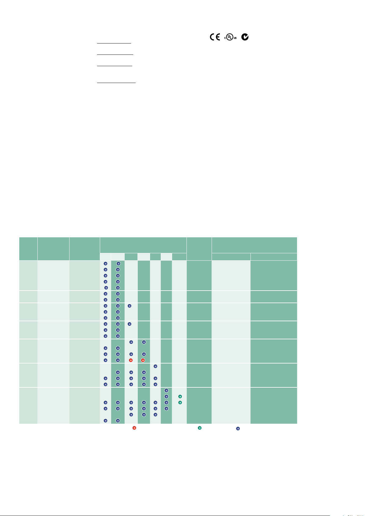
DCS800 Drive Manuals
DCS800 Quick Guide
DCS800 Tools & Documentation CD
DCS800 Converter module
Flyer DCS800 3ADW000190 x x x x x x x
Technical Catalogue DCS800 3ADW000192 x x x x x x x
Hardware Manual DCS800 3ADW000194 x x p x x x x
Hardware Manual DCS800 update DCF503B/DCF504B 3ADW000194Z0301 x
Firmware Manual DCS800 3ADW000193 x x p x p x x
Installation according to EMC 3ADW000032 x
Technical Guide 3ADW000163 x
Service Manual DCS800 3ADW000195 x x
12-Pulse Manual 3ADW000196 x
CMA-2 Board 3ADW000136 p
Flyer Hard - Parallel 3ADW000213 x
Drive Tools
DriveWindow 2.x - User's Manual 3BFE64560981 x
DriveOPC 2.x - User's Manual 3BFE00073846 x
Optical DDCS Communication Link 3AFE63988235 x
DDCS Branching Units - User´s Manual 3BFE64285513 x
DCS800 Applications
PLC Programming with CoDeSys CoDeSys_V23 x x x
61131 DCS800 target +tool description - Application Program 3ADW000199 x
DCS800 Crane Drive
DCS800 Crane Drive Manual suppl. 3AST004143 x
DCS800 Crane Drive Product note PDC5 EN REVA p
DCS800 Winder ITC
DCS800 Winder Product note PDC2 EN x
DCS800 Winder description ITC 3ADW000308 x
Winder Questionnaire 3ADW000253z x
DCS800-E Panel Solution
Flyer DCS800-E Panel solution 3ADW000210 x
Hardware Manual DCS800-E 3ADW000224 x
DCS800-A Enclosed Converters
Flyer DCS800-A 3ADW000213 x
Technical Catalogue DCS800-A 3ADW000198 x
Installation of DCS800-A 3ADW000091 p
DCS800-R Rebuild System
Flyer DCS800-R 3ADW000007 x x
DCS800-R Manual 3ADW000197 x
DCS500/DCS600 Size A5...A7, C2b, C3 and C4 Upgrade Kits 3ADW000256 x
Extension Modules
RAIO-01 Analogue IO Extension 3AFE64484567 x
RDIO-01 Digital IO Extension 3AFE64485733 x
AIMA R-slot extension 3AFE64661442 x
Serial Communication
Drive specific serial communication
NETA Remote diagnostic interface 3AFE64605062 x
Fieldbus Adapter with DC Drives RPBA- (PROFIBUS) 3AFE64504215 x
Fieldbus Adapter with DC Drives RCAN-02 (CANopen)
Fieldbus Adapter with DC Drives RCNA-01 (ControlNet) 3AFE64506005 x
Fieldbus Adapter with DC Drives RDNA- (DeviceNet) 3AFE64504223 x
Fieldbus Adapter with DC Drives RMBA (MODBUS) 3AFE64498851 x
Fieldbus Adapter with DC Drives RETA (Ethernet) 3AFE64539736 x
x -> existing p -> planned
Status 10.2008
DCS800 Drive Manuals-List_h.doc
Public. number E D I ES F CN RU
3ADW000191 x x x x x
3ADW000211 x
Language
4
3ADW000191R0500 DCS800 Quick guide edisf e
Page 5
english
Standard Features
• compact
• highest power ability
• simple operation
• comfortable assistants, e.g. for autotuning or commissioning
• scalable to all applications
• free programmable by means of integrated IEC61131-PLC
3ADW000191R0500 DCS800 Quick guide edisf e
5
Page 6
DCS800 DC Drives
Technical data
Mains supply volt. 230...1,200 V,
+/–10 %, 3~
Frequency 50...60 Hz, +/–5
Hz
Electronics supply 115...230 V,
–15 % / +10 %, 1~
DC Output current 20...5,200 A
Overload capability 200 %
Ambient conditions
Ambient temperat. 0° ... +40° C
40° ... 55°C with
reduction
Storage temperat. –40° ... +55° C
Transport temper. –40° ... +70° C
Relative humidity 5 ... 95 %, not
condensing
(max. 50 % betw.
0°...5° C)
Pollution degree Class 2
Protection class IP 00
Altitude < 1,000 m height
above sea level:
nominal Current
> 1,000 m height
above sea level:
with reduction
I/O
Digital inputs: 8 standard, up to
14 optional
Digital outputs: 8 standard, up
to 12 optional
Analog inputs: 4 standard +/–
10 V; 0/2…10 V, up to 8 optional
+/ 20 mA; 0/4…20 mA
Analog outputs: 3 standard (1x
I
) +/-10 V; 0/2…10 V, up to 7
act
optional –20 mA; 0/4…20 mA
PC-Tools
DriveWindow Light: free of
charge with every converter,
Standard RS232 PC-connection
DriveWindow: Real-time optical
connection
ControlBuilder DCS800:
IEC61131 programming tool
DriveSize: Converter- and motor
dimensioning
Maintenance / Diagnosis
Remote diagnosis with any
Internet-PC worldwide
• with internet browser / internet
explorer
• or with DriveWindow full drive
control via OPC
Approvals
Adaptive Programming
pre-defined drive-specific
function blocks, e.g.
• Free process controller (PIController)
• I/O- and digital Operations
With control panel or PC-Tool, no
need for additional hardware
Speed Feedback
EMF
Analogue tacho
Encoder
2nd Encoder possible (RTAC)
Communication
Serial communication
• Ethernet • Profibus
• CANopen • DeviceNet
• ControlNet • DDCS
• Modbus
• CS31 • AF100
• Selma2
Industrial IT© enabled
DCSLink Peer-to-Peer
• up to 800 kBaud, < 2.5 ms
• Master-Follower
• Armature-fieldconverter
• Free selectable data
High Current Solutions
• 12-pulse up to 20,000 A, serial
and parallel
• Hard parallel and sequential
• up to 1,500 V
Protections
Speed feedback monitoring •
Temperature • Overload • Over
speed • Motor stalled • Motor
over current • Motor over voltage
• Field over current • Field over
voltage • Minimum field current
• Zero speed • Armature current
ripple • Mains over- and under
voltage
Integrated IEC 61131-PLC
• Open standard programming
tool ControlBuilder DCS800
• Support of all five IEC-
languages
• Drive-specific function blocks
• Saving of program and source
in Memory Card
• Online debugging and forcing
Current ratings, dimensions
Unit size 2-Q
rated Current
DCS800-01
IDC[A] IDC[A] 400 525 600 690 800 990 1200 [ADC] h x w x d [mm] h x w x d [inch]
D1 20 25
45 50
65 75
90 100
125 140
D2
180 200
230 260
D3 315 350
405 450
470 520
D4 610 680
740 820
900 1000
D5 900 900 25 1050 x 510 x 410 41.35 x 20.10 x 16.15
1200 1200
1500 1500
2000 2000
D6 1900 1900
2050 2050
2500 2500
3000 3000
D7 2050 2050
2600 2600
3300 3300
4000 4000
4800 4800
5200 5200
4-Q
rated Current
DCS800-02
Supply voltage
[V
]
AC
3)
3)
1)
1)
2)
1)
only available as 2-Q drive
2)
max. field
Dimensions
current
internal
6 370 x 270 x 200 14.56 x 10.65 x 7.90
15 370 x 270 x 270 14.56 x 10.65 x 10.65
20 459 x 270 x 310 18.07 x 10,65 x 12,25
25 644 x 270 x 345 25.35 x 10.65 x 13.60
external field
1750 x 460 x 410 68.90 x 18.15 x 16.15
35A, 1~/3~
50/60A, 1~
520A, 3~
external field
35A, 1~/3~
1750 x 760 x 570 68.90 x 29.95 x 22.45
50/60A, 1~
520A, 3~
2)
on request
3)
600V
2-Q -> 290 A / 590 A
4-Q -> 320 A / 650 A
6
3ADW000191R0500 DCS800 Quick guide edisf e
Page 7

Brief instructions for CD and documents overview
We appreciate that you purchased an ABB DC drive
power converter and thank you for the trust you put in our
products.
This brochure was put together to make sure that you continue
to be satisfied with our product. It is intended to provide you
with a brief overview of the product's key data, EMC notes,
typical applications, start-up and trouble-shooting.
If you need more information about the product you are
provided with a CD-ROM in addition to this brief documen-
tation. The CD-ROM is part of this document and features
the following contents:
System requirements to use the CD-ROM
• Operating system WINDOWS 2000, XP
• ACROBAT READER 4.0 is
sufficient (we recommend
8.0 - included on the CDROM)
In case the CD ROM does not start automatically please
double-click on Setup.exe.
english
Documentation
Our documentation is basically structured according to the
following system:
Technical catalogue (3ADW000192)
as comprehensive information to engineer complete DC
drive systems.
Hardware manual (3ADW000194)
as detailed information, with all important particulars about
the individual components, like module dimensions, electronic
boards, fans and auxiliary components.
Information for mechanical and electrical installation are
also included.
Firmware Manual (3ADW000193)
detailed information with all important issues about firmware
and setting of parameters. The manual includes information
for start-up and maintenance of the entire drive, in detailed
form.
This manual also includes Fault and Alarm codes and information for trouble shooting.
Service Manual (3ADW000195)
for maintenance and repair of the converters.
Further support
In addition we offer further support, since we can only be
satisfied when you, as our customer, are satisfied with us
and our products.
Internet
On the ABB homepage under
www.abb.com/dc
you'll find abundant information for
• DC products
• service support
• the latest updates
• tools
• downloads, etc.
Please don't hesitate to visit us.
Contacts
If you require any further information, please contact your
nearest ABB Drives office or send an email to:
DC-Drives@de.abb.com
Please give us your name, your company address and
phone number. We immediately put you in contact with our
specialist.
Applications
DCS800 DC Drive can include application software e.g.
cranes, winders. In such case following procedures and
assistants can be blocked or not completed. Please check
for further documentation and manuals (check parameter
4.03, 83.01).
Additional information about applications (e.g. 12-pulse)
and technical accessories (e.g. Hardware extension or
Field bus interfaces) are handled by separate manuals. See
table DCS800 Drive manuals.
3ADW000191R0500 DCS800 Quick guide edisf e
7
Page 8
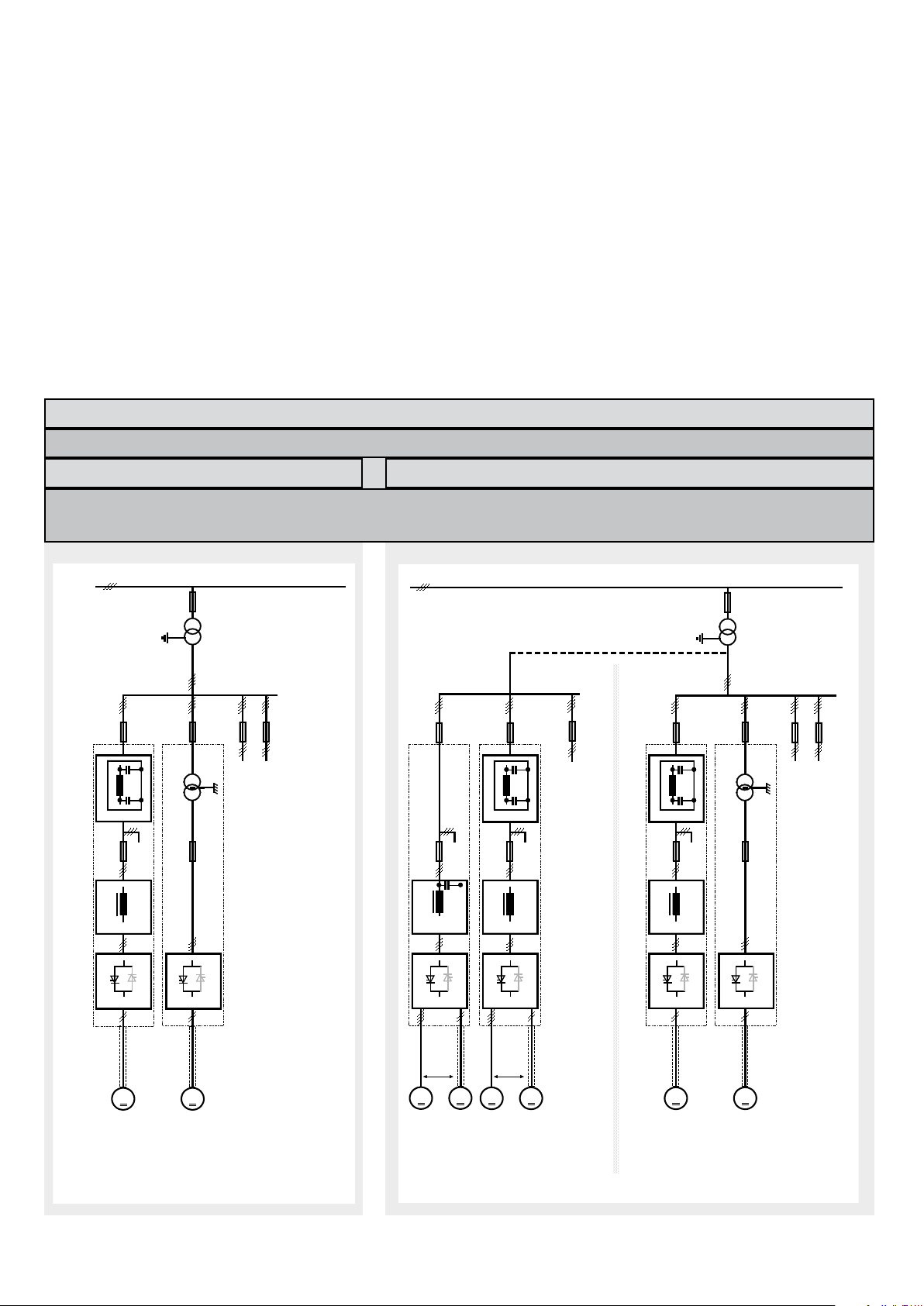
Notes on EMC
MM
Mains filter
Converter
Line reactor
Supply transformer for a residential
area (rating normally ≤ 1,2 MVA)
Earthed public 400-V
network with neutral
conductor
Medium-voltage network
Earthed
neutral
To other loads, e.g. drive systems
An isolating transformer
with an earthed screen
and earthed iron core
renders mains filter and
line reactor superfluous.
Operation at public
low-voltage network
together with other
loads of all kinds.
Residential area
To other loads which have to be protected from the system disturbances caused by
power converters (HF interference and commutation notches)
Converter
MM
MM
MM
alternative
alternative
Line reactor +
Y-capacitor
Medium-voltage network
Supply transformer for a residential
area (rating normally ≤ 1.2 MVA)
Earthed
neutral
Earthed public 400-V
network with neutral
conductor
To other loads, e.g. drive systems
Mains filter
Line reactor
Converter Converter
Mains filter
Line reactor
Converter Converter
An isolating transformer
with an earthed screen
and earthed iron core
renders mains filter and
line reactor superfluous.
Operation at public
low-voltage network
together with other
loads of all kinds.
To other loads, e.g. drive systems
To other loads which have to be protected from the system disturbances caused by
power converters (HF interference and commutation notches)
Earthed public 400-V
network with neutral
conductor
Operation at public
low-voltage network
together with other
loads of all kinds.
Light industry
Residential area
Commutaion notches < 20%
You will find further information in publication:
Technical Guide chapter:
EMC Compliant Installation and Configuration for
a Power Drive System
Not applicable
The paragraphs below describe selection of
the electrical components in conformity with
the EMC Guideline.
The aim of the EMC Guideline is, as the name
The EMC Guideline expects EMC to be taken
into account when a product is being developed;
however, EMC cannot be designed in, it can only
be quantitatively measured.
implies, to achieve electromagnetic compatibility with other products and systems. The
guideline ensures that the emissions from
the product concerned are so low that they
do not impair another product‘s interference
immunity.
In the context of the EMC Guideline, two
Note on EMC conformity
The conformity procedure is the responsibility of
both the power converter‘s supplier and the manu-
facturer of the machine or system concerned, in
proportion to their share in expanding the electrical
equipment involved.
aspects must be borne in mind:
• the product‘s interference immunity
• the product‘s actual emissions
First environment (residential area with light industry) with PDS category C2
Not applied, since category C1 (general distribution sales channel) excluded
satisfied
satisfied
8
3ADW000191R0500 DCS800 Quick guide edisf e
Page 9
For compliance with the protection objectives
MMMM
emv_clssif_b.dsf
Converter
transformer
Case-referenced EMC analysis
alternative
Converter
transformer
with earthed
iron core
(and earthed
screen where
appropriate)
alternative
I > 400 A
and/or
U > 500 V
Operation with separate power converter transformer. If there
are other loads at the same secondary winding, these must be
able to cope with the commutation gaps caused by the power
converter. In some cases, commutating reactors will be
required.
To other loads, e.g. drive systems
Converter Converter
Line reactor
Medium-voltage network
Industrial
zone
MM
MM
MM
I
DC
< 100 A
I
DC
< 100 A
I
DC
>100 A
Supply transformer for a
residential area (rating
normally ≤ 1.2 MVA)
Earthed 400-V network
with neutral conductor
;
3~ ≤ 400 A
Operation at low-voltage network together with
other loads of all kinds, apart from some kinds
of sensitive communication equipment.
To other loads, e.g. drive systems
Line reactor +
Y-capacitor
Line reactor
Converter Converter
Mains filter
Earthed
neutral
Medium-voltage network
Industrial zone
alternative
alternative
Line reactor
Converter
alternative
Commutation notches < 40%
of the German EMC Act (EMVG) in systems and
machines, the following EMC standards must
be satisfied:
Product Standard EN 61800-3
EMC standard for drive systems (PowerDrive-
System), interference immunity and emissions
in residential areas, enterprise zones with light
industry and in industrial facilities.
This standard must be complied with in the EU
for satisfying the EMC requirements for systems
and machines!
Second environment (industry) with PDS categories C3, C4
For emitted interference, the following apply:
EN 61000-6-3 Specialised basic standard for emissions in light industry
can be satisfied with special features (mains filters, screened
power cables) in the lower rating range *(EN 50081-1).
EN 61000-6-4 Specialised basic standard for emissions in industry
*(EN 50081-2)
For interference immunity, the following apply:
EN 61000-6-1 Specialised basic standard for interference immunity in
residential areas *(EN 50082-1)
EN 61000-6-2 Specialised basic standard for interference immunity in in-
dustry. If this standard is satisfied, then the EN 61000-6-1
standard is automatically satisfied as well *(EN 50082-2).
* The generic standards are given in brackets
Standards
EN 61800-3
english
Not applicable
satisfied
on customer's request
satisfied
PDS category C3 PDS category C4
satisfied
EN 61000-6/3
EN 61000-6/3
EN 61000-6-2
EN 61000-6-1
Classification
The following overview utilises the
terminology and indicates the action required in accordance with
Product Standard
EN 61800-3
For the DCS800 series, the limit
values for emitted interference
are complied with, provided the
measure indicated is carried
out. PDS of category C2 (formerly restricted distribution in
first environment) is intended to
be installed and commissioned
only by a professional (person
or organization with necessary
skills in installing and/or commissioning PDS including their
EMC aspects).
For power converters without
additional components, the following warning applies:
This is a product of category C2
under IEC 61800-3:2004. In a
domestic/residential environment
this product may cause radio
interference in which case supplementary mitigation measures
my be required.
The field supply is not depicted
in this overview diagram. For the
field current cables, the same
rules apply as for the armaturecircuit cables.
3ADW000191R0500 DCS800 Quick guide edisf e
9
Page 10
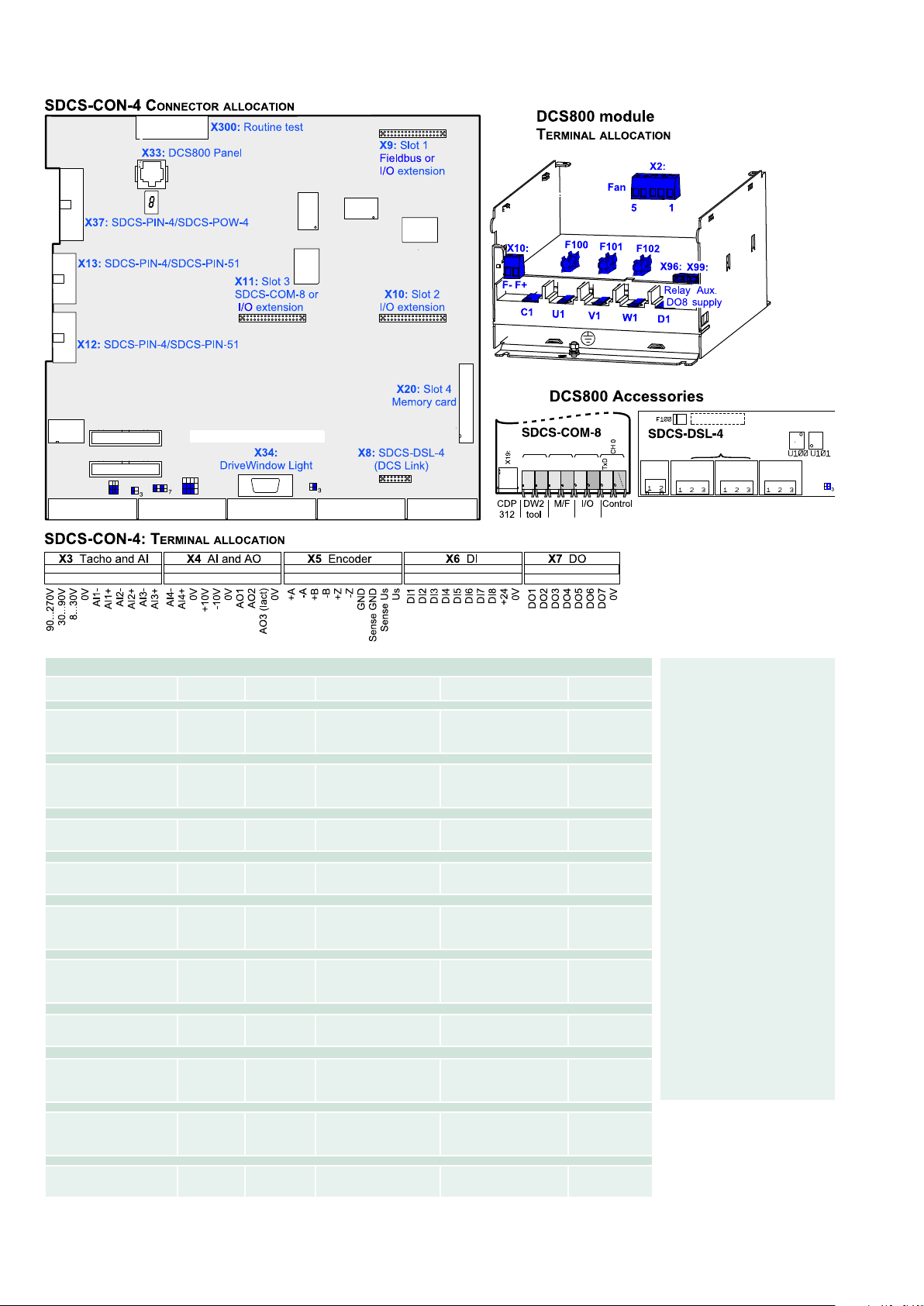
X2:
X1:
ATACH
±90...±270 V
±
30...±90 V
±
8...±30 V
AI4
(5 ms)
GND
GND
39k2
+10V
Power
Sense 0 V
Sense 5 V
AI3
(5 ms)
AI1
(3.3 ms)
+/- I-act
47.5
100
µ
100n
GND (AOx)
+10V
GND
-10V
DI1
DI3
DI4
DO4
DO5
DO1
4k75
3
4
5
6
9
X6:1
3
4
10
4
5
1
2
3
6
5
10
8
9
10
5
2
6
8
10
8
X3:1
X4:1
X5:1
X7:
SDCS-CON-4
Firmware
GND
1
3
S1
Con4_I_O-b.dsf
12k8
5k
1k66
+
-
4
6
S1
S2
3
4
250
S3
56
78
S3
3
4
250
+
-
SDCS-IOB-3
(PS5311)
9
8
7
ATACH1
ATACH2
S1
+
-
+
-
+
-
+
-
GND
1
3
S4
2
121
100nF
4
6
S4
5
121
100nF
7
10
S4
8
121
100nF
10k
10k
10k
+
-
+
-
+
-
PIN-4
= 5 V
S4
11
12
2k21 221k
4k75
47nF
Z15
+
-
5 V
Relay driver
Relay driver
Relay driver
Relay driver
Relay driver
Relay driver
Relay driver
X
9
τ
= 10 ms
τ
= 10 ms
τ
= 10 ms
τ
= 10 ms
τ
= 10 ms
τ
= 3.3 ms
τ
= 3.3 ms
ChA
ChB
ChZ
ChA
ChB
ChZ
POW-4
=
5V/
15V/24V
CON-4
= 24 V
Resolution
[bit]
Encoder supply
Input value
Signal
definition by
Output value
Signal
definition by
Standard function assignments for the terminals
10
3ADW000191R0500 DCS800 Quick guide edisf e
Input/output
values
Hardware
15 + sign ±90...270 V
±30...90 V
ScalingbyCommon
mode
range
①
±15 V
Firmware
Remarks
±8...30 V
15 + sign -10...0...+10 V Firmware ±15 V
15 + sign -10...0...+10 V Firmware ±15 V
15 + sign -10...0...+10 V Firmware ±15 V
15 + sign -10...0...+10 V Firmware ±15V
Power
+10 V ≤ 5 mA
-10 V ≤ 5 mA
for ext. use
e.g. refer. pot.
11 + sign -10...0...+10 V Firmware ≤ 5 mA
11 + sign -10...0...+10 V Firmware ≤ 5 mA
-10...0...+10 V Firmware+
Hardware
≤ 5 mA
8 V -> min. of
325% of [99.03] or
230% of [4.05]
Remarks
Inputs not isolated
Impedance = 120 W, if selected
max. frequence ≤ 300 kHz
5 V
24 V
≤ 250 mA
≤ 250 mA
Sense lines for GND and supply
to correct voltage drops on cable
(only if 5 V encoder is in use).
Remarks
0...7.3 V
7.5...50 V
Firmware
-> “0“ status
-> “1“ status
Remarks
50 * mA
22 V at no
load
Firmware
Current limit for all 7
outputs = 160 mA
Do not apply any reverse
voltages!
* short circuit protected
① gain can be varied in 15 steps between 1 and 4 by software parame-
ter
Page 11
F6
DCS8_ans_1_1d.dsf
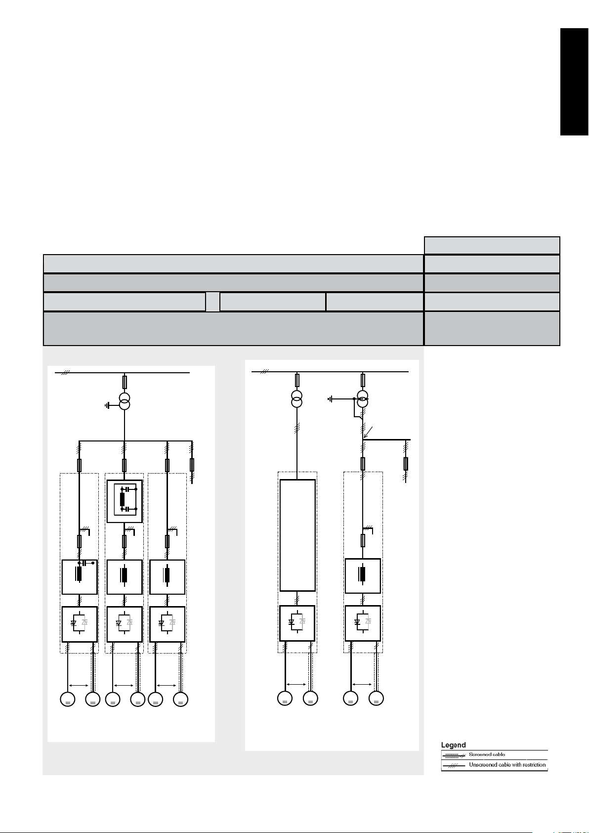
Connection example
Converters D1...D4 drive configuration using ‘OnBoard‘ field exciter
Terminal selection according FACTORY macro (default)
english
3ADW000191R0500 DCS800 Quick guide edisf e
further information see the following page
11
Page 12
ON
RUN
RESET
MCW (7.01)
ON
RUN
RESET
ON
RUN
RESET
7.04
gen_ctrl_cmd_a.dsf
USED MCW
HW I/O
command
location (10.01)
PC tool or panel
local /
remote
used
Main Control Word
START, STOP and E-STOP control
K16
K15 K16
K15
DI4
K15
X6:9
CON-4
S1
1
2
Anschl_special_a.dsf
EMER.
STOP
ELEC.
DISCONN.
Block
current
command
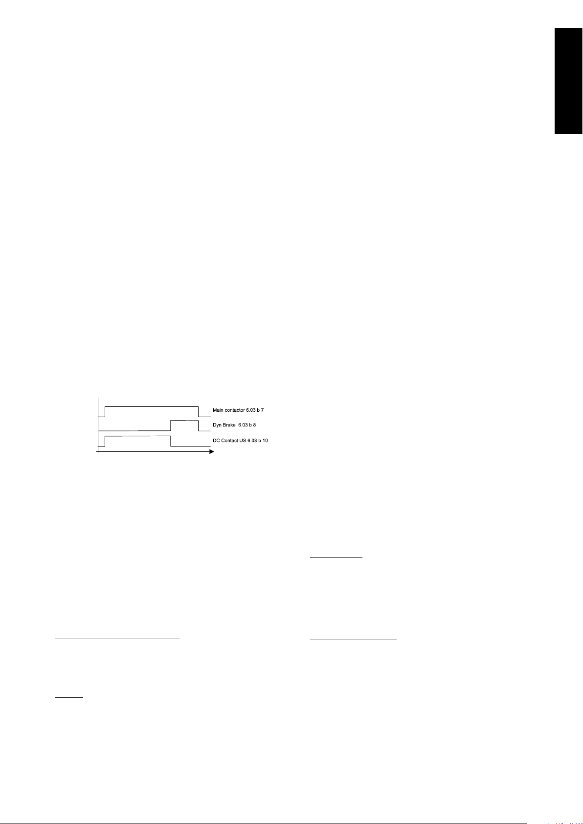
Timer K15
Timer K16
Stop-Mode_a.dsf
E-STOP
speed
Block current control
K1 main contactor
E-Stop ramp Coast
The relay logic can be split into three parts:
a: Generation of the ON/OFF and START/STOP com-
mand:
The commands represented by K20 and K21 (latching interface relay) can be e.g. generated by a PLC and transferred to
the terminals of the converter either by relays, using galvanic
isolation or directly via 24V signals.
These commands can be as well transferred via serial
communication. Even a mixed solution can be realized by
selecting different possibilities for the one or the other signal
(see parameter group 11).
b: Generation of control and monitoring signals:
The main contactor K1 for the armature circuit is controlled
by a dry contact (DO 8) located on the SDCS-PIN-4. Status
of fans and fans klixon can be monitored by means of fan
ack signals: MotFanAck (10.06) and ConvFanAck (10.20).
If the drive has not finished the function within the K15 timer
setting, the drive must get the command to switch OFF the
current via K16. After K16 timer set has elapsed the main
contactor is opened independent of the drives status.
c: OFF2, OFF3 Stop function:
Beside ON/OFF and START/STOP, the drive is equipped
with two additional stop functions, OFF2 and OFF3, according to Profibus standard. OFF3 is a scalable stop function
(rampstop, max torque stop, dynamic braking …) to perform
stop category 1. This function should be connected to the
E-STOP button without any time delay. In case of ramp stop
selection the, K 15 timer relay must be set longer than the
EStopRamp (22.04). For COAST selection, the drive opens
the main contactor immediately.
OFF2 switches off DC current as fast as possible and prepares the drive for opening main contactor or drop down
mains supply. For a normal DC motor load the time to switch
OFF the DC current is below 20 ms. This function should be
connected to all signals and safety functions opening the main
contactor. This function is important for 4-quadrant drives.
Do not open main contactor during regenerative current.
The correct sequence is
1. switch off regenerative current
2. then open the main contactor
In case of the E-STOP is hit, the information is transferred
to the converter via digital input 5. In case of rampstop, or
max torque selection the converter will decelerate the motor
and then open main contactor.
12
3ADW000191R0500 DCS800 Quick guide edisf e
E-Stop reaction
Page 13
Fan power connection
1 2 3
X2:
4 5
L
N
230 Vac
1 2 3
X2:
4 5
L
N
115 Vac
M
~
1 2 3
X2:
M
~
4 5
M55 M56
M
~
1 2 3
X2:
M
~
4 5
M55 M56
M
~
M
~
M57 M58
M55
M
~
1 2 3 4 5
X2:
L
N
L
N
1 2 3
X2:
4 5
L
N
230 Vac
1 2 3
X2:
4 5
L
N
115 Vac
ϑ
230 VAC
or
115 VAC with Pluscode +S171
DCS8 fan conn D1-D4.dsf
Fan assignment for DCS800
Converter type Model Configuration Fan voltage
DCS800-S01-0020-04/05...
DCS800-S02-0025-04/05
DCS800-S0x-0045-04/05...
DCS800-S0x-0140-04/05
DCS800-S0x-0180-04/05...
DCS800-S0x-0260-04/05
DCS800-S0x-0315-04/05...
DCS800-S0x-0350-04/05
DCS800-S0x-0405-04/05...
DCS800-S0x-0520-04/05
DCS800-S0x-0610-04/05...
DCS800-S0x-0820-04/05
DCS800-S0x-0610-04/05...
DCS800-S0x-0820-04/05
Pluscode S171
DCS800-S0x-0900-04/05...
DCS800-S0x-1000-04/05
DCS800-S0x-0900-04/05...
DCS800-S0x-1000-04/05
Pluscode S171
Fan connection for DCS800
Terminals on top of converter housing
D1 - no fan
D1 1 115 or 230 VAC
D2 1 115 or 230 VAC
D3 1 115 or 230 VAC
D3 2 115 or 230 VAC
D4 3 230 VAC
D4
3 115 VAC
D4 3 230 VAC
D4
3 115 VAC
english
Configuration 1
D1- D3
Configuration 2
D3
3ADW000191R0500 DCS800 Quick guide edisf e
Configuration 3
D4
13
Page 14
DCS800 terminal alloc.dsf
X4X3 X5 X6 X7
1 1 1 1 1
2
S5
1
15
6 9
S3
S2
1
X1
X2
X17
2
25
26
1
2
25
26
S4
1
2
1
2
1
2
1
2
H2500
1
2
D2100
1
D2001
D2001
D1000
1 30
1
2
1
2
1
2
1
26
S1
1
42
1
2
3
10
11
12
1
82
1
42
1
2
3
7
8
9
Jumpers shown in default position
1 2 3 4 5 6 7 8 9 10 1 2 3 4 5 6 7 8 9 10 1 2 3 4 5 6 7 8 9 10 1 2 3 4 5 6 7 8 9 10 1 2 3 4 5 6 7 8
X8
1
42
S2
S1
1
2
3
X51 X52 X53 X54
24V
DCS Link
24V
0V
GND B
CANL
CANH
GND B
CANL
CANH
grey
grey
grey
grey
dark
grey
dark
grey
d
ark
grey
blue
blue
RxD
CH 1
TxD
RxD
CH 2
TxD
RxD
CH 3
TxD
RxD
Terminal locations on the converter
Macro finder
DI function
Jog1 --> DI1
Jog2 --> DI2
Ext Fault --> DI 3
Ext Alarm --> DI4
Jog1 --> DI1
Jog2 --> DI2
Ext Fault --> DI 3
Main Cont Ack --> DI4
Fix speed1 --> DI1
Ext Fault --> DI 3
Main Cont Ack --> DI4
Fix speed1 --> DI1
Ext Fault --> DI 3
Ext Alarm --> DI4
Jog1 --> DI1
Jog2 --> DI2
Ext Fault --> DI 3
Ext Alarm --> DI4
Jog1 --> DI1
Jog2 --> DI2
Direction --> DI 3
SpC - KP, KI --> DI4
Control select --> DI2
Reference select --> DI2
Direction select --> DI 3
Motor pot up --> DI1
Motor pot down --> DI2
Direction select --> DI 3
Reference select --> DI4
Direction select --> DI 1
Motor pot up --> DI2
Motor pot down --> DI3
Motor pot minimum --> DI4
OFF2 (coast stop) --> DI1
Torque select --> DI2
Ext Fault --> DI 3
Standard
Macro name
Main
Contactor
ON / OFF
Start/Stop
AC Static
2-wire DC cont. US
DC Static
3-wire DC cont. US
DC Pulse
3-wire Standard
Torque limit
Manual / Const
AC Pulse
AC Static
AC Pulse
Hand / Auto
AC Static
Hand / Mot Pot
AC Pulse
AC Static
AC Static
Motor Pot
Torque Ctrl
Comment DI5 --> ESTOP
Hardware I/O control x
Hardware I/O control x
Hardware I/O control x
Hardware I/O control x
Hardware I/O control
+ Torque limit
Hardware I/O control
select gain
Hardware I/O control
or field bus control
Hardware I/O control
Reference hardware or Motor
potentiometer
Hardware I/O control
Reference Motor potentiometer
Hardware I/O control
Speed control or Torque
reference
DI6 --> Reset
x
x
x
x
x
x
Enabling a macro
Use the
[DCS800Wizard] 2. Macro
assistant of DriveWindow
Light or
Parameter browser, either
through the control panel,
DriveWindow, or DriveWindow
Light.
Use the following parameters:
ApplMacro (99.08) =
Macro selection
Applrestore (99.07) =
YES = execute selection
MacroSel (8.10) =
double check
NOTE
Functions and inputs defined
by macro can be changed later on without restrictions.
NOTE
Macro diagrams see page
93 ...
14
3ADW000191R0500 DCS800 Quick guide edisf e
Page 15
Notes For North American Installations
1. EMC conformity is not usually required in North America. In most cases, the section “Notes on EMC” can be
bypassed. In this manual, you will see references to DIN, EN
and VDE standards. These are European standards and,
generally, do not apply to North America. It is, however,
the responsibility of the user to determine which standards
need to be followed.
2. If using a DC contactor, you must connect an auxiliary
contact to a digital input of your choice and set para. Main-
ContAck accordingly. Set the following parameters:
MainContAck (10.21) = DI-1 (or any input you
choose for the DC cont.
auxiliary contact)
DO8BitNo (14.16) = 10
MainContCtrlMode (21.16) = DCcontact (3)
Set these parameters AFTER macros are loaded but BEFORE
the drive is commissioned.
Digital output 8 (DO-8) must be used to turn the DC
contactor on and off.
DC contactor US:
DC contactor US K1.1 is a special designed contactor with 2x
NO contacts for C1 and D1 connection and 1x NC contact for
connection of Dynamic Brake resistor RB.
The contactor should be controlled by signal 6.03 Bit 10.
The acknowledge can be connected to parameter:
10.21 MainContAck
10.23 DCBreakAck
3. If using Dynamic Braking, the drive allows you to select the stopping method under three different situations.
Parameters 21.02, 21.03 and 21.04 select the stopping
method for loss of
the OnOff, run command (StartStop, Jog1, Jog2, etc.), and
E-Stop input, respectively.
Each can be set to:
• RampStop • TorqueLimit
• CoastStop • DynBraking
In order to command the drive to perform a DB stop, one
or more of these parameters must be set to DynBraking.
Most users will want the drive to ramp stop when OnOff or a
run command (StartStop, Jog1, Jog2, etc.) input is cleared,
and dynamically brake when the E-Stop input is cleared. In
that case, use the following settings:
• Off1Mode (21.02) = RampStop
• StopMode (21.03) = RampStop
• E StopMode (21.04) = DynBraking
However, any case is allowed and the final decision is left
to the user.
Other parameters control stops during faults.
See:
LocalLossCtrl (30.27) ComLossCtrl (30.28)
FaultStopMode (30.30) SpeedFbFltMode (30.36)
If using EMF feedback with dynamic braking, set:
• DynBrakeDly (50.11) = t
Where: t = the time (sec) it normally takes the motor
to stop during dynamic braking
english
Overview of the Installation and Commissioning Process
Step 1:
Check converter for damage. Contact ABB Technical Support
if damage is found. In North America, call 1-800-435-7365
(1-800-HELP-365)
Step 2:
Select supporting hardware for the converter:
For specific recommendations for fuses, reactors, and
contactors, see the DCS800 hardware manual or technical
catalog.
Circuit breaker or disconnect:
Current rating = Idc * 0.816 * 1.25 (min)
= Idc * 0.816 * 2.50 (max)
Where: Idc = nominal DC motor current
Fuses:
AC Line Fuses: To properly protect the converter, semiconductor fuses on the incoming AC power line are required
in all cases.
DC Output Fuses: Fuses between the motor and the
converter are required for all regenerative (4-Q) converters.
This is to protect the motor and converter if a commutation
fault should occur. NOTE: DC output fuses are the same
type and size as AC line fuses.
Line reactor:
All thyristor-based dc converters cause notching in the AC
line due to motor commutation. A properly sized line reactor
will mitigate the effect on the line. Unless the converter uses
a dedicated isolation transformer, each converter requires
its own line reactor.
AC or DC contactor:
A contactor is required to safely disconnect the motor from
the incoming power when the converter is off. The contactor
can be installed between the line and the converter (an AC
contactor) or between the converter and the motor (a DC
contactor). Do not use both.
IMPORTANT: Other equipment may be necessary depending on application and local codes.
3ADW000191R0500 DCS800 Quick guide edisf e
15
Page 16

Step 3:
Mount and wire the converter and supporting hardware inside an industrial enclosure with adequate cooling (DCS800
modules have rating of NEMA type OPEN).
The following control and signal wiring is required:
o If using an AC contactor, we recommend wiring an auxi-
liary contact to the digital input you have designated as
MainContAck (10.21) or Start/Stop (10.16).
o If using a DC contactor, you must wire an auxiliary contact
from the contactor to the digital input you have designated
as MainContAck (10.21).
o Wire 115 or 230 Vac 1-phase power to terminal block 99
for converter control power.
o Wire 1-phase power to converter for cooling fans. See
table and wiring diagrams in this manual.
• D1 – D3 frames: 115/230 Vac selectable. Fan
terminal X2 is on top of the converter.
• D4 frame: If type code includes +S171, use 115
Vac; otherwise use 230 Vac. Fan terminal X2 is
on top of the converter.
o Wire tachometer or encoder to terminal block X3 (tacho)
or X5 (encoder).
o Wire analog inputs (e.g., speed reference) and outputs
(e.g., meters for motor voltage, current) to terminal block
X3 and/or X4.
o Wire high speed serial interface if needed. (Requires
optional fieldbus interface board.)
o The DCS800 allows you to choose the usage of each
digital and analog input and output. The converter has
factory default settings which can be changed by loading
a macro, but some designations are universal. They
include:
• Digital input 5: Estop
• Digital input 6: Fault reset
• Digital input 7: On/Off (maintained) or On-Start
(pulsed)
• *Digital input 8: Start/Stop (maintained) or Off-
Stop (pulsed)
• Digital output 8: Main Contactor On (3 Amps
max. at 115 – 230 Vac)
*except Hand/Auto macro
o Other signals may be required depending on your ap-
plication (e.g., motor fan acknowledge input, Off2 input,
fan-on output, brake output).
o You will select the macro and / or choose the configuration
for digital and analog inputs and outputs in step 2 of the
commissioning process, or by updating group 10 and 14
parameters.
o Check all wire terminations (with continuity tester) before
proceeding to the next step.
Step 4:
Connect the drive system to incoming power and the motor to
the converter (both field and armature) as well as accessory
equipment (motor fan, thermal switch, brake, etc.).
o See hardware manual for typical cable size and tightening
torque recommendations.
o IMPORTANT: Be sure all safety equipment is properly
sized for your application
Step 5:
Apply control power to the converter.
o IMPORTANT: See section “Safety and Operating
Instructions” in this manual before proceeding.
o Apply power to terminal block 99 and X2. The keypad
should light up and show the menu screen. The converter
fans should start to run (if converter has fans).
Step 6:
Commission the converter using Drive Windows Light
(preferred) or the control panel.
o IMPORTANT: See safety alerts and general instructions
in the section “Commissioning” before proceeding.
o Install the DCS800 PC tools on your computer. Instructions
are in this manual. Use DriveWindow Light to commission
your converter.
o If no PC is available, commission your drive using the
control panel as follows:
• On the control panel, press the softkey to select
MENU.
• Using the down arrow, select ASSISTANTS. Then
press ENTER.
• Starting with “name plate data,” press SEL.
Change the value with the arrow keys. Then press
SAVE.
• Repeat above with other parameters. Follow
directions on the screen.
Configuring and Displaying analog and digital I/O
HINT: To see if the drive is responding to an “on” or “run” command, view signal 8.08.
Control Panel:
o Digital Status: View signal 8.05 (DI’s) or 8.06 (DO’s).
Display is in hexadecimal.
o Configure digital inputs with Group 10.
o Analog Status: View signal 5.03 (AI1) or 5.11 (AO1).
Display is in Volts.
o Configure analog speed ref. with Group 11.
DriveWindow Light:
o Connect to the DCS800 and go on line by clicking on
File, then New Online Drive.
o Click on Wizard, at left side of the screen.
o Click on Advanced.
o Check the box for “I/O assistant,” then click on Next.
o Click on “edit parameters” in the appropriate section
(analog or digital inputs or outputs).
16
3ADW000191R0500 DCS800 Quick guide edisf e
Page 17

Safety and operating instructions
for drive converters DCS / DCF / DCR
(in conformity with the low-voltage directive 73/23/EEC)
1. General
In operation, drive converters, depending on their degree of
protection, may have live, uninsulated, and possibly also moving
or rotating parts, as well as hot surfaces.
In case of inadmissible removal of the required covers, of
improper use, wrong installation or maloperation, there is the
danger of serious personal injury and damage to property.
For further information, see documentation.
All operations serving transport, installation and commissioning
as well as maintenance are to be carried out by skilled technical personnel (Observe IEC 364 or CENELEC HD 384 or DIN
VDE 0100 and IEC 664 or DIN/VDE 0110 and national accident
prevention rules!).
For the purposes of these basic safety instructions, “skilled
technical personnel” means persons who are familiar with the
installation, mounting, commissioning and operation of the
product and have the qualifications needed for the performance
of their functions.
english
4. Installation
The installation and cooling of the appliances shall be in accordance with the specifications in the pertinent documentation.
The drive converters shall be protected against excessive
strains. In particular, no components must be bent or isolating
distances altered in the course of transportation or handling. No
contact shall be made with electronic components and contacts.
Drive converters contain electrostatic sensitive components
which are liable to damage through improper use. Electric
components must not be mechanically damaged or destroyed
(potential health risks).
5. Electrical connection
When working on live drive converters, the applicable national
accident prevention rules (e.g. VBG 4) must be complied with.
The electrical installation shall be carried out in accordance with
the relevant requirements (e.g. cross-sectional areas of conductors, fusing, PE connection). For further information, see documentation.
2. Intended use
Drive converters are components designed for inclusion in electrical installations or machinery.
In case of installation in machinery, commissioning of the drive
converter (i.e. the starting of normal operation) is prohibited until
the machinery has been proved to conform to the provisions of
the directive 89/392/EEC (Machinery Safety Directive - MSD).
Account is to be taken of EN 60204.
Commissioning (i.e. the starting of normal opertion) is admissible
only where conformity with the EMC directive (89/336/EEC) has
been established.
The drive converters meet the requirements of the low-voltage
directive 73/23/EEC. They are subject to the harmonized standards of the series prEN 50178/DIN VDE 0160 in conjunction with
EN 60439-1/ VDE 0660, part 500, and EN 60146/ VDE 0558.
The technical data as well as information concerning the supply conditions shall be taken from the rating plate and from the
documentation and shall be strictly observed.
3. Transport, storage
The instructions for transport, storage and proper use shall be
complied with.
Instructions for the installation in accordance with EMC requirements, like screening, earthing, location of filters and wiring,
are contained in the drive converter documentation. They must
always be complied with, also for drive converters bearing a
CE marking. Observance of the limit values required by EMC
law is the responsibility of the manufacturer of the installation or
machine.
6. Operation
Installations which include drive converters shall be equipped
with additional control and protective devices in accordance with
the relevant applicable safety requirements, e.g. Act respecting
technical equipment, accident prevention rules etc. Changes
to the drive converters by means of the operating software are
admissible.
After disconnection of the drive converter from the voltage
supply, live appliance parts and power terminals must not be
touched immediately because of possibly energized capacitors.
In this respect, the corresponding signs and markings on the
drive converter must be respected.
During operation, all covers and doors shall be kept closed.
7. Maintenance and servicing
The manufacturer’s documentation shall be followed.
The climatic conditions shall be in conformity with prEN 50178.
Keep safety instructions in a safe place!
3ADW000191R0500 DCS800 Quick guide edisf e
17
Page 18

Installing the DCS800 PC tools on Your computer
After inserting the DCS800 CD all programs and documentation
necessary to work with the DCS800 will be automatically installed.
This includes:
1. DriveWindow Light for parameterization, commissioning and
service
2. Hitachi FDT 2.2 for firmware download
3. Installation CD of DCS800 Drive for e.g. DWL Wizard, ABB
documents
4. CoDeSys for 61131 application programming
Attention:
If You do not want to install a certain program just skip it by using
Cancel at the beginning of the program’s wizard.
If the installation routine does not start automatically:
- Go to Start/Run and browse for setup.exe on the CD. Now start
the installation by confirming with OK
- Compact installtion for DriveWindow Light + Commsioning
Wizard + DriveWindow Light AP is reccomended
• Start DriveWindow Light PC tool
Check the communication setting of your COM port
If You use USB to COM port interface or PCMCIA / COM ad-
apters double check the active COM enabled
Start => Settings => Control Panel =>
System => Hardware
=> Device Manager
Steps to connect Drive to PC
• The documentation can be found under
C:\ABB\DCS800\Docu
• Remove design cover from the converter module
Remove the DCS800 Control Panel if Connect drive (X34) to your PC COM port
present. Depress the locks to remove
the cover
18
3ADW000191R0500 DCS800 Quick guide edisf e
COM address of USB interface can change after the next boot
procedure or after disconnecting and reconnecting of the USB
interface.
Note:
PCMCIA to COM Port provide a stable and faster drive interface.
Utilize DriveWindow Light or DCS800 Panel Wizard continue
with chapter Commissioning in this manual.
For commissioning by DriveWindow find a workspace description in the DCS800 Firmware manual.
Page 19

Commissioning
7. Field weakening assistant
6. Autotuning speed cont roller
5. Speed feedback assistant
4. Autotuning armature current controller
3. Autotuning field current controller
2. Macro assistant
1. Name plate data
Next >
Next >
Next >
Next >
Next >
Next >
Select specific
assistant & press Next
Wiz select.dsf
Danger! High voltage: this symbol warns of high
voltages which may result in injuries to persons
and/or damage to equipment. Where appropriate,
the text printed adjacent to this symbol describes
how risk of this kind may be avoided.
General warning: this symbol warns of non-electrical risks and dangers which may result in serious
or even fatal injuries to persons and/or damage to
equipment. Where appropriate, the text printed
adjacent to this symbol describes how risk of this
kind may be avoided.
Warning of electrostatic discharge: this symbol
warns you against electrostatic discharges which
may damage to unit. Where appropriate, the text
printed adjacent to this symbol describes how risk
of this kind may be avoided.
NEC motor overload protection
The DCS800 provides a solid-state motor overload
protection in accordance with the NEC. The overload
protection (e.g. protection level in percent of full-load
motor current) can be adjusted by parameters in
group 31 and group 99.
The instructions can be found in chapter Motor
thermal model of the DCS800 Firmware manual.
General instructions
• This short commissioning refers to Chapter 5 Connection examples of this publication.
• Safety and operating instructions - see chapter 6
of this publication.
• Recommendations for motor and field voltages see
Technical catalogue.
• In accordance with DIN 57 100 Part 727 / VDE 0100
Part 727, precautions must be taken to enable the
drive to be shut down, e.g. in the event of danger.
The unit’s digital inputs or the control panel are not
sufficient as the sole measure for this purpose!
Preparations
• Check unit for any damage!
• Install unit and wire it up
• Supply voltage level / Rated value correct for electronics and fan?
• Supply voltage level / Rated value correct for armature-circuit converter?
• Supply voltage level / Rated value correct for field
supply?
• Wiring / cross-sections, etc. correct?
• EMERGENCY STOP functioning properly?
• COAST STOP functioning properly?
english
Commissioning DriveWindow Light
Start the wizard in DriveWindow Light:
For basic commissioning press the Start button or select a specific assistant:
For more information about the wizard, parameters faults and alarms press the Help
button!
3ADW000191R0500 DCS800 Quick guide edisf e
19
Page 20

DCS800 Control Panel
DCS800 QG pan ov_a.dsf
The following table summarizes the button functions and displays of the
DCS800 Control Panel (DCS CP).
With USISel (16.09) it is possible to limit the amount of displayed parameters!
General display features
Following modes are available in the MAIN MENU:
1. Parameters mode
2. Start-up assistants mode
a. Name plate data
b. Macro assistant
c. Autotuning field current controller
d. Autotuning armature current controller
e. Speed feedback assistant
(Tacho fine tuning not available)
f. Autotuning speed controller
g. Field weakening assistant
(only used when maximum speed is higher than
base speed)
3. Macros mode (currently not used)
4. Changed parameters mode (compare to default and
display changed parameters)
5. Fault logger mode (Display fault history)
6. Clock set mode
7. Parameter backup mode
• copy active parameter set from the drive into the
DCS800 Control Panel (only in local mode)
• copy parameter set from DCS800 Control Panel into
the drive (only in local mode)
8. I/O settings mode (currently not used)
Parameters entered by assistant
99.02 Motor 1 nominal Voltage
99.03 Motor 1 nominal current
99.04 Motor 1 base speed
20.01
20.02
99.11 Motor 1 nominal field current
30.09 Armature over current level
30.16 Motor 1 over speed
99.10 Nominal mains voltage
99.12
20.05
20.06
20.12
20.13 Motor 1 current limit bridge 2
50.04 Motor 1 encoder pulse number, if selected
50.02
50.13 Motor 1 tacho volt, only DWL
50.12
20.03
22.01
22.02
30.12
44.01 Field control mode
Motor 1 minimum speed
Motor 1 maximum speed
Motor 1 used fex type
Torque maximum
Torque minimum
Motor 1 current limit bridge 1
Motor 1 encoder measured mode, if selected
Motor 1 tacho adapt, only DWL
Zero speed limit
Acceleration time 1
Deceleration time 1
Motor 1 field minimum trip
20
3ADW000191R0500 DCS800 Quick guide edisf e
Page 21

Dimensions, drilling patterns and weights — Abmessungen, Bohrbild und
S = 5 mm
S = 10 mm
S
S
H
A
B
A B C D E F G H
4x45=180
86
32.5
45
64.5
C1 U1 V1 W1 D1
10
270
225
48.5
for size D1
for size D2...D3
direction of air flow
screw M6
fan terminal
earthing
point
screw
Size Weight
D1toD3_dim_b.dsf
E
F
G
10.5
T2
T1
C
D
43.5
8.7
9
20
Power connection
Field and power
supply terminals
Signal terminals
Mounting direction
310 for size D1/D2
400 for size D3
Minimum
Bottom clearance
T2 = 100mm for size D1
T2 = 150mm for size D2/D3
Minimum
Top clearance
T1 = 150mm for size D1
T1 = 250mm for size D2/D3
Gewichte — Dimensioni, schemi di foratura e pesi — Dimensiones, patrones
de taladrado y pesos — Dimensions, perçages et poids
Module D1
DCS800-S01-0020
DCS800-S01-0045
DCS800-S01-0065
DCS800-S01-0090
DCS800-S01-0125
DCS800-S02-0025
DCS800-S02-0050
DCS800-S02-0075
DCS800-S02-0100
DCS800-S02-0140
Module D2
DCS800-S01-0180
DCS800-S01-0230
DCS800-S02-0200
DCS800-S02-0260
Module D3
DCS800-S01-0315
DCS800-S01-0405
DCS800-S01-0470
DCS800-S02-0350
DCS800-S02-0450
DCS800-S02-0520
600 V types
DCS800-S01-0290
DCS800-S02-0320
Dimensions in mm
Maße in mm
Dimensioni in mm
1
Dimensiones en mm
Dimensions en mm
Installation direction
1
Air direction
Montagerichtung
Luftrichtung
Direzione di installazione
Direzione aria
Modo de instalación
Dirección del aire
Sens de montage
Sens de circulation de
l‘air
Data for converters with
more than 1000 A (D5)
see Hardware manual
Daten für Stromrichter
mit mehr als 1000 A
(D5) siehe Hardware
Handbuch
Dati per convertitori di
potenza da oltre 1000
A (D5), si veda Hardware
manual
Datos para convertidores de más de 1.000 A
(D5), véase
Hardware manual
1
Données pour variateurs
supérieurs à 1000 A (D5),
cf. Manuel d’installation
3ADW000191R0500 DCS800 Quick guide edisf e
77
Page 22

Module D4
D4_dim_b.dsf
345
298
8.7
250
577
150
9
287.5(CON-4)
240(PIN-4)
195.5
147.5
25
20
42
fan terminal
min. Top clearance
min. Bottom clearance
Earthing
M12
Direction of air flow
S = 10 mm
S S
f. M6
48.5
270
225
644
625
107
52
40
80
80
80
f. M12
45
U1
V1
W1
C1
D1
for size D4
fan terminal
Power terminal: Busbar 40x5 mm
Weight appr. 38 kg
DCS800-S01-0610
DCS800-S01-0740
DCS800-S01-0900
DCS800-S02-0680
DCS800-S02-0820
DCS800-S02-1000
600 V types
DCS800-S01-0590
DCS800-S02-0650
Weight appr. 38 kg
1
Installation direction
1
Air direction
Montagerichtung
Luftrichtung
Direzione di installazione
Direzione aria
Modo de instalación
Dirección del aire
Sens de montage
Sens de circulation de
l‘air
Data for converters with
more than 1000 A (D5)
see Hardware manual
Daten für Stromrichter
mit mehr als 1000 A
(D5) siehe Hardware
Handbuch
Dati per convertitori di
potenza da oltre 1000
A (D5), si veda Hardware
manual
Datos para convertidores de más de 1.000 A
(D5), véase
Hardware manual
Données pour variateurs
supérieurs à 1000 A (D5),
cf. Manuel d’installation
78
3ADW000191R0500 DCS800 Quick guide edisf e
Page 23

Texto en el DCS800 Panel,
Texte dans la DCS800
Testo DCS800 Pannello,
FR
Description
DriveWindow
Microconsole,
DriveWindow Light et
AuxUnderVolt
Défaut tension auxiliaire
ArmOverCur
Surintensité, ArmOvrCurLev (30.09)
ArmOverVolt
Surtension d’induit (circuit c.c.),
ArmOvrVoltLev (30.08)
ConvOverTemp
Echauffement anormal du pont de
puissance, MaxBridgeTemp (4.17)
ResCurDetect
Défaut de terre (Σ I différent de
zéro), ResCurDetectSel (30.05)
M1OverTemp
Moteur 1 echauffement anormal,
M1FaultLimTemp (31.07)
M1OverLoad
Moteur 1 surcharge,
M1FaultLimLoad (31.04)
I/OBoardLoss
____________________________
M2OverTemp
Moteur 2 echauffement anormal,
M2FaultLimTemp (49.37)
M2OverLoad
Moteur 2 surcharge,
M2FaultLimLoad (49.34)
ConvFanCur
Courant du ventilateur du
convertisseur hors limites,
ConvTempDly (97.05)
MainsLowVolt
Sous-tension réseau (c.a.) ,
UnetMin1 (30.22)
SP
Definición
DriveWindow
DriveWindow Light y
AuxUnderVolt
Fallo de tensión auxiliar
(Subtensión auxil.)
ArmOverCur
Sobrecorriente (Sobreintensidad),
ArmOvrCurLev (30.09)
ArmOverVolt
Sobretensión de inducido (circuito
de C.C.), ArmOvrVoltLev (30.08)
ConvOverTemp
Sobretemperatura en la sección
de potencia, MaxBridgeTemp (4.17)
ResCurDetect
Fallo a tierra (Σ I distinto a cero),
ResCurDetectSel (30.05)
M1OverTemp
Motor 1 sobretemperatura,
M1FaultLimTemp (31.07)
M1OverLoad
Motor 1 sobrecarga,
M1FaultLimLoad (31.04)
I/OBoardLoss
Tarjetas E/S no encontradas o
faltan, comprobar parámetros gr.
94 y 98.________
M2OverTemp
Motor 2 sobretemperatura,
M2FaultLimTemp (49.37)
M2OverLoad
Motor 2 sobrecarga,
M2FaultLimLoad (49.34)
ConvFanCur
Intensidad en ventilador del
convertidor fuera de los límites,
ConvTempDly (97.05)
MainsLowVolt
Tensión Baja de red (C.A.),
UnetMin1 (30.22)
IT
Descrizione
DriveWindow
DriveWindow Light e
AuxUnderVolt
Guasto tensione ausiliaria
ArmOverCur
Sovracorrente, ArmOvrCurLev
(30.09)
ArmOverVolt
Sovratensione d’indotto (circuito in
c.c.), ArmOvrVoltLev (30.08)
ConvOverTemp
Sovratemperatura sezione di
potenza, MaxBridgeTemp (4.17)
ResCurDetect
Guasto a terra (Σ I diverso da zero),
ResCurDetectSel (30.05)
M1OverTemp
Motore 1 sovratemperatura,
M1FaultLimTemp (31.07)
M1OverLoad
Motore 1 sovraccarico,
M1FaultLimLoad (31.04)
I/OBoardLoss
______________________
M2OverTemp
Motore 2 sovratemperatura,
M2FaultLimTemp (49.37)
M2OverLoad
Motore 2 sovraccarico,
M2FaultLimLoad (49.34)
ConvFanCur
La corrente del ventilatore del
convertitore non rientra nei limiti,
ConvTempDly (97.05)
MainsLowVolt
Minima tensione di alimentazione
di rete (c.a.), UnetMin1 (30.22)
D
DriveWindow
Beschreibung
DriveWindow Light und
Text in DCS800 Panel,
AuxUnderVolt
Hilfs-Unterspannung, Klemme X99
auf SDCS-PIN-4 und SDCS-POW-4
ArmOverCur
Überstrom Anker, ArmOvrCurLev
(30.09)
ArmOverVolt
Überspannung Gleichstromkreis
(DC), ArmOvrVoltLev (30.08)
EN
Definition
DriveWindow
DriveWindow Light and
Text on DCS800 panel,
AuxUnderVolt
Auxiliary undervoltage, terminal X99
on SDCS-PIN-4 and SDCS-POW-4
Armature overcurrent,
ArmOvrCurLev (30.09)
Armature overvoltage (DC),
ArmOvrVoltLev (30.08)
Fault Word
Fault / Alarm list • Fehler- / Alarmliste / ital ??? / Diagrama de la estructura del firmware / Liste des défauts et alarmes
LED
F501 9.01 Bit 0
F502 9.01 Bit 1 ArmOverCur
F503 9.01 Bit 2 ArmOverVolt
ConvOverTemp
Übertemperatur Stromrichter,
MaxBridgeTemp (4.17)
ResCurDetect
Summenstromüberwachung (Σ I
ungleich Null), ResCurDetectSel
(30.05)
M1OverTemp
Motor 1 gemessene
Übertemperatur, M1FaultLimTemp
(31.07)
M1OverLoad
Motor 1 berechnete Überlast,
M1FaultLimLoad (31.04)
I/OBoardLoss
E/A-Karte nicht gefunden oder
fehlerhaft, s. Gruppe 94 und 98
M2OverTemp
Motor 2 gemessene
Übertemperatur, M2FaultLimTemp
(49.37)
M2OverLoad
Motor 2 berechnete Überlast,
M2FaultLimLoad (49.34)
ConvFanCur
Gerätelüfterstrom nicht innerhalb
der Grenzen, ConvTempDly (97.05)
MainsLowVolt
Netz-Unterspannung (AC), UnetMin1
(30.22)
Converter overtemperature,
MaxBridgeTemp (4.17)
Residual current detection (Σ I
differs from zero), ResCurDetectSel
(30.05)
Motor 1 measured overtemperature,
M1FaultLimTemp (31.07)
Motor 1 calculated overload,
M1FaultLimLoad (31.04)
I/O board not found or faulty, see
groups 94 and 98
Motor 2 measured overtemperature,
M2FaultLimTemp (49.37)
Motor 2 calculated overload,
M2FaultLimLoad (49.34)
Current converter fan not within
limits, ConvTempDly (97.05)
Mains low (under-) voltage (AC),
UnetMin1 (30.22)
F504 9.01 Bit 3 ConvOverTemp
F505 9.01 Bit 4 ResCurDetect
F506 9.01 Bit 5 M1OverTemp
F507 9.01 Bit 6 M1OverLoad
F508 9.01 Bit 7 I/OBoardLoss
3ADW000191R0500 DCS800 Quick guide edisf e
F509 9.01 Bit 8 M2OverTemp
F510 9.01 Bit 9 M2OverLoad
F511 9.01 Bit 10 ConvFanCur
F512 9.01 Bit 11 MainsLowVolt
Faults & Alarms / Diagnosis
79
Page 24

Texte dans la DCS800
Texto en el DCS800 Panel,
Testo DCS800 Pannello,
FR
Description
DriveWindow
Microconsole,
DriveWindow Light et
MainsOvrVolt
Surtension réseau (c.a.), > 1.3 *
NomMainsVolt (99.10)
MainsNotSync
Défaut de synchronisation (c.a.),
DevLimPLL (97.13)
M1FexOverCur
Moteur 1 Surintensité EXCITATION,
M1FldOvrCurLev (30.13)
M1FexCom
Moteur 1 Erreur de communication
EXCITATION, FexTimeOut (94.07)
ArmCurRipple
Ondulation courant d’induit,
CurRippleSel (30.18)
M2FexOverCur
Moteur 2 Surintensité EXCITATION,
M2FldOvrCurLev (49.09)
M2FexCom
Moteur 2 Erreur de communication
EXCITATION, FexTimeOut (94.07)
FieldAck
Absence de signal retour de
l’EXCITATION, Mot1FexStatus (6.12)
SpeedFb
Défaut retour vitesse (mesure),
M1SpeedFbSel (50.03)
ExtFanAck
Absence de signal retour du
VENTILATEUR du moteur,
MotFanAck (10.06)
MainContAck
Absence de signal retour du
contacteur principal, MainContAck
(10.21)
TypeCode
Erreur d’identification du type de
variateur, TypeCode (97.01)
ExternalDI
Défaut extérieur à l’entrée digitale,
ExtFaultSel (30.31)
SP
Definición
DriveWindow
DriveWindow Light y
MainsOvrVolt
Sobretensión de red (C.A.), > 1.3 *
NomMainsVolt (99.10)
MainsNotSync
Fallo de sincronización (C.A.),
DevLimPLL (97.13)
M1FexOverCur
Motor 1 Sobrecorriente de la
EXCITACIÓN, M1FldOvrCurLev
(30.13)
M1FexCom
Motor 1 Error de comunicación
con la excitación, FexTimeOut
(94.07)
ArmCurRipple
Rizado de la corriente (intensidad)
del inducido, CurRippleSel (30.18)
M2FexOverCur
Motor 2 Sobrecorriente de la
EXCITACIÓN, M2FldOvrCurLev
(49.09)
M2FexCom
Motor 2 Error de comunicación
con la excitación, FexTimeOut
(94.07)
FieldAck
EXCITACIÓN no detectada) ,
Mot1FexStatus (6.12)
SpeedFb
Fallo en la lectura de la velocidad,
M1SpeedFbSel (50.03)
ExtFanAck
Sin reconocimiento del
VENTILADOR del motor,
MotFanAck (10.06)
MainContAck
Falta reconocimiento contactor
principal, MainContAck (10.21)
TypeCode
Fallo de identificación de
Convertidor (Codificación de tipo)
, TypeCode (97.01)
ExternalDI
Fallo externo en la entrada digital,
ExtFaultSel (30.31)
IT
Descrizione
DriveWindow
DriveWindow Light e
MainsOvrVolt
Sovratensione alimentazione di
rete (c.a.), > 1.3 * NomMainsVolt
(99.10)
MainsNotSync
Guasto di sincronizzazione (c.a.),
DevLimPLL (97.13)
M1FexOverCur
Motore 1 Sovracorrente
ECCITATRICE DI CAMPO,
M1FldOvrCurLev (30.13)
M1FexCom
Motore 1 Errore di comunicazione
ECCITATRICE DI CAMPO,
FexTimeOut (94.07)
ArmCurRipple
Ondulazione della corrente
d’indotto, CurRippleSel (30.18)
M2FexOverCur
Motore 2 Sovracorrente
ECCITATRICE DI CAMPO,
M2FldOvrCurLev (49.09)
M2FexCom
Motore 2 Errore di comunicazione
ECCITATRICE DI CAMPO,
FexTimeOut (94.07)
FieldAck
Nessuna conferma di campo
dall’ECCITATRICE DI CAMPO,
Mot1FexStatus (6.12)
SpeedFb
Retroazione (misura) di velocità,
M1SpeedFbSel (50.03)
ExtFanAck
Nessuna conferma dal
VENTILATORE del motore,
MotFanAck (10.06)
MainContAck
Manca conferma dal contattore
principale, MainContAck (10.21)
TypeCode
Guasto di codifica tipo
(convertitore) , TypeCode (97.01)
ExternalDI
Guasto esterno su ingresso
digitale, ExtFaultSel (30.31)
80
D
DriveWindow
Beschreibung
DriveWindow Light und
Text in DCS800 Panel,
MainsOvrVolt
Netz-Überspannung (AC), > 1.3 *
NomMainsVolt (99.10)
MainsNotSync
Netz nicht synchronisiert (AC),
DevLimPLL (97.13)
M1FexOverCur
Motor 1 Überstrom Feldversorgung,
M1FldOvrCurLev (30.13)
M1FexCom
Motor 1 Kommunikationsverlust
Feldversorgung, FexTimeOut (94.07)
ArmCurRipple
Welligkeit Ankerstrom, CurRippleSel
(30.18)
M2FexOverCur
Motor 2 Überstrom Feldversorgung,
M2FldOvrCurLev (49.09)
M2FexCom
Motor 2 Kommunikationsverlust
Feldversorgung, FexTimeOut (94.07)
FieldAck
Ausgewählter Motor, Rückmeldung
Feldversorgung fehlt,
Mot1FexStatus (6.12)
SpeedFb
Ausgewählter Motor,
Drehzahlrückmeldung,
M1SpeedFbSel (50.03)
ExtFanAck
Rückmeldung externer Lüfter fehlt,
MotFanAck (10.06)
MainContAck
Rückmeldung Hauptschütz fehlt,
MainContAck (10.21)
TypeCode
Fehlanpassung Stromrichtertyp,
TypeCode (97.01)
ExternalDI
Externer Fehler an binärem
Eingang, ExtFaultSel (30.31)
EN
Definition
DriveWindow
DriveWindow Light and
Text on DCS800 panel,
Mains overvoltage (AC), > 1.3 *
NomMainsVolt (99.10)
Mains not in synchronism (AC),
DevLimPLL (97.13)
Motor 1 field exciter overcurrent,
M1FldOvrCurLev (30.13)
Motor 1 field exciter
communication loss, FexTimeOut
(94.07)
Armature current ripple,
CurRippleSel (30.18)
Motor 2 field exciter overcurrent,
M2FldOvrCurLev (49.09)
Motor 2 field exciter
communication loss, FexTimeOut
(94.07)
Selected motor, field acknowledge
missing, Mot1FexStatus (6.12)
Selected motor, speed feedback,
M1SpeedFbSel (50.03)
External fan acknowledge missing,
MotFanAck (10.06)
Main contactor acknowledge
missing, MainContAck (10.21)
Type code mismatch, TypeCode
(97.01)
External fault via binary input,
ExtFaultSel (30.31)
Fault Word
LED
F513 9.01 Bit 12 MainsOvrVolt
3ADW000191R0500 DCS800 Quick guide edisf e
F514 9.01 Bit 13 MainsNotSync
F515 9.01 Bit 14 M1FexOverCur
F516 9.01 Bit 15 M1FexCom
F517 9.02 Bit 0 ArmCurRipple
F518 9.02 Bit 1 M2FexOverCur
F519 9.02 Bit 2 M2FexCom
F521 9.02 Bit 4 FieldAck
F522 9.02 Bit 5 SpeedFb
F523 9.02 Bit 6 ExtFanAck
F524 9.02 Bit 7 MainContAck
F525 9.02 Bit 8 TypeCode
F526 9.02 Bit 9 ExternalDI
Page 25

Texte dans la DCS800
Texto en el DCS800 Panel,
FR
Description
DriveWindow
Microconsole,
DriveWindow Light et
ConvFanAck
Absence de signal retour du
VENTILATEUR du VARIATEUR,
ConvFanAck (10.20)
FieldBusCom
Défaut communication avec bus
de terrain, ComLossCtrl (30.28),
TimeOut (30.35)
M1FexNotOK
Moteur 1 défaut EXCITATION
M2FexNotOK
Moteur 2 défaut EXCITATION
MotorStalled
Moteur (Rotor) bloqué, StallTime
(30.01)
MotOverSpeed
Survitesse moteur, M1OvrSpeed
(30.16)
ReversalTime
Défaut d’inversion du sens du
courant, ZeroCurTimeOut (97.19),
RevDly (43.14)
12PCurDiff
Ecart de retour du courant entre
l’entraînement, DiffCurLim (47.02)
12PCom
__________________________,
12P TimeOut (94.03)
12PSlaveFail
Défaut d’esclave 12-pulse. Maître
12-pulse déclenché dû au défaut
d’esclave 12-pulse
M1FexRdyLost
__________________________
SP
Definición
DriveWindow
DriveWindow Light y
ConvFanAck
Sin reconocimiento de la
alimentación del VENTILADOR
DEL CONVERTIDOR, ConvFanAck
(10.20)
FieldBusCom
Fallo de comunicación con el bus
de campo, ComLossCtrl (30.28),
TimeOut (30.35)
M1FexNotOK
Motor 1: Mal estado de la unidad
de EXCITACIÓN (campo)
M2FexNotOK
Motor 2: Mal estado de la unidad
de EXCITACIÓN (campo)
MotorStalled
Motor bloqueado, StallTime (30.01)
MotOverSpeed
Sobrevelocidad del motor,
M1OvrSpeed (30.16)
ReversalTime
Inversión de la dirección de la
intensidad mal, ZeroCurTimeOut
(97.19), RevDly (43.14)
12PCurDiff
Diferencia en la realimentación
de la intensidad en 12 pulsos,
DiffCurLim (47.02)
12PCom
No hay comunicación 12-pulsos_,
12P TimeOut (94.03)
12PSlaveFail
Fallo 12 pulsos esclavo. El Master
es disparado por fallo en el
Esclavo
_ La excitación del motor 1 ha
IT
Descrizione
DriveWindow
DriveWindow Light e
Testo DCS800 Pannello,
ConvFanAck
Manca conferma alimentazione da
VENTILATORE CONVERTITORE,
ConvFanAck (10.20)
FieldBusCom
Guasto comunicazione con bus
di campo, ComLossCtrl (30.28),
TimeOut (30.35)
M1FexNotOK
Motore 1 lo stato dell’ECCITATRICE
DI CAMPO (alimentazione di
campo) non è O.K.
M2FexNotOK
Motore 2 lo stato dell’ECCITATRICE
DI CAMPO (alimentazione di
campo) non è O.K.
MotorStalled
Motore in stallo, StallTime (30.01)
MotOverSpeed
Sovravelocità motore, M1OvrSpeed
(30.16)
ReversalTime
Inversione direzione della corrente
non O.K, ZeroCurTimeOut (97.19),
RevDly (43.14)
12PCurDiff
Differenza in retroazione di
corrente (deviazione) , DiffCurLim
(47.02)
12PCom
__________________________, 12P
TimeOut (94.03)
12PSlaveFail
Guasto slave a 12-impulsi. Scatto
del master a 12-impulsi per guasto
slave a 12-impulsi
M1FexRdyLost M1FexRdyLost
M2FexRdyLost
__________________________
perdido estado de listo para
funcionamiento _______________
__________
M2FexRdyLost
La excitación del motor 2 ha
perdido estado de listo para
funcionamiento _______________
___________
M2FexRdyLost
________________________
D
DriveWindow
Beschreibung
DriveWindow Light und
Text in DCS800 Panel,
ConvFanAck
Rückmeldung Stromrichterlüfter
fehlt, ConvFanAck (10.20)
FieldBusCom
Kommunikationsfehler Feldbus,
ComLossCtrl (30.28), TimeOut
(30.35)
M1FexNotOK
Motor 1 Feldversorgung nicht OK,
Hardwarfehler Feldversorgung
M2FexNotOK
Motor 2 Feldversorgung nicht OK,
Hardwarfehler Feldversorgung
MotorStalled
Motor blockiert, StallTime (30.01)
MotOverSpeed
Überdrehzahl Motor, M1OvrSpeed
(30.16)
ReversalTime
Zeit Stromrichtungswechsel
abgelaufen, ZeroCurTimeOut
(97.19), RevDly (43.14)
12PCurDiff
12-Puls Stromistwertabweichung,
DiffCurLim (47.02)
12PCom
12-Puls Kommunikation, 12P
TimeOut (94.03)
12PSlaveFail
Fehler 12-Puls Slave. 12-Puls
Master wurde wegen Fehler im 12-
Puls Slave abgeschaltet
M1FexRdyLost
Motor 1 Feldversorgung hat die
Betriebesbereitschaft verloren
M2FexRdyLost
Motor 2 Feldversorgung hat die
Betriebesbereitschaft verloren
EN
Definition
DriveWindow
DriveWindow Light and
Text on DCS800 panel,
Converter Fan acknowledge
missing, ConvFanAck (10.20)
Fault Word
LED
F527 9.02 Bit 10 ConvFanAck
Fieldbus communication loss,
ComLossCtrl (30.28), TimeOut
(30.35)
Motor 1 field exciter not okay,
hardware failure fieldexciter
Motor 2 field exciter not okay,
hardware failure fieldexciter
Motor stalled, StallTime (30.01)
Motor overspeed, M1OvrSpeed
(30.16)
Reversal time is elapsed,
ZeroCurTimeOut (97.19), RevDly
(43.14)
12-pulse current difference,
DiffCurLim (47.02)
12-pulse communication, 12P
TimeOut (94.03)
12-pulse slave failure. 12-pulse
master is tripped by a fault of the
12-pulse slave
Motor 1 field exciter lost ready-for-
operation
F528 9.02 Bit 11 FieldBusCom
F529 9.02 Bit 12 M1FexNotOK
F530 9.02 Bit 13 M2FexNotOK
F531 9.02 Bit 14 MotorStalled
F532 9.02 Bit 15 MotOverSpeed
F533 9.03 Bit 0 ReversalTime
F534 9.03 Bit 1 12PCurDiff
F535 9.03 Bit 2 12PCom
F536 9.03 Bit 3 12PSlaveFail
F537 9.03 Bit 4 M1FexRdyLost
Motor 2 field exciter lost ready-for-
operation
F538 9.03 Bit 5 M2FexRdyLost
Faults & Alarms / Diagnosis
3ADW000191R0500 DCS800 Quick guide edisf e
81
Page 26

Texte dans la DCS800
Texto en el DCS800 Panel,
FR
Description
DriveWindow
Microconsole,
DriveWindow Light et
FastCurRise
Le courant réel varie plus vite
qu’autorisé, ArmCurRiseMax
(30.10)
COM8Faulty
Défaut de la carte SDCS-COM-8,
SysComBoard (98.16)
M1FexLowCur
Moteur 1 Surintensité EXCITATION,
M1FldMinTrip (30.12)
M2FexLowCur
Moteur 2 Surintensité EXCITATION,
M2FldMinTrip (49.08)
COM8Com
________________________
__, Ch0ComLossCtrl (70.05),
Ch2ComLossCtrl (70.15)
P2PandMFCom
__________________________,
ComLossCtrl (30.28)
ApplLoadFail
__________________________,
Diagnosis (9.11)
LocalCmdLoss
Défaut communication avec
la micro - console (X33),
DriveWindow (CH3) ou
DriveWindow Light (X34),
LocalLossCtrl (30.27)
HwFailure
Défaut circuits, Diagnosis (9.11)
FwFailure
Défaut programme, Diagnosis
(9.11)
ParComp
__________________________,
Diagnosis (9.11)
ParMemRead
__________________________
SP
Definición
DriveWindow
DriveWindow Light y
FastCurRise
La intensidad actual ha cambiado
más rápido de lo permitido,
ArmCurRiseMax (30.10)
COM8Faulty
Fallo de tarjeta SDCS-COM-8 o no
encontrada, SysComBoard (98.16)
M1FexLowCur
Motor 1 Sobrecorriente de la
EXCITACIÓN, M1FldMinTrip (30.12)
M2FexLowCur
Motor 2 Sobrecorriente de la
EXCITACIÓN, M2FldMinTrip (49.08)
COM8Com
Pérdida comunicación en el lazo
SDCS COM-8, PLC y Maestro
Esclavo, Ch0ComLossCtrl (70.05),
Ch2ComLossCtrl (70.15)
P2PandMFCom
Pérdida en la comunicación
punto a punto Maestro Esclavo,
ComLossCtrl (30.28)
ApplLoadFail
Fallo en la carga de la aplicación
Control Builder, Diagnosis (9.11)
LocalCmdLoss
Fallo de comunicación con el
Panel (X33), DriveWindow (CH3)
o DriveWindow Light (X34),
LocalLossCtrl (30.27)
HwFailure
Fallo hardware, Diagnosis (9.11)
FwFailure
Fallo software, Diagnosis (9.11)
ParComp
Compatibilidad de parametros_,
Diagnosis (9.11)
ParMemRead
Lectura de parémetros de la
Memory Card
IT
Descrizione
DriveWindow
DriveWindow Light e
Testo DCS800 Pannello,
FastCurRise
Variazione della corrente effettiva
più rapida del consentito,
ArmCurRiseMax (30.10)
COM8Faulty
Guasto scheda SDCS-COM-8,
SysComBoard (98.16)
M1FexLowCur
Motore 1 Sovracorrente
ECCITATRICE DI CAMPO,
M1FldMinTrip (30.12)
M2FexLowCur
Motore 2 Sovracorrente
ECCITATRICE DI CAMPO,
M2FldMinTrip (49.08)
COM8Com
________________________
__, Ch0ComLossCtrl (70.05),
Ch2ComLossCtrl (70.15)
P2PandMFCom
__________________________,
ComLossCtrl (30.28)
ApplLoadFail
__________________________,
Diagnosis (9.11)
LocalCmdLoss
Guasto comunicazione con
panello (X33), DriveWindow
(CH3) o DriveWindow Light (X34),
LocalLossCtrl (30.27)
HwFailure
Guasto hardware, Diagnosis (9.11)
FwFailure
Guasto software, Diagnosis (9.11)
ParComp
__________________________,
Diagnosis (9.11)
ParMemRead
__________________________
82
D
DriveWindow
Beschreibung
DriveWindow Light und
Text in DCS800 Panel,
FastCurRise
Ankerstromistwert steigt schneller
als erlaubt, ArmCurRiseMax (30.10)
COM8Faulty
SDCS-COM-8 fehlerhaft oder nicht
gefunden, SysComBoard (98.16)
M1FexLowCur
Motor 1 Unterstrom
Feldversorgung, M1FldMinTrip
(30.12)
M2FexLowCur
Motor 2 Unterstrom
Feldversorgung, M2FldMinTrip
(49.08)
COM8Com
Kommunikation zwischen SDCS-
COM-8 und übergeordneter
Steuerung bzw. Master-Follower
Verbindung, Ch0ComLossCtrl
(70.05), Ch2ComLossCtrl (70.15)
P2PandMFCom
Kommunikation Peer to Peer bzw.
Master - Follower Verbindung,
ComLossCtrl (30.28)
ApplLoadFail
Fehler beim Laden der Applikation
(ControlBuilder), Diagnosis (9.11)
LocalCmdLoss
Kommunikationsfehler mit
Panel (X33), DriveWindow (CH3)
oder DriveWindow Light (X34),
LocalLossCtrl (30.27)
HwFailure
Hardwarefehler, Diagnosis (9.11)
FwFailure
Firmwarefehler, Diagnosis (9.11)
ParComp
Parameter Kompatibilität, Diagnosis
(9.11)
ParMemRead
Lesen Parameter Memory Card
EN
Definition
DriveWindow
DriveWindow Light and
Text on DCS800 panel,
Actual armature current rises
faster than allowed, ArmCurRiseMax
(30.10)
SDCS-COM-8 faulty or not found,
SysComBoard (98.16)
Motor 1 field exciter low current,
M1FldMinTrip (30.12)
Motor 2 field exciter low current,
M2FldMinTrip (49.08)
Communication between SDCS-
COM-8 and overriding control
respectively master-follower
link, Ch0ComLossCtrl (70.05),
Ch2ComLossCtrl (70.15)
Peer to peer respectively master-
follower link communication,
ComLossCtrl (30.28)
Application load failure
(ControlBuilder), Diagnosis (9.11)
Communication fault with panel
(X33), DriveWindow (CH3)
or DriveWindow Light (X34),
LocalLossCtrl (30.27)
Hardware failure, Diagnosis (9.11)
Firmware failure, Diagnosis (9.11)
Parameter Compatibility, Diagnosis
(9.11)
Parameter Memory Card read
Fault Word
LED
F539 9.03 Bit 6 FastCurRise
3ADW000191R0500 DCS800 Quick guide edisf e
F540 9.03 Bit 7 COM8Faulty
F541 9.03 Bit 8 M1FexLowCur
F542 9.03 Bit 9 M2FexLowCur
F543 9.03 Bit 10 COM8Com
F544 9.03 Bit 11 P2PandMFCom
F545 9.03 Bit 12 ApplLoadFail
F546 9.03 Bit 13 LocalCmdLoss
F547 9.03 Bit 14 HwFailure
F548 9.03 Bit 15 FwFailure
F549 9.04 Bit 0 ParComp
F550 9.04 Bit 1 ParMemRead
Page 27

Texte dans la DCS800
Texto en el DCS800 Panel,
FR
Description
DriveWindow
Microconsole,
DriveWindow Light et
TachoRange
AIRange
__________________________, AI
Mon4mA (30.29)
MechBrake
__________________________,
BrakeFaultFunc (42.06)
TachPolarity
__________________________
SP
Definición
DriveWindow
DriveWindow Light y
AIRange
Rango de la entrada analógica
, AI Mon4mA (30.29)
MechBrake
Freno mecánico del motor,
BrakeFaultFunc (42.06)
TachPolarity
Polaridad de la señal de taco
IT
Descrizione
DriveWindow
DriveWindow Light e
Testo DCS800 Pannello,
AIRange
__________________________, AI
Mon4mA (30.29)
MechBrake
__________________________,
BrakeFaultFunc (42.06)
TachPolarity
__________________________
__________________________
TachoRange
Rango de la taco erroneo en los
incorrecta_
TachoRange
__________________________
TorqProving
__________________________
terminales X3:1 a X3:4 de la SDCS-
CON-4 _____
TorqProving
Prueba de Par_
TorqProving
__________________________
D
DriveWindow
Beschreibung
DriveWindow Light und
Text in DCS800 Panel,
TachoRange
Ausgewählter Motor,
Überschreitung Tachobereich,
Klemmen X3:1 bis X3:4 auf SDCS-
CON-4
TorqProving
Ausgewählter Motor,
Drehmomentprüfung,
AIRange
Unterschreitung
Analogeingangsbereich, AI
Mon4mA (30.29)
MechBrake
Ausgewählter Motor, mechanische
Bremse, BrakeFaultFunc (42.06)
TachPolarity
Ausgewählter Motor, Tachopolarität,
analoger Tacho verpolt
EN
Definition
DriveWindow
DriveWindow Light and
Text on DCS800 panel,
Selected motor, tacho range,
terminals X3:1 to X3:4 on SDCS-
Analog input range, AI Mon4mA
(30.29)
Selected motor, mechanical brake,
BrakeFaultFunc (42.06)
Selected motor, tacho polarity,
polarity of analog tacho signal
incorrect
Fault Word
LED
F551 9.04 Bit 2 AIRange
F552 9.04 Bit 3 MechBrake
F553 9.04 Bit 4 TachPolarity
CON-4
F554 9.04 Bit 5 TachoRange
Rückmeldesignal fehlt
Selected motor, torque proving,
acknowledge signal is missing
F556 9.04 Bit 7 TorqProving
Faults & Alarms / Diagnosis
3ADW000191R0500 DCS800 Quick guide edisf e
83
Page 28

Texte dans la DCS800
Texto en el DCS800 Panel,
Testo DCS800 Pannello,
FR
Description
DriveWindow
Microconsole,
DriveWindow Light et
Off2ViaDI
__________________________,
Off2 (10.08)
Off3ViaDI
__________________________, E
Stop (10.09)
DCBreakAck
__________________________,
DCBreakAck (10.23)
ConvOverTemp
Echauffement anormal du pont de
puissance, MaxBridgeTemp (4.17),
ConvFanAck (10.20)
DynBrakeAck
__________________________,
DynBrakeAck (10.22)
M1OverTemp
Moteur 1 echauffement anormal,
M1AlarmLimTemp (31.06)
M1OverLoad
Moteur 1 surcharge,
M1AlarmLimLoad (31.04)
M2OverTemp
Moteur 2 echauffement anormal,
M2AlarmLimTemp (49.36)
M2OverLoad
Moteur 2 surcharge,
M2AlarmLimLoad (49.33)
MainsLowVolt
Sous-tension réseau (AC),
UnetMin1 (30.22)
P2PandMFCom
__________________________,
ComLossCtrl (30.28)
COM8Com
________________________
__, Ch0ComLossCtrl (70.05),
Ch2ComLossCtrl (70.15)
SP
Definición
DriveWindow
DriveWindow Light y
Off2ViaDI
Configuración Entradas Digitales
(Emergency Off / Coast stop), Off2
(10.08)
Off3ViaDI
Configuración Entradas Digitales
(E- stop), E Stop (10.09)
DCBreakAck
_Interruptor CC no reconocido,
DCBreakAck (10.23)
ConvOverTemp
Sobretemperatura en la sección
de potencia, MaxBridgeTemp (4.17),
ConvFanAck (10.20)
DynBrakeAck
Falta configurar freno dinámico
via Entradas Digitales,
DynBrakeAck (10.22)
M1OverTemp
Motor 1 sobretemperatura,
M1AlarmLimTemp (31.06)
M1OverLoad
Motor 1 sobrecarga,
M1AlarmLimLoad (31.04)
M2OverTemp
Motor 2 sobretemperatura,
M2AlarmLimTemp (49.36)
M2OverLoad
Motor 2 sobrecarga,
M2AlarmLimLoad (49.33)
MainsLowVolt
Bajatension de red (C.A.),
UnetMin1 (30.22)
P2PandMFCom
Pérdida en la comunicación
punto a punto Maestro Esclavo ,
ComLossCtrl (30.28)
COM8Com
Pérdida comunicación en el lazo
SDCS COM-8, PLC y Maestro
Esclavo , Ch0ComLossCtrl (70.05),
Ch2ComLossCtrl (70.15)
IT
Descrizione
DriveWindow
DriveWindow Light e
Off2ViaDI
__________________________,
Off2 (10.08)
Off3ViaDI
__________________________, E
Stop (10.09)
DCBreakAck
__________________________,
DCBreakAck (10.23)
ConvOverTemp
Sovratemperatura sezione di
potenza, MaxBridgeTemp (4.17),
ConvFanAck (10.20)
DynBrakeAck
__________________________,
DynBrakeAck (10.22)
M1OverTemp
Motore 1 sovratemperatura,
M1AlarmLimTemp (31.06)
M1OverLoad
Motore 1 sovraccarico,
M1AlarmLimLoad (31.04)
M2OverTemp
Motore 2 sovratemperatura,
M2AlarmLimTemp (49.36)
M2OverLoad
Motore 2 sovraccarico,
M2AlarmLimLoad (49.33)
MainsLowVolt
Minima tensione di alimentazione
di rete (c.a.), UnetMin1 (30.22)
P2PandMFCom
__________________________,
ComLossCtrl (30.28)
COM8Com
________________________
__, Ch0ComLossCtrl (70.05),
Ch2ComLossCtrl (70.15)
84
DE
DriveWindow
Beschreibung
DriveWindow Light und
Text in DCS800 Panel,
Off2ViaDI
Off2 (Notaus / Austrudeln) ist am
einem binären Eingang aktiv, Off2
(10.08)
Off3ViaDI
Off3 (Nothalt) ist am einem
binären Eingang aktiv, E Stop
(10.09)
DCBreakAck
Ausgewählter Motor,
Rückmeldung
Gleichstromschnellschalter fehlt,
DCBreakAck (10.23)
ConvOverTemp
Übertemperatur Stromrichter,
MaxBridgeTemp (4.17), ConvFanAck
(10.20)
DynBrakeAck
Ausgewählter Motor,
Wiederstandsbremsung ist am
einem digitalen Eingang aktiv,
DynBrakeAck (10.22)
M1OverTemp
Motor 1 gemessene
Übertemperatur, M1AlarmLimTemp
(31.06)
M1OverLoad
Motor 1 berechnete Überlast,
M1AlarmLimLoad (31.04)
M2OverTemp
Motor 2 gemessene
Übertemperatur, M2AlarmLimTemp
(49.36)
M2OverLoad
Motor 2 berechnete Überlast,
M2AlarmLimLoad (49.33)
MainsLowVolt
Netz-Unterspannung (AC),
UnetMin1 (30.22)
P2PandMFCom
Kommunikation Peer to Peer bzw.
Master - Follower Verbindung,
ComLossCtrl (30.28)
COM8Com
Kommunikation zwischen SDCS-
COM-8 und übergeordneter
Steuerung bzw. Master-Follower
Verbindung, Ch0ComLossCtrl
(70.05), Ch2ComLossCtrl (70.15)
EN
Definition
DriveWindow
DriveWindow Light and
Text on DCS800 panel,
Off2 (Emergency Off / Coast stop)
pending via binary input, Off2
(10.08)
Off3 (E-stop) pending via d binary
igital input, E Stop (10.09)
Selected motor, DC-Breaker
acknowledge missing,
DCBreakAck (10.23)
Converter overtemperature,
MaxBridgeTemp (4.17), ConvFanAck
(10.20)
Selected motor, dynamic braking
is still pending via digital input,
DynBrakeAck (10.22)
Motor 1 measured
overtemperature, M1AlarmLimTemp
(31.06)
Motor 1 calculated overload,
M1AlarmLimLoad (31.04)
Motor 2 measured
overtemperature, M2AlarmLimTemp
(49.36)
Motor 2 calculated overload,
M2AlarmLimLoad (49.33)
Mains low (under-) voltage (AC),
UnetMin1 (30.22)
Peer to peer respectively master-
follower link communication,
ComLossCtrl (30.28)
Communication between SDCS-
COM-8 and overriding control
respectively master-follower
link, Ch0ComLossCtrl (70.05),
Ch2ComLossCtrl (70.15)
Alarm Word
LED
A101 9.06 Bit 0 Off2ViaDI
3ADW000191R0500 DCS800 Quick guide edisf e
A102 9.06 Bit 1 Off3ViaDI
A103 9.06 Bit 2 DCBreakAck
A104 9.06 Bit 3 ConvOverTemp
A105 9.06 Bit 4 DynBrakeAck
A106 9.06 Bit 5 M1OverTemp
A107 9.06 Bit 6 M1OverLoad
A109 9.06 Bit 8 M2OverTemp
A110 9.06 Bit 9 M2OverLoad
A111 9.06 Bit 10 MainsLowVolt
A112 9.06 Bit 11 P2PandMFCom
A113 9.06 Bit 12 COM8Com
Page 29

Texte dans la DCS800
Texto en el DCS800 Panel,
Testo DCS800 Pannello,
FR
Description
DriveWindow
Microconsole,
DriveWindow Light et
ArmCurRipple
__________________________
Ondulation courant d’induit
Défaut d’allumage thyristor(s),
ArmCurDev
Écart de courant d’induit, MotCur
(1.06), CurRefUsed (3.12)
TachoRange
__________________________
SP
Definición
DriveWindow
DriveWindow Light y
ArmCurDev
Desviación intensidad del
inducido, MotCur (1.06),
CurRefUsed (3.12)
TachoRange
Rango de la taco erroneo en los
IT
Descrizione
DriveWindow
DriveWindow Light e
ArmCurDev
Deviazione corrente d’indotto,
MotCur (1.06), CurRefUsed (3.12)
TachoRange
__________________________
BrakeLongFalling
terminales X3:1 a X3:4 de la SDCS-
CON-4
BrakeLongFalling
Falta señal de reconocimiento
Freno mecánico
BrakeLongFalling
__________________________
CurRippleSel (30.18)
FoundNewAppl
__________________________,
ParSave (16.06)
__________________________,
ParSave (16.06)
ApplDiff
ArmCurRipple
Rizado de la corriente de inducido
1 ó varios tiristores no conducen,
CurRippleSel (30.18)
FoundNewAppl
Nueva aplicación en la Memory
Card, ParSave (16.06)
ApplDiff
ArmCurRipple
Ondulazione della corrente
d’indotto
Uno o più tiristori non conducono
corrente, CurRippleSel (30.18)
FoundNewAppl
__________________________,
ParSave (16.06)
ApplDiff
__________________________,
OverVoltProt
Protection de surtension est
active, OvrVoltProt (10.13)
AutotuneFail
__________________________,
Diagnosis (9.11)
MechBrake
__________________________,
BrakeFaultFunc (42.06)
FaultSuppres
__________________________,
FaultMask (30.25)
SpeedScale
Étalonnement de vitesse hors de
l’étendue permise, Diagnosis (9.11)
SpeedFb
Défaut retour vitesse (mesure),
M1SpeedFbSel (50.03)
ExternalDI
Alarme extérieur à l’entrée
digitale, ExtAlarmSel (30.32)
Aplicación del drive y de la
Memory Card no corresponden,
ParSave (16.06)
OverVoltProt
Protección de sobretensión activa,
OvrVoltProt (10.13)
AutotuneFail
Fallo durante el Autotuning,
Diagnosis (9.11)
MechBrake
Freno mecánico, BrakeFaultFunc
(42.06)
FaultSuppres
Fallo eliminado, FaultMask (30.25)
SpeedScale
Escalado interno de revoluciones
fuera del rango permitido,
Diagnosis (9.11)
SpeedFb
Fallo de realimentación (medición)
de velocidad, M1SpeedFbSel
(50.03)
ExternalDI
Alarma externo en la entrada
digital, ExtAlarmSel (30.32)
ParSave (16.06)
OverVoltProt
Protezione da sovratenzione
attiva, OvrVoltProt (10.13)
AutotuneFail
__________________________,
Diagnosis (9.11)
MechBrake
__________________________,
BrakeFaultFunc (42.06)
FaultSuppres
__________________________,
FaultMask (30.25)
SpeedScale
Fattore di scala vel. fuori range,
Diagnosis (9.11)
SpeedFb
Retroazione (misura) di velocità,
M1SpeedFbSel (50.03)
ExternalDI
Allarme esterno su ingresso
digitale, ExtAlarmSel (30.32)
DE
DriveWindow
Beschreibung
DriveWindow Light und
Text in DCS800 Panel,
ArmCurRipple
Welligkeit Ankerstrom
Ein oder mehrere Thyristor(en)
führen wahrscheinlich keinen Strom,
CurRippleSel (30.18)
FoundNewAppl
Neue Applikation auf der Memory
ArmCurDev
Ankerstrom-Abweichung, MotCur
(1.06), CurRefUsed (3.12)
TachoRange
Ausgewählter Motor,
Überschreitung Tachobereich,
Klemmen X3:1 bis X3:4 on SDCS-
CON-4
BrakeLongFalling
Ausgewählter Motor, mechanische
Bremse, Rückmeldesignal fehlt
EN
Definition
DriveWindow
DriveWindow Light and
Text on DCS800 panel,
Armature current ripple
One or several thyristors may carry
Armature current deviation,
MotCur (1.06), CurRefUsed (3.12)
Selected motor, tacho range,
terminals X3:1 to X3:4 on SDCS-
CON-4
Selected motor, mechanical brake,
acknowledge signal is missing
Alarm Word
LED
A114 9.06 Bit 13 ArmCurDev
A115 9.06 Bit 14 TachoRange
A116 9.06 Bit 15 BrakeLongFalling
no current, CurRippleSel (30.18)
A117 9.07 Bit 0 ArmCurRipple
Card gefunden, ParSave (16.06)
ApplDiff
Applikationen auf Antrieb
und Memory Card sind
unterschiedlich, ParSave (16.06)
OverVoltProt
Überspannungsschutz aktiv,
OvrVoltProt (10.13)
AutotuneFail
Selbsteinstellung abgebrochen,
Diagnosis (9.11)
MechBrake
Ausgewählter Motor, mechanische
Bremse, BrakeFaultFunc (42.06)
FaultSuppres
Fehler unterdrückt, FaultMask
(30.25)
SpeedScale
Drehzahlnormierung außerhalb
des erlaubten Bereiches, Diagnosis
(9.11)
SpeedFb
Ausgewählter Motor,
Drehzahlrückmeldung,
M1SpeedFbSel (50.03)
ExternalDI
Externer Alarm am binären
Eingang, ExtAlarmSel (30.32)
Found new application on Memory
Card, ParSave (16.06)
Application on drive and Memory
Card are different, ParSave (16.06)
A118 9.07 Bit 1 FoundNewAppl
A119 9.07 Bit 2 ApplDiff
Overvoltage protection active,
OvrVoltProt (10.13)
Autotuning failed, Diagnosis (9.11)
Selected motor, mechanical brake,
BrakeFaultFunc (42.06)
Fault suppressed, FaultMask
(30.25)
A120 9.07 Bit 3 OverVoltProt
A121 9.07 Bit 4 AutotuneFail
A122 9.07 Bit 5 MechBrake
A123 9.07 Bit 6 FaultSuppres
A124 9.07 Bit 7 SpeedScale
3ADW000191R0500 DCS800 Quick guide edisf e
Speed scaling out of range,
Diagnosis (9.11)
Selected motor, speed feedback,
M1SpeedFbSel (50.03)
External alarm via binary input,
ExtAlarmSel (30.32)
Faults & Alarms / Diagnosis
A125 9.07 Bit 8 SpeedFb
A126 9.07 Bit 9 ExternalDI
85
Page 30

Texte dans la DCS800
Texto en el DCS800 Panel,
Testo DCS800 Pannello,
FR
Description
DriveWindow
Microconsole,
DriveWindow Light et
AIRange
__________________________, AI
Mon4mA (30.29)
FieldBusCom
Défaut communication avec bus
de terrain, ComLossCtrl (30.28),
TimeOut (30.35)
ParRestored
Récupération des paramétrages
LocalCmdLoss
Défaut communication avec
la micro - console (X33),
DriveWindow (CH3) ou
DriveWindow Light (X34),
LocalLossCtrl (30.27)
Paramètres ajoutés, Diagnosis
(9.11)
ParAdded
ParConflict
__________________________,
Diagnosis (9.11)
RetainInv
__________________________
ParComp
__________________________,
Diagnosis (9.11)
ParUpDwnLoad
__________________________
NoAPTaskTime
__________________________,
TimeLevSel (83.04)
SpeedNotZero
__________________________,
ZeroSpeedLim (20.03)
Off2FieldBus
__________________________
Off3FieldBus
__________________________
SP
Definición
DriveWindow
DriveWindow Light y
AIRange
Rango de la entraga analógica,
AI Mon4mA (30.29)
FieldBusCom
Pérdida de comunicación con
el bus de campo, ComLossCtrl
(30.28), TimeOut (30.35)
ParRestored
Parámetro restaurado
LocalCmdLoss
Fallo de comunicación con el
Panel (X33), DriveWindow (CH3)
o DriveWindow Light (X34),
LocalLossCtrl (30.27)
ParAdded
Parámetros añadidos, Diagnosis
(9.11)
ParConflict
Conflicto en la configuración de
los parámetros, Diagnosis (9.11)
RetainInv
Datos inválidos
ParComp
Compatibilidad de parámetros,
Diagnosis (9.11)
ParUpDwnLoad
_Fallo durante la Carga/Descarga
de parámetros
NoAPTaskTime
Programar tiempo de tarea en el
Programa Adaptativo, TimeLevSel
(83.04)
SpeedNotZero
Velocidad diferente a cero,
ZeroSpeedLim (20.03)
Off2FieldBus
Off2 Configuración Bus de Campo
(Emergency Off / Coast stop),
MainCtrlWord (7.01)
Off3FieldBus
Off3 Configuración Bus de Campo
(E- stop),
MainCtrlWord (7.01)__
IT
Descrizione
DriveWindow
DriveWindow Light e
AIRange
__________________________, AI
Mon4mA (30.29)
FieldBusCom
Guasto comunicazione con bus
di campo, ComLossCtrl (30.28),
TimeOut (30.35)
ParRestored
Ripristino parametri
LocalCmdLoss
Guasto comunicazione con
panello (X33), DriveWindow
(CH3) o DriveWindow Light (X34),
LocalLossCtrl (30.27)
ParAdded
Aggiunta parametri, Diagnosis
(9.11)
ParConflict
__________________________,
Diagnosis (9.11)
RetainInv
__________________________
ParComp
__________________________,
Diagnosis (9.11)
ParUpDwnLoad
__________________________
NoAPTaskTime
__________________________,
TimeLevSel (83.04)
SpeedNotZero
__________________________,
ZeroSpeedLim (20.03)
Off2FieldBus
__________________________
Off3FieldBus
__________________________
86
DE
DriveWindow
Beschreibung
DriveWindow Light und
Text in DCS800 Panel,
Unterschreitung
Analogeingangsbereich, AI
Mon4mA (30.29)
Kommunikationsfehler Feldbus,
ComLossCtrl (30.28), TimeOut
(30.35)
Parameter wiederhergestellt
AIRange
FieldBusCom
(zurückgespeichert)
ParRestored
LocalCmdLoss
Kommunikationsfehler mit
Panel (X33), DriveWindow (CH3)
oder DriveWindow Light (X34),
LocalLossCtrl (30.27)
ParAdded
Parameter hinzugeführt, Diagnosis
(9.11)
ParConflict
Konflikt Parametereinstellung,
Diagnosis (9.11)
RetainInv
Retaindaten ungültig, Backupdaten
wurden gelagen
ParComp
Parameter Kompatibilität,
Diagnosis (9.11)
ParUpDwnLoad
Parameter Up / Download
gescheitert, nochmals versuchen
NoAPTaskTime
Adaptive Program Taskzeit nicht
gesetzt, TimeLevSel (83.04)
SpeedNotZero
Drehzahl ist ungleich Null,
ZeroSpeedLim (20.03)
Off2FieldBus
Off2 (Notaus / Austrudeln) ist am
MainCtrlWord (7.01) aktiv
Off3FieldBus
Off3 (Nothalt) ist am MainCtrlWord
(7.01) aktiv
EN
Definition
DriveWindow
DriveWindow Light and
Text on DCS800 panel,
Analog input range, AI Mon4mA
(30.29)
Fieldbus communication loss,
ComLossCtrl (30.28), TimeOut
(30.35)
Parameter restored
Communication fault with panel
(X33), DriveWindow (CH3)
or DriveWindow Light (X34),
LocalLossCtrl (30.27)
Parameter added, Diagnosis (9.11)
Parameter settings conflict,
Diagnosis (9.11)
Retain data invalid, backup data
loaded
Parameter Compatibility, Diagnosis
(9.11)
Parameter up / download failed,
try again
Adaptive program task time not
set, TimeLevSel (83.04)
Alarm Word
LED
A127 9.07 Bit 10 AIRange
3ADW000191R0500 DCS800 Quick guide edisf e
A128 9.07 Bit 11 FieldBusCom
A129 9.07 Bit 12 ParRestored
A130 9.07 Bit 13 LocalCmdLoss
A131 9.07 Bit 14 ParAdded
A132 9.07 Bit 15 ParConflict
A133 9.08 Bit 0 RetainInv
A134 9.08 Bit 1 ParComp
A135 9.08 Bit 2 ParUpDwnLoad
A136 9.08 Bit 3 NoAPTaskTime
Speed not zero, ZeroSpeedLim
(20.03)
Off2 (Emergency Off / Coast stop)
pending via MainCtrlWord (7.01)
A137 9.08 Bit 4 SpeedNotZero
A138 9.08 Bit 5 Off2FieldBus
Off3 (E-stop) pending via
MainCtrlWord (7.01)
A139 9.08 Bit 6 Off3FieldBus
Page 31

Texte dans la DCS800
Texto en el DCS800 Panel,
Testo DCS800 Pannello,
FR
Description
DriveWindow
Microconsole,
DriveWindow Light et
IllgFieldBus
__________________________
COM8FwVer
__________________________,
FirmwareVer (4.01), Com8SwVersion
(4.11)
MemCardMiss
__________________________,
ParSave (16.06)
MemCardFail
__________________________,
ParSave (16.06)
SP
Definición
DriveWindow
DriveWindow Light y
IllgFieldBus
Configuración illegal del bus de
campo
COM8FwVer
Conflicto con la versión de
firmware SDCS-COM-8 ,
FirmwareVer (4.01), Com8SwVersion
(4.11)
MemCardMiss
No se encuentra Memory Card,
ParSave (16.06)
MemCardFail
Fallo de Memory Card, ParSave
(16.06)
IT
Descrizione
DriveWindow
DriveWindow Light e
IllgFieldBus
__________________________
COM8FwVer
__________________________,
FirmwareVer (4.01), Com8SwVersion
(4.11)
MemCardMiss
__________________________,
ParSave (16.06)
MemCardFail
__________________________,
ParSave (16.06)
DE
DriveWindow
Beschreibung
DriveWindow Light und
Text in DCS800 Panel,
Gruppe 51
IllgFieldBus
Illegale Feldbuseinstellung, s.
COM8FwVer
SDCS-COM-8 Konflikt
Firmwareversion, FirmwareVer
(4.01), Com8SwVersion (4.11)
MemCardMiss
Memory Card fehlt, ParSave (16.06)
MemCardFail
Fehler Memory Card, ParSave
(16.06)
EN
Definition
DriveWindow
DriveWindow Light and
Text on DCS800 panel,
Illegal fieldbus settings, see group
51
SDCS-COM-8 firmware version
conflict, FirmwareVer (4.01),
Com8SwVersion (4.11)
Memory Card missing, ParSave
(16.06)
Memory Card failure, ParSave
(16.06)
Alarm Word
LED
A140 9.08 Bit 7 IllgFieldBus
A141 9.08 Bit 8 COM8FwVer
A142 9.08 Bit 9 MemCardMiss
A143 9.08 Bit 10 MemCardFail
3ADW000191R0500 DCS800 Quick guide edisf e
Faults & Alarms / Diagnosis
87
Page 32

FR
Description
Diagnosis messages
erreur préréglage paramètres
SP
Denición
Diagnosis messages
ajuste por defecto de parámetros
incorrecto
IT
Descrizione
Diagnosis messages
image flash des paramètres trop petite
pour tous les paramètres
la imagen Flash de los parámetros es
demasiado pequeña para todos los
parámetros
interruption non-initialisée
?? ??
échec autocalibrage en raison d’un
défaut ou de la disparition de la
commande Marche [MCPUtilisé
(7.04) bit 3]
expiration du délai d’autocalibrage, la
commande Marche [MCPUtilisé (7.04) bit
3] n’a pas été donnée à temps.
moteur encore en rotation, aucune
indication de vitesse nulle
ouverture du circuit de mesure de la
tension d’induit (ex., pas connecté) ou
interrompu
Vérifier également les limites
de courant et de couple
erreur connexion circuit d’induit et/ou
circuit de mesure de la tension d’induit
aucune charge connectée au circuit
d’induit
erreur réglage courant d’induit nominal ;
courant d’induit M1MotNomCur (99.03)
réglé sur zéro
le courant d’excitation ne diminue pas à
la mise hors tension de l’excitation
le courant réel d’excitation n’atteint pas
la référence du courant d’excitation,
aucune résistance d’excitation détectée;
ouverture circuit d’excitation (ex., pas
connecté) ou interrompu
pas d’écriture de paramètres de
commande du régulateur de vitesse
inicializada
autoajuste cancelado por fallo o al
cancelar el comando Run [UsedMCW
(7.04), bit 3]
final de espera de autoajuste, no se ha
ajustado el tiempo del comando RUN
[UsedMCW (7.04), bit 3]
el motor continúa girando y no hay
indicación de velocidad cero
circuito de medición de la tensión de
inducido abierto (no conectado) o
interrumpido; compruebe también los
límites de intensidad y par
conexión incorrecta del circuito de
inducido o el circuito de medición de la
tensión de inducido
no hay ninguna carga conectada al
circuito de inducido
ajuste incorrecto de la intensidad de
inducido nominal;
la intensidad de inducido M1MotNomCur
(99.03) se ajusta a cero
la intensidad de campo no disminuye al
desconectar la excitación
la intensidad actual del campo no
alcanza la referencia de intensidad de
campo;
no se detecta resistencia de campo;
circuito de campo abierto (desconectado)
o interrumpido
no se ha escrito ningún parámetro de
control del regulador de velocidad
Impostazione errata dei parametri di
default
parameter flash image troppo piccola per
DE
Beschreibung
Diagnosemeldungen
falsch
Parameter-Flash-Image ist für alle
EN
Denition
Diagnosis messages
no message keine Meldung nessun messaggio no hay ningún mensaje aucun message
Firmware Firmware Firmware: Firmware Programme1default setting of parameters wrong die Grundeinstellung der Parameter ist
parameter flash image too small for all
tutti i parametri
Parameter zu klein
parameters
reserved reserviert riservato reservado réservé4illegal write attempt on a write-protected
protetto alla scrittura
è avvenuto un interrupt non inizializzato se ha producido una interrupción no
??? tentativo di scrittura illecito o parametro
parameter
reserved reserviert riservato reservado réservé6wrong type code falscher Typeschlüssel tipo codice errato tipo de código incorrecto code type erroné7an un-initialized interrupted has occurred es ist eine nicht initialisierte
autotaratura bloccata da un guasto o
dalla rimozione del commando RUN
[UsedMCW (7.04) bit 3]
tempo di autotaratura scaduto,
commando di RUN non è attivato in
tempo [UsedMCW (7.04) bit 3]
indicazione di velocità zero
circuito di misura della tensione
d’armatura aperto (es. non collegato)
o interrotto, controllare anche i limiti di
corrente e di coppia
collegamento errato del circuito
d’armatura e/o del circuito di misura della
tensione d’armatura
nessun carico collegato al circuito
d’armatura
impostazione non valida della corrente
nominale d’armatura; corrente armatura
M1MotNom (99,03) è impostata a zero
La corrente di campo non diminuisce
quando l’eccitazione viene disattivata
la corrente di campo reale non arriva al
valore di riferimento dato;
nessun rilevamento della resistenza di
campo:
circuito di campo aperto (es. non
collegato) oppure interrotto
nessuna scrittura dei parametri di
controllo del regolatore di velocità
Unterbrechung aufgetreten
Selbsteinstellung durch Fehler oder
Wegnahme des Run-Befehls [UsedMCW
(7.04) Bit 3] abgebrochen
Selbsteinstellung Zeitüberschreitung,
Run-Befehl [UsedMCW (7.04) Bit 3]
wurde nicht rechtzeitig gesetzt
Motor dreht, keine Nulldrehzahlanzeige il motore sta ancora girando, nessuna
Ankerspannungsmesskreis offen
(z.B. nicht angeschlossen) oder
unterbrochen, auch die Strom- und
Drehmomentgrenzen prüfen
Ankerstromkreis und/oder
Ankerspannungsmesskreis falsch
angeschlossen
angeschlossen
ungültige Einstellung des
Nennankerstroms;
Ankerstrom M1MotNomCur (99.03) ist
auf Null eingestellt
Feldstrom verringert sich nicht, wenn die
Erregung ausgeschaltet ist
der Feldstromistwert erreicht nicht den
Feldstromsollwert;
keine Erkennung des Feldwiderstands;
Feldstromkreis offen (z.B. nicht
angeschlossen) bzw. unterbrochen
die Parameter des Drehzahlreglers
werden nicht geschrieben
reserved reserviert riservato reservado réservé10wrong parameter value falscher Parameterwert valore parametro errato valor de parámetro incorrecto erreur valeur paramètre
Autotuning Selbsteinstellung Autotaratura: Autoajuste Autocalibrage11autotuning aborted by fault or removing
the Run command [UsedMCW (7.04)
bit 3]
autotuning timeout, RUN command
[UsedMCW (7.04) bit 3] is not set in time
motor is still turning, no speed zero
indication
field current not zero Feldstrom nicht Null corrente di campo non a zero la intensidad de campo no es cero courant d’excitation non nul15armature current not zero Ankerstrom nicht Null corrente d’armatura non a zero la intensidad de inducido no es cero courant d’induit non nul16armature voltage measurement circuit
open (e.g. not connected) or interrupted,
check also current and torque limits
armature circuit and/or armature voltage
measurement circuit wrongly connected
no load connected to armature circuit keine Last an den Ankerstromkreis
invalid nominal armature current setting;
armature current M1MotNomCur (99.03)
is set to zero
field current does not decrease when the
excitation is switched off
field current actual doesn't reach field
current reference;
no detection of field resistance;
field circuit open (e.g. not connected)
respectively interrupted
no writing of control parameters of speed
controller
9.11
Signal
Diagnosis messages • Diagnose • Diagnostic 9.11
88
3ADW000191R0500 DCS800 Quick guide edisf e
0
2
3
5
8, 9
12
13
14
17
18
19
20
21
22
Page 33

FR
Description
Diagnosis messages
tachymétrique
calibrage régulateur de vitesse
SP
Denición
Diagnosis messages
ajuste del tacómetro incorrecto o fallido erreur de réglage ou défaut dynamo
no es posible ajustar el regulador de
IT
Descrizione
Diagnosis messages
impossible en raison des limites de
vitesse
calibrage régulateur de vitesse
impossible en raison des limites de
tension
défluxage interdit, cf.
SélMesureVitesseM1 (50.03) et
ModeRégulExcitat (44.01)
chargement en lecture ou écriture micro-
console DCS800 non démarré
chargement en lecture ou écriture micro-
console DCS800 non effectué à temps
erreur du total de contrôle chargement
en lecture ou écriture micro-console
DCS800
erreur du logiciel chargement en lecture
ou écriture micro-console DCS800
échec vérification chargement en lecture
ou écriture micro-console DCS800
velocidad debido a la limitación de
velocidad
no es posible ajustar el regulador de
velocidad debido a la limitación de
tensión
no es posible el debilitamiento del
campo; véase M1SpeedFbSel (50.03) y
FldCtrlMode (44.01)
no se ha iniciado la carga o descarga
desde el panel de control del DCS800
los datos del panel de control del
DCS800 no se han cargado o
descargado a tiempo
fallo de la suma de comprobación de la
carga o descarga en el panel de control
del DCS800
fallo del software de carga o descarga en
el panel de control del DCS800
fallo de la verificación de la carga o
descarga en el panel de control del
DCS800
effacement)
programmation)
A132 ConflitParam (alarme de conflit de
réglages de paramètres):
incohérence paramètres de flux de
linéarisation
A132 ParConflict (conflicto en el ajuste
de los parámetros de alarma):
parámetros de linealización de flujo
contradictorios
desbordamiento de parámetros valeur paramètres hors limites
la vitesse n’atteint pas la consigne
(régulation FEM)
le moteur n’accélère pas ou erreur
polarité dynamo tachymétrique (dynamo
tachymétrique/codeur)
charge insuffisante (inertie trop faible)
pour détecter les paramètres du
régulateur de vitesse
la velocidad no alcanza el punto de
consigna (control EMF)
el motor no acelera o la polaridad del
tacómetro es incorrecta (tacómetro/
generador de pulsos)
no hay suficiente carga (inercia
demasiado baja) para la detección de los
parámetros del regulador de velocidad
Adattamento tacho difettoso o non OK
o la tensione della tacho è troppo alta
durante l’autotaratura
non è possible la taratura del regolatore
DE
Beschreibung
Diagnosemeldungen
Tachoeinstellung falsch oder nicht in
Ordnung
die Abstimmung des Drehzahlreglers ist
EN
Denition
Diagnosis messages
tacho adjustment faulty or not OK or
the tacho voltage is too high during
autotuning
tuning of speed controller not possible
di velocità a causa del limite di velocità
non è possible la taratura del regolatore
di velocità a causa del limite di tensione
Indebolimento campo non permesso,
vedi M1SpeedFbSel (50.03) e
FldCtrlMode (44.01)
DCS800 Control Panel up- o download
non partito
DCS800 Control Panel dati up- o
downloaded non in tempo
DCS800 Control Panel up- o download
controllo di parità difettoso
DCS800 Control Panel up- o download
software difettoso
DCS800 Control Panel up- or download
verifica fallita
aufgrund der Drehzahlbegrenzung nicht
möglich
die Abstimmung des Drehzahlreglers
ist aufgrund der Spannungsbegrenzung
nicht möglich
Feldschwächung nicht zulässig, siehe
M1SpeedFbSel (50.03) und FldCtrlMode
(44.01)
DCS800-Steuertafel Hoch- oder
Runterlesen nicht gestartet
DCS800-Steuertafel Daten werden nicht
rechtzeitig Hoch- oder Runtergelesen
Hoch- oder Runterlesen der DCS800-
Steuertafel Prüfsummenfehler
Hoch- oder Runterlesen der DCS800-
Steuertafel Software fehlerhaft
Hoch- oder Runterlesen der DCS800-
Steuertafel Verifizierung misslungen
A132 ParConflict (conflitto impostazione
parametro allarme):
parametri di linearizzazione flusso non
coerenti
TypeCode (97.01) = Nessuno e S
ConvScaleVolt (97.03) non è impostato
correttamente o ConvNomVolt (4.04) = 0]
la velocità non raggiunge il setpoint
(controllo EMF)
Il motore non sta accelerando o la
polarità tacho è sbagliata (tacho/
encoder)
Carico non sufficiente (inerzia troppo
bassa) per rilevare I parametri del
regolatore di velocità
A132 ParConflict (Alarm Parameter-
Konflikt):
Parameter für die Flusslinearisierung
nicht konsistent
Parameterüberlauf Dati armatura non coerenti [es.
Drehzahl erreicht nicht den Sollwert
(EMK-Regelung)
Motor beschleunigt nicht oder falsche
Tachopolarität (Tacho / Impulsgeber)
unzureichende Last (Trägheitsmoment
zu gering) für die Erkennung der
Drehzahlreglerparameter
Faults & Alarms / Diagnosis
due to speed limitation
tuning of speed controller not possible
due to voltage limitation
field weakening not allowed, see
M1SpeedFbSel (50.03) and FldCtrlMode
(44.01)
reserved reserviert riservato reservado réservé30DCS800 Control Panel up- or download
not started
DCS800 Control Panel data not up- or
downloaded in time
reserved reserviert riservato reservado réservé34DCS800 Control Panel up -or download
checksum faulty
DCS800 Control Panel up- or download
software faulty
DCS800 Control Panel up- or download
verification failed
reserved reserviert riservato reservado reservé
Hardware Hardware Hardware: Hardware Matériel50parameter flash faulty (erase) Parameter Flash fehlerhaft (löschen) flash parametri difettosa (cancellata) parámetro FLASH incorrecto (borrar) Flash paramètres déféctueuse (en
parameter flash faulty (program) Parameter Flash fehlerhaft (Programm) flash parametri difettosa (programma) parámetro FLASH incorrecto (programa) Flash paramètres défectueuse (en
reserved reserviert riservato reservado réservé
A132 ParConflict (alarm parameter
setting conflict):
reserved reserviert riservato reservado réservé71flux linearization parameters not
consistent
reserved reserviert riservato reservado réservé73armature data not consistent [e.g.
TypeCode (97.01) = None and S
ConvScaleVolt (97.03) is not set properly
or ConvNomVolt (4.04) = 0]
reserved reserviert riservato reservado réservé
Autotuning Selbsteinstellung Autotaratura: Autoajuste Autocalibrage80speed does not reach setpoint (EMF
control)
motor is not accelerating or wrong tacho
polarity (tacho / encoder)
not enough load (too low inertia) for the
detection of speed controller parameters
reserved reserviert riservato reservado réservé
Thyristor diagnosis Thyristordiagnose Diagnosi Thyristor Diagnóstico del tiristor Diagnostic des thyristors90shortcut caused by V1 Kurzschluss verursacht durch V1 cortocircuito causato da V1 cortocircuito causado por V1 court-circuit provoqué par V191shortcut caused by V2 Kurzschluss verursacht durch V2 cortocircuito causato da V2 cortocircuito causado por V2 court-circuit provoqué par V292shortcut caused by V3 Kurzschluss verursacht durch V3 cortocircuito causato da V3 cortocircuito causado por V3 court-circuit provoqué par V3
9.11
Signal
23
24
25
26
27...30
32
33
35
36
37...49
51
52...69
70
72
3ADW000191R0500 DCS800 Quick guide edisf e
74...79
81
82
83...89
89
Page 34

FR
Description
Diagnosis messages
SP
Denición
Diagnosis messages
IT
Descrizione
Diagnosis messages
cortocircuito causato da V15 o V22 cortocircuito causado por V15 o V22 court-circuit provoqué par V15 ou V22
enroulement d’induit non raccordé
conectado
cortocircuito causato da V16 o V23 cortocircuito causado por V15 o V23 court-circuit provoqué par V16 ou V23
cortocircuito causato da V11 o V24 cortocircuito causado por V15 o V24 court-circuit provoqué par V11 ou V24
cortocircuito causato da V12 o V25 cortocircuito causado por V15 o V25 court-circuit provoqué par V12 ou V25
cortocircuito causato da V13 o V26 cortocircuito causado por V15 o V26 court-circuit provoqué par V13 ou V26
cortocircuito causato da V14 o V21 cortocircuito causado por V15 o V21 court-circuit provoqué par V14 ou V21
coupleur réseau absent cf.
ModuleCommunic (98.02)
SDCS-COM-8 pour communication
DDCS ou série absente, cf.
ModuleCommunic (98.02)
SDCS-COM-8 pour communication
Maître/esclave absente, cf. groupe 70
module RMBA-xx absent, cf. groupe 98
RAIO-xx absent dans support pour
option de la SDCS-CON-4, cf. groupe 98
RAIO-xx absent dans support pour
option de la carte AIMA, cf. groupe 98
RDIO-xx absent dans support pour
option de la SDCS-CON-4, cf. groupe 98
RDIO-xx absent dans support pour
option de la carte AIMA, cf. groupe 98
RTAC-xx absent dans support pour
option de la SDCS-CON-4, cf. groupe 98
RTAC-xx absent sur un support de la
carte AIMA, cf. groupe 98
módulo de bus de campo ausente; véase
CommModule (98.02)
SDCS-COM-8 para la comunicación
DDCS o mediante bus de campo
ausente;
véase CommModule (98.02)
SDCS-COM-8 para la comunicación
maestro-esclavo ausente; véase el grupo
70
módulo RMBA-xx ausente; véase el
grupo 98
RAIO-xx ausente en la ranura de
módulos opcionales de SDCS-CON-4;
véase el grupo 98
RAIO-xx ausente en la ranura de
módulos opcionales de AIMA; véase el
grupo 98
RDIO-xx ausente en la ranura de
módulos opcionales de SDCS-CON-4;
véase el grupo 98
RDIO-xx ausente en la ranura de
módulos opcionales de AIMA; véase el
grupo 98
RTAC-xx ausente en la ranura de
módulos opcionales de SDCS-CON-4;
véase el grupo 98
RTAC-xx ausente en la ranura de
módulos opcionales de AIMA; véase el
grupo 98
modulo fieldbus mancante vedere
CommModule (98.02)
SDCS-COM-8 per DDCS- persa
comunicazione del rispettivo fieldbus vedi
CommModule (98.02)
SDCS-COM-8 per comunicazione
master-follower mancante vedi gruppo 70
98
RAIO-xx mancante nello slot sulla
SDCS-CON-4 vedi gruppo 98
RAIO-xx mancante nello slot sulla AIMA
vedi gruppo 98
RDIO-xx mancante nello slot sulla
SDCS-CON-4 vedi gruppo 98
RDIO-xx mancante nello slot sulla AIMA
vedi gruppo 98
RTAC-xx mancante nello slot sulla
SDCS-CON-4 vedi gruppo 98
RTAC-xx mancante nello slot sulla AIMA
vedi gruppo 98
DE
Beschreibung
Diagnosemeldungen
EN
Denition
Diagnosis messages
shortcut caused by V4 Kurzschluss verursacht durch V4 cortocircuito causato da V4 cortocircuito causado por V4 court-circuit provoqué par V494shortcut caused by V5 Kurzschluss verursacht durch V5 cortocircuito causato da V5 cortocircuito causado por V5 court-circuit provoqué par V595shortcut caused by V6 Kurzschluss verursacht durch V6 cortocircuito causato da V6 cortocircuito causado por V6 court-circuit provoqué par V696thyristor block test failed Thyristorblockiertest misslungen test blocco thyristor fallito prueba del bloque de tiristores fallida défaut test bloc thyristors97shortcut caused by V15 or V22 Kurzschluss verursacht durch V15 oder
9.11
Signal
93
90
3ADW000191R0500 DCS800 Quick guide edisf e
V22
V23
V24
V25
V26
V21
shortcut caused by V16 or V23 Kurzschluss verursacht durch V15 oder
shortcut caused by V11 or V24 Kurzschluss verursacht durch V15 oder
shortcut caused by V12 or V25 Kurzschluss verursacht durch V15 oder
shortcut caused by V13 or V26 Kurzschluss verursacht durch V15 oder
shortcut caused by V14 or V21 Kurzschluss verursacht durch V15 oder
motor connected to ground Motor an Masse kurzgeschlossen motore collegato a terra motor conectado a tierra moteur raccordé à la terre
armature winding is not connected Ankerwicklung ist nicht angeschlossen avvolgimento d’armatura non collegato el bobinado de inducido no está
reserved reserviert riservato reservado réservé
AI monitoring AI Überwachung controllo AI Monitorización de EA Surveillance Entrée analogique (EA)
AI1 below 4 mA AI1 unter 4 mA AI1 inferiore a 4 mA EA1 inferior a 4 mA EA1 inférieure à 4 mA
AI2 below 4 mA AI2 unter 4 mA AI2 inferiore a 4 mA EA2 inferior a 4 mA EA2 inférieure à 4 mA
AI3 below 4 mA AI3 unter 4 mA AI3 inferiore a 4 mA EA3 inferior a 4 mA EA3 inférieure à 4 mA
AI4 below 4 mA AI4 unter 4 mA AI4 inferiore a 4 mA EA4 inferior a 4 mA EA4 inférieure à 4 mA
AI5 below 4 mA AI5 unter 4 mA AI5 inferiore a 4 mA EA5 inferior a 4 mA EA5 inférieure à 4 mA
98
99
100
101
102
103
104
105...120
121
122
123
124
125
Feldbusmodul fehlt siehe CommModule
(98.02)
SDCS-COM-8 für DDCS- bzw.
Feldbuskommunikation fehlt, siehe
CommModule (98.02)
SDCS-COM-8 für Master-Slave
Kommunikation fehlt, siehe Gruppe 70
AI6 below 4 mA AI6 unter 4 mA AI6 inferiore a 4 mA EA6 inferior a 4 mA EA6 inférieure à 4 mA
AITAC below 4 mA AITAC unter 4 mA AITAC inferiore a 4 mA AITAC inferior a 4 mA EATachy inférieure à 4 mA
reserved reserviert riservato reservado réservé
Option modules Optionsmodule Moduli opzionali: Módulos opcionales Modules optionnels
fieldbus module missing see
CommModule (98.02)
SDCS-COM-8 for DDCS- respectively
fieldbus communication missing see
CommModule (98.02)
SDCS-COM-8 for master-follower
communication missing see group 70
126
127
128...149
150
151
152
RAIO-xx in Optionssteckplatz auf SDCS-
CON-4 fehlt, siehe Gruppe 98
RAIO-xx in Optionssteckplatz auf AIMA
fehlt, siehe Gruppe 98
RAIO-xx in Optionssteckplatz auf SDCS-
CON-4 fehlt, siehe Gruppe 98
RAIO-xx in Optionssteckplatz auf AIMA
fehlt, siehe Gruppe 98
RAIO-xx in Optionssteckplatz auf SDCS-
CON-4 fehlt, siehe Gruppe 98
RAIO-xx in Optionssteckplatz auf AIMA
fehlt, siehe Gruppe 98
reserved reserviert riservato reservado réservé
RMBA-xx module missing see group 98 RMBA-xx Modul fehlt, siehe Gruppe 98 modulo RMBA-xx mancante vedi gruppo
RAIO-xx in option slot on SDCS-CON-4
missing see group 98
RAIO-xx in option slot on AIMA missing
see group 98
RDIO-xx in option slot on SDCS-CON-4
missing see group 98
RDIO-xx in option slot on AIMA missing
see group 98
RTAC-xx in option slot on SDCS-CON-4
missing see group 98
RTAC-xx in option slot on AIMA missing
see group 98
reserved reserviert riservato reservado réservé
153
154
155
156
157
158
159
160
161
Page 35

FR
Description
Diagnosis messages
le raccordement de la carte SDCS-IOB2x
ou SDCS-IOB-3 ne correspond pas à la
sélection faite au paramètre ConfigCarte
E/S (98.15)
SP
Denición
Diagnosis messages
la conexión de SDCS-IOB2x o SDCS-
IOB-3 no concuerda con la selección de
IO BoardConfig (98.15)
IT
Descrizione
Diagnosis messages
SDCS-DSL-4 absente, cf. groupe 94
(requise pour DCSLink)
SDCS-DSL-4 absente, cf. groupe 94
(requise pour Modbus)
A134 CompatibPara (alarme conflit
compatibilité paramètres):
le paramètre à l’origine du conflit est
identifié par les 4 derniers chiffres.
commande d’impulsions éventuellement
inversées
SDCS-DSL-4 ausente; véase el grupo 94
(necesario para DCSLink)
SDCS-DSL-4 ausente; véase el grupo 94
(necesario para Modbus)
A134 ParComp (conflicto de
compatibilidad de los parámetros de
alarma):
el parámetro que presenta el conflicto
de compatibilidad puede identificarse
mediante sus últiimas cuatro cifras
es posible que los canales del pulso de
activación no sean los correctos
x = 0 : seul un thyristor du pont 1 n’est
V12 non conducteur)
x = 1 … 6 : un second thyristor du pont
V2 et V5 ou V12 et V15 non conducteurs)
dd = sans importance, ces chiffres ne
contiennent aucune information sur les
thyristors du premier pont.
Exemple :
36030= V16 (pont 1) et V23 (pont 2) non
1 n’est pas conducteur (par ex., 325dd =
pas conducteur (par ex., 320dd = V2 ou
x = 0: solamente un tiristor del puente
1 ha cesado de conducir (p. ej. 320dd
significa que V2 o V12 han dejado de
conducir)
x = 1 … 6: adicionalmente, un segundo
tiristor del puente 1 ha cesado de
conducir (p. ej. 325dd significa que V2
y V5 o bien V12 y V15 han dejado de
conducteurs
conducir)
dd = carecen de importancia. Estos
números no aportan ninguna información
sobre los tiristores del primer puente.
Ejemplo:
36030: significa que V16, en el puente 1,
y V23, en el puente 2, ya no conducen
SDCS-IOB-2x e rispettiva connessione
SDCS-IOB-3 non si accordano alla
selezione nel IO BoardConfig (98.15)
DE
Beschreibung
Diagnosemeldungen
SDCS-IOB2x bzw. SDCS-IOB-3
Anschluss entspricht nicht der Auswahl in
IO BoardConfig (98.15)
EN
Denition
Diagnosis messages
SDCS-IOB-2x respectively SDCS-IOB-3
connection does not match selection in
IO BoardConfig (98.15)
SDCS-DSL-4 mancante vedi gruppo 94
(necessaria per DCSLink)
SDCS-DSL-4 mancante vedi gruppo 94
(necessaria per Modbus)
A134 ParComp (allarme per conflitto di
compatibilità parametro)
Il parametro con conflitto di compatibilità
può essere identificato per mezzo degli
ultimi 4 digits
possibilità che siano scambiati i canali
che danno l’impulso di trigger
SDCS-DSL-4 fehlt, siehe Gruppe 94 (für
DCSLink benötigt)
SDCS-DSL-4 fehlt, siehe Gruppe 94 (für
Modbus benötigt)
A134 ParComp (Alarm Parameter-
Kompatibilität):
der Parameter mit dem
Kompatibilitätskonflikt kann anhand der
letzten vier Ziffern ermittelt werden
eventuell sind die Zündimpulskanäle
vertauscht
x = 0: un solo thyristor nel ponte 1 non
conduce (es. 320dd significa che V2 o
rispettivamente V12 non conduce)
x = 1 … 6: in aggiunta un secondo
thyristor nel ponte 1 non conduce
(es. 325dd significa che V2 e V5
o rispettivamente V12 e V15 non
conducono)
dd = non considerare, i numeri di questi
digits non portano alcuna informazione
circa i thyristors del primo ponte.
esempio: 36030: significa V16 nel ponte
1 e V23 nel ponte 2 non conducono
x = 0: nur ein einzelner Thyristor
in Brücke 1 leitet nicht (z.B. 320dd
bedeutet, dass V2 bzw. V12 nicht leiten)
x = 1 … 6: darüber hinaus leitet ein
zweiter Thyristor in Brücke 1 nicht (z.B.
325dd bedeutet, dass V2 und V5 bzw.
V12 und V15 nicht leiten)
dd = don’t care, diese Ziffern enthalten
keine Informationen über die Thyristoren
der ersten Brücke.
Beispiel:
36030: bedeutet, dass V16 in Brücke 1
und V23 in Brücke 2 nicht leiten
Faults & Alarms / Diagnosis
SDCS-DSL-4 missing see group 94
(needed for DCSLink)
SDCS-DSL-4 missing see group 94
(needed for Modbus)
A134 ParComp (alarm parameter
compatibility conflict):
the parameter with the compatibility
conflict can be identified by means of the
last 4 digits
Thyristor diagnosis Thyristordiagnose Diagnosi Thyristor Diagnóstico del tiristor Diagnostic thyristors
possibly trigger pulse channels are mixed
up
V1 or V11 not conducting V1 oder V11 leitet nicht V1 o V11 non sta conducendo V1 o V11 han cesado de conducir V1 ou V11 non conducteur
V2 or V12 not conducting V2 oder V12 leitet nicht V2 o V12 non sta conducendo V2 o V12 han cesado de conducir V2 ou V12 non conducteur
V3 or V13 not conducting V3 oder V13 leitet nicht V3 o V13 non sta conducendo V3 o V13 han cesado de conducir V3 ou V13 non conducteur
V4 or V14 not conducting V4 oder V14 leitet nicht V4 o V14 non sta conducendo V4 o V14 han cesado de conducir V4 ou V14 non conducteur
V5 or V15 not conducting V5 oder V15 leitet nicht V5 o V15 non sta conducendo V5 o V15 han cesado de conducir V5 ou V15 non conducteur
V6 or V16 not conducting V6 oder V16 leitet nicht V6 o V16 non sta conducendo V6 o V16 han cesado de conducir V6 ou V16 non conducteur
x = 0: only a single thyristor in bridge 1
is not conducting (e.g. 320dd means V2
respectively V12 is not conducting)
x = 1 … 6: additionally a second thyristor
in bridge 1 is no conducting (e.g. 325dd
means V2 and V5 respectively V12 and
V15 are not conducting)
dd = don’t care, the numbers of this digits
do not carry any information about the
thyristors of the first bridge.
Example: 36030: means V16 in bridge 1
and V23 in bridge 2 are not conducting
V21 not conducting V21 leitet nicht V21 non sta conducendo V21 ha cesado de conducir V21 non conducteur
V22 not conducting V22 leitet nicht V22 non sta conducendo V22 ha cesado de conducir V22 non conducteur
V23 not conducting V23 leitet nicht V23 non sta conducendo V23 ha cesado de conducir V23 non conducteur
V24 not conducting V24 leitet nicht V24 non sta conducendo V24 ha cesado de conducir V24 non conducteur
V25 not conducting V25 leitet nicht V25 non sta conducendo V25 ha cesado de conducir V25 non conducteur
V26 not conducting V26 leitet nicht V26 non sta conducendo V26 ha cesado de conducir V26 non conducteur
9.11
Signal
162
163
164
10000…
19999
30000
31xdd
32xdd
33xdd
34xdd
35xdd
36xdd
3ADW000191R0500 DCS800 Quick guide edisf e
3dd1y
3dd2y
3dd3y
3dd4y
3dd5y
3dd6y
91
Page 36

FR
Description
Diagnosis messages
y = 0 : seul un thyristor du pont 2 n’est
non conducteur)
y = 1 … 6 : un second thyristor du pont
pas conducteur (par ex., 3dd0020 = V22
SP
Denición
Diagnosis messages
y = 0: solamente un tiristor del puente 2
ha cesado de conducir (p. ej. 3dd0020
significa que V22 ha dejado de conducir)
y = 1 … 6: adicionalmente, un segundo
IT
Descrizione
Diagnosis messages
V22 et V25 non conducteurs)
dd = sans importance, ces chiffres ne
contiennent aucune information sur les
thyristors du second pont.
Exemple :
36030= V16 (pont 1) et V23 (pont 2) non
conducteurs
A124 ErrFormatVit (alarme échelle de
vitesse):
le paramètre à l’origine du conflit est
identifié par les 4 derniers chiffres.
F549 CompatibPara (défaut conflit
compatibilité paramètres):
le paramètre à l’origine du conflit est
identifié par les 4 derniers chiffres.
F545 DéfChargAppl (programme
d’application ControlBuilder DCS800):
tentative d’exécution d’une copie interdite
d’un programme protégé
copie de données erronée en raison d’un
problème matériel de la carte SDCS-
CON-4
tâche arrêtée pendant 5 ms (ex., la tâche
comporte une boucle infinie)
tâche arrêtée pendant 20 ms (ex., la
tâche comporte une boucle infinie)
tâche arrêtée pendant 100 ms (ex., la
tâche comporte une boucle infinie)
tâche arrêtée pendant 500 ms (ex., la
2 n’est pas conducteur (par ex., 3dd25 =
tiristor del puente 2 ha cesado de
conducir (p. ej. 3dd25 significa que V22 y
V25 han dejado de conducir)
dd = carecen de importancia. Estos
números no aportan ninguna información
sobre los tiristores del segundo puente.
Ejemplo:
36030: significa que V16, en el puente 1,
y V23, en el puente 2, ya no conducen
A124 SpeedScale (alarma del escalado
de velocidad):
el parámetro que presenta el conflicto
de escalado de velocidad puede
identificarse mediante sus últiimas cuatro
cifras
F549 ParComp (fallo de conflicto de
compatibilidad de parámetros):
el parámetro que presenta el conflicto
de compatibilidad puede identificarse
mediante sus últimas cuatro cifras
F545 ApplLoadFail (programación
de aplicaciones para el DCS800 con
ControlBuilder):
se ha intentado ejecutar una copia ilegal
de un programa protegido
se conservan los datos no válidos
causados por el problema de hardware
de SDCS-CON-4
tarea de 5 ms detenida (p. ej. la tarea
contiene un bucle infinito)
tarea de 20 ms detenida (p. ej. la tarea
contiene un bucle infinito)
tâche comporte une boucle infinie)
tarea de 100 ms detenida (p. ej. la tarea
contiene un bucle infinito)
tarea de 500 ms detenida (p. ej. la tarea
contiene un bucle infinito)
y = 0: un solo thyristor nel ponte 2 non
conduce (es. 3dd0020 significa che V22
non conduce)
y = 1…6: in aggiunta un secondo
DE
Beschreibung
Diagnosemeldungen
y = 0: nur ein einzelner Thyristor in
Brücke 2 leitet nicht (z.B. 3dd0020
bedeutet, dass V22 nicht leitet)
y = 1 … 6: darüber hinaus leitet ein
EN
Denition
Diagnosis messages
y = 0: only a single thyristor in bridge 2 is
not conducting (e.g. 3dd0020 means V22
is not conducting)
y = 1 … 6: additionally a second thyristor
thyristor nel ponte 2 non conduce (es.
3dd25 significa che V22 e V25 non
conducono)
dd = non considerare, i numeri di questi
digits non portano alcuna informazione
circa i thyristors del secondo ponte.
esempio: 36030: significa V16 nel ponte
1 e V23 nel ponte 2 non conducono
A124 SpeedScale (allarme scalatura
velocità):
Il parametro con conflitto scalatura
velocità può essere identificato per
mezzo degli ultimi 4 digits
F549 ParComp (guasto per
incompatibilità parametro):
il parametro con conflitti di compatibilità
può essere identificato per mezzo degli
ultimi 4 digit
F545 ApplLoadFail (programma
applicativo Control Builder DCS800):
tentativo di attivare una copia illegale di
un programma protetto
dati non validi trattenuti a causa di
problema ardware della SDCS-CON-4
task 5 ms bloccata (es. la task contiene
un endless loop)
task 20 ms bloccata (es. la task contiene
un endless loop)
task 100 ms bloccata (es. la task
contiene un endless loop)
task 500 ms bloccata (es. la task
contiene un endless loop)
zweiter Thyristor in Brücke 2 nicht (z.B.
3dd25 bedeutet, dass V22 und V25 nicht
leiten)
dd = don’t care, diese Ziffern enthalten
keine Informationen über die Thyristoren
der ersten Brücke.
Beispiel:
36030: bedeutet, dass V16 in Brücke 1
und V23 in Brücke 2 nicht leiten
A124 SpeedScale (Alarm
Drehzahlnormierung):
der Parameter mit dem Konflikt in der
Drehzahlnormierung kann anhand der
letzten vier Ziffern ermittelt werden
F549 ParComp (Fehler Parameter
Kompatibilität):
der Parameter mit dem
Kompatibilitätskonflikt kann anhand der
letzten vier Ziffern ermittelt werden
F545 ApplLoadFail (ControlBuilder
DCS800 Applikationsprogrammierung):
Versuch, eine illegale Kopie eines
geschützten Programms auszuführen
gesicherte Daten auf der SDCS-CON-4
sind durch ein Hardwareproblem ungültig
5 ms Zykluszeit angehalten (z.B.
Zykluszeit enthält eine Endlosschleife)
20 ms Zykluszeit angehalten (z.B.
Zykluszeit enthält eine Endlosschleife)
100 ms Zykluszeit angehalten (z.B.
Zykluszeit enthält eine Endlosschleife)
500 ms Zykluszeit angehalten (z.B.
Zykluszeit enthält eine Endlosschleife)
in bridge 2 is no conducting (e.g. 3dd25
means V22 and V25 are not conducting)
dd = don’t care, the numbers of this digits
do not carry any information about the
thyristors of the second bridge.
Example: 36030: means V16 in bridge 1
and V23 in bridge 2 are not conducting
A124 SpeedScale (alarm speed
scaling):
the parameter with the speed scaling
conflict can be identified by means of the
last 4 digits
F549 ParComp (fault parameter
compatibility conflict):
the parameter with the compatibility
conflict can be identified by means of the
last 4 digits
F545 ApplLoadFail (ControlBuilder
DCS800 application programming):
task not configured Zykluszeit nicht konfiguriert task non configurata tarea no configurada tâche non configurée
attempt to run an illegal copy of a
protected program
retain data invalid caused by SDCS-
CON-4 hardware problem
5 ms task halted (e.g. task contains an
endless loop)
20 ms task halted (e.g. task contains an
endless loop)
100 ms task halted (e.g. task contains an
endless loop)
500 ms task halted (e.g. task contains an
endless loop)
92
9.11
Signal
3ADW000191R0500 DCS800 Quick guide edisf e
40000 …
49999
50000 …
59999
64110
64112
64113
64125
64126
64127
64128
Page 37

Macro & Firmware structure / Makro & Firmware Struktur / Struttura macro &
DCS8_macros.dsf
α
≥
firmware / Estructura del macro & firmware / Structure du logiciel macro & système
3ADW000191R0500 DCS800 Quick guide edisf e
93
Macros & Firmware
Page 38

DCS8_macros.dsf
α
≥
94
3ADW000191R0500 DCS800 Quick guide edisf e
Page 39

DCS8_macros.dsf
α
≥
3ADW000191R0500 DCS800 Quick guide edisf e
95
Macros & Firmware
Page 40

DCS8_macros.dsf
α
≥
96
3ADW000191R0500 DCS800 Quick guide edisf e
Page 41

DCS8_macros.dsf
α
≥
3ADW000191R0500 DCS800 Quick guide edisf e
97
Macros & Firmware
Page 42

DCS8_macros.dsf
α
≥
98
3ADW000191R0500 DCS800 Quick guide edisf e
Page 43

DCS8_macros.dsf
α
≥
3ADW000191R0500 DCS800 Quick guide edisf e
99
Macros & Firmware
Page 44

DCS8_macros.dsf
α
≥
100
3ADW000191R0500 DCS800 Quick guide edisf e
Page 45

DCS8_macros.dsf
α
≥
3ADW000191R0500 DCS800 Quick guide edisf e
101
Macros & Firmware
Page 46

DCS8_macros.dsf
α
≥
102
3ADW000191R0500 DCS800 Quick guide edisf e
Page 47

DCS800_Fw_structure_diagram_rev_g.dsf
3ADW000191R0500 DCS800 Quick guide edisf e
103
Macros & Firmware
Page 48

≥ ≥
DCS800_Fw_structure_diagram_rev_g.dsf
104
3ADW000191R0500 DCS800 Quick guide edisf e
Page 49

DCS800_Fw_structure_diagram_rev_g.dsf
3ADW000191R0500 DCS800 Quick guide edisf e
105
Macros & Firmware
Page 50

106
3ADW000191R0500 DCS800 Quick guide edisf e
Page 51

3ADW000191R0500 DCS800 Quick guide edisf e
3ADW 000 208 R0101
107
Page 52

DCS800 family
DCS800-S modules
The versatile drive for any
application
20 … 5,200 A
0 … 1,160 V
230 … 1,000 V
DC
DC
AC
IP00
DCS800-A enclosed
converters
Complete drive solutions
20 … 20,000 A
0 … 1,500 V
230 … 1,200 V
DC
DC
AC
IP21 – IP54
DCS800-E series
Pre-assembled drive-kits
20 … 2,000 A
0 … 700 V
230 … 600 V
IP00
DC
DC
AC
▅ Compact
▅ Highest power ability
▅ Simple operation
▅ Comfortable assistants, e.g. for commissioning or
fault tracing
▅ Scalable to all applications
▅ Free programmable by means of integrated
IEC61131-PLC
▅ Individually adaptable to customer requirements
▅ User-defined accessories like external PLC or auto-
mation systems can be included
▅ High power solutions in 6- and 12-pulse up to 20,000
A, 1,500 V
▅ In accordance to usual standards
▅ Individually factory load tested
▅ Detailed documentation
▅ DCS800 module with all necessary accessories
mounted and fully cabled on a panel
▅ Very fast installation and commissioning
▅ Squeezes shut-down-times in revamp projects to a
minimum
▅ Fits into Rittal cabinets
▅ Compact version up to 450 A and Vario version up
to 2,000 A
ABB Automation Products
Wallstadter Straße 59
68526 Ladenburg • GERMANY
Phone +49(0) 6203-71-0
Fax +49(0)6203-71-7609
www.abb.com/motors&drives
dc-drives@de.abb.com
DCS800-R Rebuild Kit
Digital control-kit for existing
powerstacks
20 … 20,000 A
0 … 1,160 V
230 … 1,200 V
IP00
DC
DC
AC
▅ Proven long life components are re-used, such
as power stacks, (main) contactors, cabinets and
cabling / busbars, cooling systems
▅ Use of up-to-date communication facilities
▅ Increase of production and quality
▅ Very cost-effective solution
▅ Open Rebuild Kits for nearly all existing DC drives
▅ tailor-made solutions for…
▅ BBC PxD ▅ BBC SZxD
▅ ASEA TYRAK ▅ other manufacturers
© Copyright 2008 ABB. All rights reserved. 3ADW000191R0500 Rev E 09.2008 Specifications subject to change without notice.
 Loading...