

Page 1
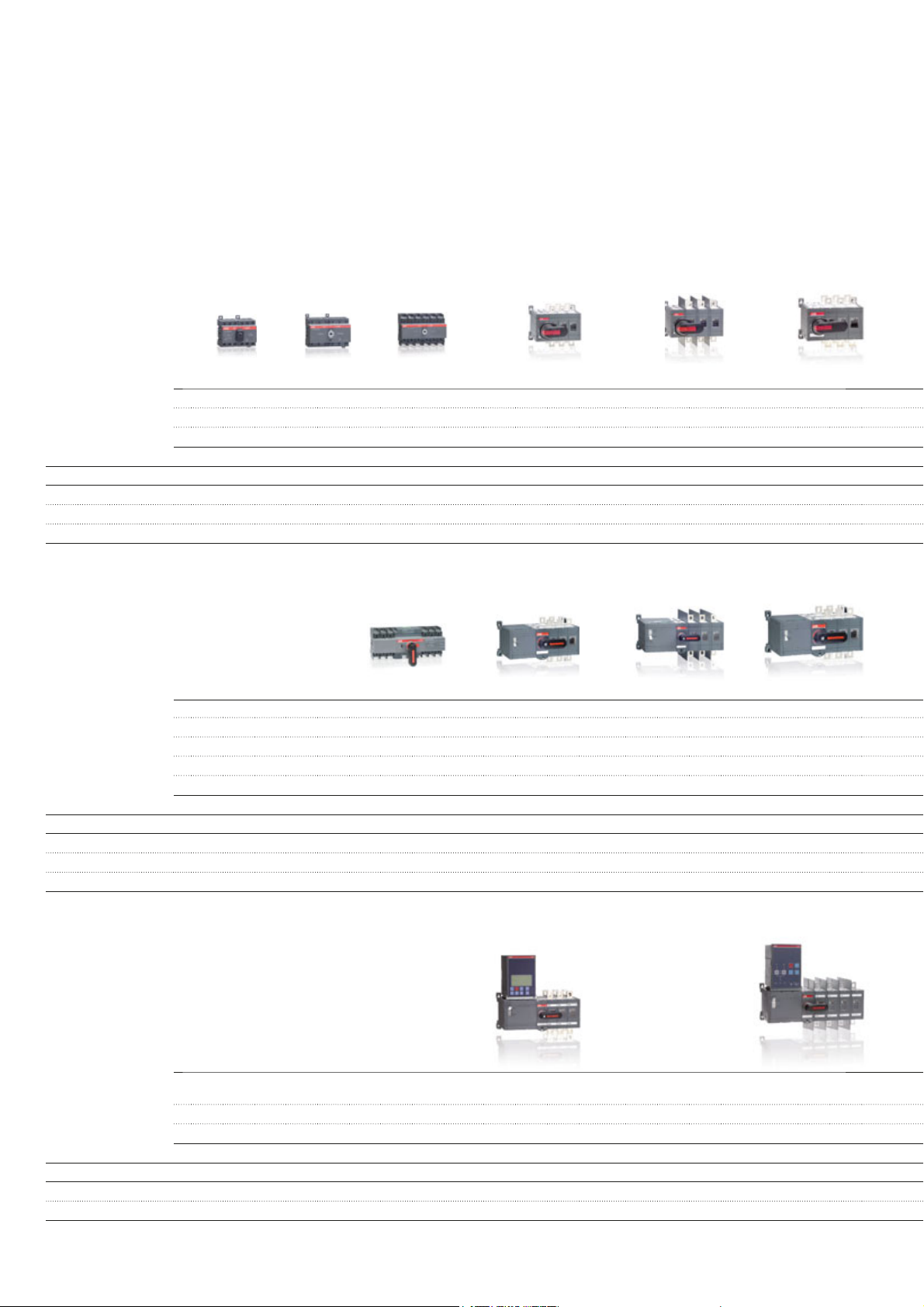
Change-over and transfer switches
16...2500A
Manual operation
OT16F OT63F OT100F OT160E OT160E_W OT315E
OT25F OT80F OT125F OT200E OT200E_W OT400E
OT40F OT250E OT250E_W
lth /A 25 32 40 63 80 115 125 160 200 250 160 200 250 315 400
le /AC-22A, < 415V 16 25 40 63 80 100 125 160 200 250 160 200 250 315 400
le /AC-23A, < 415V 16 20 23 45 75 80 90 160 200 250 160 200 250 315 400
le /AC-21B, < 415V
Motor operation
OTM40F_C OTM160E_C OTM160E_WC OTM315E_C
OTM63F_C OTM200E_C OTM200E_WC OTM400E_C
OTM80F_C OTM250E_C OTM250E_WC
OTM100F_C
OTM125F_C
lth /A 40 63 80 115 125 160 200 250 160 200 250 315 400
/AC-22A, < 415V 40 63 80 100 125 160 200 250 160 200 250 315 400
l
e
le /AC-23A, < 415V 40 63 80 80 90 160 200 250 160 200 250 315 400
le /AC-21B, < 415V
Automatic operation
OTM160E_C_D OTM160E_WC_D
OTM200E_C_D OTM200E_WC_D
OTM250E_C_D OTM250E_WC_D
lth /A 160 200 250 160 200 250
/AC-22A, < 415V 160 200 250 160 200 250
l
e
le /AC-23A, < 415V 160 200 250 160 200 250
4 Product overview | Change-over and transfer switches
Page 2
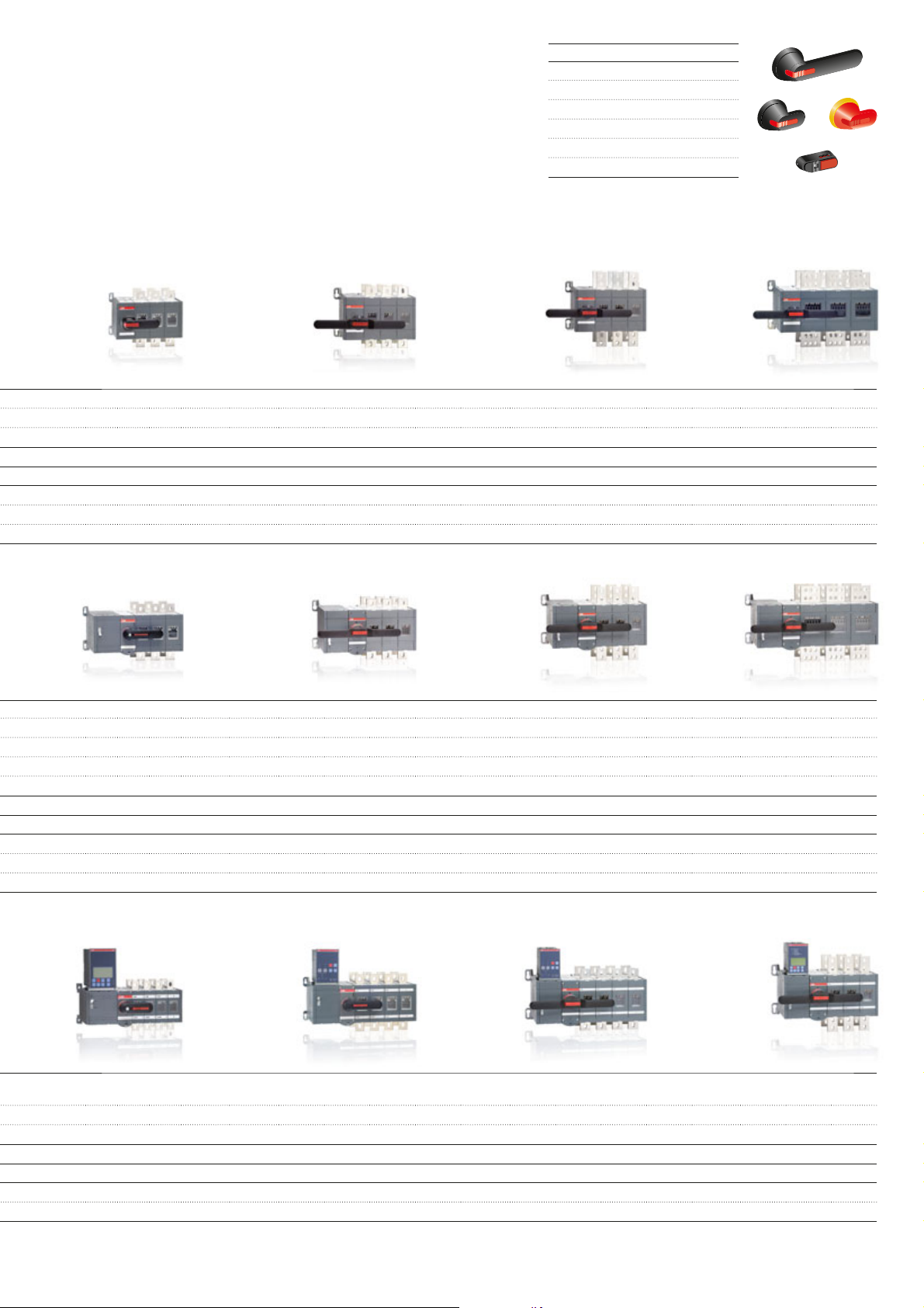
Accessories
N
O
I
O
O
F
F
I
I
I
N
O
I
O
O
F
F
Optional handles
Terminal shrouds
Extended shafts
Connecting accessories
Auxiliary contacts
Locking accessories
OT630E OT1000E OT1600E OT2000E
OT800E OT1250E OT2500E
630 800 1000 1250 1600 2000 2500
630 800 1000 1250 1600
630 800 1000 1250 1250
2000 2500
OTM630E_C OTM1000E_C OTM1600E_C OTM2000E_C
OTM800E_C OTM1250E_C OTM2500E_C
630 800 1000 1250 1600 2000 2500
630 800 1000 1250 1600
630 800 1000 1250 1600
2000 2500
OTM315E_C_D OTM630E_C_D OTM1000E_C_D OTM1600E_C_D
OTM400E_C_D OTM800E_C_D OTM1250E_C_D
315 400 630 800 1000 1250 1600
315 400 630 800 1000 1250 1600
315 400 630 800 1000 1250 1250
Change-over and transfer switches | Product overview 5
Page 3

Technical data
Manual change-over switches
OT16...125_C_
Manual change-over switches
Data according to IEC 60947-3 Switch size
Rated insulation voltage and rated
operational voltage AC20/DC20 Pollution degree 3 V
Dielectric strength 50 Hz 1min. kV
Rated impulse withstand voltage kV
Rated thermal current and rated operational / ambient 40°C In open air A
current AC20/DC20 / ambient 40°C In enclosure A
..with minimum conductor cross section Cu mm
Rated operational current, AC-21A up to 500 V A
Rated operational current, AC-22A up to 500 V A
Rated operational current, AC-23A up to 415 V A
Rated operational current / poles in series, DC-21A up to 48 V
Rated operational current / poles in series, DC-22A up to 48 V
Rated operational current / poles in series, DC-23A up to 48 V
Rated operational power, AC-23A
The kW-ratings are accurate for 3-phase 1500 400 V kW
R.P.M. standard asychronous motors 415 V kW
Rated breaking capacity in up to 415 V A
category AC-23 500 V A
Rated conditional short-circuit current I
corresponding max. allowed cut-off current î
value. The cut-off current î
fuse manufacturers (single phase test acc. to IEC60269). Max. OFA_ fuse size gG/aM A
Rated short-time withstand current I
Rated short-time making capacity
Power loss / pole With rated current W
Mechanical endurance Number of oper. cycles
Mechanical endurance / switch Number of operations Oper.
Cable size Cu-wire size suitable for mm
Terminal tightening torque Counter torque required Nm
Operating torque Typical for 3-pole switches Nm
Weight without accessories 3-pole switch kg
Data according to UL508 (Listed)
Current A
Horsepower, 3-phase 200 V HP
1)
Below 48 V, two poles in parallel up to OT80 are recommended particularly in polluted atmosphere
2)
These values are given for guidance and may vary acc. to the motor manufacturer
3)
Short circuit duration >50ms, without fuse protection
4)
Operating cycle: O - I - O - II - O
2)
(r.m.s.) and Ip (r.m.s.) 50 kA, 415 V îc (peak) kA
p
(peak) Max. OFA_ fuse size gG/aM A/A
refers to values listed by Ip (r.m.s.) 100 kA, 500 V îc (peak) kA
c
3)
c
/ ambient 60°C In enclosure A
690 V A
690 V A
440 V A
500 V A
690 V A
1)
110 V A
220 V A
440 V A
500 V A
1)
110 V A
220 V A
440 V A
1)
110 V A
220 V A
440 V A
230 V kW
500 V kW
690 V kW
690 V A
(r.m.s.) 690 V 1s kA
cw
Icm (peak) 690 V kA
4)
terminal clamps AWG
4-pole switch kg
208 V HP
240 V HP
480 V HP
600 V HP
Cycles
2
A
A
A
2
8 Technical data | Change-over and transfer switches
Page 4

OT16_ OT25_ OT40_ OT63_ OT80_ OT100_ OT125_
750 750 750 750 750 750 750
6666666
8888888
25 32 40 63 80 115 125
25 32 40 63 80 115 125
20 25 32 50 63 80 100
4 6 10 16 25 35 50
16 25 40 63 80 100 125
16 25 40 63 80 100 125
16 25 40 63 80 100 125
16 25 40 63 80 100 125
16 20 23 45 75 80 90
16 20 23 45 65 65 78
16 20 23 45 58 60 70
10 11 12 20 20 40 50
16/1 25/1 32/1 63/1 80/1 100/1 125/1
16/2 25/2 32/2 63/2 80/2 100/2 125/2
16/3 25/3 32/3 63/4 63/4 100/4 100/4
16/4 16/4 16/4 16/4 16/4
16/4 16/4 16/4 16/4 16/4
16/1 25/1 32/1 63/1 80/1 100/1 125/1
16/2 25/2 32/2 63/2 80/2 100/2 125/2
16/3 25/3 32/4 45/4 45/4 63/4 80/4
10/4 10/4 10/4 10/4 10/4
16/1 25/1 32/1 63/1 80/1 100/1 125/1
16/2 25/2 32/2 63/2 80/2 100/2 125/2
16/4 25/4 32/4 45/4 45/4 63/4 63/4
10/4 10/4 10/4 10/4 10/4
3 4 5,5 11 22 22 22
7.5 91122373745
7.5 91122373745
7.5 91122373745
7.5 9 11 15 18.5 37 45
128 160 184 360 640 640 720
128 160 184 360 464 480 560
80 88 96 160 160 320 400
6.5 6.5 6.5 13 13 16.5 16.5
40/32 40/32 40/32 100/80 100/80 125/125 125/125
17 17
100/80 100/80
0.5 0.5 0.5 1 1.5 2.5 2.5
0.7 0.7 0.7 1.4 2.1 3.6 3.6
0.3 0.6 1.6 2.8 4.5 4.0 6.3
10 000 10 000 10 000 10 000 10 000 10 000 10 000
20 000 20 000 20 000 20 000 20 000 20 000 20 000
0.75-10 0.75-10 0.75-10 1.5-35 1.5-35 10-70 10-70
18-8 18-8 18-8 14-4 14-4 8-00 8-00
0.80.80.82266
1111.21.222
0.25 0.25 0.25 0.64 0.64 0.90 0.90
0.31 0.31 0.31 0.70 0.70 1.18 1.18
16 25 40 60 80
3 7.5 10 15 20
3 7.5 10 15 20
5 7.5 10 15 20
10 15 20 30 40
10 20 25 30 40
Change-over and transfer switches | Technical data 9
Page 5

Technical data
Motorized change-over switches
OTM40...125_C_
Motorized change-over switches
Data according to IEC 60947-3 Switch size
Rated insulation voltage and rated operational voltage AC20/DC20 Pollution degree 3 V
Dielectric strength 50 Hz 1min. kV
Rated impulse withstand voltage kV
Rated thermal current and rated operational / ambient 40°C In open air A
current AC20/DC20 / ambient 40°C In enclosure A
..with minimum conductor cross section Cu mm
Rated operational current, AC-21A up to 500 V A
Rated operational current, AC-22A up to 500 V A
Rated operational current, AC-23A up to 415 V A
Rated operational current / poles in series, DC-21A up to 48 V A
Rated operational current / poles in series, DC-22A up to 48 V A
Rated operational current / poles in series, DC-23A up to 48 V A
Rated operational power, AC-23A
The kW-ratings are accurate for 3-phase 1500 400 V kW
R.P.M. standard asychronous motors 415 V kW
Rated breaking capacity in up to 415 V A
category AC-23 500 V A
Rated conditional short-circuit current I
allowed cut-off current î
values listed by fuse manufacturers (single phase test acc. to IEC60269). I
Rated short-time withstand current I
Rated short-time making capacity
Power loss / pole With rated current W
Mechanical endurance Number of oper. cycles
Mechanical endurance / switch Number of operations Oper.
Cable size Cu-wire size suitable mm
Terminal tightening torque Counter torque required Nm
Operating torque Typical for 3-pole switches Nm
Weight without accessories 3-pole switch kg
Data according to IEC 60947-6-1
Class of equipment
Rated short-time withstand current I
Conditional short-circuit current I
Corresponding fuse rating gG/aM fuse 415 V A
Rated operational current, AC-31B up to 415 V A
Rated operational current, AC-32B up to 415 V A
Rated operational current, AC-33B up to 415 V A
1)
These values are given for guidance and may vary acc. to the motor manufacturer
2)
Short circuit duration > 50ms, without fuse protection
3)
Operating cycle: O - I - O - II - O
(peak) value. The cut-off current îc refers to Max. OFA_ fuse size gG/aM A/A
c
1)
(r.m.s.) and corresponding max. Ip (r.m.s.) 50 kA, 415 V îc (peak) kA
p
2)
/ ambient 60°C In enclosure A
690 V A
690 V A
500 V A
690 V A
110 V A
220 V A
110 V A
220 V A
110 V A
220 V A
230 V kW
500 V kW
690 V kW
690 V A
(r.m.s.) 18 kA, 690 V îc (peak) kA
p
Max. OFA_ fuse size gG A
I
(r.m.s.) 50 kA, 690 V îc (peak) kA
p
Max. OFA_ fuse size gG/aM A/A
for terminal clamps AWG
(r.m.s.) 690 V 1s kA
cw
Icm (peak) 690 V kA
3)
4-pole switch kg
(r.m.s.) 690 V 0.1s kA
cw
(r.m.s.) 415 V kA
cc
Cycles
2
2
10 Technical data | Change-over and transfer switches
Page 6

OTM40_ OTM63_ OTM80_ OTM100_ OTM125_
800 800 800 800 800
66666
88888
40 63 80 115 125
40 63 80 115 125
32 50 63 80 100
10 16 25 35 50
40 63 80 100 125
40 63 80 100 125
40 63 80 100 125
40 63 80 100 125
40 63 80 80 90
40 60 60 60 70
40 40 40 40 50
40/1 63/1 80/1 100/1 125/1
40/2 63/2 80/2 100/2 125/2
40/4 63/4 80/4 100/4 100/4
40/1 63/1 80/1 100/1 125/1
40/2 63/2 80/2 100/2 125/2
40/4 63/4 80/4 80/4 80/4
40/1 63/1 80/1 100/1 125/1
40/2 63/2 80/2 100/2 125/2
40/4 63/4 63/4 63/4 63/4
7.5 15 22 22 22
18.5 30 37 37 45
18.5 30 37 37 45
22 37 37 37 45
37 37 37 37 45
320 504 640 640 720
320 480 480 480 560
320 320 320 320 400
16.5 16.5 16.5 16.5 16.5
125/125 125/125 125/125 125/125 125/125
11 11 11 11 11
125 125 125 125 125
10 10 10 10 10
63/63 63/63 63/63 63/63 63/63
2.5 2.5 2.5 2.5 2.5
3.6 3.6 3.6 3.6 3.6
1.6 2.8 3.5 4.0 6.3
10 000 10 000 10 000 10 000 10 000
20 000 20 000 20 000 20 000 20 000
2.5-25/2x2.5-16 10-70 10-70 10-70 10-70
14-4/2x14-6 8-00 8-00 8-00 8-00
66666
55555
1.37 1.37 1.37 1.37 1.37
1.60 1.60 1.60 1.60 1.60
PC PC PC PC PC
5555
50 50 50 50 50
125 125 125 125 125
40 63 80 100 125
40 63 80 100 125
40 63 80 80 80
Change-over and transfer switches | Technical data 11
Page 7

Technical data
Manual, motorized and automatic
transfer switches OT/OTM160...2500_C_
Manual / motorized change-over switches and automatic transfer switches
Data according to IEC 60947-3 Switch size OT_160_ OT_200_
Rated insulation voltage and rated Pollution
operational voltage AC20/DC20
Dielectric strength 50 Hz 1min. kV 10 10
Rated impulse withstand voltage
Rated thermal current and rated operational / ambient 40°C In open air A 160 200
current AC20/DC20 / ambient 40°C In enclosure A 160 200
..with minimum conductor cross section Cu mm
Rated operational current, AC-21A up to 500 V A 160 200
Rated operational current, AC-22A up to 500 V A 160 200
Rated operational current, AC-23A up to 415 V A 160 200
Rated operational current / poles in series, DC-21A...23A ≤ 110 V A 160/2 200/2
Rated operational power, AC-23A
The kW-ratings are accurate for 3-phase 1500 400 V kW 90 110
R.P.M. standard asychronous motors 415 V kW 90 110
Rated breaking capacity in up to 415 V A 1 280 1 600
category AC-23 500 V A 1 280 1 600
Rated conditional short-circuit I
current I
cut-off current î
The cut-off current î
listed by fuse manufacturers I
(r.m.s.) and Max. OFA_ fuse size gG/aM A/A 355/315 355/315
p
(peak) value. Ip (r.m.s.) 100 kA, 500 V îc (peak) kA 40.5 40.5
c
refers to values Max. OFA_ fuse size gG/aM A 315/315 315/315
c
(single phase test acc. to IEC60269). Max. OFA_ fuse size gG/aM A 355/315 355/315
Rated short-time withstand current I
Rated short-time making capacity
Power loss / pole With rated current W 2.4 4
Mechanical endurance Number of oper. cycles
Mechanical endurance / switch Number of operations Oper. 16 000 16 000
Terminal bolt size Metric thread diameter x length mm M8x25 M8x25
Terminal tightening torque Counter torque required Nm 15-22 15-22
Operating torque Typical for 3-pole switches Nm 7 7
Weight without accessories Manual change-over switches 3-pole switch kg 2.5 2.5
Data according to IEC 60947-6-1
Class of equipment PC PC
Rated short-time withstand current I
Rated operational current, AC-31B up to 415 V A 160 200
Rated operational current, AC-33B up to 415 V A 160 200
1)
Automatic transfer switches: operational voltage = max. 415 V AC for OTM_C2D_, OTM_C3D_ and OTM_C8D_
2)
Automatic transfer switches: pollution degree 2 for OTM_C2D_, OTM_C3D_ and OTM_C8D_
3)
Automatic transfer switches: U
4)
Utilization category B
5)
These values are given for guidance and may vary acc. to the motor manufacturer
6)
Short circuit duration > 50ms, without fuse protection
7)
Max. distance from switch frame to nearest busbar / cable support 150 mm
8)
Operating cycle: O - I - O - II - O
9)
Category AC-21B, up to 415V
10)
For manual change-over switches
11)
For motorized and automatic transfer switches
1)
degree 3
3)
kV 12 12
2)
V 1000 1000
2
70 95
690 V A 160 200
690 V A 160 200
440 V A 160 200
500 V A 160 200
690 V A 160 200
220 V A 160/2 200/2
440 V A 160/3 200/3
5)
660 V A 160/4 200/4
230 V kW 45 60
500 V kW 110 132
690 V kW 160 200
690 V A 1 280 1 600
(r.m.s.) 80 kA, 415 V îc (peak) kA 40.5 40.5
p
(r.m.s.) 80 kA, 690 V îc (peak) kA 40.5 40.5
p
(r.m.s.) 690 V 0.15s kA 15 15
cw
6)
Icm (peak)
690 V 0.25s kA 15 15
7)
8)
690 V 1s kA 8 8
690 V kA 30 30
Cycles 8 000 8 000
4-pole switch kg 3.2 3.2
Motorized and automatic transfer switches 3-pole switch kg 5.7 5.7
4-pole switch kg 6.4 6.4
(r.m.s.) 690 V 0.1s kA 15 15
cw
= 6 kV for OTM_C2D_, OTM_C3D_ and OTM_C8D_
imp
12 Technical data | Change-over and transfer switches
Page 8

OT_250_ OT_315_ OT_400_ OT_630_ OT_800_ OT_1000_ OT_1250_ OT_1600_ OT_2000_ OT_2500_
1000 1000 1000 1000 1000 1 000 1 000 1 000 1 000 1 000
10 10 10 10 10 10 10 10 10 10
12 12 12 12 12 12 12 12 12 12
250 315 400 630 800 1 000 1 250 1 600 2000 2500
250 315 400 630 800
120 185 240 2x185 2x240 2x300 2x400 2x500 3x500 4x500
250 315 400 630 800 1 000 1 250 1 600 2000
9)
2500
250 315 400 630 800 1 000 1 250 1 600
250 315 400 630 800 1 000 1 250 1 600
250 315 400 630 800 1 000 1 250 1 600
250 315 400 630 800 1 000 1 250 1 250
250 315 400 630 800 1 000 1 250 1 250
250 315 400 630 800 1 000 1 250 1 250
250 315 400 630 800 1 000 1 250 1 250
250/2 315/1
250/2 315/2
230/3 315/3 360/3 630/2 720/2
200/4 315/4 315/4 630/4
4)
400/1
4)
400/2
4)
4)
630/1 800/1
630/1 800/1
4)
630/4
4)
75 100 132 200 250 315 400 400
140 160 220 355 450 560 710 710
145 180 230 355 450 560 710 710
170 220 280 400 560 710 900 900
250 315 400 630 800 1 000 1 200 1 200
2 000 2 520 3 200 5 040 6 400 10 000 10 000 10 000
2 000 2 520 3 200 5 040 6 400 10 000 10 000 10 000
2 000 2 520 3 200 5 040 6 400 10 000 10 000 10 000
40.5 59 59 83.5 83.5 100 100 100
355/315 500/500 500/500 800/1 000 800/1 000 1 250/1 250 1 250/1 250 1 250/1 250
40.5 61.5 61.5 90 90 106 106 106
315/315 500/450 500/450 800/800 800/800 1 250/1 250 1 250/1 250 1 250/1 250
40.5 59 59 83.5 83.5
355/315 500/500 500/500 800/1 000 800/1 000
15 31 31 38 38 50 50 50 50 50
15 24 24 36 36 50 50 50 50 50
8151520205050505555
30 65 65 80 80 92 92 92 110 110
6.5 6.5 10 25 40 19 29 48 55 85
8 000 8 000 8 000 5 000 5 000 3 000 3 000 3 000 2000 2000
16 000 16 000 16 000 10 000 10 000 6 000 6 000 6 000 4000 4000
M8x25 M10x30 M10x30 M12x40 M12x40 M12x60 M12x60 M12x60 M12x60 M12x60
15-22 30-44 30-44 50-75 50-75 50-75 50-75 50-75 50-75 50-75
7161627277878787878
2.5 4.7 4.7 12.8 12.8 32.3 32.3 34.8 48 48
3.2 5.8 5.8 15.6 15.6 40.2 40.2 43.3 60 60
5.7 10.2 10.2 17.5 17.5 42 42 44 56 56
6.4 11.4 11.4 20.4 20.4 50 50 52 70 70
9)
PC PC PC PC PC PC PC PC PC PC
15 25 25 38 38 50 50 50 50 50
250 315 400 630
250 315 400 630
10)
10)
/650
/650
11)
10)
10)
/720
/650
11)
11)
1 000 1 250 1 600 2000
1 000 1 000 1 000
800
11)
800
10)
2000
Change-over and transfer switches | Technical data 13
10)
Page 9

Technical data, motor operators
Motorized change-over switches
OTM40...125_C_
Motor operator
Data according to IEC 60947 Switch size 40…125
Rated operational voltage U
Operating voltage range 0.85 - 1.1 x U
Operating time
Operating transfer time
OFF -time when operating I-II or II-I
Nominal current I
Current inrush
Operating rate Cycle 0-I-0-II-0
Overvoltage category III
Rated impulse withstand voltage U
Dielectric strength 50 Hz 1 min. kV 1.5
Impulse command Min. impulse
Terminals
Voltage supply wiring for U
Cross section Solid/stranded mm
Short-circuit protection device Max. MCB A C16
Control terminal C - II - I - O
Cross section Solid/stranded mm
Maximum cable length m 100
Terminal for state information
Terminal for state information
Also used with the OMD automatic control unit Rating A 3
Common, voltage supply 1
Position of switch I 2
Position of switch II 3
Handle attached or motor operator locked 4
Short-circuit protection device Max. MCB A C2
Control terminal for OMD automatic control unit
Control terminal for OMD automatic control unit
1)
1)
n
1)
e
1)
1)
Max. short-time ≤ 10 cycles cycles/min 10
imp
e
Pollution degree 3 V AC/DC 110 - 240
90° I-0, 0-I, 0-II, II-0 s 0.5-1.0
50/60 Hz
180° I-II, II-I s 1.2-1.5
180° I-II, II-I s 0.4-0.8
Max. continuous cycles/min 1
duration ms 100
1
2
4
3
II
I
Solid/stranded mm
Solid/stranded mm
A 0.2-0.5
A 1.5-3.0
kV 4
2
2
2
2
PE - N - L
1.5 - 2.5
1.5 - 2.5
1.5
AC-1/250V
1.5 - 2.5
e
Common, voltage supply from motor operator 1 V DC 24
Close switch I or open switch II 2 V DC 24
Close switch II or open switch I 3 V DC 24
Operating temperature °C -25…+55
Transportation and storage temperature °C -40…+70
Max. altitude m 2000
Protection degree (front panel) IP20
1)
Under nominal conditions
mW 500
mW 500
14 Technical data | Change-over and transfer switches
Page 10

Technical data, motor operators
Motorized change-over switches
OTM160...2500_C_
Motor operator
Data according to IEC 60947 Switch size 160…250 315...400 630…800 1000…1600 2000…2500
Rated operational voltage U
Operating voltage range 0,85 - 1,1 x U
Operating time
Operating transfer time
OFF -time when operating 180° I-II, II-I 220-240VAC s 0.4-1.0 0.4-1.0 0.4-1.0 0.5-1.5 0.5-1.5
I-II or II-I
Nominal current I
Current inrush
Overload fuse Type / I
Operating rate Cycle 0-I-0-II-0
Overvoltage category III
Rated impulse withstand voltage U
Dielectric strength 50 Hz 1 min. kV 1.5
Impulse command Min. impulse
Terminals
Voltage supply wiring for U
Cross section solid/stranded mm
Short-circuit protection device max. MCB A C16
Control terminal (no SELV) C - II - I - O
Cross section solid/stranded mm
Maximum cable length m 100
State information of locking (no SELV)
Handle attached or motor operator locked 11-12-14 (C/O) 5A/250V/cosϕ=1
Locking motor operator 23-24 (NO) 5A/250V/cosϕ=1
Short-circuit protection device Max. MCB A C2
Protection degree IP20
Operating temperature °C -25…+55
Transportation and storage temperature °C -40…+70
Max. altitude m 2000
1)
Under nominal conditions
1)
1)
1)
1)
n
1)
Max. short-time ≤ 10 cycles 220-240VAC cycles/min 10 10 10 5 5
Pollution degree 3
e
90° I-0, 0-I, 0-II, II-0 220-240VAC s 0.4-1.0 0.4-1.0 0.4-1.0 0.5-1.5 0.5-1.5
e
50/60 Hz V AC 220 - 240
110-125VAC/DC s 0.5-1.5 0.5-1.5 0.6-1.2 0.5-1.5 0.5-1.5
180° I-0-II, II-0-I 220-240VAC s 1.0-2.0 0.9-2.0 0.9-2.0 1.5-3.0 1.5-3.0
/ Capacity 220-240VAC mA T/315/H T/500/H T/1000/H T/2000/H T/2000/H
n
Max. continuous 220-240VAC cycles/min111 0.5 0.5
imp
110-125VAC/DC s 1.1-2.5 1.2-2.6 1.2-3.0 1.5-3.0 1.5-3.0
110-125VAC/DC s 0.4-1.1 0.5-1.5 0.6-1.5 0.5-1.5 0.5-1.5
110-125VAC/DC A 0.5 0.6 0.8 3.0 3.0
110-125VAC/DC A 2.1 2.5 4.6 13.3 13.3
110-125VAC/DC mA T/500/H T/630/H T/1000/H T/4000/H T/4000/H
Size mm 5x20 5x20 5x20 5x20 5x20
110-125VAC/DC cycles/min111 0.5 0.5
110-125VAC/DC cycles/min 10 10 10 5 5
48VDC s 0.5-1.5 0.4-1.0 0.6-1.6 0.5-1.5 0.5-1.5
24VDC s 0.4-1.0 0.4-1.0 0.5-1.5 1.0-2.0 1.0-2.0
48VDC s 1.4-2.5 1.0-2.0 1.3-3.0 1.5-3.0 1.5-3.0
24VDC s 1.0-2.0 1.0-2.0 1.1-2.5 2.0-3.5 2.0-3.5
48VDC s 0.5-1.1 0.4-1.0 0.7-1.6 0.5-1.5 0.5-1.5
24VDC s 0.4-1.0 0.4-1.0 0.5-1.5 0.8-1.7 0.8-1.7
220-240VAC A 0.2 0.5 0.7 1.8 1.8
48VDC A 1.1 2.1 2.6 5.3 5.3
24VDC A 3.3 4.2 4 8.0 8.0
220-240VAC A 1.3 2.1 2.8 7.7 7.7
48VDC A 4.4 8.3 8.4 22.4 22.4
24VDC A 16.8 17.5 22.4 26.6 26.6
48VDC A T/1,25/H T/2,5/H T/2,5/H T/5/H T/5/H
24VDC A T/4,0/H T/5,0/H T/5,0/H T/10/H T/10/H
48VDC cycles/min111 0.5 0.5
24VDC cycles/min111 0.5 0.5
48VDC cycles/min 10 10 10 5 5
24VDC cycles/min 10 10 10 5 5
duration ms 100
V AC/DC 110 - 125
V DC 48
V DC 24
kV 4
2
2
PE - N - L
1.5 - 2.5
1.5 - 2.5
e
Change-over and transfer switches | Technical data 15
Page 11

Technical data, power circuit
Automatic transfer switches
Technical data for automatic transfer switches, power circuit
OTM_C2D_ (OMD200)
Rated operational voltage U
Phase - Neutral 120 - 240 V AC +/- 20 %
Rated frequency 50 / 60 Hz +/- 10 %
Rated impulse withstand voltage U
OTM_C3D_ (OMD300)
Rated operational voltage U
Phase - Neutral 120 - 240 V AC +/- 20 %
Rated frequency 50 / 60 Hz +/- 10 %
Rated impulse withstand voltage U
OTM_C8D_ (OMD800)
Rated operational voltage Ue on 3 phase system 100 - 415 V AC +/- 20 %
Phase - Neutral 57,7 - 240 V AC +/- 20 %
Rated operational voltage U
Rated frequency 50 / 60 Hz +/- 10 %
Rated impulse withstand voltage U
AUX voltage
Operating temperature - 5…+40°C
Transportation and storage temperature - 25…+70°C
Altitude Max.2000m
1)
If on 1 phase system the voltage level is between 57,7 – 109 V AC, AUX voltage supply must be used
1)
e
imp
e
imp
on 1 phase system
e
imp
1)
208 - 415 V AC +/- 20 % + N
6 kV
208 - 415 V AC +/- 20 % + N
6 kV
57,7 - 240 V AC +/- 20 %
6 kV
24 V DC - 110 V DC (-10 to 15 %)
16 Technical data | Change-over and transfer switches
Page 12

Technical data, motor operator
Automatic transfer switches
Technical data for motor operator, control circuit
Motor operator, control circuit OTM160…250 OTM315…400 OTM630…800 OTM1000…1600
Rated operational voltage U [V] Pollution degree 3 50/60 Hz 220 - 240 V AC
Operating voltage range 0,8…1,2 x U
Operating times See the table below
Nominal current I
Current Inrush
Overload fuse Type / In / Capacity mA T/315/H T/500/H T/1000/H T/2000/H
Operating rate Cycle 0 - I - 0 - II - 0
Max. short-time ≤ 10 cycles cycles / min 10 10 10 5
Overvoltage category III
Rated impulse withstand voltage U
Dielectric strength 50 Hz 1 min. kV 1.5
Terminals
Voltage supply wiring for U
Cross section solid/stranded mm
Short-circuit protection device max. MCB A C16
State information of locking (no SELV)
Cross section solid/stranded mm
Locking motor operator 23-24 (NO) 5A/250V/cosϕ=1
Short-circuit protection device Max. MCB A C2
Protection degree IP20
Operating temperature °C -25…+55
Transportation and storage temperature °C -40…+70
Max. altitude m 2000
a)
n
a)
Size mm 5x20 5x20 5x20 5x20
Max. continuous cycles / min 1 1 1 0.5
imp
A 0.2 0.5 0.7 1.8
A 1.3 2.1 2.8 7.7
kV 4
2
2
PE - N - L
1.5 - 2.5
1.5 - 2.5
e
Operating times
Type
OTM160…250_C2D_ 2.0 - 4.0 0.4 - 1.0
OTM160…250_C3D_ 2.0 - 4.0 0.4 - 1.0
OTM160…250_C8D_ 1.5 - 3.0 0.4 - 1.0
OTM315…400_C2D_ 2.0 - 5.0 0.4 - 1.0
OTM315…400_C3D_ 2.0 - 5.0 0.4 - 1.0
OTM315…400_C8D_ 1.5 - 3.0 0.4 - 1.0
OTM630…800_C2D_ 2.0 - 5.0 0.4 - 1.0
OTM630…800_C3D_ 2.0 - 5.0 0.4 - 1.0
OTM630…800_C8D_ 1.5 - 3.0 0.4 - 1.0
OTM1000…1600_C2D_ 3.0 - 6.0 0.6 - 1.5
OTM1000…1600_C3D_ 3.0 - 6.0 0.6 - 1.5
OTM1000…1600_C8D_ 2.5 - 4.0 0.6 - 1.5
a)
Under nominal conditions
Operating transfer time
I - II, II - I [s]
a)
OFF-time when operating
I - II, II - I [s]
a)
Change-over and transfer switches | Technical data 17
Page 13

Technical data
Automatic control units and
dual power source
Technical data for automatic control units OMD200/300/800
OMD200 and OMD300
Rated operational voltage U
Phase - Neutral 120 V AC - 277 V AC +/- 20%
Rated frequency 50 / 60 Hz +/- 10%
Voltage sensing precision 5%
Frequency sensing precision 1%
Relay ratings:
X21, X22 12 A, AC1, 250 V / 12 A, DC1, 24 V
X23, X24 8 A, AC1, 250 V / 8 A, DC1, 24 V
X26, X27, X28 10 A, AC1, 250 V / 5 A, DC1, 24 V
Rated impulse withstand voltage, U
Overvoltage category III
Pollution degree 2
OMD800
Rated operational voltage Ue on 3 phase system 100 V AC - 480 V AC +/- 20%
Phase - Neutral 57,7 V AC - 277 V AC +/- 20%
Rated operational voltage Ue on 1 phase system
Rated frequency 50 / 60 Hz +/- 10%
Voltage sensing precision 1%
Frequency sensing precision 1%
Relay ratings:
X21, X22, X24 12 A, AC1, 250 V / 12 A, DC1, 24 V
X23 8 A, AC1, 250 V / 8 A, DC1, 24 V
X29 5 A, AC1, 250 V / 6 A, DC1, 24 V
Rated impulse withstand voltage, U
Overvoltage category III
Pollution degree 2
AUX voltage
Protection rating for the front panel IP40
Operating temperature – 20...+ 60 °C
Transportation and storage temperature – 25...+ 80 °C
Altitude Max. 2000m
Humidity
With condensation 5 %...98 %
Without condensation 5 %...90 %
1)
If on 1 phase system the voltage level is between 57,7 – 109 V AC, AUX voltage supply must be used
1)
e
imp
1)
imp
208 V AC - 480 V AC +/- 20% + N
6 kV
57,7 V AC - 277 V AC +/- 20%
6 kV
24 V DC - 110 V DC (-10% to +15%)
Technical data for dual power source ODPSE230C
Dual power source ODPSE230C
Rated operational voltage U [V] 220…240 V AC +/- 20%
Rated frequency 50 / 60 Hz +/- 10%
Short-circuit protection device Max. MCB 4 A
Nominal output current I
Startup time Max. 1.0 s (with 230 V AC)
Operating transfer time LN1 - LN2 or LN2 - LN1 Max. 0.5 s (with 230 V AC)
Cable size 0,2…2,5 mm
Rated impulse withstand voltage, U
Overvoltage category III
Pollution degree 3
Protection rating for the front panel IP20
Operating temperature – 25...+ 60 °C
Transportation and storage temperature – 40...+ 70 °C
Altitude Max. 2000m
18 Technical data | Change-over and transfer switches
[A] 4 A
n
imp
4 kV
2
Page 14

Technical data
UL/CSA manual change-over switches
OT200...800U_C_ and auxiliary contacts
Manual change-over switches
Data according to UL and CSA Switch size OT200U_ OT400U_ OT600U_ OT800U_
Standards UL98 UL98 UL98 UL98
General use ratings - 1- or 3-phase ratings V 600 600 600 600
Horsepower, 3-phase ratings 240V HP 75 125 200 250
Short-circuit ratings Required protection Circuit breaker kA 14 25 35 42
Data according to IEC 60947-3
Rated insulation voltage and rated
operational voltage AC20/DC20 Pollution degree 3 V 1000 1000 1000 1000
Dielectric strength 50 Hz 1min. kV 10 10 10 10
Rated impulse withstand voltage kV 12 12 12 12
Rated thermal current and rated / ambient 40°C In open air A 250 400 800 1600
operational current AC20/DC20
..with minimum conductor cross section Cu mm
Rated operational current, AC-21A up to 690 V A 250 400 800 1600
Rated operational current, AC-22A up to 500 V A 250 400 800 1600
Rated operational current, AC-23A up to 500 V A 250 400 800 1250
Rated conditional short-circuit I
current I
corresponding max. allowed I
cut-off current î
Rated short-time withstand current I
Rated short-circuit making capacity I
Mechanical endurance Number of operating cycles
Mechanical endurance / switch Number of operations Oper. 16000 16000 10000 6000
Terminal bolt size Metric thread diameter x length mm M8x25 M10x30 M12x40 M12x60
Terminal tightening torque Counter torque required Nm 15...22 30...44 50...75 50...75
Operating torque 3-pole switches Nm 7 16 27 78
Weight without accessories 3-pole switch kg 2.8 5.0 13.1 34,8
Data according to IEC 60947-6-1
Class of equipment PC PC PC PC
Rated short-time withstand current I
Rated operational current, AC-31B up to 415 V A 250 400 800 1600
Rated operational current, AC-33B up to 415 V A 250 400 800 1000
1)
2)
(r.m.s.) and Max. OFA_ fuse size gG/aM A 315/315 500/450 800/800 1250/1250
p
peak value
c
The fuse in single-phase test according to IEC 60269
Operating cycle: O - I - O - II - O
1)
(r.m.s.) : 100 kA, 500 V îc (peak) kA 40.5 61.5 90 106
p
(r.m.s.) : 80 kA, 690 V îc (peak) kA 40.5 59 83,5
p
Max. OFA_ fuse size gG/aM A 355/315 500/500 800/1000
(r.m.s.) 690V, 1s kA 8 15 20 50
cw
(peak) 690V kA 30 65 80 92
cm
4-pole switch kg 3.5 6.1 15.9 43,3
(r.m.s.) 690 V 0.1s 15 25 38 50
cw
Class J/L fuse kA 65/100 100 100 100
Class RK5 fuse kA 100
2)
480V HP 150 250 450 500
600V HP 200 350 500 500
…fuse size A 400/200 600 800 800
…fuse size A 600
690 V A 250 400 800 1600
690 V A 250 400 800 1250
Cycles 8000 8000 5000 3000
CSA 22.2#4 CSA 22.2#4 CSA 22.2#4 CSA 22.2#4
A 200 400 600 800
2
120 240 2x240 2x500
Auxiliary contacts
Technical data for auxiliary contacts according to IEC 60947-5-1
For OA1G_, OA2G_, OA3G_, OA7G_, OA8G_
U
e
230 6 24 10 240 2 50
400 4 72 4 290 0.8 60
415 4 125 2 250 0.55 70
690 2 250 0.55 140 0.27 70
AC15 DC12 DC13
/[V] Ie/[A] Ue/[V] Ie/[A] P/[W] Ie/[A] P/[W]
440 0.1 44
Change-over and transfer switches | Technical data 19
 Loading...