

ABB CDD Product Manual
ABB solar inverters
Product manual
CDD (concentrator data device)
- 2 -
001CV
IMPORTANT SAFETY INSTRUCTIONS
This manual contains important safety instructions that must be followed during installation
and maintenance of the CDD.
It is required that the CDD be installed with any ABB MICRO inverter in compliance with
UL1741, for the purpose of indication and resetting of ground faults.
SAVE THESE INSTRUCTIONS!
Keep this document in a safe place near the inverter for easy access during installation and
maintenance.
THE INSTALLER MUST READ THIS DOCUMENT IN ITS ENTIRETY BEFORE
INSTALLING OR COMMISSIONING THIS EQUIPMENT.
This operating manual is a valid guide that will enable users to work safely, install the CDD
(concentrator data device) and carry out the operations necessary for keeping the equipment in
good working order.
Warranty conditions can be found on the product page of the website. NOTE: Any changes or
modications not approved by the responsible party could void the user authority to operate
the equipment.
FCC REMARKS
The equipment has been tested and found to comply with the limits for a Class B digital
device, pursuant to Part 15 of the FCC Rules. These limits are designed to provide reasonable
protection against harmful interference in a residential installation. This equipment generates,
uses and can radiate radio frequency energy and, if not installed and used in accordance with
the instructions, may cause harmful interference to radio communications.
However, there is no guarantee that interference will not occur in a particular installation. If
this equipment does cause harmful interference to radio or television reception, which can be
determined by turning the equipment off and on, the user is encouraged to try to correct the
interference by one or more of the following measures:
• Reorient or relocate the receiving antenna.
• Increase the separation between the equipment and receiver.
• Connect the equipment into an outlet on a circuit different from that to which the receiver
is connected.
• Consult the dealer or an experienced radio/TV technician for help.
- 3 -
001CV
Product Manual
CDD - concentrator data device
1 - Introduction and safety
2 - Plan the installation
3 - CDD display operations
4 - Connect and congure the CDD
5 - Acquire the MICRO inverters
6 - System monitoring
7 - Appendix
CDD Product manual
BCG.00613.1_AA, NA Rev 1.0
© Copyright 2014 ABB. All Rights Reserved.

- 4 -
002TC
Contents
Introduction and safety ...................................................................................................................... 7
Warnings in this document ...................................................................................................................7
Intended use ............................................................................................................................................7
Available versions ..................................................................................................................................8
Product label .........................................................................................................................8
Regulatory nameplate ..........................................................................................................8
Plan the installation ........................................................................................................................... 9
Description of the CDD ..........................................................................................................................9
System integration ...............................................................................................................................10
Select the installation location ............................................................................................................11
Evaluate the installation position .......................................................................................................12
Mount the CDD ......................................................................................................................................14
Connect and congure the CDD .................................................................................................... 15
Connect the CDD ..................................................................................................................................15
Wireless connection to the internet ...................................................................................................16
Open networks with a MAC address filter .......................................................................16
Secure networks without a MAC address filter ...............................................................17
Secure networks with a MAC address filter.....................................................................17
Autoconnection configuration ..........................................................................................17
DHCP configuration ............................................................................................................18
IP address view ...................................................................................................................18
Ethernet connection to the internet ...................................................................................................19
Firmware upgrade ................................................................................................................................20
CDD display operations .................................................................................................................. 21
LED and display operations ................................................................................................................21
Description of the display menus .......................................................................................................22
General Information cyclical display ................................................................................24
Basic information menu .....................................................................................................24
Main menu - Statistics ........................................................................................................24
Main menu - View information ...........................................................................................25
Main menu - Change settings ............................................................................................25
Acquire the MICRO inverters ......................................................................................................... 27
Acquisition process ............................................................................................................................27
Acquire the MICRO inverters using the CDD display menu ............................................................ 27
Acquire the MICRO inverters using a computer and the integrated web server ..........................28

- 5 -
002TC
System monitoring .......................................................................................................................... 33
Remote monitoring on the Easy View web portal ............................................................................33
Self-registration procedure ................................................................................................33
Aurora vision plant viewer .................................................................................................35
Local monitoring using the CDD web server ....................................................................................36
HOME page ..........................................................................................................................36
VIEW menu ..........................................................................................................................37
CONFIG menu .....................................................................................................................38
EVENTS menu .....................................................................................................................40
UPGRADE menu .................................................................................................................40
REGISTRATION menu ........................................................................................................42
HELP menu ..........................................................................................................................42
Appendix ........................................................................................................................................... 43
The MICRO inverter system ................................................................................................................43
Characteristics of MICRO inverters ..................................................................................43
Description of the CDD .....................................................................................................44
Alarm messages and codes ................................................................................................................44
Making a service call ............................................................................................................................49
Routine maintenance ...........................................................................................................................49
Technical data and types .....................................................................................................................49
Wireless routers compatible with CDD ..............................................................................................50

- 6 -
002TC
- 7 -
003CH1
Warnings in this document
This is a list of special safety symbols used in this manual that highlight potential safety risks and/or useful
information. The symbol usage is described below:
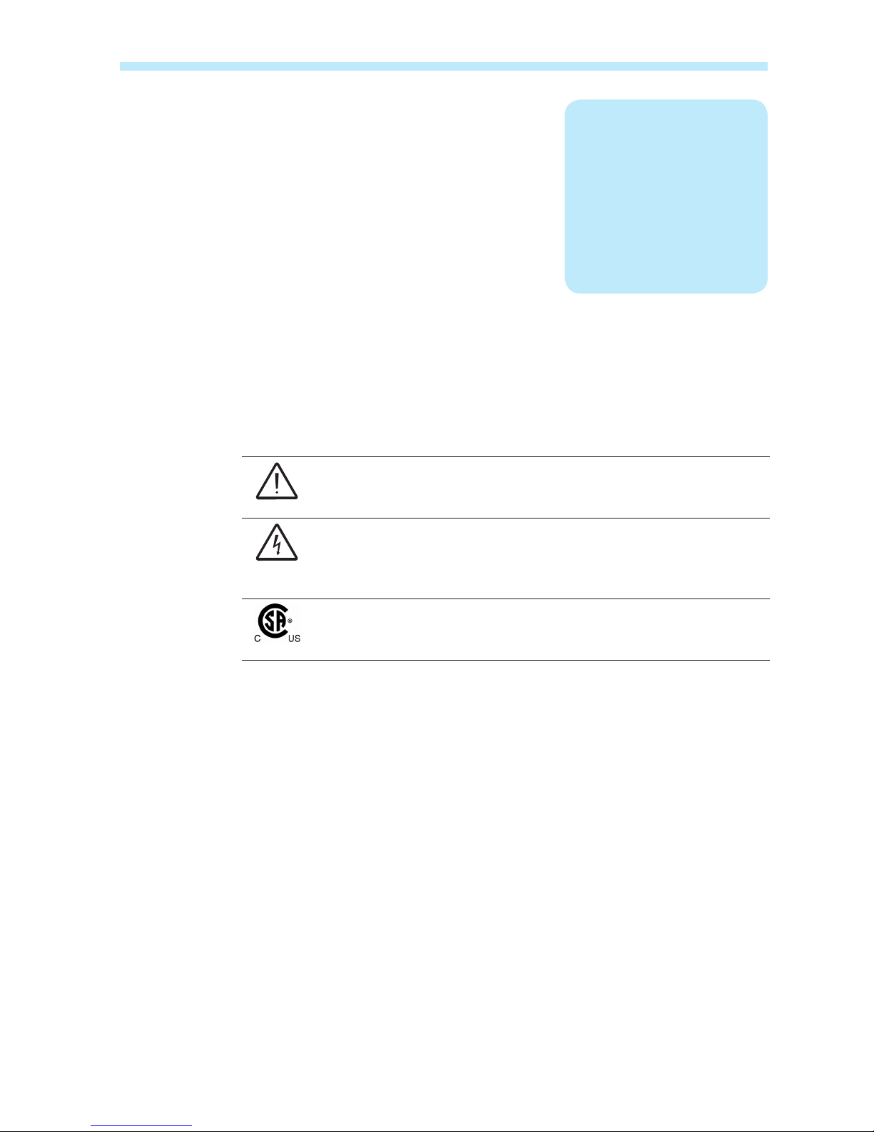
CAUTION
The reader should stop, use caution and fully understand the operations
explained before proceeding.
DANGEROUS VOLTAGE
The MICRO inverter product works with high voltages. All work on the
inverter must follow the described documentation and must comply with all
prevailing codes and regulations associated with high voltages.
UL60950-1 Safety of Information Technology Equipment – General
Requirements: Part 1; CSA 60950-1-07 Safety of Information Technology
Equipment – General Requirements: Part 1
Intended use
This equipment is a device designed to congure and control a network of ABB MICRO inverters, using radio
communication and to supply data relating to the system, using a wireless connection or an Ethernet port, to
an internet or local portal for monitoring.
• The device cannot be used in environments where there are particular restrictions on the use of radio
waves.
• The device used to transmit data to the ABB portal requires a user-supplied router connected to the internet.
The cost of connection is to be paid by the end user.
1
Introduction and safety
- 8 -
004CC1
1- Introduction and safety
Available versions
The CDD described in this manual is available in a single version suitable for all countries of installation. It is
required that the CDD be installed with any MICRO inverter in compliance with UL1741, for the purpose of
indication and resetting of ground faults.
The device can be associated with the following MICRO inverter equipment from ABB:
0.25 kW models MICRO-0.25-I-OUTD-US-208/240
0.3 kW models
MICRO-0.3-I-OUTD-US-208/240
MICRO-0.3HV-I-OUTD-US-208/240
Product label
The sample product label is afxed to the inverter and provides the following information:
CDD Part Number
CDD Serial Number
WIFI communication MAC address
Radio frequency communication MAC address
Ethernet MAC address
When registering the CDD on the Easy View portal, the MAC RF (radio frequency)
address is used as the product identication code (see System monitoring, Part 6).
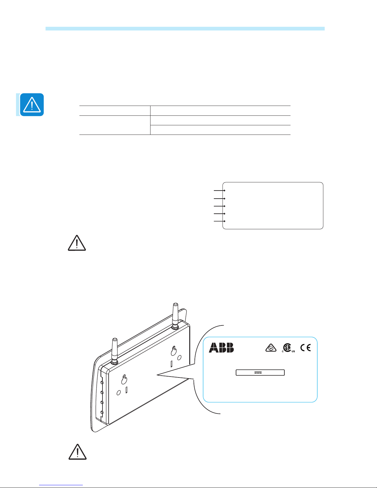
Regulatory nameplate
The nameplate shown is afxed to the inverter and provides the following information:
Technical data reported in this manual does not replace the data on the labels afxed
to the equipment.
P/N: PPPPPPPPPPP
S/N: YYWWSSSSSS
MAC WIFI:
MAC RF:
MAC ETH:
A1:B1:C1:D1:E1:F1
A2:B2:C2:D2:E2:F2:G2:H2
A3:B3:C3:D3:E3:F3
CONCENTRATOR DATA DEVICE
MODEL:
CDD
®
Contains FCC ID: X6W-EMBZ
INPUT DC : 5V , 0.5 A
This device complies with Part 15 of the FCC Rules. Operation is subject to the
following twoconditions: (i.)this device maynot cause harmful interferenceand
(ii.) this device must accept any interference received, including interference
that maycause undesired operation.
Contains FCC ID: W70ZG2100-ZG2101
www.abb.com/solar
Made in Italy
- 9 -
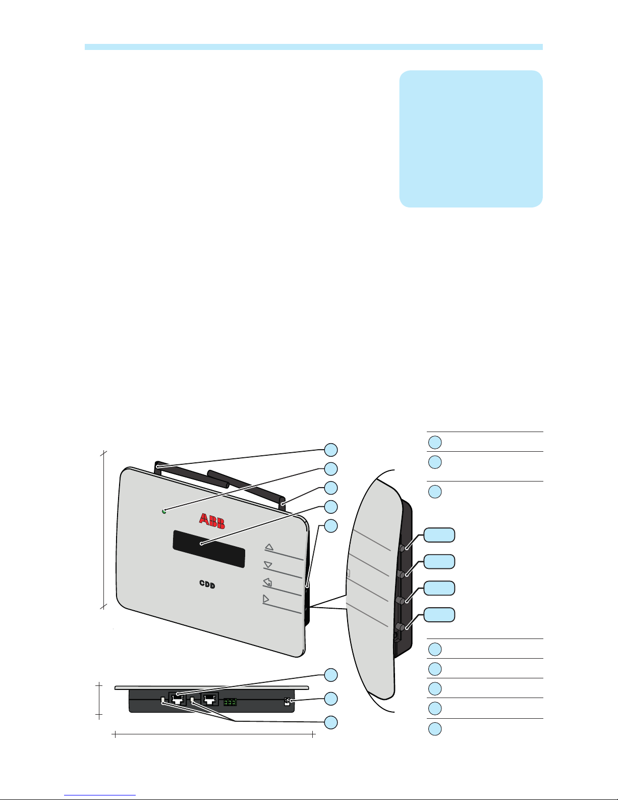
005CH2
Description of the CDD
The ABB MICRO Inverters associated with the CDD can be monitored using the CDD display, the CDD web
server interface, or from the Aurora Vision monitoring portal.
The CDD display allows simultaneous monitoring of all the associated inverters. The following information can
be viewed by navigating in the display menu:
• Operating status and statistics of each MICRO inverter
• Operating status of the connection to the internet/local network
• Alarm messages and fault indicators
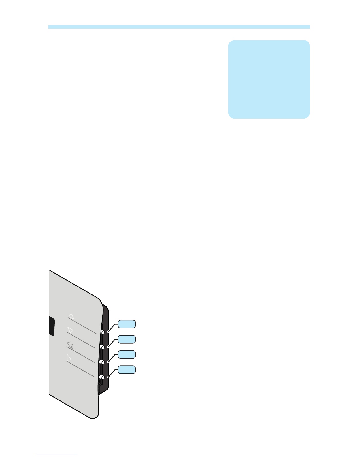
The menus are navigated by means of buttons on the side of the CDD.
01
Wireless antenna
02
Status LED
(not on all models)
03
Radio antenna
(MICRO inverter)
04
Display
05
Button pad
06
Ethernet port
07
Power connector
08
Ethernet communi cation status LED
2
Plan the installation
180mm
7.08”
25mm
0.98”
150mm
5.90”
01
02
03
04
05
06
07
08
UP
DOWN
ESC
ENTER
- 10 -
006CC2
2 - Plan the installation
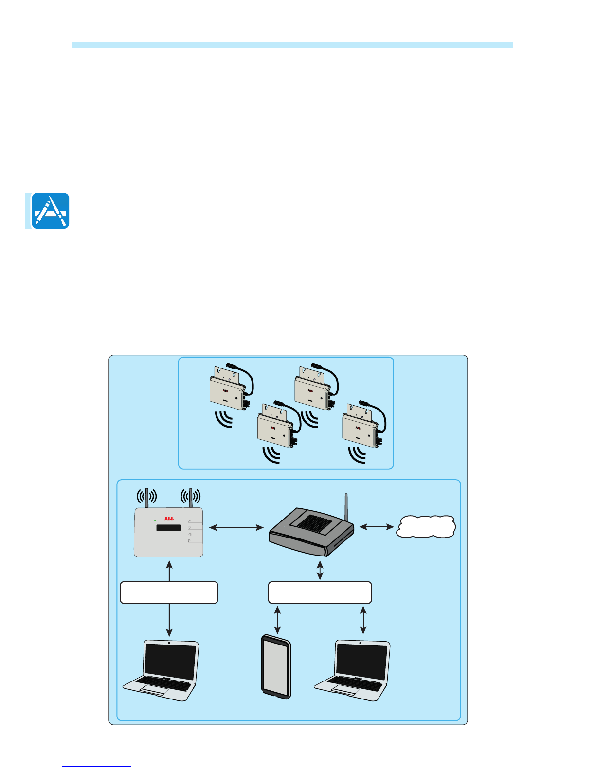
System integration
The diagram below shows several MICRO inverters communicating with a CDD, which in turn connects, by
Ethernet or wireless, to a PC or a router connected to the internet. It is also possible to manage and monitor
the system using a PC or Smartphone with internet access by registering on the Aurora Vision Plant Viewer.
The CDD device must be congured in order to commission the PV system. The following congurations must
be completed on the CDD for proper operation of the system:
• Acquisition of MICRO inverters
• Setting geographical parameters
• Setting of grid standard for the country/region of installation.
These operations can be carried out using the CDD display or the Web Server integrated in the CDD. When
conguring using the Web Server it is necessary to connect the CDD to a PC via Ethernet or Wireless (see
conguration and connection details in part 4).
Once the conguration has been completed, the device can be registered on the Plant Viewer web portal using
an internet connection, which allows remote monitoring of the MICRO inverters making up the PV system.
CDD
Internet
Smartphone
Tablet
Home Router
Desktop
Laptop
Desktop
Laptop
Local monitoring and settings
(internal web server)
Ethernet or
802.11
Radio IEEE 802.15.4
Ethernet or 802.11
Ethernet
802.11
Remote monitoring and settings
(internal web server)
- 11 -
006CC2
2 - Plan the installation
Select the installation location
It is recommended to undertake connection, conguration and acquisition operations
before mounting the CDD in a permanent location.
During acquisition of the inverters in part 5, it can be determined if reception from the
inverters and from the wireless router is sufcient, or if the position or location should
be changed.
Consider the following before installing the MICRO/CDD system:
• Evaluate possible obstacles that can restrict or nullify the radio communication among MICROs and CDD.
• Analyze the communication quality considering the possibility of having to extend the radio antenna
externally (CDD Antenna Extension Cable).
• Each CDD has a capacity to monitor up to 30 MICRO inverters; for more than 30 MICRO inverters, it is
necessary to install more than one CDD.
• For wireless (WLess) connection with a router, make sure the router is available on the compatibility list
found in the appendix, part 7, and available online at www.abb.com/solarinverters.
• For Ethernet communication, there must be an unused Ethernet port on the router.
• For installations with multiple CDDs, it is recommended to acquire all MICRO inverters before mounting
them on the roof, using the “MICRO preinstallation kit” and related guidelines.
• Choose a place close to an electrical outlet where the bottom part of the device, (where connections are
present), remains accessible.
• Because the CDD uses radio waves to transmit and receive data, it is important to assess this factor in
choosing the installation position.
Walls in reinforced cement and surfaces covered in metal (doors, shutters, etc.) can markedly reduce the
reach of the device as noted below.
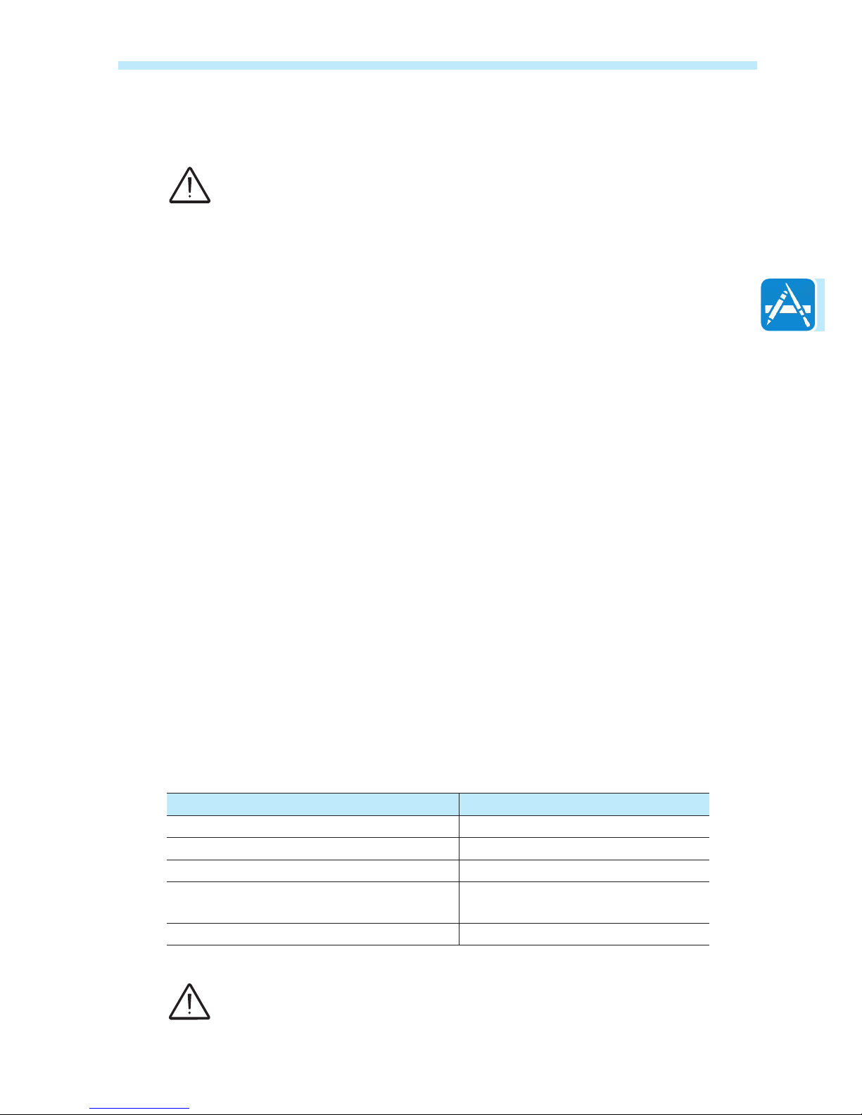
Material Relative signal range reductions
Open Field Approximately 100 m
Wood / Glass 0 – 10%
Stone / Pressed cardboard 10 – 40%
Reinforced concrete (reduction increases
with amount of reinforcement)
10 – 90%
Metal Up to 100%
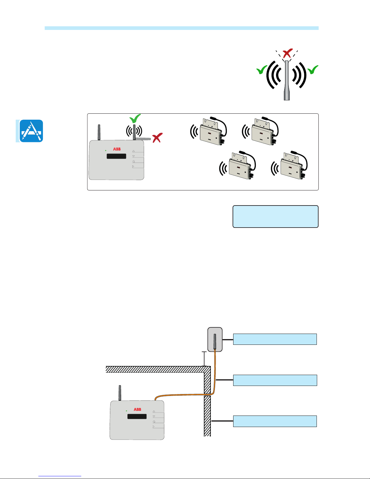
The radio signal level between the CDD and MICRO inverter can be increased in several
ways as illustrated below:
- 12 -
006CC2
2 - Plan the installation
Evaluate the installation position
The radio signal can be limited by obstacles and distance.
In order to boost the signal strength, position the antenna of the CDD in a parallel
line to the inverters. The antenna has a deadzone at the tip that should not be facing
the inverters.
When conguring the CDD and acquiring the
inverters in part 4 and 5, it may be necessary to
adjust the positioning of the antenna. The RF signal
quality is shown in the CDD display (see part 3).
An extension cable for the antenna can also be installed. The cable allows the antenna to be installed at a
distance from the CDD to go over or around possible obstacles to the radio signal.
The extended antenna can be installed in an outdoor rated plastic box (see technical note online “Improving
CDD Wireless Signal Reception” for detailed instructions), 15cm/6in above a roof and in line-of-sight of PV
panels. The extended antenna could also use the existing conduits of residential electrical systems or TV antennas to bring the CDD antenna outside.
CDD
Plant quality
High (65%)
CDD
15cm / 6in
Radio Antenna
Antenna ExtensionCable
Radio signal obstacle
- 13 -
006CC2
2 - Plan the installation
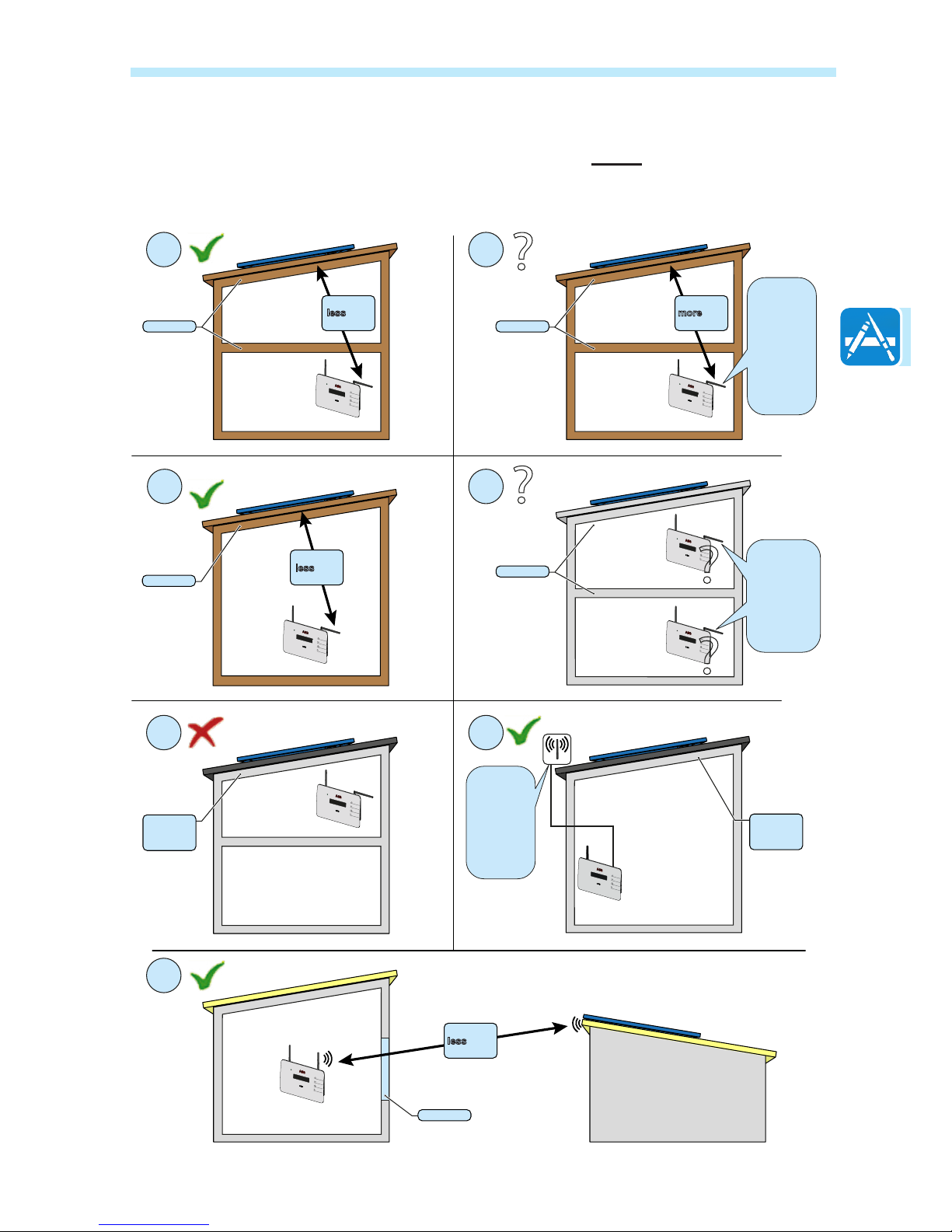
Before permanently mounting the system it is important to consider the possible scenarios shown
below and evaluate the right position for the CDD and MICRO inverters.
The distances used in the examples are between the CDD and the closest MICRO inverter available.
1 2
3
5 6
4
7
?
?
?
?
Wooden
Wooden
Concrete
Windows
Wooden
Distance
less
than
7.5m/25ft
Distance
less
than
10m/33ft
Distance
less
than
30m/100ft
Metal or
reinforced
concrete
Metal or
reinforced
concrete
Distance
more
than
7.5m/25ft
Evaluate the
RF signal
quality and
the possibility
to extend the
RF antenna
externally
Evaluate the
RF signal
quality and
the possibility
to extend the
RF antenna
externally or
to install the
CDD on the
top floor
Install the
antenna in
a plastic box
15cm/ 6in
above roof
and in line-
of-sight of
PV panels

- 14 -
006CC2
2 - Plan the installation
Mount the CDD
It is recommended to undertake all the conguration operations in part 4 before
mounting the CDD in a permanent location. During acquisition of the inverters in part
5, it can be determined if reception from the inverters and router is sufcient, or if the
nal position or location of the CDD should be changed.
• Make the two holes necessary, using a drill with a 5 mm diameter bit.
• The depth of the holes must be around 30 mm.
• Insert plugs in the holes and tighten the countersunk screws supplied.
• Fasten the CDD by putting the head of the screws in the two holes on the back.
- 15 -
007CH3
Connect the CDD
In order to operate the system, the CDD must be plugged into an electrical outlet and connected to a computer
or router. The type of connection can be:
• Cabled - The CDD is equipped with an Ethernet port and can be directly connected to a PC or router. A
direct connection to a computer should only be used during conguration of the system to access the local
web server, not for regular monitoring. A cabled connection to a router can be used during conguration
and for data transmission to access CDD internal conguration pages (local web server).
• Wireless - The CDD is equipped with a wireless network card that can be connected to a router. This type
of connection can be used during conguration of the system to access the CDD internal conguration
pages (local web server) and for data transmission to the web portal in order to monitor the system.
The wireless connection of the CDD to the computer requires the use of a wireless router acting as a
“bridge” for the transmission of data. The conguration of the wireless network is done on the CDD display
using the panel buttons described below.
Turn on the CDD by attaching the power supply connector to the
bottom of the CDD and plugging into an electrical outlet; wait for the
green LED to come ON.
The UP and DOWN buttons are used to move around inside a menu
or to scroll through a list of settable values.
The UP and DOWN buttons pushed together will open the three main
menus.
The ESC button returns the user to the previous submenu when
navigating.
The ENTER button is pressed to make a selection or to conrm an
entered value/parameter.
4
Connect and congure the CDD
UP
DOWN
ESC
ENTER
- 16 -
008CC3
4 - Connect and congure the CDD
Wireless connection to the internet
The wireless connection of the CDD is enabled by default and requires a router with IEEE 802.11b communication
protocol that will transmit the data to the web portal when there is an internet connection.
Requirements of the router:
• Compatibility with IEEE 802.11 communication protocol*
• Visible SSID
• WPA and WPA-2 security protocols supported.
* Check compatibility list in the appendix and on the website; a standard access point may be utilized to bridge
the CDD to an incompatible router.
The process of detecting WiFi networks within range begins as soon as the green LED is diplayed on the CDD.
• [XX] indicates number of networks found
• Open, WPA/WPA2 indicates type of protection; security protected networks require a security/passkey
• [00] indicates signal level/strength of connection, from 1-4 indicated by the number of characters
• Additional steps are required when connecting to networks with MAC address lters (see below).
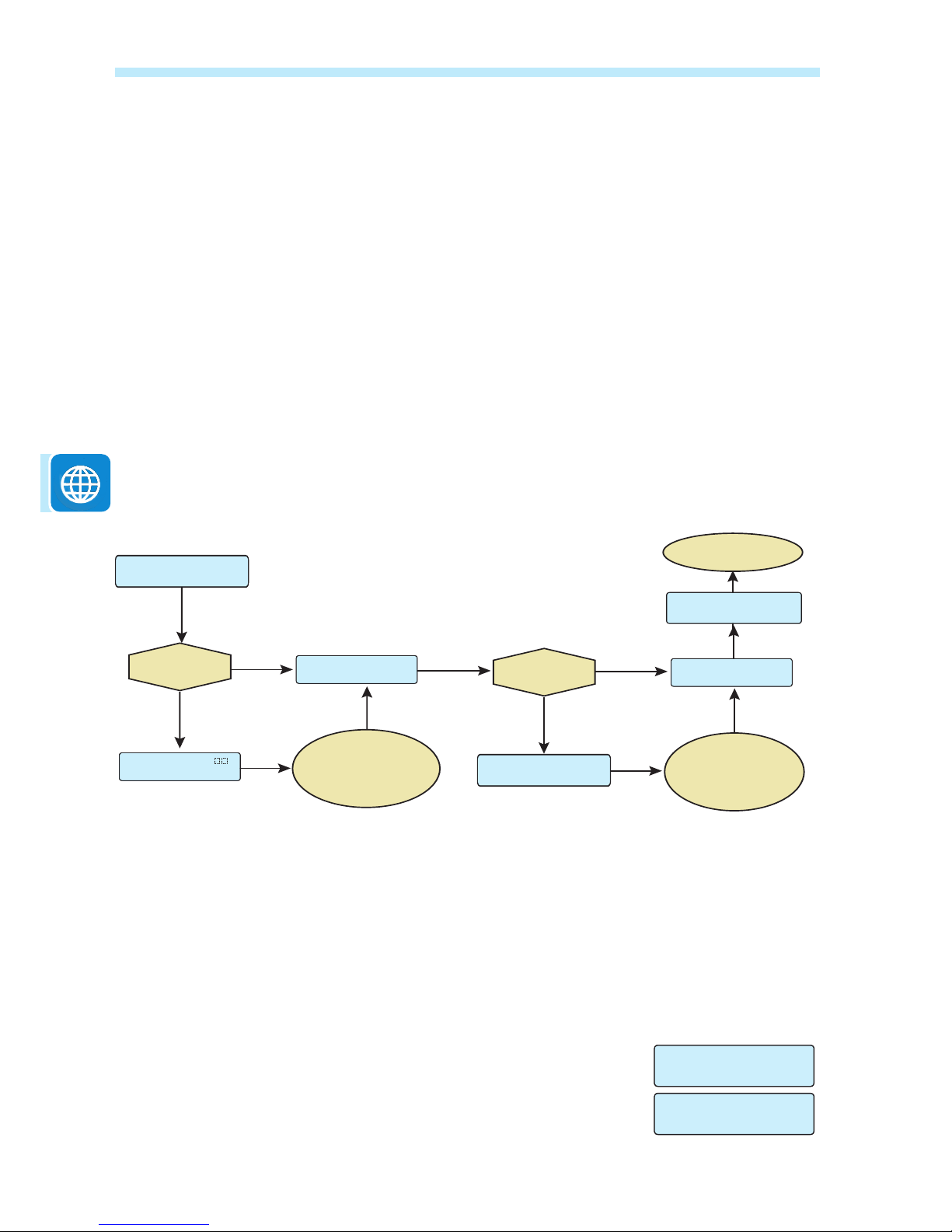
The continuation of the installation differs depending on the type of protection of the selected network (Open,
WPA/WPA2). If no wireless networks are found, it may be necessary to change the DHCP settings, (page 24.)
Open networks with a MAC address filter
The MAC address is used to set up the conguration menu of the router which is not supplied
by ABB. Refer to documentation from the manufacturer of the router for instructions to add
the CDD to the list of enabled MAC addresses on the router.
The MAC address can be found on the CDD product label as illustrated on page 8 and is
used to congure the router prior to connection. If the router has not been congured, the
MAC address will be displayed during the connection procedure as follows:
• The CDD will start the connection as shown above.
• The connection is refused and a Fail message is displayed.
• The WiFi MAC address of the CDD is displayed.
Once the router is congured, power down the CDD to restart the
conguration procedure outlined above.
Installation
WiFi Scanning
Insert Passkey
More than one
network found?
Press ESC to exit
the menu
Scroll UP/DOWN to
view list of networks,
press ENTER to
select
OPEN
Network?
NO
NO
YES
YES
Connecting to
WLess [XX] Done!
Connecting to
WLess [XX]
[XX] Open [ ]
House ....
ENTER passkey
and press ENTER
twice to connect
WLess enabled
YES >
Connecting to
WLess [XX] Fail!
MAC Address
A052725AF5222 >
 Loading...