

Page 1
Application examples
C6701
Electronic
Safety relays
7
Application
The C 6701 safety combination can be used in EMERGENCY STOP circuits
according to EN 418 and in safety circuits according to
EN 60 204-1 (11.98), e.g. in movable guards and safety gates.
Depending on the external circuit elements, safety category 4 according to DIN
EN 954-1 or SIL 3 according to IEC 61508 can be achieved.
Functions and connections
The C 6701 safety combination has two reliable solid-state outputs. Three LEDs
indicate the operating state and the function.
When the device is put into operation it runs through a self-test to test the
correct functioning of the internal electronics. All internal circuit components are
monitored for faults cyclically during operation.
The EMERGENCY STOP button and /or the position switches or light arrays are
connected to terminals Y11, Y12 and Y21, Y22. The ON button is connected in
series with the NC contacts of the external actuators to the supply voltage L+ (24
V DC) and to terminal Y34. The cascading input 1 is connected either via a safe
output or directly to the supply voltage L+ (24 V DC).
External actuators or loads can be switched via safe outputs 14, 24.
It must be ensured that the actuators or loads and the C 6701 electronic safety
combination have the same frame potential. Paralleling outputs 14 and 24 to
increase the load current is not permissible.
If electronic sensors (e.g. light-array monitoring) are used, in
single-channel operation, Y35 must be connected to L+ (24VDC).
For autostart operation, Y32 must be connected directly to L+ (24VDC) and Y34
must be connected to it via NC contacts of the external actuators.
Use a power pack to IEC 60536 safety class III (SELV or
PELV) for power supply!
Terminal marking
Supply voltage A1 L/+
A2 M
Inputs Y11, 12 Channel 1 EMERGENCY STOP or
position switch
Y21, 22 Channel 2 EMERGENCY STOP or
position switch
Y35 With / without cross circuit detection
Y32 Autostart switch
Y34 ON button, feedback loop
Input 1 Cascading input
Outputs 14, 24 Safe solid state outputs
Internal circuit
(+)
Y11
A1
6,3 A
A2
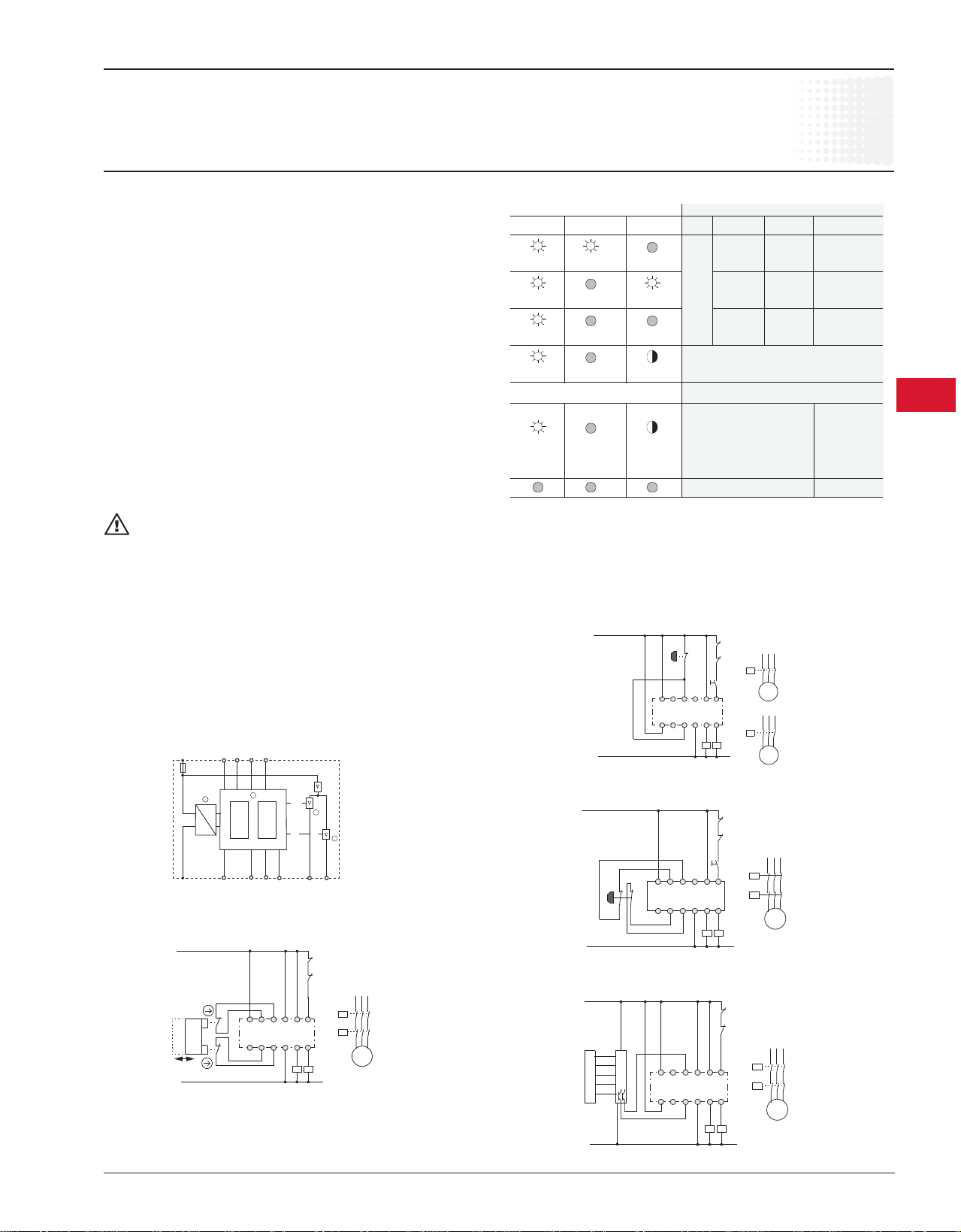
Safety gate monitoring, two channel, autostart
Category 4/SIL 3
M
1 Sensor circuits open; Cross circuit between the sensors; Short circuit of sensors to frame
2 Only when using circuit variant with "cross circuit detection".
Y35Y21 Y32
11
µC1 µC2
Y12(-) Y22 Y34 24141
C6701
2
A1L+Y32 1 Y34
Y11
Y12
A2
Y21Y35
Y22
14 24
K1
K2
1 Power pack
2 Sensors
3 Output 1
4 Output 2
3
4
K1
K2
K1
K2
M
Operation
LEDs Operation
POWER RUN FAIL PS E-STOP ON Outputs
ON non activated on
activated
activated non off
1) activated
non non off
activated activated
on start up self test approx. 7 sec.
fl ashes
Fault
Defect in the electronic off
Change in terminal
fl ashes assignment during
operation
Short circuit to 24V
No supply voltage
Fault clearance
1. Switch supply voltage off.
2. Clear fault or replace device.
3. Switch supply voltage back on.
Cable length
for 2 x 1.5mm2 max. 2000m total cable length for
150nF/km sensors
EMERGENCY STOP, single channel, monitored start
Category 2/SIL 1
K1
K2
A1L+Y32 1 Y34
Y11
C6701
Y21Y35
M
EIN
Y12
A2
Y22
14 24
K1
K2
EMERGENCY STOP, two channel, monitored start with additional
ON button category — Category 4/SIL3
K1
K2
EIN
A1L+Y32 1 Y34
Y11
Y12
C6701
A2
Y21Y35
Y22
M
K1
K2
14 24
K1
K2
Light array monitoring, two channel, autostart category,
Category 4/SIL3
L+
A1
Y11
C6701
Y21Y35
M
Y12
Y22
Y32 1 Y34
A2
14 24
K1
K2
K1
K2
2)
K1
M
K2
M
M
K1
K2
M
7
Low Voltage Products & Systems 7.35
AC 1000 - 11/03
 Loading...