

Page 1
Electronic
M
14 24
K2
A2
K1
M
A1
L+
EIN
EMERGENCY-STOP
Y34
K1
K2
Y21Y20
Y11
Y22
Y12
K1 K2
C6700
EIN
MM
K2K1
Y11
14 24
K2
A2Y21Y20 Y22
K1
M
A1 Y12
L+
Y34
K1 K2
EMERGENCY-STOP
7
Safety relays
Application examples
C6700
Applications
The C 6700 safety combination can be used in EMERGENCY STOP circuits according to EN 418 and in safety circuits according to
EN 60 204-1 (11.98), e.g. for moving covers and safety gates.
Safety catetory 3 according to DIN EN 954-1 or SIL2 according to
IEC 61508 can be achieved, depending on the external circuits.
Functions and connections
The C 6700 safety relay has two solid-state outputs. Three LEDs indicate the
operating state and the function. During operation, all internal circuit elements
are cyclically monitored for faults.
The EMERGENCY STOP button or the position switch are connected to terminals Y11, 12 or Y21, 22. The ON button is connected in series to the NC contacts
of the external actuators (feedback loop) to terminals Y33, 34 .
The C 6700 safety relay and the activated contactors K1 and K2 must have the
same frame potential. Safety category 3 to EN 954-1 is achieved only in combination with 2 external actuators with positively driven feedback contacts.
7
Use a power pack to IEC 60536 safety class III (SELV or
PELV) for power supply!
Terminal marking
Supply voltage A1 L/+
A2 M
Inputs Y11, 12 Channel 1 EMERGENCY STOP
or position switch
Y21, 22 Channel 2 EMERGENCY STOP
or position switch
Y20 Single channel switch
Y33, 34 ON button, feedback loop
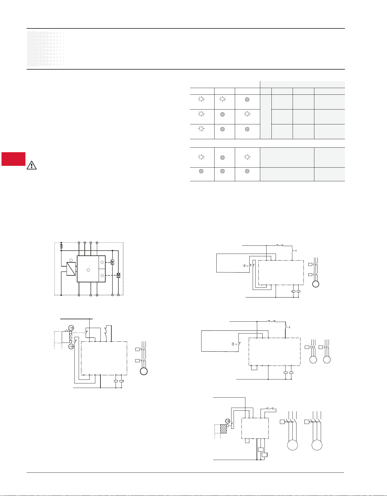
Operation
LEDs Operation
POWER RUN FAIL PS E-STOP ON Outputs
ON non activated on
activated
activated non off
activated
non non off
activated activated
Faults
• Defect in electronic off
• Crossover in
EMERGENCY STOP circ.
No supply voltage
Fault clearance
1. Switch supply voltage off.
2. Clear fault or replace device.
3. Switch supply voltage back on.
Cable length
for 2 x 1.5mm
150nF/k m sensor s
2
max. 2000m total cable length for
Outputs 14, 24 Solid-state outputs
Internal circuit EMERGENCY STOP, single channel, with monitored start
(+)
Y11
A1
2.5 A
Y21Y20 Y33
1
3
2
4
1 Power pack
2 Control logic
3 Output 1
4 Output 2
Category 3/SIL2
Y12(-) Y22 Y34 2414
A2
Two channel autostart for safety gate monitoring
Category 3/SIL2
L/+
K1
K2
A1
Y33 Y34
Y11
Y12
open closed
7.34 Low Voltage Products & Systems
AC 1000 - 11/03
C6700
Y22
A2
14 24
K1
K2
Y21Y20
M
K1
K2
M
EMERGENCY STOP, single channel, with monitored start
Category 2/SIL1
Single channel autostart for safety gate monitoring
Category 2/SIL1
K1 K2
Y11
Y12
A1L+Y33 Y34
K2
MM
open closed
M
C6700
K1
A2
Y21Y20
Y22
14 24
K1
K2
 Loading...