

Page 1
AF400 … AF2650 3-pole contactors
Technical data
Main pole - Utilization characteristics according to IEC
Contactor types
Standards IEC 60947-1 / 60947-4-1 and EN 60947-1 / 60947-4-1
1
Rated operational voltage Ue max. 1000 V
Rated frequency (without derating) 50/60 Hz
Conventional free-air thermal current Ith
acc. to IEC 60947-4-1, open contactors,
2
With conductor cross-sectional area (3)
AC-1 Utilization category
For air temperature close to contactor
Ie / Rated operational current AC-1
Ue max. ≤ 690 V, 50/60 Hz
Ie / Rated operational current AC-1
Ue max. ≤ 1000 V, 50/60 Hz
With conductor cross-sectional area
AC-3 Utilization category
For air temperature close to contactor θ ≤ 55 °C
Ie / Max. rated operational current AC-3 (1)
M
3-phase motors
3
Rated operational power AC-3 (1)
1500 r.p.m. 50 Hz
M
1800 r.p.m. 60 Hz
3-phase motors
3
Rated making capacity AC-3 10 x Ie AC-3 acc. to IEC 60947-4-1
Rated breaking capacity AC-3 8 x Ie AC-3 acc. to IEC 60947-4-1
Short-circuit protection device for contactors
without thermal overload relay
Motor protection excluded (2)
Ue ≤ 500 V AC - gG type fuse 630 A 800 A 1000 A 1000 A Please consult us for coordination with circuit-breaker
Rated short-time withstand current Icw
at 40 °C ambient temperature,
in free air from a cold state
Maximum breaking capacity
cos φ = 0.45
(cos φ = 0.35 for Ie > 100 A)
Power dissipation per pole
Max. electrical switching
frequency
(1) For the corresponding kW/A or hp/A values of 1500 r.p.m, 50 Hz or 1800 r.p.m, 60 Hz, 3-phase motors, see "Motor rated operational powers and currents".
(2) For the protection of motor starters against short circuits, see "Coordination with short-circuit protection devices".
(3) Conductors with preparation.
(4) Max. connection bar width 50 mm.
(5) Max. connection bar width 100 mm.
AC / DC operated
θ
≤ 40 °C
θ
≤ 40 °C
θ
≤ 55 °C
θ
≤ 70 °C
θ
≤ 40 °C
θ
≤ 55 °C
θ
≤ 70 °C
220-230-240 V
380-400 V
415 V
440 V
500 V
690 V
1000 V
220-230-240 V
380-400 V
415 V
440 V
500 V
690 V
1000 V
1 s
10 s
30 s
1 min
15 min
at 440 V
at 690 V
Ie / AC-1
Ie / AC-3
AC-1
AC-3
AC-2, AC-4
AF400 AF460 AF580 AF750 AF 125 0 AF135 0 AF1650 AF2050 AF2650
600 A 700 A 800 A 1050 A 1260 A 1350 A 1650 A 2050 A 2650 A
2x185 mm² 2x240 mm² 2x240 mm² 800 mm² (4) 1000 mm² (4) 1000 mm² (5) 1500 mm² (5) 2000 mm² (5) 3000 mm² (5)
600 A 700 A 800 A 1050 A 1260 A 1350 A 1650 A 2050 A 2650 A
500 A 600 A 700 A 875 A 1040 A 1150 A 1450 A 1750 A 2350 A
400 A 480 A 580 A 720 A 875 A 1000 A 1270 A 1500 A 2120 A
600 A 700 A 800 A 1000 A 1260 A 1350 A 1650 A 2050 A 2650 A
500 A 600 A 700 A 875 A 1040 A 1150 A 1450 A 1750 A 2350 A
400 A 480 A 580 A 720 A 875 A 1000 A 1270 A 1500 A 2120 A
2x185 mm² 2x240 mm² 2x240 mm² 800 mm² (4) 1000 mm² (4) 1000 mm² (5) 1500 mm² (5) 2000 mm² (5) 3000 mm² (5)
400 A 460 A 580 A 750 A – 860 A 1050 A – –
400 A 460 A 580 A 750 A – 860 A 1050 A – –
400 A 460 A 580 A 750 A – 860 A 1050 A – –
400 A 460 A 580 A 750 A – 860 A 1050 A – –
400 A 460 A 580 A 750 A – 800 A 950 A – –
350 A 400 A 500 A 650 A – 800 A 950 A – –
155 A 200 A 250 A 300 A – – – – –
110 kW 132 kW 160 kW 220 kW – 257 kW 315 kW – –
200 kW 250 kW 315 kW 400 kW – 475 kW 560 kW – –
220 kW 250 kW 355 kW 425 kW – 500 kW 600 kW – –
220 kW 250 kW 355 kW 450 kW – 560 kW 670 kW – –
250 kW 315 kW 400 kW 520 kW – 560 kW 700 kW – –
315 kW 355 kW 500 kW 600 kW – 750 kW 900 kW – –
220 kW 280 kW 355 kW 400 kW – – – – –
4600 A 4600 A 7000 A 7000 A 8000 A 10000 A 12000 A 12000 A 12000 A
4400 A 4400 A 6400 A 6400 A 7200 A 8000 A 10000 A 10000 A 10000 A
3100 A 3100 A 4500 A 4500 A 5200 A 6000 A 7500 A 7500 A 7500 A
2500 A 2500 A 3500 A 3500 A 4000 A 4500 A 5500 A 5500 A 5500 A
840 A 840 A 1300 A 1300 A 1500 A 1600 A 2200 A 2200 A 2800 A
4000 A 5000 A 6000 A 7500 A 10000 A 12000 A 8400 A 8400 A
3500 A 4500 A 5000 A 7000 A – – – –
30 W 42 W 32 W 50 W 80 W 80 W 80 W 125W 200 W
16 W 21 W 17 W 28 W – 50 W 50 W – –
300 cycles/h 300 cycles/h 300 cycles/h 60 cycles/h 60 cycles/h 15 cycles/h
300 cycles/h 300 cycles/h – 60 cycles/h – –
60 cycles/h 60 cycles/h – 60 cycles/h – –
2.64 | Motor protection and control Motor protection and control | 2.65
2.64 | Motor protection and control Motor protection and control | 2.65
Page 2
AF400 ... AF2650 3-pole contactors
B2
Technical data
Main pole - Utilization characteristics according to UL / NEMA / CSA
Contactor types
1
Standards UL 60947-1 / 60947-4-1A and CSA 60947-1 / 60947-4-1A
Maximum operational voltage 600 V 1000 V
NEMA size – 6 – 7 – 8 – –
NEMA maximum horse power ratings
2
1-phase, 60 Hz
NEMA maximum horse power ratings
3-phase, 60 Hz
UL / CSA general use rating
600 V AC 550 A 650 A 750 A 900 A 1210 A 1350 A 1650 A 2100 A 2700 A
UL / CSA maximum 1-phase motor rating
Full load current
Horse power rating
UL / CSA maximum 3-phase motor rating
Full load current (1)
Horse power rating (1)
Short-circuit protection device for contactors
without thermal overload relay - Motor protection excluded
Fuse rating 1000 A 1200 A Please consult us for coordination with
Fuse type, 600 V L
Maximum electrical switching frequency
For general use 300 cycles/h 60 cycles/h 15 cycles/h
For motor use 300 cycles/h 60 cycles/h –
(1) For the corresponding kW/A or hp/A values of 1500 r.p.m, 50 Hz or 1800 r.p.m, 60 Hz, 3-phase motors, see “Motor rated operational powers and currents”.
AC / DC operated
115 V AC
230 V AC
200 V AC
230 V AC
460 V AC
575 V AC
120 V AC
240 V AC
120 V AC
240 V AC
200-208 V AC
220-240 V AC
440-480 V AC
550-600 V AC
200-208 V AC
220-240 V AC
440-480 V AC
550-600 V AC
AF400 AF460 AF580 A F750 A F125 0 AF135 0 AF16 50 AF2050 AF2650
–
–
– 150 hp – – – – – –
– 200 hp – 300 hp – 450 hp – –
– 400 hp – 600 hp – 900 hp – –
– 400 hp – 600 hp – 900 hp – –
– – – – – – – – –
– – – – – – – – –
– – – – – – – – –
– – – – – – – – –
358.8 A 414 A 552 A 692.3 A – 954 A 1030 A – –
360 A 480 A 604 A 722 A – 954 A 1030 A – –
414 A 477 A 590 A 722 A – 954 A 1030 A – –
382 A 472 A 578 A 672 A – 944A 1050 A – –
125 hp 150 hp 200 hp 250 hp – – – – –
150 hp 200 hp 250 hp 300 hp – 400 hp 450 hp – –
350 hp 400 hp 500 hp 600 hp – 800 hp 900 hp – –
400 hp 500 hp 600 hp 700 hp – 1000 hp 1150 hp – –
circuit-breaker
General technical data
Contactor types
Rated insulation voltage Ui
acc. to IEC 60947-4-1 1000 V
acc. to UL 600 V 1000 V
Rated impulse withstand voltage Uimp. 8 kV
Electromagnetic compatibility AF contactors complying with IEC 60947-1 / EN 60947-1 - Environment A
Ambient air temperature close to contactor
Operation Fitted with electronic overload relay -25 to +70 °C
Without electronic overload relay -40 to +70 °C
Storage -40 to +70 °C
Maximum operating altitude (without derating) 3000 m
Mechanical durability
Number of operating cycles 3 millions operating cycles 0.5 million operating cycles 0.3 million
Max. switching frequency 300 cycles/h 60 cycles/h
Shock withstand
acc. to IEC 60068-2-27 and EN 60068-2-27
Mounting position 1
C1
ABB
A
2.68 | Motor protection and control Motor protection and control | 2.69
2.68 | Motor protection and control Motor protection and control | 2.69
B1
A
C2
AC / DC operated
Shock direction
A
B1
B2
C1
C2
AF400 AF460 AF580 A F750 A F125 0 AF135 0 AF16 50 AF2050 AF2650
operating
cycles
1/2 sinusoidal shock for 30 ms: no change in contact position, closed or open position
5 g –
5 g –
5 g –
5 g –
5 g –
Page 3

AF400 ... AF2650 3-pole contactors
Pos. 5
Pos. 6
Pos. 2
Pos. 1 Pos. 1 ± 30°
+30° -30°
Po
Technical data
Magnet system characteristics
Contactor types
1
Coil operating limits
acc. to IEC 60947-4-1
Rated control circuit voltage Uc
Coil consumption
2
AC control voltage 50/60 Hz
24...60 V AC
48...130 V AC
100...250 V AC
250 … 500 V AC
DC control voltage
20...60 V DC
48...130 V DC
100...250 V DC
250 … 500 V AC
Drop-out voltage 55 % of Uc min.
Voltage sag immunity Conditions of use on request
acc. to SEMI F47
Dips withstand ≥ 20 ms
Operating time
Coil supply between A1 - A2
Between coil energization and:
Between coil de-energization and:
Control input for PLC's
Between coil energization and:
Between coil de-energization and:
AC / DC operated
AC supply
DC supply
Average pull-in value
Average holding value
Average pull-in value
Average holding value
Average pull-in value
Average holding value
Average pull-in value
Average holding value
Average pull-in value
Average holding value
Average pull-in value
Average holding value
Average pull-in value
Average holding value
Average pull-in value
Average holding value
Main contact closing
Main contact opening
Main contact closing
Main contact opening
AF400 AF460 AF580 AF750 AF12 50 AF135 0 AF 1650 AF2050 AF2650
At θ ≤ 70°C 0.85 x Uc min ... 1.1 x Uc max
At θ ≤ 70°C 0.80 x Uc min ... 1.1 x Uc max
900 VA 780 VA 12 VA 12 VA 1215 VA 1100 VA 12 VA 12 VA 955 VA 880 VA 2450 VA
12 VA 12 VA 48 VA
950 VA 985 VA 12 VA 12 VA -
900 VA 785 VA 5 VA 5.5 VA 1150 VA 1020 VA 5 VA 5 VA 895 VA 880 VA 2290 VA
5 VA 5 VA 20.5 VA
885 VA 910 VA -
7.5 VA 7.5 VA -
50…120 ms 50…80 ms
33…70 ms 35…55 ms
40…60 ms 40...90 ms 40…65 ms
10…30 ms 10…30 ms
Mounting characteristics and conditions for use
Contactor types
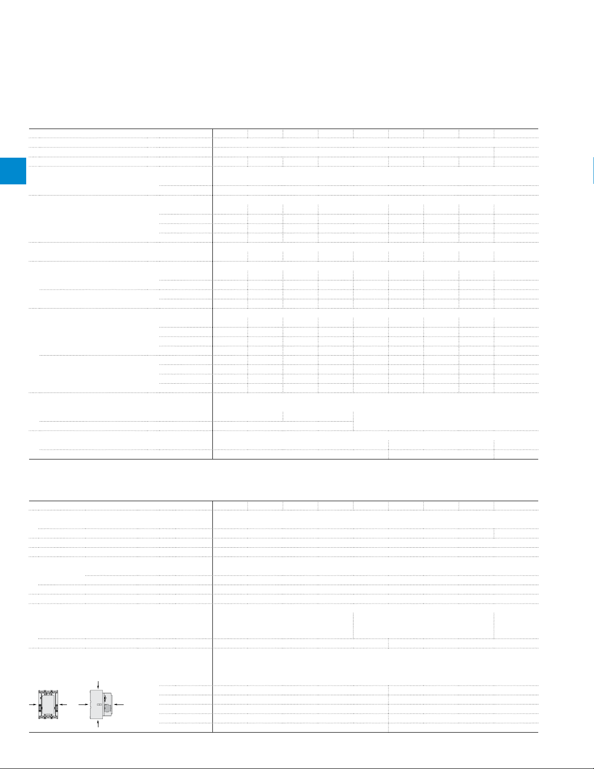
Mounting positions
Mounting distances The contactors can be assembled side by side
Fixing
On rail according to IEC 60715, EN 60715 –
By screws (not supplied) 4 x M5 4 x M6 4 x M8
2.72 | Motor protection and control Motor protection and control | 2.73
2.72 | Motor protection and control Motor protection and control | 2.73
AC / DC operated
AF400 AF460 AF580 AF750 AF 1250 A F13 50 A F16 50 AF2050 AF2650
s. 4
Max. add-on N.O. or N.C. auxiliary contacts: see accessory fitting details for 3-pole contactor
AF400 ... AF2650
Pos. 3
Page 4

AF400 ... AF2650 3-pole contactors
ø 10.525ø 6.5
22.5
50
ø 12.5
40
ø 6.5
80
10 (AF2050)
25 (AF2650)
ø 13
80
10
L
L
Technical data
Connecting characteristics
Contactor types
1
Main terminals
Flat type
2
Connection capacity (min. ... max.)
Main conductors (poles)
Connection capacity acc. to UL / CSA
Connection capacity acc. to UL / CSA
Auxiliary conductors
(coil terminals)
Connection capacity acc. to UL / CSA
Tightening torque Recommended 1.00 Nm / 9 lb.in
Degree of protection
acc. to IEC 60947-1 / EN 60947-1 and IEC 60529 / EN 60529
Main terminals IP00
Coil terminals IP20
Screw terminals
Main terminals M10 M12
Coil terminals (delivered in open position) M3.5
Cu cable - Stranded
Clamp type 1SDA013922R1 –
Tightening torque 35 Nm –
Cu cable - Stranded
Clamp type – 1SDA013956R1 –
Tightening torque 35 Nm 45 Nm –
Al cable - Stranded
Clamp type 1SDA013922R1 –
Tightening torque 35 Nm –
Clamp type – 1SDA013956R1 –
Tightening torque 35 Nm 45 Nm –
Lugs
ø
Tightening torque 35 Nm / 310 Ib.in 45 Nm / 398 lb.in
Clamp type K6TH alt. ATK580 – bars, use
Tightening torque 275 Ib.in –
Clamp type
Tightening torque 275 Ib.in 375 Ib.in 500 Ib.in –
Solid / stranded
Flexible
Flexible with non insulated ferrule
Flexible with insulated ferrule
Lugs
l
Max. 1.20 Nm
AC / DC operated
2 x
3 x
2 x
3 x
W ≤
Ø >
2 x
3 x
1 x
2 x
1 x
2 x
1 x
2 x
1 x
2 x
L ≤
l >
1 or 2 x
Screwdriver type
AF400 AF460 AF580 AF750 AF1250 AF1350 AF165 0 AF2050 AF2650
6
240 mm² –
– 185 mm² –
240 mm² –
– 185 mm² –
47 mm 50 mm 100 mm
10 mm 12 mm
250-500 MCM alt. 2/0
AWG-400 MCM
2/0 AWG-400 MCM 2/0 AWG-500 MCM 1/0-750 MCM –
K6TJ ATK750/3
1...4 mm²
1...4 mm²
0.75...2.5 mm²
0.75...2.5 mm²
0.75...2.5 mm²
0.75...2.5 mm²
0.75...2.5 mm²
0.75...2.5 mm²
8 mm
3.7 mm
AWG 18...14
Screws and bolts
Flat Ø 5.5 mm / Pozidriv 2
27
8
22.5
6
AF750
ø 13
AF1250AF580
– 2// 3 x
0.25 in
LW1250
40
27
25 15.5
17
30
10
AF1350
AF1650
4/0 AWG - 500 MCM 4//4 x 0.25 in
K7TK
K7TK bars
ATK1350/4
375 Ib.in
K8TL,
K8TM,
ATK1650/4
K8TL,
K8TM,
ATK1650/4,
–
–
ATK1650/6
40
AF2050
AF2650
17
40
2.76 | Motor protection and control Motor protection and control | 2.77
2.76 | Motor protection and control Motor protection and control | 2.77
 Loading...