

Page 1

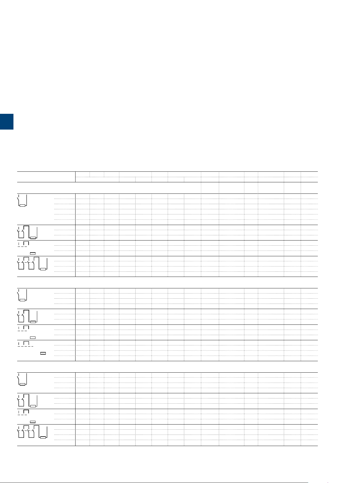
AF09(Z)B ... AF38(Z)B 3-pole contactors
Technical data
Main pole - Utilization characteristics according to IEC
Contactor types
Standards
Fire and smoke
Rated operational voltage Ue max.
Rated frequency (without derating)
Conventional free-air thermal current Ith
acc. to IEC 60947-4-1, open contactors, θ ≤ 40°C
3
With conductor cross-sectional area
AC-1 Utilization category
For air temperature close to contactor
Ie / Rated operational current AC-1
Ue max. ≤ 690V, 50/60Hz
With conductor cross-sectional area
AC-3 Utilization category
For air temperature close to contactor θ ≤ 60°C
Ie / Max. rated operational current AC-3 (1)
M
3-phase motors
θ ≤ 40°C
θ ≤ 60°C
θ ≤ 70°C
220-230-240V
380-400V
3
Rated operational power AC-3 (1)
1500 r.p.m. 50Hz
M
1800 r.p.m. 60Hz
3
Rated making capacity AC-3
Rated breaking capacity AC-3
Short-circuit protection device for contactors
without thermal overload relay - Motor protection excluded (2)
Ue ≤ 500V AC - gG type fuse
Rated short-time withstand current Icw 1s
at 40°C ambient temperature, 10s
in free air from a cold state 30s
Maximum breaking capacity
cos φ = 0.45
Power dissipation per pole Ie / AC-1
Max. electrical switching frequency AC-1
(1) For the corresponding kW/A or hp/A values of 1500 r.p.m, 50Hz or 1800 r.p.m, 60Hz, 3-phase motors, see "Motor rated operational powers and currents".
(2) For the protection of motor starters against short circuits, see "Coordination with short-circuit protection devices".
3-phase motors
220-230-240V
380-400V
at 440V
at 690V
Ie / AC-3
AF09(Z)B AF 12( Z)B AF16(Z) B AF26(Z)B AF30(Z)B AF38(Z)B
IEC 60947-1 / 60947-4-1 and EN 60947-1 / 60947-4-1
IEC 60077-1, IEC 60077-2, EN 50155 (applicable parts)
EN 45545 (HL2, HL3)
690 V
50 / 60 Hz
35 A 35 A 35 A 50 A 50 A 50 A
6 mm² 6 mm² 6 mm² 10 mm² 10 mm² 10 mm²
25 A 28 A 30 A 45 A 50 A 50 A
25 A 28 A 30 A 40 A 42 A 42 A
22 A 24 A 26 A 32 A 37 A 37 A
4 mm² 6 mm² 6 mm² 10 mm² 10 mm² 10 mm²
9 A 12 A 18 A 26 A 33 A 40 A
9 A 12 A 18 A 26 A 32 A 38 A
415V
9 A 12 A 18 A 26 A 32 A 38 A
440V
9 A 12 A 18 A 26 A 32 A 38 A
500V
9.5 A 12.5 A 15 A 23 A 28 A 33 A
690V
7 A 9 A 10.5 A 17 A 21 A 24 A
2.2 kW 3 kW 4 kW 6.5 kW 9 kW 11 kW
4 kW 5.5 kW 7.5 kW 11 kW 15 kW 18.5 kW
415V
4 kW 5.5 kW 9 kW 11 kW 15 kW 18.5 kW
440V
4 kW 5.5 kW 9 kW 15 kW 18.5 kW 22 kW
500V
5.5 kW 7.5 kW 9 kW 15 kW 18.5 kW 22 kW
690V
5.5 kW 7.5 kW 9 kW 15 kW 18.5 kW 22 kW
10 x Ie AC-3 acc. to IEC 60947-4-1
8 x Ie AC-3 acc. to IEC 60947-4-1
25 A 32 A 32 A 50 A 63 A 63 A
300 A 300 A 300 A 700 A 700 A 700 A
150 A 150 A 150 A 350 A 350 A 350 A
80 A 80 A 80 A 225 A 225 A 225 A
1 min
60 A 60 A 60 A 150 A 150 A 150 A
15 min
35 A 35 A 35 A 50 A 50 A 50 A
250 A 250 A 250 A 500 A 500 A 500 A
106 A 106 A 106 A 200 A 200 A 200 A
0.8 W 1 W 1.2 W 1.8 W 2.4 W 2.4 W
0.1 W 0.2 W 0.35 W 0.6 W 0.9 W 1.3 W
600 cycles/h
AC-3
1200 cycles/h
AC-4
300 cycles/h 150 cycles/h
162 | ABB
1SBC100115S0201
Page 2

AF09(Z)B ... AF38(Z)B 3-pole contactors
Technical data
Main pole - Utilization characteristics according to UL / NEMA / CSA
Contactor types
Standards
Maximum operational voltage
NEMA size
NEMA continuous amp rating Thermal current
NEMA maximum horse power ratings
1-phase, 60Hz
NEMA maximum horse power ratings
3-phase, 60Hz
UL / CSA general use rating
With conductor cross-sectional area
UL / CSA maximum 1-phase motor rating
Full load current 120V AC
Horse power rating 120V AC
UL / CSA maximum 3-phase motor rating
Full load current (1) 200-208V AC
Horse power rating (1) 200-208V AC
Short-circuit protection device for contactors
without thermal overload relay - Motor protection excluded
Fuse rating
Fuse type, 600V
Maximum electrical switching frequency
For general use
For motor use
(1) For the corresponding kW/A or hp/A values of 1500 r.p.m, 50 Hz or 1800 r.p.m, 60 Hz, 3-phase motors, see “Motor rated operational powers and currents”.
115V AC
230V AC
200V AC
230V AC
460V AC
575V AC
600V AC
240V AC
240V AC
220-240V AC
440-480V AC
550-600V AC
220-240V AC
440-480V AC
550-600V AC
AF0 9( Z)B A F12(Z) B
UL 508, CSA C22.2 N°60947-4-1
600 V
00
9 A
1/3 hp
1 hp
1-1/2 hp
1-1/2 hp
2 hp
2 hp
25 A
AWG 10
13.8 A
10 A
3/4 hp
1-1/2 hp
7.8 A
6.8 A
7.6 A
9 A
2 hp
2 hp
5 hp
7-1/2 hp
30 30
J
600
1200
0
18 A
1 hp
2 hp
3 hp
3 hp
5 hp
5 hp
28 A
AWG 10
16 A
12 A
1 hp
2 hp
11 A
9.6 A
11 A
11 A
3 hp
3 hp
7-1/2 hp
10 hp
AF16(Z) B
–
30 A
AWG 10
20 A
17 A
1-1/2 hp
3 hp
17.5 A
15.2 A
14 A
17 A
5 hp
5 hp
10 hp
15 hp
60
AF26(Z)B
1
27 A
2 hp
3 hp
7-1/2 hp
7-1/2 hp
10 hp
10 hp
45 A
AWG 8
24 A
17 A
2 hp
3 hp
25.3 A
22 A
21 A
22 A
7-1/2 hp
7-1/2 hp
15 hp
20 hp
60
AF30(Z)B AF38(Z)B
– –
50 A
AWG 8
24 A
28 A
2 hp
5 hp
32.2 A
28 A
27 A
27 A
10 hp
10 hp
20 hp
25 hp
100 100
50 A
AWG 8
24 A
28 A
2 hp
5 hp
32.2 A
28 A
34 A
32 A
10 hp
10 hp
25 hp
30 hp
3
ABB | 165
11SSBBCC110001011166SS00220101
Page 3

AF09(Z)B ... AF38(Z)B 3-pole contactors
Pos. 2
-30°
Technical data
General technical data
Contactor types
Rated insulation voltage Ui
acc. to IEC 60947-4-1 690 V
acc. to UL / CSA 600 V
Rated impulse withstand voltage Uimp. 6 kV
Electromagnetic compatibility Devices complying with IEC 60947-1 / EN 60947-1 - Environment A
Ambient air temperature close to contactor
3
Operation Fitted with thermal overload relay -20...+60 °C
Storage -60...+80 °C
Climatic withstand Category B according to IEC 60947-1 Annex Q
Maximum operating altitude (without derating) 3000 m
Mechanical durability
Number of operating cycles 10 millions operating cycles
Maximum switching frequency 3600 cycles/h
Shock and vibration withstand
acc. to IEC 61373 Category 1, class B
Without thermal overload relay -40...+70 °C
Magnet system characteristics
Contactor types
Coil operating limits DC supply
acc. to IEC 60947-4-1
DC control voltage
Rated control circuit voltage Uc
Coil consumption
PLC-output control
AC control voltage 50/60 Hz
Rated control circuit voltage Uc
Coil consumption
Max. permitted control voltage
during voltage fluctuation defined
acc. to IEC 60077 / EN 50155
Drop-out voltage
Operating time
Between coil energization and: N.O. contact closing
Between coil de-energization and: N.O. contact opening
Average pull-in value
Average holding value
Average pull-in value
Average holding value
N.C. contact opening
N.C. contact closing
AC supply
AF09(Z)B AF 12( Z)B AF16(Z) B AF26(Z)B AF30(Z)B AF38(Z)B
EN 50121-3-2
AF09(Z)B AF 12( Z)B AF16(Z) B AF26(Z)B AF30(Z)B AF38(Z)B
(AF..ZB) at θ ≤ 70 °C 0.85 x Uc min ... 1.1 x Uc max
(AF..B) at θ ≤ 60 °C 0.85 x Uc min ... 1.1 x Uc max; at θ ≤ 70 °C 0.85 x Uc min ... Uc max
at θ ≤ 60 °C 0.85 x Uc min ... 1.1 x Uc max
at θ ≤ 70 °C 0.85 x Uc min ... Uc max
20 ... 250 V DC
(AF..Z) 12 ... 16 W
(AF..Z) 1.7 W
(AF..Z) ≥ 500 mA 24 V DC
(AF..ZB) 24 ... 250 V AC - (AF..B) 250 ... 500 V AC
(AF..ZB) 16 VA - (AF..B) 50 VA
(AF..ZB) 1.7 VA / 1.5 W - (AF..B) 2.2 VA / 2 W
Rated control circuit voltage / Max. permitted control voltage
24 ... 60 V AC 50/60 Hz / 75 V AC 50/60 Hz
48 ... 130 V AC 50/60 Hz / 150 V AC 50/60 Hz
100 ... 250 V AC 50/60 Hz / 275 V AC 50/60 Hz
250 ... 500 V AC 50/60 Hz / 550 V AC 50/60 Hz
≤ 60 % of Uc min.
40...95 ms
38...90 ms
11...95 ms
13...98 ms
Mounting characteristics and conditions for use
Contactor types
Mounting positions
Mounting distances
Fixing
On rail according to IEC 60715, EN 60715
By screws (not supplied)
168 | ABB
AF09(Z)B AF 12( Z)B AF16(Z) B AF26(Z)B AF30(Z)B AF38(Z)B
Pos. 4
Max. N.C. built-in add add-on N.C. auxiliary contacts:
see accessory fitting details for a 3-pole contactor AF09(Z)B ... AF38(Z)B
The contactors can be assembled side by side
35 x 7.5 mm or 35 x 15 mm
2 x M4 screws placed diagonally
Pos. 1
Pos. 3
Pos. 1 - 30°
Pos. 5
1SBC100117S0201
Page 4

AF09(Z)B ... AF38(Z)B 3-pole contactors
L
6
L
6
Technical data
Connecting characteristics
Contactor types
Main terminals
AF09(Z)B AF 12( Z)B AF16(Z) B AF26(Z)B AF30(Z)B AF38(Z)B
Connection capacity (min. ... max.)
Main conductors (poles)
Rigid Solid (≤ 4 mm²)
Stranded (≥ 6 mm²)
Flexible with non insulated ferrule
Flexible with insulated ferrule
Bars or lugs L <
Connection capacity acc. to UL/CSA
Stripping length
Tightening torque
Auxiliary conductors
(built-in auxiliary terminals + coil terminals)
Rigid solid
Flexible with non insulated ferrule
Flexible with insulated ferrule
Lugs L <
Connection capacity acc. to UL/CSA
Stripping length
Tightening torque
Coil terminals
Built-in auxiliary terminals
Degree of protection
acc. to IEC 60947-1 / EN 60947-1 and IEC 60529 / EN 60529
Main terminals
Coil terminals
Built-in auxiliary terminals
Screw terminals
Main terminals
Screwdriver type
Coil terminals
Screwdriver type
Built-in auxiliary terminals
Screwdriver type
Screw terminals with cable clamp
1 x
1...6 mm² 2.5...10 mm²
2 x
1...6 mm² 2.5...10 mm²
1 x
0.75...6 mm² 1.5...10 mm²
2 x
0.75...6 mm² 1.5...10 mm²
1 x
0.75...4 mm² 1.5...10 mm²
2 x
0.75...2.5 mm² 1.5...4 mm²
9.6 mm 12.5 mm
1 or 2 x
AWG 16...10 AWG 14...18
10 mm 14 mm
1.5 Nm / 13 lb.in 2.5 Nm / 22 lb.in
1 x
1...2.5 mm²
2 x
1...2.5 mm²
1 x
0.75...2.5 mm²
2 x
0.75...2.5 mm²
1 x
0.75...2.5 mm²
2 x
0.75...1.5 mm²
8 mm
1 or 2 x
AWG 18...14
10 mm
1.2 Nm / 11 Ib.in
1.2 Nm / 11 Ib.in –
IP20
IP20
IP20 –
Delivered in open position, screws of unused terminals must be tightened
M3.5 M4
Flat Ø 5.5 / Pozidriv 2 Flat Ø 6.5 / Pozidriv 2
M3.5
Flat Ø 5.5 / Pozidriv 2
M3.5 –
Flat Ø 5.5 / Pozidriv 2 –
3
1SBC101795S0201 - Rev. A
ABB | 171
Page 5

AF09(Z)B ... AF16(Z)B 3-pole contactors
Technical data
Built-in auxiliary contacts according to IEC
Contactor types
Rated operational voltage Ue max.
Rated frequency (without derating)
Conventional free air thermal current Ith - θ ≤ 40°C
Ie / Rated operational current AC-15
acc. to IEC 60947-5-1 24-127V 50/60Hz
3
Making capacity AC-15
Breaking capacity AC-15
Ie / Rated operational current DC-13
acc. to IEC 60947-5-1 24V DC
Short-circuit protection device gG type fuse
Rated short-time withstand current Icw for 1.0s
Minimum switching capacity
with failure rate acc. to IEC 60947-5-4
Non-overlapping time between N.O. and N.C. contacts
Power dissipation per pole at 6A
Maximum electrical switching frequency AC-15
Mechanically linked contacts
acc. to annex L of IEC 60947-5-1
Mirror contacts
acc. to annex F of IEC 60947-4-1
220-240V 50/60Hz
400-440V 50/60Hz
500V 50/60Hz
690V 50/60Hz
48V DC
72V DC
110V DC
125V DC
220V DC
250V DC
400 V DC
500 V DC
600 V DC
for 0.1s
AF09(Z)B AF 12( Z)B AF16(Z) B
690 V
50 / 60 Hz
16 A
6 A
4 A
3 A
2 A
2 A
10 x Ie AC-15 acc. to IEC 60947-5-1
10 x Ie AC-15 acc. to IEC 60947-5-1
6 A / 144 W
2.8 A / 134 W
1 A / 72 W
0.55 A / 60 W
0.55 A / 69 W
0.27 A / 60 W
0.27 A / 68 W
0.15 A / 60 W
0.13 A / 65 W
0.1 A / 60 W
10 A
100 A
140 A
12 V / 3 mA
-7
10
≥ 2 ms
0.1 W
1200 cycles/h
900 cycles/h
DC-13
Built-in N.O. or N.C. auxiliary contacts and additional N.O. or N.C. auxiliary contacts (CA4, CAL4, CAT4
aux. contact blocks) are mechanically linked contacts.
Built-in N.C. auxiliary contacts or additional N.C. auxiliary contacts (CA4, CAL4, CAT4 aux. contact
blocks) are mirror contacts.
Built-in auxiliary contacts according to UL / CSA
Contactor types
Maximum operational voltage
Pilot duty
AC thermal rated current
AC maximum volt-ampere making
AC maximum volt-ampere breaking
DC thermal rated current
DC maximum volt-ampere making-breaking
174 | ABB
AF09(Z)B AF 12( Z)B AF16(Z) B
600 V AC, 600 V DC
A600, Q600
10 A
7200 VA
720 VA
2.5 A
69 VA
1SBC100118S0201
Page 6
AF09(Z)B ... AF95B contactors
DC circuit switching
General
The arc switching on DC is more difficult than on AC.
– For selecting a contactor it is essential to determine the current, the voltage and the L/R time constant of the controlled load
– For information, typical time constant values are quoted hereafter: non inductive loads such as resistance furnaces (L/R ≈ 1 ms), inductive loads
such as shunt motors (L/R ≈ 2 ms) or series motors (L/R ≈ 7.5 ms)
– The addition of a resistor in parallel with an inductive winding helps in the elimination of the arcs
– All the poles required for breaking must be connected in series between the load and the source polarity not linked to earth (or chassis).
Technical data
3
– The tables indicate for the standard contactors the Ie max. operating currents depending on: the utilization category (i.e. L/R) DC-1, DC-3, DC-5
as defined in the IEC 60947-4-1 publication, the operating voltage Ue and the pole coupling details.
Ampere values quoted in these tables are valid for a -25…+70 °C temperature close to the contactors, as long as these values do not exceed
the AC-1 Ampere values for the corresponding ambient temperature
– Max. switching frequency: 300 cycles/h.
Selection table
Contactor types
AF09 AF12 AF16 AF26 AF30 AF38 AF45 AF50 AF63 AF75 GAF75 AF95
3 or 4-pole 3-pole 4-pole 3-pole 3-pole 4-pole 4-pole
3 or 4-pole 3 or 4-pole 1-pole
3-pole
Utilization category DC-1, L/R ≤ 1 ms
Utilization category DC-3, L/R ≤ 2 ms
≤ 72 V
25 A 27 A 30 A 45 A 45 A 50 A 50 A 55 A 70 A 100 A 110 A 120 A 120 A -
110 V
10 A 15 A 20 A - - - - - - - - - 120 A -
220 V
- - - - - - - - - - - - 120 A -
440 V
- - - - - - - - - - - - 100 A
600 V
- - - - - - - - - - - - 75 A
1000 V
- - - - - - - - - - - - 35 A
≤ 72 V
110 V
220 V
≤ 72 V
110 V
220 V
≤ 72 V
110 V
220 V
440 V
≤ 72 V
110 V
220 V
440 V
≤ 72 V
110 V
220 V
≤ 72 V
110 V
220 V
≤ 72 V
110 V
220 V
440 V
27 A
25 A
27 A
25 A
15 A
10 A
27 A
25 A
27 A
25 A
27 A
25 A
25 A - 30 A - 45 A - - 55 A 70 A 100 A - 120 A - 25 A - 30 A - 45 A - - 55 A 70 A 100 A - 120 A - 25 A - 30 A - 45 A - - 55 A 70 A 100 A - 120 A - 10 A - 20 A - - - - - - - - - - -
27 A
25 A
7 A
6 A
-
-
-
27 A
25 A
27 A
25 A
7 A
6 A
27 A
25 A
27 A
25 A
27 A
25 A
-
25 A
-
25 A
-
25 A
-
6 A
30 A
30 A
20 A
30 A
30 A
30 A
30 A
8 A
-
30 A
30 A
8 A
30 A
30 A
30 A
30 A
30 A
30 A
8 A
45 A
45 A
45 A
45 A
45 A
45 A
-
-
45 A
45 A
45 A
45 A
45 A
-
-
-
-
45 A
45 A
45 A
45 A
45 A
-
-
-
-
-
-
-
-
-
-
-
-
-
-
50 A
50 A
50 A
50 A
50 A
50 A
-
-
50 A
50 A
50 A
50 A
50 A
-
-
-
-
50 A
50 A
50 A
50 A
50 A
50 A
-
-
50 A
50 A
50 A
50 A
50 A
-
-
-
-
55 A
55 A
55 A
55 A
55 A
-
-
-
-
-
-
-
-
-
-
-
-
-
-
70 A
70 A
70 A
70 A
70 A
70 A
-
-
70 A
70 A
70 A
70 A
70 A
70 A
70 A
70
-
100 A
100 A
100 A
100 A
100 A
100 A
-
-
100 A
100 A
100 A
100 A
100 A
100 A
100 A
100 A
-
110 A
110 A
110 A
110 A
110 A
105 A
-
-
110 A
110 A
110 A
110 A
110 A
-
-
-
-
120 A
120 A
120 A
120 A
120 A
125 A
-
-
120 A
120 A
120 A
120 A
120 A
120 A
120 A
120 A
-
-
-
-
-
-
-
120 A
120 A
100 A
85 A
-
-
-
-
-
-
-
-
-
-
145 A
-
145 A
145 A
130 A
-
-
145 A
-
145 A
145 A
-
-
-
-
Utilization category DC-5, L/R ≤ 7.5 ms
176 | ABB
≤ 72 V
110 V
220 V
440 V
≤ 72 V
110 V
220 V
≤ 72 V
110 V
220 V
≤ 72 V
110 V
220 V
440 V
9 A
4 A
-
-
25 A
10 A
4 A
25 A
25 A
9 A
25 A
25 A
10 A
4 A
12 A
4 A
-
27 A
15 A
4 A
27 A
27 A
12 A
-
-
-
-
16 A
4 A
-
30 A
20 A
4 A
30 A
30 A
16 A
30 A
30 A
20 A
4 A
20 A
-
-
45 A
45 A
45 A
45 A
20 A
-
-
-
-
-
75 A
-
-
-
-
-
-
-
-
-
-
-
-
-
-
-
50 A
50 A
50 A
50 A
25 A
-
-
-
-
-
-
50 A
50 A
50 A
50 A
25 A
-
-
-
-
-
-
-
-
70 A
70 A
-
-
70 A
70 A
50 A
70 A
70 A
70 A
-
-
-
50 A
-
25 A
25 A
50 A
-
-
100 A
80 A
100 A
100 A
50 A
100 A
100 A
70 A
-
63 A
-
-
110 A
90 A
110 A
110 A
63 A
-
-
-
-
-
-
120 A
100 A
120 A
120 A
75 A
120 A
120 A
100 A
-
85 A
85 A
85 A
35 A
-
-
-
145 A
-
145 A
145 A
-
-
-
-
1SBC100108S0201 - Rev. A
 Loading...