

Page 1

®
TECHNICAL ASSISTANCE
Our staff is ready to support you and answer any questions.
Monday through Friday, 8:00 a.m. to 5:00 p.m. (EST) at 800-647-1911.
WARRANTY STATEMENT
During the applicable warranty period, any Joslyn™surge protector device which fails due to
defect in materials, workmanship, or any electrical anomaly, including lightning, shall be
repaired or replaced at Joslyn’s discretion.
Prior to shipment of any suspect or known defective product to Joslyn a Return Material
Authorization (RMA) number must be obtained. An official Joslyn RMA number and shipping instructions can be obtained from the distributor where the product was originally purchased. Distributors can obtain the official Joslyn RMA number by contacting the Joslyn
Customer Service Department at 800-647-1911. Products arriving at Joslyn without an official
RMA number will not be accepted and will be returned freight collect to the original point of
shipment.
Products being returned with an official Joslyn RMA number should be shipped by prepaid
freight to the nominated point of return as shown on the RMA documentation.
The Company shall have no liability under this warranty for problems or defects directly or
indirectly caused by misuse of the Product, alteration of the Product (including removal of
any warning labels), accidents, improper installation, application, operation or improper
repair of the Product.
THIS WARRANTY REPRESENTS THE ENTIRE WARRANTY OF THE COMPANY. ALL
OTHER WARRANTIES EXPRESS OR IMPLIED, ORAL OR WRITTEN, INCLUDING, BUT
NOT LIMITED TO, THE WARRANTIES OF MERCHANTABILITY AND
FITNESS FOR A PARTICULAR PURPOSE ARE HEREBY DISCLAIMED.
THE LIABILITY OF THE COMPANY, AT ITS SOLE OPTION, UNDER THIS WARRANTY IS
EXPRESSLY LIMITED TO THE REPLACEMENT OR REPAIR OF THE DEFECTIVE PART
THEREOF. IN NO EVENT SHALL THE COMPANY BE LIABLE OR RESPONSIBLE FOR
SPECIAL, INCIDENTAL, OR CONSEQUENTIAL DAMAGES OF ANY KIND OR CHARACTER, NOR SHALL ITS LIABILITY EVER EXCEED THE PURCHASE PRICE PAID TO
JOSLYN FOR SUCH DEFECTIVE PRODUCT.
SURGITRON III
Series:
1260-21
120V, Single-Phase, 2 Wire + Ground
1265-21
120/240V, Single-Phase, 3 Wire + Ground
1265-21-G
120/240V, Single-Phase, 3 Wire + Ground
1455-21
208Y/120V, 3-Phase, WYE, 4 Wire + Ground
1455-21-A
120/208V, 3-Phase, 4 Wire + Ground
1455-21-D
208-240V, 3-Phase, 3 Wire + Ground, Delta
Type 1 SPD
AC Surge
Protective
Device
Installation
Operation and
Maintenance
Manual
This warranty is not transferable and may only be enforced by the original purchaser. Claims
under this warranty must be submitted to Joslyn within thirty (30) days of discovery of any
suspected product defect.
arranty Period
W
SURGITRON®III 3 Years from original date of purchase
5900 Eastport Boulevard Richmond, VA 23231-4453 USA
TEL: 800.647.1911 FAX: 804.236.4047 www.joslynsurge.com
SURGITRON®III INSTALLATION, OPERATION AND MAINTENANCE MANUAL PN: MNLDASH-SURGIII_COMBO 9.19.08
SURGITRON®III INSTALLATION, OPERATION AND MAINTENANCE MANUAL
Page 2
!
INTRODUCTION
The XXXX-21 Type 1 Surge Protection Device(SPD) is designed for protection of downstream
distribution equipment and wiring as well as most sensitive electrical and electronic loads from
the effects of overvoltage transients that might be produced from lightning, induction, load or
power factor capacitor switching. Multiple LEDs indicate the functional status of the protection
elements within the suppressor.
Important Safety Instructions
All work must be performed by qualified electrical personnel. The electrical system must be
properly grounded in accordance with applicable codes for this suppressor to work correctly.
The XXXX-21 Type 1 SPD does not require the use of an upstream overcurrent device and has
a short circuit current rating of 100kAIC maximum.
Installation
The suppressor does not require an upstream overcurrent protection device and can be
installed on either the line or load side of the main service disconnect. The unit must be
installed in parallel to the electrical distribution system. Careful consideration should be made
in selecting the knockout location because excess lead length and sharp bends in the wire drastically decrease the effectiveness of the SPD. For this reason choose a knockout location that
minimizes lead length and sharp bends. The SPD may also be mounted by it's metal bracket
within the equipment enclosure.
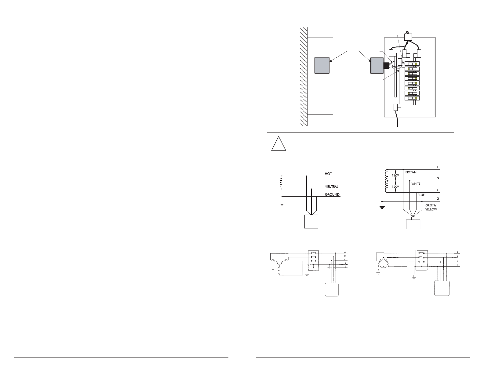
1. Disconnect all power supplying the electrical panel
2. Remove the panel screws and cover. Retain these parts for re-installation.
3. Either remove a knockout 0.5 inches (13mm) or install provided metal bracket
4. Remove lock washer from the SPDs threaded nipple. Carefully feed the wires through to
avoid cutting wire insulation. Slide lock washer over the wires to anchor the threaded
nipple. Rotate the SPD so that the function status LED indicators can be easily viewed.
Tighten the lock washer to secure the SPD.
5. Locate the neutral bar inside the electrical panel (except for 1455-21-D) and connect the
white or blue wire to the neutral bar and tighten to torque specified on inside of panel.
Keep conductor length as short as possible and avoid sharp bends in the wire.
6. Locate the ground bar inside the electrical panel. Connect the green/yellow wire to the
ground bar and tighten the terminal to the torque specified on the panel. Keep conductor
length as short as possible and avoid sharp bends. If neutral is bonded to ground, green
wire may be terminated to neutral.
7. Black or brown wires can be connected directly to the bus of the panel as long as the panels
short circuit current rating does not exceed 100kAIC. If you would like to be able to turn
the unit off, then you may consider connecting it to a breaker (# of positions determined by
the # of black or brown wires provided with the unit). Tighten terminals to torque specified
on inside of panel. Keep lead lengths as short as possible and avoid sharp bends.
8. Re-install panel cover.
Electrical Service Entry
Electrical Service Entry
Black (2 pls.)
Black (2 pls.)
Protector
Mounting Surface
Service
Service Panel Side
Panel Side
Protector
White
White
Green/Yellow
Green/Yellow
N
Ground
Ground
G
CAUTION: Do not assume the circuit is de-energized!
Remove power before performing any maintenance to the device.
1260-21
1265-21, 1265-21-G
Operation
1. Apply power to the panel. If the electrical and grounding wirings are done correctly, the
green function status LED will illuminate. If the LED is not on, remove the power and
review all of the previous installation procedures.
2. If after a known heavy lightning strike has occurred and the LED is off, reset the breaker if
it is tied to a breaker. If the function LED lights come back on then the protector is fine.
If the light is still out, or you can not reset the breaker, the protector must be replaced.
This unit contains no user serviceable parts.
SURGITRON®III INSTALLATION, OPERATION AND MAINTENANCE MANUAL SURGITRON®III INSTALLATION, OPERATION AND MAINTENANCE MANUAL
These instructions do not purport to cover all details or variations in equipment nor
to provide for every possible contingency to be met in connection with installation
operation or maintenance. Should further information be desired or should particular
problems arise which are not covered sufficiently for the purchaser’s purposes the matter
should be referred to Joslyn.
1455-21, 1455-21-A
1455-21-D
 Loading...