

Page 1
500ABARTH
OWNER HANDBOOK
Page 2
Dear Customer,
Thank you for choosing Abarth and congratulations on your choice of a Abarth.
We prepared this booklet to enable you to know each detail of your Abarth and use it correctly. Please, read it carefully
before driving your car. You will find information, tips and important warnings regarding the driving of your car to help you derive
the maximum from the technological features of your Abarth.
You are recommended to read carefully the warnings and indications, marked with the respective symbols:
personal safety;
the car’s wellbeing;
environmental protection.
The enclosed Warranty Booklet lists the services that Abarth offers to its Customers:
❒
the Warranty Certificate with terms and conditions for maintaining its validity
❒
the range of additional services available to Abarth Customers.
Best regards and happy motoring!
The special features of the new 500 Abarth make the car captivating through its unmistakeable appearance,
stylish yet traditional and, at the same time, practical in terms of performance and safety thanks to the new
elements that have been introduced. The miniskirts, the rear spoiler and the inclined connector to the underbody
improve the drag coefficient, the geometry and road holding at speed. The twin exhaust pipes are fitted at the
sides of the incline at the specular outlets of a single transversely mounted silencer. The front and rear
symmetrical air intakes are practical and the first ones allow the flow of air for cooling the two specular
intercoolers, while the second ones permit the outlet of the flow at the rear. The introduction of the TTC
system (Torque Transfer Control), which improves the transfer of engine torque to the wheels, makes the
vehicle safer and more pleasant to drive, especially when cornering. Comfort is improved thanks to the introduction
of the anti-roll bar which involves a reduction in shock absorber pressure thereby making the vehicle less rigid.
Every feature of the 500 Abarth passenger compartment, from the turbo analogue pressure gauge, the
steering wheel with three spokes and shaped grips, the aluminium pedal assembly, the gear lever with an
This Owner Handbook contains descriptions of the various new 500 Abarth trim levels therefore you should find
ergonimically designed grip and the seats with head restraints built-into the backrest,
is designed to give the car a sporty appearance.
the information that relates to the version you have purchased.
Page 3

YYOOUURR CCAAR
R
YOUR CAR
SAFETY
DEVICES
CAR
OF THE
CORRECT USE
WARNING
MESSAGES
LIGHTS AND
IN AN
EMERGENCY
CAR
MAINTENANCE
TECHNICAL
SPECIFICATIONS
DASHBOARD ...................................................................... 3
SYMBOLS ............................................................................... 4
THE FIAT CODE SYSTEM.................................................. 4
THE KEYS .............................................................................. 5
INSTRUMENT PANEL AND ONBOARD
INSTRUMENTS ..................................................................... 9
MULTIFUNCTIONAL DISPLAY AND
RECONFIGURABLE MULTIFUNCTIONAL DISPLAY 12
TRIP COMPUTER ................................................................ 21
SEATS ...................................................................................... 23
HEAD RESTRAINTS............................................................. 24
STEERING WHEEL .............................................................. 25
REARVIEW MIRRORS ......................................................... 26
CLIMATE COMFORT.......................................................... 27
HEATING AND VENTILATION ...................................... 28
MANUAL CLIMATE CONTROL SYSTEM .................... 29
AUTOMATIC CLIMATE CONTROL SYSTEM ............. 31
EXTERNAL LIGHTS............................................................. 34
WINDOW WASHING ....................................................... 35
CEILING LIGHTS ................................................................. 36
CONTROLS........................................................................... 37
INTERIOR FITTINGS........................................................... 39
SUNROOF.............................................................................. 41
DOORS .................................................................................. 43
POWER WINDOWS........................................................... 45
BOOT ...................................................................................... 46
BONNET................................................................................. 49
ROOF RACK/SKI RACK .................................................... 51
HEADLIGHTS ........................................................................ 51
ABS SYSTEM ......................................................................... 53
ESP SYSTEM ........................................................................... 54
EOBD SYSTEM ..................................................................... 57
“DUALDRIVE” ELECTRIC POWER
STEERING SYSTEM ............................................................. 58
SOUND SYSTEM .................................................................. 59
AT THE FILLING STATION ............................................. 61
PROTECTING THE ENVIRONMENT............................. 62
INDEX
2
Page 4
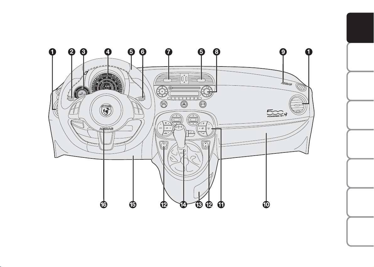
DASHBOARD
CD
The presence and position of the controls, instruments and gauges may vary depending on the trim level
fig. 1
F0S0001Ab
YOUR CAR
SAFETY
DEVICES
CAR
OF THE
CORRECT USE
WARNING
MESSAGES
LIGHTS AND
IN AN
EMERGENCY
CAR
MAINTENANCE
TECHNICAL
SPECIFICATIONS
1. Side vent – 2. Left stalk: external lights control – 3. Turbo pressure gauge – 4. Instrument panel and warning lights – 5. Portable
navigator preparation socket – 6. Right stalk: controls wiper, washer, trip computer – 7. Central air vents – 8. Oddment/Car radio
compartment – 9. Passenger air bag – 10. Oddment compartment/hidden document tray – 11. Heating/ventilation/climate control
– 12. Power windows control – 13. Oddment compartment – 14. Gear lever – 15. Knee bag – 16. Driver air bag.
INDEX
3
Page 5
YOUR CAR
SAFETY
DEVICES
CAR
OF THE
CORRECT USE
WARNING
MESSAGES
LIGHTS AND
IN AN
EMERGENCY
CAR
MAINTENANCE
SYMBOLS
Special coloured labels have been attached
near or actually on some of the components of your car. These labels bear symbols that remind you of the precautions
to be taken as regards that particular component.
The inner surface of the engine bonnet includes a label with the different symbols
used.
THE FIAT CODE SYSTEM
This is an electrical engine locking system
which increases protection from attempted theft of the car. It is automatically activated when the ignition key is extracted.
Each time the car is started turning the ignition key to MAR, the Fiat CODE system
control unit sends a recognition code to
the engine control unit to deactivate the inhibitor.
If, during ignition, the code is not correctly
recognized, the light
instrument panel.
In this case, turn the key to the STOP position and then to the MAR position; if it
is still locked, try again with the other keys
that come with the vehicle. If you have
still not managed to start the engine, contact an Abarth Dealership.
IMPORTANT Each key has its own code
which must be stored by the system ECU.
Contact the Abarth Dealership to have
new keys (up to eight) stored with the
code.
lights up on the
Y
Warning light Ycoming on when
driving
❒
If the warning light Yturns on, this
means that the system is running a selftest (such as following a voltage drop).
❒
If the issue persists, contact the Abarth
Dealership .
The electronic components
inside the key may be damaged if the key is submitted to
sharp knocks.
TECHNICAL
SPECIFICATIONS
INDEX
4
Page 6
THE KEYS
A
B
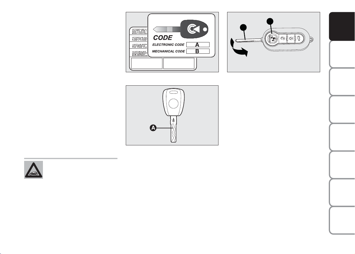
CODE CARD fig. 2
(for versions/markets, where provided)
The car is delivered with two copies of the
ignition key and with the CODE card
which bears the following:
A the electronic code.
B the mechanical key code to be given to
the Abarth Dealership when ordering
duplicate keys.
We recommend to have the electronic
code A always available.
IMPORTANT In order to ensure perfect
efficiency of the electronic devices contained inside the keys, they should never
be exposed to direct sunlight.
All the keys and the CODE
card must be handed over to
the new owner when selling
the car.
fig. 2
fig. 3
F0S0002Ab
F0S0003Ab
KEY WITHOUT REMOTE
CONTROL fig. 3
The metal insert A enables:
❒
the ignition switch;
❒
the door and tailgate (where provided);
❒
the fuel cap lock/release;
fig. 4
F0S0004Ab
KEY WITH REMOTE CONTROL
fig. 4
The metal insert A enables:
❒
the ignition switch;
❒
the doors;
❒
the fuel cap lock/release;
To open/close the metal insert, press button B.
YOUR CAR
SAFETY
DEVICES
CAR
OF THE
CORRECT USE
WARNING
MESSAGES
LIGHTS AND
IN AN
EMERGENCY
CAR
MAINTENANCE
TECHNICAL
SPECIFICATIONS
5
INDEX
Page 7

YOUR CAR
SAFETY
DEVICES
CAR
OF THE
CORRECT USE
WARNING
MESSAGES
LIGHTS AND
IN AN
EMERGENCY
CAR
MAINTENANCE
Door and
tailgate lock release
Short pressure on button
Ë
: door and tailgate lock release, timed turn on of ceiling
lights and double flashing of direction indicators (for versions/markets, where provided).
Door locks are automatically released in
case of intervention of the fuel cut-off system.
Lock of doors and
tailgate
Short pressure on button
Á
: remote lock
of doors and of tailgate with switch off of
ceiling lights and single flashing of direction
indicators (for versions/markets, where
provided).
If one or more doors are open, the lock
is not realized. This is signalled by a quick
flashing of the direction indicators (for versions/markets, where provided). Door
lock is realized in the event of open boot.
With speed over 20 km/h, the doors are
automatically locked, if this specific function was set (only with multi-function configurable display in the versions, for versions/markets, where provided).
Remote
tailgate opening
Keep pressed the button
R
for remote
opening of tailgate.
Tailgate opening is indicated by double
flashing of direction indicators.
TECHNICAL
SPECIFICATIONS
INDEX
6
Page 8
REQUEST FOR ADDITIONAL
REMOTE CONTROLS
The system may recognise up to 8 remote
controls. Should a new remote control be
necessary, contact a Abarth Dealership,
taking with you the CODE card, a personal identity document and the car’s
ownership documents.
YOUR CAR
SAFETY
DEVICES
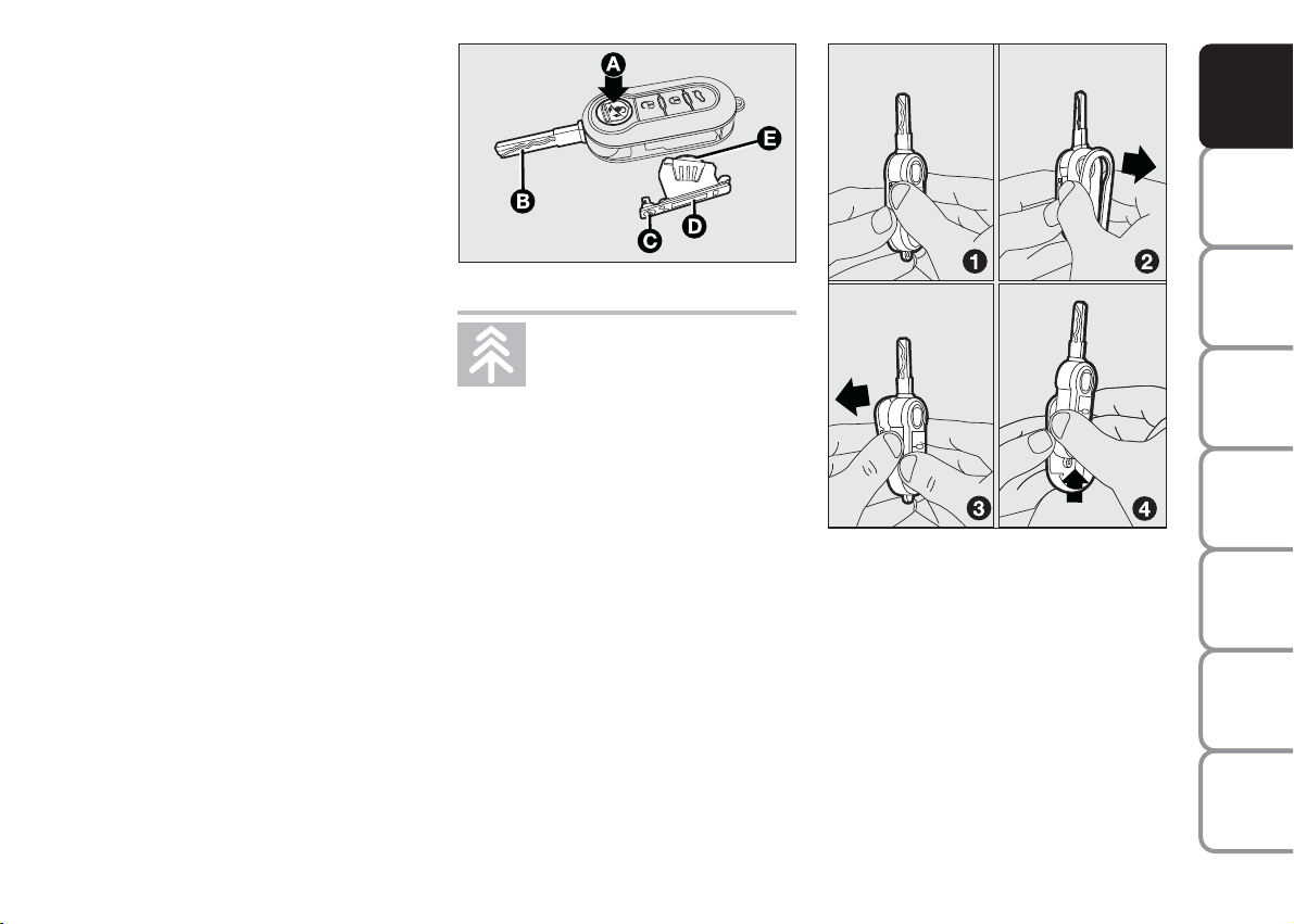
REPLACING THE BATTERY OF
THE KEY WITH REMOTE
CONTROL fig. 5
Battery replacement:
❒
press button A and open the metal insert B;
❒
rotate the screw C to :using a small
point screwdriver;
❒
take out the battery case D and replace
the battery E respecting its polarity;
❒
refit the battery case D inside the key
and lock it turning the screw C to
Á
fig. 5
Used batteries are harmful to
the environment. They should
be disposed of as specified by
law in the special containers
provided, or take them to the Abarth
Dealership, which will deal with their
disposal.
.
F0S0005Ab
fig. 6
F0S0006Ab
REPLACEMENT OF REMOTE
CONTROL COVER fig. 6
To replace the remote control cover, follow the procedure shown in figure.
CAR
OF THE
CORRECT USE
WARNING
LIGHTS AND
IN AN
EMERGENCY
CAR
MAINTENANCE
TECHNICAL
SPECIFICATIONS
INDEX
7
MESSAGES
Page 9
YOUR CAR
SAFETY
DEVICES
CAR
OF THE
CORRECT USE
WARNING
MESSAGES
LIGHTS AND
IN AN
EMERGENCY
CAR
MAINTENANCE
TECHNICAL
SPECIFICATIONS
fig. 7
F0S0007Ab
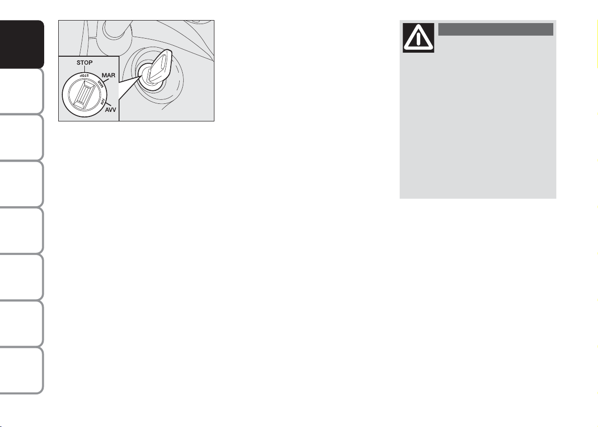
IGNITION
SWITCH fig. 7
The key can be turned to 3 different positions:
❒
STOP: engine off, key extractable,
steering locked. Some electrical devices
(e.g. car radio, central door locking system, etc.) are enabled
❒
MAR: driving position. All electrical devices are enabled
❒
AVV: engine start.
The ignition switch is fitted with a safety system that, if the engine does not start, forces
to return the ignition key to STOP before
repeating the starting operation.
STEERING COLUMN LOCK
Engaging
When the key is at STOP, remove the key
and turn the steering wheel until it locks.
Disengaging
Rock the steering wheel slightly as you
turn the ignition key to MAR.
WARNING
Never extract the key while
the vehicle is moving. The
steering wheel would be locked as
soon as the steering wheel is turned.
This also applies to when the car is
towed.
It is absolutely forbidden to carry out
whatever after-market operation involving steering system or steering column modifications (e.g.: installation
of anti-theft device) that could badly
affect performance and safety, cause
the lapse of warranty and also result
in non-compliance of the car with homologation requirements.
INDEX
8
Page 10
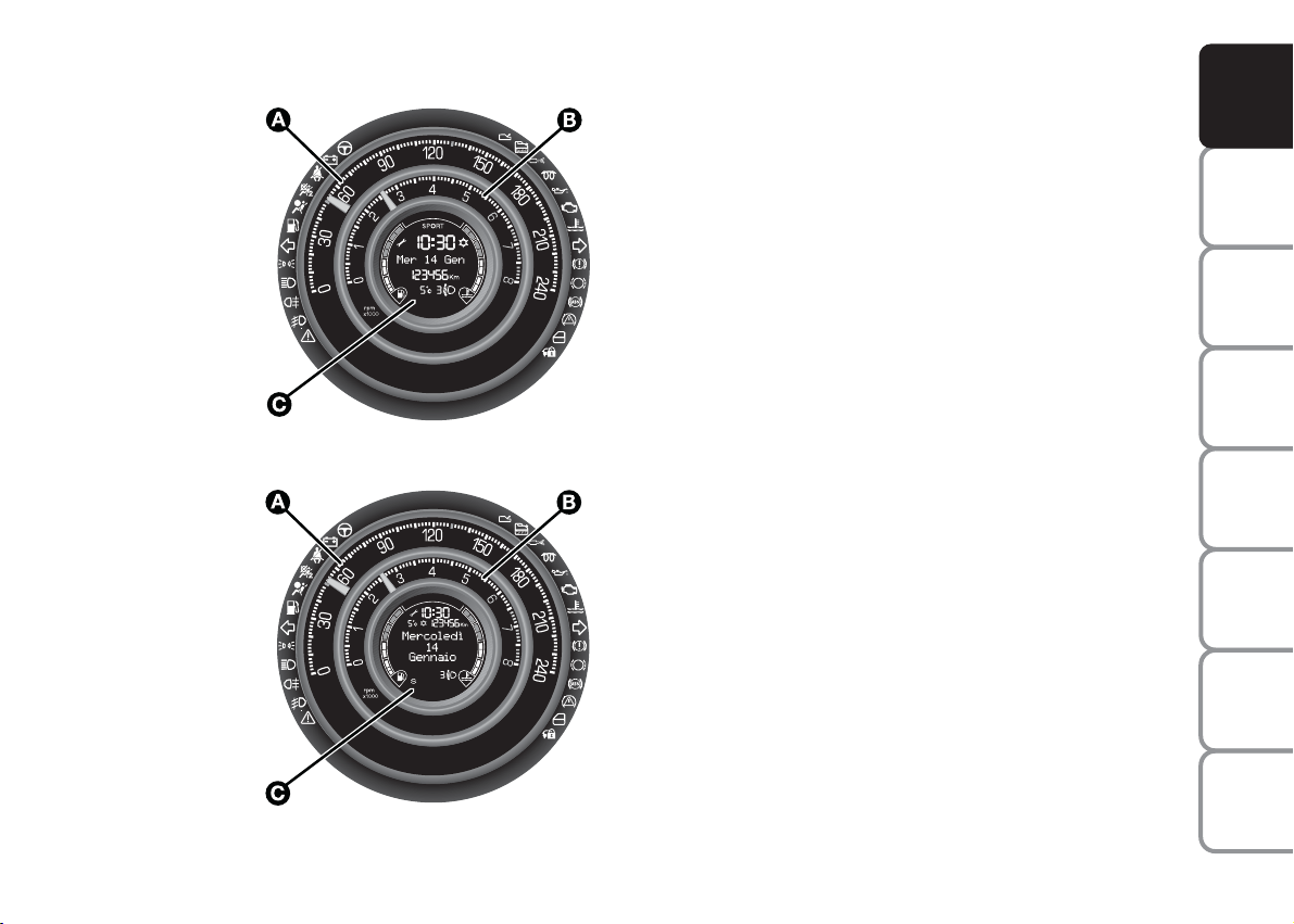
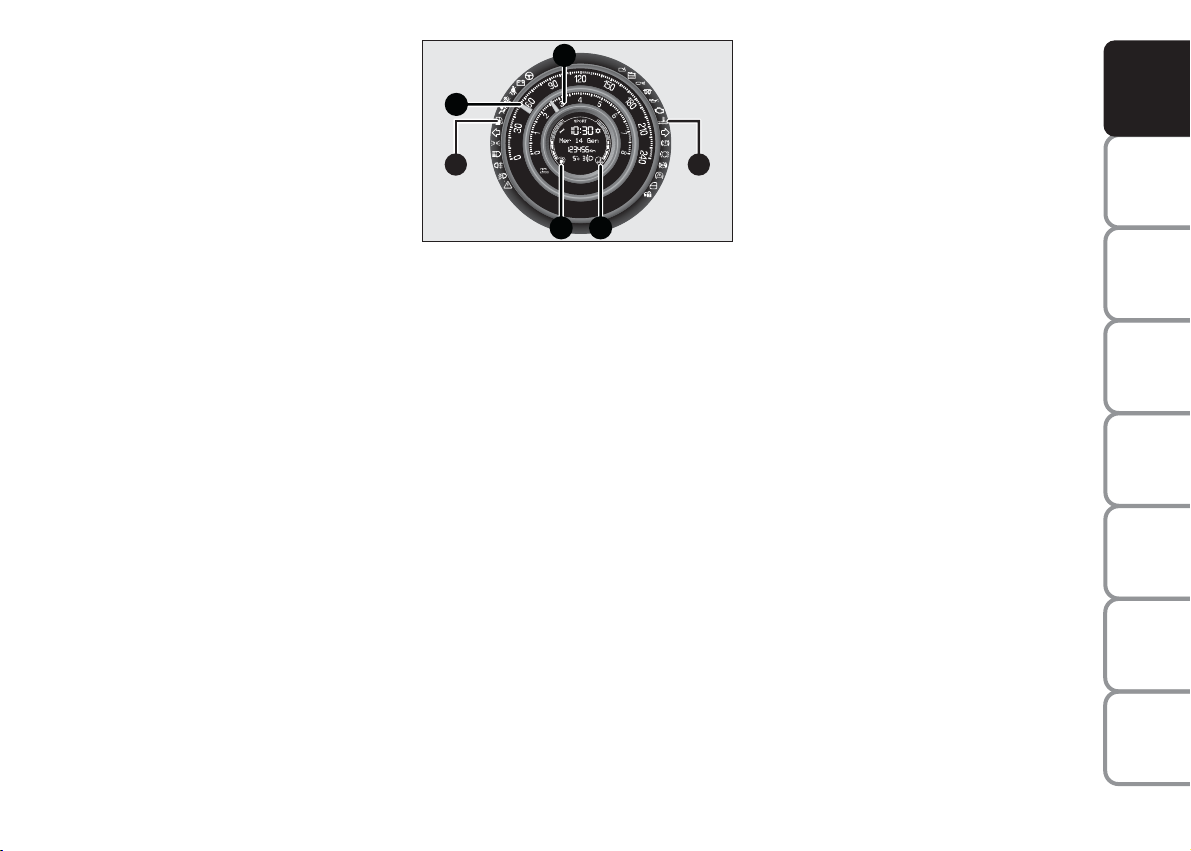
INSTRUMENT PANEL AND ONBOARD INSTRUMENTS
fig. 8
F0S0008Ab
Versions with multifunctional
display
A Speedometer (speed indicator)
B Rev counter
C Multifunctional display with digital fu-
el level indicator and digital indicator
of engine coolant temperature.
Versions with reconfigurable
multifunctional display
A Speedometer (speed indicator)
B Rev counter
C Configurable multifunctional display
with digital fuel level indicator and digital indicator of engine coolant temperature.
YOUR CAR
SAFETY
DEVICES
CAR
OF THE
CORRECT USE
WARNING
MESSAGES
LIGHTS AND
IN AN
EMERGENCY
CAR
MAINTENANCE
TECHNICAL
SPECIFICATIONS
fig. 9 -
Version with reconfigurable multifunctional display
INDEX
F0S0009Ab
9
Page 11
YOUR CAR
SAFETY
DEVICES
CAR
OF THE
CORRECT USE
WARNING
MESSAGES
LIGHTS AND
IN AN
EMERGENCY
CAR
MAINTENANCE
TECHNICAL
SPECIFICATIONS
INDEX
fig. 10
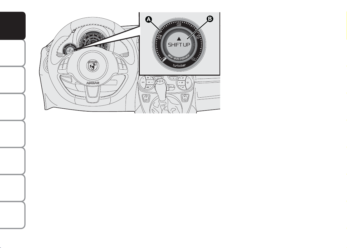
Analogue pressure gauge
for turbocharger pressure
The car is equipped with a pressure gauge
for measuring the turbocharger pressure
by means of the analogue indicator A.
CD
Note The turbocharger supercharging
pressure reading on the pressure gauge
should never exceed 1 – 1.2 bar even in
the case of sporty driving and maximum
performance.
A warning light B in the pressure gauge
signals the ideal time to change gear.
The gear change indication (arrow pointing upwards and words SHIFT UP) displays
a suggestion to change up to a higher gear.
F0S0010Ab
With the ignition in the MAR position, the
gear change indication lights up and goes
out together with the instrument panel
warning lights. Afterwards, the letter N
and the words SHIFT UP light up each
time there is a suggestion to change to a
higher gear.
Note The light signalled provided by the
instrument depends on the driving mode
selected.
With the SPORT mode on, the signalling
is only activated at the maximum speed
and therefore less frequently.
With the NORMAL mode activated, the
signalling is affected by driving economy
and therefore may be less frequent, at low
speeds as well.
10
Page 12
The main panel has a projection above it
B
A
C
D
E F
to prevent glare.
SPEEDOMETER
(SPEED INDICATOR)
fig. 11
The indicator A shows car speed
(speedometer).
REV. COUNTER fig. 11
The indicator B shows the engine revs.
fig. 11
F0S011Ab
DIGITAL FUEL LEVEL
INDICATOR fig. 11
The digital indicator C shows the amount
of fuel in the tank.
The reserve warning light E
K
turns on
to indicate that approximately 5 litres of
fuel are left in the tank.
Do not travel with the tank nearly empty:
lack of fuel supply could damage the catalyser.
ENGINE COOLANT
TEMPERATURE GAUGE fig. 11
The digital indicator D shows the temperature of the engine coolant and begins
to operate when the coolant temperature
exceeds approx. 50°C.
The first segment is always on to show the
correct operation of the system.
F
u
warning light may light up (together
with a message shown on the display) to
indicate that the coolant temperature is
too high; in this case, stop the engine and
contact the Abarth Dealership.
YOUR CAR
SAFETY
DEVICES
CAR
OF THE
CORRECT USE
WARNING
MESSAGES
LIGHTS AND
IN AN
EMERGENCY
CAR
MAINTENANCE
TECHNICAL
INDEX
11
SPECIFICATIONS
Page 13

YOUR CAR
I
E
F
G
L
H
D
B
C
A
C
B
G
A
H
I
F
D
E
SAFETY
DEVICES
MULTIFUNCTIONAL
DISPLAY AND
RECONFIGURABLE
MULTIFUNCTIONAL
DISPLAY
(for versions/markets, where provided)
WARNING
The car can be equipped with the multi-
CAR
functional/multifunctional reconfigurable
display that, according to the settings
OF THE
CORRECT USE
made, will show useful information necessary when driving.
“STANDARD” SCREEN
MESSAGES
LIGHTS AND
OF MULTIFUNCTIONAL
DISPLAY fig. 12
The standard screen shows the following
IN AN
information:
EMERGENCY
A Sport driving mode indication
B Scheduled servicing deadline
CAR
C Digital fuel level indicator
MAINTENANCE
D External temperature indicator (for
E Beam adjustment position (with low
TECHNICAL
SPECIFICATIONS
F Digital engine coolant temperature in-
INDEX
12
versions/markets, where provided)
beams on only)
dicator
fig. 12
F0S012Ab
G Odometer (distance travelled in kilo-
metres/miles)
H Date
I Possible presence of ice on road
L Time
“STANDARD” SCREEN
OF RECONFIGURABLE
MULTIFUNCTIONAL DISPLAY
fig. 13
The standard screen shows the following
information:
A Time
B Scheduled servicing deadline
C External temperature indicator (for
versions/markets, where provided)
D Possible presence of ice on road
E Date
fig. 13
F0S013Ab
F Digital fuel level indicator
G Beam adjustment position (with low
beams on only)
H Digital indicator of engine coolant tem-
perature
I Odometer (distance travelled in kilo-
metres/miles)
Page 14
fig. 14
M E N U
E S C
F0S014Ab
CONTROL BUTTONS fig. 15
+ To scroll the displayed menu and the
related options upwards or to increase the displayed value.
MENU ESC Press briefly to access the
menu and/or go to next
screen or to confirm the
required menu option.
Press longer to return to
the standard screen
– To scroll the displayed menu and the
related options downwards or to decrease the value displayed.
Note Buttons
+ and – activate different
functions according to the following situations:
– to scroll the menu options upwards and
downwards;
– to increase or decrease values during
settings.
Note When opening one of the front
doors, the display will turn on and show
for a few seconds the clock and the km or
mi covered (for versions/markets, where
provided).
SETUP MENU
The menu comprises a series of functions
arranged in a cycle which can be selected
through buttons
+ and – to access the dif-
ferent select operations and settings (setup) given in the following paragraphs. A submenu is provided for some items (Clock
and Unit setting). The setup menu can be
activated by pressing briefly button MENU
ESC. Single presses on buttons + or – will
scroll the setup menu options. Handling
modes differ with each other according to
the characteristic of the option selected.
The menu includes the following functions:
– MENU
– DIMMER
– SPEED BEEP
– TRIP B DATA/TRIP B ACTIVATION
– SET TIME
– SET DATE
– SEE RADIO
– AUTOCLOSE
– UNIT
– LANGUAGE
– BUZZER VOLUME
– BUTTON VOL.
– SEAT BELT BUZZER/SEAT BELT BEEPING
– SERVICE
– PASSENGER BAG
– DAYLIGHTS
– EXIT MENU
YOUR CAR
SAFETY
DEVICES
CAR
OF THE
CORRECT USE
WARNING
MESSAGES
LIGHTS AND
IN AN
EMERGENCY
CAR
MAINTENANCE
TECHNICAL
SPECIFICATIONS
INDEX
13
Page 15

YOUR CAR
SAFETY
DEVICES
CAR
OF THE
CORRECT USE
WARNING
MESSAGES
LIGHTS AND
IN AN
EMERGENCY
CAR
MAINTENANCE
Selecting an option of the main menu
without submenu:
– press briefly button MENU
ESC to se-
lect the main menu option to set;
– press buttons
+ or – (by single press-
es) to select the new setting;
– press briefly button MENU ESC to
store the new setting and go back to the
main menu option previously selected.
Selecting an option of the main menu with
submenu:
– briefly press button MENU
ESC to dis-
play the first submenu option;
– press buttons
+ or – (by single press-
es) to scroll all the submenu options;
– press briefly button MENU ESC to se-
lect the displayed submenu option and to
open the relevant setup menu;
– press buttons
+ or – (by single press-
es) to select the new setting for this submenu option;
– briefly press button MENU
ESC to
store the new setting and to go back to
the previously selected submenu option.
MENU FUNCTIONS
Lighting
(Car interior lighting adjustment)
This function is available with the dipped
headlamps on and at night to adjust the
brightness of the instrument panel, buttons, radio display and automatic climate
control display.
With the multifunction display, in the daytime and with the dipped headlamps on,
the instrument panel, radio display and automatic climate control display are on at
the maximum brightness setting.
With the reconfigurable multifunction display, in the daytime and with the dipped
headlamps on, the car interior lighting is
off. If the car goes into shade, for example, driving through a tunnel, the instrument panel, the buttons and the radio and
automatic climate control displays light up
at the second brightness setting.
TECHNICAL
SPECIFICATIONS
INDEX
14
Page 16

To adjust the brightness, proceed as follows:
– briefly press button MENU
ESC , the
previously set level will flash on the display;
– press button
+ or – to set the required
brightness level;
– briefly press button MENU
ESC to go
back to the menu screen or press the button for long to go back to the standard
screen without storing settings.
Speed beep (Speed limit)
With this function it is possible to set the
car speed limit (km/h or mph); when this
limit is exceeded the driver is immediately alerted (see section “Warning lights and
messages”).
To set the speed limit, proceed as follows:
– briefly press button MENU
ESC, the
display will show the message (Speed
Buzz);
– press button + or – to select speed limit activation (On) or deactivation (Off);
– when the function is activated (On)
pressing buttons
+ or – select the speed
limit and press MENU ESC to confirm
selection.
Note Selection is possible between 30
and 200 km/h, or 20 and 125 mph depending on the selected unit, see paragraph “Unit of measure”. The setting will
increase/decrease by five units each time
+/– is pressed. Hold button +/–
button
pressed to increase/decrease the setting
rapidly. Complete the setting by briefly
pressing the button when you approach
the required setting.
– briefly press button MENU
ESC to go
back to the menu screen or press the button for long to go back to the standard
screen without storing settings.
To cancel the setting, proceed as follows:
– briefly press button MENU
ESC: (On)
will flash on the display;
– press button
–: (Off) will flash on the dis-
play;
– briefly press button MENU
ESC to go
back to the menu screen or press the button for long to go back to the standard
screen without storing settings.
YOUR CAR
SAFETY
DEVICES
CAR
OF THE
CORRECT USE
WARNING
MESSAGES
LIGHTS AND
IN AN
EMERGENCY
CAR
MAINTENANCE
TECHNICAL
INDEX
15
SPECIFICATIONS
Page 17

YOUR CAR
SAFETY
DEVICES
CAR
OF THE
CORRECT USE
WARNING
MESSAGES
LIGHTS AND
IN AN
EMERGENCY
CAR
MAINTENANCE
Trip B data (Trip B on)
Through this option it is possible to activate (On) or deactivate (Off) the Trip B
(partial trip) display.
For further information see “Trip computer”.
For activation / deactivation, proceed as
follows:
– briefly press button MENU
ESC: (On)
or (Off) will flash on the display (according to previous setting);
– press button
+ or – for setting;
– briefly press button MENU ESC to go
back to the menu screen or press the button for long to go back to the standard
screen without storing settings.
Set time (Clock)
This function enables to set the clock
through two sub-menus: “Time” and
“Mode”.
Proceed as follows:
– briefly press button MENU
ESC, the
display will show the two sub-menus
“Time” and “Mode”;
– press button
+ or – to navigate the two
sub-menus;
– select the required option and then
press button MENU
ESC;
– when accessing the “Time” submenu:
briefly press button MENU ESC, “hours”
will flash on the display;
– press button
+ or – for setting;
– briefly press button MENU ESC, “minutes” will flash on the display;
– press button
+ or – for setting.
NoteThe setting will increase or decrease
by one unit each time
+ or – is pressed.
Hold the button pressed to increase/decrease the setting rapidly. Complete the
setting by briefly pressing the button when
you approach the required setting.
– when accessing the “Format” submenu:
briefly press button MENU
ESC: the pre-
viously set display format will flash on the
display;
– press button + or – to select “24h” or
“12h”.
When you have made the required settings, briefly press button MENU
ESC to
go back to the menu screen or press the
button for long to go back to the standard
screen without storing settings.
– hold MENU
ESC pressed to go back to
the standard screen or main menu according to the points of the menu where
you are at.
TECHNICAL
SPECIFICATIONS
INDEX
16
Page 18

Set date (Set Date)
This function enables to update the date
(day - month - year).
To correct the date proceed as follows:
– briefly press button MENU
ESC: “year”
will flash on the display;
– press button
– briefly press button MENU
+ or – for setting;
ESC:
“month” will flash on the display;
– press button
+ or – for setting;
– briefly press button MENU ESC: “day”
will flash on the display;
– press button + or – for setting.
NoteThe setting will increase or decrease
by one unit each time
+ or – is pressed.
Hold the button pressed to increase/decrease the setting rapidly. Complete the
setting by briefly pressing the button when
you approach the required setting.
– briefly press button MENU
ESC to go
back to the menu screen or press the button for long to go back to the standard
screen without storing settings.
See radio
(Repeat audio information)
With this function the display shows information relevant to the sound system.
– Radio: tuned radio station frequency or
RDS message, automatic tuning activation
or AutoSTore;
– CD audio, CD MP3: track number;
To activate (On) or to deactivate (Off)
sound system info displaying proceed as
follows:
– briefly press button MENU
ESC: (On)
or (Off) will flash on the display (according to previous setting);
– press button
+ or – for setting;
– briefly press button MENU ESC to go
back to the menu screen or press the button for long to go back to the standard
screen without storing settings.
Autoclose (Automatic door lock
operation with car running)
(for versions/markets, where provided)
When activated (On), this function locks
automatically the doors when the car
speed exceeds 20 km/h.
Proceed as follows to switch this function
on or off:
– briefly press button MENU
ESC to dis-
play the three sub-menus;
– briefly press button MENU
ESC: (On)
or (Off) will flash on the display (according to previous setting);
– press button
– briefly press button MENU
+ or – for setting;
ESC to go
back to the menu screen or press the button for long to go back to the standard
screen without storing settings;
– hold MENU
ESC pressed to go back to
the standard screen or main menu according to the points of the menu where
you are at.
YOUR CAR
SAFETY
DEVICES
CAR
OF THE
CORRECT USE
WARNING
MESSAGES
LIGHTS AND
IN AN
EMERGENCY
CAR
MAINTENANCE
TECHNICAL
INDEX
17
SPECIFICATIONS
Page 19

YOUR CAR
SAFETY
DEVICES
CAR
OF THE
CORRECT USE
WARNING
MESSAGES
LIGHTS AND
IN AN
EMERGENCY
CAR
MAINTENANCE
Units (Set units)
This function may be used to set the measurement unit in three submenus: “Distances”, “Consumption” and “Temperature”.
To set the required unit proceed as follows:
– briefly press button MENU
ESC to dis-
play the three sub-menus;
– press button + or – to navigate the
three sub-menus;
– select the required sub-menu and then
press briefly button MENU
ESC;
– when accessing the “Distance” submenu:
briefly press MENU
ESC: either “km” or
“mi” will appear on the display (according to the previous setting);
– press button + or – for setting;
– when accessing the “Consumption” submenu: briefly press MENU ESC: either
“km/l ”, “l/100km” or “mpg” will appear
on the display (according to the previous
setting);
If the distance unit set is “km” the fuel consumption unit will be displayed in km/l or
l/100km.
If the distance unit set is “mi” the fuel consumption unit will be displayed in “mpg”.
– press button
+ or – for setting;
– when accessing the “Temperature” submenu: briefly press MENU
ESC: either
“°C” or “°F” will appear on the display according to the previous setting;
– press button + or – for setting;
When you have made the required settings, briefly press button MENU
ESC to
go back to the menu screen or press the
button for long to go back to the standard
screen without storing settings.
– hold MENU
ESC pressed to go back to
the standard screen or main menu according to the points of the menu where
you are at.
Language (Selecting the language)
The messages can be displayed in the following languages: Italian, English, German,
Portuguese, Spanish, French, Dutch, Polish.
To set the required language proceed as
follows:
– briefly press button MENU
ESC: the
previously set “language” will flash on the
display;
– press button + or – for setting;
– briefly press button MENU
ESC to go
back to the menu screen or press the button for long to go back to the standard
screen without storing settings.
TECHNICAL
SPECIFICATIONS
INDEX
18
Page 20

Buzzer volume
(Adjusting the failure/warning
buzzer volume)
With this function the volume of the
buzzer accompanying any failure/warning
indication can be adjusted according to 8
levels.
To adjust the volume proceed as follows:
– briefly press button : MENU
ESC; the
previously set volume “level” will flash on
the display;
– press button
– briefly press button MENU
+ or – for setting;
ESC to go
back to the menu screen or press the button for long to go back to the standard
screen without storing settings.
Button volume
(Button volume adjustment)
This function may be used to adjust the
volume of the beep accompanying the activation of buttons MENU
ESC, + and
– can be adjusted according to 8 levels.
To adjust the volume proceed as follows:
– briefly press button : MENU
previously set volume “level” will flash on
the display;
– press button
+ or – for setting;
– briefly press button MENU
back to the menu screen or press the button for long to go back to the standard
screen without storing settings.
ESC; the
ESC to go
Belt buzzer (Buzzer activation for
S.B.R. indication)
This function can be only displayed after
Abarth Dealership has deactivated the
S.B.R. system (see paragraph “S.B.R. system” in section “Safety devices”).
Service
(Scheduled servicing)
Through this function it is possible to display information connected to proper car
servicing.
Proceed as follows:
– briefly press button MENU
ESC: ser-
vice in km or mi, according to previous
setting, will be displayed (see paragraph
“Units”);
– briefly press button MENU
ESC to go
back to the menu screen or press the button for long to go back to the standard
screen.
YOUR CAR
SAFETY
DEVICES
CAR
OF THE
CORRECT USE
WARNING
MESSAGES
LIGHTS AND
IN AN
EMERGENCY
CAR
MAINTENANCE
TECHNICAL
INDEX
19
SPECIFICATIONS
Page 21

YOUR CAR
SAFETY
DEVICES
CAR
OF THE
CORRECT USE
WARNING
MESSAGES
LIGHTS AND
IN AN
EMERGENCY
CAR
MAINTENANCE
TECHNICAL
SPECIFICATIONS
Note The “Service Schedule” requires the
car to be serviced every 30,000 km (or
18,000 mi); this indication will appear automatically with the key on MAR when
there are 2,000 km left (or equivalent distance in miles) and will be presented automatically every 200 km (or equivalent
distance in miles). The indications will appear more frequently where there are 200
km left. The indication will appear in kilometres or miles according to the settings.
When the next scheduled service operation is approaching, the message “Service”
will appear on the display followed by the
number of kilometres or miles left when
the key is turned to MAR. Go to the
Abarth Dealership where the “Scheduled
Service” operations will be performed and
the message will be reset.
Passenger bag
Front passenger’s airbag and
side bag activation/deactivation
(for versions/markets, where provided)
This function enables to activate/deactivate the front passenger’s air bag.
Proceed as follows:
– press button MENU
ESC and, after dis-
playing the message (Bag pass: Off) (to disable) or (Bag pass: On) (to enable) pressing buttons + and –, press again button
MENU
ESC;
- the confirmation request message will be
displayed;
- press buttons
+ or – to select (Yes)
(confirming activation/deactivation) or
(No) (to abort);
- briefly press MENU ESC to confirm setting and go back to the menu screen or
press the button for long to go back to the
standard screen without storing settings.
Daylights (D.R.L.)
This function enables to activate/deactivate the daylight light.
Proceed as follows to switch this function
on or off:
– briefly press button MENU
ESC to dis-
play the three sub-menus;
– briefly press button MENU
ESC: (On)
or (Off) will flash on the display (according to previous setting);
– press button + or – for setting;
– briefly press button MENU
ESC to go
back to the menu screen or press the button for long to go back to the standard
screen without storing settings;
– hold MENU ESC pressed to go back to
the standard screen or main menu according to the points of the menu where you are
at.
Exit Menu
This is the last function that closes the circular setting cycle listed in the initial menu
screen.
Briefly press button MENU
ESC to go
back to the standard screen without storing settings.
Press button
– to return to the first menu
option (Speed Beep).
INDEX
20
Page 22

TRIP COMPUTER
General features
The “Trip computer” is used to display information on car operation when the key
is turned to MAR. This function allows to
define two separate trips called “Trip A”
and “Trip B” for monitoring the car’s
“complete mission” in a reciprocally independent manner.
Both functions are resettable (reset - start
of new mission).
“Trip A” shall be used to display the figures relating to:
– Range
– Trip distance
– Average consumption
– Instant consumption
– Average speed
– Travel time (driving time).
“Trip B” shall be used to display the figures relating to:
– Trip distance B
– Average consumption B
– Average speed B
– Travel time B (driving time).
Note “Trip B” functions may be excluded (see “Trip B on”). “Range” and “Instantaneous consumption” cannot be reset.
Values displayed
Range
The distance that can be travelled with the
fuel in the tank is displayed, with the theory that driving will continue in the same
conditions. The display will show the reading “----” when the following events take
place:
– value lower than 50 km (or 30 mi)
– the car is parked with the engine running for a long time.
IMPORTANT The range depends on several factors: driving style (see “Driving
style” in “Starting and driving”), type of
route (motorway, urban cycle, mountain
roads, etc…), conditions of use of the car
(load, tyre pressure, etc…). Trip planning
must take into account the above notes.
Distance travelled
This value shows the distance covered
from the start of the new mission.
Average consumption
This value shows the approximate average consumption from the start of the
new mission.
Instant consumption
This indicates the fuel consumption. The value is constantly updated. The message
“----” will appear on the display if the car is
parked with the engine running.
YOUR CAR
SAFETY
DEVICES
CAR
OF THE
CORRECT USE
WARNING
MESSAGES
LIGHTS AND
IN AN
EMERGENCY
CAR
MAINTENANCE
TECHNICAL
INDEX
21
SPECIFICATIONS
Page 23
Average speed
This value shows the car average speed as
a function of the overall time elapsed since
YOUR CAR
the start of the new mission.
Start of trip procedure
With ignition key on MAR, press and hold
button TRIP pressed for over 2 seconds
to reset.
SAFETY
DEVICES
CAR
OF THE
CORRECT USE
WARNING
MESSAGES
LIGHTS AND
IN AN
EMERGENCY
CAR
MAINTENANCE
TECHNICAL
SPECIFICATIONS
INDEX
Travel time
This value shows the time elapsed since
the start of the new mission.
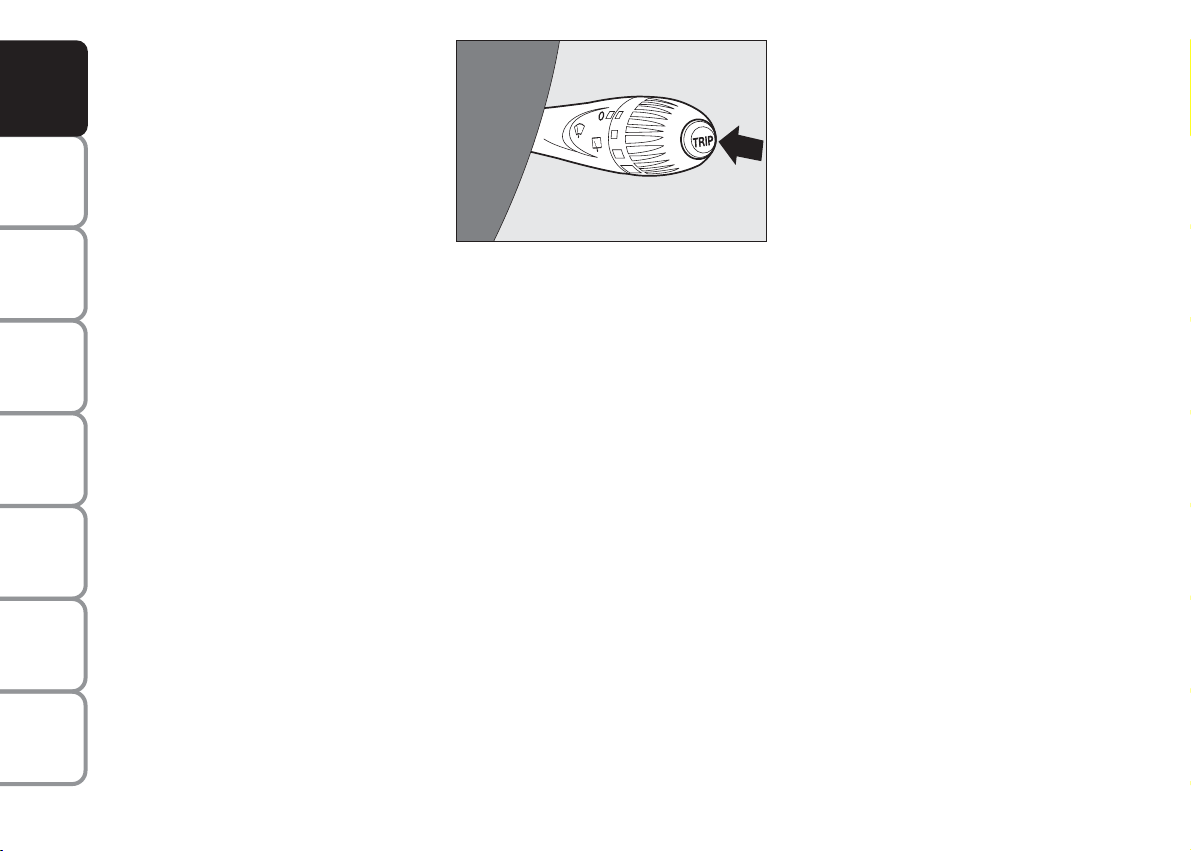
TRIP button fig. 15
Button TRIP, set on the right steering
column stalk, shall be used (with ignition
key on MAR) to display and to reset the
previously described values to start a new
mission:
– short push to display the different values;
– long push to reset and then start a new
mission.
fig. 15
F0S015Ab
New mission
Reset can be:
– “manual” resetting by the user, by pressing the relevant button;
– “automatic” resetting, when the “Trip distance” reaches 9999.9 km or when the
“Travel time” reaches 99.59 (99 hours and
59 minutes);
– after disconnecting/reconnecting the
battery.
IMPORTANT The reset operation in the
presence of the screens concerning the
“Trip A” makes it possible to reset only
the information associated with this function.
IMPORTANT The reset operation in the
presence of the screens concerning the
“Trip B” makes it possible to reset only
the information associated with this function.
Exit Trip
The TRIP function is over when all the
values have been displayed or holding the
button MENU
ESC pressed for longer
than 1 second.
22
Page 24
SEATS
2
3
4
6
5
1
D D
FRONT SEATS
WARNING
All adjustments must be
made with the car station-
ary.
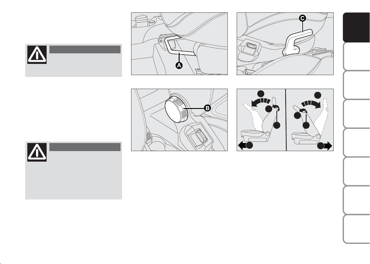
Fore/aft adjustment fig. 16
Lift lever A and push the seat forwards and
backwards: your arms should rest on the
steering wheel rim while you are driving.
WARNING
After releasing the lever, al-
ways check that the seat is
locked on the guides by trying to
move it backwards and forth. If it is
not locked, the seat may move unexpectedly and make you lose control
of the car.
Back rest angle adjustment fig. 17
Turn knob B.
fig. 16
fig. 17
F0S0013m
F0S0014m
Seat height adjustment
fig. 18
Operating lever C it is possible to lift or
lower the rear area of the cushion to
achieve the most comfortable driving position.
fig. 18
fig. 19
F0S0015m
F0S0154m
Backrest tilting fig. 19
To tilt the backrest, operate the lever D
(movement a) and push the backrest forward until it locks (movement b); release
the lever D and, pushing the backrest,
slide the seat forward (movement c).
YOUR CAR
SAFETY
DEVICES
CAR
OF THE
CORRECT USE
WARNING
MESSAGES
LIGHTS AND
IN AN
EMERGENCY
CAR
MAINTENANCE
TECHNICAL
SPECIFICATIONS
INDEX
23
Page 25
YOUR CAR
SAFETY
DEVICES
CAR
OF THE
CORRECT USE
WARNING
MESSAGES
LIGHTS AND
IN AN
EMERGENCY
CAR
MAINTENANCE
TECHNICAL
SPECIFICATIONS
Driver side and passenger side where
position memory is provided
To return the seat to its initial position,
slide the seat backward pushing the backrest until the seat locks (movement d)
operate the lever D (movement e) and
lift the backrest (movement f) until you
hear it snapping in position.
WARNING Using the lever D before
locking the seat in the initial position causes the loss of the seat initial position. In
that case, it is necessary to adjust the seat
position by means of the longitudinal adjustment fig. 16.
Passenger side where position
memory is not provided
To return the seat to its initial position,
slide the seat backward pushing the backrest to the desired position (movement
d); operate the lever D (movement e)
and lift the backrest (movement f) until
you hear it snapping in position.
WARNING
All adjustments must be
made with the car stationary.
fig. 20
F0S020Ab
The type of reattachment manoeuvre has
been chosen to guarantee the safety of the
occupant. In effect, if the mechanism detects an obstacle (e.g. a bag) and cannot
restore the seat to its original position, it
allows the reattachment of the actual seat,
positioning the backrest only, ensuring
that the guides are attached.
REAR SEATS fig. 20
Backrest release
❒
For versions with joint seat, lift handles A
and B and guide the backrest onto the
cushion.
❒
For versions with separate seats, lift handle Aor B to release respectively the left
or right part of the backrest and guide the
backrest onto the cushion.
HEAD RESTRAINTS
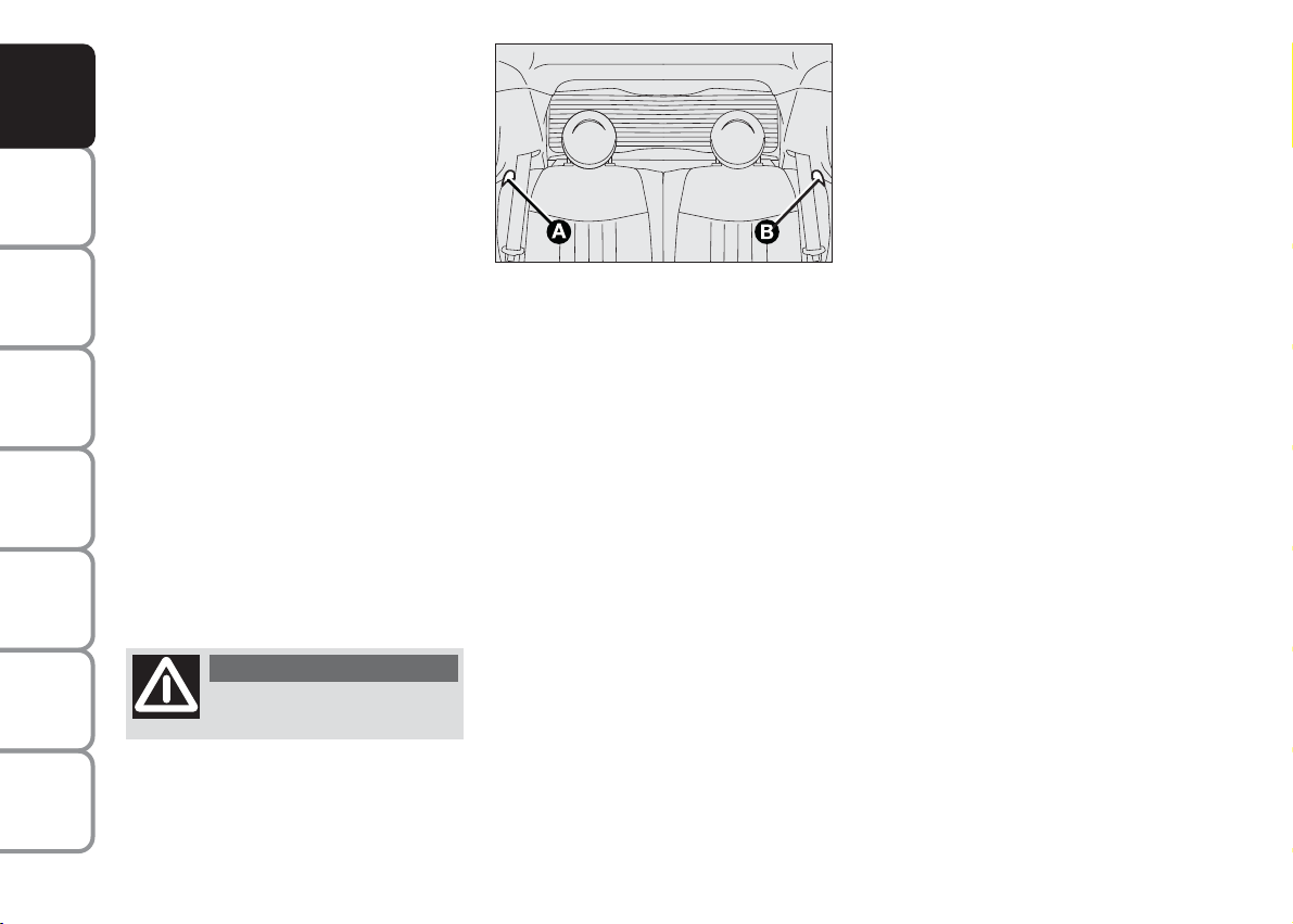
REAR fig. 21
(for versions/markets, where provided)
To lift out rear head restraints: press at
the same time buttons B e C set on both
sides and take them out. Rear head restraints must be lifted out with backrest
released and tilted toward the passenger
compartment or with the tailgate open.
To bring the head restraint in correct position, lift it until you hear it click.
To lower the head restraint, press button
B. The specific shape of the head restraint
interferes with the correct rest of the
back of the rear passenger on the backrest; the shape is useful to force the passenger to lift the headrest for its correct
use.
IMPORTANT Rear seat passengers shall
always set the head restraints in “fully
drawn out” position.
INDEX
24
Page 26
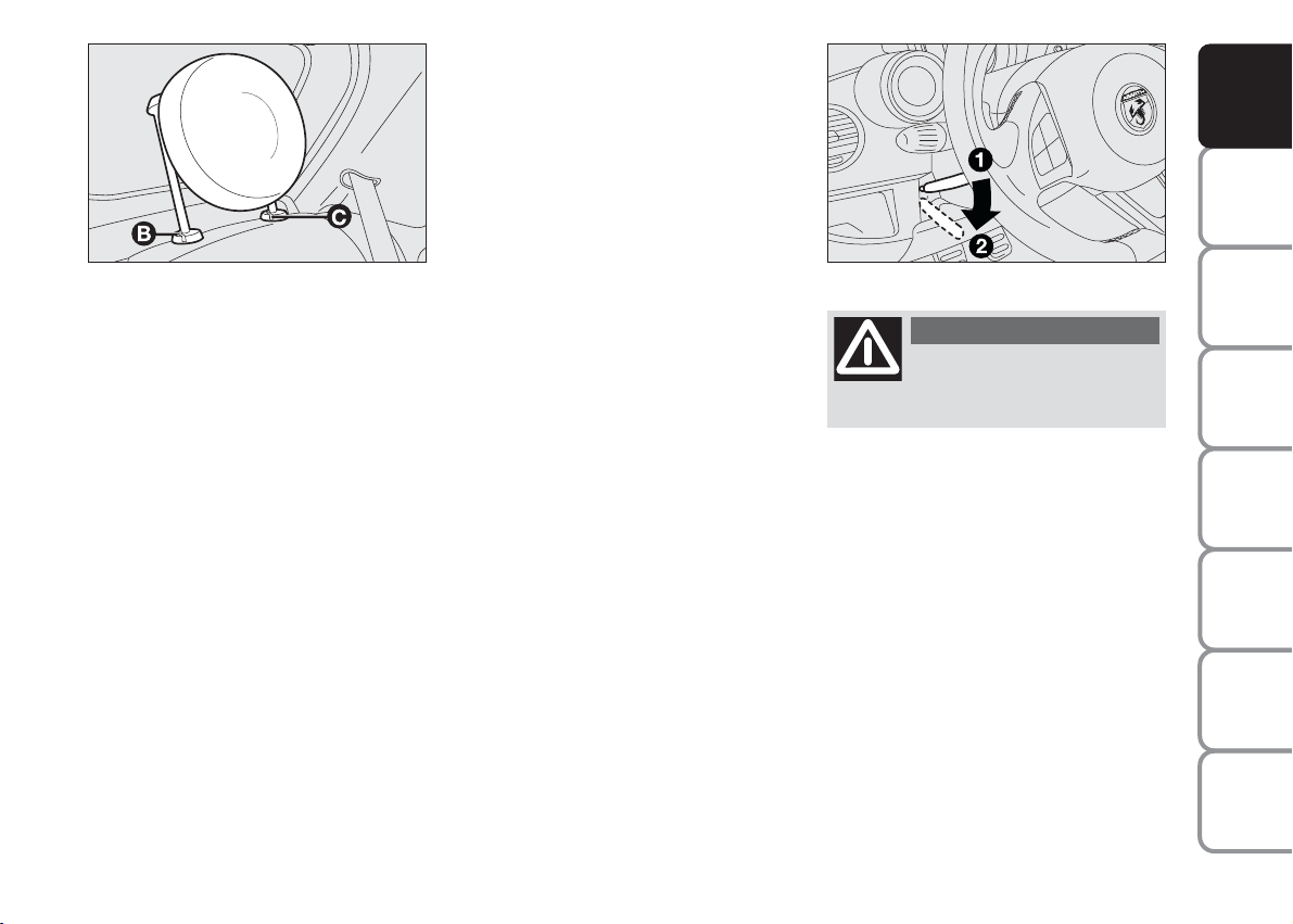
STEERING WHEEL
fig. 21
F0S021Ab
It can be adjusted vertically (for versions/
markets, where provided).
For adjustment. bring the lever A-fig. 22
downward to position 2 then position the
wheel and lock it bringing lever A to position 1.
fig. 22
F0S022Ab
WARNING
Perform these operations
only when the car is station-
ary and the engine is not running.
YOUR CAR
SAFETY
DEVICES
CAR
OF THE
CORRECT USE
WARNING
MESSAGES
LIGHTS AND
IN AN
EMERGENCY
CAR
MAINTENANCE
TECHNICAL
SPECIFICATIONS
25
INDEX
Page 27

YOUR CAR
SAFETY
DEVICES
CAR
OF THE
CORRECT USE
WARNING
MESSAGES
LIGHTS AND
IN AN
EMERGENCY
CAR
MAINTENANCE
REARVIEW MIRRORS
DRIVING MIRROR fig. 23
The mirror is fitted with a safety device
that causes its release in the event of a violent crash.
It can be moved using the lever A to two
different positions: normal or antiglare.
ELECTROCHROMIC DRIVING
MIRROR
(for versions/markets, where provided)
Some versions provide an electrochromic
mirror with automatic antiglare function.
An ON/OFF button in the lower area of
the mirror enables/disables the electrochromic function. When the function
is active, a led on the mirror is active. Engaging reverse gear, the mirror is automatically set for daylight use.
fig. 23
F0S023Ab
DOOR MIRRORS
with electrical adjustment fig. 24
Proceed as follows:
❒
select the mirror with selector B;
❒
adjust the mirror using the joystick A
in the four directions.
Folding back door mirrors fig. 25
When required (for example when the
mirror causes difficulty in narrow spaces)
it is possible to fold the mirror moving it
from position 1 open, to position 2 closed.
fig. 24
fig. 25
WARNING
The door mirrors, being
curved, slightly alter the per-
ception of distance.
F0S024Ab
F0S025Ab
TECHNICAL
SPECIFICATIONS
INDEX
26
WARNING
When driving, the mirrors
shall always be in position 1.
Page 28
CLIMATE COMFORT
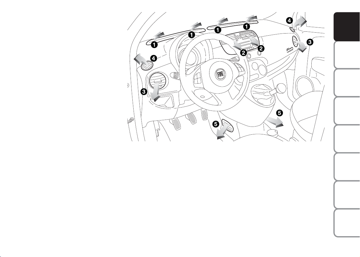
VENTS fig. 26
1. Vents for demisting/defrosting the
windscreen
2. Orientable, adjustable central vents
3. Orientable, adjustable side vents
4. Fixed vents for side windows.
5. Lower vents
fig. 26
F0S026Ab
YOUR CAR
SAFETY
DEVICES
CAR
OF THE
CORRECT USE
WARNING
MESSAGES
LIGHTS AND
IN AN
EMERGENCY
CAR
MAINTENANCE
TECHNICAL
SPECIFICATIONS
27
INDEX
Page 29
YOUR CAR
TTC
A
E
B C D
SAFETY
DEVICES
CAR
OF THE
CORRECT USE
WARNING
MESSAGES
LIGHTS AND
IN AN
EMERGENCY
CAR
MAINTENANCE
TECHNICAL
SPECIFICATIONS
INDEX
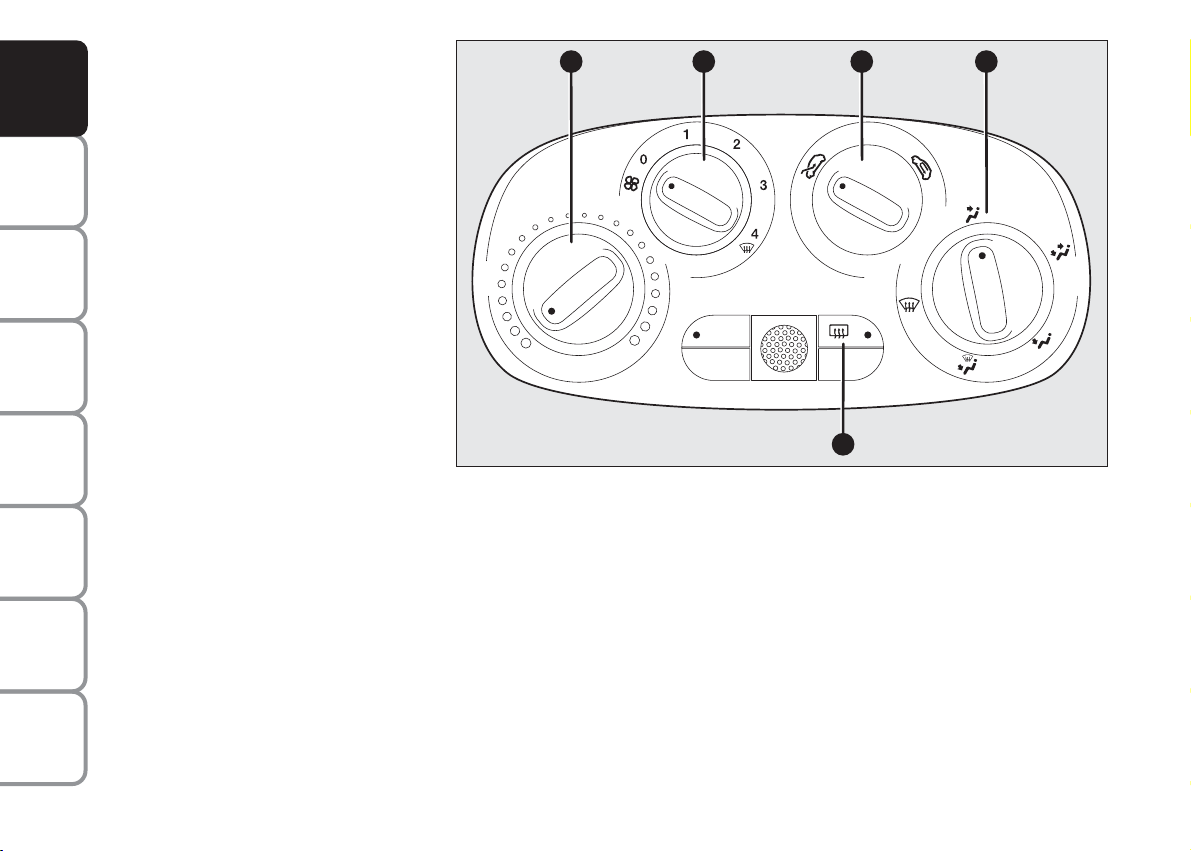
HEATING
AND VENTILATION
CONTROLS fig. 27
A Air temperature knob (red-hot / blue-
cold)
B Fan speed knob
NOTE Turn the knob to 0 to stop the
flow of air coming out of the vents.
C Air recycle knob
…
– internal air recycle
Ú
– air intake from outside
IMPORTANT Turn the recirculation function on to prevent the intake of air into
the passenger compartment; this is particularly advisable when stopped in a tunnel or in traffic to prevent the intake of
outside polluted air. Do not use the function for a long time, particularly if there
are many passengers on board, to prevent
the windows from misting up.
D Air distribution knob
μ
toward the body and the side windows
∑
toward the body, the side windows and the feet
∂
toward the feet only
fig. 27
∏
toward the feet and the windshield
-
toward the windscreen only.
E Button to activate/deactivate the heat-
ed rear window.
When the function is active, a led on
the button is on.
In order to maintain battery efficiency, the function is automatically deactivated after about 20 minutes.
Fast front window
demisting/defrosting
Proceed as follows:
❒
rotate knob A to red section;
❒
rotate knob C to Ú;
❒
rotate knob D to -;
❒
rotate knob B to 4-(max. fan speed).
F0S027Ab
28
Page 30
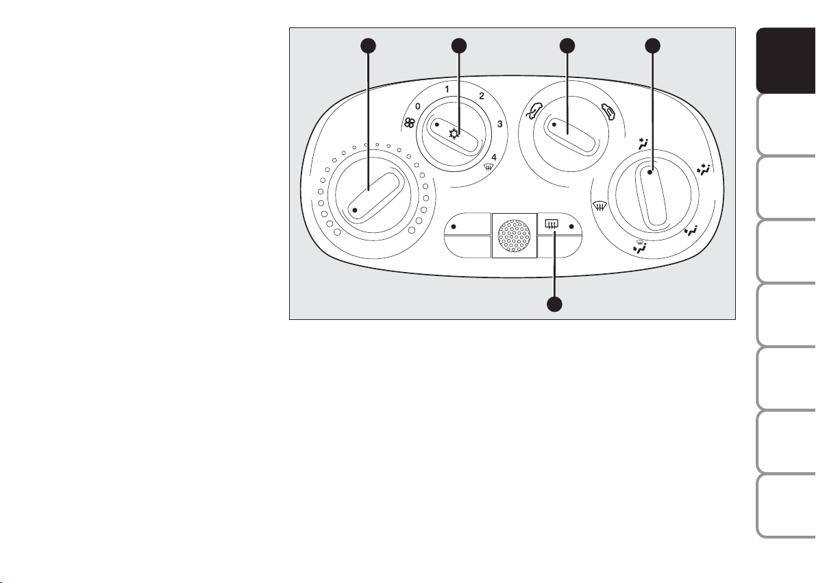
MANUAL CLIMATE
TTC
A
E
B C D
CONTROL SYSTEM
(for versions/markets, where provided)
CONTROLS fig. 28
A Air temperature knob (red-hot / blue-
cold)
B Fan speed knob and climate control
system activation/deactivation. Press
the knob to activate the climate control system; the led on the knob is active. This enables passenger compartment quick cooling.
NOTE Turn the knob to 0 to stop the
flow of air coming out of the vents.
C Air recycle knob
…
– internal air recycle
Ú
– air intake from outside
fig. 28
F0S028Ab
YOUR CAR
SAFETY
DEVICES
CAR
OF THE
CORRECT USE
WARNING
MESSAGES
LIGHTS AND
IN AN
EMERGENCY
IMPORTANT Turn the recirculation function on to prevent the intake of air into
the passenger compartment; this is particularly advisable when stopped in a tunnel or in traffic to prevent the intake of
outside polluted air. Do not use the function for a long time, particularly if there
are many passengers on board, to prevent
the windows from misting up.
D Air distribution knob
μ
toward the body and the side windows
∑
toward the body, the side windows and the feet
∂
toward the feet only
∏
toward the feet and the windshield
-
toward the windscreen only.
E Button to activate/deactivate the heat-
ed rear window.
When the function is active, a led on
the button is on.
In order to maintain battery efficiency, the function is automatically deactivated after about 20 minutes.
CAR
TECHNICAL
INDEX
29
MAINTENANCE
SPECIFICATIONS
Page 31

YOUR CAR
SAFETY
DEVICES
CAR
OF THE
CORRECT USE
WARNING
MESSAGES
LIGHTS AND
IN AN
EMERGENCY
CAR
MAINTENANCE
Fast front window and front side
windows demisting/defrosting
(MAX-DEF)
Proceed as follows:
❒
rotate knob A to red section;
❒
rotate knob C to Ú;
❒
rotate knob D to -;
❒
rotate knob B to 4-(max. fan speed).
IMPORTANT the climate control system
is very useful to accelerate demisting, because it dehumidifies the air. Adjust the
controls as described above and press
knob E to switch the climate control system on: the LED on the knob will light up.
LOOKING AFTER THE SYSTEM
Run the climate control system for at least
10 minutes every month during the winter. Have the system inspected at a Abarth
Abarth Dealershipbefore the summer.
TECHNICAL
SPECIFICATIONS
INDEX
30
Page 32

AUTOMATIC CLIMATE
TTC
B
E
A
C
F
G
H
L
D
M
I
CONTROL SYSTEM
(for versions/markets, where provided)
According to the temperature set by the
user, the automatic climate control system automatically adjusts:
❒
the temperature of the air sent to the
passenger compartment;
❒
fan speed (continuous air flow variation);
❒
the distribution of air inside the passenger compartment;
❒
compressor activation/deactivation (to
cool/dehumidify air);
❒
air recycle activation/deactivation;
All functions can be manually changed. In
other words, you may operate the system
fig. 29
F0S029Ab
selecting one or more functions. The manual setting of a function does not impair
the automatic control of the other functions even if the led of the knob AUTO
is off.
CONTROLS fig. 29
Button AUTO - A
Activation of the automatic
function of the climate control
system
Pressing the button AUTO and setting
the temperature, the system adjusts the
temperature, the quantity and distribution
Button √- B
Climate control compressor on/off
Pressing the button, with led on, the compressor and the led switch off.
When the compressor is off:
❒
the system deactivates air recycle to
avoid window misting;
of the air into the passenger compartment
and controls the activation of the compressor.
YOUR CAR
SAFETY
DEVICES
CAR
OF THE
CORRECT USE
WARNING
MESSAGES
LIGHTS AND
IN AN
EMERGENCY
CAR
MAINTENANCE
TECHNICAL
SPECIFICATIONS
INDEX
31
Page 33

YOUR CAR
SAFETY
DEVICES
CAR
OF THE
CORRECT USE
WARNING
MESSAGES
LIGHTS AND
IN AN
EMERGENCY
CAR
MAINTENANCE
TECHNICAL
SPECIFICATIONS
INDEX
❒
it is not possible to supply into the passenger compartment air with a temperature lower than external air temperature (the temperature indicated on
the display blinks when the system does
not ensure the achievement of the required comfort conditions);
❒
it is possible to manually reset the fan
speed (with compressor enabled, ventilation cannot go below a bar shown
on the display).
Button OFF - C
System switch off
Pressing the button OFF the system is
switched off.
The following climate control conditions
will be established when the system is off:
❒
all LEDs off;
❒
set temperature display off;
❒
air recycle off;
❒
compressor off;
❒
fan off.
In this condition, it is possible to enable or
disable air recycle without system activation.
…
Button
- D
Air recycle on/off button
It is advisable to activate air recycle in
queues or in tunnels to prevent the introduction of polluted air.
Led on button ON = recycle ON.
Led on button OFF = recycle OFF.
For low temperatures or if the compressor is off, the recycle is forced to off to
avoid misting.
IMPORTANT It is advisable not to use the
air recycle function when the outside temperature is low, to prevent the windows
from rapidly misting up.
Buttons
ÕÔ
- E
Temperature setting
Pressing the button Õthe temperature
in the passenger compartment rises until
the value HI is reached (maximum heating).
Pressing the button
Ô
the temperature
in the passenger compartment decreases
until the value LO is reached (maximum
cooling).
IMPORTANT Specifically, if the heating fluid is not sufficiently warm, the fan will not
start up at the maximum speed immediately to limit introducing excessively cool
air into the passenger compartment.
ÕÔ
Buttons
- F
Fan speed setting
Pressing the buttons
Õ
or Ôrespectively, the fan speed displayed on the display
bars increases or decreases.
The fan can be cut off only if the compressor has been switched off (button B).
To restore automatic fan speed control,
press button AUTO.
Buttons
´μ∂
- G H I
Manual selection
of air distribution
Pressing the buttons, it is possible to set
one of 5 different air flow options:
´
to the windscreen and front side window vents to demist or defrost them.
μ
to central and side dashboard vents to
ventilate the chest and the face during
the hot season.
32
Page 34

∂
to the vents in the feet area (front
seats). The natural tendency of hot
air to spread upwards, allows to
warm the passenger compartment
up as quickly as possible, providing
an immediate feeling of warmth.
∂+μ
distribution between feet area
vents (warmer air) and dashboard
vents (cooler air).
∂+´
distribution between feet area
vents and windscreen and front
side window vents). This distribution allows an adequate warming of
the passenger compartment and
prevents the windows from misting up.
The set distribution is shown by the LEDs
on the selected buttons.
To restore automatic air distribution control, press button AUTO.
Button
-
- L
Front window fast
demisting/defrosting button
Pressing the button
-
the system activates all the functions required for fast
demisting/defrosting:
❒
compressor switch on (if climatic conditions are suitable);
❒
air recycle off;
❒
air temperature set to maximum (HI);
❒
fan speed selection depending on
coolant temperature;
❒
air flow toward the windshield and the
front side windows;
❒
heated rear window on.
IMPORTANT The function remains active
for about 3 minutes since the engine
coolant temperature exceeds 50°C (for
petrol versions) or 35°C (for Diesel versions).
LOOKING AFTER THE SYSTEM
Run the climate control system for at least
10 minutes every month during the winter.
Have the system inspected at a Abarth
Dealership before the summer.
The system uses R134a
coolant which, in the event of
accidental leaks, is not dan-
gerous for the environment.
Do not use R12 coolant, not suitable
for the components of the system.
HEATED REAR WINDOW
DEMISTER/DEFROSTER
Press the button M to activate this function; its activation is shown by a warning
light on the instrument panel.
The function is automatically deactivated
after about 20 minutes. To turn off the
function beforehand, press again the button
.
(
IMPORTANT Do not apply stickers on
the internal side of the rear window over
the filaments of the heated rear window,
to avoid damaging it.
YOUR CAR
SAFETY
DEVICES
CAR
OF THE
CORRECT USE
WARNING
MESSAGES
LIGHTS AND
IN AN
EMERGENCY
CAR
MAINTENANCE
TECHNICAL
SPECIFICATIONS
INDEX
33
Page 35

YOUR CAR
SAFETY
DEVICES
EXTERNAL LIGHTS
The left-hand stalk operates most of the
external lights. The external lights can only be switched on when the ignition key
is on MAR. The instrument panel and the
various instrument panel controls will
come on with the external lights.
CAR
OF THE
CORRECT USE
WARNING
MESSAGES
LIGHTS AND
IN AN
EMERGENCY
CAR
MAINTENANCE
TECHNICAL
SPECIFICATIONS
INDEX
34
DAYLIGHT LIGHT (D.R.L.) fig. 30
(for versions/markets, where provided)
With the key on MAR and the knurled ring
on O the daylight lights automatically turn
on; the other lights and the internal lighting
do not turn on. The daylight lights automatic switch on function can be enabled/disabled using the display menus (see
paragraph “Multifunctional and reconfigurable multifunctional display” in this chapter). If daylight lights are disabled, with
knurled ring in position O no light turns on.
WARNING
Daylight lights are an alter-
native to the low beams
during daylight travelling, when they
are mandatory, and their use is allowed when low beams are not
mandatory.
Daylight lights do not replace low
beams when travelling in tunnels or
during the night.
The use of daylight lights is governed
by the Highway Code of the country
you are in. Keep to the rules.
fig. 30
F0S030Ab
LOW BEAMS SIDE/TAILLIGHTS
fig. 30
With the key on MAR turn the knurled
ring to 2. If low beams are activated, daylight lights are deactivated and taillights and
low beams are activated. The warning light
on the instrument panel will come on
3
at the same time. With ignition key on
STOP or removed, rotate the knurled
ring from position O to position
2
. The
light 3on the instrument panel turns on
and all taillights and number plate lights
turn on.
MAIN BEAMS fig. 30
With knurled ring in position
2
, push the
stalk forward toward the dashboard
(steady position). The warning light
1
on the instrument panel will come on.
They switch off pulling the stalk toward
the wheel (low beams turn on).
FLASHING fig. 30
You can flash the beams pulling the stalk
toward the wheel (unstable position).
fig. 31
The warning light
1
on the instrument
F0S031Ab
panel will come on at the same time.
DIRECTION INDICATORS fig. 31
Move the stalk to (steady) position:
up (position a): right-hand indicator
down (position b): left-hand indicator
Warning light ¥ or Î will blink on the in-
strument panel. Direction indicator automatically turn off, when the car travels
again in a straight direction.
Lane change function
If you want to signal that you want to
change lane, move the left stalk to unsteady position for less than half a second.
The direction indicator of the selected
side activates for three blinks and then automatically turns off.
Page 36

“FOLLOW ME HOME”
DEVICE
This function allows the illumination of the
space in front of the car for a preset period of time.
Activation
With the ignition key on STOP or removed, pull the stalk towards the steering
wheel within 2 minutes from when the engine is turned off.
At each movement of the stalk, the staying on of the lights is extended by 30 seconds up to a maximum of 210 seconds;
then the lights are switched off automatically.
Each time the stalk is operated, the warning light
on the instrument panel
3
turns on and the display shows how long
the function remains active.
The warning light turns on the first time
the stalk is operated, and stays on until the
function is automatically deactivated. Each
time you operate the lever, only the permanence of lights increases.
Deactivation
Keep the stalk pulled towards the steering wheel for more than 2 seconds.
WINDOW WASHING
The right stalk fig. 32 controls windscreen
wiper/washer and heated rear window
wiper/washer operation.
WINDSCREEN WASHER/WIPER
The device can work only when the ignition key is on MAR.
The stalk has 5 different positions (4
speeds):
A windscreen wiper off.
B intermittent.
C continuous slow.
D continuous fast.
E temporary fast (unstable position).
The temporary fast function lasts as long
as you manually keep the stalk in that position. When released, the stalk will return
to position A and the wiper will be automatically stopped.
fig. 32
F0S032Ab
“Smart washing” function
Pull the stalk towards the steering wheel
(unstable position) to operate the windscreen washer jet.
Keep the stalk pulled to activate with a single movement the windscreen washer jet
and the windscreen wiper; the latter automatically turns on if you keep the stalk
pulled for over half a second. The windscreen wiper stops operating a few
strokes after releasing the stalk; a further
“cleaning stroke”, after a few seconds,
completes the wiping operation.
Do not use the windscreen
wiper to remove layers of
snow or ice from the wind-
screen. In such conditions, the
windscreen wiper may be subjected to
excessive stress and the motor protection which prevents operation for a few
seconds may trip. If the issue persists,
contact the Abarth Dealership.
YOUR CAR
SAFETY
DEVICES
CAR
OF THE
CORRECT USE
WARNING
MESSAGES
LIGHTS AND
IN AN
EMERGENCY
CAR
MAINTENANCE
TECHNICAL
SPECIFICATIONS
INDEX
35
Page 37

YOUR CAR
SAFETY
DEVICES
CAR
OF THE
CORRECT USE
WARNING
MESSAGES
LIGHTS AND
IN AN
EMERGENCY
CAR
MAINTENANCE
TECHNICAL
SPECIFICATIONS
INDEX
36
REAR WINDOW WIPER/
REAR WINDOW WASHER
The device can work only when the ignition key is on MAR.
Turn the knurled ring to
to operate
'
the rear window wiper.
With the windscreen wiper active, rotate
the knurled ring to
to activate the rear
'
window wiper which, in this case, operates (in the different positions) in synch
with the windscreen wiper, yet with half
its frequency. With windscreen wiper active, engaging reverse gear, the rear window wiper automatically turns on in slow
continuous mode.
It stops when the reverse gear is disengaged.
“Smart washing” function
Pushing the stalk towards the dashboard
(unstable position) will activate the rear
window washer.
Keep the stalk pushed to activate with a
single movement the rear window washer jet and the rear window wiper; the latter automatically turns on if you keep the
stalk pushed for over half a second.
The rear window wiper stops operating
a few strokes after releasing the stalk; a
further “cleaning stroke”, after a few seconds, completes the wiping operation.
Do not use the rear window
wiper to remove layers of
snow or ice from the rear win-
dow. In such conditions, the
rear window wiper may be subjected to
excessive stress and the motor protection which prevents operation for a few
seconds may trip. If the issue persists,
contact the Abarth Dealership.
CEILING LIGHTS
FRONT CEILING LIGHT
The lens can be set to three positions:
❒
right side pressed: light always on
❒
left side pressed: light always off
❒
central position (neutral): the light turns
on and off when the doors are opened
or closed.
IMPORTANT Before getting out of the
car, make sure the switch is on the central position: ensure that lights are off with
doors closed in order to avoid draining
the battery.
On same versions, light switch on and off
occur only when the front driver side door
is opened or closed.
When the doors are unlocked using the remote control, a 10 second timing turns on.
When the doors are locked using the remote control, the ceiling light turns off.
Ceiling light timing (central
position of the lens)
Three different switch on modes are foreseen:
❒
when opening one door, a three minute
timing is set;
❒
when removing the key from the ignition switch within two minutes from
engine switch off, a 10 second timing
is set;
❒
when doors are unlocked (either with
remote control or with key on driver
side door), a 10 second timing is set.
Three modes are foreseen for switch off:
❒
when closing all doors, a three minute
timing is set; The timing is disabled if the
key is moved to MAR;
❒
when doors are locked (either with remote control or with key on driver side
door), the ceiling light turns off.
❒
the internal lights turn off after 15 minutes to avoid battery drain
BOOT LIGHT
The lamp comes on automatically when the
luggage compartment is opened and goes
out when it is closed.
Page 38

CONTROLS
CD
MENU
FM ASAM 1 2 3 4 5 6 AUD
MP3 RND RPT TPM CD-IN EQ
LOUD AF LOC PTY TP TA RMB PB
CD
B
C
A
SPORT FUNCTION CONTROL
fig. 33
When the SPORT button A-fig. 33 is
pressed the sports driving setting is turned
on featuring more responsiveness during
acceleration, an increase in drive torque
and more precise steering with greater effort required on the steering wheel.
When the function is active, the message
SPORT is displayed on the instrument
panel. Press again the button to deactivate
the function and return to the standard
driving mode.
IMPORTANT Pressing SPORT, the function is active after about 5 seconds.
IMPORTANT When in SPORT mode, acceleration may be abrupt, This is typical of
this mode.
FRONT/REAR FOG LIGHTS
fig. 33
(for versions/markets, where provided)
To turn on the front/rear fog lights, use
YOUR CAR
the button C as follows:
1° Pressure: front fog lights on
SAFETY
DEVICES
CAR
OF THE
CORRECT USE
WARNING
MESSAGES
LIGHTS AND
fig. 33
F0S033Ab
HAZARD LIGHTS fig. 33
They turn on pressing the button B, regardless of the position of the ignition key.
When the function is active, warning lights
and ¥on the panel blink.
Î
2° Pressure: rear fog lights on
3° Pressure: lights off
When the front fog lights are on, the
warning light
5 turns on on the instru-
ment panel; when the rear fog lights are
on, the warning light
4 turns on on the
instrument panel.
Front fog lights are turned on with low
beams on.
To switch off, press again the button B.
The use of hazard lights is governed by the
Highway Code of the country you are in.
Keep to the rules.
IN AN
EMERGENCY
Emergency braking
In the event of emergency braking the
emergency lights automatically turn on and
at the same time the lights
end ¥turn
Î
CAR
MAINTENANCE
on on the dashboard.
the emergency braking stops.
This function complies with the current ap-
plicable laws.
The function automatically turns off when
TECHNICAL
SPECIFICATIONS
INDEX
37
Page 39

YOUR CAR
1
2
3
4
5
6
AUD
SAFETY
DEVICES
CAR
OF THE
CORRECT USE
WARNING
MESSAGES
LIGHTS AND
IN AN
EMERGENCY
CAR
MAINTENANCE
fig. 34
F0S034Ab
REAR FOG LIGHTS fig. 34
They turn on, with low beams on, pressing the button D.
With lights on, the warning light 4 on the
instrument panel will come on at the same
time. Press the button again to turn the
lights off.
FUEL CUT-OFF SYSTEM
It intervenes in case of collision, activating:
❒
switch off of fuel supply with resultant
engine switch off;
❒
automatic door lock release;
❒
switch on of all lights inside the car.
When the system is active, the message
“Fuel cut-off see handbook” is displayed.
Carefully check the car for fuel leaks, for
instance in the engine compartment, below the car or near the tank area.
After the collision, position ignition key on
STOP to avoid battery draining.
To reset car operation, follow this procedure:
❒
turn the ignition key to MAR;
❒
activate the right-hand indicator;
❒
deactivate the right-hand indicator;
❒
activate the left-hand indicator;
❒
deactivate the left-hand indicator;
❒
activate the right-hand indicator;
❒
deactivate the right-hand indicator;
❒
activate the left-hand indicator;
❒
deactivate the left-hand indicator;
❒
turn the ignition key to STOP.
WARNING
If, after a crash, you smell fu-
el or notice leaks from the
fuel system, do not reset the system
to avoid fire risk.
TECHNICAL
SPECIFICATIONS
INDEX
38
Page 40

INTERIOR FITTINGS
A
A
CIGAR LIGHTER
(for versions/markets, where provided)
WARNING
The cigar lighter becomes
very hot. Handle with care.
The device must not be used by children: risk of fire or burns. Always check
that the cigar lighter has turned off.
fig. 35
F0S035Ab
SUN VISORS fig. 35
These are arranged at the sides of the internal rearview mirror.
They may be oriented frontally and to the
side.
At the back of the passenger side sun visor there is a vanity mirror, lit up by a special courtesy light (for versions/markets,
where provided) that can be activated by
pressing button B. The sun visor on the
driver’s side and passenger side have document holder pockets.
fig. 36
F0S036Ab
GLOVE BOX ON PASSENGER
SIDE DASHBOARD fig. 36
(for versions/markets, where provided)
To open the glove box, operate opening
device A.
WARNING
Do not travel with the odd-
ment compartments open:
they could hurt the passenger in case
of crash.
YOUR CAR
SAFETY
DEVICES
CAR
OF THE
CORRECT USE
WARNING
MESSAGES
LIGHTS AND
IN AN
EMERGENCY
CAR
MAINTENANCE
TECHNICAL
SPECIFICATIONS
39
INDEX
Page 41

YOUR CAR
SAFETY
DEVICES
CAR
OF THE
CORRECT USE
WARNING
MESSAGES
LIGHTS AND
IN AN
EMERGENCY
CAR
MAINTENANCE
TECHNICAL
SPECIFICATIONS
INDEX
40
fig. 37
F0S037Ab
COMPARTMENT IN CENTRAL
CONSOLE fig. 37
To open the compartment, operate slot
B and pull outward as shown in figure.
WARNING
Do not travel with the odd-
ment compartments open:
they could hurt the passenger in case
of crash.
fig. 38
F0S038Ab
ODDMENT COMPARTMENT
UNDER THE SEAT fig. 38
(for versions/markets, where provided)
In some versions, under the passenger
seat there is an oddment compartment.
To access the oddment compartment, lift
the front area of the cushion 1 to enable
its release, then lift the rear area 2 (back-
seat side).
To close the oddment compartment, lower and insert under the backrest the rear
of the cushion without forcing, then press
on the front of the cushion until it snaps
in position.
fig. 39
F0S039Ab
GLASS/BOTTLE HOLDER
On the central tunnel there are two
glass/can holders for the front seats and
two for the rear seats.
Page 42

CURRENT OUTLET fig. 39
(for versions/markets, where provided)
Positioned on the central tunnel, the out-
let is powered with ignition key on MAR.
To use the outlet, open the protective
cover A.
Correct operation is ensured only if the
connected devices are provided with homologated plugs, present on all the components of the Lineaccessori Abarth.
IMPORTANT With engine off and key on
MAR, the extended use (for instance for
more than 1 hour) of accessories which
drain much current may reduce battery
efficiency, up to ignition failures.
Accessories with a maximum
power of 180W (maximum
electrical input 15A) can be
connected to the outlet.
FIXED GLASS
SUNROOF
(for versions/markets, where provided)
The fixed sunroof with wide glass includes
a glass panel provided with manually operated sun visor. The sun visor can be used
in the positions “fully closed” and “fully
open” (it has no fixed intermediate position). To open the sun visor: press the tooth
A-fig. 41, release it and move it to “all open
position”. To close it, repeat the same operation in the opposite direction.
OPENABLE SUNROOF
(for versions/markets, where provided)
The openable sunroof with wide glass includes a glass panel provided with manually operated sun visor. The sun visor can
be used in the positions “fully closed” and
“fully open” (it has no fixed intermediate
position). To open the sun visor: press the
tooth A-fig. 41, release it and move it to
“all open position”. To close it, repeat the
same operation in the opposite direction.
The sunroof can be operated only when
the ignition key is on MAR. The controls
A-B fig. 40 on a dedicated dashboard
near the front ceiling lights, enable to
open/close the sunroof.
fig. 40
F0S0096m
To open
Press and keep pressed button B-fig. 40,
the front pane will set to the “spoiler” position; press button B-fig. 40 again for
over half a second to make the sunroof
sliding automatically to the wide open position; press the button to stop the sunroof at an intermediate position.
YOUR CAR
SAFETY
DEVICES
CAR
OF THE
CORRECT USE
WARNING
MESSAGES
LIGHTS AND
IN AN
EMERGENCY
CAR
MAINTENANCE
TECHNICAL
SPECIFICATIONS
41
INDEX
Page 43

YOUR CAR
SAFETY
DEVICES
Use the sunroof only at
“spoiler” position if cross roof
racks are fitted.
Do not open the sunroof if
snow or ice is over it: you may
damage it.
Anti-crushing safety system
Sunroof is fitted with anti-crushing safety
system that detects the presence of an obstacle during sunroof closing stroke and
that cuts in by stopping and reversing the
sunroof stroke.
CAR
OF THE
CORRECT USE
WARNING
MESSAGES
LIGHTS AND
IN AN
EMERGENCY
CAR
MAINTENANCE
TECHNICAL
SPECIFICATIONS
INDEX
42
fig. 41
F0S041Ab
To close
When in wide open position, press button A-fig. 40 for over half a second to set
the front pane to the “spoiler” position;
press the button again to stop the sunroof
at an intermediate position; press button
A-fig. 40 again and keep it pressed to
close the sunroof completely.
WARNING
When leaving the car, always
remove the key from the ignition device to avoid the risk of injury
due to accidental operation of the
sunroof. Incorrect use of the sunroof
can be dangerous. Before operation,
always check that no-one is exposed
to the risk of being injured by the moving sunroof or by objects getting
caught and dragged
Page 44

INITIALISATION PROCEDURE
Sunroof shall be re-initialised after disconnecting the battery or if the relevant
protection fuse is blown.
Proceed as follows:
❒
press button A-fig. 40 at close position;
❒
keep the button pressed to close completely by steps the sunroof;
❒
after full closing, wait for sunroof motor stopping.
fig. 42
F0S042Ab
EMERGENCY OPERATION
If the switch does not work, the sunroof
can be operated manually as follows:
❒
Remove the protective cap A-fig. 42
located on the internal covering, behind
the sun visor;
❒
take the setscrew wrench (provided as
standard) from the tool bag in the boot;
❒
fit the wrench into the seat and turn
it:
– clockwise to open the sunroof;
– counter-clockwise to close the sun-
roof.
DOORS
WARNING
Before opening a door, ensure that you can do it in
safety conditions.
Open the doors only when the car is
stationary.
CENTRAL LOCKING
For the central locking of the door and
tailgate locks. The doors must be perfectly
closed for activating the central locking.
Otherwise the simultaneous locking fails.
YOUR CAR
SAFETY
DEVICES
CAR
OF THE
CORRECT USE
WARNING
MESSAGES
LIGHTS AND
IN AN
EMERGENCY
CAR
MAINTENANCE
TECHNICAL
INDEX
43
SPECIFICATIONS
Page 45

YOUR CAR
A
A
SAFETY
DEVICES
CAR
OF THE
CORRECT USE
WARNING
MESSAGES
LIGHTS AND
IN AN
EMERGENCY
CAR
MAINTENANCE
TECHNICAL
SPECIFICATIONS
INDEX
44
fig. 43
Lock/release from outside
To open, insert the key in the lock and
turn it to the position 1-fig. 43. When the
key is turned the doors and the tailgate
are simultaneously released.
To release the doors with the remote
control press the button Ë
F0S043Ab
fig. 44
F0S044Ab
IMPORTANT If one of the doors is not
properly closed or if there is a fault in the
system, the central locking will not be activated. If the operation is repeated 10/11
times in quick succession, the device is excluded for approximately 30 seconds.
To lock, insert the key in the lock and
turn it to the position 2-fig. 43. When the
key is turned the doors and the tailgate
are simultaneously locked.
To lock the doors with the remote control press the button Á.
fig. 44a
F0S144Ab
Lock/release from inside
To release pull lever A-fig. 44.
Operating lever A on the driver's side or
on the passenger side releases both doors.
To lock. Push the control lever A-fig. 44
toward the door
Operating the lever on the driver's side or
on the passenger side locks both doors.
The correct lever position with locked doors
is shown by the red symbol A-fig. 44a
visible on the handles.
Page 46

WINDOW WINDERS
TTC
FRONT WINDOW WINDERS
fig. 45
They operate with ignition key on MAR
and for about 2 minutes after positioning
the key on STOP or removed.
The two buttons are located besides the
gear lever (one for each side):
A to open/close the left front window;
B to open/close the right front window;
With the ignition key to the MAR position, press the driver's side window operating button for a few seconds to open
or close the window automatically.
As regards the passenger's side window,
only the opening occurs automatically with
the same procedure.
A
fig. 45
B
F0S045Ab
WARNING
Incorrect use of the power
windows may be dangerous.
Before operation, always check that
no-one is exposed to the risk of being
injured directly by the moving window
or by objects getting caught and
dragged.
WARNING
When leaving the car, al-
ways remove the ignition key
to avoid the risk of injury due to accidental operation of the power windows.
YOUR CAR
SAFETY
DEVICES
CAR
OF THE
CORRECT USE
WARNING
MESSAGES
LIGHTS AND
IN AN
EMERGENCY
CAR
MAINTENANCE
TECHNICAL
SPECIFICATIONS
45
INDEX
Page 47

YOUR CAR
B
SAFETY
DEVICES
CAR
OF THE
CORRECT USE
WARNING
MESSAGES
LIGHTS AND
IN AN
EMERGENCY
CAR
MAINTENANCE
BOOT
TAILGATE OPENING
By means of key with remote
control
Press the button
Tailgate opening is indicated by double
flashing of direction indicators.
Tailgate opening is eased by the action of
the side gas shock absorbers.
Opening the tailgate, for some versions,
the boot light turns on: the light automatically turns off after you close the tailgate.
The light remains on for about 15 minutes
after rotating the key to STOP: if, during this period, a door or the tailgate is
opened, the 15 minutes timing is reset.
R
.
fig. 46
F0S046Ab
Soft touch handle fig. 46
The luggage compartment tailgate (when
unlocked) can only be opened from the
outside of the car using the electric opening handle B located under the large handle.
The tailgate can be opened at any time if
car doors are unlocked.
To open it, enable the handle, opening one
of the front doors or unlock the doors
with the remote control or using the mechanic key.
If the tailgate is not fully closed, the warning light ´ on the instrument panel turns
on (where provided).
TECHNICAL
SPECIFICATIONS
INDEX
46
Page 48

fig. 47
F0S047Ab
TAILGATE CLOSING fig. 47
To close, lower the tailgate pressing near
the lock until you hear it click.
Inside the tailgate there is a ribbon B
which provides an easy handhold to close
the tailgate.
WARNING
Never exceed the maximum
allowed load in the boot (see
“Technical Specifications”). Make
sure that the objects are well
arranged in the boot so that they will
not be projected forwards following
sudden braking.
Do not travel with the tailgate open:
exhaust gas may enter the passenger
compartment.
WARNING
If you travel in areas with
few filling stations and you
want to transport fuel in a spare tank,
respect applicable laws, using only an
homologated, suitably secured tank.
However, the risks in case of collision
increase.
Take care not to knock objects on the
roof rack when opening the tailgate.
fig. 48
F0S0135m
TAILGATE EMERGENCY
OPENING fig. 48
To open the tailgate from the passenger’s
compartment if the car battery is flat or
the electric tailgate lock is faulty, proceed
as follows (see “Extending the boot” in
this chapter):
❒
remove the rear head restraints (where
provided);
❒
tilt the backrests;
❒
to achieve tailgate automatic unlock,
from inside the boot, operate lever A.
YOUR CAR
SAFETY
DEVICES
CAR
OF THE
CORRECT USE
WARNING
MESSAGES
LIGHTS AND
IN AN
EMERGENCY
CAR
MAINTENANCE
TECHNICAL
INDEX
47
SPECIFICATIONS
Page 49

YOUR CAR
SAFETY
DEVICES
CAR
OF THE
CORRECT USE
WARNING
MESSAGES
LIGHTS AND
IN AN
EMERGENCY
CAR
MAINTENANCE
TECHNICAL
SPECIFICATIONS
fig. 49
F0S049Ab
EXTENDING THE BOOT
Partial extension (50/50) fig. 49-50
(for versions/markets, where provided)
The separate rear seats allow partial or
total boot extension.
Proceed as follows:
❒
Lift out rear seat head restraints (for
versions/markets, where provided)
with backrest released and tilted toward the passenger compartment or
with the tailgate open.
❒
check that the seat belt is not twisted;
❒
operate levers A or B-fig. 49 to release respectively the left or right part
of the backrest and guide the backrest
onto the cushion.
fig. 50
fig. 51
F0S050Ab
F0S051Ab
IMPORTANT To return the backrest to
its correct position, we recommend to
operate from the external doors.
Maximum extension fig. 51
Tilt the rear seat completely to obtain
maximum boot extension.
Proceed as follows:
❒
remove the rear seat head restraints
(for versions/markets, where provided);
❒
check that the seat belt is not twisted;
❒
operate levers A and B-fig. 49 to release the backrests and guide them onto the cushion.
IMPORTANT To return the backrest to
its correct position, we recommend to
operate from the external doors.
INDEX
48
Page 50

Rear seat repositioning
A
Raise the seat backrests and push them
back until hearing the locking click of both
retainers.
Position seat belt buckles upwards and set
the cushion in the normal position of use.
IMPORTANT When returning the backrest to the position of use, make sure it
is correctly fastened and you hear the lock
click.
Make sure the backrest is properly secured at both sides to prevent it moving
forward in the event of sharp braking causing injuries to passengers.
REMOVING THE REAR
PARCEL SHELF
To remove the rear shelf, release it from
its two side pins and pull it out.
BONNET
To open fig. 52-53-54
Proceed as follows:
❒
pull lever A in the direction of the arrow;
❒
move to the right the lever B as shown
in figure;
❒
lift the bonnet and at the same time release the support rod C from its locking device D, then insert the end of the
rod in the seat E of the engine hood
(bigger hole) and push to safety position (smaller hole), as shown in figure.
WARNING
If the supporting rod is not
positioned correctly the bonnet may fall violently. Perform these
operations when the car is stationary
only.
fig. 52
fig. 53
F0S052Ab
F0S053Ab
YOUR CAR
SAFETY
DEVICES
CAR
OF THE
CORRECT USE
WARNING
MESSAGES
LIGHTS AND
IN AN
EMERGENCY
CAR
MAINTENANCE
TECHNICAL
SPECIFICATIONS
INDEX
49
Page 51

YOUR CAR
C
D
E
SAFETY
DEVICES
CAR
OF THE
CORRECT USE
WARNING
MESSAGES
LIGHTS AND
IN AN
EMERGENCY
CAR
MAINTENANCE
WARNING
Before lifting the bonnet, ensure that the wiper arm is
not lifted from the windscreen.
WARNING
With hot engine, operate
with caution inside the engine compartment to avoid burns.
Keep your hands away from the fan:
it may turn on even with key removed
from the switch. Wait for engine cooling.
WARNING
Pay attention to scarves, ties
and other loose fitting garments. If they accidentally touch
moving parts, they may get dragged
with serious risks for those who wear
them.
fig. 54
F0S054Ab
To close fig. 54
Proceed as follows:
❒
hold the bonnet up with one hand and
with the other remove rod C from seat
E and fit it back into its catch D;
❒
lower the bonnet to approximately 20
centimetres from the engine compartment and let it drop. Make sure that the
bonnet is completely closed and not only fastened by the safety catch by trying
to open it. If it is not perfectly closed,
open the bonnet and repeat the procedure. Do not simply press it.
WARNING
The bonnet must always be
perfectly closed while travelling for safety reasons. Make sure
that the bonnet is perfectly closed
and that the lock is engaged. If you
discover that the bonnet is not perfectly closed while travelling, stop immediately and close the bonnet in the
correct manner.
TECHNICAL
SPECIFICATIONS
INDEX
50
Page 52

ROOF RACK/SKI RACK
30 mm
130 mm
B
HEADLIGHTS
FASTENERS
The fasteners are located in the area indicated in fig. 55.
To use the front fasteners, remove the cap
A, accessible with the door open. To locate rear fasteners B, refer to fig. 56.
Lineaccessori provides a specific rack/ski
rack on tailgate.
IMPORTANT Follow the instructions
contained in the assembly kit to the letter.
Assembly must be performed by qualified
personnel.
WARNING
Comply with applicable laws
concerning maximum over-
all dimensions.
Evenly distribute the load and
take into account, when driving, the increased responsiveness of the car to side
wind.
A
fig. 55
fig. 56
F0S055Ab
F0S056Ab
WARNING
After travelling for a few
kilometres, check again that
fastening screws are properly tightened.
Never exceed the maximum
allowed load (see “Technical
Specifications”).
BEAM DIRECTION
The correct orientation of the headlights
is important for drivers comfort and safety. Besides, it is a specific rule of the highway code.
The headlights must be correctly directed
to ensure the best visibility conditions for
all drivers.
Contact Abarth Dealership to have the
headlights properly adjusted.
Check beam aiming every time the load or
its distribution changes.
IMPORTANT When turning on (Xenon)
gas discharge headlight lamps (for versions/markets, where provided), it is normal that there should be a vertical movement of reflectors, and consequently the
same will also happen to the light beam,
for the time required to achieve the correct headlight trim stabilisation, equal to
approx. 2 seconds.
YOUR CAR
SAFETY
DEVICES
CAR
OF THE
CORRECT USE
WARNING
MESSAGES
LIGHTS AND
IN AN
EMERGENCY
CAR
MAINTENANCE
TECHNICAL
SPECIFICATIONS
INDEX
51
Page 53

YOUR CAR
M E N U
E S C
SAFETY
DEVICES
CAR
OF THE
CORRECT USE
WARNING
MESSAGES
LIGHTS AND
IN AN
EMERGENCY
CAR
MAINTENANCE
TECHNICAL
SPECIFICATIONS
fig. 57
F0S057Ab
BEAM ADJUSTMENT fig. 57
The car is provided with electric adjustment of the beams, operating with ignition
key on MAR and low beams on.
The car will slant backwards when it is
loaded, raising the light beam.
In that case, it is necessary to perform
beams adjustment with buttons + and –.
The display provides a visual indication of
the positions during adjustment.
Gas discharge headlights (Xenon headlights) are automatically adjusted. The
headlight position is electronic and therefore cannot be manually adjusted using the
+ and – buttons.
Correct positions depending
on load
Position 0 - one or two passengers on
front seats.
Position 1 - 4 passengers.
Position 2 - 4 passengers + load in the
boot.
Position 3 - driver + maximum admitted
load in the boot.
AIMING THE FRONT FOG
LIGHTS
(for versions/markets, where provided)
Contact Abarth Dealership to have the
headlights properly adjusted.
BEAMS ADJUSTMENT ABROAD
Low beams factory adjustment depends
on the country where the car is purchased. When you travel in countries with
different driving direction, to avoid blinding the drivers who travel in the opposite
direction, it is necessary to cover the areas of the beam according to the provisions of the Highway Code of the country
where you travel.
INDEX
52
Page 54

ABS SYSTEM
(for versions/markets, where provided)
The car is fitted with an ABS braking system, which prevents the wheels from locking when braking, makes the most of road
grip and gives the best control when emergency braking under difficulty road conditions.
The system is completed by EBD (Electronic Braking Force Distribution), which
distributes the braking action between
front and rear wheels.
IMPORTANT To achieve maximum efficiency of the braking system, a settlement
period of about 500 km is required: during this time, avoid sudden, repeated and
prolonged braking.
ABS SYSTEM INTERVENTION
Intervention of the ABS is detected by a
slight pulsing of the brake pedal accompanied by noise: such an event indicates that
you need to adjust your speed to the type
of road on which you are travelling.
WARNING
When the ABS cuts in, and
you feel the brake pedal pulsating, do not remove your foot, but
keep it pressed; in doing so you will
stop in the shortest amount of space
possible under the current road conditions.
WARNING
When the ABS intervenes, it
means that you are approaching the grip limit between tyres
and road: it is necessary to slow down
to adjust the speed according to
available grip.
WARNING
The ABS exploits the tyre-
road grip at the best, but it
cannot improve it; you should therefore take every care when driving on
slippery surfaces without taking unnecessary risks.
FAILURE INDICATIONS
ABS failure
It is indicated by the turning on of warning light
>
on the instrument panel together with the dedicated message on the
reconfigurable multifunctional display (for
versions/markets, where provided), see
section “Warning lights and messages”.
In the case, the braking system will work
as normal without the extra potentials offered by the ABS system. Drive carefully
to the nearest Abarth Dealership to have
the system checked.
YOUR CAR
SAFETY
DEVICES
CAR
OF THE
CORRECT USE
WARNING
MESSAGES
LIGHTS AND
IN AN
EMERGENCY
CAR
MAINTENANCE
TECHNICAL
INDEX
53
SPECIFICATIONS
Page 55

YOUR CAR
SAFETY
DEVICES
CAR
OF THE
CORRECT USE
WARNING
MESSAGES
LIGHTS AND
IN AN
EMERGENCY
CAR
MAINTENANCE
EBD failure
It is indicated by the turning on of warn-
>
ing lights
and xon the instrument
panel together with the dedicated message
on the reconfigurable multifunctional display (for versions/markets, where provided); see section “Warning lights and messages”.
In this case, the rear wheels may suddenly lock and the car may swerve. Drive
carefully to the nearest Abarth Dealership
to have the system checked.
WARNING
If warning light xonly lights
up on the instrument panel,
(with a message on the multifunctional reconfigurable display, for versions/markets, where provided), immediately stop the car and contact
the nearest Abarth Dealership. Leakage of hydraulic fluid from the braking system will compromise functionality of the braking system, either of
the conventional type or with ABS.
ESP SYSTEM (Electronic
Stability Program)
The ESP system is an electronic system
controlling the car stability in the event of
tyre grip loss.
The ESP system is therefore particularly
useful when grip conditions of the road surfaces change.
With the ESP in addition to the ASR (traction control with intervention on the
brakes and the engine) and the HILL
HOLDER function (device for setting off
on an incline without using the brakes),
there is also MSR (regulation of the engine
brake torque during downward gear
shifts), HBA (automatic increase in braking pressure during emergency braking)
and TTC (transfer of engine torque to the
wheels).
SYSTEM INTERVENTION
It is signalled by the blinking of the warning light
form the driver that the car is in critical
stability and grip conditions.
á
on the instrument panel, to in-
TECHNICAL
SPECIFICATIONS
INDEX
54
Page 56

System intervention
The ESP system is automatically activated when the car is started and cannot be
de-activated.
Failure indications
In the event of a failure, the ESP system
will be automatically switched off and
warning light
á
will appear on the instrument panel along with a message on the
reconfigurable multifunctional display (for
versions/markets, where provided). Contact Abarth Dealership.
WARNING
Do not take unnecessary
risks, even if your cars fits an
ESP system. Your driving style must
always be suited to the conditions of
the road, visibility and traffic. The driver is always responsible for road
safety.
HILL HOLDER SYSTEM
It is an integral part of the ESP system and
is automatically activated in the following
conditions:
❒
uphill: vehicle stationary on a road with
a gradient of more than 2%, engine running, brake pressed and gearbox in neutral or gear other than reverse engaged;
❒
downhill: vehicle stationary on a road
with a gradient of more than 2%, engine
running, brake pressed and reverse gear
engaged.
At pickup the ESP system control unit will
keep brake force on wheels until reaching
the torque suitable for starting, or in any
case for max. 2 seconds in order to pass
easily from the brake pedal to the accelerator pedal.
After two seconds without starting, the
system will deactivate automatically by releasing gradually the brake force. At releasing, the typical brake disengagement
noise indicating that the car is going to
move will be heard.
Failure indications
A failure of the system is indicated by the
turning on warning light á on the instrument panel together with the dedicated
message on the reconfigurable multifunctional display (for versions/markets, where
provided); see section “Warning lights and
messages”.
IMPORTANT The Hill Holder system is
not a parking brake; therefore, never leave
the car without having engaged the handbrake, turned the engine off and engaged
the first speed.
WARNING
If the spare wheel is used,
the ESP system keeps operating. The spare wheel, being smaller
than the original wheel provides less
grip.
For correct operation of the ESP and
ASR systems, the tyres must absolutely be of the same brand and
type on all wheels, in perfect conditions and, above all, of type, brand
and size specified.
YOUR CAR
SAFETY
DEVICES
CAR
OF THE
CORRECT USE
WARNING
MESSAGES
LIGHTS AND
IN AN
EMERGENCY
CAR
MAINTENANCE
TECHNICAL
SPECIFICATIONS
55
INDEX
Page 57

YOUR CAR
TTC
SAFETY
DEVICES
CAR
OF THE
CORRECT USE
WARNING
MESSAGES
LIGHTS AND
IN AN
EMERGENCY
CAR
MAINTENANCE
ASR SYSTEM
(Antislip Regulation)
It’s integral to the ESP system and automatically intervenes in case of slip of one
or both drive wheels, helping the driver
to control the car.
The action of the ASR is particularly helpful in the following circumstances:
❒
slipping of the inner wheel due to the
effect of dynamic load changes or excessive acceleration;
❒
too much power transmitted to the
wheels also in relation to the conditions
of the road surface;
❒
acceleration on slippery, snowy or
frozen surfaces;
❒
in the case of loss of grip on a wet surface (acquaplaning).
C
fig. 58
F0S058Ab
MSR system
(engine braking torque control)
It is an integral part of the ASR system that
in case of sudden gear downshifting, cuts
in providing torque to the engine thus preventing excessive driving wheel drive that,
specially in poor grip conditions, can lead
to loss of stability.
TTC SYSTEM
(Torque Transfer Control)
It is an integral part of the ESP system.
This system improves the transfer of drive torque to the wheels, guaranteeing
safer and more sporty driving, especially
when cornering, far more able to prevent
understeer.
The system is turned on by pressing the
button in the dashboard C-Fig. 58. The
LED in the TTC button is lit up when it
is on.
It is turned off by pressing the button again
or when the vehicle is switched off (ignition key in STOP position).
TECHNICAL
56
SPECIFICATIONS
INDEX
Page 58

EOBD SYSTEM
The EOBD system (European On Board
Diagnosis) allows continuous diagnosis of
the components of the car correlated with
emissions. It also alerts the driver, by turning on the warning light
ment panel (together with relevant message on the multifunction display, for versions/markets, where provided), when
these components are no longer in peak
conditions (see section “Warning lights
and messages”).
The objective is:
❒
to keep the system efficiency under
control;
❒
to warn when a fault causes emissions
levels to increase;
❒
to warn of the need to replace deteriorated components.
The system also has a diagnostic connector that can be interfaced with appropriate tools, which makes it possible to read
the error codes stored in the control unit,
together with a series of specific parameters for engine operation and diagnosis.
This check can also be carried out by the
traffic police.
U
on the instru-
IMPORTANT After eliminating the inconvenience, to check the system completely, Abarth Dealerships are obliged to
run a bench test and, if necessary, road
tests which may also call for a long journey.
Go to a Abarth Dealership as
soon as possible if warning
U
light
either does not light
up when the key is turned to
MAR or if while travelling the warning
light comes on either steady or blinking
(along with a message on the reconfigurable multifunctional display, for versions/markets, where provided). The operation of warning light
U
may be
checked by the traffic police using specific devices. Follow the laws in force in
the country where you are driving.
YOUR CAR
SAFETY
DEVICES
CAR
OF THE
CORRECT USE
WARNING
MESSAGES
LIGHTS AND
IN AN
EMERGENCY
CAR
MAINTENANCE
TECHNICAL
SPECIFICATIONS
57
INDEX
Page 59

YOUR CAR
SAFETY
DEVICES
CAR
OF THE
CORRECT USE
WARNING
MESSAGES
LIGHTS AND
IN AN
EMERGENCY
CAR
MAINTENANCE
TECHNICAL
SPECIFICATIONS
“DUALDRIVE” ELECTRIC
POWER STEERING
SYSTEM
The car has an electrically operated power assisted system, that only works with
the ignition key in the MAR position and
the engine started, known as Dualdrive.
The electric power steering reduces the
effort on the steering wheel making town
driving and parking manoeuvres particularly easy.
IMPORTANT In case of quick rotation of
the ignition switch, full power steering
functionality can be achieved after 1-2 seconds.
When the SPORT function is turned on
(see “Controls” paragraph in this chapter)
the electric power steering assistance is
altered, increasing the sensitivity of the
steering wheel.
WARNING
It is absolutely forbidden to
carry out whatever aftermarket operation involving steering
system or steering column modifications (e.g.: installation of anti-theft
device) that could badly affect performance and safety, cause the lapse
of warranty and also result in noncompliance of the car with homologation requirements.
FAILURE INDICATIONS
Any failure is indicated by instrument panel warning light
g
coming on together
with the message on the reconfigurable
multifunction display (for versions/markets, where provided) (see section
“Warning lights and messages”).
In the event of electric power steering system failure, the car can be driven with mechanical steering.
IMPORTANT In some circumstances, factors independent from the electric power steering could cause the illumination of
the warning light
g
on the instrument
panel.
In this case, immediately stop the car, turn
off the engine for about 20 seconds and
then turn on again the engine. If the warning light
g
is still on, along with the message on the reconfigurable multifunctional display (for versions/markets, where
provided), contact Abarth Dealership.
IMPORTANT The steering may become
slightly stiff following parking manoeuvres
including a great deal of steering. This is
normal and caused by a system to prevent
motor overheating. No servicing is required. The power steering system will return to normal operation the next time
the car is used.
WARNING
Before servicing the car,
switch off the engine and remove the key from the ignition device, activating the steering lock, especially when car wheels do not
touch the ground. If this is not possible (if the key must be on MAR or the
engine must be running), remove the
main fuse which protects the electric
power steering.
INDEX
58
Page 60

SOUND SYSTEM
For the operation of the radio with
CD/MP3 player (where provided), read
the instructions for use given in the supplement attached to the Owner Handbook.
The system consists of:
❒
two 165 mm, 40 W mid-woofers on
the front doors;
❒
two 38 mm, 30 W tweeters on the
front posts;
❒
two full range 165 mm, 40 W speakers on the rear side panels;
❒
antenna on car roof;
❒
car radio with CD/MP3 player (for specifications and operation, refer to the supplement “Car radio” annexed to this
Handbook).
HiFi system prearrangement (where required):
❒
two 165 mm, 60 W mid-woofers;
❒
two 40 W tweeters on the front posts;
❒
two full range, 40 W speakers on the
rear side panels;
❒
a 60 W subwoofer under the right
front seat;
❒
a 4x30 W amplifier on right rear side
panel;
❒
antenna on car roof;
❒
car radio with CD/MP3 player (for specifications and operation, refer to the supplement “Car radio” annexed to this
Handbook).
If a car radio is installed after
car purchase, refer to the
Abarth Dealership for tips to
safeguard battery durability.
Excessive loadless absorption damages
the battery and may void the battery
warranty.
YOUR CAR
SAFETY
DEVICES
CAR
OF THE
CORRECT USE
WARNING
MESSAGES
LIGHTS AND
IN AN
EMERGENCY
CAR
MAINTENANCE
TECHNICAL
SPECIFICATIONS
59
INDEX
Page 61

YOUR CAR
SAFETY
DEVICES
CAR
OF THE
CORRECT USE
WARNING
MESSAGES
LIGHTS AND
IN AN
EMERGENCY
CAR
MAINTENANCE
TECHNICAL
SPECIFICATIONS
ACCESSORIES
PURCHASED
BY THE OWNER
If after buying the car, you decide to install
electrical accessories that require a permanent electric supply (alarm, satellite antitheft system, etc.) or accessories that in
any case burden the electric supply, contact Abarth Dealership, whose qualified
personnel, besides suggesting the most
suitable devices belonging to Lineaccessori
Abarth, will also evaluate the overall electric absorption, checking whether the car’s
electric system is able to withstand the
load required, or whether it needs to be
integrated with a more powerful battery.
ELECTRICAL/ELECTRONIC
DEVICE INSTALLATION
Electrical and electronic devices installed
after buying the car by after-market service must carry the following label:
Fiat Auto S.p.A. authorises the installation
of transceiving devices provided that they
are installed according to rules of good engineering practice respecting the manufacturer’s indications by a specialised centre.
IMPORTANT Traffic police may not allow
the car on the road in the event of assembly of devices which imply modifications to the features of the car. This may
also cause lapse of warranty in relation to
faults caused by the change or either directly or indirectly related to it.
Fiat Auto S.p.A. shall not be liable for damage caused by the installation of accessories either not supplied or recommended by Fiat Auto S.p.A. and/or not installed in compliance with the provided instructions.
RADIO TRANSMITTERS
AND CELLULAR PHONES
Radio transceiver equipment (vehicle mobile phones, CB radios, amateur radio and
similar equipment) shall not be used inside
the car unless a separate aerial is mounted on the roof.
IMPORTANT The use of these devices inside the passenger compartment (without
a separate aerial) may cause the vehicle
electrical systems to malfunction. This
could compromise safety in addition to
constituting a potential hazard for passengers.
In addition, transmission and reception of
these devices may be affected by the
shielding effect of the car body. With regards to the use of EC-approved mobile
phones (GSM, GPRS, UMTS), adhere
strictly to the instructions for use provided by the mobile phone manufacturer.
INDEX
60
Page 62

AT THE FILLING
STATION
Use unleaded petrol only, with octane
number (R.O.N.) not lower than 95.
IMPORTANT An inefficient catalyst leads
to harmful exhaust emissions, thus contributing to air pollution.
IMPORTANT Never use leaded petrol,
even in small amount or in an emergency,
as this would damage the catalyst beyond
repair.
REFILLING
To ensure full fuel tank refilling, perform
two topping up after the first stop of the
nozzle. Do not top up further; this may
cause anomalies in the fuel supply system.
fig. 59
F0S059Ab
FUEL FILLER CAP fig. 59
The cap B is provided with a loss prevention device C which secures it to the
lid A.
Unscrew cap B using the ignition key. The
airtight closing may determine a slight increase of pressure in the tank. A suction
noise when you release the cap is therefore entirely normal. When refuelling, fasten the cap to the device inside the lid as
shown in figure.
Do not approach naked
flames or lit cigarettes to the
fuel filler: fire risk. Keep your
face away from the fuel filler
to prevent breathing in harmful
vapours.
YOUR CAR
SAFETY
DEVICES
CAR
OF THE
CORRECT USE
WARNING
MESSAGES
LIGHTS AND
IN AN
EMERGENCY
CAR
MAINTENANCE
TECHNICAL
INDEX
61
SPECIFICATIONS
Page 63

YOUR CAR
SAFETY
DEVICES
CAR
OF THE
CORRECT USE
WARNING
MESSAGES
LIGHTS AND
IN AN
EMERGENCY
CAR
MAINTENANCE
PROTECTING THE
ENVIRONMENT
The devices for curtailing petrol engine
emissions are the following:
❒
three-way catalytic converter;
❒
Lambda sensors;
❒
fuel evaporation prevention system.
In addition, do not let the engine run, even
for a test, with one or more spark plugs
disconnected.
WARNING
The catalytic converter de-
velops high temperature during operation. Do not park on grass,
dry leaves, pine needles or other flammable material: fire risk .
TECHNICAL
SPECIFICATIONS
INDEX
62
Page 64

SSAAFFEETTYY DDEEVVIICCEES
S
SEAT BELTS ........................................................................... 64
S.B.R. SYSTEM ....................................................................... 64
PRETENSIONERS.................................................................. 65
CARRYING CHILDREN SAFELY...................................... 67
ASSEMBLY SETUP FOR ISOFIX CHILD SEAT ............. 71
FRONT AIRBAGS................................................................. 73
WINDOW BAGS ................................................................ 75
YOUR CAR
SAFETY
DEVICES
CAR
OF THE
CORRECT USE
WARNING
MESSAGES
LIGHTS AND
IN AN
EMERGENCY
CAR
MAINTENANCE
TECHNICAL
SPECIFICATIONS
63
INDEX
Page 65

SEAT BELTS
S.B.R. SYSTEM
YOUR CAR
SAFETY
DEVICES
CAR
OF THE
CORRECT USE
WARNING
MESSAGES
LIGHTS AND
IN AN
EMERGENCY
CAR
MAINTENANCE
TECHNICAL
SPECIFICATIONS
USING THE SEAT BELTS fig. 1
Wear the belt keeping the chest straight
and rested against the backrest.
To fasten the seat belts, hold the tongue
A and insert it into the buckle B, until
hearing the locking click. At removal, if it
jams, let it rewind for a short stretch, then
pull it out again without jerking.
Press button C to release the belt. Accompany the belt while it is being rewound to prevent twisting. Through the
reel, the belt automatically adapts to the
body of the passenger wearing it, allowing
freedom of movement.
WARNING
Never press button C when
travelling.
fig. 1
F0S060Ab
The reel may lock when the car is parked
on a steep slope: this is perfectly normal.
Furthermore, the reel mechanism locks
the belt if it is pulled and in the event of
sudden braking, collisions and on high
speed bends.
The rear seat is fitted with inertial seat
belts with three anchor points and reel.
WARNING
Remember that, in the event
of a violent collision, the
passengers of the rear seats who do
wear seat belts, besides exposing
themselves to a significant danger,
represent a danger for the passengers
of the front seats.
The car is provided with the S.B.R. (Seat
Belt Reminder) system, which warns the
driver and the front passenger if the seat
belt is not buckled, as follows:
❒
warning light < turns on steady and
continuous activation of the beeper for
the first 6 seconds;
❒
warning light < blinks and intermittent
activation of the beeper for the next 96
seconds;
For permanent deactivation, contact
Abarth Dealership.
the S.B.R. system CAN also be reset
through the set-up menu.
INDEX
64
Page 66

PRETENSIONERS
To increase the efficiency of the seat belts,
the car is fitted with front pretensioners.
These devices, in the event of a violent
crash, rewind the seat belts a few centimetres. In this way they ensure that the
seat belt adheres perfectly to the wearer
before the restraining action begins. The
seat belt locks to indicate that the device
has intervened; the seat belt cannot be
drawn back up even when guiding it manually.
This car is provided with a second pretensioner (in the sill board area). Its activation is signalled by the shortening of the
metallic cable.
IMPORTANT To obtain the highest degree of protection from the action of the
pretensioning device, wear the seat belt
keeping it firmly close to the chest and
pelvis.
A small amount of smoke may be produced. This smoke is in no way toxic and
presents no fire hazard. The pretensioner does not require any maintenance or
greasing. Anything that modifies its original conditions invalidates its efficiency. If
due to unusual natural events (floods, seas
storm, etc.) the device has been affected
by water and mud, it must necessarily be
replaced.
WARNING
The pretensioner can only
be used once. Go to a Abarth
Dealership to have it replaced after
is has been deployed. The expiration
date is shown on the label on the
door edge: refer to the Abarth Dealership when it’s time to replace the
device.
Operations which lead to
knocks, vibrations or localised
heating (over 100°C for a
maximum of 6 hours) in the
area around the pretensioners may
cause damage or trigger them. These
devices are not affected by vibrations
caused by irregularities of the road surface or low obstacles such as kerbs, etc.
Contact a Abarth Dealership for any
assistance.
LOAD LIMITERS
To increase passenger’s safety, the reels
contain a load limiter which allows controlled sag in such a way as to dose the
force acting on the chest and shoulders
during the belt restraining action in case
of front crash.
GENERAL INSTRUCTIONS
FOR USING THE SEAT BELTS
The driver is responsible for respecting
and ensuring that all the other occupants
of the car also respect the local laws in
force in relation to the use of seat belts.
Always fasten the seat belts before starting off.
Seat belts must also be used by pregnant
women: risk will be significantly reduced
for both the expectant mother and the
child in the event of an accident. Pregnant
women must position the lower part of
the belt very low down so that it passes
under the abdomen (see fig. 2).
YOUR CAR
SAFETY
DEVICES
CAR
OF THE
CORRECT USE
WARNING
MESSAGES
LIGHTS AND
IN AN
EMERGENCY
CAR
MAINTENANCE
TECHNICAL
SPECIFICATIONS
65
INDEX
Page 67

YOUR CAR
SAFETY
DEVICES
CAR
OF THE
CORRECT USE
WARNING
MESSAGES
LIGHTS AND
IN AN
EMERGENCY
CAR
MAINTENANCE
TECHNICAL
SPECIFICATIONS
INDEX
66
fig. 2
F0S061Ab
WARNING
For maximum safety, keep
the back of your seat upright, lean back into it and make sure
the seat belt fits closely across your
chest and hips. Always fasten the seat
belts on both the front and the rear
seats. Travelling without seat belts
will increase the risk of severe injury
and even death in the event of an accident.
Never disassemble or tamper with the
seat belt or pretensioner components.
All interventions must be performed
by qualified and authorised personnel only. Always go to a Abarth Dealership.
fig. 3
F0S062Ab
IMPORTANT The belt must not be twisted. The upper part must cross the shoulder and the chest diagonally. The lower
part must fit the hips (as shown in fig. 3)
rather than the abdomen of the passenger. Do not use devices (clips, etc.) to hold
the seat belt away from your body.
fig. 4
F0S063Ab
IMPORTANT Each seat belt may only be
used by a single person: do not carry children on your lap with one seat belt protecting both fig. 4. In general, do not place
any objects between the person and belt.
WARNING
If the belt has been subject-
ed to heavy stress, for example after an accident, it should be
changed completely together with
the anchors, anchor fastening screws
and the pretensioners. In fact, even if
the belt has no visible defects, it could
have lost its resilience.
Page 68

SEAT BELTS MAINTENANCE
Observe the following:
❒
always use the belt with the tap taut and
never twisted; make sure that it is free
to run without impediments;
❒
replace the belt after an accident of a
certain severity even if it does not appear damaged. Always replace the belt
if the pretensioners were deployed.
❒
to clean the belt, wash by hand with water and mild soap, rinse and leave to dry
in the shade. Do not use strong detergents, bleach, paints or any other substance which could damage the belt fibres;
❒
keep the reels dry: correct operation
may only be ensured if the reels are dry;
❒
replace the seat belt when showing significant wear or cut signs.
CARRYING CHILDREN
SAFELY
For optimal protection in the event of a
crash, all passengers must be seated and
wearing adequate restraint systems.
This is even more important for children.
This prescription is compulsory in all EC
countries according to EC Directive
2003/20/EC.
A child’s head is larger and heavier in proportion to his/her body and the child’s
muscular and bone structures are not fully developed.
For this reason, they require restraint systems which are different from those used
by adults to protect them in the event of
an accident.
The research results in relation to the best
protection for children is illustrated in European Regulation ECE-R44 which divides
the restraint systems into five groups in
addition to making their use compulsory:
Group 0 - 0-10 kg in weight
Group 0+ - 0-13 kg in weight
Group 1 9-18 kg in weight
Group 2 15-25 kg in weight
Group 3 22 - 36 kg in weight
WARNING
SEVERE DANGER: Do not
arrange child seats facing
backwards on the front seat
if the passenger’s airbag is
on. Deployment of the
airbag in an accident could
cause fatal injuries to the baby. It is
advisable to carry children on the rear
seat, which is the most protected position in the event of an accident.
Child seats must not be fitted on the
front seat of cars provided with passenger air bag, whose deployment in
an accident could cause fatal injuries
to the baby. If necessary, children can
stay on the front seat, if the passenger’s airbag can be disabled. Verify
that the airbag is actually deactivated, observing the warning light
F
on
the dashboard (see “Front airbag passenger side” at paragraph “Front
airbags”). Move the passenger’s seat
as far back as possible to avoid contact between the cradle and the dashboard.
YOUR CAR
SAFETY
DEVICES
CAR
OF THE
CORRECT USE
WARNING
MESSAGES
LIGHTS AND
IN AN
EMERGENCY
CAR
MAINTENANCE
TECHNICAL
SPECIFICATIONS
67
INDEX
Page 69

YOUR CAR
SAFETY
DEVICES
CAR
OF THE
CORRECT USE
WARNING
MESSAGES
LIGHTS AND
IN AN
EMERGENCY
All restraint devices must bear the certification data, together with the control
mark, on a solidly fixed label which must
absolutely never be removed.
Over 1.50 m in height, from the point of
view of restraint systems, children are
considered as adults and wear the seat
belts normally. Lineaccessori Abarth includes child restraint systems for each
weight group.
These devices are recommended having
been specifically designed for Abarth cars.
fig. 5
F0S064Ab
GROUP 0 and 0+
Babies up to 13 kg must be carried facing
backwards on a cradle seat, which, supporting the head, does not induce stress
on the neck in the event of sharp deceleration.
The cradle is restrained by the car seat
belts, as shown in fig. 5 and in turn it must
restrain the child with its own belts.
fig. 6
F0S065Ab
GROUP 1
Starting from 9 kg to 18 kg in weight, children may be carried facing forwards, with
seat fitted with front cushion, through
which the car seat belt restrains both child
and seat fig. 6.
CAR
MAINTENANCE
TECHNICAL
SPECIFICATIONS
INDEX
68
WARNING
The figures are indicative for assembly purposes only. Refer to the
instructions supplied with the child restraint.
Some child restraint systems for weight group 0 and 1 have a rear attachment to
the car seat belts and its own seat belts for securing the child. Due to their weight,
they may be dangerous if incorrectly mounted (e.g. if fastened to the car seat belts
with a cushion in between). Follow the assembly instructions carefully.
Page 70

WARNING
The figures are indicative for
assembly purposes only. Refer to the instructions supplied with
the child restraint.
YOUR CAR
SAFETY
DEVICES
fig. 7
F0S066Ab
GROUP 2
Children from 15 to 25 kg may use the car
seat belts directly fig. 7.
The child seat is only needed to position
the child correctly with respect to the
belts so that the diagonal section crosses
the child’s chest and never the neck and is
snug on the hips not the abdomen.
WARNING
The figures are indicative for
assembly purposes only. Refer to the instructions supplied with
the child restraint.
fig. 8
F0S067Ab
GROUP 3
For children from 22 kg to 36 kg the size
of the child’s chest no longer requires a
support to space the child’s back from the
seat back.
Fig. 8 shows proper child seat positioning on the rear seat.
Children taller than 1.50 m can wear seat
belts like adults.
CAR
OF THE
CORRECT USE
WARNING
LIGHTS AND
IN AN
EMERGENCY
CAR
MAINTENANCE
TECHNICAL
SPECIFICATIONS
INDEX
69
MESSAGES
Page 71

YOUR CAR
SAFETY
DEVICES
CAR
OF THE
CORRECT USE
WARNING
MESSAGES
LIGHTS AND
IN AN
EMERGENCY
CAR
MAINTENANCE
PASSENGER SEAT COMPLIANCE WITH REGULATIONS ON
CHILD’S SEAT USE
The Abarth complies with the new European Directive 2000/3/EC which governs the arrangement possibilities for child restraints on the various seats of the car
as shown in the following table:
Passenger Passenger
Group Weight ranges front rear
Group 0, 0+ up to 13 kg U U
Group 1 9-18 kg U U
Group 2 15-25 kg U U
Group 3 22-36 kg U U
Key:
U = suitable for child restraint systems of the “Universal” category, according to European Standard ECE-R44 for the specified “Groups”.
Below is a summary of the rules of safety
to be followed for carrying children:
❒
Install the child seats on the rear seat,
which is the most protected position in
the event of an accident.
❒
If the passenger’s air bag is deactivated,
always check the amber warning light
“
on the instrument panel to make
sure that it has actually been deactivated.
❒
Carefully follow the instructions supplied with the child restraint system
which are mandatory by law. Keep the
instructions in the car along with the
other papers and this handbook. Do
not use child seats without instructions.
❒
Always check the seat belt is well fastened by pulling the belt.
TECHNICAL
SPECIFICATIONS
INDEX
70
Page 72

❒
Only one child is to be strapped to each
retaining system.
❒
Always check the seat belts do not fit
around the child’s throat.
❒
While travelling, do not let the child sit
incorrectly or release the belts.
❒
Never carry children on your lap, even
newborns. No-one can hold a child in
the case of an accident.
❒
In case of an accident, replace the
child’s seat with a new one.
WARNING
Do not arrange child seats on
the front seat in cars fitted
with passenger’s airbag. Children must
never travel on the front seat.
ISOFIX CHILD
RESTRAINT
ASSEMBLY SETUP
This car is preset for mounting the Universal Isofix child restraint system, a new
European standardised system for carrying children safely.
It is possible to mount at the same time
both the traditional restraint system and
Isofix one. An example of child seat is
shown in fig. 9. The Universal Isofix child’s
seat covers weight group: 1. The other
weight groups are covered by the specific Isofix child seat, which can be used only if specifically designed, tested and homologated for this car (see car list provided with the child seat).
Due to its different anchoring system, the
child’s seat shall be anchored to the proper lower metal rings A-fig. 10, set between rear seat back and cushion. After
removing the rear shelf, secure the upper belt (provided with the child’s seat) to
ring B-fig. 11 set between the rear backrest and the boot floor.
Remember that in case of Universal Isofix
child’s seat, you can only use all those
seats approved with the marking ECE
R44/03 “Universal Isofix”.
fig. 9
F0S068Ab
The Lineaccessori Abarth includes the
Universal Isofix “Duo Plus” child seat.
For any further installation/use detail, refer to the “Instructions Manual” of the
child seat.
YOUR CAR
SAFETY
DEVICES
CAR
OF THE
CORRECT USE
WARNING
MESSAGES
LIGHTS AND
IN AN
EMERGENCY
CAR
MAINTENANCE
TECHNICAL
SPECIFICATIONS
71
INDEX
Page 73

YOUR CAR
PASSENGER SEAT COMPLIANCE WITH REGULATIONS ON
UNIVERSAL ISOFIX CHILD’S SEAT USE
The table below, according to ECE 16 European Directive, shows the different installation possibilities of Isofix restraint systems on seats fitted with Universal Isofix fasteners.
SAFETY
DEVICES
CAR
OF THE
CORRECT USE
WARNING
MESSAGES
LIGHTS AND
IN AN
EMERGENCY
CAR
MAINTENANCE
TECHNICAL
SPECIFICATIONS
INDEX
fig. 10
fig. 11
F0S069Ab
F0S070Ab
WARNING
Fit the child seat when the
car is stationary. The child
seat is correctly anchored to the
brackets when you hear the click. Follow the instructions for assembly, disassembly and positioning that the
manufacturer must supply with the
child seat.
Weight group Orientation Class Isofix position
child seat Isofix size rear side
Group 0 - 0 to 10 kg
Group 0+ - 0 to 13 kg
Group I to 9
up to 18 kg
Facing backwards
Facing backwards
Facing backwards
Facing backwards
Facing backwards
Facing backwards
Facing forwards
Facing forwards
Facing forwards
E
E
D
C
D
C
B
B1
A
X
X
X
X
X
X
IUF
IUF
X
IUF: suitable for Isofix child restraining systems facing forwards, of universal class (pro-
vided with top third attachment), approved for use in the weight group.
IL: suitable for selected Isofix child restraining systems, specific and approved for this
kind of car. It is possible to fit the seat moving the front seat forward.
X: Isofix position not suitable for Isofix child restraining systems in this weight group
and/or size class.
72
Page 74

AIRBAGS
The car is provided with front air bags for
the driver and the passenger, driver’s
knees air bag and side bags - window bags.
FRONT AIRBAGS
The front airbags (driver’s, passenger’s,
driver’s knees air bags) have been designed
to protect the occupants in the event of
head-on crashes of medium-high severity,
by placing the cushion between the occupant and the steering wheel or dashboard.
Front air bags are designed to protect
car’s occupants in front crashes and therefore non-activation in other types of collisions (side collisions, rear shunts, rollovers, etc.) is not a system malfunction.
An electronic control unit will make the
bag inflate in the event of a frontal crash.
The bag will inflate instantaneously placing
itself between the front occupant’s body
and the structures which could cause injury. It will deflate immediately afterwards.
The front airbags (driver’s, passenger’s,
driver’s knees air bags) are not a replacement of but complementary to the belts,
which you are recommended to always
wear, as specified by law in Europe and
most non-European countries.
In the event of a collision, a person not
wearing a seat belt may be thrown forward
and come into contact with the bag before
it has fully opened. The protection offered
by the cushion is reduced in such a case.
Front air bags may not be activated in the
following situations:
❒
in collisions against highly deformable
objects not affecting the car front surface (e.g. bumper collision against guard
rail, etc.);
❒
car penetration under other vehicles or
protective barriers (e.g. trucks or guard
rails);
they could not provide any additional protection compared with seat belts, so their
activation would be improper. No deployment in such cases is consequently not
the sign of a fault.
WARNING
Do not apply stickers or oth-
er objects on the steering
wheel, on the dashboard in the passenger side airbag area, on side upholstery on roof and on the seats. Do
not place objects (e.g. cell phones) on
the passenger side dashboard because
these could interfere with the correct
opening of the airbag and cause severe injury to occupants.
The front airbags (driver’s, passenger’s,
driver’s knees air bags) are designed and
calibrated to protect the front seat passengers who wear the safety belts.
Their volume at the moment of maximum
inflation fills most space between the
steering wheel and the driver, between
the lower post guard and the knees on
passenger side and between the dashboard and the passenger.
The airbags are not deployed in the event
of front collisions of low severity (for
which the withholding action of the seat
belts is sufficient). Safety belts must always
be used. In the event of frontal crash they
ensure the correct positioning of the occupant.
YOUR CAR
SAFETY
DEVICES
CAR
OF THE
CORRECT USE
WARNING
MESSAGES
LIGHTS AND
IN AN
EMERGENCY
CAR
MAINTENANCE
TECHNICAL
SPECIFICATIONS
73
INDEX
Page 75

YOUR CAR
SAFETY
DEVICES
CAR
OF THE
CORRECT USE
WARNING
MESSAGES
LIGHTS AND
IN AN
EMERGENCY
CAR
MAINTENANCE
fig. 12
F0S071Ab
DRIVER’S FRONT AIR BAG fig. 12
It consists of an instant-inflating cushion
contained in a special recess in the centre of the steering wheel.
fig. 13
F0S072Ab
PASSENGER’S FRONT AIR BAG
fig. 13
It consists of an instant-inflating cushion
contained into a special recess in the dashboard, this cushion has a volume bigger
than that of the driver.
WARNING
SEVERE DANGER: Do not
arrange child seats facing
backwards if the passenger’s
front airbag is on. Deployment of the airbag in an ac-
cident could cause fatal injuries to the baby. Always deactivate
the passenger’s airbag when placing
a child seat on the front seat. Move
the passenger’s seat as far back as
possible to avoid contact between the
cradle and the dashboard. Although
this is not mandatory by law, the
airbag should be immediately reactivated when children are no longer
carried to ensure better protection to
adults.
TECHNICAL
SPECIFICATIONS
INDEX
74
Page 76

fig. 14
F0S073Ab
DRIVER’S KNEES AIR BAG fig. 14
It consists of an instant-inflating cushion
housed into a special compartment provided for the purpose under the lower
post guard at driver’s knees level, designed
to give further protection in the event of
frontal crash.
MANUAL DEACTIVATION OF
PASSENGER’S FRONT AIR BAG
AND SIDE BAG
Should it be absolutely necessary to carry a child on the front seat, the passenger’s
front air bag and the Side Bag can be deactivated.
The instrument panel warning light
“
will
stay on glowing steadily until reactivating
the passenger’s front air bag and the Side
Bag.
WARNING To deactivate the passenger’s
front air bag and the Side Bag, refer to
paragraphs “Digital display” and “Multifunctional display” in section “Your car”.
SIDE BAGS WINDOW BAGS
SIDE BAG fig. 15
It consists of an instant-inflating cushion
housed in the front seat backrest. It protects the chest and the hips of the passengers in the event of side crash of medium-high severity.
YOUR CAR
SAFETY
DEVICES
CAR
OF THE
CORRECT USE
WARNING
MESSAGES
LIGHTS AND
IN AN
EMERGENCY
CAR
MAINTENANCE
TECHNICAL
INDEX
75
SPECIFICATIONS
Page 77

YOUR CAR
SAFETY
DEVICES
CAR
OF THE
CORRECT USE
WARNING
MESSAGES
LIGHTS AND
IN AN
EMERGENCY
CAR
MAINTENANCE
TECHNICAL
SPECIFICATIONS
fig. 15
fig. 16
F0S074Ab
F0S075Ab
WINDOW BAGS fig. 16
They consist of two “curtain” cushions
housed behind the side upholstery of the
roof and covered by specific finishing to
protect the head of the front passengers
in the event of side crash, thanks to their
wide surface.
IMPORTANT The best protection in the
event of side crash is achieved maintaining
a correct position on the seat. This allows
the correct deployment of the window
bag.
IMPORTANT The front air bags and/or
side bags may be deployed also if the car
is subject to heavy knocks or accidents involving the underbody area, such as violent shocks against steps, kerbs or low obstacles, falling of the car in big holes or sags
in the road.
IMPORTANT A small amount of dust will
be released when the airbags are deployed. The dust is not harmful and does
not indicate the beginning of a fire. Furthermore, the surface of the deployed bag
and the interior of the car may be covered
in a dusty residue: this dust may irritate
the skin and the eyes. Wash with mild
soap and water in the event of exposure.
The expiration date of the explosive
charge and the clock wire are shown on a
specific label on the door edge. Refer to
the Abarth Dealership when it’s time to
replace them.
IMPORTANT If any safety device has activated due to an accident, refer to the
Abarth Dealership to replace them and
check system integrity.
Every control, repair and replacement operations concerning the air bags must only be carried out c/o Abarth Dealership. If
you are having the car scrapped, have the
air bag system deactivated at a Abarth
Dealership first. If the car changes ownership, the new owner must be informed
of the method of use of air bags and the
above warnings and also be given this
“Owner Handbook”.
IMPORTANT Pretensioners, front airbags
and side bags are deployed according to
different logics on the basis of the type of
collision. Non deployment of one of the
devices does not therefore indicate a system fault.
WARNING
Do not rest the head, the
arms or the elbows on the
door, on the windows and on the window bag area to avoid injuries during inflation.
Never lean head, arms and elbows
out of window.
INDEX
76
Page 78

GENERAL WARNINGS
WARNING
If when turning the key to
MAR the warning light
¬
does not turn on or if it stays on when
travelling (together with the message
on the multifunctional display, where
provided) there could be a failure in
safety systems; in this event air bags
or pretensioners may not be deployed
in case of impact or, in a minor number of cases, they may be deployed
accidentally. Contact Abarth Dealership immediately to have the system
checked before driving off.
WARNING
Do not cover the front seat
backrest with covers if a
Side-bag is fitted.
WARNING
Do not travel with objects in
your lap, in front of your
chest, or keeping between your lips
pipes, pencils, etc.. In the event of
crash with airbag activation, you may
be seriously injured.
WARNING
Always drive keeping your
hands on the steering wheel
crown so that, in the event of airbag
activation, it can inflate without finding obstacles. Do not drive with your
body bent forward. Keep the backrest
in straight position, resting correctly
your back on it.
WARNING
It someone tried to steal or
damage your car, and in the
event of floods, have the air bag system checked by the Abarth Dealership.
WARNING
With ignition key inserted,
on MAR, even if the engine
is off, the air bags can activate also
with the car stopped, if it is hit by another vehicle. For this reason, children
must never sit on the front seat, even
if the car is not moving. We remind
you that if the key is inserted on
STOP, no safety device (air bag or
pretensioner) activates following a
collision; no deployment in such cases is consequently not the sign of a
fault.
YOUR CAR
SAFETY
DEVICES
CAR
OF THE
CORRECT USE
WARNING
MESSAGES
LIGHTS AND
IN AN
EMERGENCY
CAR
MAINTENANCE
TECHNICAL
INDEX
77
SPECIFICATIONS
Page 79

YOUR CAR
SAFETY
DEVICES
CAR
OF THE
CORRECT USE
WARNING
MESSAGES
LIGHTS AND
IN AN
EMERGENCY
CAR
MAINTENANCE
WARNING
Rotating the key on MAR,
the warning light
“
turns on,
blinking for a few seconds, to remind
that the passenger air bag will activate in the event of a collision, then
it turns off.
WARNING
Do not wash the seats with
pressurized water or steam
(manually or at the automatic washing stations).
WARNING
Front air bag activation if
foreseen in case of more severe collisions compared with pretensioner activation. For collisions in
the range between the two activation
thresholds, the fact that only the pretensioners activate is normal.
WARNING
Do not hook rigid objects to
cloth hangers and to the
support handles.
WARNING
The air bag does not replace
the safety belts, it increases
their effectiveness. Furthermore, since
front airbags are not deployed in low
speed collisions, side collisions, rearend shunts or roll-overs, the occupants are only protected by the seat
belts which must be fastened at all
times.
TECHNICAL
SPECIFICATIONS
INDEX
78
Page 80

CCOORRRREECCTT UUSSEE OOFF TTHHEE CCAAR
R
STARTING THE ENGINE ................................................. 80
HANDBRAKE ....................................................................... 81
USING THE MANUAL GEARBOX ................................. 82
CONTAINING RUNNING COSTS................................. 82
SNOW TYRES ....................................................................... 84
SNOW CHAINS ................................................................... 85
CAR INACTIVITY ............................................................... 85
YOUR CAR
SAFETY
DEVICES
OF THE CAR
CORRECT USE
WARNING
MESSAGES
LIGHTS AND
IN AN
EMERGENCY
CAR
MAINTENANCE
TECHNICAL
SPECIFICATIONS
79
INDEX
Page 81

YOUR CAR
SAFETY
DEVICES
OF THE CAR
CORRECT USE
WARNING
MESSAGES
LIGHTS AND
IN AN
EMERGENCY
CAR
MAINTENANCE
TECHNICAL
SPECIFICATIONS
STARTING THE
ENGINE
The car is provided with an electronic engine lock device: refer to “The Fiat CODE system” paragraph in “Your car” if you
cannot start the engine.
The engine may be noisier during the first
seconds of operation, particularly after a
long period of inactivity. This does not impair functionality and reliability and is typical of hydraulic tappets: the distribution
system selected for the petrol engines of
your car in order to limit the maintenance
required.
In the first period of use, we
recommend to avoid excessive stress for the car (for in-
stance excessive accelerations, extended travel at maximum
speed, sudden braking etc.).
With engine off, do not leave
the key in the ignition switch
on MAR to prevent draining
the battery.
WARNING
It is dangerous to have the
engine running in closed environments. The engine depletes the
oxygen and discharges carbon dioxide, carbon monoxide and other toxic
gases.
WARNING
Remember that the servo-
brake and electric power
steering are not operational until the
engine has been started, therefore
more effort than usual is required on
the brake pedal and steering wheel.
STARTING PROCEDURE FOR
PETROL VERSIONS
Proceed as follows:
❒
ensure that the handbrake is up;
❒
put the gear lever into neutral;
❒
press the clutch pedal down to the
floor without touching the accelerator;
❒
turn the ignition key to AVV and let
it go the moment the engine starts.
If the engine does not start at the first attempt, return the ignition key to STOP
before repeating starting.
If, when the ignition key is at MAR, warning light
warning light
remains lit together with
Y
U
turn the key to STOP
and then back to MAR; if the warning light remains on, try with the other keys
provided with the car.
If you still do not manage to start the engine, go to an Abarth Dealership.
Never jump start the engine
by pushing, towing or driving
downhill. This could cause a
flow of fuel into the catalytic
converter and damage it beyond repair.
INDEX
80
Page 82

HOW TO WARM UP THE
ENGINE AFTER IT HAS JUST
STARTED
Proceed as follows:
❒
drive off slowly, letting the engine turn
at medium speed. Do not accelerate
abruptly;
❒
do not demand maximum performance for the first few kilometres. Wait until the engine coolant temperature gauge starts moving.
STOPPING THE ENGINE
Turn the ignition to STOP while the engine is idling.
IMPORTANT After a taxing drive, you
should allow the engine to “catch its
breath” before turning it off by letting it
idle to allow the temperature in the engine compartment to fall.
A quick burst on the accelerator before turning off the
engine serves absolutely no
practical purpose, it wastes
fuel and is damaging especially to turbocharged engines.
HANDBRAKE
The handbrake lever is located between
the two front seats.
Pull the lever upwards to operate the
handbrake.
WARNING
The car must be braked after
a few snaps of the lever,
otherwise, contact the Abarth Dealership for regulation.
When the handbrake lever is pulled up
and the ignition key is on MAR, the instrument panel warning light xwill turn
on.
Proceed as follows to release the handbrake:
❒
slightly lift the handbrake and press release button A-fig. 1;
❒
hold button A pressed and lower the
lever. Warning light xon the instrument panel will go out.
Press the brake pedal when carrying out
this operation to prevent the car from
moving accidentally.
A
fig. 1
F0S076Ab
PARKING THE CAR
Proceed as follows:
❒
stop the engine and engage the handbrake;
❒
engage a gear (on a slope, engage first
gear if the car is faced uphill or reverse if it is faced downhill) and leave the
wheels steered.
If the car is parked on a steep slope, it is
further advisable to block the wheels with
a wedge or stone.
Do not leave the ignition key on MAR to
prevent draining the battery. Always remove the key when you leave the car.
Never leave children unattended in the
car. Always remove the ignition key when
leaving the car and take it out with you.
YOUR CAR
SAFETY
DEVICES
OF THE CAR
CORRECT USE
WARNING
MESSAGES
LIGHTS AND
IN AN
EMERGENCY
CAR
MAINTENANCE
TECHNICAL
SPECIFICATIONS
81
INDEX
Page 83

YOUR CAR
12345
R
2
4
R
3
5
1
SAFETY
DEVICES
OF THE CAR
CORRECT USE
WARNING
MESSAGES
LIGHTS AND
IN AN
EMERGENCY
CAR
MAINTENANCE
TECHNICAL
SPECIFICATIONS
USING THE MANUAL
GEARBOX
To engage the gears, press the clutch pedal fully and shift the gear lever into one
of the required positions (the diagram is
shown on the knob fig. 2).
IMPORTANT Reverse may only be engaged when the car is at a standstill. With
the engine running, wait for at least 2 seconds with the clutch pedal fully pressed
before engaging reverse to prevent damage to the gears and grating.
In addition, to assist the transmission of the
drive torque, a limit on the engine revs during take off at 2700 rpm can be noticed.
When the clutch pedal is released and the
vehicle is being driven, the engine revs restriction is disabled.
To engage reverse gear R from neutral,
move the lever to the right and then
backwards.
IMPORTANT The clutch pedal must be
used for gear shift only. Never drive with
the foot resting, even if slightly, on the
clutch pedal. For versions/markets, where provided, the clutch pedal control electronics can intervene interpreting the
wrong drive style as a fault
A
fig. 2
F0S077Ab
Press the clutch pedal fully to
change gears correctly. For
this reason, there must be no
obstacles on the floor under
the pedals: ensure that rubber mats (if
any) are correctly positioned, not interfering with the pedals.
WARNING
Do not drive with the hand
resting on the gear lever, because this pressure, even if light, over
time can wear gear inner components.
CONTAINING
RUNNING COSTS
Here are some useful tips to save fuel and
minimize polluting emissions of CO
other pollutants (nitric oxide, unburnt hydrocarbons, fine dusts etc…).
GENERAL CONSIDERATIONS
Car maintenance
Have checks and adjustments carried out
in accordance with the “Service schedule”.
Tyres
Check tyre pressure regularly at least once every four weeks: excessively low pressure will increase consumption because
rolling resistance will be higher.
Unnecessary loads
Do not travel with an overloaded boot.
Do not travel with too much luggage
stowed in the boot. The weight of the car
(especially when driving in town) and its
trim greatly affect consumption and stability.
and
2
INDEX
82
Page 84

Accessories fitted on
longitudinal bars
If not used, remove from the roof accessories such as: longitudinal bars, ski rack,
luggage rack, etc. These accessories decrease aerodynamic penetration of the car
and have a negative effect on consumption.
It is better to use a trailer to transport
particularly bulky objects.
Electric devices
Use electric devices only for the amount
of time needed. Rear heated window, additional headlights, windscreen wipers and
heater fan need a considerable amount of
energy, therefore increasing the requirement of current increases fuel consumption (up to +25% in the urban cycle).
Climate control
The climate control system leads to higher
fuel consumption (up to +20% on average): use air vents only when the external
temperature allows to.
Spoilers
The use of non-certified aerodynamic
items may adversely affect air drag and
consumption levels.
DRIVING STYLE
Starting
Do not warm the engine up with the car
standing: the engine warms up very slowly
in these conditions, increasing consumption and emissions. It is advisable to start
off immediately and slowly keeping the engine speed down: the engine will warm up
much faster this way.
Unnecessary actions
Avoid revving up when starting at traffic
lights or before stopping the engine. The
latter action, like doubling the clutch, is unnecessary and causes increase of consumption and pollution.
Gear selection
Use a higher gear as soon as traffic and
road conditions allow. Using a low gear
for faster acceleration will increase consumption.
In the same way improper use of a high
gear increases consumption, emissions an
engine wear.
YOUR CAR
SAFETY
DEVICES
OF THE CAR
CORRECT USE
WARNING
MESSAGES
LIGHTS AND
IN AN
EMERGENCY
CAR
MAINTENANCE
TECHNICAL
INDEX
83
SPECIFICATIONS
Page 85

YOUR CAR
SAFETY
DEVICES
OF THE CAR
CORRECT USE
WARNING
MESSAGES
LIGHTS AND
IN AN
EMERGENCY
CAR
MAINTENANCE
Top speed
Fuel consumption considerably increases
as speed increases. Keep your speed as
even as possible, avoiding unnecessary
braking and acceleration which cause excessive fuel consumption and increase
emissions.
Acceleration
Sudden acceleration has a very negative
effect on consumptions and emissions: accelerate gradually.
CONDITIONS OF USE
Cold starting
Short distances and frequent cold start-ups
will prevent the engine from reaching optimal running temperature. Consequently,
both consumption (from +15 to +30% on
urban cycle ) and emissions will increase.
Traffic and road conditions
Rather high consumption is caused by
heavy traffic, for instance when travelling
in a queue with frequent use of low gears
or in cities with many traffic lights. Mountain and rough roads also have a negative
effect on consumption.
Traffic hold-ups
During prolonged hold-ups (level crossings)
the engine should be switched off.
SNOW TYRES
Use snow tyres of the same size as the
normal tyres provided with the car.
Abarth Dealership will be happy to provide advice concerning the most suitable
type of tyre for the customer’s requirements.
For the type of tyre to be used, inflation
pressures and the specifications of snow
tyres, follow the instructions given in paragraph “Wheels” in section “Technical
specifications”.
The performance of these tyres is considerably reduced when the tread thickness
is less than 4 mm. Replace them in this case.
Due to their specific features, the performance of snow tyres is much lower than
that of normal types in normal conditions
or long motorway stretches. Limit performance according to the use for which they
were approved.
TECHNICAL
SPECIFICATIONS
INDEX
84
Page 86

IMPORTANT When snow tyres are used
with a max speed index below the one
that can be reached by the car (increased
by 5%), place a notice in the passenger’s
compartment, plainly in the driver’s view
which states the max permissible speed of
the snow tyres (as per EC Directive).
All four tyres should be the same (brand
and track) to ensure greater safety when
driving and braking and better driveability.
Remember that it is inappropriate to change the direction of rotation of tyres.
WARNING
Snow tyre maximum speed
with “Q” mark must not exceed 160 km/h, respecting however
the applicable rules of the Highway
Code.
SNOW CHAINS
Use of snow chains should be in compliance with local regulations.
The snow chains may be applied only onto the front wheel tyres (drive wheels).
Check the tension of the chains after the
first few metres have been driven.
WARNING
Keep your speed down when
snow chains are fitted. Do
not exceed 50 km/h. Avoid potholes,
steps and pavements and avoid also
to drive for long distances on roads
not covered with snow to prevent damaging the car and the roadbed.
EXTENDED
CAR INACTIVITY
If the car is to be left inactive for longer
than a month, the following precautions
should be noted:
❒
park the car in covered, dry and if possible well-ventilated premises;
❒
engage a gear;
❒
check that the handbrake is not engaged;
❒
disconnect battery negative terminal
and check charge (see paragraph “Battery - Charge and electrolyte level
check” in chapter “Maintenance and care”)
❒
clean and protect the painted parts
using protective wax;
YOUR CAR
SAFETY
DEVICES
OF THE CAR
CORRECT USE
WARNING
MESSAGES
LIGHTS AND
IN AN
EMERGENCY
CAR
MAINTENANCE
TECHNICAL
INDEX
85
SPECIFICATIONS
Page 87

YOUR CAR
SAFETY
DEVICES
OF THE CAR
CORRECT USE
WARNING
MESSAGES
LIGHTS AND
IN AN
EMERGENCY
CAR
MAINTENANCE
❒
clean and protect the shiny metal parts
using special compounds readily available;
❒
sprinkle talcum powder on the rubber
windscreen and rear window wiper blades and lift them off the glass;
❒
slightly open the windows;
❒
cover the car with a fabric or perforated plastic sheet. Do not use compact
plastic sheets which do not allow humidity to evaporate from the surface of
the car.
❒
inflate tyres to +0.5 bar above the normal specified pressure and check it at
intervals;
❒
do not drain the engine cooling system.
TECHNICAL
SPECIFICATIONS
INDEX
86
Page 88

WAARRNNIINNGG LLIIGGHHTTSS AANNDD MMEESSSSAAGGEESS
W
GENERAL WARNINGS ..................................................... 88
LOW BRAKE FLUID ............................................................ 88
HANDBRAKE ON................................................................ 88
AIR BAG FAILURE................................................................ 88
FRONT PASSENGER AIRBAG DEACTIVATED........... 89
HOT ENGINE COOLANT ................................................ 89
LOW BATTERY CHARGE ................................................. 90
ABS SYSTEM FAILURE......................................................... 90
EBD SYSTEM FAILURE ........................................................ 90
LOW ENGINE OIL PRESSURE.......................................... 90
“DUALDRIVE” ELECTRIC POWER
STEERING FAILURE ............................................................ 91
INCOMPLETE DOOR LOCKING.................................... 91
ENGINE EOBD / INJECTION
CONTROL SYSTEM FAILURE ......................................... 91
FUEL RESERVE....................................................................... 92
FIAT CODE PROTECTION
SYSTEM FAILURE.................................................................. 92
REAR FOG LIGHTS.............................................................. 92
GENERIC FAILURE INDICATION ................................. 93
ENGINE OIL PRESSURE SENSOR FAILURE.................. 93
FUEL CUT-OFF INERTIAL SWITCH
INTERVENTION................................................................... 93
EXTERNAL LIGHTS FAILURE .......................................... 93
ESP SYSTEM FAILURE ........................................................ 93
HILL HOLDER FAILURE .................................................... 93
SIDELIGHTS AND LOW BEAMS ..................................... 93
FOLLOW ME HOME........................................................... 93
FRONT FOG LIGHTS ........................................................ 94
LEFT-HAND DIRECTION INDICATOR........................ 94
RIGHT-HAND DIRECTION INDICATOR.................... 94
SPORT FUNCTION ACTIVATION................................. 94
MAIN BEAM HEADLIGHTS............................................... 94
POSSIBLE ICE ON THE ROAD......................................... 94
SPEED LIMIT EXCEEDED .................................................. 94
LIMITED RANGE ................................................................. 94
BRAKE PAD WEAR ............................................................ 94
SEAT BELTS NOT FASTENED.......................................... 94
YOUR CAR
SAFETY
DEVICES
CAR
OF THE
CORRECT USE
WARNING
MESSAGES
LIGHTS AND
IN AN
EMERGENCY
CAR
MAINTENANCE
TECHNICAL
SPECIFICATIONS
INDEX
87
Page 89

YOUR CAR
SAFETY
DEVICES
CAR
OF THE
CORRECT USE
WARNING
MESSAGES
LIGHTS AND
IN AN
EMERGENCY
CAR
MAINTENANCE
WARNING LIGHTS
AND MESSAGES
GENERAL WARNINGS
Lighting of a warning light is associated to
a specific message and/or buzzer when applicable. These indications are brief and
precautionary and as such must not be
considered as exhaustive and/or alternative to the information contained in the
Owner’s Handbook, which you are recommended to read carefully in all cases.
Refer to the information in this chapter in the event of a failure indication.
IMPORTANT Failure indications on the
display fall into either of two categories:
serious faults and less serious faults.
Serious failures are indicated by a re-
peated and prolonged warning “cycle”.
Less serious failures are indicated by a
limited warning “cycle”.
Press MENU ESC to stop the warning
cycle in both cases. The warning light on
the instrument panel will stay on until the
cause of the fault is eliminated.
LOW BRAKE FLUID
LEVEL (red)
x
HANDBRAKE ON (red)
Turning the ignition key to MAR the
warning light turns on, but it should go off
after a few seconds.
Low brake fluid level
The warning light turns on when the level of the brake fluid in the reservoir falls
below the minimum level, due to possible leak in the circuit.
On certain versions the dedicated message is displayed.
WARNING
If the warning light xturns
on when travelling (on certain versions together with the message on the display) stop the car immediately and contact Abarth Dealership.
Handbrake on
The warning light turns on when the handbrake is on.
IMPORTANT If the warning light turns on
when travelling, check that the handbrake
is not engaged.
AIR BAG FAILURE
(red)
¬
Turning the ignition key to
MAR the warning light turns on, but it
should go off after a few seconds.
The warning light stays on glowing steadily if there is a failure in the air bag system.
On certain versions the dedicated message is displayed.
TECHNICAL
SPECIFICATIONS
INDEX
88
Page 90

WARNING
If when turning the key to
MAR the warning light
does not turn on or if it stays on when
travelling (together with the message
on the multifunctional display, where
provided) there could be a failure in
safety systems; in this event air bags
or pretensioners may not be deployed
in case of impact or, in a minor number of cases, they may be deployed
accidentally. Contact Abarth Dealership immediately to have the system
checked before driving off.
WARNING
The failure of the warning
light ¬(warning light off) is
indicated by intermittent blinking of
the warning light “that signals front
passenger airbag deactivated.
¬
FRONT PASSENGER
“
Warning light
passenger’s airbag is deactivated.
With front passenger’s airbag on, turning
the ignition key to MAR, warning light
comes on steadily for about 4 seconds, it
flashes for other 4 seconds and then it
shall go off.
This condition is indicated by intermittent blinking of warning light
for longer than 4 seconds. In this case,
warning light ¬may not indicate
fault to the system. Contact Abarth
Dealership immediately to have the
system checked before driving off.
AIRBAG
DEACTIVATED
(amber)
“
comes on when front
“
WARNING
Warning light “indicates
failure of warning light ¬.
“
HOT ENGINE
u
MAR the warning light turns on, but it
should go off after a few seconds.
The warning light turns on when the engine is overheated.
If the warning light comes on, proceed as
follows:
❒ during normal travel: stop the car,
COOLANT (red)
Turning the ignition key to
stop the engine and check that the water level in the vessel is not under the
MIN line. In this case, wait for a few
minutes for the engine to cool down,
then slowly and carefully open the cap,
top-up with coolant and check that the
level is between the MIN and MAX
references on the vessel itself. Also
check for leakages. Should the warning light turn on again at the next startup, contact Abarth Dealership.
YOUR CAR
SAFETY
DEVICES
CAR
OF THE
CORRECT USE
WARNING
MESSAGES
LIGHTS AND
IN AN
EMERGENCY
CAR
MAINTENANCE
TECHNICAL
INDEX
89
SPECIFICATIONS
Page 91

YOUR CAR
SAFETY
DEVICES
CAR
OF THE
CORRECT USE
WARNING
MESSAGES
LIGHTS AND
IN AN
EMERGENCY
CAR
MAINTENANCE
TECHNICAL
SPECIFICATIONS
❒ If the vehicle is used under severe
conditions(e.g. towing of trailers up-
hill or fully loaded vehicle): slow down
and stop the car if the warning light
stays on. Stand for 2 or 3 minutes with
the engine running and slightly accelerated to ease a better circulation of
coolant. Then stop the engine. Check
correct liquid level as described above.
IMPORTANT Under severe use of the
car, keep the engine on and slightly accelerated for a few minutes before switching
it off.
On certain versions the dedicated message
is displayed.
LOW BATTERY
w
MAR the warning light turns on, but it
should go out as soon as the engine is
started (with the engine running at idle
speed a brief delay in going out is allowed).
If the warning light stays on glowing steadily or flashing: contact immediately Abarth
Dealership.
CHARGE (red)
Turning the ignition key to
ABS SYSTEM FAILURE
>
MAR the warning light turns on, but it
should go off after a few seconds.
The warning light will light up when the
system is either not working or not available. In the case, the braking system will
work as normal without the extra potentials offered by the ABS system. Drive
carefully and go to a Abarth Dealership as
soon as possible.
On certain versions the dedicated message
is displayed.
x
Warning lights
time with the engine running indicates an
EBD system failure or that the system is
not available. Early locking of the rear
wheels may occur in the event of violent
braking causing the car to swerve. Drive
very carefully to a Abarth Dealership to
have the system inspected.
On certain versions the dedicated message
is displayed.
(amber)
Turning the ignition key to
EBD FAILURE
>
(red) (amber)
x
and >lit at the same
LOW ENGINE OIL
v
but it should go out as soon as the engine
is started.
On certain versions the dedicated message
is displayed.
elling (on certain versions together
with the message on the display) stop
the engine immediately and contact
a Abarth Dealership.
PRESSURE (red)
Turning the ignition key to
MAR the warning light turns on,
WARNING
If the warning light
turns on when the car is trav-
v
INDEX
90
Page 92

WARNING
If warning light
contact Abarth Dealership
as soon as possible to have oil
changed and instrument panel warning light turned off.
“DUALDRIVE”
g
Turning the ignition key to MAR the
warning light turns on, but it should go off
after a few seconds.
If the warning light stays on, you will not
have the steering assistance and the effort
on the steering wheel will be increased,
steering is however possible: go to a
Abarth Dealership.
On certain versions the dedicated message is displayed.
ELECTRIC POWER
STEERING FAILURE
(red)
v
flashes,
INCOMPLETE DOOR
´
more doors or the tailgate are not properly shut.
On certain versions the dedicated message is displayed.
When doors are open and the vehicle is
running, a beep is emitted (only for versions with reconfigurable multifunction
display).
LOCKING (red)
On certain versions the warn-
ing light turns on when one or
EOBD/INJECTION
U
the ignition key is turned to MAR, the
warning light comes on, but should go off
as soon as the engine is started.
If the warning light remains on or comes
on whilst driving, this means that the injection system is not working properly;
in particular, if the warning light comes on
constantly, this indicates a malfunction in
the supply/ignition system that could cause
excessive exhaust emissions, a possible
loss of performance, poor driveability and
high consumption.
On certain versions the dedicated message is displayed.
In these conditions, the vehicle can continue travelling at moderate speed without demanding excessive effort from the
engine. The prolonged use of the car with
the warning light on constantly could
cause damage so it is advisable to go to a
Abarth Dealership as soon as possible.
The warning light goes out if the malfunction disappears, but the system still memorizes the problem.
Warning light turning on flashing indicates
the possibility of damage to the catalyst.
SYSTEM FAILURE
(amber yellow)
Under normal conditions, when
YOUR CAR
SAFETY
DEVICES
CAR
OF THE
CORRECT USE
WARNING
MESSAGES
LIGHTS AND
IN AN
EMERGENCY
CAR
MAINTENANCE
TECHNICAL
SPECIFICATIONS
91
INDEX
Page 93

YOUR CAR
SAFETY
DEVICES
CAR
OF THE
CORRECT USE
WARNING
MESSAGES
LIGHTS AND
IN AN
EMERGENCY
CAR
MAINTENANCE
TECHNICAL
SPECIFICATIONS
INDEX
If the light flashes, release the accelerator
pedal to lower the speed of the engine until the warning light stops flashing; continue the journey at moderate speed, trying
to avoid driving conditions that may cause
further flashing and contact Abarth Dealership as soon as possible.
Go to a Abarth Dealership as
soon as possible if warning
light Udoes not light up
when the key is turned to
MAR or if, while travelling, the warning light comes on either steady or
blinking (along with a message on the
display). The operation of warning light
U
may be checked by the traffic police using specific devices. Follow the
laws in force in the country where you
are driving.
FUEL RESERVE
K
MAR the warning light turns on, but it
should go off after a few seconds.
The warning light turns on when about 5
litres of fuel are left in the tank.
IMPORTANT The warning light will blink
to indicate a system failure. Go to a Abarth
Dealership to have the system checked.
Y
If with the ignition key at MAR, the warning light stays on, this indicates a possible
failure (see “Fiat Code system” in section
“Your car”).
IMPORTANT Warning lights
will come on at the same time to indicate
a Fiat CODE system failure.
If with the engine running the warning light
Y
protected by the engine inhibitor device
(see “Fiat Code system” in section “Your
car”).
Contact Abarth Dealership to have all the
key stored.
(amber)
Turning the ignition key to
CAR PROTECTION
SYSTEM FAILURE FIAT CODE (amber)
U
and
Y
flashes, this means that the car is not
REAR FOG LIGHTS
(amber)
4
The warning light comes on
when the rear fog lights are turned on.
GENERIC FAILURE
è
The warning light turns on in the following circumstances.
Engine oil pressure
sensor failure
The warning light turns on when failure
is detected in parking sensors. Go to a
Abarth Dealership to have the fault fixed
as soon as possible.
INDICATION
(amber)
92
Page 94

Fuel cut-off inertial switch
intervention/fuel cut-off not
available
The warning light turns on when the fuel cut-off inertial switch intervenes or
when the fuel cut-off system is not available.
The display will show the dedicated message.
External lights failure
The warning light comes on when an external light failure is detected.
ESP SYSTEM FAILURE/
á
ESP system failure
Turning the ignition key to MAR the
warning light turns on, but it should go off
after a few seconds.
If the warning light does not go out or remains on whilst driving, go to an Abarth
Dealership.
The display will show the dedicated message.
Note Warning light flashing when driving
indicates that the ESP system is active.
Hill Holder failure
Turning the ignition key to MAR the
warning light turns on, but it should go off
after a few seconds.
The warning light turns on to indicate a
Hill holder system failure. In this case, contact Abarth Dealership as soon as possible.
The display will show the dedicated message.
HILL HOLDER FAILURE
(amber)
SIDE/TAILLIGHTS
3
Side/taillights and low beams
The warning light turns on when side/taillights or low beams are turned on.
Follow me home
The warning light will turn on when this
device is active (see “Follow me home”
in section “Your car”).
The display will show the dedicated message.
AND LOW BEAMS
(green)
FOLLOW ME HOME
(green)
YOUR CAR
SAFETY
DEVICES
CAR
OF THE
CORRECT USE
WARNING
MESSAGES
LIGHTS AND
IN AN
EMERGENCY
CAR
MAINTENANCE
TECHNICAL
SPECIFICATIONS
93
INDEX
Page 95

YOUR CAR
SAFETY
DEVICES
CAR
OF THE
CORRECT USE
WARNING
MESSAGES
LIGHTS AND
IN AN
EMERGENCY
CAR
MAINTENANCE
TECHNICAL
SPECIFICATIONS
INDEX
FRONT FOG LIGHTS
(green)
5
The warning light turns on
when the front fog lights are turned on.
LEFT-HAND
F
The warning light turns on when the direction indicator control lever is moved
downwards or, together with the right indicator, when the hazard warning light
button is pressed.
D
The warning light turns on when the direction indicator control lever is moved
upwards or, together with the left indicator, when the hazard warning light button
is pressed.
DIRECTION
INDICATOR
(green - intermittent)
RIGHT-HAND
DIRECTION
INDICATOR
(green - intermittent)
ENGAGEMENT OF
SPORT
tifunction “SPORT” and reconfigurable
multifunction display “S”) when the control button is pressed and the sports setting is turned on. If the button is pressed
again the word SPORT goes out.
1
when the main beams are turned on.
POSSIBLE ICE ON ROAD
This indication starts flashing when the
outside temperature reaches or falls below 3°C to warn the driver of the possible presence of ice on the road.
The display will show the dedicated message.
SPEED LIMIT EXCEEDED
The display will show the dedicated message when the car exceeds the set speed
limit (see “Reconfigurable Multifunction
Display” in section “Your car”).
SPORT FUNCTION
The word lights (up in the mul-
MAIN BEAMS
(blue)
The warning light turns on
LIMITED RANGE
(versions with reconfigurable
multifunctional display)
The display will show the dedicated message to warn the driver that the cruising
range is less than 50 km.
BRAKE PAD WEAR
d
pears on the display) if the front brake pads
are worn; in this case have them changed
as soon as possible.
<
ing and the driver’s seat belt is not correctly
fastened. The warning light will go on, and
a steady beep will be emitted for the first
6 seconds when front seatbelts are not
properly fastened and the vehicle is running; for the next 96 seconds the warning
light will continue blinking and the beep will
become intermittent. The buzzer of the
S.B.R. (Seat Belt Reminder) system may only be switched off by a Abarth Dealership.
The system can be reactivated from the
set-up menu. The display will show the dedicated message.
(amber)
The warning light on the dial
turns on (and the message ap-
SEAT BELTS
NOT FASTENED (red)
The warning light on the display
will light up when the car is mov-
94
Page 96

IINN AANN EEMMEERRGGEENNCCY
Y
In an emergency we recommend that you call the toll-free number found on the
Warranty Booklet. You can also connect to the site www.fiat500.com
to search for the nearest Abarth Dealership point
ENGINE STARTING ........................................................... 96
QUICK TYRE REPAIR KIT FIX&GO automatic ........... 98
WHEN NEEDING TO CHANGE A BULB ................... 107
IF AN EXTERIOR LIGHT BURNS OUT.......................... 111
IF AN INTERIOR LIGHT BURNS OUT .......................... 114
IF A FUSE BLOWS................................................................ 116
IF THE BATTERY IS FLAT .................................................. 121
LIFTING THE CAR............................................................... 122
TOWING THE CAR ........................................................... 122
YOUR CAR
SAFETY
DEVICES
CAR
OF THE
CORRECT USE
WARNING
MESSAGES
LIGHTS AND
IN AN
EMERGENCY
CAR
MAINTENANCE
TECHNICAL
SPECIFICATIONS
95
INDEX
Page 97

YOUR CAR
SAFETY
DEVICES
CAR
OF THE
CORRECT USE
WARNING
MESSAGES
LIGHTS AND
IN AN
EMERGENCY
CAR
MAINTENANCE
ENGINE STARTING
If the instrument panel warning light
turns on glowing steadily, contact immediately Abarth Dealership.
Y
fig. 1
F0S078Ab
JUMP STARTING fig. 1
If the battery is flat, the engine may be
started using an auxiliary battery with the
same capacity or a little higher than the
flat one.
Never use a quick battery
charger for the emergency
start: this might damage the
electronic system and the en-
gine start/supply control units.
WARNING
This procedure must be per-
formed by expert personnel
because incorrect actions may cause
electrical discharge of considerable
intensity. Furthermore, battery fluid
is poisonous and corrosive: avoid contact with your skin and eyes. Keep
naked flames away from the battery.
No smoking. Do not cause sparks.
TECHNICAL
SPECIFICATIONS
IINDEX
96
Page 98

Proceed as follows:
❒
Connect positive terminals (+ sign near
the terminal) of the two batteries with
a jump lead;
❒
With a second lead, connect the negative terminal (–) of the auxiliary battery
to an earthing point Eon the engine or
the gearbox of the car to be started;
❒
Start the engine;
❒
When the engine has been started, remove the leads reversing the order
above.
If after a few attempts the engine does not
start, do not insist any further but contact
the nearest Abarth Dealership.
IMPORTANT Never connect the negative
terminals of the two batteries directly:
sparks could ignite explosive gas released
from the battery. If the auxiliary battery is
installed on another car, prevent accidental contact between metallic parts of the
two cars.
BUMP STARTING
Never jump start the engine by pushing,
towing or driving downhill.
This could cause a flow of fuel into the catalytic converter and damage it beyond repair.
IMPORTANT Remember that the brake
booster and the power steering system
are not operating until the engine is started, a greater effort will therefore be required to press the brake pedal or turn
the steering wheel.
YOUR CAR
SAFETY
DEVICES
CAR
OF THE
CORRECT USE
WARNING
MESSAGES
LIGHTS AND
IN AN
EMERGENCY
CAR
MAINTENANCE
TECHNICAL
INDEX
97
SPECIFICATIONS
Page 99

YOUR CAR
SAFETY
DEVICES
CAR
QUICK TYRE REPAIR
KIT - Automatic FIX &
GO
The quick tyre repair kit Fix & Go automatic is placed in the boot A-fig. 2.
fig. 2
F0S079Ab
The kit fig. 11 includes:
❒
bottle A containing sealer and fitted
with:
– filling pipe B;
– label C with the caption “max. 80
km/h”, to be affixed in a place clearly visible for the driver (on the dashboard) after repairing the tyre;
OF THE
CORRECT USE
WARNING
MESSAGES
LIGHTS AND
IN AN
EMERGENCY
CAR
MAINTENANCE
TECHNICAL
SPECIFICATIONS
IINDEX
98
WARNING
Signal that the vehicle is sta-
tionary in accordance with
the following legal requirements:
hazard warning lights, emergency
warning triangle, etc. It is advisable
for the people in the vehicle to get
out, especially if the vehicle is heavily laden, and wait until the repair is
carried out, well away from any dangerous traffic. In the case of uneven
roads or roads on an incline, place
chocks or other suitable materials under the wheels to secure the vehicle.
Page 100

❒
instruction brochure (see fig. 12), to
be used for prompt and proper use of
the quick repair kit and to be then
handed to the personnel charged with
handling the treated tyre;
❒
a compressor D-fig. 11 complete with
pressure gauge and fittings, in the boot;
YOUR CAR
SAFETY
DEVICES
fig. 11
❒
a pair of protective gloves, that can be
F0S084Ab
found in the side space of the compressor;
❒
adapters for inflating different elements.
In the kit container (placed in the boot under the carpet) are also housed the screwdriver and the tow hitch.
fig. 12
personnel.
F0S085Ab
WARNING
Give the instruction booklet
to the tyre repair workshop
CAR
OF THE
CORRECT USE
WARNING
LIGHTS AND
IN AN
EMERGENCY
CAR
MAINTENANCE
TECHNICAL
SPECIFICATIONS
INDEX
99
MESSAGES
 Loading...