


Abacus +
Hematology Analyzer
Service Manual
Release 1.09
DIATRON Messtechnik Ges.m.B.H.
A-1141 Wien, Ameisgasse 49-51/2.
AUSTRIA
Tel.: (431) 914-85-00, 911-38-48
Fax: 914-85-07-15
Web: www.diatron.com
DIATRON MI Ltd.
H-1038 Budapest, Papírgyár u. 58-59. HUNGARY
Tel.: (361) 436-98-00
Fax: (361) 436-98-00 Web: www.diatron.com
E-mail: support@diatron.com

2 |
Diatron MI PLC |
Revision history:
Revision |
Section |
Modification |
By |
At |
|
|
|
|
|
1.00 |
All |
PRELIMINARY |
Support |
10-11.2006 |
|
|
|
Team |
|
|
|
|
|
|
1.09 |
All |
Updating tubing schematic |
Cust.Serv |
May 2007 |
|
|
|
|
|
rev 1.09

Abacus+ Service Manual |
3 |
|
|
TABLE OF CONTENTS
1. INTRODUCTION ........................................................................................................................................ |
7 |
|
1.1. NAME AND SERIAL NUMBER.................................................................................................................... |
7 |
|
1.2. |
INTENDED USE ........................................................................................................................................ |
7 |
1.3. |
INTEGRATED SOFTWARE ......................................................................................................................... |
8 |
2. FUNCTIONAL DESCRIPTION ................................................................................................................. |
9 |
||
2.1. |
MAIN ELECTRONIC PARTS OF THE ANALYZER.......................................................................................... |
9 |
|
2.1.1. |
Counting chambers with electrodes and measuring apertures ................................................... |
10 |
|
2.1.2. |
HGB Head................................................................................................................................... |
10 |
|
2.1.3. |
Cell counter Amplifier Board ...................................................................................................... |
11 |
|
2.1.4. |
Control and Measurement Board (COMB) with DIMM-PC core ............................................... |
12 |
|
2.1.5. |
DIMM-PC* Module .................................................................................................................... |
13 |
|
2.1.6. |
Configuration and ID E2PROM board (IDEPROM) .................................................................. |
13 |
|
2.1.7. |
Pneumatic and Power Board (PPB) ........................................................................................... |
14 |
|
2.1.8. |
Opto-boards for stepper motors .................................................................................................. |
15 |
|
2.1.9. |
Valve boards ............................................................................................................................... |
15 |
|
2.1.10. |
Pressure Sensor........................................................................................................................... |
16 |
|
2.1.11. |
Digital Reagent Sensor Board..................................................................................................... |
16 |
|
2.1.12. |
LCD Display Module with High Voltage Board ......................................................................... |
17 |
|
2.1.13. |
Keypad ........................................................................................................................................ |
18 |
|
2.1.14. |
External Power Supply................................................................................................................ |
18 |
|
2.2. |
MAIN MECHANIC AND FLUIDIC PARTS OF THE ANALYZER ..................................................................... |
19 |
|
2.2.1. |
Sampling needle .......................................................................................................................... |
20 |
|
2.2.2. |
Washing head .............................................................................................................................. |
20 |
|
2.2.3. |
H&V moving unit ........................................................................................................................ |
21 |
|
2.2.4. |
Main Dilutor................................................................................................................................ |
22 |
|
2.2.5. |
Micro Dilutor .............................................................................................................................. |
23 |
|
2.2.6. |
Puffer reservoir ........................................................................................................................... |
23 |
|
2.2.7. |
Pump ........................................................................................................................................... |
23 |
|
2.3. |
ASSEMBLED ANALYZER........................................................................................................................ |
24 |
|
2.3.1. |
Abacus+ ...................................................................................................................................... |
24 |
|
3. ADJUSTMENT........................................................................................................................................... |
27 |
||
3.1. |
MECHANICAL SETTINGS ........................................................................................................................ |
27 |
|
3.1.1. |
Opto wheel setting....................................................................................................................... |
27 |
|
3.1.2. |
Sampling needle setting............................................................................................................... |
28 |
|
3.2. |
HARDWARE SETTINGS ........................................................................................................................... |
28 |
|
3.2.1. |
Amplifier offset setting ................................................................................................................ |
28 |
|
4. OPERATION OF THE FLUIDIC SYSTEM ........................................................................................... |
29 |
||
4.1. |
BASIC PROCESSES ................................................................................................................................. |
30 |
|
4.1.1. |
Sampling process ........................................................................................................................ |
30 |
|
4.1.2. |
Needle washing process .............................................................................................................. |
31 |
|
4.1.3. |
Diluting processes ....................................................................................................................... |
32 |
|
4.1.4. |
Fluid transfer from MIX chamber to WBC chamber................................................................... |
33 |
|
4.1.5. |
Lysing process ............................................................................................................................. |
34 |
|
4.1.6. |
Counting process......................................................................................................................... |
35 |
|
4.1.7. |
Aperture priming process............................................................................................................ |
36 |
|
4.1.8. |
WBC chamber draining process.................................................................................................. |
37 |
|
4.1.9. |
RBC chamber draining process .................................................................................................. |
38 |
|
4.1.10. |
Cleaner priming process ............................................................................................................. |
39 |
|
4.2. |
MAIN FUNCTIONS OF FLUIDIC SYSTEM................................................................................................... |
40 |
|
4.2.1. |
Initialization ................................................................................................................................ |
40 |
|
4.2.2. |
Wake up....................................................................................................................................... |
40 |
|
4.2.3. |
Measurement cycle ...................................................................................................................... |
41 |
|
4.2.4. |
Standby........................................................................................................................................ |
47 |
|
4.2.5. |
Cleaning ...................................................................................................................................... |
48 |
|
4.2.6. |
Hard cleaning ............................................................................................................................. |
48 |
|
4.2.7. |
Shutdown ..................................................................................................................................... |
48 |
|
rev 1.09

4 |
|
|
|
Diatron MI PLC |
5. CHECKING THE PROPER OPERATION............................................................................................. |
49 |
|||
|
5.1. |
SELF TEST ............................................................................................................................................. |
49 |
|
|
5.1.1. |
Self test Screens ........................................................................................................................... |
49 |
|
|
5.1.2. |
Normal range of Self Test parameters......................................................................................... |
50 |
|
|
5.1.3. |
Troubleshooting Guide for Self test............................................................................................. |
50 |
|
|
5.2. |
SERVICE MENU ..................................................................................................................................... |
51 |
|
|
5.2.1. |
Entering to Service Menu ............................................................................................................ |
51 |
|
|
5.2.2. |
Main Service Menu...................................................................................................................... |
51 |
|
|
5.2.3. |
Edit service contact ..................................................................................................................... |
51 |
|
|
5.2.4. |
Device Information...................................................................................................................... |
51 |
|
|
5.2.5. |
Service Calibration...................................................................................................................... |
52 |
|
|
5.2.6. |
Settings ........................................................................................................................................ |
52 |
|
|
5.2.7. |
Service Testing Menu .................................................................................................................. |
55 |
|
|
5.2.8. |
Valve Test Menu .......................................................................................................................... |
55 |
|
|
5.2.9. |
Motor Test Menu ......................................................................................................................... |
55 |
|
|
5.2.10. |
Display and Keyboard Test ......................................................................................................... |
56 |
|
|
5.2.11. |
Stress Mode ................................................................................................................................. |
56 |
|
|
5.2.12. |
Miscellaneous Settings ................................................................................................................ |
57 |
|
|
5.2.13. |
Multi-user Rescue Code .............................................................................................................. |
57 |
|
6. |
SERVICE OPERATION............................................................................................................................ |
58 |
||
|
6.1. |
OPENING THE INSTRUMENT ................................................................................................................... |
58 |
|
|
6.2. |
MDA (MONOCHROME DISPLAY ADAPTER) EMULATION MODE............................................................. |
58 |
|
|
6.3. |
KEY BIOS SETTINGS FOR CORRECT OPERATION .................................................................................... |
58 |
|
|
6.4. |
CHECKING THE BIOS SETUP.................................................................................................................. |
60 |
|
|
6.5. |
BIOS-DESCRIPTION .............................................................................................................................. |
60 |
|
|
6.6. |
DOS FUNCTIONS ON THE INSTRUMENT.................................................................................................. |
62 |
|
7. |
TROUBLESHOOTING ............................................................................................................................. |
63 |
||
|
7.1. |
ERROR CODES ....................................................................................................................................... |
64 |
|
|
7.1.1. |
Software/system errors ................................................................................................................ |
64 |
|
|
7.1.2. |
Pneumatic errors ......................................................................................................................... |
64 |
|
|
7.1.3. |
Measure errors ............................................................................................................................ |
65 |
|
|
7.1.4. |
Printing errors............................................................................................................................. |
66 |
|
|
7.1.5. |
Other errors................................................................................................................................. |
67 |
|
|
7.2. |
WARNING MESSAGES ............................................................................................................................ |
68 |
|
|
7.2.1. |
Pneumatic warnings .................................................................................................................... |
68 |
|
|
7.2.2. |
Database relating warnings ........................................................................................................ |
69 |
|
|
7.2.3. |
Warnings relating to QC measure ............................................................................................... |
69 |
|
|
7.2.4. |
Calibration relating warnings ..................................................................................................... |
69 |
|
|
7.2.5. |
Hardware relating warnings ....................................................................................................... |
70 |
|
|
7.2.6. |
Other warnings............................................................................................................................ |
70 |
|
|
7.3. |
POSSIBLE CAUSES OF NOISE.................................................................................................................. |
71 |
|
|
7.3.1. |
Contaminated reagent ................................................................................................................. |
71 |
|
|
7.3.2. |
Bad earth grounding ................................................................................................................... |
71 |
|
|
7.3.3. |
External electrical noise.............................................................................................................. |
72 |
|
|
7.3.4. |
Internal noise sources.................................................................................................................. |
72 |
|
8. |
MAINTENANCE ........................................................................................................................................ |
74 |
||
|
8.1. |
WEEKLY MAINTENANCE BY USER ........................................................................................................ |
74 |
|
|
8.1.1. |
Cleaning the washing head ......................................................................................................... |
74 |
|
|
8.2. |
PERIODIC MAINTENANCE BY SERVICE .................................................................................................. |
74 |
|
|
8.2.1. |
Check Self test and Device statistics............................................................................................ |
74 |
|
|
8.2.2. |
Cleaning and Greasing Dilutor Block......................................................................................... |
74 |
|
|
8.2.3. |
Checking and Lubricating Dilutor Piston Tips ........................................................................... |
74 |
|
|
8.2.4. |
Cleaning and Lubricating Needle Moving Mechanics ................................................................ |
74 |
|
|
8.2.5. |
Checking and Replacing Washing Head ..................................................................................... |
74 |
|
|
8.2.6. |
Checking and Replacing Peristaltic Pump Tube ......................................................................... |
74 |
|
|
8.2.7. |
Checking condition of lyse tubing ............................................................................................... |
75 |
|
|
8.2.8. |
Bleaching of Fluidic System ........................................................................................................ |
75 |
|
9. |
SPARE PARTS ........................................................................................................................................... |
76 |
||
rev 1.09

Abacus+ Service Manual |
5 |
|
|
10. |
APPENDICES ........................................................................................................................................ |
80 |
|
10.1. |
WARNING FLAGS................................................................................................................................... |
80 |
|
10.2. |
SERIAL COMMUNICATION PROTOCOL ................................................................................................... |
82 |
|
10.2.1. |
General Description .................................................................................................................... |
82 |
|
10.2.2. |
Format of Packages Sent ............................................................................................................ |
83 |
|
10.2.3. |
Format of Acknowledge of the Receiver...................................................................................... |
83 |
|
10.2.4. |
Detailed Description of Packages ............................................................................................... |
83 |
|
10.2.5. |
Serial Protocol 1.0 ...................................................................................................................... |
88 |
|
10.2.6. |
Serial Protocol 1.7 ...................................................................................................................... |
89 |
|
10.2.7. |
Serial Protocol 2.20, 2.23 ........................................................................................................... |
90 |
|
10.2.8. |
Serial Protocol 3.0 ...................................................................................................................... |
91 |
|
10.3. |
ABACUS+ CABLING DIAGRAM ............................................................................................................... |
95 |
|
10.4. |
ABACUS+ TUBING SCHEMATICS ............................................................................................................ |
96 |
|
10.5. RECOMMENDED KIT OF TOOLS .............................................................................................................. |
97 |
||
10.6. |
ELECTRONIC SCHEMATICS .................................................................................................................... |
97 |
|
rev 1.09

6 |
Diatron MI PLC |
rev 1.09

Abacus+ Service Manual |
7 |
|
|
1.INTRODUCTION
Although Abacus+ is a member of Diatron‟s Abacus junior instrument, it has special and different characteristics compared to other junior family members. We issue a dedicated Service Manual for this instrument; information herein applies for
Abacus+.
To be well up in the instruments, please read this manual carefully to have the knowledge for servicing the instruments perfectly and avoid extra costs and wasting precious time.
This Abacus+ Service Manual contains the functional descriptions of the analyzer, operation of the fluidic systems, adjustments and settings, and very important information for the Service Personnel about the service operations and possible problems.
1.1. Name and serial number
Name: |
Abacus+ Hematology Analyzer |
Serial No.: |
Every instrument has its own serial number, which is printed on the rear panel |
|
label and it can be read out from Device Information or from the self test |
|
submenu. This identity number is write-protected by DIATRON. |
1.2. Intended use
Abacus+ hematology analyzer is a fully automated cell counter for in vitro diagnostic use. The compact instrument was developed for small clinics, point-of-cares and vet offices.
Abacus+ can process 60 samples per hour and is intended to determine the following 18 hematology parameters from a 25µl whole blood sample:
 WBC - LYM# - MID# - GRA# - LYM% - MID% - GRA% (three-part WBC differential)
 HGB - RBC - HCT - MCV - RDW - MCH - MCHC
  PLT - MPV - PCT – PDW
rev 1.09

8 |
Diatron MI PLC |
1.3. Integrated software
The integrated software controls the instrument operations, displays, stores, recalls data, and allows the user to perform QC and calibration procedures and modify the user settings. The software version number can be read out from the Device Information or from the Self test submenu.
Software is absolutely “Plug and Play”, it can read out and detect the type and the serial number of the instrument, therefore it will run the correct program for the hardware, without any user or service help. Every Abacus+ software version is upgradeable (using an USB drive) by the latest program developed by DIATRON, and it can be downloaded from:
www.diatron.com
rev 1.09
Abacus+ Service Manual |
9 |
|
|
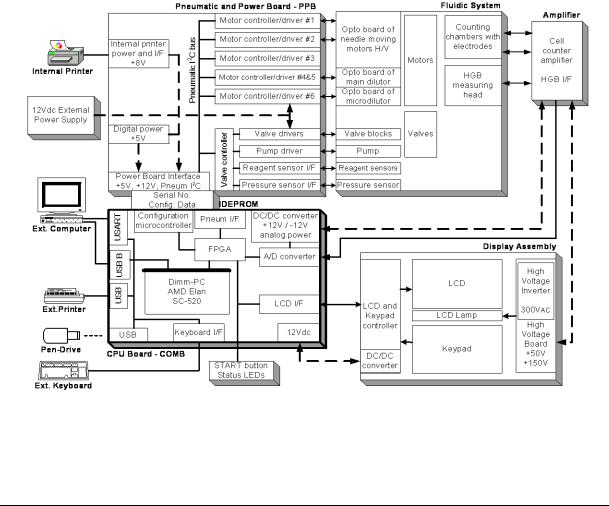
2.FUNCTIONAL DESCRIPTION
2.1.Main electronic parts of the analyzer
Abacus+ contains the following electronic parts:
1.Counting chambers with electrodes and measuring apertures
2.HGB Measuring Head
3.Cell Counter Amplifier Board (behind the chambers)
4.CPU Board with DIMM-PC and measurement processing unit (COMB Board)
5.Pneumatic and Power Board (PPB) with motor controllers, valve & pneumatic controller, pump driver and power supply for internal printer (+8V) and digital circuitry (+5V)
6.Safe configuration E2PROM board connecting CPU board and PPB
7.Motors with common opto-board of needle moving motors (H/V)
8.Main dilutor block with opto-board for diluent, lyse
9.Micro-dilutor block with opto-board for sampling
10.Valve boards (set of 5 and max. 7)
11.Peristaltic Pump
12.Pressure Sensor
13.Digital Reagent Sensor Board
14.Graphic LCD Display Module with High Voltage Board
15.LCD and Keyboard controller and Keyboard Panel
16.Internal Printer
Abacus+ Electronic Functional Block Diagram
rev 1.09

10 |
Diatron MI PLC |
2.1.1. Counting chambers with electrodes and measuring apertures
Impedance method is used for determination of volume and number of cells. In this method a known volume of dilution is drawn through a small aperture. Constant current is passed through the aperture from one side to the other. When a cell passes through the aperture, it causes a change in resistance, which generates a voltage pulse.
The amplitude of the voltage pulse is proportional to the ratio of cell volume per aperture volume. This is used to determine the volume of cells. The number of cells can be obtained by counting the pulses.
In the instrument there are two Cellcounter Probes: WBC probe with 100 μm aperture, and RBC probe with 80 μm aperture. Both have a ground electrode assembly and U-shaped metal fixing as it is shown in the next figure.
Assembled Cell-counter Probe |
Measuring tubes |
|
|
Red rings mark measuring tubes: One: RBC – 80 μm Two: WBC – 100 μm
O-ring
U-shaped metal fixing
Measuring tube Reference electrode
The aperture is made of ruby and it is moulded into the measuring tube.
2.1.2. HGB Head
Hemoglobin head is placed on the two sides of the WBC chamber.
It contains: light source (LED) at 540 nm wavelength and Photo Detector (TSL235). The Photo Detector converts the light to frequency. The HGB concentration is a logarithmic function of this frequency measured by the FPGA circuit of the COMB card.
Connection to the amplifier
LED |
TSL235 |
rev 1.09
Abacus+ Service Manual |
11 |
|
|
|
|
The analyzer performs enhanced Hemoglobin measurement technology for HGB measurement. The output of HGB head is frequency (TSL235 detector is light to frequency converter). This signal is counted by a digital counter in the FPGA circuit/micro-controller.
This counter counts up while the LED is on and counts down while the LED is off, the LED and the counter directions are switched with a 100 Hz signal. This method provides “real time backlight correction”, which makes the HGB measurement more precise in changing backlight environment situation as well.
There are two kinds of HGB measurements: |
|
Sample measurement |
(before RBC counting) |
Diluent measurement |
(in WBC washing phase) |
The HGB result is calculated from these measurements by:
HGB log (CNTdiluent light / CNTsample light)
In spite of the fact that Abacus+ is less sensitive to incident light changes it is recommended to keep side door closed during measurements.
2.1.3. Cell counter Amplifier Board
Amplifier board includes its own voltage regulator, the connection interfaces to HGB head, to high voltage board and to COMB card. In this board there is the current generator circuit, which works from 50 V measuring voltage (generated by High Voltage Board) and the probe voltage (DC) is amplified with a voltage follower (output: ELV). Nominal measuring current is
870 µA.
Amplifier board includes two input connectors for the chambers (measuring electrodes). There are two reed relays on the input side: IC10 can select between the two channels (RBC, WBC) with RSW signal; IC11 connects high voltage to the selected probe with HSW signal. Test circuit makes possible to generate test pulses (with TEST and PLS signals through FETs) for checking the proper operation of the amplifier channel.
Connection to the HVB |
Reed relays |
Connection to COMB (AMP and DIGIO) |
rev 1.09
12 |
Diatron MI PLC |
Amplifier board includes a 3-stage main amplifier channel, which gains to the input signal to the 0...5 V range (this is the input range of the A/D converter, which is placed on the COMB card). There is an offset potentiometer, P1 in the third amplifier stage, manufacturer sets the correct offset voltage.
Adjust the offset voltage only in case it is out of the +/- 5mV range.
DHON signal (from the COMB card) switches on the LED in the HGB head via a transistor (Q3), but the Photo Detector in the HGB head is working continuously.
The other side of the amplifier board contains special connectors for the chambers and the HGB head.
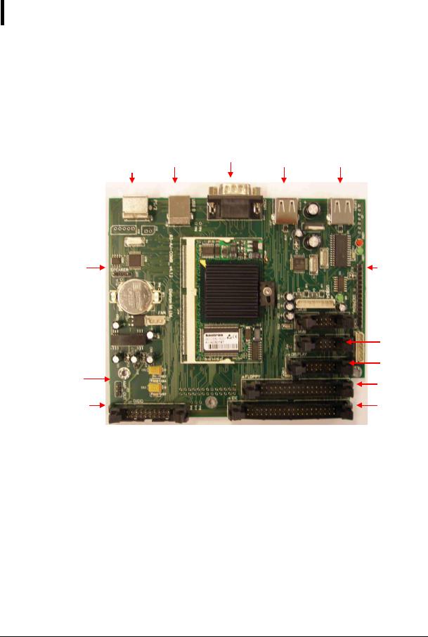
2.1.4. Control and Measurement Board (COMB) with DIMM-PC core
The compact COMB incorporates a single PC and its environmental functions, as well as the specific measurement processing functions in one board.
PS2 |
USB B |
COM 1 |
USB |
USB |
keyboard |
|
|||
|
|
|
|
Speaker |
IDEPROM |
connection
|
HVB |
|
|
connection |
|
Amplifier |
Display |
|
connection |
||
connection |
||
Floppy |
||
|
||
|
connection |
|
DIGIO |
IDE |
|
|
connection |
PC system of the COMB board is based on the DIMM-PC module, which is a credit card size PC with AMD Elan SC520 133 MHz micro-controller. DIMM-PC itself contains 16 or 32Mbyte RAM and same size of FlashDisk that acts like a hard disk. DIMM-PC module is easily replaceable as it has an open socket (it has also a screw for safe fixing). COMB card contains single ICs and some drivers/protection-circuits for the interfaces such as COM1, PS2, USB, IDE and Speaker.
Measurement processing is based on a FPGA circuit. After power on, the FPGA holds the DIMM-PC in wait state (with –IOCHRDY signal) until the PIC configures the FPGA circuit from the IDEPROM (status LED is red during configuration). After that the FPGA controls the entire pneumatic system through the Pneumatic I2C bus, the Keyboard and Display module with video RAM for MDA (Monochrome Display Adapter) emulation, and Start button & status LED. FPGA circuit also performs measurement data acquisition by using the 10-bit A/D chip. FPGA makes digital data processing and stores the results in the internal FIFO memory. Cell parameters are sent to the DIMM-PC by single DMA cycles.
rev 1.09
Abacus+ Service Manual |
13 |
|
|
|
|
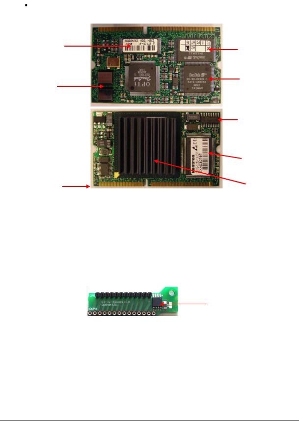
2.1.5. DIMM-PC* Module
The MB4 board incorporates a credit-card sized PC, named DIMM-PC*. The processor on the DIMM-PC is a 133MHz Pentium-class core, with 32Mbytes on-board RAM, and 32Mbytes on-board FlashDisk. This is the HDD (hard disk drive) of the analyzer, so instrument software with all user settings, calibration, database, etc. is stored on the DIMMPC.
DIMMPC® is the Trade Mark of Kontron Embedded Modules GmbH
Flash BIOS
32 Mbytes RAM
On-board SMPS 
Edge connector
2.1.6. Configuration and ID E2PROM board (IDEPROM)
Hard Disk (FlashDisk)
FlashDisk
controller
Clock generator
Super I/O
AMD Elan
SC520 CPU
This board is the interconnection between COMB and PPB cards: Pneumatic I2C bus, power lines and internal printer signals are connected through this card. The board also contains a 24FC256 serial E2PROM, which stores the FPGA‟s configuration data and identity information of the instrument (Serial Number, OEM, model, etc.).
E2PROM
Keeping the hardware identity information (write-protected), IDEPROM allows running the correct software.
rev 1.09
14 |
Diatron MI PLC |
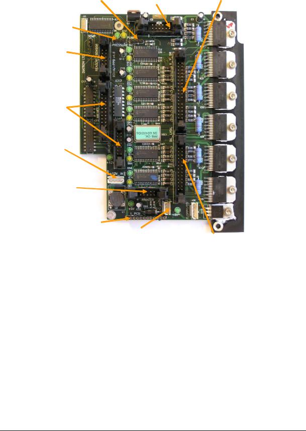
2.1.7. Pneumatic and Power Board (PPB)
PPB card contains the main power regulator circuits, valve and motor driver circuits and other connections for the fluidic and pneumatic system‟s parts.
PUMP Peristaltic pump connection
PRESSURE Pressure sensor connection
REAGENT_SENSOR Reagent sensor connection
VALVES
Valve connections
+12V_IN Power input
PRINTER
Internal printer connection
I_PCB_CONNID board connection
MDIL
Micro dilutor connection
5V voltage regulator (on chassis)
X_Y_SR
Horizontal, Vertical & Sample rotor connection
FLOPPY/CD
Power to
Floppy/CD DIL_MDIL Main Dilutor
connection
PPB card contains the main power regulator circuits, valve and motor driver circuits and other connections for the fluidic and pneumatic system‟s parts.
Power system generates +5V (Digital power), +8V (Printer power) and +12V (Motor and valve power) from the single +12V DC input signal.
Motor driver part consists of six separated PIC micro-controllers with power drivers. Horizontal, Vertical and Sample rotor motors have one combined ribbon cable connection. Main Dilutor (with two motors) and Micro-dilutor have separated connectors.
Valve driver section is based on the valve driver PIC micro-controller and three 8-bit, powered output shift registers (with built in protection diodes) and there are two common ribbon cable connections for the 4 valve boards. The peristaltic pump has a separated Darlington driver circuit for more reliable operation.
All the 7 (6 for motors, 1 for pneumatic) microcontroller have 2 LEDs: a yellow one and a green one.
The yellow one indicates motor moving or holding and active valve or pump moving. (it means current flows into motors, valves or pump)
rev 1.09
Abacus+ Service Manual |
15 |
|
|
|
|
The green one has 3 states:
dark: (after initialization phase) error state,
blinking: communication in progress - normal state
on(just lighting): OK - normal state
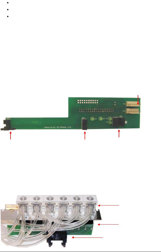
2.1.8. Opto-boards for stepper motors
There are five stepper motors in the system: Horizontal and Vertical motors, which make the movements of the sampling needle; the main Dilutor motors (2), which move the syringes and the micro Dilutor motor, which drives the sampling phase. The stepper motor opto boards make the connections between the motor driver ICs and motors, and have opto switches for the motor‟s home and end positions. The actual status of the stepper motor‟s optos is indicated by two LEDs on each stepper motor opto boards.
Dilutor and Micro-dilutor have its own separated opto-board, located directly in the units. Horizontal and Vertical motors have a common Opto-board, called XYopto Board:
Connections for Hoirizontal &
Vertical motors
Opto switches & LEDs for Horizontal motor |
Opto switches & LEDs |
|
for Vertical motor |
The other side of the board contains a ribbon cable connection to the COMB.
2.1.9. Valve boards
There are two kinds of valve boards: Valve board 0-5 and Valve board 6-12.
The valve boards are connected to controller and driver chips are located on the PPB.
Valves
Valve Board
Connection to PPB
rev 1.09
16 |
Diatron MI PLC |
2.1.10. Pressure Sensor
This is an MPX5100AP calibrated pressure sensor, which can measure the required air pressure and vacuum. The Pressure Sensor is connected directly to the PPB card.
 Connection to Puffer reservoir
Connection to:
PPB
The pressure sensor can operate from +5V only. It is a calibrated sensor with 0-1.1 Bar input range. Do not apply more than 1.5 Bar to it, because it can ruin the pressure sensor.
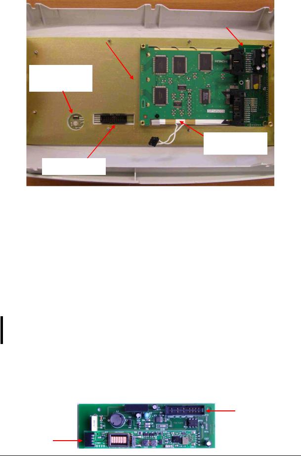
2.1.11. Digital Reagent Sensor Board
This board contains four liquid detector opto-detectors (optos) and a reference opto for automatic temperature and stray light compensation. The reference opto is located in the middle and it has the same temperature and backlight conditions as the sensing ones.
Reference detector
Control LEDs |
Reagent detectors |
The Reagent Sensor Board is connected to the PPB card, and the valve driver microcontroller makes the sensing and compensating operations.
Instrument makes automatic initialization – called calibration – of reagent sensors during priming phase of fluidics.
rev 1.09
Abacus+ Service Manual |
17 |
|
|
|
|
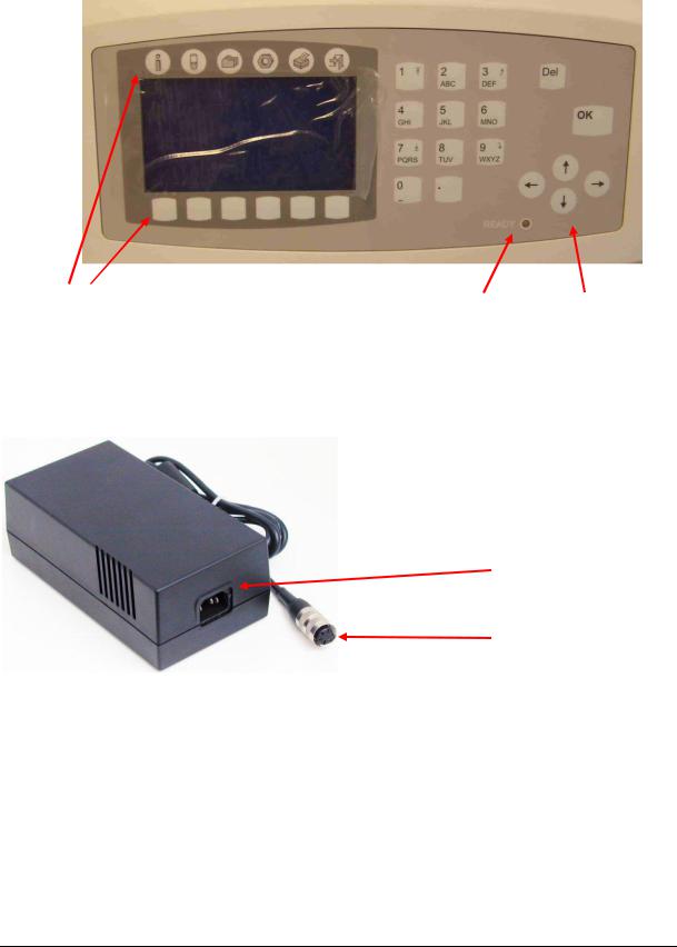
2.1.12. LCD Display Module with High Voltage Board
|
|
LCD & |
|
|
Keypad |
|
|
controller |
LCD module |
|
|
|
|
|
|
|
|
|
|
|
Start key connection and status LED
LCD backlight lamp
Keypad connector
Display assembly contains the 240x128 dots graphics LCD display and the high voltage board. LCD has a high voltage backlight lamp (high voltage board generates the required voltage).
There is a special temperature compensation circuit in the display module, which makes possible to use the LCD module in wide temperature ranges with the adjusted contrast.
High Voltage Board (HVB) generates LCD backlight voltage (300V), aperture cleaning voltage (150V), and measuring voltage (50V). The high voltage board is connected to the system through the amplifier board and the COMB card. This unit contains INVC191 inverter, which is a high voltage, high frequency circuit producing suitable voltage for CCFL (cold cathode fluorescent lamp) of the LCD.
The CFSW digital signal (from the COMB card) controls HVB: logical LOW turns inverter on. The MVON digital signal (from the COMB card) switches the measuring voltage (50 V) on/off by O1 opto switch.
Warning! Be careful with servicing this board in active state, because the high voltage (300V) at LCD lamp connector can cause damages or electric shock.
Start key is a micro-switch, connected to the COMB card (through the Display ribbon cable). The status LED indicates the actual status of the analyzer and it has two colors: red and blue
(See User‟s Manual). The LED has three pins and the actual color depends on the controlled pins. Start key and status LED are controlled by COMB.
Connection to COMB and amplifier
Connection to LCD lamp
rev 1.09
18 |
Diatron MI PLC |
2.1.13. Keypad
The analyzer has a 29-button foil keypad including numerical keypad (0-9, “.”), cursor moving, OK and Del buttons, and 6-6 function buttons, above and under the LCD display as it is shown in the picture below:
Function buttons |
Status LED |
Cursor buttons |
2.1.14. External Power Supply
The analyzer works with an external power supply. The next figure shows the power supply unit generating 12VDC.
115V or 230V AC inlet
12V DC outlet
The power supply modules have an auto range input, which makes possible to use them with 230V or 115V mains outlet and it has the CE and UL safety certification. The input socket of the power supply is a standard 3-terminal plug, with power cable connection; the output is a special, lockable socket as it is shown in the picture.
rev 1.09
Abacus+ Service Manual |
19 |
|
|
|
|
2.2. Main mechanic and fluidic parts of the Analyzer
Abacus+ Hematology Analyzers consist of the following mechanic and fluidic parts:
1.Sampling needle
2.Washing head
3.H&V moving unit
4.Micro Dilutor
5.Dilutor
6.Chambers
7.Cell-counter probes
8.Puffer reservoir
9.Pump
10.Valves
11.Tubing
rev 1.09

20 |
Diatron MI PLC |
2.2.1. Sampling needle
Sampling needle is assembled in the H&V moving unit and it makes the sample aspirations. Correct setting of sampling needle is necessary and very important (see Chapter Adjustments).
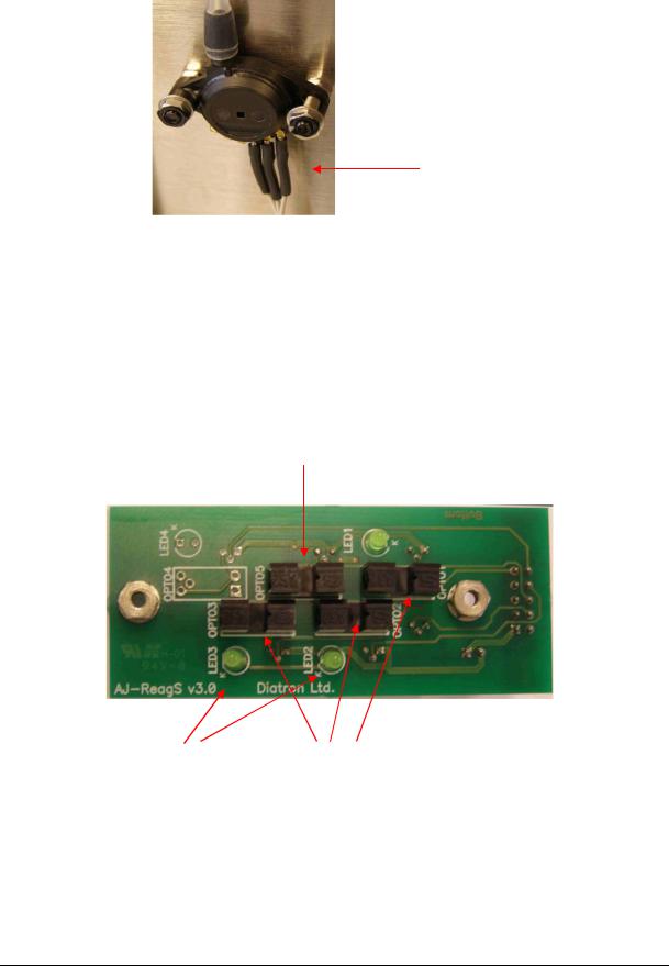
2.2.2. Washing head
Washing head is located at the bottom of the H&V moving unit and it is for cleaning the outer surface of the sampling needle. This washing process is made with diluent reagent and the fluid is drained by the pump. The arrows on the picture show the direction of diluent flow during sampling needle washing.
Clean diluent
Pump to waste
Clean or replace washing head yearly, or after 10 000 measurements.
rev 1.09
Abacus+ Service Manual |
21 |
|
|
|
|
2.2.3. H&V moving unit
This unit contains slides to move the sample sampling needle in Horizontal and Vertical directions, two stepper motors, XYR opto board, opto wheel, washing head and the sampling needle. It moves the needle to the desired position: from sampling position, to washing head, and to the measuring chamber.
Sampling needle holder
Sampling needle |
|
XYR opto board |
Vertical opto wheel |
|
|
|
|
|
|
|
|
Washing head
Vertical
motor
Horizontal
motor
Both stepper motors have optical end-switch sensors for detecting these positions. These are required for correct initialization and error detection. All sensors have status LEDs to show actual conditions.
The Vertical motor works with a special opto wheel for detecting home & end positions. See the Adjustment section of this manual to place this wheel to the proper position.
Greasing of the horizontal/vertical guiding rods should be done regularly using “Photolube” (A598), a PTFE-based thin lubricant.
It is recommended to check and repeat greasing of guiding rods every year, or after 10000 measurements.
rev 1.09
22 |
Diatron MI PLC |
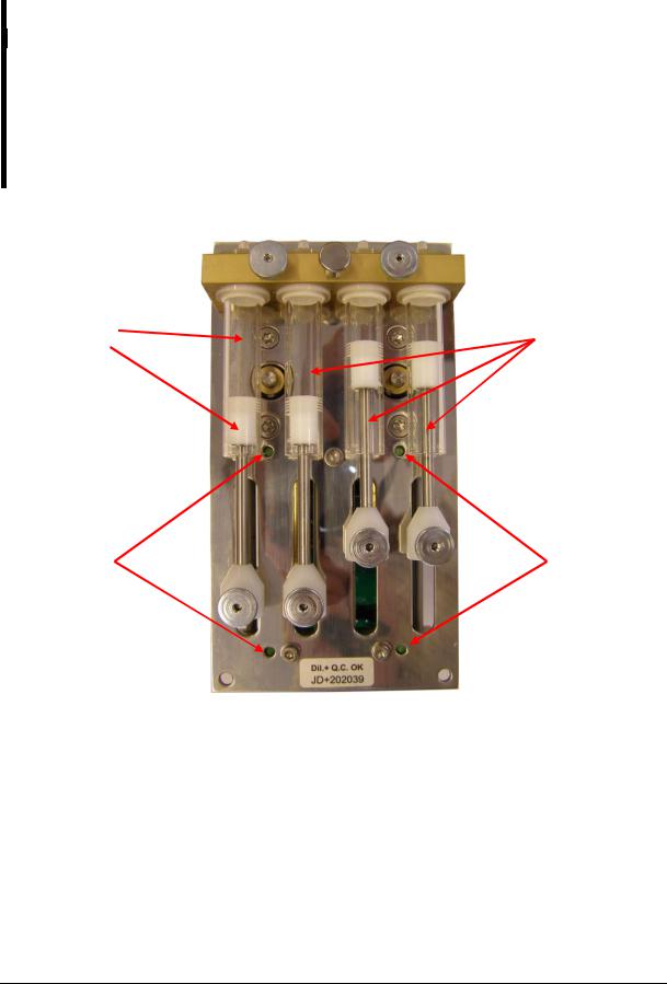
2.2.4. Main Dilutor
There are two stepper motors, a common motor opto board, four syringes and piston rods with gear transmission.
Maintenance should be provided to the piston tips, by applying neutral silicon grease to the cogged end of the Macro and Lyse pistons, between the syringe and the tip itself. This will ensure optimum sealing and longer lifetime of piston tips.
Greasing of the cogged transmission parts (cogwheel and cogged bar) should be done regularly using machine grease.
It is recommended to check and repeat greasing of piston tips, and transmission gear every year, or after 10000 measurements.
Lyse syringe and |
Diluent syringes |
|
piston |
||
|
Control |
Control |
|
LEDs |
||
LEDs |
||
|
rev 1.09
Abacus+ Service Manual |
23 |
|
|
|
|
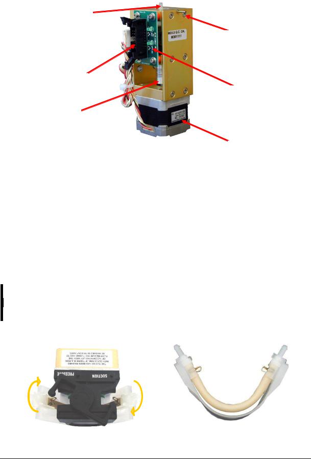
2.2.5. Micro Dilutor
Micro dilutor is taking the precise sample (25 or 50μl) into the sampling needle. It includes a stepper motor, a motor opto board and the micro syringe.
Connection to Valve
Connection to sampling needle
Connection to PPB
Motor opto board
Flexible clutch
Stepper motor
2.2.6. Puffer reservoir
The glass puffer reservoir is directly connected to the pressure sensor.
During measurement, there is no pump activity, so the puffer reservoir maintains measuring vacuum stable. The instrument measures atmospheric pressure and adjusts measuring vacuum according to it.
2.2.7. Pump
Pump generates regulated vacuum and drains the fluidic system. It is connected to the PPB and it has its own driver circuit (Darlington).
If the tube of the peristaltic pump becomes worn, it can be broken, causing Pressure error.
It is recommended to check the state of the tube, and replace it every 2 years, or after 20 000 measurements. Always replace the peristaltic pump tube to the same
PharMed® type, with the same length.
For servicing the tube of the pump, open the peristaltic pump from its top (see picture) and remove the tube together with the white plastic side wall (see picture):
In case of damaged tubes, it can be replaced by a new one by opening the two metal locks located at the two ends of the tube (see picture).
rev 1.09
24
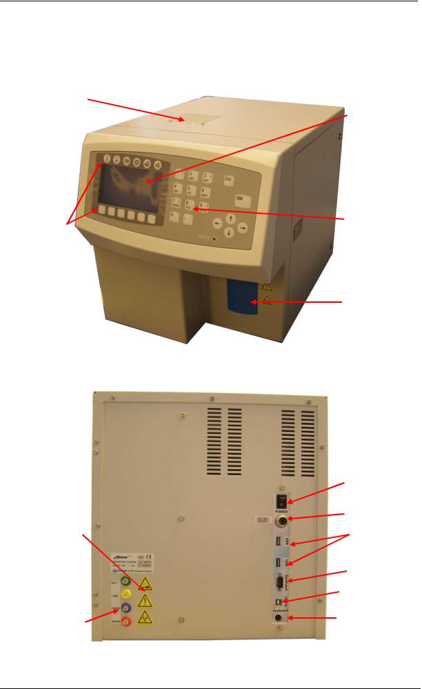
2.3. Assembled Analyzer
2.3.1. Abacus+
Front Panel
Built-in thermal printer (optional)
Function keys
Rear panel:
Warning labels
Reagent inlets
Diatron MI PLC
240x128 dots Graphic LCD
Foil keypad
START button
Power switch
12V DC inlet
USB ports
Serial Port
USB slave port
PS/2 external keyboard port
rev 1.09

Abacus+ Service Manual |
25 |
|
|
|
|
Construction – front:
Valve block
Pressure
sensor
Electronic
block
H&V unit
Speaker
Valve block
Construction – right side
:
Valve block
Needle moving
mechanics  Reagent sensor
Puffer reservior
|
Microdilutor |
|
|
Measuring |
|
chambers |
Pump |
|
|
Valve block |
Dilutor block |
rev 1.09
26 |
Diatron MI PLC |
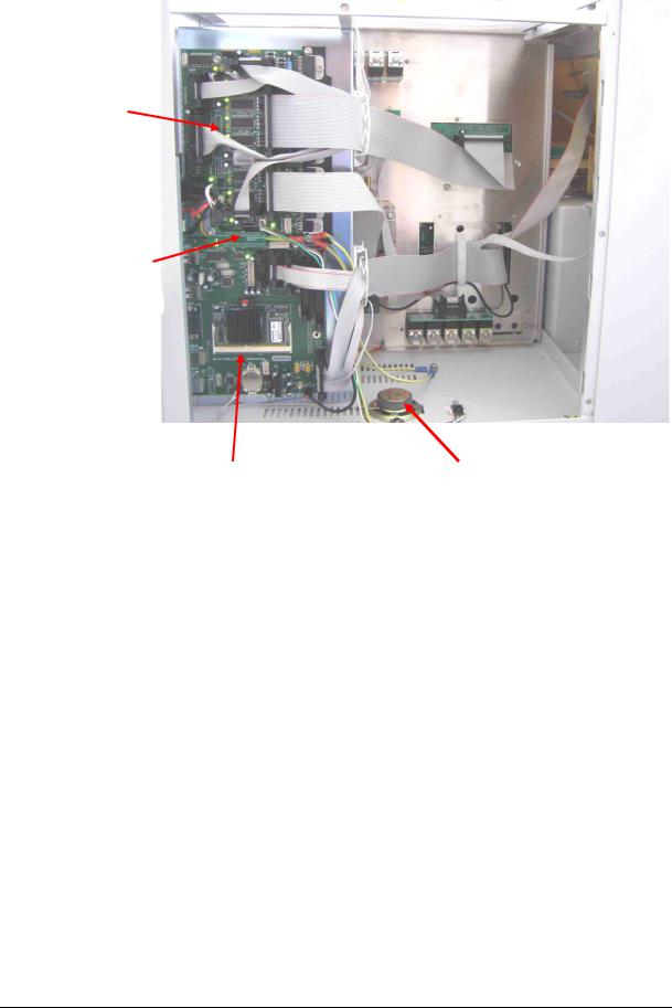
Construction – left side:
Pneumatic and
Power Board
(PPB)
ID Eprom Board
(IDEPROM)
Control and |
Speaker |
Measurement Board |
|
(COMB) |
|
rev 1.09
Abacus+ Service Manual |
27 |
|
|
|
|
3.ADJUSTMENT
Mechanical and hardware adjustments are described in this section. Software settings are included in Section 5.2.
3.1. Mechanical settings
There are two important mechanical settings in the system:
 Opto wheel setting (Vertical motor)
 Sampling needle setting
The manufacturer adjusts the analyzer during production. However, in case of repairs in the mechanical system, these adjustments should be checked. The omission of these settings can cause malfunction or damages to the instrument.
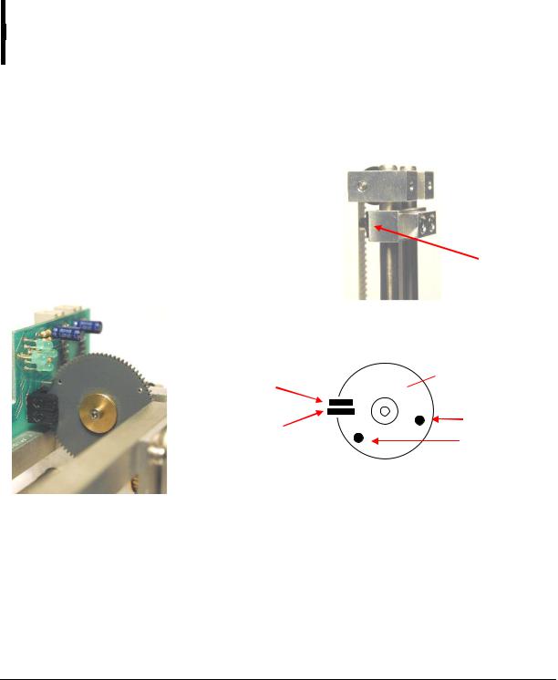
3.1.1. Opto wheel setting
This setting is necessary for the vertical motor movements because this adjustment sets the opto end-switches of the H&V moving unit. The top of this block is called HV head and it is shown in the figure below.
Set the distance to 1-2 mm between the moving carriage and the stable part of the head.
Loose „A” screws to allow free movement of the timing belt.
Adjust the opto wheel to home position, i.e. home hole must be in home sensor, and LED corresponding to home opto sensor goes on.
Fasten „A” screws.
 Screw „B”
Screw „A”
Opto wheel
End opto
End hole
Home opto
Home hole
Check the end position as well: move the needle down. Adjustment is successful if end LED goes on before moving part reaches end of mechanical range.
Once this adjustment is necessary, never miss sampling needle setting described in the next section.
rev 1.09
28 |
Diatron MI PLC |
3.1.2. Sampling needle setting
This adjustment sets the sampling needle to the operational position.
In Service menu, in Miscellaneous submenu of AJ/AJvet and in Service menu of AJB select
Needle setting.
The software moves the needle back and up, and turns on horizontal and vertical motors (AJ/AJvet) to keep needle in place. AJB holds only the vertical motor during needle setting.
|
|
|
|
|
|
|
|
Sampling needle |
Bottom plane of |
|
|
|
|
|
|
|
Teflon stuffing ring |
washing head |
|
|
|
|
|
|
|
|
|
|
|
|
|
|
|
|
|
|
|
|
|
|
|
|
|
Tubes to/from the |
|
|
|
|
|
|
|
|
|
|
|
|
|
|
|
|
|
washing head |
|
|
|
|
|
|
|
|
|
Check the setting of the needle. If end of the needle is at the bottom of the washing head, needle is set correctly. If not, open screws “B” (see above), and adjust the needle to the bottom of the washing head. Fasten “B” screws.
Set the end of the tip to the washing head’s bottom plane, while the carriage is held by motors. (Needle setting menu). Fix the „B” screws.
Be careful with the bent upper end of the sampling needle, because if badly aligned, during movement it can hit other mechanical components causing mechanical jam, and therefore damages or error.
3.2. Hardware settings
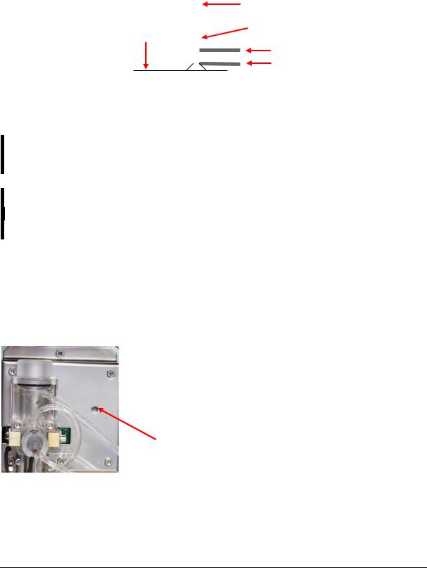
3.2.1. Amplifier offset setting
Amplifier offset should be between ±5mV. Run self test to determine whether offset is within this range. If it is out of range, it should be re-set, by the following way.
1.Locate the opening for offset setting potentiometer on the measuring block (see enclosed picture).
2.In Service menu select Offset adjustment menu.
3.Adjust the potentiometer to reach 0 mV.
Opening for offset adjustment on measuring block
rev 1.09

Abacus+ Service Manual |
29 |
|
|
|
|
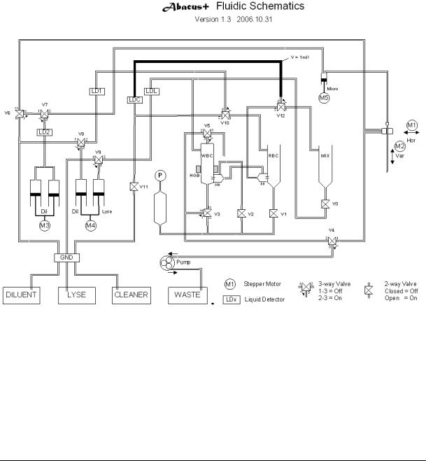
4.OPERATION OF THE FLUIDIC SYSTEM
This section describes the main steps of Abacus+ fluidic functions. The instrument‟s Fluidic Schematics are shown in section 2.2 of this manual. The following figures show total measurement flow diagram and detailed descriptions of basic processes for understanding the fluidic system work.
The following steps are introduced in this section:
1.Basic processes
1.1.Sampling process
1.2.Needle washing process
1.3.Diluting process
1.4.Fluid transfer from MIX chamber to WBC chamber
1.5.Lysing process
1.6.Counting process
1.7.Aperture priming process
1.8.WBC chamber draining process
1.9.RBC chamber draining process
1.10.Cleaner priming process
2.Main functions of the fluidic system
2.1.Initialization
2.2.Wake up
2.3.Measurement cycle
2.4.Standby
2.5.Cleaning
2.6.Hard cleaning
2.7.Shutdown
In the detailed process description figures, the active tube is filled with black or gray color, while an arrow ( ) shows the direction of the flow. Moving mechanic parts have another arrow indicating direction of movement. In the section of the basic processes only relevant valves are mentioned in this section (ON or OFF) while all the other valves are in either ON or OFF state depending on the status of the instrument and other parallel running process.
Abacus+ employs a software waste full checking feature. Software integrates volume of the reagents used.
rev 1.09

30 |
Diatron MI PLC |
4.1. Basic processes
4.1.1. Sampling process
The aspirating needle aspirates 25 µl (50 µl in prediluted mode) of blood sample. The Microdilutor syringe makes the aspirating while the M5 Micro-dilutor motor moves down.
There is another sampling process for the second (RBC) dilution, when 35 μl of primary dilution is aspirated from the MIX by the aspirating needle. Both of the samples are separated from the diluent with a small air bubble and there is another air bubble between the sample and the end of the needle.
rev 1.09
 Loading...