


Better Air is Our Business
®
Read and Save These Instructions!
NOTE: 1. Read and understand all operating instructions before
installing and using the SAAFShield Detecting Unit
Real-time Reactivity Monitor.
2. Save this manual for future reference.
This instruction manual provides important information on the
installation and operation of the SAAFShield Detecting Unit Real-time
Reactivity Monitor. These instructions must be carefully followed in
order to operate the unit safely and correctly. If there are any
questions regarding the use or care of this unit, please contact
AAF at 888-AAF-2003 or by email at SAAFShield@aafintl.com for
assistance.
Detecting Unit Real-time Reactivity Monitor
Installation, Operation, and
Maintenance Instructions
Table of Contents
1.0 Principles of Operations
2.0 Components
3.0 Installating Quartz Crystal Microbalance (QCMs)
4.0 Installing the Detecting Unit
5.0 Troubleshooting
6.0 Connecting to the Reading Unit
7.0 Spare Parts List
1.0 Principles of Operation
The SAAFShield Detecting Unit is the non-powered, sensing side
of the SAAFShield system that utilizes Quartz Crystal Microbalance
(QCM) technology to measure metal corrosion due to reactions
with the environment. The SAAFShield Detecting Unit works in
combination with the SAAFShield Reading Unit as part of a system
that monitors atmospheric corrosion in real-time or on a periodic
basis.
The SAAFShield Detecting Unit’s oscillator Printed Circuit Board
(PCB) consists of specially marked tracking where electromagnetic
induction effects are significantly reduced in order to produce the
most stable and accurate frequency reading. As the metal-coated
QCM corrodes, the frequency of oscillation changes. The Detecting
Unit has built-in non-offgassing EVA foam spacers to prevent
unwanted movement of the QCMs within the enclosure.
2
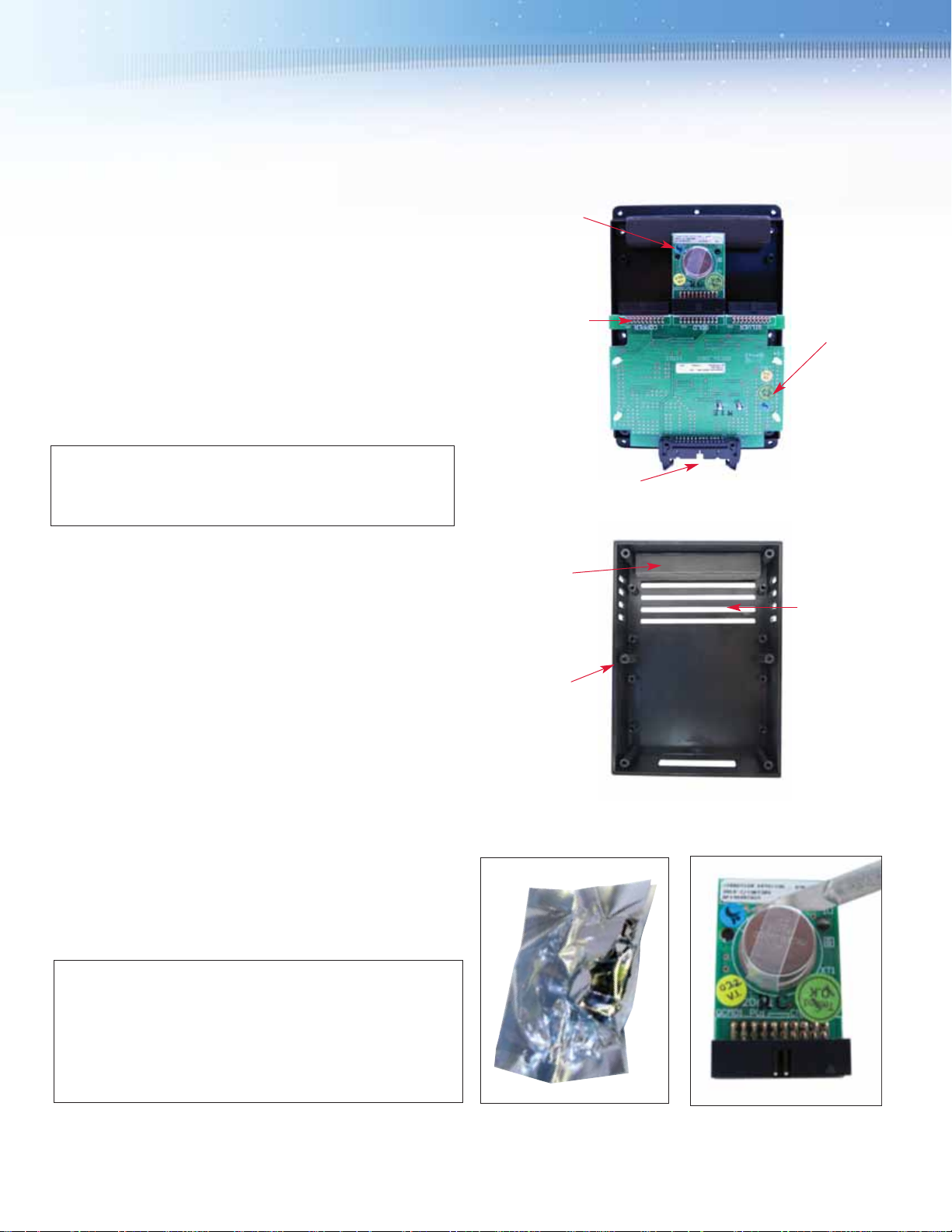
Figure 1 — SAAFShield™Detecting Unit with internal components labeled
Cutouts for
airflow
Outside casing
EVA foam
spacers
2.0 Components
Figure 1 shows the SAAFShield Detecting Unit with the internal
components labeled.
The SAAFShield Detecting Unit Real-time Reactivity Monitor includes
the following components:
• (1) Oscillator Printed Circuit Board (PCB)
• (3) Connector slots for Quartz Crystal Microbalance (QCM) PCBs
• (1) Black plastic thermoplastic case with airflow zones and
protective cage
• (1) Connector slot for interfacing with the SAAFShield Reading
Unit
• (3) QCM PCBs (packaged separately)
IMPORTANT: To open the QCM PCB package prior to installation,
please carefully follow the instructions supplied below. Mishandling
the QCM PCB can cause irreparable damage.
Ribbon cable connector slot
(connects to Reading Unit)
Oscillator
PCB
Connector slots
(connects to QCM-PCB)
QCM PCBs
3.0 Installing Quartz Crystal Microbalance (QCM)
Tools Required:
• Philips head screwdriver
• Scissors, exacto knife, or razor blade
Instructions:
1) Ensure that the Electrostatic Discharge (ESD) protected bag
contains the appropriate QCM (Gold, Silver, Copper) that you would
like to install. See Figure 2.
2) Carefully cut open the ESD bag and remove any protective
packaging around the QCM PCB.
3) The QCM-PCB has a protective black foam backing – do not
remove this foam.
4) You will need to remove the plastic protective banding from the
QCM to expose the reactive elements on the QCM. Carefully cut one
end of the plastic protective banding as shown in Figure 3 with a razor
blade or exacto knife.
CAUTION. In some instances, the plastic band material may be tightly
adhered to the metal cap. This is done to provide a tight seal on the
cap and ensure complete protection of the QCM reactive element
during shipment. Please do not force open the metal cap. Doing so
may cause irreparable damage to the QCM’s reactive element within
making the device non-operational. It is advised that the metal cap be
gently removed from the QCM and handled carefully at all times.
Figure 3
Figure 2

5) Cut the other end of the plastic band off using care with a razor
blade, exacto knife, or scissors. It is not necessary to remove all the
plastic band material from the PCB. It is sufficient if the cap is
removable to expose the QCMs reactive element. See Figure 4.
6) The metal cap for the QCM can now be removed as shown in
Figure 5.
7) Insert the QCM-PCB in the appropriate slot as marked on the
Oscillator PCB of the SAAFShield Detecting Unit. See Figure 8.
8) Repeat steps 1-7 for each QCM-PCB.
9) Once all 3 QCM-PCBs have been installed, verify that they are
installed in the appropriately marked slot.
10) Install the outside casing using the 6- screws provided. See
figures 7.
3
Figure 4
Figure 5
Figure 6 - SAAFShield™Detecting Unit with Gold QCM installed
Figure 7 - SAAFShield™Detecting Unit with QCMs and cover installed
4.0 Installing Detecting Units
When determining the reactivity of a room or space within a building,
the SAAFShield Detecting Unit should be placed in a location
representative of the air that contacts the electronics or materials
being protected. This will depend on the setup of the room. If the
protected items are spread out within the space, then an approach
similar to a thermostat should be used. If the protected items are
concentrated in one area inside the space, then a location as close
as possible to them is preferred.
The number of locations inside the control room will depend on the
airflow properties in the space. If the HVAC system mixes the air in
the space very well and it is a small space, then one unit may be
acceptable. If the room has poor air mixing with one location getting
hot while others stay cool, then more than one will be needed. Find a
location which represents the average condition of the air that
contacts the electronics or materials being protected.
When determining the condition downstream of a gas-phase filter or
scrubber to evaluate media performance and life, the SAAFShield
Detecting Unit should be placed after the final particulate filter.
5.0— Troubleshooting
When is it time to replace the QCMs?
Check the sensor life remaining of the QCMs using the SAAFShield
Reading Unit in order to determine the remaining life for each sensor.
What if a connector slot breaks or is not connecting?
In the event that a connector slot breaks or is not connecting, please
contact your AAF sales representative immediately.
What if the sensors break?
In the event that a OCM sensor breaks, please contact your AAF
sales representative. If there is physical damage on the QCM sensor,
the SAAFShield units will not function.

10300 Ormsby Park Place Suite 600
Louisville, Kentucky 40223-6169
www.aafintl.com
Customer Service 888.AAF.2003
Fax 888.223.6500
AAF has a policy of continuous product research and
improvement and reserves the right to change
design and specifications without notice.
ISO Certified Firm
© 2011 AAF International
The USGBC Member logo is a trademark owned by the
U.S. Green Building Council and is used by permission.
GPF-3-116 NOV ‘11
Detecting Unit Real-time Reactivity Monitor
SAAFShield Reading Unit
7.0 Spare Parts List
It is recommended that the following spare parts be stored at the installation site for replacement purposes. Consult with your AAF
representative to determine actual quantities required. Minimum recommended quantities are provided in the table below.
AAF Part Number Description Recommended Spares
392-803-010 Silver Crystal QCM One full replacement set of each type
included in the system.
392-803-011 Gold Crystal QCM One full replacement set of each type
included in the system.
392-803-012 Copper Crystal QCM One full replacement set of each type
included in the system.
To order replacement parts call: 1-800-AAF-2003.
6.0— Connecting to the Reading Unit (RU)
When inserting QCMs for the first time, the RU will automatically
default to the ‘Edit QCM Info’ window and force the user to enter
information regarding QCM parameters. Be prepared to enter this
information when installing a new QCM. See bulletin GPF-3-117.
The Information that will be needed when initializing the Gold, Silver,
and Copper QCMs is:
• Site ID
• Room ID
• Detecting Unit ID
• Detecting Unit installation location information (upstream,
downstream, or in-room)
The Initialization frequency and install date and time will be
automatically recorded by the RU.
 Loading...