


Better Air is Our Business ®
OptiFlo® Pulse-Jet
Cylindrical Cartridge
Dust Collector
Installation, Operation, and
Maintenance Instructions
Table of Contents
1.0General Information
1.1Filter Elements
1.2Normal Operation
1.3Sizes
1.4Factory Assembly
2.0General Information
2.1Inspection
2.2Installation
3.0 |
Foundations and Anchoring |
4.0 |
Ductwork and Accessories |
5.0 |
Electrical Controls and Wiring |
6.0 |
Compressed Air Connection |
7.0 |
Gauge Installation |
8.0 |
Filter Installation |
9.0 |
On-line Cleaning |
10.0 |
Initial Start-Up Instructions |
10.1Maintenance
11.0Troubleshooting
11.1High Pressure Drop Reading
11.2Visible Discharge
11.3Insufficient Hood Control
The OptiFlo® pulse-jet cylindrical cartridge collector is a factory assembled, automatic self-cleaning dust collector. It uses a modular building block concept to meet any airflow capacities and design requirements. This bulletin contains the information necessary for installation, operation, and maintenance of the OptiFlo dust collector. Read the entire manual and check each carton and crate against the shipping sheet (Form 1281) before beginning installation.
1.0 General Information
WARNING: In the event this unit is not placed in service within 60 days after receipt, the filter cartridges must be removed and stored in a clean, dry place to prevent possible moisture accumulation in the media.
1.1 Filter Elements
The basic filter element used in the OptiFlo dust collector is the OptiFlo cartridge filter. The OptiFlo filter consists of pleated media in a cylindrical configuration. This design allows for installation and changeout with a minimum of time and effort. Each OptiFlo filter is supplied with its own gasket to ensure a positive, airtight seal each time the filter is changed.
The filters are installed horizontally. Filters are cleaned automatically in sequence, so that only a small portion of the filters are off-line at any given time.
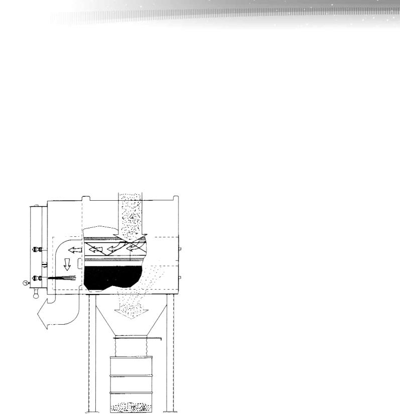
1.2 Normal Operation
During normal operation (See Figure 1), air enters the OptiFlo dust collector through the inlet and passes through the filter elements. Dust is collected on the outside surfaces of the elements and clean air flows through the center of the elements into the clean air plenum, in true “downflow” fashion, where it exits through the clean air outlet.
During filter element cleaning, a solid-state control timer automatically selects the element or pair of elements to be cleaned, activating solenoid valves which open air diaphragm valves. High pressure air pulses directly into the center of the selected element, or pair of elements, for 100 milliseconds, blowing collected dust off the filter element(s). The dust is swept downward into the hopper by the prevailing airflow and by gravity.
Figure 1
NOTE: For multiple module units, an inlet in each module is mandatory to optimize performance.
1.3 Sizes
The OptiFlo pulse-jet cartridge collector is available in these basic configurations: 2RC, 3RC, 4RC, and 5RC series. All modules are two filter elements wide. Sizes 2RC4 and 3RC6 are one filter deep—all other sizes are two filters deep.
The 2RC modules have filters arranged two-high, 3RC modules have filters arranged three-high, 4RC modules are four filters high, and 5RC modules are five filters high. Each series offers standard factory assembled collectors with model designations such as: 2RC8; 2RC16; 2RC24; 2RC32; 3RC12; 3RC24; 3RC36; 3RC48; 4RC16; 4RC32; 4RC48; 4RC64; 5RC20; 5RC40; and 5RC60. The second number in the model designation indicates the total number of cartridges per collector.
1.4 Factory Assembly
All OptiFlo dust collectors are shipped in sub-assemblies requiring only:
•Field bolting of the hoppers, legs, and braces
•Connection of ductwork and/or the fan
•Mounting and wiring of the control box
•Connection of compressed air supply
•Differential and air pressure gauge connections
The collectors are shipped with filter elements installed. Units shipped as 4 or greater assembled modules are not skidded. Instructions for field assembly are given in subsequent sections.
The main housing is constructed of 7 gauge carbon steel. Each module is complete with pulse-jet piping, 1-inch diaphragm pulse valves, pilot solenoid valve control boxes, and 6-inch diameter externally mounted compressed air reservoir. The compressed air reservoir is provided with (2) 1 1 ⁄ 2 inch NPT pipe couplings for compressed air attachment and drain.
2.0Installation Instructions
2.1Inspection
The OptiFlo dust collector is normally shipped by truck and should be checked for any damage that may have occurred en route. Any damage should be noted and the carrier notified within 24 hours.
2.2 Installation
(See Figure 2 for Typical Installation, and Figures 6 and 7, back page for parts.)
A crane is recommended for unloading, assembly and installation of the OptiFlo dust collector. Stand hopper(s) on their discharge side (hopper outlet) and apply caulk to hopper flanges in a figure-eight pattern around bolt holes. Lift cabinet from the truck, position over hopper(s) and bolt cabinet and hopper(s) together with
3 ⁄ 8 " x 1 1 ⁄ 4 " thread cutting bolts, flatwashers, lock-washers, and nuts as shown on Bolting Detail - Hopper to Cabinet, back page.
2

Figure 2. OptiFlo Cartridge Collector Typical Installation
|
|
Diaphragm |
|
Solenoid |
Valve |
|
|
|
|
Enclosure |
|
|
Air Header |
|
|
Blow-Down Valve* |
|
|
Air Line to |
|
|
Manifolds* |
|
Air Regulator* |
Solenoid |
|
|
|
|
Air Filter |
Electrical |
|
Connection* |
|
|
(Bleed Type)* |
|
|
|
|
|
Air Valve* |
|
|
Air Supply Line*
Automatic
Condensate Valve*
Solid-State
Control Timer
Low Voltage (120 V AC) Magnetic
Starter (Blower Motor)*
WARNING:
•Connect lifting sling to at least four cabinet lifting lugs - distribute load equally.
•Connect lifting sling to double-thickness cabinet lifting lugs provided on collectors 3 and 4 modules wide. Always use spreader bars on collectors field assembled wider than
4 modules.
•Use clevices, not hooks, on lifting sling.
•Use of spreader bars is recommended on all lifting slings.
Attach legs — All legs are the same, however, they must be located in the proper position as shown in Figure 3. Also, leg crossbracing must be located as shown in Figure 3. Lift the entire cabinet/hopper assembly and attach legs with bolts (included), flatwashers, lockwashers, and nuts — do not tighten bolts. See Bolting Detail — Legs to Cabinet, back page.
WARNING: Do not disconnect crane or attempt to support cabinet on hoppers.
Lifting Lug
Air Manifold
Collector Fan Outlet*
Fan (Optional)
Magnehelic Gauge
Power Supply Disconnect Switch*
NOTE: These (*) items are not included with Dust Collector.
Attach leg crossbraces at rear of dust collector with included 5 ⁄ 8 " bolts, flatwashers, lockwashers, and nuts. See Figure 3 and Bolting Detail — Leg Crossbracing, back page – do not tighten bolts. Lift the assembled unit onto foundation anchor bolts.
Tighten all leg and crossbracing bolts. Fasten unit down to anchor bolts with flatwashers, lockwashers and nuts before removing crane.
1 MOD |
2 MOD |
3 MOD |
|
Typical |
4 MOD |
Side View |
Figure 3 - As viewed from the cartridge access side
3
 Loading...