

Better Air is Our Business®
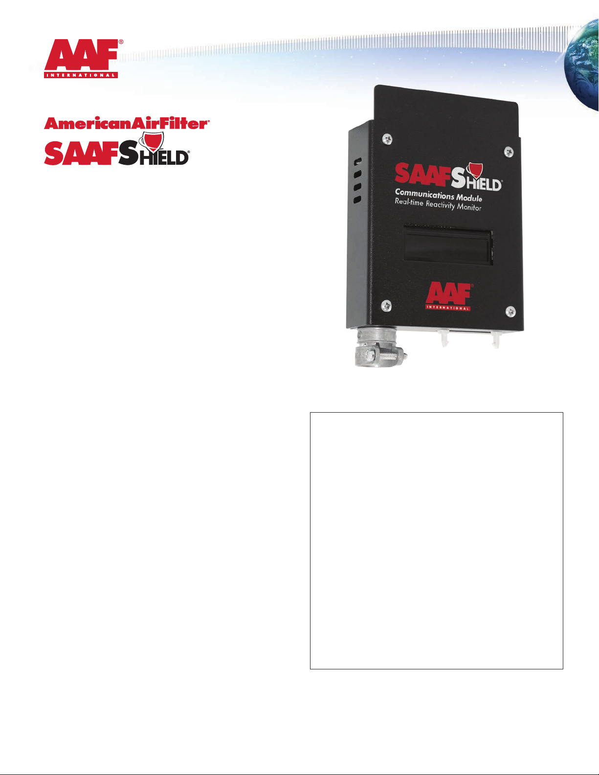
Communications Module
Real-time Reactivity Monitor
Installation, Operation, and
Maintenance Instructions
Read and Save These Instructions!
NOTE: 1. Read and understand all operating instructions before
using the SAAFShield Communications Module.
2. Save this manual for future reference.
This instruction manual provides important information on the
installation and operation of the AAF International SAAFShield
Communications Module. These instructions must be carefully
followed in order to operate the unit safely and correctly. If there are
any questions regarding the use or care of this unit, please contact
AAF at 888.AAF.2003 or by email at SAAFShield@aantl.com
for assistance.
Table of Contents
1.0 Principles of Operation
2.0 Components and Hardware
3.0 Placement of SAAFShield
4.0 Connecting to SAAFShield Detecting Unit
5.0 Connecting to 4-20 mA Output
6.0 Menu System
7.0 Programming Instructions
8.0 Data Input and Output
9.0 Local Readout
10.0 Troubleshooting
11.0 SAAFShield Parts List
1.0 Principles of Operation
The SAAFShield Communications Module in combination with the
Detecting Unit is part of the system that allows users to monitor
atmospheric corrosion in real time. This monitoring can be used to
display and trend corrosion data over time allowing users to
evaluate operational procedures, environmental factors, or other items
that occur at specic times and their impact on producing a corrosive
environment.The SAAFShield system utilizes Quartz Crystal
Microbalance (QCM) technology to measure metal corrosion due to
reactions with the environment.
Ribbon Connector
to SAAFShield® DU
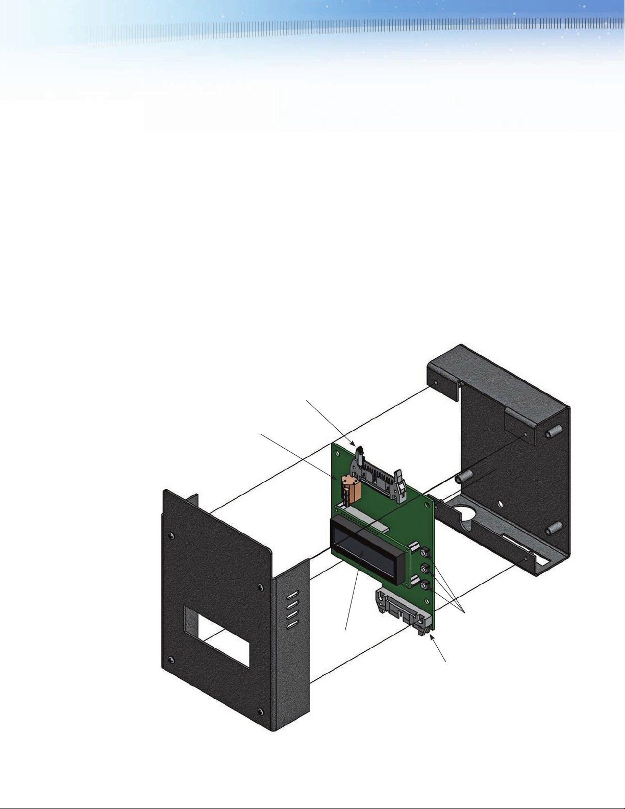
2.0 Components and Hardware
• Graphic LCD
• Integrated temperature sensor and humidity sensor
• 18-30 VDC power input
• Real time G-class and S-class monitoring
• Built in real time clock and calendar chip
• 4-20 mA output for Programmable Logic Controller (PLC) interfacing
• 3-inch ribbon cable
The SAAFShield Communications Module and its main components
are shown in Figure 1.
Further details on packaging and physical specications can be found
in the specication.
The Communications Module portion of the SAAFShield device is used
to read, compute, and transmit corrosion, temperature and relative
humidity data.
Connector for Power
and 4-20 mA Output
LCD Screen
Ribbon Connector
to SAAFShield
®
Menu Bottons (Up, Down, OK)
RU
Figure 1. Major components of the SAAFShield® Communications Module.
2
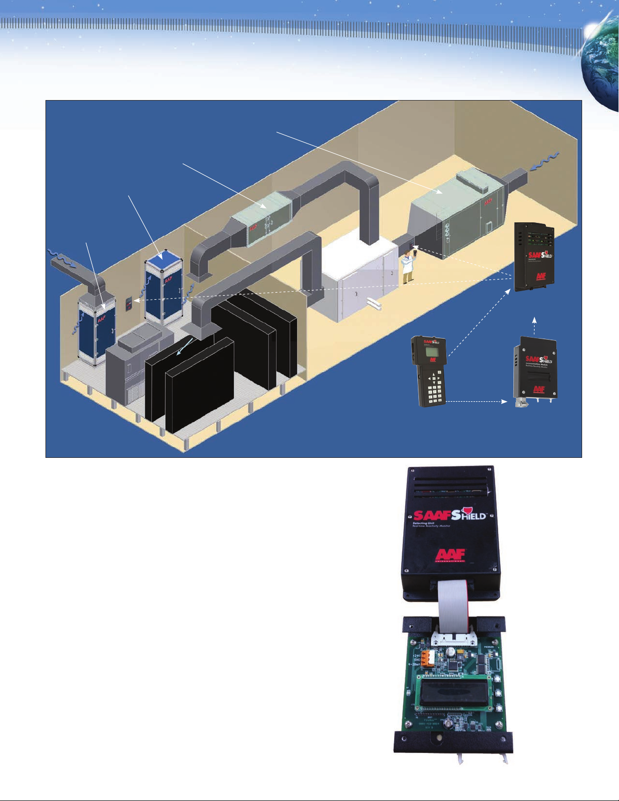
SAAF™
Recirculation Unit
SAAF™
Pressurization and
Recirculation Unit
SAAF™ Deep
Bed Scrubber
SAAF™ Side
Access Housing
SAAFShield® Detecting Unit
Computer Room Air
Conditioning Unit
(CRAC)
Figure 2. Typical placement for SAAFShield units.
3.0 Placement of SAAFShield Monitors
When determining the reactivity of a room or space within a building,
the SAAFShield should be placed in a location representative of the air
that contacts the electronics or materials being protected. If the
protected items are spread out within the space, then an approach,
similar to a thermostat should be used. If the protected items are
concentrated in one area inside the space, then a location as close as
possible to them is preferred.
When determining the condition downstream of a gas-phase lter or
scrubber to evaluate media performance and life, the SAAFShield
should be placed after the nal particulate lter. This will protect it from
the majority of particulates and allow it to monitor the condition of the
outlet air. When the rate of corrosion begins increasing beyond what is
normal, it is time to change the media or lter.
4.0 Connecting to SAAFShield Detecting Unit
The SAAFShield Detecting Unit and Communications Module come
equipped with 26-pin ribbon cable connectors. To connect the CM to
the DU, rst remove the CM cover and locate the ribbon cable connector at the top of the CM circuit board. (Figure 3)
Figure 3.
SAAFShield
Reading Unit
(for periodic data
®
SAAFShield®
Communications Module
(for continuous
data transmission)
3

5.0 Connecting to 4-20 mA Output
The unit connects to the host control/monitoring system via a standard
“3-wire” analog loop.
There are three terminals for this connection labeled as follows:
• +24V Positive 24 VDC
• GND 24 VDC common
• 4-20mA Signal to the analog input of the host system.
The 24 VDC power for the unit must be connected to the same source
as the host control/monitoring system, and in particular the 24 VDC
common (GND) must be the same as is used for reference by the
analog input module in the host control/monitoring system. (Figure 4)
6.0 Menu System
The SAAFShield Communications Module has three push buttons
to the right of the LCD display (Figure 5). Press any button to enter
the menu.
4-20 mA
Connector
Figure 4.
Detecting Unit Connector
Reading Unit Connector
Figure 5.
Up Button Down Button OK Button
1. The Communications Module will not enter the menu system if
data is being transmitted. Transmitting notice will be shown on
the LCD display.
2. Press any of the three buttons to enter the menu system. If the
unit is not transmitting data, you will enter the menu system
immediately. If the unit is transmitting data, you will enter the
menu system once the transmitting procedure is complete.
3. When the Communications Module is in the menu, the selected
eld will blink.
4. Use the UP and DOWN buttons to increase /decrease the setting
of that eld.
5. Use the OK button to select the value and scroll to the next eld.
6. If Exit (EXT) eld is reached using the OK button, press either
UP or DOWN to exit from menu system back into main mode.
7. After setting the time and date, it is recommended to initialize the
sensors. Once you leave the time/ date setup menu, the device
will ask if the sensors should be initialized. Press the UP button to
initialize the sensors or press DOWN to exit the menu system.
Note: The Communications Module will conduct the next data
transmission when the scheduled time comes though the LCD
display will NOT change to show this transmission. The red LED
on the left of the LCD display will blink at a faster rate when the
transmission is taking place.
7.0 Programming Instructions
When programming your building management software to receive
the 4-20 mA signal from the SAAFShield CM, you can utilize three
different languages: structured text, ladder logic, and function block
diagram. Please refer to AAF document SAAFShield Appendix
GPF-3-118, “Detailed Programming Instructions for SAAFShield
Communications Module.”
4

8.0 Data Input and Output
The SAAFShield Detecting Unit control logic interface block interprets
the 4-20 mA signal originating in the SAAFShield Communications
Module and produces a set of data consisting of each piece of data
collected by the SAAFShield detecting unit. The block also has some
failure detection capabilities. If a failure is detected the Fail bit is set
and a fail code is populated.
Block Diagram
FAL
In
Qui
SAAFShield
Communications
Rst
Module
Inputs
Parameter Name Type Description
In DINT Physical IO Tag
Qui Boolean Signal Quality
Rst Boolean Initialize output to starting values
Details
Parameter Name Type Description
FAL Boolean True if QUI is False
CumCu DINT Cumulative Copper reading in angstroms
CumAg DINT Cumulative Silver reading in angstroms
IncCu DINT Incremental Copper reading in angstroms
IncAg DINT Incremental Silver reading in angstroms
RH Real Relative Humidity reading
Temp Real Temperature reading
Error Real Error Code
Notes:
The range and unit of measure for all metal readings is 0 – 4000 angstroms.
• Relative Humidity is measured 0 – 100%.
• Temperature is measured -50 – 150º C
Pulse Codes
Variable Number Pulse Level Length
of Pulses (raw value) of Time
Start Signal 1 6.28 mA or 16486 3 seconds
Inter-data Pulse 2 8.58 mA or 22486 1 second each
Data Transfer 1 N/A 5 seconds
CumCu
CumAg
IncCu
IncAg
RH
Temp
Error
Cycle
Every 15 minutes the SAAFShield Communications Module sends data
to the analog input (SigIn). It sends the start signal for 3 seconds, waits
2 seconds, and then begins data transmission. Each measurement
is transmitted for 5 seconds. There is a two second wait followed by
two inter-data pulses. Then the next measurement sequence is
transmitted. The chart below (Figure 6) shows an example sequence.
Note that all data transmitted is set high. When the Communications
Module has sent all pieces of data, it waits for 15 minutes before
beginning the cycle.
Figure 6.
Steps
1. Send one 6.28 mA pulses of 3 seconds.
2. Wait 2 seconds.
3. Transmit Cumulative copper data in the range of 4-20mA
for 5 seconds.
4. Wait 2 seconds.
5. Send two 8.58 mA pulses of 1 second each with inter-pulse
pause of 1 second (set loop to 4mA during pause)
6. Wait 2 seconds.
7. Transmit Cumulative silver data in the range of 4-20mA
for 5 seconds.
8. Wait 2 seconds.
9. Send two 8.58 mA pulses of 1 second each with inter-pulse
pause of 1 second (set loop to 4mA during pause)
10. Wait 2 seconds.
11. Transmit incremental copper measurement in the range of 4-20mA
for 5 seconds.
12. Wait 2 seconds.
13. Send two 8.58 mA pulses of 1 second each with inter-pulse
pause of 1 second (set loop to 4mA during pause)
14. Wait 2 seconds.
15. Transmit incremental silver measurement in the range of 4-20mA
for 5 seconds.
16. Wait 2 seconds.
17. Send two 8.58 mA pulses of 1 second each with inter-pulse
pause of 1 second (set loop to 4mA during pause)
18. Wait 2 seconds.
5

19. Transmit Relative Humidity measurement in the range of 4-20mA
for 5 seconds.
20. Wait 2 seconds.
21. Send two 8.58 mA pulses of 1 second each with inter-pulse
pause of 1 second (set loop to 4mA during pause)
22. Wait 2 seconds.
23. Transmit Temperature measurement in the range of 4-20mA
for 5 seconds.
24. Wait 2 seconds.
25. Send two 8.58 mA pulses of 1 second each with inter-pulse
pause of 1 second (set loop to 4mA during pause)
26. Wait 2 seconds.
27. Transmit the fault data for 5 seconds.
6 to 8 mA: Power supply out of tolerance
8 to 10 mA: Copper out of range
10 to 12 mA: Silver out of range
12 to 14 mA: Gold out of range
14 to 16 mA: Self diagnostic failed, replace board
16 to 18 mA: Invalid time/date
18 to 20 mA: Other errors
9.0 Local Readout
The LCD on the front of the Communications Module has six (6)
screens.
3. Copper Corrosion Classication for the past 24 hours and the past
30 days
4. Silver Corrosion Classication for the past 24 hours and the past
30 days
1. The standard the device is currently congured to. The
Communications Module standard is set by the factory to the
standard of your choice. The choices in the standards are:
- Legacy Corrosion Control (ISA 71.04-1985)
- RoHS Corrosion Control (ASHRAE TC 9.9)
- or Museum & Archive
**Display charts of each standard, those on last page of SAAFShield brochure
GPF-1-140.
2. Temperature (ºC) and Relative Humidity (%)
6
5. Summary of the Environment’s Classication. This will report the
harshest of the classications for the standard used
6. Transmitting

10.0 Troubleshooting
Error Codes
When a detectable failure occurs, the fail bit is set and the failure code
is populated. The failure codes have the following meaning:
11.0 SAAFShield Parts List
It is recommended that the following spare parts be stored at the
installation site for replacement purposes. Consult with your AAF
representative to determine actual quantities required.
Code Number Meaning
0-5 mA No failure
6-8 mA Power Supply out of Tolerance
8-10 mA Copper out of Range
10-12 mA Silver out of Range
12-14 mA Gold out of Range
14-16 mA Self diagnostic, failed replace board
16-18 mA Invalid time/date
18-20 mA Other errors
Description Part Number
Detecting Unit (DU) 392-803-101
Silver Sensor 392-803-010
Gold Sensor 392-803-011
Copper Sensor 392-803-012
Reading Unit (RU) 392-803-001
Connection Cable (DU-RU) 392-803-003
12V Adaptor 392-803-000
Communications Module (CM)
- congured for Legacy 392-803-510
- congured for RoHS 392-803-520
- congured for Museum 392-803-530
Connection Cable (DU-CM) 392-803-004
To order replacement parts call: 1-800-AAF-2003.
7

Communications Module Real-time Reactivity Monitor
NOTES:
GPF-3-118 NOV ‘13
AAF International Building
9920 Corporate Campus Dr., Suite 2200
Louisville, Kentucky 40223-5000
Customer Service 888.223.2003
Fax 888.223.6500
www.aantl.com
AAF has a policy of continuous product research and
improvement and reserves the right to change
design and specications without notice.
ISO Certied Firm
The USGBC Member logo and LEED® are trademarks owned by
the U.S. Green Building Council and are used by permission.
© 2013 AAF International
 Loading...