

AAF International PRU User Manual
SAAFTMAir Purification Systems Recirculation Unit (RU)
and Pressurization and Recirculation Unit (PRU)
with SAAFTMCassette Gas-Phase Chemical Filters
Installation, Operation, and Maintenance Instructions
Better Air is Our Business
®
1.0 Introduction
1.1 About this Document
This document contains the information necessary to properly receive,
assemble, install, operate, and maintain the AAF Recirculation Unit
(RU) and Pressurization and Recirculation Unit (PRU) filter systems
and filters. The purchaser, installer, and operator of the filter system
MUST read and comply with this document in its entirety prior to
installation of the equipment and its operation. Failure to comply with
the requirements of this manual may void the product warranty.
CAUTION
These instructions are specific to the AAF Recirculation Unit (RU) and
Pressurization and Recirculation Unit (PRU) filter systems and filters.
All ancillary tasks including, but not limited to, electrical and mechanical
work, equipment handling, and safety procedures, must be performed
in accordance with industry accepted practice and all relevant local,
state, and federal government codes, laws, and policies.
Table of Contents
1.0 Introduction
1.1 About this Document
1.2 Packaging and Shipping, Receiving and Inspection,
Handling and Storage
1.3 Product Descriptions
1.4 Product Model Designations
1.5 Product Drawings
1.6 Assembly – General Comments
1.7 Related System Equipment
2.0 Principles of Operation
2.1 General
2.2 Recirculation System
2.3 Pressurization System
3.0 Installation Instructions
3.1 Space Requirements
3.2 Foundations, Supports, and Anchoring
3.3 Typical RU Housing Details
3.4 General Filter System Installation Procedure
3.5 Preparation for Filter Installation
3.6 Prefilter Installation
3.7 Gas-phase Chemical Filter Installation
3.8 After-filter Installation
3.9 High Efficiency Filter Installation
3.10 Latch RU Doors
3.11 Pressure Gauge
3.12 Fans
4.0 Start-up Instructions
5.0 Maintenance
5.1 Prefilter
5.2 After-filter
5.3 High Efficiency Final Filters
5.4 Gas-phase Filter Monitoring
5.5 Removal and Replacement of Particulate and Gas-phase
Chemical Filters
5.6 Disposal of Used Filters
5.7 Gas-phase Chemical Filter Cassette Face Sealing Gaskets
5.8 After-filter and High Efficiency Particulate Filter Sealing Gaskets
5.9 Access Door Sealing Gaskets
5.10 General System Maintenance
6.0 Troubleshooting
6.1 High Pressure Drop Reading Across the Filter System
6.2 Visible Discharge of Particulate
6.3 Odors and Smells
6.4 Vibration
7.0 Spare Parts List
8.0 Equipment Characteristics, Dimensions, Operating
Weights, and Shipping Weights
9.0 Technical Guidelines
9.1 Fan Selection and Sizing
NOTE
The AAF Recirculation Unit (RU) and Pressurization and Recirculation
Unit (PRU) filter systems and filters are similar in most respects. For
ease of reading, this manual will refer only to the Recirculation Unit
(RU). Unless specifically stated otherwise, all references to the
Recirculation Unit (RU) will apply equally to the Pressurization and
Recirculation Unit (PRU). A detailed description of both systems can
be found in section 2.0, Principles of Operation.
1.2 Packaging and Shipping, Receiving and Inspection, Handling
and Storage
1.2.1 Packaging and Shipping: Unless otherwise defined in the
purchase order and agreed by AAF, the RU filter housing and filters
are packaged for domestic transit and shipped FOB the AAF
factory. The method of shipment will be as specified in the
customer’s purchase order to AAF.
1.2.2 Receiving and Inspection: Obtain a copy of the purchase
order, the product drawing that was submitted by AAF in
association with the order, and a copy of the bill of lading, along
with any other shipping papers. Upon receipt of the equipment, or
any part thereof, these documents shall be used to ensure that the
correct product has been received.
For maximum protection, complete the following steps upon receipt
of the RU and filters:
– Inspect the shipment and all associated documentation. Notify
the carrier immediately if there is any visible damage to the
packaging or the equipment, or a discrepancy in the shipping
papers. If necessary, file an immediate claim with the carrier
against such damage or discrepancy.
– Confirm that the equipment received agrees with the contents
of the shipping papers.
– Confirm that the shipping documents agree with the purchase
order. Refer to the product drawing submitted for the order as
necessary.
– If it is determined that any equipment ordered on the purchase
order has not been delivered and is not accounted for in the
shipping papers, contact AAF International immediately by calling
1-800-477-1214. Reference the AAF control number which will
be listed on the shipping papers.
Each shipment may include:
- One or more individually packaged RUs.
- Packaged particulate filters.
- Packaged gas-phase chemical filter cassettes.
Note that the RU and the particulate and gas-phase filters may
ship from different locations and be received at different times.
1.2.3 Handling and Storage: Following receipt, inspection, and
acceptance of the equipment, and prior to installation, the RU and
the particulate and gas-phase filters shall be handled with great
care. The RU may ship mounted vertically or horizontally on a pallet
for protection during shipping and handling. It is recommended that
it remains on its pallet until it has been moved to its final installation
location. Only personnel experienced in rigging and handling
equipment shall be employed for this task. In most cases, the RU
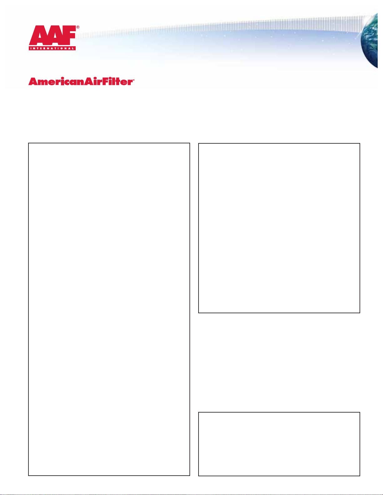
may be moved using a forklift. A suggestion for rigging horizontally
shipped equipment is shown in Figure 1. Rig the housing using
straps or a sling. Fasten the strapping under the skid on which the
RU ships. To prevent damage to the exterior surface of the RU, use
spreader bars at all times. Position the spreader bars to keep the
cables from rubbing against any part of the housing. Before
hoisting, make sure that the load is properly balanced.
! WARNING: The housing top (when shipped vertically) or the top-side
(when shipped horizontally) will not support the weight of the unit. Any
attempt to support the housing from these surfaces may result in serious
equipment damage and severe personal injury. Do not walk on the top or
the top-side of the unit, or use these surfaces for storage of materials.
The components shall be retained and stored in their protective
packaging until immediately prior to installation. Care shall be taken
to ensure that the packages are not dropped or subjected to any
impact loads.
At all times the equipment shall be protected from exposure to
weather. The equipment shall be stored in a clean, dry, temperature
controlled environment. All items shall be stored on pallets so that
they are elevated above grade. Recirculation Units (RU) shall not be
2
Figure 1
Spreader bar
RU
Straps
or
sling
Shipping skid
3
stacked. Particulate and gas-phase filters shall not be stacked more
than three (3) cartons high to prevent crushing. Only particulate filters
shall be stacked on particulate filters, and gas-phase filters on
gas-phase filters. The gas-phase filters ship inside a carton enclosed
in transparent protective plastic. Under no circumstances shall the
filters be removed from this plastic protection until immediately prior
to installation.
Filter products shall not be stored in areas where they may become
contaminated by chemicals, either acids or alkalis, in liquid, vapor, or
gaseous form.
1.3 Product Descriptions
1.3.1 Recirculation Unit (RU): Each RU will be received
individually mounted on a shipping pallet and wrapped in plastic for
protection during shipping. Refer to the product drawings submitted
on the order for details. The RU is typically supplied in one style,
the Type HD. This refers to style of SAAF Cassette gas-phase chemical
filter that can be accommodated in the unit (see 1.3.2 for details).
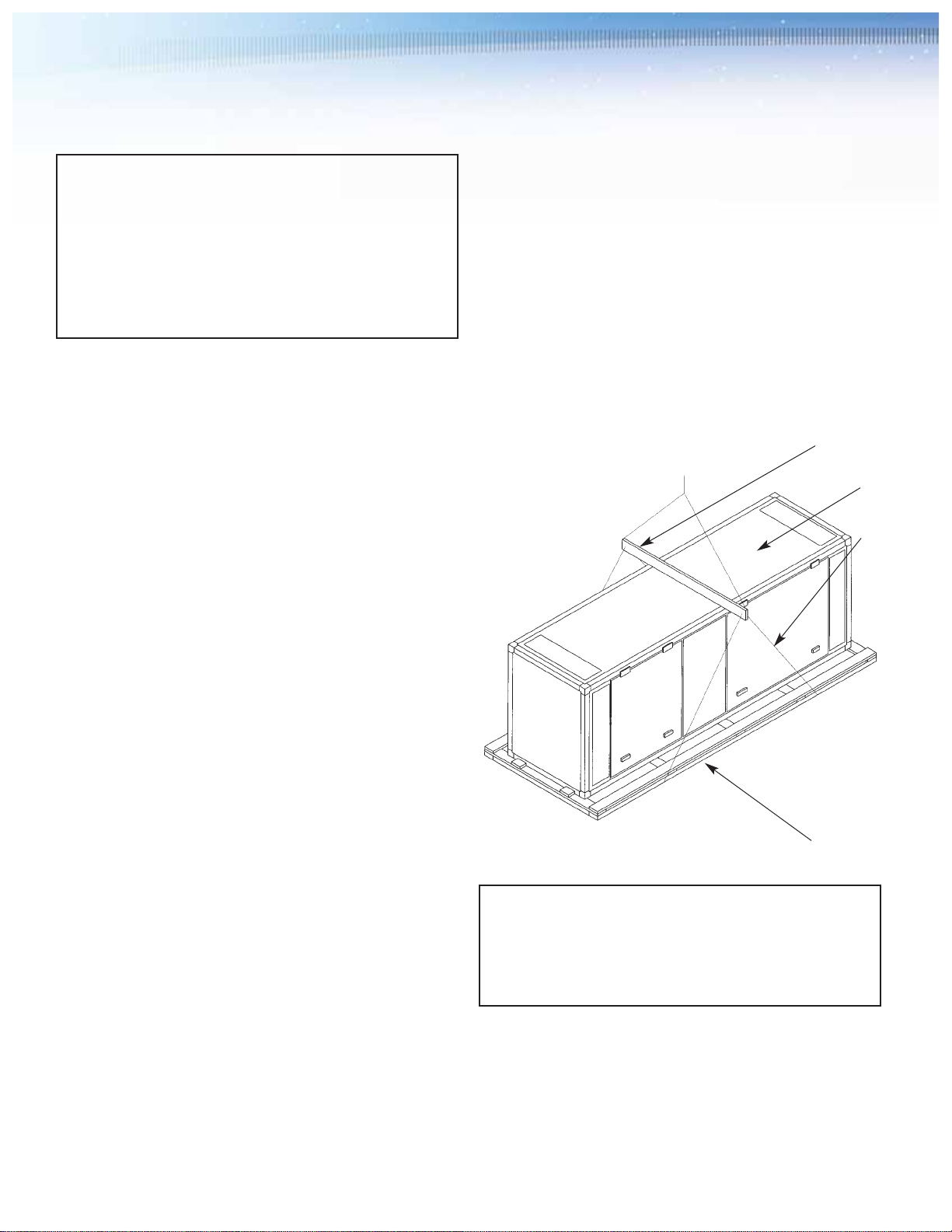
1.3.2 Gas-phase Chemical Filter Cassettes: Gas-phase filter
cassettes are shipped in cartons and plastic bags. The carton
shown below contains a single 6" high x 24" wide x 18" deep Type
MD cassette which is supplied as two (2) 6" high x 12" wide x 18"
deep half-cassettes. An HD cassette carton will contain a single 12"
high x 24" wide x 12" deep cassette which is supplied as two (2)
12 " wide x 12" deep half-cassettes.
Recirculation Unit, Model RU2000V with tracking to accommodate four (4) HD cassettes.
Typical Recirculation Unit.
* Substitute PRU for RU when the unit is a Pressurization and Recirculation Unit.
** In the case of the Pressurization and Recirculation Unit, the nominal delivered airflow is a combination of pressurization and recirculation airflow controlled via an in-built damper.
RU* - 500V – 2P – HD– F – HD – 2P – 6F
1.3.2 continued
12" high x 24" wide x 12" deep Type HD cassette ships in two halves.
The gas-phase chemical filter cassette typically supplied with the RU
is as follows:
1.3.3 Particulate Filters
Prefilters and After-filters - Particulate prefilters and after-filters will
typically be AAF PerfectPleat®pleated filters. Depending on the size
of the Recirculation Unit (RU) ordered, 24" high x 24" wide x 2" deep
full size filters or 12" high x 24" wide x 2" deep half size filters may be
supplied. PerfectPleat 2" deep filters are packaged 12 to a carton.
High Efficiency Filters – High efficiency filters will typically be AAF
M-Pak pleated filters. Depending on the size of the Recirculation Unit
(RU) ordered, 24" high x 24" wide x 6" deep full size filters or 12"
high x 24" wide x 6" deep half size filters may be supplied. M-Pak
filters are packaged two to a carton.
Note that other optional or special filter arrangements may be supplied,
depending on the requirements of the project. Check the purchase
order and the AAF submittal drawing(s) for details.
1.4 Product Model Designations
The product models are designated as shown in Table 1:
Table 1: Typical Model Numbers
Recirculation Unit (RU) Pressurization and Nominal Delivered Full Product Description
Recirculation Unit (PRU) Airflow (CFM) **
RU500V PRU500V 500 RU*-500V-2P-HD-F-HD-2P-6F
RU1000V PRU1000V 1000 RU*-1000V-2P-HD-F-HD-2P-6F
RU2000V PRU2000V 2000 RU*-2000V-2P-HD-F-HD-2P-6F
RU4000V PRU4000V 4000 RU*-4000V-2P-HD-F-HD-2P-6F
The full product description is defined below:
1.5 Product Drawings
Details of some standard RU filter systems are shown on the
following AAF drawings:
Model AAF Drawing Number
RU500V 114D-3025889
RU1000V 114D-3025855
RU2000V 114D-3025897
Copies of the appropriate drawings will have been supplied as part of
the AAF submittals in response to the purchase order. Obtain and
review the drawing(s) before proceeding with the installation of the filter
system. The RU filter system drawings include the following details:
– Overall filter system dimensions
– Shipping weights
– Operating weights
4
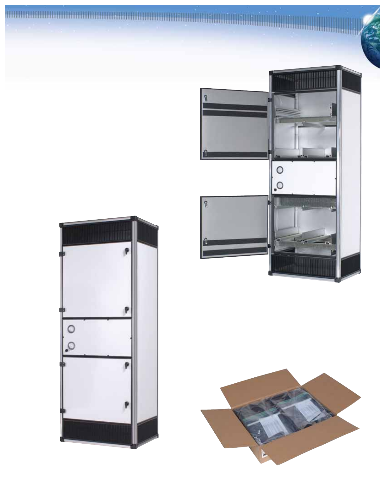
Supports a 6" deep particulate final filter
Supports a 2" deep particulate after-filter
Second gas-phase chemical filter bank, supports Type HD cassettes
Fan
First gas-phase chemical filter bank, supports Type HD cassettes
Supports a 2" deep particulate prefilter
Nominally rated to deliver 500 CFM in a vertical airflow orientation
Recirculation Unit (RU)

5
– Sizes and quantities of the particulate and gas-phase filters
required
– Details of the gas-phase chemical media supplied
– Details of the particulate filters supplied
– System design airflow
– Pressure losses across the filter system at nominal airflow design
velocities
– Product details
1.6 Assembly – General Comments
As indicated previously, the individual components that will comprise
the filter system will ship separately and will be required to be
installed on site. The RU is a self-contained product and,
consequently, a minimum amount of assembly is required. Refer to
section 3.0, Installation Instructions, of this manual for further detailed
instructions. Consult with an experienced installer to obtain an
accurate estimate of the time, personnel, and equipment resources
and tools that will be required to complete the assembly and
installation of the filter system. Site assembly will be limited to moving
and lifting individual components, screwing components together, and
caulking. The RU weights and dimensions can be found on the
product submittal drawings. The gas-phase chemical filters will
typically have a maximum weight of approximately 40 pounds (20kg).
Particulate filters will typically weigh less than the gas-phase filters.
Completion of the following preparations and provision of the following
items will be the responsibility of the installer or others:
– Site preparation
– Connecting screws and hardware for attaching inlet and outlet
ducts, if required.
– Provisions for anchoring and supporting the RU, including anchor
bolts, angles, straps, hangers and cradles, etc.
– Caulk, as required
– Inlet and outlet ducts, or other sheet metal parts, as required
These items will not be supplied by AAF unless noted specifically in
the AAF quotation and in the accepted customer purchase order.
NO WELDING WILL BE REQUIRED.
In general, assembly of the filter system will consist of the following:
– Preparation of the installation location
– Transportation of all components to the installation location
– Unpacking the RU
– Installing the RU
– Installing inlet and outlet ducts, if required
– Unpacking and preparation of the gas-phase chemical filter cassettes
– Installing gas-phase chemical filter cassettes
– Unpacking particulate filters
– Installing particulate filters
– Cleaning the site
– Start-up and commissioning of the filter system
1.7 Related System Equipment: Ventilation systems will often
include other equipment including but not limited to:
– Fan(s), if not supplied as part of the RU
– Dampers
– Weather louvers
– Air tempering equipment
– Analog instrumentation
– Electronic instrumentation and controls
Neither the interface of these items with the filter system supplied by
AAF, nor the installation, operation, and maintenance of these items is
covered in this manual. Whether these items are supplied by AAF or
by others, consult the documentation specific to these products for
appropriate instructions.
2.0 Principles of Operation
2.1 General: An understanding of the design and operating principle of
the RU with gas-phase chemical filters is useful for effective
installation, operation, and maintenance. Typically, the RU and PRU
systems are intended to remove gaseous contaminants from intake
and/or recirculated ventilation air. Examples of such contaminants may be
nuisance odors and smells that may cause domestic and neighborhood
discomfort and reduce workplace productivity, or harmful gases that may
cause damage to health, plant, and product in industrial applications.
The heart of the system is the AAF SAAF Cassette. This is a highimpact plastic frame that supports various types of dry, granular,
chemical media between perforated screens that allow air to move
through the filter. The SAAF Cassette is designed to support the
chemical media in a V-bank configuration of media beds that
maximizes the media exposed to the air stream, reduces the air
stream velocity through the media bed, maximizes energy efficiency,
and maximizes the removal of contaminants and the life of the product.
The method of contaminant removal is through a combination of the
physical property of adsorption and the chemical process of oxidation.
AAF offers a variety of impregnated and un-impregnated dry granular
media to handle a wide range of contamination problems. For more
information on AAF’s gas-phase air cleaning products contact your
AAF representative.
The AAF RU is one of the various framing and support systems
designed to support the SAAF Cassette in the air stream and to allow
easy installation, operation, and maintenance of the system.
6
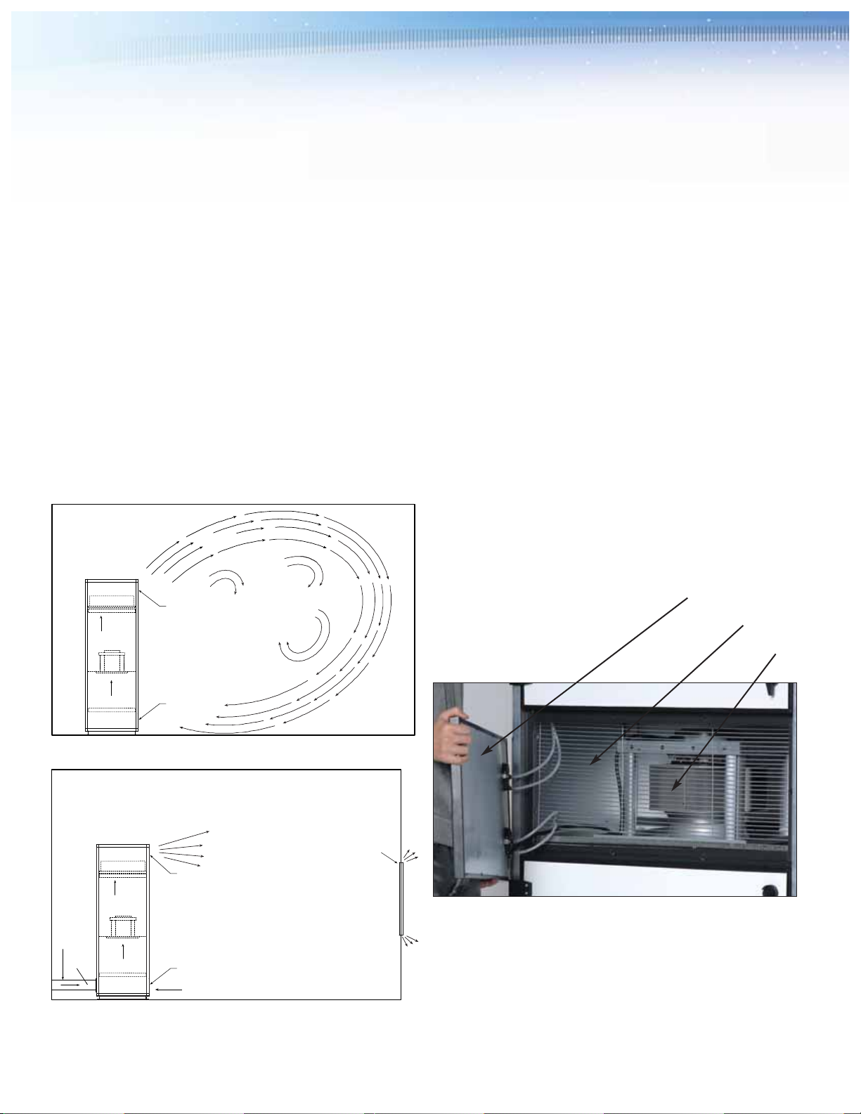
2.2 Recirculation System: The recirculation system is intended to
draw air from a defined space, clean the air, and then return the
cleaned air to the space. The system is supplied when contaminants
are generated within the space or infiltrate from outside the space. It is
normally provided to protect personnel, equipment (particularly
electronic equipment), or product. A typical schematic of the
recirculation system operation is shown in Figure 2.
2.3 Pressurization System: The pressurization system is intended to
pressurize a space by drawing air from outside the space, cleaning the
air, and then discharging the cleaned air to the space. The system is
supplied when contaminants are generated from outside the space. All
leakage will be from the higher pressure space within the room to the
lower pressure surrounding environment. This prevents outside
contaminants from entering the space. An optional arrangement allows
some in-room recirculation to take place. This system is normally
provided to protect personnel, equipment (particularly electronic
equipment), or product. A typical schematic of the pressurization system
operation is shown in Figure 3.
3.0 Installation Instructions
Consult the product drawing(s) submitted on this order before proceeding.
3.1 Space Requirements: A minimum of 36" clear space must be
available at the access side of the Recirculation Unit to perform
routine maintenance. Additional space may be required for inlet and
outlet ductwork.
3.2 Foundations, Supports, and Anchoring: The foundation and/or
supports must be designed to be adequate to support the filter system
operating weight, and any seismic, live or other loads (if any), with a
sufficient factor of safety as determined to comply with the
requirements of all applicable governing codes, standards, and laws.
Ensure that the foundation or support surface is level and smooth
before proceeding. The filter system is designed for operation in
indoor locations. The equipment is not specifically designed to resist
and operate under unusual dynamic loading situations such as
earthquake conditions. If the equipment is required to function in such
circumstances, special precautions may be required to ensure that the
equipment will remain intact, anchored, and functioning. If this
situation applies, consult with a qualified professional engineer before
installing the equipment.
RU
Filter
System
Fan
Outlet
Inlet
Contaminated
Air
Recirculated
Air
Clean Air
Enclosed Room
PRU
Filter
System
Fan
Outlet
Clean Air
*Pressurized Space
Air Leakage at
Windows, Doors and
Other Penetrations
will be Outwards
from the Room
Enclosed Room
Optional Inlet Damper and Dampered
In-room Inlet may be Supplied to
Allow some Recirculation of Air
Inlet Air
from Outside
of the Room
Duct
Figure 2 - Recirculation System Using the PRU
Figure 3 - Pressurization System Using the PRU
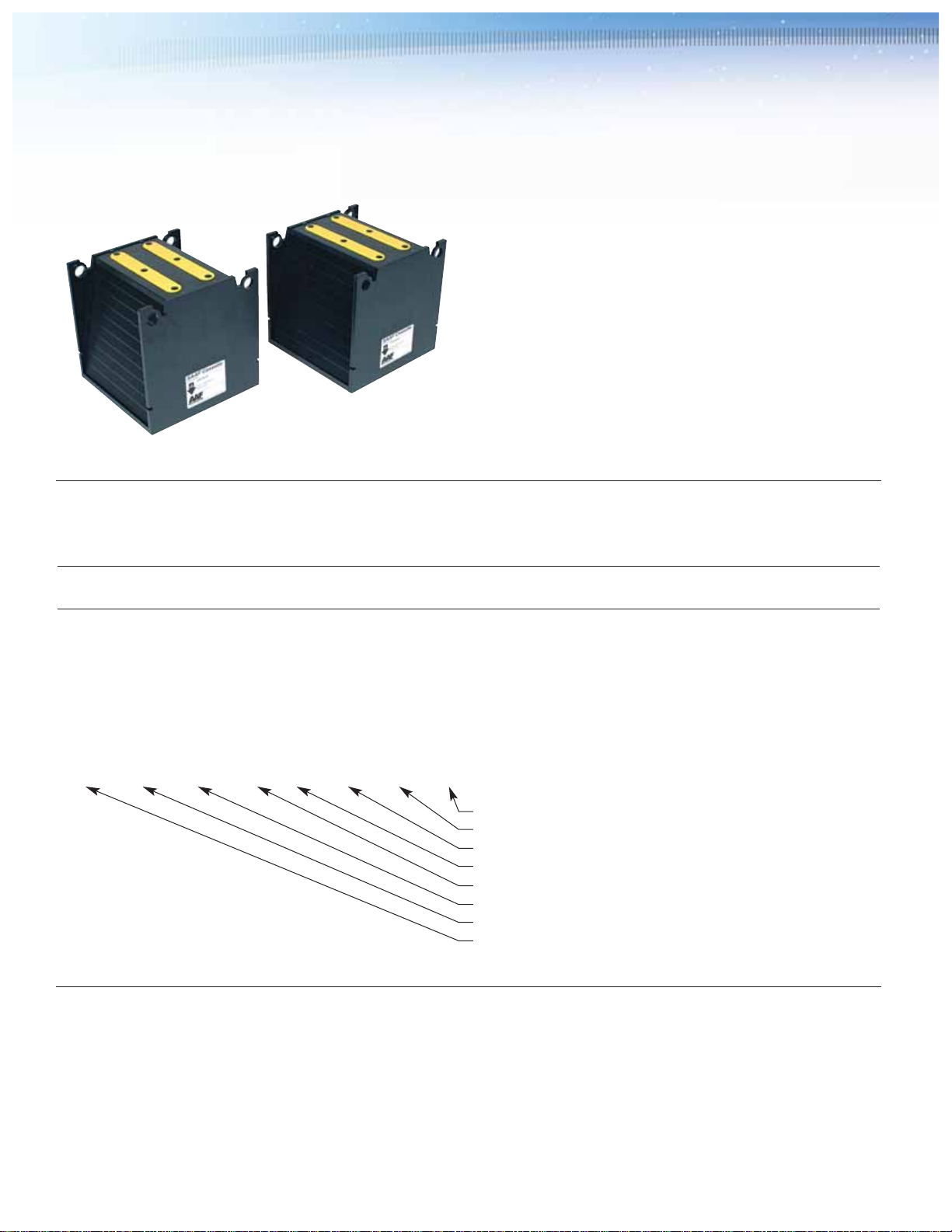
Fan section access panel
Safety grille
Fan
Typical fan section with access panel removed.
 Loading...