

AAF International Millennium User Manual
Better Air is Our Business
®
Millennium
®
Pulse-Jet Fabric Dust Collectors
I
nstallation, Operation, and Maintenance Instructions
Table of Contents
1.0 Introduction
1.1 About This Document
1.2 Shipping and Receiving
1.3 Assembly
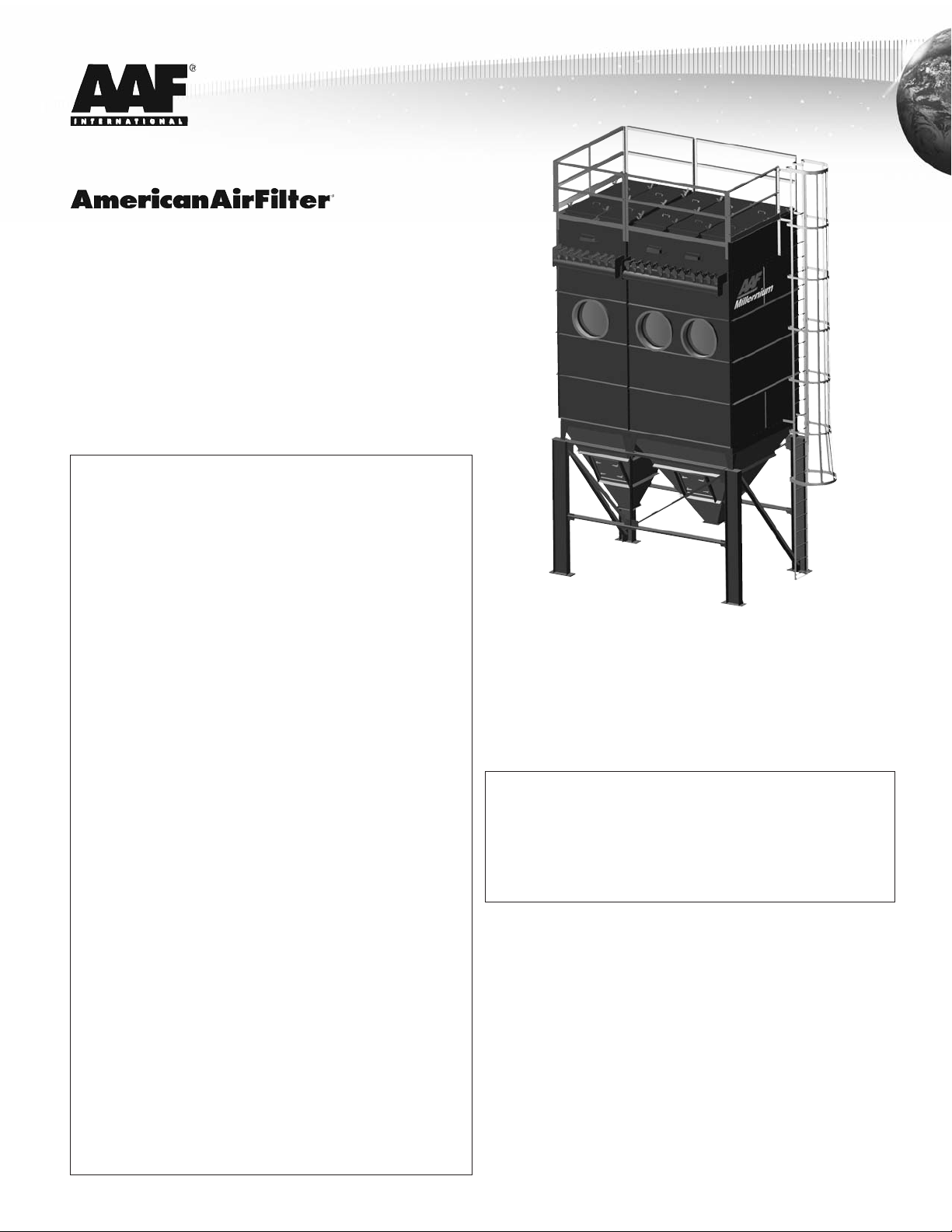
1.4 The Millennium - A Description
2.0 General Description
3.0 Installation Instructions
3.1 Space Requirements
3.2 Foundations and Anchoring
3.3 General Erection Procedure
3.4 Ductwork
3.5 Ladder and Handrail Assembly
3.6 Electrical Controls and Wiring
3.7 Compressed Air Connections
3.8 Bag, Cage and Venturi Assembly, and Pulse Pipe Installation
3.9 Roof Doors
3.10 Gauge Installation
3.11 Explosion Vent Installation
3.12 Hopper Discharge Device
4.0 Initial Startup Instructions
4.1 Preparation For Start Up
4.2 Timer Control
4.3 Pressure Demand Control
5.0 Principles of Operation
6.0 Maintenance
6.1 Daily
6.2 Monthly
6.3 Six Months
7.0 Troubleshooting
7.1 High Pressure Drop Reading
7.2 Visible Discharge
7.3 Insufficient Hood Control
7.4 Fabric Bag Problems
8.0 Spare Parts
9.0 Equipment Characteristics, Operating Weights,
and Shipping Weights
1.0 Introduction
1.1 About This Document
This document contains the information necessary to properly
receive, assemble, install, operate, and maintain the Millennium
dust collector. The purchaser, installer, and operator of the
Millennium MUST read this document in its entirety prior to
receipt and operation of the equipment.
CAUTION: These instructions are specific to the Millennium dust
collector. All ancillary tasks including, but not limited to, electrical and
mechanical work, equipment handling and safety procedures must be
performed in accordance with industry accepted practice and all
relevant local and federal codes.
1.2 Shipping and Receiving
The Millennium modules are packaged for domestic transit and
shipped FOB factory.
Obtain the original purchase order, the product drawing that was
submitted for the order, and a copy of the Bill of Lading along with
any other shipping papers. Upon receipt of the Millennium, these
documents should be used to ensure the correct modules/assemblies
have been received.
Complete the following steps upon receipt of the Millennium:
• Inspect the shipment and all associated documentation. Notify
the carrier immediately if there is any damage to the shipment,
or a discrepancy in the shipping papers.
• Confirm that the equipment received agrees with the
shipping documents.
• Confirm that the shipping documents agree with the Purchase
Order (P.O.). Refer to the product drawing submitted for the order,
as necessary.
• Confirm that the document package, consisting of a copy of the
IOM, the handrail, ladder, leg and brace installation drawings,
and the electrical connection diagram, has been received with
the shipment.
• If it is determined that modules/assemblies or any other equipment
specified on the P.O. has not been delivered, and is not accounted
for in the shipping documentation, contact AAF International
immediately at 800.477.1214.
The shipment will consist of assembled modules and some
loose parts for attachment at the jobsite, and will include the
following components:
1. Fully assembled plenum, housing and hopper modules.
2. Support structures including leg and bracing assemblies. See
drawings included with shipment for the proper number of parts.
3. Compressed air manifold connection kits for multiple modules.
4. One pulse control assembly for each unit.
5. Filter bags and cages. These filter elements may be shipped and
received separate from the other listed components.
6. Safety hand rails for standard plenum style units.
7. Safety ladder and cage assembly
8. Hardware kit
9. Caulk
1. Assemble Leg & Brace structure.
2. Seal with caulk and bolt together each adjoining module
(if multiple modules have been supplied).
3. Raise each module/assembly, and then attach and anchor to the
support legs and bracing structure.
4. Install the safety ladder.
5. Install the safety railing.
6. Install compressed air manifold interconnection kit(s) (if multiple
modules have been supplied).
7. Install compressed air manifold customer supplied
condensate drain(s).
8. Connect compressed air supply to the compressed air manifold.
9. Mount and wire the pulse control.
10.Attach inlet and outlet air ducts.
11.Install the filter elements.
12.Install optional components.
Detailed instructions regarding each of these operations are provided
in subsequent sections of this manual.
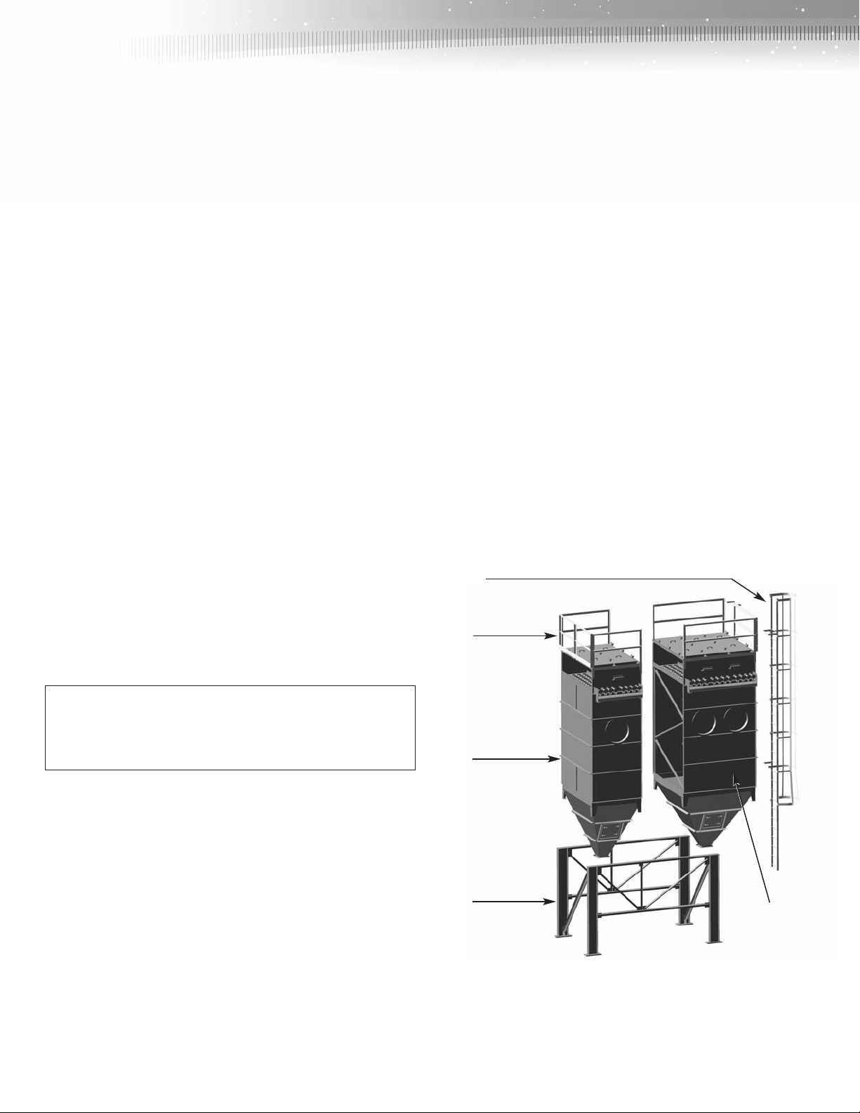
Access
Ladder
Safety
Railing
NOTE: Anchor bolts for bolting the equipment to the foundations and
hardware for connecting the inlet and outlet ducts are not included
with the Millennium and must be supplied by others.
Optional components such as hopper discharge devices, gauges and
other ancillary equipment may also be included in the shipment.
Consult the P.O. and shipping documents to confirm.
1.3 Assembly
The Millennium has been designed specifically to minimize the
amount of jobsite assembly required. Consult with an experienced
rigger for an accurate estimate of the time and equipment that will be
required. All jobsite assembly will be limited to bolting components
together. NO WELDING WILL BE REQUIRED. Following is an outline
of the assembly required for a standard Millennium. See Figure 1 for
details of the Millennium:
2
96 Bag
Module
Legs &
Bracing
Figure 1. Millennium Components
NOTE: The modules will normally be bolted together prior to
attaching the legs, handrailing, and ladder.
144 Bag
Module
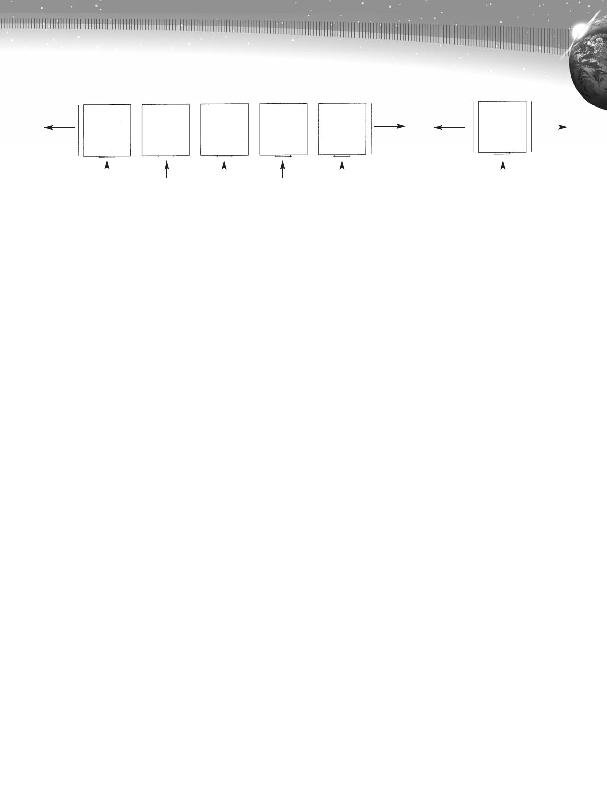
Std.
Outlet
Alt.
Outlet
A
B
B B C D
Std.
Outlet
Alt.
Outlet
Figure 2
Inlets Inlet
1.4 The Millennium - A Description
The standard Millennium collector comes in 14 basic sizes. The size
variations are composed of combinations of either 96 bag or 144 bag
modules, with one to five modules per unit. The Millennium will use
514" diameter bags in a 7" x 7" spacing pattern. Bag lengths of 8, 10,
12, and 14 ft. are available.
Standard module combinations are listed below. The 96 bag modules
are indicated as “96” and the 144 bag modules as “144”. The letter
designation refers to the diagram shown above in Figure 2.
Size Module Arrangement
96 D96
144 D144
192 A96 + C96
240 A96 + C144
288 A144 + C144
336 A96 + B96 + C144
384 A96 + B144 + C144
432 A144 + B144 + C144
480 A96 + B96 + B144 + C144
528 A96 + B144 + B144 + C144
576 A144 + B144 + B144 + C144
624 A96 + B96 + B144 + B144 + C144
672 A96 + B144 + B144 + B144 + C144
720 A144 + B144 + B144 + B144 + C144
There is no limit to the size collector that can be supplied.
However, any arrangements exceeding the combinations listed
above will require intermediate support legs and additional outlets
in order to maintain acceptable airflow velocities. See contract
drawings for details.
The modular design will permit an existing Millennium system to
be expanded with no significant disruption to the operating unit(s).
Housings, hoppers, plenums, and tube sheets are made of 10 ga.
carbon steel. Modules are available for -20" and -30" w.g. plenum
pressure, and for temperatures of 180, 270, and 400 degrees
Fahrenheit. Consult the P.O. and submittal documents to verify
which version you have.
Support legs are designed for 130 mph wind or Universal Building
Code seismic zone 4 loading, and are available for hopper clearances
of 4, 6, 8, and 10 ft. Up to five modules may be bolted together
and supported by one set of 4 legs. Standard design is for 4 ft.
hopper clearance.
The standard Millennium is supplied with a pyramid style hopper.
A trough style hopper is available as an option. Pyramid hoppers
have a minimum side slope of 60 degrees and a flanged outlet of
12" x 12" with a drilling that matches an optional Rotary Lock. The
trough hoppers have a 10" wide opening with drilled flanges for
conveyor mounting. Both types of hoppers have quick release lift-off
access doors.
The outlet plenum can be either open to roof top access or
walk-in style. Outlets may be located at either end of the plenum,
and have a 2'-1" x 8'-4" opening with a standard drilling as shown
on the drawings.
2.0 General Description
The Millennium is a modular, continuous, automatic, self-cleaning,
fabric pulse-jet dust collector. The standard module is an open top
design. Flanges inside the roof top doors prevent water from leaking
into the housing. The access doors are lift-off type. Each size 96
module has two doors; while the size 144 module has three doors.
The walk-in plenum design will have one 20” x 60” access door
opening at one end of the unit, opposite the air discharge opening.
Handrails and ladders are supplied with both plenum types. An
optional air and solenoid valve service platform is available. The
access ladder is selected to accommodate both bag length and
hopper clearance. On a standard roof top access unit, using a 12 ft.
bag with a 10 ft. hopper clearance, or a 14 ft. bag with either an 8 or
10 ft. hopper clearance, the access ladder is supplied in two sections
with an intermediate platform, to comply with OSHA regulations.
The cleaning cycle is controlled by a solid-state timer located in a
NEMA 4 enclosure. The timer control can be field adjusted for proper
operation. (See Bulletin E-97)
All modules are constructed with a 6" diameter surge tank
(compressed air manifold) which is fitted with 112" diaphragm pulse
valves. Pulse valves are connected to solenoid pilot valves with
plastic tubing on standard units, and with metal tubing on high
temperature units. See figure 3 for details of the compressed air surge
3
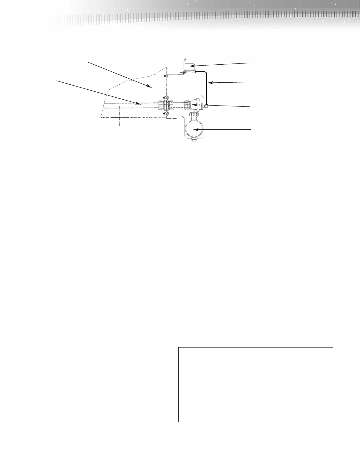
Clean Air
Plenum
Solenoid
Valve
Pulse Pipe
Figure 3
tank/pulse pipe assembly. Each pulse valve serves twelve bags.
1
Pulse pipes are 1
2", schedule 40 pipe and have a quick
disconnect coupling and a pinned end.
Standard collectors are primed and finish painted on the exterior with
high solids alkyd enamel. Interior surfaces have a prime coat. High
temperature collectors have one coat of zinc rich primer. Special paint
coatings are available as an option.
Some of the more common optional features available with the
Millennium include pressure demand cleaning, explosion vents, inlet
adapter plates, an arrangement to permit installation of up to 4"
thickness insulation at the destination job site, walk-in plenum, trough
hopper, high temperature features, and various ancillary components.
Consult the P.O. and submittal documents for what is included with
the specific order.
3.0 Installation Instructions
Consult the product drawing that was submitted for this order
before proceeding.
3.1 Space Requirements
A minimum of 24" clear space must be allowed on all sides of the
collector that do not include the access ladder or ductwork. The side
where the access ladder is located requires a minimum clear space of
46". For Walk-in Plenum units a minimum of 48” must be allowed on
the manifold side. More space may be required where inlet or outlet
ductwork and the explosion vent is located. For standard plenum top
access units, be sure to allow adequate height for removal of bags
and cages.
3.2 Foundations and Anchoring
The foundation must be designed to be adequate to support the
collector’s operating weight (see Section 9), seismic, wind and snow
loads (if any), collected dust, and any optional equipment, in
accordance with appropriate codes. Secure all anchor bolts to ensure
that the collector is firmly attached to the foundation. Base plates on
columns may require grouting after leveling. Multiple module units,
operating at elevated temperatures, may require expansion provisions
in the structural supports (see erection drawings for details).
Air Hose
Diaphragm Pulse Valve
Compressed Air Surge Tank
3.3 General Erection Procedure
1. Spreader bars must be used at all times when handling the
Millennium to prevent any possibility of damage. These shall be
connected to the lifting lugs provided on the Millennium for this
purpose. Only personnel experienced in rigging and handling
heavy equipment shall be employed to erect the Millennium.
Refer to proper drawings for specific lifting instructions for
module configuration.
2. All modules shall be separately positioned on the structure and
adjacent to one another in the order in which they will be joined
together. (See Section 1.4)
3. All joints between one of the end modules and adjacent modules
shall be prepared for connection to one another. This applies to all
perimeter and internal connecting flanges. Ensure the following:
• All flanges are flat and planar. Correct any bending, warping, or
denting that may have occurred when the modules were being
transported or handled.
• All flanges are clean and free from debris, contamination and
discontinuities of any kind, such as weld or paint splatter, mud,
rust, oil, or grease.
• All bolt holes are correctly aligned.
4. Caulk all connecting surfaces using the caulking compound
supplied. On standard units, this is a butyl caulk. Silicone caulk is
supplied on units rated to 400°F. See Figure 4 for the method of
applying caulk to a housing flange.
CAUTION: Particular caution must be exercised when sealing the
internal connection between the tube sheets in adjacent modules.
The tube sheet is the horizontal plate through which the filters are
inserted and which forms the barrier between the clean and dirty air
sides of the collector. The flange of the tube sheet between modules
is provided with a double row of bolt holes. Each row of holes shall
be caulked as shown in Figure 4. It is only necessary to apply caulk
to one face of each joint. Apply the caulk liberally to ensure an
effective seal.
4
 Loading...