

Page 1
Riser Board PER-1110
Quick
Installation
Guide
PER-1110 Rev A Quick Installation Guide
Part No. 2007111011 Printed in Taiwan August 2003
Page 2
Riser Board PER-1110
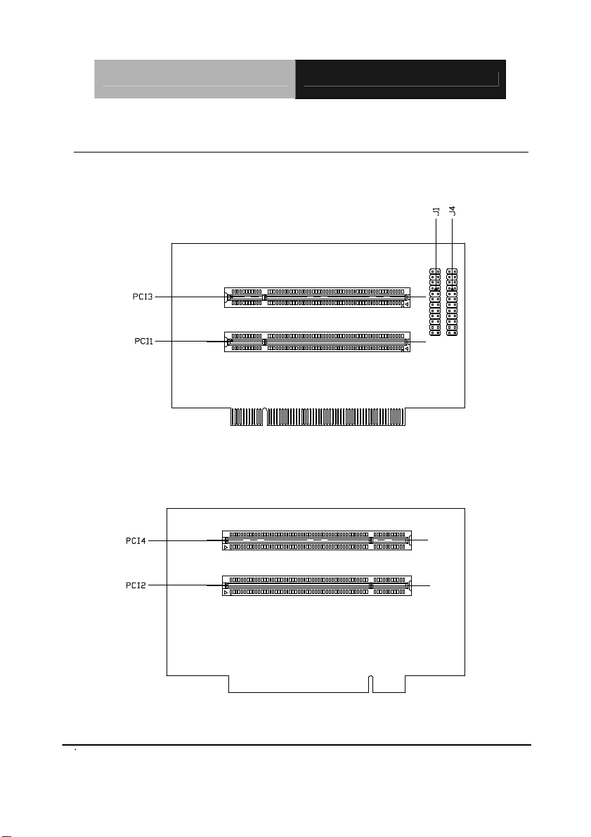
2.1 Location of Connectors and Jumpers
Locating connectors and jumpers (component side)
Locating connectors (solder side)
PER-1110 Rev A Quick Ins tallation Guide
1
Page 3

Riser Board PER-1110
2.2 Mechanical Drawing
Mechanical drawing (component side)
Mechanical Drawing (solder side)
PER-1110 Rev A Quick Ins tallation Guide
2
Page 4

Riser Board PER-1110
3
2.3 Setting Jumpers
You configure your card to match the needs of your
application by setting jumpers. A jumper is the simplest kind
of electric switch. It consists of two metal pins and a small
metal clip (often protected by a plastic cover) that slides over
the pins to connect them. To “close” a jumper you connect
the pins with the clip.
To “open” a jumper you remove the clip. Sometimes a
jumper will have three pins, labeled 1, 2 and 3. In this case
you would connect either pins 1 and 2 or 2 and 3.
2
1
Open Closed Closed 2-3
A pair of needle-nose pliers may be helpful when working
with jumpers.
If you have any doubts about the best hardware
configuration for your application, contact your local
distributor or sales representative before you make any
change.
Generally, you simply need a standard cable to make most
connections.
PER-1110 Rev A Quick Ins tallation Guide
3
Page 5

Riser Board PER-1110
2.4 Jumper setting
Modules J1 (PCI 1) / IDSEL J4 (PCI 3) / IDSEL
PCM-4896 11-12 / AD24 23-24 / AD30
PCM-4896L 11-12 / AD24 23-24 / AD30
PCM-5896C 23-24 / AD30 19-20 / AD28
PCM-6890B 15-16 / AD26 19-20 / AD28
PCM-6892 (Default) 19-20 / AD28 21-22 / AD29
PCM-6893 5-6 / AD21 21-22 / AD29
PCM-6894 21-22 / AD29 23-24 / AD30
PCM-6896B 15-16 / AD26 19-20 / AD28
PER-1110 Rev A Quick Ins tallation Guide
4
 Loading...