

Page 1

Copyright Notice
This document is copyrighted, 1998. All rights are reserved. The
original manufacturer reserves the right to make improvements to the
products described in this manual at any time without notice.
Acknowledgments
PCMCIA is a registered trademark of the Personal Computer Memory
Card Industry Association
CompactFlash is a registered trademark of SanDisk Corporation
For more information on PCMCIA and CompactFlash cards, please
contact the following organizations:
PCMCIA, 2635 North First St., Ste. 209, San Jose, CA 95131
Tel: 408-433-2273, Fax: 408-433-9558
http://www.pc-card.com
CompactFlash Association, PO Box 51537, Palo Alto, CA 94303
Tel: 650-843-1220 Fax: 650-493-1871
http://www.compactflash.org
Page 2
PCMCIA/CompactFlash™ ATA to IDE Drives and Modules
Table of Contents
Introduction .....................................................................................3
ATA PCMCIA drives ................................................................................3
ATA CompactFlash drives .......................................................................3
Product Overview ...........................................................................5
ATA to IDE Drives....................................................................................5
Common Specifications ......................................................................5
PCM-3116PC/F PCMCIA (ATA) to IDE Drive (front-mounted)................6
PCM-3116PC/R PCMCIA (ATA) to IDE Card (rear mounted)................. 6
PCM-3116 PC/104 PCMCIA and/or
CompactFlash (ATA) to IDE Modules......................................................8
Common Specifications ......................................................................8
PCM-3116 PC/104 PCMCIA/CompactFlash (ATA) to IDE Module ......... 9
PCM-3116PC PC/104 PCMCIA (ATA) to IDE Module ............................ 9
PCM-3116CF PC/104 CompactFlash (ATA) to IDE Module .................10
Hardware Installation....................................................................12
Jumper Settings..................................................................................... 12
PCM-3116PC/F PCMCIA (ATA) to IDE Drive (front-mounted)..............13
PCM-3116PC/R PCMCIA (ATA) to IDE card (rear- mounted) .............. 14
PCM-3116 Series PC/104 PCMCIA and/or
CompactFlash (ATA) to IDE Modules....................................................15
Using the PC/104 Connector ............................................................15
Using the IDE and Power Connector................................................15
BIOS Setup .................................................................................... 16
Drive Letter Assignments.......................................................................19
Pin Assignments ...........................................................................20
IDE Connector .................................................................................. 20
PC/104 Connector ............................................................................21
CompactFlash Connector................................................................. 22
PCMCIA Connector .......................................................................... 25
2
Page 3

User’s Manual
Introduction
Thank you for buying one of our PCMCIA or CompactFlash™ ATA to
IDE drives or modules.
ATA PCMCIA drives
ATA PCMCIA cards have long been used in notebook computers for
data storage and information sharing. PCMCIA drives are compact
and durable and provide an inexpensive way to add hard drive capacity
to a notebook computer. Our ATA to IDE drives allow a desktop
computer system to use PCMCIA ATA cards to facilitate information
sharing between notebook and desktop computer systems. In addition,
our ATA to IDE drives give system integrators the option of using
PCMCIA drives as an alternative to conventional floppy, hard disk and
CD-ROM disc drives. PCMCIA drives are particularly well-suited for
use in harsh industrial computing environments where heat, dust and
vibration prevents the use of other types of drives.
ATA CompactFlash drives
CompactFlash™ is the world's smallest removable mass storage
device. The technology was first introduced by SanDisk Corporation
in 1994. CompactFlash cards weigh only 14 grams and are approximately the size of a book of matches.
CompactFlash cards connect to readers and other devices through a 50pin connector, compared to the 68-pin connector that is used by
PCMCIA cards. However, CompactFlash cards fully comply to ATA
specifications.
3
Page 4

PCMCIA/CompactFlash™ ATA to IDE Drives and Modules
CompactFlash cards use nonvolatile flash technology and, like mechanical disk drives, can retain data without a battery or other electrical source. However, CompactFlash cards are much more durable than
mechanical disk drives and can withstand environments of substantial
vibration. CompactFlash devices provide reliable operation in a
temperature range of -25° C to +75° C compared with a range of +5° C
to +55° C for rotating drives.
CompactFlash technology is supported by all computing platforms and
operating systems that support the PCMCIA-ATA standard, including
DOS, Windows, OS/2, Apple System 7, most versions of UNIX, and
others.
The relatively low cost and low power consumption of CompactFlash
cards makes them particularly well-suited as a durable source of
storage for a wide range of industrial and consumer devices, including
portable computers, digital cameras, handheld data collection scanners,
cellular phones, PCS phones, PDAs, handy terminals, personal communicators, advanced two-way pagers, audio recorders, monitoring
devices and set-top boxes.
CompactFlash cards are available in 2, 4, 8, 10,15, 20 and 32 MB
capacities. At current market prices (mid-1998), CompactFlash cards
provide the most economical source of flash disk storage for capacities
greater than 4 MB.
4
Page 5

User’s Manual
Product Overview
There are five models in our product series. Three are ATA to IDE
drives, one is a CompactFlash to IDE drive and one is a combination
PC/104 PCMCIA/CompactFlash (ATA) to IDE Module.
ATA to IDE Drives
The ATA to IDE drives allow Type I/II/III ATA Flash and ATA HDD
PCMCIA cards to be accessed by a standard desktop computer. The
PCM-3116PC/F PCMCIA (ATA) to IDE drive and the
PCM-3116PC/R PCMCIA (ATA) to IDE card are very similar, with
the former being able to be mounted in a 3.5” disk drive bay while the
latter occupies an ISA slot for card access via the rear of the computer.
Common Specifications
• Complies with PCMCIA v. 2.1 / JEIDA 4.1 standards
• ATA to IDE interface
• 40-pin IDE connector
• 4-pin standard power connector
• Supports Type I/II/III ATA Flash, ATA HDD and CompactFlash
cards
• 5 V, 70 mA power consumption (typical)
• 0° C to 70° C operating temperature range
5
Page 6

PCMCIA/CompactFlash™ ATA to IDE Drives and Modules
PCM-3116PC/F PCMCIA (ATA) to IDE Drive (front-mounted)
The PCM-3116PC/F PCMCIA (ATA) to IDE drive is a PCMCIA
card drive that enables any PC compatible computer with an IDE
controller to read and write PCMCIA ATA Flash, ATA hard disk drive
and CompactFlash cards. It automatically converts the signal from the
68-pin PCMCIA connector to a 40-pin IDE connector thus allowing a
computer’s BIOS to access a PCMCIA card in the same manner as an
IDE drive. Operating system card and socket services are not needed
and the drive does not require the installation of a device driver.
The PCM-3116PC/F PCMCIA (ATA) to IDE drive is the same size as
a 3.5” floppy disk drive so it can be mounted in the front of a
computer’s case. This gives you convenient access to the drive.
Installation is easy - simply mount the drive in a free 3.5” drive mount
on the front of the computer, connect the IDE cable and then connect
the standard power cable from your computer’s power supply to the
power connector at the rear of the drive.
PCM-3116PC/R PCMCIA (ATA) to IDE Card (rear mounted)
The PCM-3116PC/R PCMCIA (ATA) to IDE card is a PCMCIA
card drive that enables any PC compatible computer with an IDE
controller to read and write PCMCIA ATA Flash, ATA hard disk drive
and CompactFlash cards. It automatically converts the signal from the
68-pin PCMCIA connector to a 40-pin IDE connector thus allowing a
computer’s BIOS to access a PCMCIA card in the same manner as an
IDE drive. Operating system card and socket services are not needed
and the drive does not require the installation of a device driver.
The PCM-3116PC/R PCMCIA (ATA) to IDE card is the same size as
a half-size ISA interface card. It installs into an ISA expansion slot of
your computer though the signal connections pass through an IDE
connector on the card. The PCM-3116PC/R is an excellent choice for
computer users who do not have a free 3.5” FDD bay on the front of
their computer chassis or for those who do not have to frequently
access the card. Installation is easy - simply mount the drive in a free
ISA slot on the rear of the computer, connect the IDE cable and then
connect the standard power cable from your computer’s power supply
to the power connector at the rear of the drive.
6
Page 7
User’s Manual
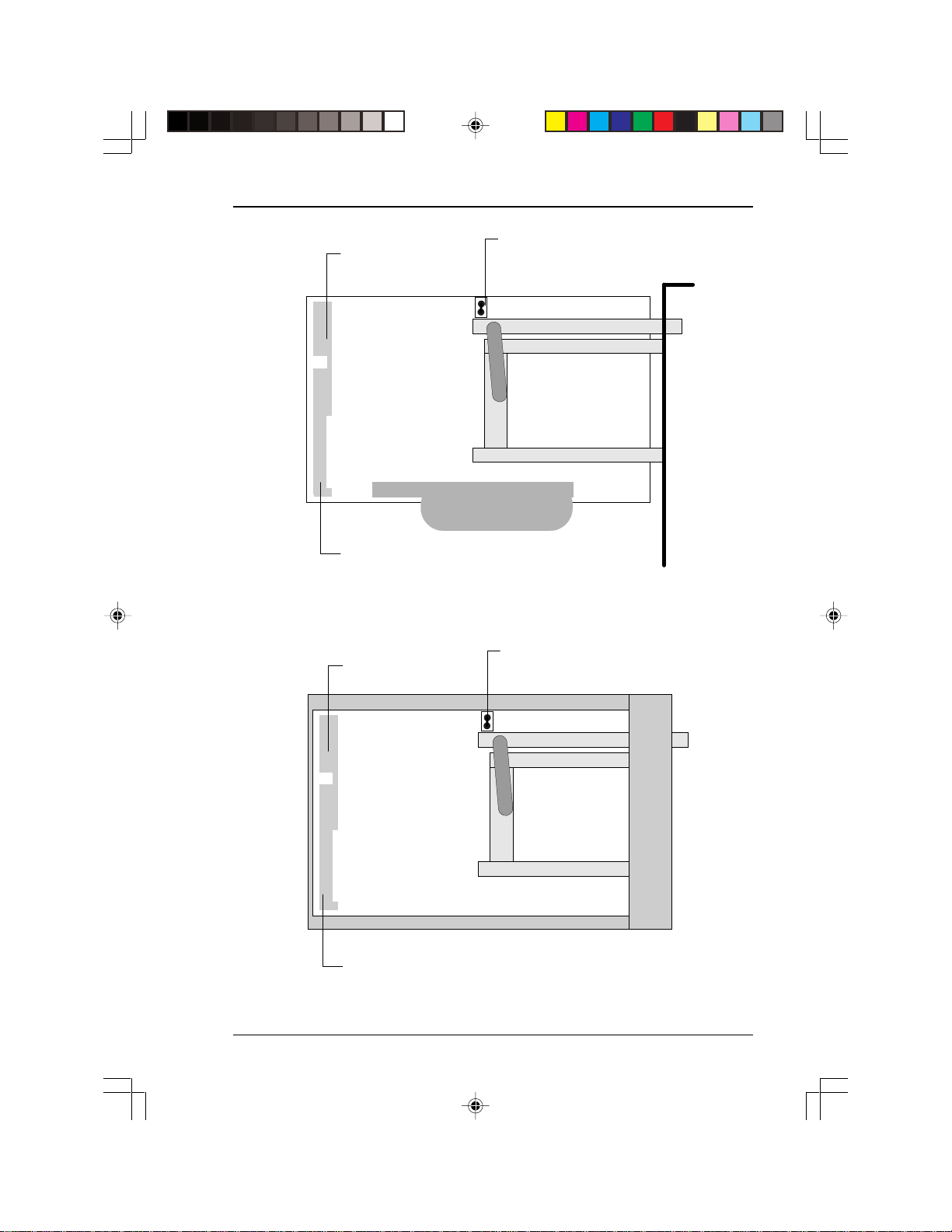
g
JP3
master slave settin
closed = master
40-pin IDE connector
open = slave
JP3
PCM-3116PC/F PCMCIA (ATA) to IDE drive
4-pin power
connector
PCM-3116PC/F PCMCIA (ATA) to IDE drive
JP3
master slave setting
closed = master
40-pin IDE connector
open = slave
JP3
PCM-3116PC/R PCMCIA (ATA) to IDE card
4-pin power
connector
PCM-3116PC/R PCMCIA (ATA) to IDE card
7
Page 8

PCMCIA/CompactFlash™ ATA to IDE Drives and Modules
PCM-3116 PC/104 PCMCIA and/or CompactFlash
(ATA) to IDE Modules
The PCM-3116 family of drives bring the covenience of PCMCIA and
CompactFlash cards to industrial computer systems. PC/104 is a
version of the standard PC bus designed specifically for the particular
challenges of using PC technology in industrial and embedded computer systems. All PCM-3116 models conform to the standard PC/104
form factor.
Connections can be made in two ways - either through the PC/104
connector or through the IDE and power connectors.
Common Specifications
• Complies with PCMCIA v. 2.1 / JEIDA 4.1 and CompactFlash
standards
• ATA/CompactFlash to IDE interface
• 40-pin IDE connector
• 4-pin standard power connector
• Supports Type I/II/III ATA Flash, ATA HDD and CompactFlash
cards through 68-pin PCMCIA connector or 50-pin
CompactFlash connector
• 5 V, 70 mA power consumption (typical)
• 0° C to 70° C operating temperature range
• Standard PC/104 form factor
8
Page 9
User’s Manual
PCM-3116 PC/104 PCMCIA/CompactFlash (ATA) to
IDE Module
The PCM-3116 is a PC/104 form-factor drive that allows computers
with an IDE controller to read and write both PCMCIA ATA Flash/
ATA hard disk cards and CompactFlash cards. The module converts
the 68-pin PCMCIA signal and the 50-pin CompactFlash signal to a
40-pin IDE signal. Your computer’s system BIOS will access the
PCMCIA and CompactFlash cards in the same manner as any other
IDE drive. Power is provided through a 4-pin compact power connector. The PCM-3116 does not require the installation of a device driver
and does not need to use the operating system’s card or socket services.
In order to provide additional flexibility to industrial computer system
integrators, the PCM-3116 also provides a PC/104 connector. This
allows it to be connected to other PC/104 modules or connected to
single board computers that feature a PC/104 connector. If the
PCM-3116 is connected using the PC/104 connector, there is no need
to connect cables to the IDE or power connectors because power and
communication is transmitted through the PC/104 connector.
PCM-3116PC PC/104 PCMCIA (ATA) to IDE Module
The PCM-3116PC is a PC/104 form-factor drive that allows computers
with an IDE controller to read and write PCMCIA ATA Flash and
ATA hard disk cards. The module converts the 68-pin PCMCIA signal
to a 40-pin IDE signal. Your computer’s system BIOS will access the
PCMCIA drive in the same manner as any other IDE drive. Power is
provided through a 4-pin compact power connector. The PCM3116PC does not require the installation of a device driver and does
not need to use the operating system’s card or socket services.
In order to provide additional flexibility to industrial computer system
integrators, the PCM-3116PC also provides a PC/104 connector. This
allows it to be connected to other PC/104 modules or connected to
single board computers that feature a PC/104 connector. If the
PCM-3116PC is connected using the PC/104 connector, there is no
need to connect cables to the IDE or power connectors because power
and communication is transmitted through the PC/104 connector.
9
Page 10

PCMCIA/CompactFlash™ ATA to IDE Drives and Modules
PCM-3116CF PC/104 CompactFlash (ATA) to IDE Module
The PCM-3116CF is a PC/104 form factor drive that allows computers
with an IDE controller to read and write CompactFlash cards. The
module converts the 50-pin CompactFlash signal to a 40-pin IDE
signal. Your computer’s system BIOS will access the CompactFlash
card in the same manner as any other IDE drive. Power is provided
through a 4-pin compact power connector. The PCM-3116CF does not
require the installation of a device driver and does not need to use the
operating system’s card or socket services.
In order to provide additional flexibility to industrial computer system
integrators, the PCM-3116CF also provides a PC/104 connector. This
allows it to be connected to other PC/104 modules or connected to
single board computers that feature a PC/104 connector. If the
PCM-3116CF is connected using the PC/104 connector, there is no
need to connect cables to the IDE or power connectors because power
and data communication is transmitted through the PC/104 connector.
10
Page 11

4-pin power
connector
40-pin IDE connector
User’s Manual
JP3
JP3 master slave setting
closed = master
open = slave
PC/104 connector
PCM-3116CF PC/104 CompactFlash (ATA) to IDE Module
4-pin power
connector
40-pin IDE connector
JP3
JP3 master slave setting
closed = master
open = slave
PC/104 connector
PCM-3116PC PC/104 PCMCIA (ATA) to IDE Module
11
Page 12

PCMCIA/CompactFlash™ ATA to IDE Drives and Modules
Hardware Installation
All of the PCMCIA/CompactFlash ATA to IDE drives and modules
can be installed into a computer within five minutes. The general
procedure is to mount the drive within your computer and connect
cables to enable power and data transfer to and from your device.
Jumper Settings
Before attempting to install your drive you may have to set jumpers on
the drive unit. Refer to the diagram on pages 7 and 11 for the location
of the jumper (JP3).
Most computer mainboards (and single-board computers) have two
IDE connectors. These two connectors are denoted the primary and
secondary IDE connectors. Each IDE connector can accommodate two
IDE devices provided that one is set as the master and one as the slave.
A single IDE connector cannot have two masters or two slaves.
If you are connecting your ATA to IDE drive to a IDE connector that
already has an IDE device (i.e., hard disk drive or CD-ROM disc
drive) connected to it, you must make sure that the jumper settings on
your ATA to IDE drive do not conflict with the existing device. For
example:
12
• If you are connecting your ATA to IDE drive to the same IDE
connector as the hard disk drive that your computer boots from,
you must set the hard disk drive as the master and the ATA to
IDE drive as the slave.
• If you are connecting your ATA to IDE drive to the same IDE
connector as your CD-ROM disc drive, set the ATA to IDE drive
as the opposite to your existing CD-ROM.
• If your ATA to IDE drive will contain the boot files for your
system, you must set it as the master.
Page 13

User’s Manual
Jumpers for hard disk drives and CD-ROM disc drives are normally
found on the end of the drive between the power and IDE connector.
Jumper settings for these devices can be found in the documentation
that came with the device or sometimes on labels on the device.
PCM-3116PC/F PCMCIA (ATA) to IDE Drive (front-mounted)
1 Turn off your computer.
2 Remove the case from your computer. Some computer cases
have a one piece design that requires the removal of screws on
the rear of your computer. ATX cases can be opened by first
removing the front plate and then unscrewing screws to remove
the side panels. If you require further information about your
computer, please consult your computer’s documentation.
3 Remove the protective faceplate that covers a free 3.5” disk
drive bay in your computer. The faceplate is held in place by two
plastic clips. Simply snap the faceplate out of its bracket.
4 Insert the PCM-3116PC/F PCMCIA (ATA) to IDE drive into the
computer’s 3.5” disk drive bay. Secure the drive by affixing four
screws to the bay’s rails.
5 Connect a 40-pin IDE cable from the ATA to IDE drive’s IDE
connector and then to the IDE connector on the mainboard.
Make sure that the cable’s red edge is connected to pin 1 on
each of the connectors.
6 Connect a power cable from your computer’s power supply to
the power connector on the ATA to IDE drive. Owing to the
shape of the cable and connector, it is impossible to plug in this
cable incorrectly.
7 Replace the case on your computer.
13
Page 14

PCMCIA/CompactFlash™ ATA to IDE Drives and Modules
PCM-3116PC/R PCMCIA (ATA) to IDE card (rear- mounted)
1 Turn off your computer.
2 Remove the case from your computer. Some computer cases
have a one piece design that requires the removal of screws on
the rear of your computer. ATX cases can be opened by first
removing the front plate and then unscrewing screws to remove
the side panels. If you require further information about your
computer, please consult your computer’s documentation.
3 Insert the PCM-3116PC/R PCMCIA (ATA) to IDE card into a free
ISA slot on your computer’s mainboard. Screw in a single screw
on the card’s backplate to secure the card firmly in the ISA slot.
4 Connect a 40-pin IDE cable from the ATA to IDE drive’s IDE
connector and then to the IDE connector on the mainboard.
Make sure that the cable’s red edge is connected to pin 1 on
each of the connectors.
5 Connect a power cable from your computer’s power supply to
the power connector on the ATA to IDE drive. Owing to the
shape of the cable and connector, it is impossible to plug in this
cable incorrectly.
14
6 Replace the case on your computer.
Page 15

User’s Manual
PCM-3116 Series PC/104 PCMCIA and/or
CompactFlash (ATA) to IDE Modules
There are two ways to connect the PCM-3116 series modules to your
computer - either through the PC/104 connector or through the power
and IDE connector.
Using the PC/104 Connector
If your computer has an on-board PC/104 connector, you can install
the PCM-3116 series module with one simple connection. Simply
insert the PC/104 connector pins on the bottom of the drive into a
standard PC/104 connector on your single board computer. This kind
of installation provides much flexibility for integrators of industrial
computer systems since additional PC/104 connectors can then be
installed on top of the PCM-3116 series module. Power and data
transfer is handled through the PC/104 connection. The connection of
several PC/104 connector to a single board computer enables the
integration of a multifunction, powerful computer that takes up very
little space. In addition, the PC/104 bus was designed specifically to
adapt the PC bus to the rigors of a harsh industrial environment that
includes vibration and dust.
Using the IDE and Power Connector
The PCM-3116 series modules can also be connected to a computer
using the conventional 40-pin IDE and 4-pin power connectors.
Connect an IDE cable from the drive’s IDE connector to the IDE
connector on your computer’s mainboard. This provides data transfer
between your computer and the drive. You must also connect a power
cable from your computer’s power supply to the drive.
15
Page 16

PCMCIA/CompactFlash™ ATA to IDE Drives and Modules
BIOS Setup
You must make changes to your system BIOS before you can use the
PCMCIA/CompactFlash (ATA) to IDE drive or module. This procedure is to enable your computer to work with the new drive. You will
be able to use the drive in the same manner as any other floppy disk,
hard drive or CD-ROM drive that is connected to your system after
making changes to your system’s BIOS.
The following procedure configures your new PCMCIA/CompactFlash
(ATA) to IDE drive or module. An example shows the installation of
the drive containing a 20 MB ATA Flash HDD PCMCIA card on a
computer that has an Award BIOS, ASUS mainboard and existing 4.3
GB HDD. Your own configuration will likely be different so the
screens will not be the same. However, the installation process is the
same for all ATA Flash, ATA HDD and CompactFlash cards. In
addition, BIOSes from other manufacturers may appear different.
Consult the documentation that came with your BIOS (likely included
in your mainboard manual) for specific information about your own
computer system.
16
1 Turn off your computer.
2 Connect the PCMCIA/CompactFlash (ATA) to IDE drive or
module to your computer as explained in the previous section.
3 Insert the PCMCIA or CompactFlash card into your drive unit.
4 Turn on your computer. You will immediately be given the option
to enter BIOS Setup before your operating system loads.
BIOSes manufactured by Award Software can be configured by
typing the Delete key. BIOSes from other manufacturers can be
entered by simultaneously typing Ctrl-Alt-S, Ctrl-Esc or Ctrl-F1.
Look at the on-screen message on your own computer for the
specific command.
5 The main BIOS Setup screen opens.
Page 17

ROM PCI/ISA BIOS (PI55T2P4)
CMOS SETUP UTILITY
AWARD SOFTWARE, INC.
User’s Manual
STANDARD CMOS SETTING
BIOS FEATURES SETUP
CHIPSET FEATURES SETUP
POWER MANAGEMENT SETUP
PNP/PCI CONFIGURATION
LOAD BIOS DEFAULTS
LOAD SETUP DEFAULTS
Esc: Quit
F10: Save & Exit Setup
SUPERVISOR PASSWORD
USER PASSWORD
IDE HDD AUTO DETECTION
SAVE & EXIT SETUP
EXIT WITHOUT SAVING
- ¯ ® ¬ - ¯ ® ¬
- ¯ ® ¬ : Select Item
- ¯ ® ¬ - ¯ ® ¬
(Shift)F2: Change Color
6 Choose the IDE HDD Auto Detect option. The IDE HDD Auto
Detect configuration screen opens.
ROM PCI/ISA BIOS (PI55T2P4)
CMOS SETUP UTILITY
AWARD SOFTWARE, INC.
HARD DISKSTYPE SIZE CYLS HEAD PRECOMP LANDZ SECTOR MODE
Primary Master 4310 14848 9 65535 14847 63 Normal
Primary Slave 0 0 0 0 0 Normal
Secondary Master 20 640 2 65535 639 32 Normal
Secondary Slave 0 0 0 0 0 0 0
Note: Some OSes (like SCO-UNIX) must use Normal for installation
Esc: Skip
7 Your BIOS will automatically identify the IDE HDD devices
(including ATA Flash, ATA HDD and CompactFlash cards) on
your computer and present options that allow you to select what
devices are connected to your computer.
8 When the IDE HDD auto-detection process is finished, you will
be returned to the main BIOS Setup screen. Choose the Standard CMOS Setup option to view the devices that will now be
able to be accessed by your computer.
17
Page 18

PCMCIA/CompactFlash™ ATA to IDE Drives and Modules
Date <mm:dd:yy> : Fri. Sep 18 1998
Time <hh:mm:ss> : 16 : 52 : 38
HARD DISKS TYPE SIZE CYLS HEAD PRECOMP LANDZ SECTOR MODE
Primary Master :Auto 4310 14848 9 65535 14847 63 Normal
Primary Slave :None 0 0 0 0 0 0 -------Secondary Master :A uto 20 640 2 65535 639 32 Normal
Secondary Slave :None 0 0 0 0 0 0 --------
Drive A: 1.44M. 3.5 in.
Drive B: None Base Memory: 640K
Video: EGA/VGA
Halt On: All But Keyboard Total Memory: 16384K
ESC: Quit -¯®¬: Select Item PU/PD/+/-: Modify
F1: Help <Shift> F2: Change Color
Extended Memory: 15360K
Other Memory: 384K
9 When finished, save your settting and exit the BIOS Setup. Your
computer will automatically re-boot. Allow your computer’s
operating system to load normally.
Open your File Manager or Windows Explorer to verify that your
operating system has identified the new drive correctly. The figure on
the following page shows that the new drive has been assigned a drive
letter according to the standard naming conventions of the operating
system.
Note: If your computer’s BIOS fails to identify the new drive
correctly, the problem is most likely due to one of two reasons.
First, check your drive’s jumper setting that controls whether
the drive is configured as either the master or the slave. If
changing the jumper setting does not correct the problem, it is
possible that the PCMCIA or CompactFlash card that you are
using is defective. Repeat BIOS configuration procedure with
a new card.
Warning: PCMCIA and CompactFlash cards in the
PCMCIA/CompactFlash (ATA) to IDE drive or
module are NOT hot-swappable. You must
turn off your computer before attempting to
eject or insert a card. Attempting to change
cards while the computer is running will not be
successful and may damage your card and/or
your computer.
18
Page 19

User’s Manual
Drive Letter Assignments
When you have finished installing your PCMCIA/CompactFlash
(ATA) to IDE drive or module in your computer and configured it
within the BIOS Setup, the drive can be used like any other drive on
your computer.
The following figure shows our computer after successful installation
of the drive. The computer originally had one hard drive with three
partitions. Before installation the drive partitions were assigned the
letters C, D and E. The drive letter assingnments are now the following:
• C: HDD (first partition)
• D: PCMCIA/CompactFlash (ATA) to IDE drive or module
• E: HDD (second partition)
• F: HDD (third partition)
19
Page 20

PCMCIA/CompactFlash™ ATA to IDE Drives and Modules
Pin Assignments
Power Connector
Pin Signal
1+5 V
2 GND
3 GND
4+12V
IDE Connector
Pin Signal Pin Signal
1 IDE RESET* 2 GND
3 DATA 7 4 DATA 8
5 DATA 6 6 DATA 9
7 DATA 5 8 DATA 10
9 DATA 4 10 DATA 11
11 DATA 3 12 DATA 12
13 DATA 2 14 DATA 13
15 DATA 1 16 DATA 14
17 DATA 0 18 DATA 15
19 SIGNAL GND 20 N/C
21 N/C 22 GND
23 IO WRITE 24 GND
25 IO READ 26 GND
27 IO CHANNEL READY 28 N/C
29 HDACKO* 30 GND
31 IRQ14 32 IOCS16
33 ADDR 1 34 N/C
35 ADDR 0 36 ADDR 2
37 HARD DISK SELECT 0* 38 HARD DISK SELECT 1*
39 IDE ACTIVE* 40 GND
20
Page 21

User’s Manual
PC/104 Connector
Pin Connector J1 Connector J2
Number Row A Row B Row C Row D
0 — — GND GND
1 IOCK# GND SBHE# MEM16
2 SD7 RESETDRV LA23 IO16#
3 SD6 +5V LA22 IRQ10
4 SD5 IRQ9 LA21 IRQ11
5 SD4 -5V LA20 IRQ12
6 SD3 DRQ2 LA19 IRQ15
7 SD2 -12V LA18 IRQ14
8 SD1 OWS# LA17 DACK0#
9 SD0 +12V MEMR# DRQ0
10 IOCHRDY GND MEMW# DACK5#
11 AEN SMEMW# SD8 DRQ5
12 SA19 SMEMR# SD9 DACK6#
13 SA18 IOW# SD10 DRQ6
14 SA17 IOR# SD11 DACK7#
15 SA16 DACK3# SD12 DRQ7
16 SA15 DRQ3 SD13 +5V
17 SA14 DACK1# SD14 MASTER#
18 SA13 DRQ1 SD15 GND
19 SA12 REFRESH# — GND
20 SA11 ATCLK# — —
21 SA10 IRQ7 — —
22 SA9 IRQ6 — —
23 SA8 IRQ5 — —
24 SA7 IRQ4 — —
25 SA6 IRQ3 — —
26 SA5 DACK2# — —
27 SA4 T/C — —
28 SA3 BALE — —
29 SA2 +5V — —
30 SA1 OSC — —
31 SA0 GND — —
32 GND GND — —
21
Page 22

PCMCIA/CompactFlash™ ATA to IDE Drives and Modules
CompactFlash Connector
niP
muN
1DNGdnuorG621DC-OdnuorG
230DO/I3ZO,Z1I7211D
340DO/I3ZO,Z1I8221D
450DO/I3ZO,Z1I9231D
560DO/I3ZO,Z1I0341D
670DO/I3ZO,Z1I1351D
70 I U3I232EC801AIZ1I331SV-OdnuorG
9EO-IU3I43DROI-IU3I
0190AIZ1I53RWOI-IU3I
1180AIZ1I63EW-IU3I
2170AIZ1I73YSB/YDRO1TO
31CCVrewoP83CCVrewoP
4160AIZ1I93LESC-IZ2I
5150AIZ1I042SV-ONEPO
6140AIZ1I14TESERIZ2I
7130AIZ1I24TIAW-O1TO
8120AIZ1I34KCAPNI-O1TO
9110AIZ1I44GER-IU3I
0200AIZ1I542DVBO/I1TO,U1I
1200DO/I3ZO,Z1I641DVBO/I1TO,U1I
2210DO/I3ZO,Z1I7480DO/I3ZO,Z1I
3220DO/I3ZO,Z1I8490DO/I3ZO,Z1I
42PWO 3TO9401DO/I3ZO,Z1I
522DC-O dnuorG05DNGdnuorG
langiS
emaN
epyTniP
tuOnI
epyT
niP
muN
langiS
emaN
1
1
1
1
1
1
O/I3ZO,Z1I
O/I3ZO,Z1I
O/I3ZO,Z1I
O/I3ZO,Z1I
O/I3ZO,Z1I
IU3I
edoMyromeMdraCCP:stnemngissAniPhsalFtcapmoC
epyTniP
tuOnI
epyT
1 These signals are required only for 16-bit access and not required when
installed in 8-bit systems. Devices should allow for 3-state signals not to
consume current.
2 Devices should be grounded by the host.
3 Should be tied to VCC by the host.
22
Page 23

User’s Manual
edoMO/IdraCCP:stnemngissAniPhsalFtcapmoC
niP
muN
1DNGdnuorG621DC-OdnuorG
230DO/I3ZO,Z1I7211D
340DO/I3ZO,Z1I8221D
450DO/I3ZO,Z1I9231D
560DO/I3ZO,Z1I0341D
670DO/I3ZO,Z1I1351D
71EC-IU3I232EC801AIZ1I331SV-OdnuorG
9EO-IU3I43DROI-IU3I
0190AIZ1I53RWOI-IU3I
1180AIZ1I63EW-IU3I
2170AIZ1I73QERIO1TO
31CCVrewoP83CCVrewoP
4160AIZ1I93LESC-IZ2I
5150AIZ1I042SV-ONEPO
6140AIZ1I14TESERIZ2I
7130AIZ1I24TIAW-O1TO
8120AIZ1I34KCAPNI-O1TO
9110AIZ1I44GER-IU3I
0200AIZ1I54RKPS-O/I1TO,U1I
1200DO/I3ZO,Z1I64GHCSTS-O/I1TO,U1I
2210DO/I3ZO,Z1I7480DO/I3ZO,Z1I
3220DO/I3ZO,Z1I8490DO/I3ZO,Z1I
4261SIOI-O3TO9401DO/I3ZO,Z1I
522DC-O dnuorG05DNGdnuorG
langiS
emaN
epyTniP
tuO,nI
epyT
niP
muN
langiS
emaN
1
1
1
1
1
1
epyTniP
O/I3ZO,Z1I
O/I3ZO,Z1I
O/I3ZO,Z1I
O/I3ZO,Z1I
O/I3ZO,Z1I
IU3I
tuOnI
epyT
1 These signals are required only for 16-bit access and not required when
installed in 8-bit systems. Devices should allow for 3-state signals not to
consume current.
2 Devices should be grounded by the host.
3 Should be tied to VCC by the host.
23
Page 24

PCMCIA/CompactFlash™ ATA to IDE Drives and Modules
niP
muN
1DNGdnuorG621DC-OdnuorG
230DO/I3ZO,Z1I7211D
340DO/I3ZO,Z1I8221D
450DO/I3ZO,Z1I9231D
560DO/I3ZO,Z1I0341D
670DO/I3ZO,Z1I1351D
70SC-IZ3I231SC801A
9LESATA-IU3I43DROI-IZ3I
0190A
1180A
2170A
31CCVrewoP83CCVrewoP
4160A
5150A
6140A
7130A
8120AIZ1I34KCAPNI-O1ZO
9110AIZ1I44GER-
0200AIZ1I54PSAD-O/I1NO,U1I
1200DO/I3ZO,Z1I64GAIDP-O/I1NO,U1I
2210DO/I3ZO,Z1I7480D
3220DO/I3ZO,Z1I8490D
4261SCOI-O3NO9401D
522DC-O dnuorG05DNGdnuorG
langiS
emaN
2
2
2
2
2
2
2
2
epyTniP
IZ1I331SV-OdnuorG
IZ1I53RWOI-IZ3I
IZ1I63EWIZ1I73QRTNIO1ZO
IZ1I93LESC-IU2I
IZ1I042SV-ONEPO
IZ1I14TESER-IZ2I
IZ1I24YDROIO1NO
tuO,nI
epyT
niP
muN
langiS
emaN
1
1
1
1
1
1
3
3
1
1
1
O/I3ZO,Z1I
O/I3ZO,Z1I
O/I3ZO,Z1I
O/I3ZO,Z1I
O/I3ZO,Z1I
I3ZO,Z1I
IU3I
IU3I
O/I3ZO,Z1I
O/I3ZO,Z1I
O/I3ZO,Z1I
edoMEDIeurT:stnemngissAniPhsalFtcapmoC
epyTniP
tuOnI
epyT
1 These signals are required only for 16-bit access and not required when
installed in 8-bit systems. Devices should allow for 3-state signals not to
consume current.
2 Devices should be grounded by the host.
3 Should be tied to VCC by the host.
24
Page 25

User’s Manual
PCMCIA Connector
:epyTdnastnemngissAniPAICMCPedoMyromeMdraCCP
muNniP
1DNGdnuorG53DNGdnuorG
23ODO/I3ZO,Z1I631DC-OdnuorG
340DO/I3ZO,Z1I7311D
450DO/I3ZO,Z1I8321D
560DO/I3ZO,Z1I9331D
670DO/I3ZO,Z1I0441D
71EC-IU3I1451D
801AIZ1I242EC9EO-IU3I341SV-OdnuorG
0144DRO-IU3I
119OAIZ1I54RWOI-IU3I
218OAIZ1I64
3174
4184
51EW-IU3I94
61YSB/YDRO1TO05
71CCVrewoP15CCVrewoP
81PPV)desuton(25PPV)desuton(
9135
0245
1255
227OAIZ1I65LESC-IZ2I
326OAIZ1I752SV-ONEPO
425OAIZ1I85TESERIZ2I
524OAIZ1I95TIAW-O1TO
623OAIZ1I06KCAPNI-O1TO
722OAIZ1I16GER-IU3I
821OAIZ1I262DVBO/I1TO,U1I
92OOAIZ1I361DVBO/I1TO,U1I
03OODO/I3ZO,Z1I468OD
131ODO/I3ZO,Z1I569OD
232ODO/I3ZO,Z1I6601D
33PWO 3TO762DC-OdnuorG
43DNGdnuorG86DNGdnuorG
langiS
emaN
epyTniP
tuO,nI
epyT
muNniP
langiS
emaN
1
1
1
1
1
1
1
1
1
epyTniP
O/I3ZO,Z1I
O/I3ZO,Z1I
O/I3ZO,Z1I
O/I3ZO,Z1I
O/I3ZO,Z1I
IU3I
O/I3ZO,Z1I
O/I3ZO,Z1I
O/I3ZO,Z1I
tuOnI
epyT
1 These signals are required only for 16-bit access and are not required
when installed in 8-bit systems. Devices should allow for 3-state signals
not to consume current.
2 Should be grounded by the host.
3 Should be tied to VCC by the host.
25
Page 26

PCMCIA/CompactFlash™ ATA to IDE Drives and Modules
:epyTdnastnemngissAniPAICMCPedoMO/IdraCCP
muNniP
langiS
emaN
epyTniP
1DNGdnuorG53DNGdnuorG
23ODO/I3ZO,Z1I631DC-OdnuorG
340DO/I3ZO,Z1I7311D
450DO/I3ZO,Z1I8321D
560DO/I3ZO,Z1I9331D
670DO/I3ZO,Z1I0441D
71EC-IU3I1451D
801AIZ1I242EC9EO-IU3I341SV-OdnuorG
0144DRO-IU3I
119OAIZ1I54RWOI-IU3I
216OAIZ1I64
3174
4184
51EW-IU3I94
61QERIO1TO05
71CCVrewoP15CCVrewoP
81PPV)desuton(25PPV)desuton(
9135
0245
1255
227OAIZ1I65LESC-IZ2I
326OAIZ1I752SV-ONEPO
425OAIZ1I85TESERIZ2I
524OAIZ1I95TIAW-O1TO
623OAIZ1I06KCAPNI-O1TO
722OAIZ1I16GER-IU3I
821OAIZ1I26RKPS-O/I1TO,U1I
92OOAIZ1I36GHCSTS-O/I1TO,U1I
03OODO/I3ZO,Z1I468OD
131ODO/I3ZO,Z1I569OD
232ODO/I3ZO,Z1I6601D
3361SIOI-O3TO762DC-OdnuorG
43DNGdnuorG86DNGdnuorG
tuO,nI
epyT
muNniP
langiS
emaN
1
1
1
1
1
1
1
1
1
O/I3ZO,Z1I
O/I3ZO,Z1I
O/I3ZO,Z1I
O/I3ZO,Z1I
O/I3ZO,Z1I
IU3I
O/I3ZO,Z1I
O/I3ZO,Z1I
O/I3ZO,Z1I
epyTniP
tuOnI
epyT
1 These signals are required only for 16-bit access and are not required
when installed in 8-bit systems. Devices should allow for 3-state signals
not to consume current.
2 Should be grounded by the host.
3 Should be tied to VCC by the host.
26
Page 27

User’s Manual
EDIeurT:epyTdnastnemngissAniPAICMCPedoM
muNniP
langiS
emaN
epyTniP
1DNGdnuorG53DNGdnuorG
23ODO/I3ZO,Z1I631DC-OdnuorG
340DO/I3ZO,Z1I7311D
450DO/I3ZO,Z1I8321D
560DO/I3ZO,Z1I9331D
670DO/I3ZO,Z1I0441D
7OSC-IZ3I1451D
801A
2
IZ1I241SC-
9LESATA-IU3I341SV-OdnuorG
0144DROI-IZ3I
119OA
218OA
2
2
IZ1I54RWOI-IZ3I
IZ1I64
3174
4184
51EW-
3
IU3I94
61QRTNIO1TO05
71CCVrewoP15CCVrewoP
81PPV)desuton(25PPV)desuton(
9135
0245
1255
227OA
326OA
425OA
524OA
623OA
2
2
2
2
2
IZ1I65LESC-IU2I
IZ1I752SV-ONEPO
IZ1I85TESERIZ2I
IZ1I95YDROIO1NO
IZ1I06KCAPNI-O1ZO
722OAIZ1I16GER821OAIZ1I26PSAD-O/I1NO,U1I
92OOAIZ1I36GAIDP-O/I1NO,U1I
03OODO/I3ZO,Z1I468OD
131ODO/I3ZO,Z1I569OD
232ODO/I3ZO,Z1I6601D
3361SCOI-O3NO762DC-OdnuorG
43DNGdnuorG86DNGdnuorG
tuO,nI
epyT
muNniP
langiS
emaN
1
1
1
1
1
1
3
1
1
1
epyTniP
O/I3ZO,Z1I
O/I3ZO,Z1I
O/I3ZO,Z1I
O/I3ZO,Z1I
O/I3ZO,Z1I
IZ3I
IU3I
O/I3ZO,Z1I
O/I3ZO,Z1I
O/I3ZO,Z1I
tuOnI
epyT
1 These signals are required only for 16-bit access and are not required
when installed in 8-bit systems. Devices should allow for 3-state signals
not to consume current.
2 Should be grounded by the host.
3 Should be tied to VCC by the host.
27
Page 28

PCMCIA/CompactFlash™ ATA to IDE Drives and Modules
CompactFlash card showing pin assignments
28
PCMCIA card showing pin assignments
 Loading...